US5804894A - Low voltage battery pack monitoring circuit with adjustable set points - Google Patents
Low voltage battery pack monitoring circuit with adjustable set pointsDownload PDFInfo
- Publication number
- US5804894A US5804894AUS08/699,093US69909396AUS5804894AUS 5804894 AUS5804894 AUS 5804894AUS 69909396 AUS69909396 AUS 69909396AUS 5804894 AUS5804894 AUS 5804894A
- Authority
- US
- United States
- Prior art keywords
- battery pack
- output
- set point
- power failure
- comparator
- Prior art date
- Legal status (The legal status is an assumption and is not a legal conclusion. Google has not performed a legal analysis and makes no representation as to the accuracy of the status listed.)
- Expired - Lifetime
Links
- 238000012544monitoring processMethods0.000titleclaimsabstractdescription60
- 230000008859changeEffects0.000claimsdescription14
- 230000007423decreaseEffects0.000abstractdescription6
- 230000033228biological regulationEffects0.000description12
- 238000005286illuminationMethods0.000description7
- 238000013480data collectionMethods0.000description4
- 238000000034methodMethods0.000description4
- 230000008569processEffects0.000description4
- 230000000007visual effectEffects0.000description4
- HBBGRARXTFLTSG-UHFFFAOYSA-NLithium ionChemical compound[Li+]HBBGRARXTFLTSG-UHFFFAOYSA-N0.000description2
- 230000008878couplingEffects0.000description2
- 238000010168coupling processMethods0.000description2
- 238000005859coupling reactionMethods0.000description2
- 238000010586diagramMethods0.000description2
- 230000006870functionEffects0.000description2
- 230000002452interceptive effectEffects0.000description2
- 229910001416lithium ionInorganic materials0.000description2
- 230000001105regulatory effectEffects0.000description2
- 230000004075alterationEffects0.000description1
- OJIJEKBXJYRIBZ-UHFFFAOYSA-Ncadmium nickelChemical compound[Ni].[Cd]OJIJEKBXJYRIBZ-UHFFFAOYSA-N0.000description1
- 238000004364calculation methodMethods0.000description1
- 230000003750conditioning effectEffects0.000description1
- 238000013500data storageMethods0.000description1
- 230000003247decreasing effectEffects0.000description1
- 238000013461designMethods0.000description1
- 238000001514detection methodMethods0.000description1
- 238000003384imaging methodMethods0.000description1
- 238000007726management methodMethods0.000description1
- 229910052987metal hydrideInorganic materials0.000description1
- 229910000000metal hydroxideInorganic materials0.000description1
- 238000012986modificationMethods0.000description1
- 230000004048modificationEffects0.000description1
- 238000003825pressingMethods0.000description1
- 230000001960triggered effectEffects0.000description1
Images


Classifications
- G—PHYSICS
- G01—MEASURING; TESTING
- G01R—MEASURING ELECTRIC VARIABLES; MEASURING MAGNETIC VARIABLES
- G01R19/00—Arrangements for measuring currents or voltages or for indicating presence or sign thereof
- G01R19/165—Indicating that current or voltage is either above or below a predetermined value or within or outside a predetermined range of values
- G01R19/16533—Indicating that current or voltage is either above or below a predetermined value or within or outside a predetermined range of values characterised by the application
- G01R19/16538—Indicating that current or voltage is either above or below a predetermined value or within or outside a predetermined range of values characterised by the application in AC or DC supplies
- G01R19/16542—Indicating that current or voltage is either above or below a predetermined value or within or outside a predetermined range of values characterised by the application in AC or DC supplies for batteries
- G—PHYSICS
- G01—MEASURING; TESTING
- G01R—MEASURING ELECTRIC VARIABLES; MEASURING MAGNETIC VARIABLES
- G01R31/00—Arrangements for testing electric properties; Arrangements for locating electric faults; Arrangements for electrical testing characterised by what is being tested not provided for elsewhere
- G01R31/36—Arrangements for testing, measuring or monitoring the electrical condition of accumulators or electric batteries, e.g. capacity or state of charge [SoC]
- G01R31/367—Software therefor, e.g. for battery testing using modelling or look-up tables
- H—ELECTRICITY
- H02—GENERATION; CONVERSION OR DISTRIBUTION OF ELECTRIC POWER
- H02J—CIRCUIT ARRANGEMENTS OR SYSTEMS FOR SUPPLYING OR DISTRIBUTING ELECTRIC POWER; SYSTEMS FOR STORING ELECTRIC ENERGY
- H02J1/00—Circuit arrangements for DC mains or DC distribution networks
- H02J1/14—Balancing the load in a network
- H—ELECTRICITY
- H02—GENERATION; CONVERSION OR DISTRIBUTION OF ELECTRIC POWER
- H02J—CIRCUIT ARRANGEMENTS OR SYSTEMS FOR SUPPLYING OR DISTRIBUTING ELECTRIC POWER; SYSTEMS FOR STORING ELECTRIC ENERGY
- H02J9/00—Circuit arrangements for emergency or stand-by power supply, e.g. for emergency lighting
- H02J9/005—Circuit arrangements for emergency or stand-by power supply, e.g. for emergency lighting using a power saving mode
- G—PHYSICS
- G01—MEASURING; TESTING
- G01R—MEASURING ELECTRIC VARIABLES; MEASURING MAGNETIC VARIABLES
- G01R31/00—Arrangements for testing electric properties; Arrangements for locating electric faults; Arrangements for electrical testing characterised by what is being tested not provided for elsewhere
- G01R31/36—Arrangements for testing, measuring or monitoring the electrical condition of accumulators or electric batteries, e.g. capacity or state of charge [SoC]
- G01R31/3644—Constructional arrangements
- G01R31/3648—Constructional arrangements comprising digital calculation means, e.g. for performing an algorithm
- G—PHYSICS
- G01—MEASURING; TESTING
- G01R—MEASURING ELECTRIC VARIABLES; MEASURING MAGNETIC VARIABLES
- G01R31/00—Arrangements for testing electric properties; Arrangements for locating electric faults; Arrangements for electrical testing characterised by what is being tested not provided for elsewhere
- G01R31/36—Arrangements for testing, measuring or monitoring the electrical condition of accumulators or electric batteries, e.g. capacity or state of charge [SoC]
- G01R31/374—Arrangements for testing, measuring or monitoring the electrical condition of accumulators or electric batteries, e.g. capacity or state of charge [SoC] with means for correcting the measurement for temperature or ageing
Definitions
- the present inventionrelates to a low voltage battery pack monitoring circuit for a portable electronic device and, more particularly, to a low voltage battery pack monitoring circuit which provides for dynamically adjustable low battery and power failure voltage set points and which provides for substantially instantaneous shut down of selected device electronic systems if the output voltage of the device battery pack falls below the power failure set point voltage.
- the battery packtypically includes one or more rechargeable battery cells comprised of nickel-cadmium (Ni-Cd), lithium-ion (Li-Ion) or nickel-metal hydroxide (sometimes referred to as nickel-metal hydride) (Ni-MH).
- Ni-Cdnickel-cadmium
- Li-Ionlithium-ion
- Ni-MHnickel-metal hydroxide
- suspend modeelectronic systems of the device which consume relatively large amounts of power, e.g., communications circuitry, illumination system for bar code dataform imaging, a backlight for a visual display screen, etc. are turned off. Further, since it is necessary to provide sufficient power to the volatile memory to avoid loss of data, power must be provided to the memory from the remaining power in the battery pack and/or a back up power source in the device.
- Typical portable electronic devices which operate on battery powerinclude a battery monitoring circuit which: (1) notifies the operator when the battery pack output voltage, V batt , falls below a V lowbatt set point voltage; and (2) puts the device into the suspend mode when the battery pack output voltage, V batt , falls below a V failure set point voltage to reduce power consumption to a memory preserving minimum.
- Current battery monitoring circuitsoperate by monitoring the voltage across the terminals of the battery pack. The V batt voltage is compared to a predetermined V lowbatt set point voltage and V batt ⁇ V lowbatt , the monitoring circuitry provides a signal to the device's microprocessor which executes programming code.
- a signalis generated by the microprocessor which activates a low battery display light and/or sounds an audible alarm and/or flashes a message on a display screen providing notification to the operator that the battery pack power is low.
- the V lowbatt set point voltage valuemay be determined from the voltage across a backup power supply in the device. When the voltage across the main battery pack drops to the voltage across the backup battery pack, the monitoring circuitry generates the low battery signal.
- the monitoring circuitryWhen V batt drops below the predetermined V failure set point voltage, the monitoring circuitry provides a signal to the microprocessor which executes programming code to put the device into the suspend mode.
- the predetermined V failure set point voltageis set at a voltage value above the minimum necessary value for avoiding data loss in volatile memory.
- One problem associated with the present monitoring circuitsis that an operator of the device cannot control and does not know the operating time of the device between triggering the V lowbatt set point voltage and falling to the V failure set point voltage. For example, if the operator is operating the device at a remote location and does not have a spare battery pack, he or she may want to perform a certain task which will require five minutes of device operation time before returning to a facility where a replacement battery pack is available. With current monitoring circuits, the operator does not know if the device can be operated for those five minutes to complete the task. If the task is started and the battery pack voltages falls below V failure , the device will enter the suspend mode forcing the operator to leave the work area to obtain a replacement battery pack.
- V lowbatt and V failure set point voltagesdo not permit dynamic adjustment of the V lowbatt and V failure set point voltages on the basis of such variables as the quality of the battery cells comprising the battery pack, the temperature of the battery cells and power consumption characteristics of the planned use of the device.
- a low voltage battery pack monitoring circuit for a portable electronic deviceis disclosed.
- the monitoring circuitprovides dynamically adjustable set point voltages for V lowbatt , low battery pack output, and V failure , battery pack power failure condition.
- the monitoring circuitutilizes the device's microprocessor to determine the V lowbatt and V failure set points based on a combination of variables including battery cell quality, battery temperature, power consumption characteristics of the device and desired operator time between low battery and power failure conditions, i.e., the time period between V lowbatt and V failure .
- a digital representation of the V Lowbatt and V failure set point voltagesis stored in respective registers.
- the digital representationsare coupled to respective digital to analog converters (D/A converters) to convert the set point voltages to analog values.
- the battery pack output voltage, V battis input to an inverting input of a first comparator and a noninverting input of a second comparator.
- the analog representation of V lowbattis input to a noninverting input of the first comparator and an analog representation of V failure is input to the inverting input of the second comparator.
- the first comparatorcompares V batt to V lowbatt and if V batt ⁇ V lowbatt , the first comparator changes output state.
- the output of the first comparatoris coupled to the microprocessor. Upon the change in output state of the first comparator, the microprocessor generates a signal which actuates an LED indicator for a predetermined time to notify the operator of a low battery output voltage condition.
- the second comparatorcompares V batt to V failure and if V lowbatt ⁇ V failure , the second comparator changes output state.
- the output of the second comparatoris coupled to a reset input of one or more D flip-flops.
- the Q output of each of the D flip flopsis coupled to a respective switch.
- Each switchis connected to a different electronic system of the device which is relatively high power consuming system, e.g., communications circuitry, illumination module, display screen backlight, etc.
- each D flip-flopis reset and the Q output of each D flip-flop changes state (from high output to low output).
- the second comparatoris also coupled to a switch between a back up power supply (a rechargeable battery) and memory of the device.
- the switchWhen V batt ⁇ V failure and the second comparator changes output state, the switch coupling the back up power supply and the memory is turned on thereby providing sufficient power to avoid data loss by the memory.
- the output of the second comparatormay also coupled to the microprocessor which, upon sensing the change in output state of the comparator, executes code stored in memory and takes whatever actions are programmed in the code to cause other systems of the device to shut down or operate other systems at reduce power consumption level.
- the deviceeffectively begins to enter the suspend mode instantaneously upon V batt falling below V failure and does not require execution of programming code by the microprocessor to begin to enter the power saving suspend mode.
- FIG. 1is a graph plotting battery pack voltage as a function of time for a battery pack used to operate an electronic device
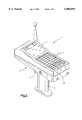
- FIG. 2is a perspective view of a typical electronic device in which a low voltage battery pack monitoring circuit of the present invention is disposed;
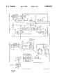
- FIG. 3is a schematic block diagram of the low voltage battery pack monitoring circuit of the present invention and selected other circuitry of the electronic device;
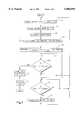
- FIG. 4is a flow chart illustrating a process of setting low voltage and power failure set points for the low voltage battery pack detection circuit
- FIG. 5is an exemplary empirically derived look up table for determination of V lowbatt and V failure set point voltage values by a microprocessor of the device.
- FIG. 6is a schematic block diagram of an alternate embodiment of the low voltage battery pack monitoring circuit of the present invention.
- FIG. 3One embodiment of low voltage battery pack monitoring circuitry of the present invention is shown schematically within a box labeled 12 in FIG. 3.
- the monitoring circuitry 12is disposed, along with other electronic circuitry and electronic systems in an interior region of a housing 6 of a portable data collection device 7 shown in FIG. 2. While the portable data collection device 6 includes a bar code dataform reading assembly actuated by a trigger 8, it should be appreciated that the monitoring circuitry 12 of the present invention is suitable for any portable electronic device and is not limited to use in the device 6 depicted in FIG. 2.
- the electronic circuitry and systems of the device 7is powered by a battery pack 14 disposed in a handle portion 9 of the housing 6.
- the battery pack 14includes a plurality of electrically coupled rechargeable battery cells 15 and also includes a digital memory 16 and a temperature sensing circuit 17.
- a suitable battery pack having a memory and a temperature sensing circuitis described in U.S. patent application Ser. No. 08/319,301, filed Oct. 6, 1994 and entitled "Battery System Including Data Storage Memory.” Application Ser. No. 08/319,301 is incorporated herein in its entirety by reference.
- the power output by the battery pack 14is coupled to power regulation circuitry 18.
- the power regulation circuitry 18provides appropriate regulated power to all electronic circuitry and systems of the electronic device 7 via a bus 20.
- a microprocessor 22controls operations of the device 7 and interfaces with an operator though the trigger 8, a keypad 10 and an interactive touch sensitive visual display screen 11.
- the microprocessor 22utilizes an empirical look up table to determine: a) an appropriate set point voltage, V lowbatt , at which a low battery pack power indication is triggered if the output voltage, V batt , across positive and negative terminals 23, 24 of the battery pack 14; and b) an appropriate power failure set point voltage, V failure , at which the device 7 enters a suspend mode.
- V lowbattthe device 7 is still operable but the operator is alerted that a replacement battery pack will be required shortly for continued operation of the device. If the device continues to be operated V batt will continue to decline.
- An analog to digital (A/D) converter 47is coupled between the temperature sensing circuitry 17 and the microprocessor 22 to digitize the analog temperature value output by the temperature sensing circuitry.
- the monitoring circuitry 12includes a first or low battery pack comparison circuit and a second or power failure comparison circuit.
- the first comparison circuitincludes a first or low battery register 26, a first digital to analog (D/A) converter 27 and a first or low battery comparator 28.
- the second comparison circuitincludes a second or power failure register 29, a second D/A converter 30 and a second or power failure comparator 31.
- a digital representation of the V lowbatt and V failure set point voltage valuesare stored in the low battery and power failure registers 26, 29 of the monitoring circuitry 12.
- the digital V lowbatt set point voltage value from the low battery register 26is input to the first D/A converter 27 which generates an analog V lowbatt value.
- the V lowbatt valueis input to a noninverting input of the first comparator 28.
- the digital V failure set point voltage value from the power failure register 29is input to the second D/A converter 30 which generates an analog V failure value.
- the V failure valueis input to an inverting input of the second comparator 31.
- An output 32 of the first comparator 28is electrically coupled to the microprocessor 22 while the output 33 of the second comparator 31 is electrically coupled reset inputs of first and second D flip-flops 34, 35.
- the Q output of the first D flip-flop 34is electrically coupled to a first switch 36 which, when closed, connects regulated power from the power regulation circuitry 18 to energize one or more selected high power consuming electronic systems 37 of the device 7.
- the first switch 36is electrically coupled to a backlight illumination system 38 of the visual display screen 11.
- the Q output of the second D flip-flop 35is electrically coupled to a second switch 39 which, when closed, energizes another high power consuming electronic system, in this case, a radio transceiver system 40.
- Typical examples of high power consuming electronic systems of the portable data collection device 7would include the backlight illumination system 38 for the visual display screen 11, an illumination module for the dataform reading assembly, communications circuitry including the radio transceiver 40, etc.
- the output 33 of the second comparator 39is also coupled to a third switch 41.
- the third switch 41couples a back up power supply in the form of a rechargeable battery 42 to the memory 25. By closing the third switch 47, the battery 42 will provide sufficient power to maintain the memory 40 for a limited time.
- the back up battery 42is charged by the power regulation circuitry 18 when the power pack 14 is sufficiently charged such that V batt >V lowbatt .
- the output 33 of the second comparator 31is also electrically coupled to the microprocessor 22.
- the first comparator 28compares V lowbatt to the unregulated voltage, V batt , across the battery pack 14. When V batt ⁇ V lowbatt , the output 32 of the first comparator 28 changes state and goes high.
- the microprocessor 22senses the change in state of the first comparator 28 and executes programming associated with a low battery condition which results in actuation of a light emitting diode 49 for a predetermined time and flashing of a low battery message on the display screen 11 for a predetermined time to notify the operator than a low battery pack voltage output condition has been reached.
- V battwill continue to decrease and at some point V batt ⁇ V failure . If the battery pack 14 is removed from the handle portion 9 of the housing 6 or if the battery pack 14 suffers catastrophic failure, V batt will abruptly fall below V failure . In any event, when V batt ⁇ V failure , the output 33 of the second comparator 31 changes state and goes low. The change in output state 33 of the second comparator 31 is opposite the change in output state 32 of the first comparator 28 because, in the case of the first comparator 28, V batt is coupled to the inverting input of the comparator while in the case of the second comparator 31, V batt is coupled to the noninverting input of the comparator.
- the selected electronic systems 34 coupled to the output 44 of the second comparator 39are turned off because the low output 33 of the second comparator 31 resets the D flip-flops 34, 35 causing the respective Q outputs to go low thereby turning off the first and second switches 36, 39 which cuts power from the power regulation circuitry 18 to the backlight illumination system 38 and the radio transceiver 40.
- D flip-flopsmay be added to the illustrative example shown in FIG. 3 to turn off other high power consuming electronic systems as desired.
- D inputs to the D flip-flops 34, 35are electrically coupled to the microprocessor 22.
- the microprocessor 22could change the Q output state of either or both of the D flip-flops 34, 35 to turn off either or both of the backlight illumination system 28 and the radio transceiver 40.
- the D flip-flops 34, 35 and the first and second switches 36, 39are hardware driven, that is, they do not depend on the microprocessor 22 executing code, the turning off of the selected electronic systems 37 is nearly instantaneous upon V batt ⁇ V failure and the microprocessor's execution of suspend mode code is not required to put the device 7 into a power saving or suspend mode.
- Also input to clock input CK of the D flip-flopsis an appropriate clocking signal generated by register write strobe logic 43.
- the output 33 of the second comparator 31is directly coupled to the third switch 41.
- the third switch 41When the second comparator output 33 goes low, the third switch 41 thereby coupling power from the back up battery 42 to the memory 25 (and any other volatile memory of the device 7).
- the output 33 of the second comparator 31is coupled to the microprocessor 22.
- the microprocessor 22senses the change in output state 33 of the second comparator 31 going from high to low and executes code to either turn off or reduces operations to a power saving minimum. Thus, changing state of the second comparator 31 causes the device 7 to enter the suspend mode of operation.
- FIG. 4is a flowchart of the battery pack monitoring process of the present invention.
- the microprocessor 22obtains battery cell parameters relating to the quality of the battery cells 15 from the memory 16 in the battery pack 14.
- the battery cell quality parametersinclude the number of life cycles (total number of charge/discharge cycles) and the quantity of charging cycles (total number of charge/discharge cycles since the most recent conditioning cycle) of each cell in the pack.
- the microprocessorrates the battery cell quality pack on a scale, for example, good, fair or poor quality.
- the microprocessor 22obtains a desired device warning time, that is, the expected device operating time between V lowbatt and V failure conditions when the device 7 is being used at an "average" power use or consumption rate.
- a desired time V lowbatt and V failure conditionsin terms of minutes via the keypad 10.
- the operatormay be given a predetermined selection of, for example, three desired times (5 minutes, 10 minutes, and 15 minutes) and may select one of the three by pressing one of three time selection keypad keys.
- the desired warning timemay be input by the operator via a keypad or keyboard or it may be calculated based on a predetermined value set by management and stored in the memory 40.
- Step 54the microprocessor 22 obtains a digital value representative of the current temperature of the battery cells in the battery pack 14 utilizing the temperature sensing circuitry 17.
- Step 56represents calculation of the power consumption rate. characteristics. That is, based on a past period of usage of the device 7, the microprocessor 22 can calculate an average power consumption rate. Alternately, two or more power consumption rates may be stored in memory 40 by the manufacturer. The power consumption rates would correspond to the manufacturer's estimate of power consumption based on different modes of using the device 7.
- using the device 7 in a dataform reading mode using the dataform reading assembly and using communications circuitry of the device to transmit decoded dataform data to a remote devicewould correspond to a high rate of power consumption
- using the device to enter data via the interactive display screen 11would correspond to a medium rate of power consumption
- using the device to enter data via the keypad 10 and not using the communications circuitrywould correspond to a low rate of power.
- the operatorBefore beginning a new work session or when a change in usage mode of the device 7 occurred, the operator would press a key on the keypad 10 to indicate the present mode of usage of the device 7.
- the microprocessor 22would then retrieve the corresponding power consumption rate from memory 40.
- Step 58represents the microprocessor's determination of the V lowbatt and V failure set point voltage values utilizing an empirically derived look up table stored in the memory 40.
- a simplified look up table 70is illustrated in FIG. 5. Values for V lowbatt and V failure in volts are found in columns 72, 74 respectively.
- the microprocessor 22finds the input variable combination of desired warning time (column 76), battery cell temperature (column 78), battery cell quality (column 80) and expected power consumption rate (column 82) in the table 70 and then reads the corresponding current V lowbatt and V failure set point voltage values.
- V lowbatt and V failureare dynamic values that will change as one or more of the input variables change during operation, e.g., mode of usage of the device 7 changes, battery cell temperature changes, battery cell quality decreases or the operator inputs a different desired warning time.
- the table 70represents a simplified table, with each of the input variable being limited to three discrete values for ease of presentation and understanding. One skilled in the art will appreciate that a more complex table would normally be employed with more than three values for each input variable being used.
- the monitoring circuitry 12continuously monitors whether a power failure condition has occurred, that is, whether V batt ⁇ V failure . If a power failure condition is determined by the second comparator 31, at step 62, the second comparator 31 changes output state 33 and causes the selected electronic systems 37 coupled to the D flip-flops 34, 35 and the first and second switches 36, 39 to be turned off as the device 7 enters the power saving suspend mode. Since the output 33 of the second comparator 31 is also coupled to the microprocessor 22, at step 63, the microprocessor will execute code relating to suspending operations of the device 7 by performing other functions in accord with instructions in the executed code to further reduce power consumption including, for example, reducing its own power consumption by operating at a reduced level. This step ends the process. Replacing or recharging the battery pack 14 (FIG. 3) and resuming from the suspend mode restarts the process.
- the monitoring circuitry 12Concurrently with continuously checking to determine if a power failure condition exists, the monitoring circuitry 12 also continuously monitors, at step 64, if a low battery pack output voltage condition has occurred, that is, whether V batt ⁇ V lowbatt . If a low pack battery output voltage condition has occurred, at step 66, the microprocessor 22 actuates the LED 49 as discussed above. If a low battery pack output voltage condition has not occurred, the process both loops back to step 64 to continue to monitor for a low battery pack output voltage condition and returns to step 50 where the V lowbatt and V failure set point voltage values by the microprocessor 22 if one or more of the input variables have changed.
- FIG. 6An alternate embodiment of the monitoring circuit of the present invention is shown in FIG. 6 at 120. This embodiment is especially suitable where the portable data collection device 7 includes a disk drive.
- components and circuitry shown in FIG. 6that are the same as the components and circuitry described with respect to the first embodiment of the monitoring circuit 12 have been assigned the same reference numerals.
- a first or low battery pack voltage comparison circuitis different than the comparison circuit in the first embodiment in that the first comparison circuit in the second embodiment does not include a comparator, a low battery register or a D/A converter. Instead, the first comparison circuit utilizes the microprocessor 22 to make the comparison of V batt and V lowbatt .
- the first comparison circuitcomprises an analog to digital (A/D) converter 44 and the microprocessor 22.
- the A/D converter 44has an input coupled to the positive battery pack terminal 23. Thus, the A/D converter receives as inputs an analog value of V batt and a ground signal (zero volts).
- the A/D converter 44determines the difference between the two inputs which is, of course, V batt , digitizes the V batt value and outputs the digitized value to the microprocessor 22.
- the microprocessor 22compares digital values of V batt and V lowbatt to determine if V batt ⁇ V lowbatt . If the microprocessor 22 determines a low battery pack output condition has occurred, it will execute code to actuate the LED 49 for a predetermined time and flash a low battery pack output voltage message of the display screen 11 for a predetermined time.
- a second or power failure comparison circuit of the monitoring circuit 120is identical to the second comparison circuit of the monitoring circuit 12 of the first embodiment. However, in this embodiment, it is assumed that the device 7 includes one or more bridge cells 45 which have sufficient power to run all the electronic systems of the device for a limited time to allow for an orderly shutdown of complex devices such as a disk drive by the microprocessor 22.
- the output 33 of the second or power failure comparator 31goes low when a power failure condition occurs, V batt ⁇ V failure .
- the second comparator output 33is coupled to a third switch 41 which is coupled to the power regulation circuitry 18 and positive terminals 23, 46 of the battery pack 14 and the bridge cells 45.
- the third switch 41electrically couples the battery pack 14 to the power regulation circuitry 18 and the bridge cells 45 are disconnected from the power regulation circuitry.
- the third switch 41electrically couples the bridge cells 45 to the power regulation circuitry 18 and disconnects the battery pack 14 from the power regulation circuitry.
- the bridge cells 45provide sufficient power to permit an orderly shut down of electronic systems such as a disk drive by the microprocessor 22.
- the backlight 38 and radio transceiver 40are turned off by the first and second D flip-flops 34, 35 and the first and second switches 36, 39 as described with respect to the first embodiment of the monitoring circuit.
Landscapes
- Engineering & Computer Science (AREA)
- Power Engineering (AREA)
- Physics & Mathematics (AREA)
- General Physics & Mathematics (AREA)
- Business, Economics & Management (AREA)
- Emergency Management (AREA)
- Tests Of Electric Status Of Batteries (AREA)
- Secondary Cells (AREA)
- Power Sources (AREA)
Abstract
Description
Claims (20)
Priority Applications (1)
| Application Number | Priority Date | Filing Date | Title |
|---|---|---|---|
| US08/699,093US5804894A (en) | 1996-08-16 | 1996-08-16 | Low voltage battery pack monitoring circuit with adjustable set points |
Applications Claiming Priority (1)
| Application Number | Priority Date | Filing Date | Title |
|---|---|---|---|
| US08/699,093US5804894A (en) | 1996-08-16 | 1996-08-16 | Low voltage battery pack monitoring circuit with adjustable set points |
Publications (1)
| Publication Number | Publication Date |
|---|---|
| US5804894Atrue US5804894A (en) | 1998-09-08 |
Family
ID=24807898
Family Applications (1)
| Application Number | Title | Priority Date | Filing Date |
|---|---|---|---|
| US08/699,093Expired - LifetimeUS5804894A (en) | 1996-08-16 | 1996-08-16 | Low voltage battery pack monitoring circuit with adjustable set points |
Country Status (1)
| Country | Link |
|---|---|
| US (1) | US5804894A (en) |
Cited By (97)
| Publication number | Priority date | Publication date | Assignee | Title |
|---|---|---|---|---|
| US6018232A (en)* | 1996-02-27 | 2000-01-25 | Fujitsu Limited | Method of operating battery powered computing device with radio transmitter |
| US6023151A (en)* | 1998-03-16 | 2000-02-08 | Eveready Battery Company, Inc. | Method and device for enhancing smart battery performance |
| WO2000048013A1 (en)* | 1999-02-11 | 2000-08-17 | Braun Gmbh | Method for determining a state of charge of a battery |
| US6134391A (en)* | 1998-06-22 | 2000-10-17 | Asahi Kogaku Kogyo Kabushiki Kaisha | Battery residual-power checking apparatus |
| US6188142B1 (en)* | 1996-09-14 | 2001-02-13 | Braun Gmbh | Method and arrangement for disconnecting consumers |
| US6191498B1 (en)* | 1999-07-19 | 2001-02-20 | Pacific Technology Co., Ltd. | Power-supplying device for generating different voltage outputs |
| US6242892B1 (en)* | 1997-09-03 | 2001-06-05 | Motorola, Inc. | Portable electronic device and method |
| US6265877B1 (en)* | 1997-09-30 | 2001-07-24 | Matsushita Electric Industrial Co., Ltd. | Method for determining an end of discharge voltage for a secondary battery |
| US20020140400A1 (en)* | 2001-03-14 | 2002-10-03 | International Business Machines Corporation | System, method and apparatus for controllable power supply |
| US20020194517A1 (en)* | 2001-05-09 | 2002-12-19 | Cohen Paul M. | Method and apparatus to modify power requirements for a system |
| US20030006290A1 (en)* | 2001-05-02 | 2003-01-09 | Hand Held Products, Inc. | Optical reader comprising soft key including permanent graphic indicia |
| US20030022043A1 (en)* | 2001-04-27 | 2003-01-30 | Plug Power Inc. | Fuel cell transient control scheme |
| US6513168B2 (en)* | 1998-01-16 | 2003-02-04 | Depuy Orthopaedics, Inc. | Head gear apparatus |
| US20030046503A1 (en)* | 2001-09-04 | 2003-03-06 | Park Jeong Min | Methods for saving data on the basis of the remaining capacity of a battery in a suspend mode and resuming operations using the saved data |
| US20030052873A1 (en)* | 2001-09-19 | 2003-03-20 | Nec Corporation | Method and circuit for driving display, and portable electronic device |
| US6697745B2 (en)* | 2000-12-27 | 2004-02-24 | Plug Power Inc. | Technique and apparatus to control the transient response of a fuel cell system |
| US20040164708A1 (en)* | 2003-02-21 | 2004-08-26 | Dusan Veselic | Circuit and method of operation for an electrical power supply |
| US20050044437A1 (en)* | 2003-08-19 | 2005-02-24 | Dunstan Robert A. | Power conservation in the absence of AC power |
| US6990691B2 (en) | 2003-07-18 | 2006-01-31 | Depuy Products, Inc. | Head gear apparatus |
| US20060036880A1 (en)* | 2004-08-15 | 2006-02-16 | Yasunori Maezawa | Automatic restart and resume of computing system upon reapplication of external power |
| US20060202857A1 (en)* | 2005-03-07 | 2006-09-14 | Hitachi Vehicle Energy, Ltd. | Status detector for power supply, power supply, and initial characteristic extracting device for use with power supply |
| US20070188150A1 (en)* | 2006-02-16 | 2007-08-16 | Fujitsu Ten Limited | System and method for supervising battery for vehicle |
| US20080144294A1 (en)* | 2006-12-06 | 2008-06-19 | Meir Adest | Removal component cartridge for increasing reliability in power harvesting systems |
| US20080150366A1 (en)* | 2006-12-06 | 2008-06-26 | Solaredge, Ltd. | Method for distributed power harvesting using dc power sources |
| US20080238368A1 (en)* | 2007-03-27 | 2008-10-02 | Honeywell International Inc. | Voltage regulator in a battery cell |
| US20090039852A1 (en)* | 2007-08-06 | 2009-02-12 | Solaredge Technologies Ltd. | Digital average input current control in power converter |
| US20090141522A1 (en)* | 2007-10-10 | 2009-06-04 | Solaredge, Ltd. | System and method for protection during inverter shutdown in distributed power installations |
| US20090146667A1 (en)* | 2007-12-05 | 2009-06-11 | Meir Adest | Testing of a photovoltaic panel |
| US20090147554A1 (en)* | 2007-12-05 | 2009-06-11 | Solaredge, Ltd. | Parallel connected inverters |
| US20090145480A1 (en)* | 2007-12-05 | 2009-06-11 | Meir Adest | Photovoltaic system power tracking method |
| WO2009087211A1 (en)* | 2008-01-11 | 2009-07-16 | Huf Hülsbeck & Fürst Gmbh & Co. Kg | Method for controlling a mobile identification transmitter |
| US20090206666A1 (en)* | 2007-12-04 | 2009-08-20 | Guy Sella | Distributed power harvesting systems using dc power sources |
| US7620834B1 (en)* | 2001-05-29 | 2009-11-17 | Palm, Inc. | Battery voltage sag avoidance algorithm for a wireless handheld device |
| US20100124027A1 (en)* | 2008-06-12 | 2010-05-20 | Lior Handelsman | Switching Circuit Layout With Heatsink |
| US20100297860A1 (en)* | 2009-05-22 | 2010-11-25 | Vadim Shmukler | Dual compressive connector |
| US20100294903A1 (en)* | 2009-05-25 | 2010-11-25 | Vadim Shmukler | Bracket for Connection of a Junction Box to Photovoltaic Panels |
| US20100295513A1 (en)* | 2008-01-17 | 2010-11-25 | Hewlett-Packard Development Compayn, L.P. | Backup power system management |
| US20100294528A1 (en)* | 2009-05-22 | 2010-11-25 | Guy Sella | Electrically isolated heat dissipating junction box |
| US20100301991A1 (en)* | 2009-05-26 | 2010-12-02 | Guy Sella | Theft detection and prevention in a power generation system |
| US7900361B2 (en) | 2006-12-06 | 2011-03-08 | Solaredge, Ltd. | Current bypass for distributed power harvesting systems using DC power sources |
| US20110084553A1 (en)* | 2007-12-04 | 2011-04-14 | Meir Adest | Distributed power system using direct current power sources |
| US20110125431A1 (en)* | 2007-12-05 | 2011-05-26 | Meir Adest | Testing of a Photovoltaic Panel |
| US20110121652A1 (en)* | 2006-12-06 | 2011-05-26 | Guy Sella | Pairing of components in a direct current distributed power generation system |
| US20110133552A1 (en)* | 2009-12-01 | 2011-06-09 | Yaron Binder | Dual Use Photovoltaic System |
| US20110181340A1 (en)* | 2010-01-27 | 2011-07-28 | Meir Gazit | Fast Voltage Level Shifter Circuit |
| US20110227551A1 (en)* | 2010-03-22 | 2011-09-22 | PINE VALLEY INVESTMENTS, INC., a Nevada corporation | Mobile wireless communications device including removable electrical power supply module and related methods |
| US8319471B2 (en) | 2006-12-06 | 2012-11-27 | Solaredge, Ltd. | Battery power delivery module |
| US8384243B2 (en) | 2007-12-04 | 2013-02-26 | Solaredge Technologies Ltd. | Distributed power harvesting systems using DC power sources |
| US8473250B2 (en) | 2006-12-06 | 2013-06-25 | Solaredge, Ltd. | Monitoring of distributed power harvesting systems using DC power sources |
| US8531055B2 (en) | 2006-12-06 | 2013-09-10 | Solaredge Ltd. | Safety mechanisms, wake up and shutdown methods in distributed power installations |
| US8570005B2 (en) | 2011-09-12 | 2013-10-29 | Solaredge Technologies Ltd. | Direct current link circuit |
| US8957645B2 (en) | 2008-03-24 | 2015-02-17 | Solaredge Technologies Ltd. | Zero voltage switching |
| US8988838B2 (en) | 2012-01-30 | 2015-03-24 | Solaredge Technologies Ltd. | Photovoltaic panel circuitry |
| US9000617B2 (en) | 2008-05-05 | 2015-04-07 | Solaredge Technologies, Ltd. | Direct current power combiner |
| US9088178B2 (en) | 2006-12-06 | 2015-07-21 | Solaredge Technologies Ltd | Distributed power harvesting systems using DC power sources |
| US9130401B2 (en) | 2006-12-06 | 2015-09-08 | Solaredge Technologies Ltd. | Distributed power harvesting systems using DC power sources |
| US9235228B2 (en) | 2012-03-05 | 2016-01-12 | Solaredge Technologies Ltd. | Direct current link circuit |
| US9300158B2 (en) | 2013-11-26 | 2016-03-29 | Motorola Solutions, Inc. | Method and apparatus for loading voltage thresholds from a battery for a device |
| US9318974B2 (en) | 2014-03-26 | 2016-04-19 | Solaredge Technologies Ltd. | Multi-level inverter with flying capacitor topology |
| US9401599B2 (en) | 2010-12-09 | 2016-07-26 | Solaredge Technologies Ltd. | Disconnection of a string carrying direct current power |
| US9548619B2 (en) | 2013-03-14 | 2017-01-17 | Solaredge Technologies Ltd. | Method and apparatus for storing and depleting energy |
| US9647442B2 (en) | 2010-11-09 | 2017-05-09 | Solaredge Technologies Ltd. | Arc detection and prevention in a power generation system |
| US9812984B2 (en) | 2012-01-30 | 2017-11-07 | Solaredge Technologies Ltd. | Maximizing power in a photovoltaic distributed power system |
| US9819178B2 (en) | 2013-03-15 | 2017-11-14 | Solaredge Technologies Ltd. | Bypass mechanism |
| US9831824B2 (en) | 2007-12-05 | 2017-11-28 | SolareEdge Technologies Ltd. | Current sensing on a MOSFET |
| US9853565B2 (en) | 2012-01-30 | 2017-12-26 | Solaredge Technologies Ltd. | Maximized power in a photovoltaic distributed power system |
| US9866098B2 (en) | 2011-01-12 | 2018-01-09 | Solaredge Technologies Ltd. | Serially connected inverters |
| US9870016B2 (en) | 2012-05-25 | 2018-01-16 | Solaredge Technologies Ltd. | Circuit for interconnected direct current power sources |
| US9941813B2 (en) | 2013-03-14 | 2018-04-10 | Solaredge Technologies Ltd. | High frequency multi-level inverter |
| US20180238969A1 (en)* | 2017-02-22 | 2018-08-23 | Bordrin Motor Corporation | Method for detecting power fade level of battery |
| US10061957B2 (en) | 2016-03-03 | 2018-08-28 | Solaredge Technologies Ltd. | Methods for mapping power generation installations |
| US10115841B2 (en) | 2012-06-04 | 2018-10-30 | Solaredge Technologies Ltd. | Integrated photovoltaic panel circuitry |
| US20190004117A1 (en)* | 2012-01-16 | 2019-01-03 | Maxim Integrated Products, Inc. | Integrated standard-compliant data acquisition device |
| US10230310B2 (en) | 2016-04-05 | 2019-03-12 | Solaredge Technologies Ltd | Safety switch for photovoltaic systems |
| CN110143180A (en)* | 2019-04-17 | 2019-08-20 | 苏州佳世达光电有限公司 | Electronic device and method for managing power supply |
| US10599113B2 (en) | 2016-03-03 | 2020-03-24 | Solaredge Technologies Ltd. | Apparatus and method for determining an order of power devices in power generation systems |
| US10673229B2 (en) | 2010-11-09 | 2020-06-02 | Solaredge Technologies Ltd. | Arc detection and prevention in a power generation system |
| US10673222B2 (en) | 2010-11-09 | 2020-06-02 | Solaredge Technologies Ltd. | Arc detection and prevention in a power generation system |
| KR20200070820A (en)* | 2018-12-10 | 2020-06-18 | 엘지디스플레이 주식회사 | Display Device |
| US10931119B2 (en) | 2012-01-11 | 2021-02-23 | Solaredge Technologies Ltd. | Photovoltaic module |
| US11018623B2 (en) | 2016-04-05 | 2021-05-25 | Solaredge Technologies Ltd. | Safety switch for photovoltaic systems |
| US11081608B2 (en) | 2016-03-03 | 2021-08-03 | Solaredge Technologies Ltd. | Apparatus and method for determining an order of power devices in power generation systems |
| US11175341B2 (en)* | 2016-11-25 | 2021-11-16 | Volvo Truck Corporation | Method and arrangment for classifying a voltage fault condition in an electrical storage system |
| US11177663B2 (en) | 2016-04-05 | 2021-11-16 | Solaredge Technologies Ltd. | Chain of power devices |
| DE102008012545B4 (en) | 2008-03-04 | 2022-01-20 | Robert Bosch Gmbh | Circuit and method for comparing voltages |
| US11264947B2 (en) | 2007-12-05 | 2022-03-01 | Solaredge Technologies Ltd. | Testing of a photovoltaic panel |
| US11296650B2 (en) | 2006-12-06 | 2022-04-05 | Solaredge Technologies Ltd. | System and method for protection during inverter shutdown in distributed power installations |
| US11309832B2 (en) | 2006-12-06 | 2022-04-19 | Solaredge Technologies Ltd. | Distributed power harvesting systems using DC power sources |
| US11569659B2 (en) | 2006-12-06 | 2023-01-31 | Solaredge Technologies Ltd. | Distributed power harvesting systems using DC power sources |
| US11687112B2 (en) | 2006-12-06 | 2023-06-27 | Solaredge Technologies Ltd. | Distributed power harvesting systems using DC power sources |
| US11728768B2 (en) | 2006-12-06 | 2023-08-15 | Solaredge Technologies Ltd. | Pairing of components in a direct current distributed power generation system |
| US11735910B2 (en) | 2006-12-06 | 2023-08-22 | Solaredge Technologies Ltd. | Distributed power system using direct current power sources |
| US11855231B2 (en) | 2006-12-06 | 2023-12-26 | Solaredge Technologies Ltd. | Distributed power harvesting systems using DC power sources |
| US11881814B2 (en) | 2005-12-05 | 2024-01-23 | Solaredge Technologies Ltd. | Testing of a photovoltaic panel |
| US11888387B2 (en) | 2006-12-06 | 2024-01-30 | Solaredge Technologies Ltd. | Safety mechanisms, wake up and shutdown methods in distributed power installations |
| US12057807B2 (en) | 2016-04-05 | 2024-08-06 | Solaredge Technologies Ltd. | Chain of power devices |
| US12418177B2 (en) | 2009-10-24 | 2025-09-16 | Solaredge Technologies Ltd. | Distributed power system using direct current power sources |
Citations (3)
| Publication number | Priority date | Publication date | Assignee | Title |
|---|---|---|---|---|
| US5541490A (en)* | 1992-11-13 | 1996-07-30 | Zenith Data Systems Corporation | Computer power supply system |
| US5633573A (en)* | 1994-11-10 | 1997-05-27 | Duracell, Inc. | Battery pack having a processor controlled battery operating system |
| US5666040A (en)* | 1996-08-27 | 1997-09-09 | Bourbeau; Frank | Networked battery monitor and control system and charging method |
- 1996
- 1996-08-16USUS08/699,093patent/US5804894A/ennot_activeExpired - Lifetime
Patent Citations (3)
| Publication number | Priority date | Publication date | Assignee | Title |
|---|---|---|---|---|
| US5541490A (en)* | 1992-11-13 | 1996-07-30 | Zenith Data Systems Corporation | Computer power supply system |
| US5633573A (en)* | 1994-11-10 | 1997-05-27 | Duracell, Inc. | Battery pack having a processor controlled battery operating system |
| US5666040A (en)* | 1996-08-27 | 1997-09-09 | Bourbeau; Frank | Networked battery monitor and control system and charging method |
Cited By (301)
| Publication number | Priority date | Publication date | Assignee | Title |
|---|---|---|---|---|
| US6018232A (en)* | 1996-02-27 | 2000-01-25 | Fujitsu Limited | Method of operating battery powered computing device with radio transmitter |
| US6188142B1 (en)* | 1996-09-14 | 2001-02-13 | Braun Gmbh | Method and arrangement for disconnecting consumers |
| US6242892B1 (en)* | 1997-09-03 | 2001-06-05 | Motorola, Inc. | Portable electronic device and method |
| US6265877B1 (en)* | 1997-09-30 | 2001-07-24 | Matsushita Electric Industrial Co., Ltd. | Method for determining an end of discharge voltage for a secondary battery |
| US6513168B2 (en)* | 1998-01-16 | 2003-02-04 | Depuy Orthopaedics, Inc. | Head gear apparatus |
| US6023151A (en)* | 1998-03-16 | 2000-02-08 | Eveready Battery Company, Inc. | Method and device for enhancing smart battery performance |
| US6134391A (en)* | 1998-06-22 | 2000-10-17 | Asahi Kogaku Kogyo Kabushiki Kaisha | Battery residual-power checking apparatus |
| US6236189B1 (en) | 1999-02-11 | 2001-05-22 | Braun Gmbh | Method for determining a charge status of a battery |
| WO2000048013A1 (en)* | 1999-02-11 | 2000-08-17 | Braun Gmbh | Method for determining a state of charge of a battery |
| US6191498B1 (en)* | 1999-07-19 | 2001-02-20 | Pacific Technology Co., Ltd. | Power-supplying device for generating different voltage outputs |
| US6697745B2 (en)* | 2000-12-27 | 2004-02-24 | Plug Power Inc. | Technique and apparatus to control the transient response of a fuel cell system |
| US20020140400A1 (en)* | 2001-03-14 | 2002-10-03 | International Business Machines Corporation | System, method and apparatus for controllable power supply |
| US6885115B2 (en)* | 2001-03-14 | 2005-04-26 | International Business Machines Corporation | System, method and apparatus for controllable power supply |
| US20030022043A1 (en)* | 2001-04-27 | 2003-01-30 | Plug Power Inc. | Fuel cell transient control scheme |
| US6977119B2 (en) | 2001-04-27 | 2005-12-20 | Plug Power Inc. | Fuel cell transient control scheme |
| US20030006290A1 (en)* | 2001-05-02 | 2003-01-09 | Hand Held Products, Inc. | Optical reader comprising soft key including permanent graphic indicia |
| US6899273B2 (en) | 2001-05-02 | 2005-05-31 | Hand Held Products, Inc. | Optical reader comprising soft key including permanent graphic indicia |
| US7155625B2 (en)* | 2001-05-09 | 2006-12-26 | Intel Corporation | Method and apparatus to modify power requirements for a system |
| US20020194517A1 (en)* | 2001-05-09 | 2002-12-19 | Cohen Paul M. | Method and apparatus to modify power requirements for a system |
| US20100050009A1 (en)* | 2001-05-29 | 2010-02-25 | Palm, Inc. | Battery voltage saf avoidance algorithm for a wireless handheld device |
| US7620834B1 (en)* | 2001-05-29 | 2009-11-17 | Palm, Inc. | Battery voltage sag avoidance algorithm for a wireless handheld device |
| US8392738B2 (en)* | 2001-05-29 | 2013-03-05 | Hewlett-Packard Development Company, L.P. | Battery voltage saf avoidance algorithm for a wireless handheld device |
| US20030046503A1 (en)* | 2001-09-04 | 2003-03-06 | Park Jeong Min | Methods for saving data on the basis of the remaining capacity of a battery in a suspend mode and resuming operations using the saved data |
| US7028220B2 (en)* | 2001-09-04 | 2006-04-11 | Lg Electronics Inc. | Methods for saving data on the basis of the remaining capacity of a battery in a suspend mode and resuming operations using the saved data |
| US20030052873A1 (en)* | 2001-09-19 | 2003-03-20 | Nec Corporation | Method and circuit for driving display, and portable electronic device |
| US7212193B2 (en)* | 2001-09-19 | 2007-05-01 | Nec Corporation | Method and circuit for driving display, and portable electronic device |
| US8541983B2 (en) | 2003-02-21 | 2013-09-24 | Blackberry Limited | Circuit and method of operation for an electrical power supply |
| US20100219797A1 (en)* | 2003-02-21 | 2010-09-02 | Research In Motion Limited | Circuit and Method of Operation for an Electrical Power Supply |
| US20040164708A1 (en)* | 2003-02-21 | 2004-08-26 | Dusan Veselic | Circuit and method of operation for an electrical power supply |
| US20100308777A1 (en)* | 2003-02-21 | 2010-12-09 | Research In Motion Limited | Circuit and method of operation for an electrical power supply |
| US7791319B2 (en)* | 2003-02-21 | 2010-09-07 | Research In Motion Limited | Circuit and method of operation for an electrical power supply |
| US7906940B2 (en)* | 2003-02-21 | 2011-03-15 | Research In Motion Limited | Circuit and method of operation for an electrical power supply |
| US7999514B2 (en) | 2003-02-21 | 2011-08-16 | Research In Motion Limited | Circuit and method of operation for an electrical power supply |
| US7847520B2 (en) | 2003-02-21 | 2010-12-07 | Research In Motion Limited | Circuit and method of operation for an electrical power supply |
| US6990691B2 (en) | 2003-07-18 | 2006-01-31 | Depuy Products, Inc. | Head gear apparatus |
| US7200873B2 (en) | 2003-07-18 | 2007-04-10 | Depuy Products, Inc. | Head gear apparatus having improved air flow arrangement |
| US7937779B2 (en) | 2003-07-18 | 2011-05-10 | Depuy Products | Head gear apparatus having improved air flow arrangement |
| US20050044437A1 (en)* | 2003-08-19 | 2005-02-24 | Dunstan Robert A. | Power conservation in the absence of AC power |
| US20060036880A1 (en)* | 2004-08-15 | 2006-02-16 | Yasunori Maezawa | Automatic restart and resume of computing system upon reapplication of external power |
| US7240227B2 (en)* | 2004-08-15 | 2007-07-03 | International Business Machines Corporation | Automatic restart and resume of computing system upon reapplication of external power |
| US8054045B2 (en) | 2005-03-07 | 2011-11-08 | Hitachi Vehicle Energy, Ltd. | Status detector for power supply, power supply, and initial characteristic extracting device for use with power supply |
| US7622894B2 (en)* | 2005-03-07 | 2009-11-24 | Hitachi Vehicle Energy, Ltd. | Status detector for power supply, power supply, and initial characteristic extracting device for use with power supply |
| US20100030499A1 (en)* | 2005-03-07 | 2010-02-04 | Hitachi Vehicle Energy, Ltd. | Status Detector for Power Supply, Power Supply, and Initial Characteristic Extracting Device for Use with Power Supply |
| US20060202857A1 (en)* | 2005-03-07 | 2006-09-14 | Hitachi Vehicle Energy, Ltd. | Status detector for power supply, power supply, and initial characteristic extracting device for use with power supply |
| US11881814B2 (en) | 2005-12-05 | 2024-01-23 | Solaredge Technologies Ltd. | Testing of a photovoltaic panel |
| US20070188150A1 (en)* | 2006-02-16 | 2007-08-16 | Fujitsu Ten Limited | System and method for supervising battery for vehicle |
| US8587151B2 (en) | 2006-12-06 | 2013-11-19 | Solaredge, Ltd. | Method for distributed power harvesting using DC power sources |
| US10447150B2 (en) | 2006-12-06 | 2019-10-15 | Solaredge Technologies Ltd. | Distributed power harvesting systems using DC power sources |
| US11594880B2 (en) | 2006-12-06 | 2023-02-28 | Solaredge Technologies Ltd. | Distributed power harvesting systems using DC power sources |
| US11183922B2 (en) | 2006-12-06 | 2021-11-23 | Solaredge Technologies Ltd. | Distributed power harvesting systems using DC power sources |
| US11855231B2 (en) | 2006-12-06 | 2023-12-26 | Solaredge Technologies Ltd. | Distributed power harvesting systems using DC power sources |
| US11735910B2 (en) | 2006-12-06 | 2023-08-22 | Solaredge Technologies Ltd. | Distributed power system using direct current power sources |
| US11728768B2 (en) | 2006-12-06 | 2023-08-15 | Solaredge Technologies Ltd. | Pairing of components in a direct current distributed power generation system |
| US20080144294A1 (en)* | 2006-12-06 | 2008-06-19 | Meir Adest | Removal component cartridge for increasing reliability in power harvesting systems |
| US10230245B2 (en) | 2006-12-06 | 2019-03-12 | Solaredge Technologies Ltd | Battery power delivery module |
| US11888387B2 (en) | 2006-12-06 | 2024-01-30 | Solaredge Technologies Ltd. | Safety mechanisms, wake up and shutdown methods in distributed power installations |
| US7900361B2 (en) | 2006-12-06 | 2011-03-08 | Solaredge, Ltd. | Current bypass for distributed power harvesting systems using DC power sources |
| US10097007B2 (en) | 2006-12-06 | 2018-10-09 | Solaredge Technologies Ltd. | Method for distributed power harvesting using DC power sources |
| US11961922B2 (en) | 2006-12-06 | 2024-04-16 | Solaredge Technologies Ltd. | Distributed power harvesting systems using DC power sources |
| US11962243B2 (en) | 2006-12-06 | 2024-04-16 | Solaredge Technologies Ltd. | Method for distributed power harvesting using DC power sources |
| US12027849B2 (en) | 2006-12-06 | 2024-07-02 | Solaredge Technologies Ltd. | Distributed power system using direct current power sources |
| US20110121652A1 (en)* | 2006-12-06 | 2011-05-26 | Guy Sella | Pairing of components in a direct current distributed power generation system |
| US9966766B2 (en) | 2006-12-06 | 2018-05-08 | Solaredge Technologies Ltd. | Battery power delivery module |
| US20110140536A1 (en)* | 2006-12-06 | 2011-06-16 | Meir Adest | Current bypass for distributed power harvesting systems using dc power sources |
| US11296650B2 (en) | 2006-12-06 | 2022-04-05 | Solaredge Technologies Ltd. | System and method for protection during inverter shutdown in distributed power installations |
| US9960667B2 (en) | 2006-12-06 | 2018-05-01 | Solaredge Technologies Ltd. | System and method for protection during inverter shutdown in distributed power installations |
| US8004117B2 (en) | 2006-12-06 | 2011-08-23 | Solaredge, Ltd. | Current bypass for distributed power harvesting systems using DC power sources |
| US8013472B2 (en) | 2006-12-06 | 2011-09-06 | Solaredge, Ltd. | Method for distributed power harvesting using DC power sources |
| US11309832B2 (en) | 2006-12-06 | 2022-04-19 | Solaredge Technologies Ltd. | Distributed power harvesting systems using DC power sources |
| US9960731B2 (en) | 2006-12-06 | 2018-05-01 | Solaredge Technologies Ltd. | Pairing of components in a direct current distributed power generation system |
| US9948233B2 (en) | 2006-12-06 | 2018-04-17 | Solaredge Technologies Ltd. | Distributed power harvesting systems using DC power sources |
| US12027970B2 (en) | 2006-12-06 | 2024-07-02 | Solaredge Technologies Ltd. | Safety mechanisms, wake up and shutdown methods in distributed power installations |
| US8319471B2 (en) | 2006-12-06 | 2012-11-27 | Solaredge, Ltd. | Battery power delivery module |
| US12032080B2 (en) | 2006-12-06 | 2024-07-09 | Solaredge Technologies Ltd. | Safety mechanisms, wake up and shutdown methods in distributed power installations |
| US12046940B2 (en) | 2006-12-06 | 2024-07-23 | Solaredge Technologies Ltd. | Battery power control |
| US10637393B2 (en) | 2006-12-06 | 2020-04-28 | Solaredge Technologies Ltd. | Distributed power harvesting systems using DC power sources |
| US12068599B2 (en) | 2006-12-06 | 2024-08-20 | Solaredge Technologies Ltd. | System and method for protection during inverter shutdown in distributed power installations |
| US8473250B2 (en) | 2006-12-06 | 2013-06-25 | Solaredge, Ltd. | Monitoring of distributed power harvesting systems using DC power sources |
| US11476799B2 (en) | 2006-12-06 | 2022-10-18 | Solaredge Technologies Ltd. | Distributed power harvesting systems using DC power sources |
| US8531055B2 (en) | 2006-12-06 | 2013-09-10 | Solaredge Ltd. | Safety mechanisms, wake up and shutdown methods in distributed power installations |
| US12276997B2 (en) | 2006-12-06 | 2025-04-15 | Solaredge Technologies Ltd. | Distributed power harvesting systems using DC power sources |
| US20080150366A1 (en)* | 2006-12-06 | 2008-06-26 | Solaredge, Ltd. | Method for distributed power harvesting using dc power sources |
| US9543889B2 (en) | 2006-12-06 | 2017-01-10 | Solaredge Technologies Ltd. | Distributed power harvesting systems using DC power sources |
| US11687112B2 (en) | 2006-12-06 | 2023-06-27 | Solaredge Technologies Ltd. | Distributed power harvesting systems using DC power sources |
| US9853490B2 (en) | 2006-12-06 | 2017-12-26 | Solaredge Technologies Ltd. | Distributed power system using direct current power sources |
| US12107417B2 (en) | 2006-12-06 | 2024-10-01 | Solaredge Technologies Ltd. | Distributed power harvesting systems using DC power sources |
| US10673253B2 (en) | 2006-12-06 | 2020-06-02 | Solaredge Technologies Ltd. | Battery power delivery module |
| US8659188B2 (en) | 2006-12-06 | 2014-02-25 | Solaredge Technologies Ltd. | Distributed power harvesting systems using DC power sources |
| US11073543B2 (en) | 2006-12-06 | 2021-07-27 | Solaredge Technologies Ltd. | Monitoring of distributed power harvesting systems using DC power sources |
| US11063440B2 (en) | 2006-12-06 | 2021-07-13 | Solaredge Technologies Ltd. | Method for distributed power harvesting using DC power sources |
| US11682918B2 (en) | 2006-12-06 | 2023-06-20 | Solaredge Technologies Ltd. | Battery power delivery module |
| US11569659B2 (en) | 2006-12-06 | 2023-01-31 | Solaredge Technologies Ltd. | Distributed power harvesting systems using DC power sources |
| US11043820B2 (en) | 2006-12-06 | 2021-06-22 | Solaredge Technologies Ltd. | Battery power delivery module |
| US11658482B2 (en) | 2006-12-06 | 2023-05-23 | Solaredge Technologies Ltd. | Distributed power harvesting systems using DC power sources |
| US11031861B2 (en) | 2006-12-06 | 2021-06-08 | Solaredge Technologies Ltd. | System and method for protection during inverter shutdown in distributed power installations |
| US11598652B2 (en) | 2006-12-06 | 2023-03-07 | Solaredge Technologies Ltd. | Monitoring of distributed power harvesting systems using DC power sources |
| US9680304B2 (en) | 2006-12-06 | 2017-06-13 | Solaredge Technologies Ltd. | Method for distributed power harvesting using DC power sources |
| US12388492B2 (en) | 2006-12-06 | 2025-08-12 | Solaredge Technologies Ltd. | Safety mechanisms, wake up and shutdown methods in distributed power installations |
| US9644993B2 (en) | 2006-12-06 | 2017-05-09 | Solaredge Technologies Ltd. | Monitoring of distributed power harvesting systems using DC power sources |
| US11569660B2 (en) | 2006-12-06 | 2023-01-31 | Solaredge Technologies Ltd. | Distributed power harvesting systems using DC power sources |
| US9041339B2 (en) | 2006-12-06 | 2015-05-26 | Solaredge Technologies Ltd. | Battery power delivery module |
| US9088178B2 (en) | 2006-12-06 | 2015-07-21 | Solaredge Technologies Ltd | Distributed power harvesting systems using DC power sources |
| US11002774B2 (en) | 2006-12-06 | 2021-05-11 | Solaredge Technologies Ltd. | Monitoring of distributed power harvesting systems using DC power sources |
| US9112379B2 (en) | 2006-12-06 | 2015-08-18 | Solaredge Technologies Ltd. | Pairing of components in a direct current distributed power generation system |
| US9130401B2 (en) | 2006-12-06 | 2015-09-08 | Solaredge Technologies Ltd. | Distributed power harvesting systems using DC power sources |
| US11575261B2 (en) | 2006-12-06 | 2023-02-07 | Solaredge Technologies Ltd. | Distributed power harvesting systems using DC power sources |
| US12316274B2 (en) | 2006-12-06 | 2025-05-27 | Solaredge Technologies Ltd. | Pairing of components in a direct current distributed power generation system |
| US11575260B2 (en) | 2006-12-06 | 2023-02-07 | Solaredge Technologies Ltd. | Distributed power harvesting systems using DC power sources |
| US12224706B2 (en) | 2006-12-06 | 2025-02-11 | Solaredge Technologies Ltd. | Pairing of components in a direct current distributed power generation system |
| US11579235B2 (en) | 2006-12-06 | 2023-02-14 | Solaredge Technologies Ltd. | Safety mechanisms, wake up and shutdown methods in distributed power installations |
| US9590526B2 (en) | 2006-12-06 | 2017-03-07 | Solaredge Technologies Ltd. | Safety mechanisms, wake up and shutdown methods in distributed power installations |
| US11594881B2 (en) | 2006-12-06 | 2023-02-28 | Solaredge Technologies Ltd. | Distributed power harvesting systems using DC power sources |
| US9368964B2 (en) | 2006-12-06 | 2016-06-14 | Solaredge Technologies Ltd. | Distributed power system using direct current power sources |
| US11594882B2 (en) | 2006-12-06 | 2023-02-28 | Solaredge Technologies Ltd. | Distributed power harvesting systems using DC power sources |
| US12281919B2 (en) | 2006-12-06 | 2025-04-22 | Solaredge Technologies Ltd. | Monitoring of distributed power harvesting systems using DC power sources |
| US20080238368A1 (en)* | 2007-03-27 | 2008-10-02 | Honeywell International Inc. | Voltage regulator in a battery cell |
| US7633261B2 (en) | 2007-03-27 | 2009-12-15 | Honeywell International Inc. | Primary battery with internal voltage regulator |
| US20090039852A1 (en)* | 2007-08-06 | 2009-02-12 | Solaredge Technologies Ltd. | Digital average input current control in power converter |
| US8319483B2 (en) | 2007-08-06 | 2012-11-27 | Solaredge Technologies Ltd. | Digital average input current control in power converter |
| US10516336B2 (en) | 2007-08-06 | 2019-12-24 | Solaredge Technologies Ltd. | Digital average input current control in power converter |
| US8773092B2 (en) | 2007-08-06 | 2014-07-08 | Solaredge Technologies Ltd. | Digital average input current control in power converter |
| US11594968B2 (en) | 2007-08-06 | 2023-02-28 | Solaredge Technologies Ltd. | Digital average input current control in power converter |
| US10116217B2 (en) | 2007-08-06 | 2018-10-30 | Solaredge Technologies Ltd. | Digital average input current control in power converter |
| US9673711B2 (en) | 2007-08-06 | 2017-06-06 | Solaredge Technologies Ltd. | Digital average input current control in power converter |
| US20090141522A1 (en)* | 2007-10-10 | 2009-06-04 | Solaredge, Ltd. | System and method for protection during inverter shutdown in distributed power installations |
| US8816535B2 (en) | 2007-10-10 | 2014-08-26 | Solaredge Technologies, Ltd. | System and method for protection during inverter shutdown in distributed power installations |
| US20110084553A1 (en)* | 2007-12-04 | 2011-04-14 | Meir Adest | Distributed power system using direct current power sources |
| US8963369B2 (en) | 2007-12-04 | 2015-02-24 | Solaredge Technologies Ltd. | Distributed power harvesting systems using DC power sources |
| US8618692B2 (en) | 2007-12-04 | 2013-12-31 | Solaredge Technologies Ltd. | Distributed power system using direct current power sources |
| US8384243B2 (en) | 2007-12-04 | 2013-02-26 | Solaredge Technologies Ltd. | Distributed power harvesting systems using DC power sources |
| US20090206666A1 (en)* | 2007-12-04 | 2009-08-20 | Guy Sella | Distributed power harvesting systems using dc power sources |
| US9853538B2 (en) | 2007-12-04 | 2017-12-26 | Solaredge Technologies Ltd. | Distributed power harvesting systems using DC power sources |
| US8324921B2 (en) | 2007-12-05 | 2012-12-04 | Solaredge Technologies Ltd. | Testing of a photovoltaic panel |
| US9291696B2 (en) | 2007-12-05 | 2016-03-22 | Solaredge Technologies Ltd. | Photovoltaic system power tracking method |
| US9407161B2 (en) | 2007-12-05 | 2016-08-02 | Solaredge Technologies Ltd. | Parallel connected inverters |
| US11264947B2 (en) | 2007-12-05 | 2022-03-01 | Solaredge Technologies Ltd. | Testing of a photovoltaic panel |
| US8599588B2 (en) | 2007-12-05 | 2013-12-03 | Solaredge Ltd. | Parallel connected inverters |
| US11183969B2 (en) | 2007-12-05 | 2021-11-23 | Solaredge Technologies Ltd. | Testing of a photovoltaic panel |
| US12055647B2 (en) | 2007-12-05 | 2024-08-06 | Solaredge Technologies Ltd. | Parallel connected inverters |
| US10644589B2 (en) | 2007-12-05 | 2020-05-05 | Solaredge Technologies Ltd. | Parallel connected inverters |
| US9831824B2 (en) | 2007-12-05 | 2017-11-28 | SolareEdge Technologies Ltd. | Current sensing on a MOSFET |
| US20090147554A1 (en)* | 2007-12-05 | 2009-06-11 | Solaredge, Ltd. | Parallel connected inverters |
| US11894806B2 (en) | 2007-12-05 | 2024-02-06 | Solaredge Technologies Ltd. | Testing of a photovoltaic panel |
| US10693415B2 (en) | 2007-12-05 | 2020-06-23 | Solaredge Technologies Ltd. | Testing of a photovoltaic panel |
| US20090145480A1 (en)* | 2007-12-05 | 2009-06-11 | Meir Adest | Photovoltaic system power tracking method |
| US8289742B2 (en) | 2007-12-05 | 2012-10-16 | Solaredge Ltd. | Parallel connected inverters |
| US11693080B2 (en) | 2007-12-05 | 2023-07-04 | Solaredge Technologies Ltd. | Parallel connected inverters |
| US20090146667A1 (en)* | 2007-12-05 | 2009-06-11 | Meir Adest | Testing of a photovoltaic panel |
| US11183923B2 (en) | 2007-12-05 | 2021-11-23 | Solaredge Technologies Ltd. | Parallel connected inverters |
| US9979280B2 (en) | 2007-12-05 | 2018-05-22 | Solaredge Technologies Ltd. | Parallel connected inverters |
| US20110125431A1 (en)* | 2007-12-05 | 2011-05-26 | Meir Adest | Testing of a Photovoltaic Panel |
| WO2009087211A1 (en)* | 2008-01-11 | 2009-07-16 | Huf Hülsbeck & Fürst Gmbh & Co. Kg | Method for controlling a mobile identification transmitter |
| US8648568B2 (en)* | 2008-01-17 | 2014-02-11 | Hewlett-Packard Development Company, L.P. | Backup power system management |
| US20100295513A1 (en)* | 2008-01-17 | 2010-11-25 | Hewlett-Packard Development Compayn, L.P. | Backup power system management |
| DE102008012545B4 (en) | 2008-03-04 | 2022-01-20 | Robert Bosch Gmbh | Circuit and method for comparing voltages |
| US9876430B2 (en) | 2008-03-24 | 2018-01-23 | Solaredge Technologies Ltd. | Zero voltage switching |
| US8957645B2 (en) | 2008-03-24 | 2015-02-17 | Solaredge Technologies Ltd. | Zero voltage switching |
| US9362743B2 (en) | 2008-05-05 | 2016-06-07 | Solaredge Technologies Ltd. | Direct current power combiner |
| US9000617B2 (en) | 2008-05-05 | 2015-04-07 | Solaredge Technologies, Ltd. | Direct current power combiner |
| US11424616B2 (en) | 2008-05-05 | 2022-08-23 | Solaredge Technologies Ltd. | Direct current power combiner |
| US12218498B2 (en) | 2008-05-05 | 2025-02-04 | Solaredge Technologies Ltd. | Direct current power combiner |
| US10468878B2 (en) | 2008-05-05 | 2019-11-05 | Solaredge Technologies Ltd. | Direct current power combiner |
| US20100124027A1 (en)* | 2008-06-12 | 2010-05-20 | Lior Handelsman | Switching Circuit Layout With Heatsink |
| US8630098B2 (en) | 2008-06-12 | 2014-01-14 | Solaredge Technologies Ltd. | Switching circuit layout with heatsink |
| US9537445B2 (en) | 2008-12-04 | 2017-01-03 | Solaredge Technologies Ltd. | Testing of a photovoltaic panel |
| US10461687B2 (en) | 2008-12-04 | 2019-10-29 | Solaredge Technologies Ltd. | Testing of a photovoltaic panel |
| US20100294528A1 (en)* | 2009-05-22 | 2010-11-25 | Guy Sella | Electrically isolated heat dissipating junction box |
| US9391385B2 (en) | 2009-05-22 | 2016-07-12 | Solaredge Technologies Ltd. | Dual compressive connector |
| US10411644B2 (en) | 2009-05-22 | 2019-09-10 | Solaredge Technologies, Ltd. | Electrically isolated heat dissipating junction box |
| US9006569B2 (en) | 2009-05-22 | 2015-04-14 | Solaredge Technologies Ltd. | Electrically isolated heat dissipating junction box |
| US20100297860A1 (en)* | 2009-05-22 | 2010-11-25 | Vadim Shmukler | Dual compressive connector |
| US8771024B2 (en) | 2009-05-22 | 2014-07-08 | Solaredge Technologies Ltd. | Dual compressive connector |
| US8303349B2 (en) | 2009-05-22 | 2012-11-06 | Solaredge Technologies Ltd. | Dual compressive connector |
| US10686402B2 (en) | 2009-05-22 | 2020-06-16 | Solaredge Technologies Ltd. | Electrically isolated heat dissipating junction box |
| US10879840B2 (en) | 2009-05-22 | 2020-12-29 | Solaredge Technologies Ltd. | Electrically isolated heat dissipating junction box |
| US8476524B2 (en) | 2009-05-22 | 2013-07-02 | Solaredge Technologies Ltd. | Electrically isolated heat dissipating junction box |
| US11509263B2 (en) | 2009-05-22 | 2022-11-22 | Solaredge Technologies Ltd. | Electrically isolated heat dissipating junction box |
| US11695371B2 (en) | 2009-05-22 | 2023-07-04 | Solaredge Technologies Ltd. | Electrically isolated heat dissipating junction box |
| US12074566B2 (en) | 2009-05-22 | 2024-08-27 | Solaredge Technologies Ltd. | Electrically isolated heat dissipating junction box |
| US9692164B2 (en) | 2009-05-22 | 2017-06-27 | Solaredge Technologies Ltd. | Dual compressive connector |
| US9748896B2 (en) | 2009-05-22 | 2017-08-29 | Solaredge Technologies Ltd. | Electrically isolated heat dissipating junction box |
| US9748897B2 (en) | 2009-05-22 | 2017-08-29 | Solaredge Technologies Ltd. | Electrically isolated heat dissipating junction box |
| US10090803B2 (en) | 2009-05-25 | 2018-10-02 | Solaredge Technologies Ltd. | Bracket for connection of a junction box to photovoltaic panels |
| US12199560B2 (en) | 2009-05-25 | 2025-01-14 | Solaredge Technologies Ltd. | Bracket for connection of a junction box to photovoltaic panels |
| US9813020B2 (en) | 2009-05-25 | 2017-11-07 | Solaredge Technologies Ltd. | Bracket for connection of a junction box to photovoltaic panels |
| US11088656B2 (en) | 2009-05-25 | 2021-08-10 | Solaredge Technologies Ltd. | Bracket for connection of a junction box to photovoltaic panels |
| US9438161B2 (en) | 2009-05-25 | 2016-09-06 | Solaredge Technologies Ltd. | Bracket for connection of a junction box to photovoltaic panels |
| US10622939B2 (en) | 2009-05-25 | 2020-04-14 | Solaredge Technologies Ltd. | Bracket for connection of a junction box to photovoltaic panels |
| US9099849B2 (en) | 2009-05-25 | 2015-08-04 | Solaredge Technologies Ltd. | Bracket for connection of a junction box to photovoltaic panels |
| US10432138B2 (en) | 2009-05-25 | 2019-10-01 | Solaredge Technologies Ltd. | Bracket for connection of a junction box to photovoltaic panels |
| US20100294903A1 (en)* | 2009-05-25 | 2010-11-25 | Vadim Shmukler | Bracket for Connection of a Junction Box to Photovoltaic Panels |
| US11817820B2 (en) | 2009-05-25 | 2023-11-14 | Solaredge Technologies Ltd. | Bracket for connection of a junction box to photovoltaic panels |
| US12306215B2 (en) | 2009-05-26 | 2025-05-20 | Solaredge Technologies Ltd. | Theft detection and prevention in a power generation system |
| US10969412B2 (en) | 2009-05-26 | 2021-04-06 | Solaredge Technologies Ltd. | Theft detection and prevention in a power generation system |
| US11867729B2 (en) | 2009-05-26 | 2024-01-09 | Solaredge Technologies Ltd. | Theft detection and prevention in a power generation system |
| US8947194B2 (en) | 2009-05-26 | 2015-02-03 | Solaredge Technologies Ltd. | Theft detection and prevention in a power generation system |
| US20100301991A1 (en)* | 2009-05-26 | 2010-12-02 | Guy Sella | Theft detection and prevention in a power generation system |
| US9869701B2 (en) | 2009-05-26 | 2018-01-16 | Solaredge Technologies Ltd. | Theft detection and prevention in a power generation system |
| US12418177B2 (en) | 2009-10-24 | 2025-09-16 | Solaredge Technologies Ltd. | Distributed power system using direct current power sources |
| US11056889B2 (en) | 2009-12-01 | 2021-07-06 | Solaredge Technologies Ltd. | Dual use photovoltaic system |
| US10270255B2 (en) | 2009-12-01 | 2019-04-23 | Solaredge Technologies Ltd | Dual use photovoltaic system |
| US11735951B2 (en) | 2009-12-01 | 2023-08-22 | Solaredge Technologies Ltd. | Dual use photovoltaic system |
| US8710699B2 (en) | 2009-12-01 | 2014-04-29 | Solaredge Technologies Ltd. | Dual use photovoltaic system |
| US12316158B2 (en) | 2009-12-01 | 2025-05-27 | Solaredge Technologies Ltd. | Dual use photovoltaic system |
| US9276410B2 (en) | 2009-12-01 | 2016-03-01 | Solaredge Technologies Ltd. | Dual use photovoltaic system |
| US20110133552A1 (en)* | 2009-12-01 | 2011-06-09 | Yaron Binder | Dual Use Photovoltaic System |
| US8766696B2 (en) | 2010-01-27 | 2014-07-01 | Solaredge Technologies Ltd. | Fast voltage level shifter circuit |
| US20110181340A1 (en)* | 2010-01-27 | 2011-07-28 | Meir Gazit | Fast Voltage Level Shifter Circuit |
| US9917587B2 (en) | 2010-01-27 | 2018-03-13 | Solaredge Technologies Ltd. | Fast voltage level shifter circuit |
| US9231570B2 (en) | 2010-01-27 | 2016-01-05 | Solaredge Technologies Ltd. | Fast voltage level shifter circuit |
| US9564882B2 (en) | 2010-01-27 | 2017-02-07 | Solaredge Technologies Ltd. | Fast voltage level shifter circuit |
| US20110227551A1 (en)* | 2010-03-22 | 2011-09-22 | PINE VALLEY INVESTMENTS, INC., a Nevada corporation | Mobile wireless communications device including removable electrical power supply module and related methods |
| US8791675B2 (en) | 2010-03-22 | 2014-07-29 | Pine Valley Investments, Inc. | Mobile wireless communications device including removable electrical power supply module and related methods |
| US11489330B2 (en) | 2010-11-09 | 2022-11-01 | Solaredge Technologies Ltd. | Arc detection and prevention in a power generation system |
| US10931228B2 (en) | 2010-11-09 | 2021-02-23 | Solaredge Technologies Ftd. | Arc detection and prevention in a power generation system |
| US10673229B2 (en) | 2010-11-09 | 2020-06-02 | Solaredge Technologies Ltd. | Arc detection and prevention in a power generation system |
| US12407158B2 (en) | 2010-11-09 | 2025-09-02 | Solaredge Technologies Ltd. | Arc detection and prevention in a power generation system |
| US12003215B2 (en) | 2010-11-09 | 2024-06-04 | Solaredge Technologies Ltd. | Arc detection and prevention in a power generation system |
| US11070051B2 (en) | 2010-11-09 | 2021-07-20 | Solaredge Technologies Ltd. | Arc detection and prevention in a power generation system |
| US11349432B2 (en) | 2010-11-09 | 2022-05-31 | Solaredge Technologies Ltd. | Arc detection and prevention in a power generation system |
| US10673222B2 (en) | 2010-11-09 | 2020-06-02 | Solaredge Technologies Ltd. | Arc detection and prevention in a power generation system |
| US9647442B2 (en) | 2010-11-09 | 2017-05-09 | Solaredge Technologies Ltd. | Arc detection and prevention in a power generation system |
| US9401599B2 (en) | 2010-12-09 | 2016-07-26 | Solaredge Technologies Ltd. | Disconnection of a string carrying direct current power |
| US12295184B2 (en) | 2010-12-09 | 2025-05-06 | Solaredge Technologies Ltd. | Disconnection of a string carrying direct current power |
| US11996488B2 (en) | 2010-12-09 | 2024-05-28 | Solaredge Technologies Ltd. | Disconnection of a string carrying direct current power |
| US11271394B2 (en) | 2010-12-09 | 2022-03-08 | Solaredge Technologies Ltd. | Disconnection of a string carrying direct current power |
| US9935458B2 (en) | 2010-12-09 | 2018-04-03 | Solaredge Technologies Ltd. | Disconnection of a string carrying direct current power |
| US12218505B2 (en) | 2011-01-12 | 2025-02-04 | Solaredge Technologies Ltd. | Serially connected inverters |
| US9866098B2 (en) | 2011-01-12 | 2018-01-09 | Solaredge Technologies Ltd. | Serially connected inverters |
| US11205946B2 (en) | 2011-01-12 | 2021-12-21 | Solaredge Technologies Ltd. | Serially connected inverters |
| US10666125B2 (en) | 2011-01-12 | 2020-05-26 | Solaredge Technologies Ltd. | Serially connected inverters |
| US10396662B2 (en) | 2011-09-12 | 2019-08-27 | Solaredge Technologies Ltd | Direct current link circuit |
| US8570005B2 (en) | 2011-09-12 | 2013-10-29 | Solaredge Technologies Ltd. | Direct current link circuit |
| US11979037B2 (en) | 2012-01-11 | 2024-05-07 | Solaredge Technologies Ltd. | Photovoltaic module |
| US10931119B2 (en) | 2012-01-11 | 2021-02-23 | Solaredge Technologies Ltd. | Photovoltaic module |
| US11130406B2 (en) | 2012-01-16 | 2021-09-28 | Maxim Integrated Products, Inc. | Integrated standard-compliant data acquisition device |
| US20190004117A1 (en)* | 2012-01-16 | 2019-01-03 | Maxim Integrated Products, Inc. | Integrated standard-compliant data acquisition device |
| US10539625B2 (en)* | 2012-01-16 | 2020-01-21 | Maxim Integrated Products, Inc. | Integrated standard-compliant data acquisition device |
| US12094306B2 (en) | 2012-01-30 | 2024-09-17 | Solaredge Technologies Ltd. | Photovoltaic panel circuitry |
| US10381977B2 (en) | 2012-01-30 | 2019-08-13 | Solaredge Technologies Ltd | Photovoltaic panel circuitry |
| US11183968B2 (en) | 2012-01-30 | 2021-11-23 | Solaredge Technologies Ltd. | Photovoltaic panel circuitry |
| US11620885B2 (en) | 2012-01-30 | 2023-04-04 | Solaredge Technologies Ltd. | Photovoltaic panel circuitry |
| US8988838B2 (en) | 2012-01-30 | 2015-03-24 | Solaredge Technologies Ltd. | Photovoltaic panel circuitry |
| US9853565B2 (en) | 2012-01-30 | 2017-12-26 | Solaredge Technologies Ltd. | Maximized power in a photovoltaic distributed power system |
| US11929620B2 (en) | 2012-01-30 | 2024-03-12 | Solaredge Technologies Ltd. | Maximizing power in a photovoltaic distributed power system |
| US9812984B2 (en) | 2012-01-30 | 2017-11-07 | Solaredge Technologies Ltd. | Maximizing power in a photovoltaic distributed power system |
| US10992238B2 (en) | 2012-01-30 | 2021-04-27 | Solaredge Technologies Ltd. | Maximizing power in a photovoltaic distributed power system |
| US10608553B2 (en) | 2012-01-30 | 2020-03-31 | Solaredge Technologies Ltd. | Maximizing power in a photovoltaic distributed power system |
| US12191668B2 (en) | 2012-01-30 | 2025-01-07 | Solaredge Technologies Ltd. | Maximizing power in a photovoltaic distributed power system |
| US9923516B2 (en) | 2012-01-30 | 2018-03-20 | Solaredge Technologies Ltd. | Photovoltaic panel circuitry |
| US10007288B2 (en) | 2012-03-05 | 2018-06-26 | Solaredge Technologies Ltd. | Direct current link circuit |
| US9639106B2 (en) | 2012-03-05 | 2017-05-02 | Solaredge Technologies Ltd. | Direct current link circuit |
| US9235228B2 (en) | 2012-03-05 | 2016-01-12 | Solaredge Technologies Ltd. | Direct current link circuit |
| US12306653B2 (en) | 2012-05-25 | 2025-05-20 | Solaredge Technologies Ltd. | Circuit for interconnected direct current power sources |
| US11740647B2 (en) | 2012-05-25 | 2023-08-29 | Solaredge Technologies Ltd. | Circuit for interconnected direct current power sources |
| US9870016B2 (en) | 2012-05-25 | 2018-01-16 | Solaredge Technologies Ltd. | Circuit for interconnected direct current power sources |
| US11334104B2 (en) | 2012-05-25 | 2022-05-17 | Solaredge Technologies Ltd. | Circuit for interconnected direct current power sources |
| US10705551B2 (en) | 2012-05-25 | 2020-07-07 | Solaredge Technologies Ltd. | Circuit for interconnected direct current power sources |
| US12218628B2 (en) | 2012-06-04 | 2025-02-04 | Solaredge Technologies Ltd. | Integrated photovoltaic panel circuitry |
| US11177768B2 (en) | 2012-06-04 | 2021-11-16 | Solaredge Technologies Ltd. | Integrated photovoltaic panel circuitry |
| US10115841B2 (en) | 2012-06-04 | 2018-10-30 | Solaredge Technologies Ltd. | Integrated photovoltaic panel circuitry |
| US12003107B2 (en) | 2013-03-14 | 2024-06-04 | Solaredge Technologies Ltd. | Method and apparatus for storing and depleting energy |
| US9941813B2 (en) | 2013-03-14 | 2018-04-10 | Solaredge Technologies Ltd. | High frequency multi-level inverter |
| US10778025B2 (en) | 2013-03-14 | 2020-09-15 | Solaredge Technologies Ltd. | Method and apparatus for storing and depleting energy |
| US9548619B2 (en) | 2013-03-14 | 2017-01-17 | Solaredge Technologies Ltd. | Method and apparatus for storing and depleting energy |
| US12255457B2 (en) | 2013-03-14 | 2025-03-18 | Solaredge Technologies Ltd. | Method and apparatus for storing and depleting energy |
| US11545912B2 (en) | 2013-03-14 | 2023-01-03 | Solaredge Technologies Ltd. | High frequency multi-level inverter |
| US11742777B2 (en) | 2013-03-14 | 2023-08-29 | Solaredge Technologies Ltd. | High frequency multi-level inverter |
| US12119758B2 (en) | 2013-03-14 | 2024-10-15 | Solaredge Technologies Ltd. | High frequency multi-level inverter |
| US12132125B2 (en) | 2013-03-15 | 2024-10-29 | Solaredge Technologies Ltd. | Bypass mechanism |
| US11424617B2 (en) | 2013-03-15 | 2022-08-23 | Solaredge Technologies Ltd. | Bypass mechanism |
| US9819178B2 (en) | 2013-03-15 | 2017-11-14 | Solaredge Technologies Ltd. | Bypass mechanism |
| US10651647B2 (en) | 2013-03-15 | 2020-05-12 | Solaredge Technologies Ltd. | Bypass mechanism |
| US9300158B2 (en) | 2013-11-26 | 2016-03-29 | Motorola Solutions, Inc. | Method and apparatus for loading voltage thresholds from a battery for a device |
| US12136890B2 (en) | 2014-03-26 | 2024-11-05 | Solaredge Technologies Ltd. | Multi-level inverter |
| US11632058B2 (en) | 2014-03-26 | 2023-04-18 | Solaredge Technologies Ltd. | Multi-level inverter |
| US11855552B2 (en) | 2014-03-26 | 2023-12-26 | Solaredge Technologies Ltd. | Multi-level inverter |
| US10886831B2 (en) | 2014-03-26 | 2021-01-05 | Solaredge Technologies Ltd. | Multi-level inverter |
| US9318974B2 (en) | 2014-03-26 | 2016-04-19 | Solaredge Technologies Ltd. | Multi-level inverter with flying capacitor topology |
| US11296590B2 (en) | 2014-03-26 | 2022-04-05 | Solaredge Technologies Ltd. | Multi-level inverter |
| US10886832B2 (en) | 2014-03-26 | 2021-01-05 | Solaredge Technologies Ltd. | Multi-level inverter |
| US10540530B2 (en) | 2016-03-03 | 2020-01-21 | Solaredge Technologies Ltd. | Methods for mapping power generation installations |
| US12224365B2 (en) | 2016-03-03 | 2025-02-11 | Solaredge Technologies Ltd. | Apparatus and method for determining an order of power devices in power generation systems |
| US11538951B2 (en) | 2016-03-03 | 2022-12-27 | Solaredge Technologies Ltd. | Apparatus and method for determining an order of power devices in power generation systems |
| US11824131B2 (en) | 2016-03-03 | 2023-11-21 | Solaredge Technologies Ltd. | Apparatus and method for determining an order of power devices in power generation systems |
| US10599113B2 (en) | 2016-03-03 | 2020-03-24 | Solaredge Technologies Ltd. | Apparatus and method for determining an order of power devices in power generation systems |
| US11081608B2 (en) | 2016-03-03 | 2021-08-03 | Solaredge Technologies Ltd. | Apparatus and method for determining an order of power devices in power generation systems |
| US10061957B2 (en) | 2016-03-03 | 2018-08-28 | Solaredge Technologies Ltd. | Methods for mapping power generation installations |
| US10230310B2 (en) | 2016-04-05 | 2019-03-12 | Solaredge Technologies Ltd | Safety switch for photovoltaic systems |
| US11201476B2 (en) | 2016-04-05 | 2021-12-14 | Solaredge Technologies Ltd. | Photovoltaic power device and wiring |
| US11018623B2 (en) | 2016-04-05 | 2021-05-25 | Solaredge Technologies Ltd. | Safety switch for photovoltaic systems |
| US11177663B2 (en) | 2016-04-05 | 2021-11-16 | Solaredge Technologies Ltd. | Chain of power devices |
| US11870250B2 (en) | 2016-04-05 | 2024-01-09 | Solaredge Technologies Ltd. | Chain of power devices |
| US12057807B2 (en) | 2016-04-05 | 2024-08-06 | Solaredge Technologies Ltd. | Chain of power devices |
| US12348182B2 (en) | 2016-04-05 | 2025-07-01 | Solaredge Technologies Ltd. | Safety switch for photovoltaic systems |
| US11175341B2 (en)* | 2016-11-25 | 2021-11-16 | Volvo Truck Corporation | Method and arrangment for classifying a voltage fault condition in an electrical storage system |
| US20180238969A1 (en)* | 2017-02-22 | 2018-08-23 | Bordrin Motor Corporation | Method for detecting power fade level of battery |
| KR20200070820A (en)* | 2018-12-10 | 2020-06-18 | 엘지디스플레이 주식회사 | Display Device |
| US11062651B2 (en)* | 2018-12-10 | 2021-07-13 | Lg Display Co., Ltd. | Display device |
| CN110143180A (en)* | 2019-04-17 | 2019-08-20 | 苏州佳世达光电有限公司 | Electronic device and method for managing power supply |
| US11569680B2 (en)* | 2019-04-17 | 2023-01-31 | Qisda Corporation | Electronic device and power management method |
Similar Documents
| Publication | Publication Date | Title |
|---|---|---|
| US5804894A (en) | Low voltage battery pack monitoring circuit with adjustable set points | |
| US5349668A (en) | Battery operated computer having improved battery monitor and cell reversal protection circuit | |
| JP2708344B2 (en) | Computer system | |
| US5187425A (en) | Rechargeable battery controller | |
| US5345392A (en) | Battery charge monitor for a personal computer | |
| US4743831A (en) | Apparatus and method for indicating remaining battery life in a battery powered device | |
| US5739596A (en) | Power supply for an electronic device and power delivery method therefor | |
| US5432429A (en) | System for charging/monitoring batteries for a microprocessor based system | |
| US5600230A (en) | Smart battery providing programmable remaining capacity and run-time alarms based on battery-specific characteristics | |
| US6714016B2 (en) | Method for displaying information concerning power consumption and electronic device | |
| US5572110A (en) | Smart battery charger system | |
| US6236226B1 (en) | Test method and system for uninterruptible power supply | |
| JP4474095B2 (en) | Adaptable residual quantity measurement for battery-powered electronics | |
| KR910005595B1 (en) | Computer systems power supply apparatus with micro computer | |
| US5424800A (en) | Camera having solar battery and secondary battery | |
| KR102167429B1 (en) | Appratus and method for prevention over-discharge and restarting energy storeage system | |
| JPH10164764A (en) | Battery capacity monitoring method | |
| JPH09308131A (en) | Electronic device and control method thereof | |
| EP0560510A1 (en) | Battery operated computer and method for managing battery power in battery operated computer | |
| JPH10178747A (en) | Charger | |
| JP2780699B2 (en) | Battery control method and power supply control circuit for personal computer | |
| EP0653826A2 (en) | Battery-driven electronic appliance | |
| US20070052393A1 (en) | Apparatus for preventing a malfunction | |
| JP2809661B2 (en) | Battery driven information processing device, battery power supply system, and battery management device | |
| JPH09237137A (en) | Computer system and control method of power supply control device applied to computer system |
Legal Events
| Date | Code | Title | Description |
|---|---|---|---|
| AS | Assignment | Owner name:TELXON CORPORATION, OHIO Free format text:ASSIGNMENT OF ASSIGNORS INTEREST;ASSIGNORS:LEESON, RANDAL A.;SHOOBRIDGE, RICHARD;REEL/FRAME:008174/0893 Effective date:19960816 | |
| STCF | Information on status: patent grant | Free format text:PATENTED CASE | |
| AS | Assignment | Owner name:BANK OF NEW YORK, THE, NEW YORK Free format text:SECURITY INTEREST;ASSIGNOR:TELXON CORPORATION;REEL/FRAME:009817/0901 Effective date:19990326 | |
| AS | Assignment | Owner name:BANK ONE, NA, OHIO Free format text:ASSIGNMENT OF ASSIGNORS INTEREST;ASSIGNOR:TELXON CORPORATION, A DELAWARE CORPORATION;REEL/FRAME:009866/0723 Effective date:19990326 | |
| AS | Assignment | Owner name:TELXON CORPORATION, OHIO Free format text:RELEASE BY SECURED PARTY;ASSIGNOR:THE BANK OF NEW YORK, AS AGENT;REEL/FRAME:010216/0776 Effective date:19990830 Owner name:FOOTHILL CAPITAL CORPORATION AS AGENT, CALIFORNIA Free format text:SECURITY INTEREST;ASSIGNOR:TELXON CORPORATION;REEL/FRAME:010216/0081 Effective date:19990826 Owner name:TELXON CORPORATION, OHIO Free format text:RELEASE OF SECURITY INTEREST;ASSIGNOR:BANK ONE, NA;REEL/FRAME:010216/0050 Effective date:19990830 | |
| FPAY | Fee payment | Year of fee payment:4 | |
| AS | Assignment | Owner name:SYMBOL TECHNOLOGIES, INC., NEW YORK Free format text:ASSIGNMENT OF ASSIGNORS INTEREST;ASSIGNOR:TELXON CORPORATION;REEL/FRAME:012795/0070 Effective date:20020327 | |
| AS | Assignment | Owner name:JPMORGAN CHASE BANK, N.A., NEW YORK Free format text:SECURITY INTEREST;ASSIGNOR:SYMBOL TECHNOLOGIES, INC.;REEL/FRAME:016116/0203 Effective date:20041229 | |
| AS | Assignment | Owner name:TELXON CORPORATION, OHIO Free format text:RELEASE OF SECURITY AGREEMENT;ASSIGNOR:WELLS FARGO FOOTHILL, INC. (FORMERLY FOOTHILL CAPITAL CORPORATION);REEL/FRAME:016621/0303 Effective date:20050716 | |
| FPAY | Fee payment | Year of fee payment:8 | |
| FPAY | Fee payment | Year of fee payment:12 | |
| AS | Assignment | Owner name:SYMBOL TECHNOLOGIES, INC., NEW YORK Free format text:RELEASE BY SECURED PARTY;ASSIGNOR:JPMORGANCHASE BANK, N.A.;REEL/FRAME:025441/0228 Effective date:20060901 | |
| AS | Assignment | Owner name:MORGAN STANLEY SENIOR FUNDING, INC. AS THE COLLATERAL AGENT, MARYLAND Free format text:SECURITY AGREEMENT;ASSIGNORS:ZIH CORP.;LASER BAND, LLC;ZEBRA ENTERPRISE SOLUTIONS CORP.;AND OTHERS;REEL/FRAME:034114/0270 Effective date:20141027 Owner name:MORGAN STANLEY SENIOR FUNDING, INC. AS THE COLLATE Free format text:SECURITY AGREEMENT;ASSIGNORS:ZIH CORP.;LASER BAND, LLC;ZEBRA ENTERPRISE SOLUTIONS CORP.;AND OTHERS;REEL/FRAME:034114/0270 Effective date:20141027 | |
| AS | Assignment | Owner name:SYMBOL TECHNOLOGIES, LLC, NEW YORK Free format text:CHANGE OF NAME;ASSIGNOR:SYMBOL TECHNOLOGIES, INC.;REEL/FRAME:036083/0640 Effective date:20150410 | |
| AS | Assignment | Owner name:SYMBOL TECHNOLOGIES, INC., NEW YORK Free format text:RELEASE BY SECURED PARTY;ASSIGNOR:MORGAN STANLEY SENIOR FUNDING, INC.;REEL/FRAME:036371/0738 Effective date:20150721 |