US5804436A - Apparatus and method for real-time measurement of cellular response - Google Patents
Apparatus and method for real-time measurement of cellular responseDownload PDFInfo
- Publication number
- US5804436A US5804436AUS08/691,356US69135696AUS5804436AUS 5804436 AUS5804436 AUS 5804436AUS 69135696 AUS69135696 AUS 69135696AUS 5804436 AUS5804436 AUS 5804436A
- Authority
- US
- United States
- Prior art keywords
- coupled
- compound
- test compound
- mixing chamber
- standard
- Prior art date
- Legal status (The legal status is an assumption and is not a legal conclusion. Google has not performed a legal analysis and makes no representation as to the accuracy of the status listed.)
- Expired - Lifetime
Links
Images


Classifications
- G—PHYSICS
- G01—MEASURING; TESTING
- G01N—INVESTIGATING OR ANALYSING MATERIALS BY DETERMINING THEIR CHEMICAL OR PHYSICAL PROPERTIES
- G01N33/00—Investigating or analysing materials by specific methods not covered by groups G01N1/00 - G01N31/00
- G01N33/48—Biological material, e.g. blood, urine; Haemocytometers
- G01N33/50—Chemical analysis of biological material, e.g. blood, urine; Testing involving biospecific ligand binding methods; Immunological testing
- G01N33/5005—Chemical analysis of biological material, e.g. blood, urine; Testing involving biospecific ligand binding methods; Immunological testing involving human or animal cells
- G01N33/5008—Chemical analysis of biological material, e.g. blood, urine; Testing involving biospecific ligand binding methods; Immunological testing involving human or animal cells for testing or evaluating the effect of chemical or biological compounds, e.g. drugs, cosmetics
- G01N33/502—Chemical analysis of biological material, e.g. blood, urine; Testing involving biospecific ligand binding methods; Immunological testing involving human or animal cells for testing or evaluating the effect of chemical or biological compounds, e.g. drugs, cosmetics for testing non-proliferative effects
- G—PHYSICS
- G01—MEASURING; TESTING
- G01N—INVESTIGATING OR ANALYSING MATERIALS BY DETERMINING THEIR CHEMICAL OR PHYSICAL PROPERTIES
- G01N33/00—Investigating or analysing materials by specific methods not covered by groups G01N1/00 - G01N31/00
- G01N33/48—Biological material, e.g. blood, urine; Haemocytometers
- G01N33/50—Chemical analysis of biological material, e.g. blood, urine; Testing involving biospecific ligand binding methods; Immunological testing
- G01N33/5005—Chemical analysis of biological material, e.g. blood, urine; Testing involving biospecific ligand binding methods; Immunological testing involving human or animal cells
- G01N33/5008—Chemical analysis of biological material, e.g. blood, urine; Testing involving biospecific ligand binding methods; Immunological testing involving human or animal cells for testing or evaluating the effect of chemical or biological compounds, e.g. drugs, cosmetics
- G—PHYSICS
- G01—MEASURING; TESTING
- G01N—INVESTIGATING OR ANALYSING MATERIALS BY DETERMINING THEIR CHEMICAL OR PHYSICAL PROPERTIES
- G01N33/00—Investigating or analysing materials by specific methods not covered by groups G01N1/00 - G01N31/00
- G01N33/48—Biological material, e.g. blood, urine; Haemocytometers
- G01N33/50—Chemical analysis of biological material, e.g. blood, urine; Testing involving biospecific ligand binding methods; Immunological testing
- G01N33/68—Chemical analysis of biological material, e.g. blood, urine; Testing involving biospecific ligand binding methods; Immunological testing involving proteins, peptides or amino acids
- G01N33/6872—Intracellular protein regulatory factors and their receptors, e.g. including ion channels
- G—PHYSICS
- G01—MEASURING; TESTING
- G01N—INVESTIGATING OR ANALYSING MATERIALS BY DETERMINING THEIR CHEMICAL OR PHYSICAL PROPERTIES
- G01N35/00—Automatic analysis not limited to methods or materials provided for in any single one of groups G01N1/00 - G01N33/00; Handling materials therefor
- G—PHYSICS
- G01—MEASURING; TESTING
- G01N—INVESTIGATING OR ANALYSING MATERIALS BY DETERMINING THEIR CHEMICAL OR PHYSICAL PROPERTIES
- G01N35/00—Automatic analysis not limited to methods or materials provided for in any single one of groups G01N1/00 - G01N33/00; Handling materials therefor
- G01N35/10—Devices for transferring samples or any liquids to, in, or from, the analysis apparatus, e.g. suction devices, injection devices
- G01N35/1095—Devices for transferring samples or any liquids to, in, or from, the analysis apparatus, e.g. suction devices, injection devices for supplying the samples to flow-through analysers
- G—PHYSICS
- G01—MEASURING; TESTING
- G01N—INVESTIGATING OR ANALYSING MATERIALS BY DETERMINING THEIR CHEMICAL OR PHYSICAL PROPERTIES
- G01N2510/00—Detection of programmed cell death, i.e. apoptosis
Definitions
- This inventionrelates generally to an apparatus for screening and the pharmacological profiling of compounds modulating a cellular physiological response.
- This inventionalso relates to devices for rapid assessment of the properties of compounds that modulate the activities of cell surface receptors and ion channels. More specifically, this invention relates to methods and apparatus for detecting, evaluating and characterizing the ability and potency of substances to act as agonists or antagonists against receptors and ion channels localized on a cell surface membrane.
- Biological cellscontain receptor molecules located on their external membrane. The function of these receptors is to "sense" the cell environment and supply the cell with an input signal about any changes in the environment.
- such cell environmentis comprised of the neighboring cells and the function of the receptor is to allow cells to communicate with each other directly (the paracrine regulatory system) or indirectly (the endocrine regulatory system) thus achieving harmonized response of a tissue, organ or a whole organism.
- the surface localized receptorsprovide a means for detecting extracellular environment.
- the surface localized receptorstransmit this information about extracellular environment into the cell through specific intracellular pathways in such a way that the cell responds in the specific fashion to accommodate these changes.
- the cell responsewould be abnormal causing malfunctioning of a tissue or an organ.
- adrenergic receptorsinteract with adrenaline and noradrenaline
- cholinergic receptorsinteract with acetylcholine
- serotoninergic receptorsinteract with 5-hydroxytriptamine, dopamineergic with DOPA and so on.
- the cells derived from the different tissuesinvariably express specific sets of tissue receptors. Different types of receptors are connected to different signal transduction pathways. For example, nicotinic cholinergic receptor, upon binding acetylcholine molecule, directly activates sodium channel (Claudio et al., 1987, is incorporated herein by reference).
- G-protein coupled receptorsactivate enzymes of second messenger pathways, for example, adenylate cyclase or phospholipase C with subsequent activation of cAMP or phosphoinositide cascades (Divecha and Itvine, 1995, is incorporated herein by reference).
- Receptor tyrosine kinasesactivate cascade of MEK/MAPK kinases leading to cell differentiation and proliferation (Marshall, 1995 and Herskowitz, 1995, are incorporated herein by reference)!.
- Cytokine receptorsactivate JAK/STAT cascade which in turn can regulate other pathways as well as activate gene transcription (Hill & Treisman, 1995, is incorporated herein by reference).
- the cell surface membranecarries ion pumps, ion transporters and ion channels. These molecular assemblies work in concert to maintain intracellular ion homeostasis. Any changes in the activity of these systems would cause a shift in the intracellular concentrations of ions and consequently to the cell metabolic response.
- Ion pumpsact to maintain transmembrane ion gradients utilizing ATP as a source of energy.
- the examples of the ion pumpsare: Na + /K + -ATPase maintaining transmembrane gradient of sodium and potassium ions, Ca 2+ - ATPase maintaining transmembrane gradient of calcium ions and H + -ATPase maintaining transmembrane gradient of protons.
- Ion transportersuse the electrochemical energy of transmembrane gradients of one ion species to maintain gradients of other ion counterpart.
- the Na + /Ca 2+ -exchangeruses the chemical potential of the sodium gradient directed inward to pump out calcium ions against their chemical potential.
- Ion channelsupon activation, allow for the ions to move across the cell membrane in accordance with their electrochemical potential.
- Ligand-gated channelsare activated to the open state upon binding a certain ligand with the chemoreceptor part of their molecules.
- the classical example of ligand-gated channelsis nicotinic cholinergic receptor which, at the same time, is the sodium channel.
- the type of biological activity of the compounds, agonist or antagonistmay be determined in the cell based assays.
- cells cotransfected with a receptor gene and reporter gene constructare used to provide means for identification of agonist and antagonist potential pharmaceutical compounds.
- These methodsare inconvenient because they require very laborious manipulations with gene transfection procedures, are highly time consuming and use artificially modified cells.
- several control experiments with a positive and negative control cell linesshould be performed as well.
- Ionized calciumunlike other intracellular ion events, e.g. changes in the intracellular concentrations of protons, sodium, magnesium, or potassium, serves as the most common element in different signal transduction pathways of the cells ranging from bacteria to specialized neurons (Clapham, 1995, is incorporated herein by reference). There are two major pools which supply signal transduction pathways in the cell with the calcium ions, extracellular space and the endoplasmic reticulum. There are several mechanisms to introduce small bursts of calcium into cytosol for signal transduction.
- GPCSRG-protein coupled serpentine receptors
- RTKreceptor tyrosine kinases
- the calcium ionscan also enter the cytoplasm of excitable and nonexcitable cell from extracellular environment through specialized voltageindependent Ca 2+ - selective channels triggered by specific ligands.
- hyperpolarization of the plasma cell membranealso enhances entry of calcium ions through passive transmembrane diffusion along the electric potential.
- opening of potassium channelsbrings the membrane potential to more negative values inside the cell, thus facilitating Ca 2+ entry across the plasma membrane.
- Excitable cellscontain voltage-dependent Ca 2+ channels on their plasma membrane, which, upon membrane depolarization, open for a short period of time and allow inflow of Ca 2+ from external media into cytoplasm.
- the endoplasmic reticulum membrane as well as plasma membrane of the excitable cellscontains InsP 3 receptors and Ca 2+ - sensitive ryanodine receptors (RyR) releasing Ca 2+ from intracellular stores upon membrane receptor triggered phospholipase C activation or depolarization-induced short burst of Ca 2+ entry into cell cytoplasm from extracellular media respectively.
- InsP 3 receptors and Ca 2+ - sensitive ryanodine receptors (RyR)releasing Ca 2+ from intracellular stores upon membrane receptor triggered phospholipase C activation or depolarization-induced short burst of Ca 2+ entry into cell cytoplasm from extracellular media respectively.
- Ca 2+plays an essential role in many functional processes of a cell.
- Ca 2+affects the cell cycle (Means, 1994, is incorporated herein by reference) and activates specific transcription factors (Sheng et al., 1991, is incorporated herein by reference).
- Scores of receptors and ion channelsuse the Ca 2+ signal to initiate events as basic as cell motility, contraction, secretion, division etc..
- Increases in cytosolic and, consequently, in nuclear concentration of the Ca 2+can also be a cell death promoting signal.
- prolonged increase in free Ca 2+activates degradation processes in programmed cell death, apoptosis, activates nucleases that cleave DNA and degrade cell chromatin, promotes DNA digestion by direct stimulation of endonucleases, or indirectly by activation of Ca 2+ -dependent proteases, phosphatases and phospholipases, resulting in a loss of chromatin structural integrity (Nicotera et all., 1994, is incorporated herein by reference).
- intracellular fluorescent calcium indicators(Grynkiewicz et all., 1985, is incorporated herein by reference) made it possible for intracellular concentration of free calcium to be measured directly in the living cell.
- intracellular concentration of free calciumprovide the means for monitoring effects of different compounds useful in treating various diseases, whose action is thought to be a result of an interaction with membrane receptors and ion channels.
- the present inventionaddresses the above and other needs by providing a method and corresponding apparatuses which allows the automated characterization of pharmacological profiles and corresponding potencies of compounds in synthesized combinatorial libraries. This enables the rapid screening of a large number of compounds in the combinatorial library, the identification of those compounds which have biological activity, and the characterization of those compounds in terms of potency, affinity and selectivity.
- effects caused by the compounds to be screenedmay be detected and quantitatively characterized according to the present invention.
- these effectsinclude but are not limited to changes in intracellular concentration of ionized calcium, cAMP or pH, transmembrane potential and other physiological and biochemical characteristics of living cell which can be measured by a variety of conventional means, for example using specific fluorescent, luminescent or color developing dyes.
- the present inventionalso includes methods of screening for agonist or antagonist activity of drugs, methods of characterizing their potency profiles, methods of identifying the receptor expression pattern of cell membrane ("receptor fingerprinting") and methods of determining toxicity profiles for the compounds.
- a steady flow of cellsis mixed with flows of the compound and a standard substance. The effects of the compound alone and in mixture with the standard substance are measured and provide the means for pharmacological profiling of the compounds, drug screening and cell receptor pattern characterizing.
- the compounds to be screened and standard agonist and antagonist substancesare organized in a 96-well plate format, or other regular two dimensional array, such as a 48-well and 24-well plate format or an array of test tubes.
- the non-adherent cellsare grown in a suspension of freely flowing cells by growing them in an appropriate cell cultivating system.
- the naturally adherent cells which need attachment to a surface for their growthare grown in the appropriate cell cultivating system containing commercially available micro spherical beads to which the cells adhere during the growth.
- the naturally adherent cells which need attachment to a surface for their growthare grown in the cell culture flasks with a subsequent detachment of the cells from the flask bottom with an appropriate detaching reagent.
- either eukariotic or prokariotic cellscan be used.
- the variety of compounds having biologically relevant activitymay be used including but not limited to neurotransmitters, hormones, toxins, receptor activators and inhibitors, ion channels and ion pump modulators, irritants and/or drugs.
- the cells grown in accordance with the preferred embodiments described aboveare mixed with an appropriate fluorescent dye, for example FURA-2AM for measurements of concentrations of intracellular calcium or BCECF-AM for measurements of intracellular pH, and are incubated in the appropriate conditions to allow the dye to penetrate into the cell.
- an appropriate fluorescent dyefor example FURA-2AM for measurements of concentrations of intracellular calcium or BCECF-AM for measurements of intracellular pH.
- the cells loaded with a dyeare supplied to the apparatus. In the apparatus, the cells are successively mixed with a solutions of the compounds to be tested.
- One aspect of the present inventionis a method for identifying compounds having biological activity, comprising the steps of: (a) combining a homogeneous suspension of living cells with a test compound having an unknown cellular effect to form a test mixture, (b) directing the test mixture through a detection zone; and (c) measuring a cellular response of the suspended cells to the test compound as the test mixture is flowing through the detection zone.
- the methodwill often include the additional steps of: (d) combining a homogeneous suspension of the cells with a standard compound having a known effect on the cellular response of the cells to form a standard mixture; (e) directing the standard mixture through the detection zone; and (f) measuring the cellular response of the cells to the standard compound.
- the standard compound and the test compoundare simultaneously mixed with the cells in the combining steps, and the measuring step detects the known effect or an alteration of the known effect.
- the standard compoundcan be an agonist or antagonist of the cellular response.
- steps (a) and (d)are performed simultaneously; steps (b) and (e) are performed simultaneously; and steps (c) and (f) are performed simultaneously using a single suspension of the cells.
- steps (a), (b), and (c)are performed first, and then steps (d), (e), and (f) are performed, wherein the test compound is added together with the standard compound in step (d).
- step (c)If the cellular response is detected in step (c) to indicate that the test compound is active to generate the response, and the standard compound is an antagonist, then a decrease in the cell response from step (c) to step (f) is indicative that the test compound is an agonist of the known effect. If the cellular response is not detected in step (c), indicating that the test compound is not active to generate the response, and the standard compound is an agonist, then an alteration of the known effect detected in step (f) is indicative that the test compound is an antagonist of the know effect.
- the methodis performed automatically under the direction of a programmable computer on a plurality of test compounds and a plurality of standard compounds, and a successive series of antagonists are automatically added as the standard compound in step (d) if the cellular response is detected in step (c) to indicate that the test compound is active to generate the cellular response, whereby a decrease in the cellular response detected in step (f) is indicative that the test compound is an agonist of the known effect; and a series of agonists are automatically added as the standard compound in step (d) when the cellular response is not detected in step (c), whereby an alteration of the known effect detected in step (f) is indicative that the test compound is an antagonist of the known effect.
- step (f)indicates that the compound is an agonist of the known effect
- the methodincludes automatically determining the concentration dependence of agonist activity of the test compound by repeating steps (a), (b), and (c), and (d), (e), and (f) while varying the concentration of the test compound and the standard compound and recording resultant changes in the cellular response
- step (f)indicates that the compound is an antagonist
- the methodincludes automatically determining the concentration dependence of inhibition of the cellular response in the presence of the agonistic standard compound by repeating steps (d), (e), and (f) while varying the concentration of the test compound and the standard compound and recording resultant changes in the cellular response.
- the methodalso comprises the step, when step (f) indicates that the compound is an antagonist, of: (g) automatically determining the concentration dependence of cell response activation by repeating steps (d), (e), and (f) for a zero concentration of the test compound while varying the concentration of the standard compound and recording resultant changes in cellular response, and then repeating this step (g) for different concentrations of the test compound.
- the methodmay further include the step when step (f) indicates that the compound is an agonist, of: (h) automatically determining the concentration dependence of cell response activation by repeating steps (d), (e), and (f) for a zero concentration of the standard compound while varying the concentration of the test compound and recording resultant changes in cellular response, and then repeating this step (h) for different concentrations of the compound.
- Variation of the concentration of the test compound and/or the standard compoundcan be done continuously or in a stepwise manner.
- One preferred stepincludes graphically displaying the recorded changes in the cellular response.
- the cellular responsecan be any desired cellular response susceptible of being measured or detected as the cells flow past a detector in suspension. It can be evidenced by analyzing the cells themselves or the medium in which the cells are suspended. Cellular responses can be measured, for example, from a change in intracellular ion concentration, such as calcium, magnesium, proton, sodium, or potassium. In one embodiment, the ion is detected using an intracellular dye such as a visible and/or fluorescent dye.
- the inventionalso includes an apparatus for automatically measuring the effect of a plurality of test compounds on living cells, comprising: a test compound sampler for sequentially providing samples of multiple test compounds, a cell suspension input for providing a homogeneous suspension of living cells, a mixing chamber, coupled to the test compound sampler, for receiving the samples of the test compounds from the test compound sampler, and receiving the suspension of living cells from the cell suspension input and mixing each test compound with the suspension of living cells; and a detector, coupled to the mixing chamber, for measuring a cellular response of the suspended cells to each test compound.
- the apparatusmay additionally include a standard compound sampler, coupled to the mixing chamber, for providing a sample of a standard compound having a known effect on the cellular response of the suspended cells, wherein the mixing chamber receives the sample of the standard compound from the standard compound sampler and mixes the standard compound with the suspended cells and the detector measures the cellular response of the suspended cells to the standard compound.
- the mixing chambersimultaneously mixes the test compound and the standard compound with the suspended cells and the detector detects the known effect or an alteration of the known effect.
- the apparatusmay also include a first gradient device, coupled to the test compound sampler, for automatically adjusting the concentration level of the test compound transferred to the mixing chamber from the test compound sampler; and a second gradient device, coupled to the standard compound sampler, for automatically adjusting the concentration level of the standard compound transferred to the mixing chamber from the standard compound sampler.
- the apparatusmay further include a switching valve, coupled to the first and second gradient devices at an input of the switching valve and coupled to the mixing chamber at an output of the switching valve, for selectively switching the flow of a concentration of the test compound or a concentration of the standard compound or both to the mixing chamber where the test compound and/or the standard compound is then mixed with the suspension of cells.
- the apparatusmay include a calibration unit, coupled to the switching valve, wherein the switching valve also selectively switches the flow of a calibration solution provided by the calibration unit into the mixing chamber where the calibration solution is mixed with the suspension of cells.
- the reaction time of the cells with the various test and standard compoundsmay be controlled through use of various lengths of reaction developing lines coupled to the output of the mixing chamber, for receiving a mixture of the cell suspension mixed with either the test compound, the standard compound or the calibration solution, and providing a flow path for the mixture such that there is adequate time for the suspension cells to react with the test compound, the standard compound or the calibration solution, wherein the reaction developing lines is further coupled to the input of the detector which receives the mixture from the reaction developing lines.
- the detectordetects changes in intracellular ion concentration. Preferred ions are described above.
- the apparatusmay additionally include a controller, coupled to the first and second gradient devices, the test compound sampler, the standard compound sampler and the switching valve, for controlling their operation; and a computer, coupled to the controller, for sending command signals to the controller in accordance with a software program implemented by the computer, wherein the computer is also coupled to the detector in order to send and receive cell response measurement signals to and from the detector.
- the test compound samplercan be an automated robotic sampler capable of selecting a specified test compound from a library of test compounds.
- a controllercan be coupled to the test compound sampler, for controlling the operation of the test compound sampler, using the computer, coupled to the controller, for sending command signals to the controller in accordance with a software program implemented by the computer, thereby controlling the selection and retrieval of test compounds by the test compound sampler from the test compound library.
- one embodimentincludes a gradient pump having an input and an output, coupled to the test compound sampler, for adjusting the concentration level of the test compound transferred to the mixing chamber from the test compound sampler, wherein the test compound sampler comprises a first intake nozzle for receiving the specified test compound, a second intake nozzle for receiving a buffer solution; and wherein the gradient pump is coupled to the first and second intake nozzles and receives specified concentrations of the test compound by adjusting the amount of test compound and buffer solution received by the first and second intake nozzles, respectively, wherein the buffer solution is a diluting agent of the test compound.
- This embodimentmay also include a standard compound sampler for providing a sample of a standard compound to the mixing chamber.
- the standard compound sampleris preferably an automated robotic sampler capable of selecting a specified standard compound from a library of standard compounds.
- the apparatusmay also include a second gradient pump having an input and an output, coupled to the standard compound sampler, for adjusting the concentration level of the standard compound provided to the mixing chamber from the standard compound sampler, wherein the standard compound sampler comprises a third intake nozzle for receiving the specified standard compound, a fourth intake nozzle for receiving a buffer solution; and wherein the second gradient pump is coupled to the third and fourth intake nozzles and receives specified concentrations of the standard compound by adjusting the amount of standard compound and buffer solution received by the third and fourth intake nozzles, respectively, wherein the buffer solution is a diluting agent of the standard compound.
- the apparatusmay further comprise a second mixing chamber coupled to the outputs of the first and second gradient pumps, for receiving and mixing the specified concentrations of the specified test compound and the specified standard compound, such that the output of the second mixing chamber is provided to the first mixing chamber.
- a calibration unitfor providing a calibration solution
- a switching valvehaving a first input coupled to the second mixing chamber, a second input coupled to the calibration unit, and an output coupled to the first mixing chamber, for switching between the flow of either a compound mixture from the second mixing chamber or the calibration solution from the calibration unit and then providing the flow to the first mixing chamber where it may be mixed with the cell suspension.
- the calibration unitcomprises a calibration maximum solution which provides for maximal cell response when mixed with the cell suspension, a calibration minimum solution which provides for minimal cell response when mixed with the cell suspension, a diverting valve having a first input coupled to the calibration maximum solution and a second input coupled to the calibration minimum solution, for switching between the flow of either the calibration maximum solution or calibration minimum solution; and a pump, coupled to the output of the diverting valve and an input of the switching valve, for pumping either the calibration maximum or calibration minimum solution from the diverting valve into the switching valve.
- the positive pressure version of the apparatuscan also include a second pump, coupled to an input of the first mixing chamber, for pumping the suspension of cells from the cell suspension input into the first mixing chamber.
- Reaction developing lineshaving an input coupled to an output of the first mixing chamber and an output coupled to an input of the detector, for providing a flow path and a reaction time delay for a mixture received from the first mixing chamber and for providing the mixture to the detector, can also be included.
- the apparatuscan include a controller, coupled to the first and second gradient pumps, the test compound sampler, the standard compound sampler and the switching valve, the first and second mixing chambers, the first and second pumps and the diverting valve for controlling their operation; and a computer, coupled to the controller, for sending command signals to the controller in accordance with a software program implemented by the computer, wherein the computer is also coupled to the detector in order to send and receive cell response measurement signals to and from the detector.
- the apparatus of the present inventioncan also be run under negative pressure by utilizing a pump, coupled to the output of the detector, for providing negative pressure to the apparatus, a proportionating valve, coupled to the test compound sampler, for adjusting the concentration level of the test compound transferred to the mixing chamber from the test compound sampler, wherein the test compound sampler further comprises a first intake nozzle for receiving the specified test compound, a second intake nozzle for receiving a buffer solution; and the proportionating valve receives specified concentrations of the test compound by adjusting the amount of test compound and buffer solution received by the first and second intake nozzles, respectively, wherein the buffer solution is a diluting agent of the test compound.
- the negative pressure apparatuscan also include an automated standard compound sampler capable of selecting a specified standard compound from a library of standard compounds, the standard compound sampler including a third intake nozzle for receiving the specified standard compound and a fourth intake nozzle for receiving a buffer solution; and a second proportionating valve, coupled to the third and fourth intake nozzles, for receiving specified concentrations of the standard compound by adjusting the amount of standard compound and buffer solution received by the third and fourth intake nozzles, respectively, wherein the buffer solution is a diluting agent of the standard compound.
- an automated standard compound samplercapable of selecting a specified standard compound from a library of standard compounds, the standard compound sampler including a third intake nozzle for receiving the specified standard compound and a fourth intake nozzle for receiving a buffer solution; and a second proportionating valve, coupled to the third and fourth intake nozzles, for receiving specified concentrations of the standard compound by adjusting the amount of standard compound and buffer solution received by the third and fourth intake nozzles, respectively, wherein the buffer solution is a diluting agent of the standard compound
- the apparatusincludes a first priming valve, coupled to the output of the first proportionating valve, for receiving the specified concentration of the test compound and providing the test compound to the mixing chamber, and a second priming valve, coupled to the output of the second proportionating valve, for receiving the specified concentration of the standard compound and providing the standard compound to the mixing chamber.
- a calibration unitcan be included as described previously, as can reaction developing lines, robotic input, and computer control.
- the cell suspension inputmay comprise a cell suspension reservoir, a buffer reservoir, a third diverting valve, having a first input coupled to the cell suspension reservoir and a second input coupled to the buffer reservoir, for adjusting the concentration of the cell suspension, wherein the buffer is a diluting agent of the cell suspension, and a fourth priming valve, coupled to the output of the third diverting valve, for receiving the cell suspension mixture from the third diverting valve and providing this mixture to the second mixing chamber.
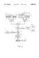
- FIG. 1is a block-diagram of one embodiment of the combinatorial screening apparatus of the present invention.
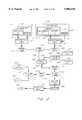
- FIG. 2is a block-diagram of a positive pressure fluidic system which may be used in a combinatorial screening apparatus of the present invention.
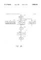
- FIG. 3is a block-diagram of one embodiment of a preferred system which may be used in a combinatorial screening apparatus of the present invention.
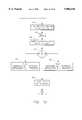
- FIG. 4represents a simplified algorithm of a screening mode which may be utilized in a combinatorial screening apparatus of the present invention.
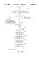
- FIG. 5represents a simplified algorithm for a potency mode which may be utilized in a combinatorial screening apparatus of the present invention.
- FIG. 6is a flow diagram of a preferred primary mode operation which may be implemented by a combinatorial screening apparatus of the present invention.
- FIG. 6comprises the combination of FIGS. 6a-6d
- FIG. 7is a flow diagram of a preferred screening mode operation which may be implemented by a combinatorial screening apparatus of the present invention.
- FIG. 7comprises the combination of FIGS. 7a-g.
- FIG. 8is a flow diagram of a preferred potency mode operation which may be implemented by a combinatorial screening apparatus of the present invention.
- FIG. 8comprises the combination of FIGS. 8a-e.
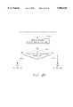
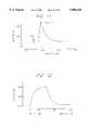
- FIG. 9represents the experimental results of ET-1 dose dependent Ca 2+ mobilization in the presence of BQ-123.
- FIG. 10represents the experimental results of dose dependent inhibition of ET-1 induced Ca 2+ mobilization in the TE-671 cells with BQ-123.
- FIG. 11represents the experimental results of ET-1 dose dependent Ca 2+ mobilization in TE-671 cells with the subsequent inhibition with the BQ-123
- FIG. 12illustrates the "null method” experimental results of ET-1 dose dependent Ca 2+ mobilization in TE-671 cells with subsequent inhibition with BQ-123.
- the present inventionprovides for real-time, continuous monitoring and detection of the physiological or pharmacological effect of a test compound on living cells.
- the present inventioncomprises a method and apparatus for continuously contacting a flow of suspended living cells with a predetermined concentration of at least one potentially active compound, preferably with predetermined concentrations of at least two active compounds. Then, intracellular changes that occur in response to contact between the cells and the active compounds are continuously measured as the flow of living cells and compounds passes a detector.
- the present inventionwill be of major value in highthroughput screening; e.g., in screening a large number of candidate compounds for activity. It has particular value, for example, in screening synthetic or natural product libraries for active compounds.
- a test compound, a standard compound, and a cell suspensionare continuously mixed together and, after an incubation period, are passed by a detector that measures the concentration in the cells or in the intracellular medium of at least one analyte.
- the concentration of the test compound and/or the standard compoundis varied over time to generate dose/response curves as output from the detector.
- the apparatus of the present inventionis under the control of a computer or other programmable controller.
- the controllercan continuously monitor the results of each step of the process, and can automatically alter the testing paradigm in response to those results.
- the incubation period after mixing of the compound or compounds and the cellscan advantageously be controlled by passing that mixture through a length of tubing connecting the mixing chamber with the detector.
- the incubation periodwill thus be determined by the flow rate and the length of the tubing.
- Incubation periodscan vary by several orders of magnitude, depending on the particular analyte and the resultant reaction time. For example, the incubation period could be as little as one second or a fraction of a second for rapid or short-lived physiological responses, or as long as several minutes or even hours.
- the analytecan be any analyte that is readily detectable by detectors and/or detector/chemistry combinations.
- various ion or electrolyte concentrations, colorimetric changes, optical density changes, fluorescence, luminescence, pH, gas production, and the likeare all readily adaptable for use in the present method and apparatus.
- calorimetric or fluorescent dyesare one particularly preferred embodiment.
- calcium ionis detectable by such probes as Fura-2, Indo-1, Fura Red or Quin-2, sodium ions by SBFL, proton ions by BCECF, SNAFL, DM-NERF, magnesium ions by Mag-Fura-2 or Mag-Fura-5, chloride ions by SPO, SPA or MOAE. All these dyes are commercially available, for example, from Molecular Probes, Inc., Oreg.
- FIG. 1illustrates a schematic configuration of a preferred embodiment of an apparatus of the present invention.
- the preferred embodimentconsists of a test compound sampler 101, for receiving and holding a sample of a compound to be tested; a standards sampler 103, for receiving and holding a sample of a standard solution (e.g., a buffer and/or a known agonist or antagonist) to be mixed with the compound to be tested; a concentration gradient device 105 connected to compound sampler 101 for controlling the flow volume of the compound to be tested; a concentration gradient device 107, connected to standards sampler 103, for controlling the flow volume of the standard solution; a switching valve 111 for receiving a compound/standard solution mixture or a calibration solution and for directing them to the mixing chamber 112 for mixing one of these solutions with a cell suspension; a cell suspension 113; a calibration unit 117, for supplying calibration solutions to the switching valve 111 so that the calibration solutions may be mixed with the cell suspension in predetermined ratios; a reaction developing lines unit 115, for receiving the cell suspension
- a controller 109is coupled to the test compound sampler 101, the standards sampler 103, gradient devices 105 and 107 and switching valve 111.
- the controllercontrols the above devices by receiving command signals from a computer 123 which in turn generates, sends and receives signals in accordance with a software program 125.
- reaction developing lines 115After a compound and/or standard is mixed with cells in mixing chamber 112, which is readily commercially available and in the preferred embodiment is the static mixer 125-1345 (Bio Rad), this mixture is then sent through reaction developing lines 115 so that it may be mixed more thoroughly and provided with enough time for its reagents to thoroughly react with one another.
- the detector 119is connected to the reaction developing lines unit 115, and receives the cell/compound/standard mixture from the reaction developing lines 115.
- each of the samplers 101 and 103include a sipper nozzle which may be positioned into a vial containing a respective compound or standard solution.
- samplersare well-known in the art and are readily available commercial products, e.g. A/S 300 Autosampler, Catalog # 15006330, Scientific Measurement Systems, Inc., Colo.
- A/S 300 AutosamplerCatalog # 15006330, Scientific Measurement Systems, Inc., Colo.
- conventional automated or robotic equipmentmay be used to supply the apparatus with the samples. Banks of different samples, arranged in 48 or 96 well plate format for example, can easily be accommodated by such automated sampling equipment.
- the gradient devices 105 and 107are also readily available commercial devices, e.g., GP40 Gradient Pump (Dionex). Depending on the mode of action, the corresponding concentration gradient devices 105 and 107 can prepare either discrete concentrations or continuous gradients of concentrations of the compound to be tested or the standard substance (agonist or antagonist) by diluting them with buffer. For example, if a continuous curve of cell response versus compound concentration in the presence of a standard substance is desired, the computer 123 will instruct the controller 109 to control the gradient devices 105 and 107 in such a way that continuous gradients of respective compound and a predetermined constant concentration of standard solution are provided to switching valve 111.
- GP40 Gradient PumpDionex
- the computer 123will instruct the controller 109 to control the gradient devices 105 and 107 such a way that continuous gradients of the respective standard solution and a predetermined constant concentration of the respective compound are provided to switching valve 111.
- the calibration unit 117connected to the switching valve 111, supplies calibration solutions needed to calibrate the output signal, MAX and MIN, of the apparatus.
- this calibration unitconsists of a diverting valve which is a readily available commercial device, e.g,. the SV3-2 Diverter Valve, (BioRad).
- the diverter valvealternates supply of two calibration solutions to the switching valve 111.
- the switching valve 111combines outflows from the gradient devices 105 and 107 or, alternatively, from the calibration unit 117 with a cell flow from a cell suspension reservoir 113 and directs the mixed flow into one of the reaction developing lines 115.
- the switching valve 111is of a type which is well-known in the industry and in a preferred embodiment is the 3-way microvalve 4-8-900 manufactured by General Valve Corp.
- the cell suspension reservoir 113is also of a type which is well known in the art and in a preferred embodiment is a regular glass beaker. Cells are maintained in suspension pending introduction into the device by simple low shear stirring.
- the reaction developing lines 115are typically tubes made from a non-corrosive material, having a specified diameter, through which the above mentioned mixture of cell suspension, compound and standard solution may flow.
- a non-corrosive materialhaving a specified diameter, through which the above mentioned mixture of cell suspension, compound and standard solution may flow.
- polyethylene, polypropylene, or polytetrafluoroethylene tubingcan be used. Tubing to which cells and other reagents will not stick is particularly preferred. The diameter of the tubing is a matter of choice. Capillary tubing having an inner diameter of from about 0.2 mm to about 2 mm is particularly advantageous, because it allows the use of very small sample sizes.
- This tubingis typically set in a winding configuration so that as the mixture flows through it, the mixture is thoroughly agitated and mixed. Even if the mixture is well mixed before introduction into the tubing, a spiral or wound configuration allows long tubing lengths in a compact area.
- reaction developing lines 115are commercially available and in one embodiment may be formed by Teflon tubing.
- reaction suspensionThe mixture of cell suspension and compound/standard solution, also referred to as "reaction suspension,” enters the detector's flow-through optical cell or other detection zone with a time delay or incubation period determined by the length of the reaction developing line 115.
- the detector 119can measure the cell suspension response to the specified concentration of the test compound.
- the detector 119measures a fluorescence signal from the calcium sensitive dye, FURA 2, spectral characteristics of which depend on a concentration of the intracellular ionized calcium, in order to determine the level of cell activity.
- the detector 119alternately irradiates the reaction suspension passing through a flow-through optical quvette, with the light of the wavelengths 340 nm and 380 nm and measures fluorescence intensity at 540 nm.
- the ratio (R) of the fluorescence intensities registered at 540 nm upon excitation at 340 nm and 380 nm, respectively,is transmitted to the computer 123.
- the computer 123calculates the concentration of the intracellular ionized calcium in accordance with the following equation which is well-known in the art:
- a computer 123connected to the detector 119, dictates its operation.
- the computer 123is also connected to or is a part of the controller 109 which controls the first and second gradient devices 105 and 107, switching valve 111 as well as test compound sampler 101 and standard sampler 103 in accordance with a software 125 implemented within the computer 123.
- the detector 119is capable of measuring the particular desired signal, whatever its origin.
- An optical detector 119may be a spectrophotometer, spectrofluorometer, or a luminometer, each of which have a flow-through optical cell. These devices are well-known in the art and are commercially available.
- one embodiment of the apparatus of the present inventionmay use an AMINCO-Bowman Series 2 Luminescence Spectrofluorometer (Fa-256, Spectronic Instruments, Inc.).
- the detectoris a direct ion measuring device, it can, for example, comprise a pH sensor or an ion selective electrode. Sodium, calcium, and potassium detectors are examples of such devices. Detectors of this type are commercially available. All of these devices can be controlled by means of a computer 123 during the data acquisition process.
- a positive pressure systemmay be created with piston pumps or other suitable pumps supplying reagents under positive pressure.
- a negative pressure systemmay be created with a peristaltic pump or other suitable pump drawing reagents through the system.
- the negative pressure systemis the simplest embodiment, because a large number of input sources can be driven by a single downstream pump.
- FIG. 2illustrates a schematic configuration of one embodiment of a positive pressure fluidic system.
- this systemoperates automatically under the control of a programmable controller, as will be explained in more detail below.
- This embodimentincludes an autosampler 201 which holds one or more compounds to be tested 203 and buffer 205 which may be mixed with the compound 203 in order to provide various concentrations of the compound 203; intake nozzles, or ports, 207 and 209 for receiving a compound and buffer, respectively and delivering the same to a gradient pump 211 which controls the concentration level and flow of a test compound 203 into a mixing chamber 227; an autosampler 213 which holds one or more standards (i.e., antagonists 215 and/or agonists 217) and a buffer 219 which may be mixed with the standard 215 or 217, in order to provide various concentrations of the standard; intake nozzles, or ports, 221 and 223, for receiving a standard and buffer, respectively, and providing the same to a gradient pump 225 which controls the concentration level and
- Each of the gradient pumps, 211 and 225may advantageously have two inlet tubing lines and one outlet tubing line, the outlet tubes being connected to each other through the mixing chamber 227.
- a controller(109 of FIG. 1) which is not shown in FIG. 2 controls the operation of autosamplers 201 and 213 and gradient pumps 211 and 225 by supplying remote signals to start/stop the pumping.
- gradient pumps 211 and 225may be the GP 40 Gradient Pump manufactured by Dionex.
- the mixing chamber 227receives the compound solution flowing through gradient pump 211 and, optionally, a standard solution flowing through the gradient pump 225, and mixes the compound and standard substances together.
- a diverting valve 235alternates the supply of either the calibration solution for maximal response 233 or the calibration solution for minimal response 237.
- the diverting valve 235preferably includes two inlet tubes, one tube for each of the two different calibration solutions 233, 237, and one outlet tube connected to a pump 231.
- the diverting valve 235is well-known in the art and can be implemented by the SV-3 Diverter Valve (BioRad).
- the controller(109 of FIG. 1) which is not shown in FIG.
- the pump 231for supplying calibration solutions to the fluidic system is also shown in FIG. 2.
- the pump 231receives either the calibration max. solution 233 or the calibration min. solution 237 from diverting valve 235 and then pumps the received calibration solution to switching valve 229.
- the outlet tube of pump 231is connected to an input of the switching valve 229.
- the pump 231is advantageously a standard piston pump which is well-known in the art.
- the pump 231is the series 1350 Soft-Start Pump (BioRad).
- the switching valve 229alternates the supply of either the compound/standard mixture or one of the calibration solutions to a mixing chamber 239.
- a pump 241supplies cells from cell suspension 243 to the mixing chamber 239.
- the pump 241receives cells from cell suspension 243 from an inlet tube and pumps the received cells through an outlet tube to one intake of the mixing chamber 239.
- the compound/standard solutions or calibration solutionscome through another intake of mixing chamber 239.
- Both mixing chambers 227 and 239,are well known in the art and in a preferred embodiment may be implemented by the Static Mixer, 125-1345 (BioRad).
- the pump 241can be a standard piston pump which is well-known in the art. In a preferred embodiment, the pump 241 is the series 1350 Soft-Start Pump (BioRad). The mixture of cells and compound/standard solution or cells and a calibration solution is then fed from mixing chamber 239 to reaction developing lines 245.
- the length of these linesdetermines the incubation period; i.e., the time elapsed from the point where the cells are mixed with the compound/standard mixture or the calibration mixture to the point of reaching detector 247.
- the detector 247measures the amount of cell response due to the compound/standard mixture or the calibration solution. After the cell response has been measured by detector 247, the mixture is then drained from the detector via drain 249.
- FIG. 3illustrates a schematic configuration of a preferred embodiment of the negative pressure fluidic system.
- one preferred embodimentincludes an autosampler 301 which holds one or more compounds (N i ) 303 and a buffer 305, the autosampler 301 further including two intake nozzles, or ports, 307 and 309, for receiving the compound (N i ) 303 and buffer 305, respectively; a proportionating valve 311 for preparing dilutions of the compound 303 with the buffer 305 in predetermined or specified proportions and delivering this mixture to a priming valve 313; an autosampler 315 which holds standard antagonists (M j ) 317 agonists (L k ) 319 and the buffer 305, the autosampler 315 further including two intake nozzles 323 and 325 for receiving the standard and the buffer, respectively; a proportionating valve 327 for preparing dilutions of the standard substance 317 or 319 with buffer 305 in predetermined or specified proportions and delivering this mixture
- the proportionating valves 311 and 327may be of any type which is well-known in the art. In a preferred embodiment these valves 311 and 327 are the series 4 miniature solenoid type valves (4-8-900 General Valve Corp.) working in a proportioning frequency mode. Similarly, priming valves 313 and 329 may be of any "normally opened” type which is well-known in the art and, in a preferred embodiment, are the series 4 miniature solenoid type valves (4-39-900) manufactured by General Valve Corp.
- a mixing chamber 331mixes a compound solution received from priming valve 313 and a standard solution received from priming valve 329.
- the first mixing chamber 331can constitute a simple "Y" connector; a chamber having a diameter several times that of the tubing; a length of tubing; a serpentine, baffled chamber; a chamber containing a mechanical rotating mixer; or any other suitable structure.
- the methodwill involve very small quantities of liquid (e.g., a full concentration gradient run can be accomplished with as little as 0.3 ml of sample).
- the volumes to be mixedare small and the mixing chamber should have small internal volume and high mixing efficacy.
- These types of mixersare well known in the art and in a preferred embodiment may be implemented by the Visco Jet® Micro-Mixer (#TCMA0120113T) manufactured by The Lee Company.
- a diverting valve 335alternates the supply of either a calibration solution for maximal response 337 or a calibration solution for minimal response 339.
- the diverting valve 335includes two inlet tubes for receiving the two different calibration solutions and one outlet tube connected to another diverting valve 333.
- the diverting valve 333can have two inlet tubes, one for receiving a compound/standard solution mixture and the other for receiving one of the calibration solutions 337 or 339.
- the diverting valve 333then alternates the supply of either the compound/standard mixture or one of the calibration solutions through an outlet tube to a priming valve 341 which then delivers the received fluid to a mixing chamber 343.
- a third diverting valve 347alternates the supply of either cells from a cell suspension 349 or the buffer solution 305 through an outlet tubing 346 to a priming valve 345 which then delivers either the cells or buffer to the mixing chamber 343 where it is mixed with either a compound/standard mixture or one of the calibration solutions received from priming valve 341.
- the diverting valves 333, 335 and 347may be of any type which is well known in the art, for example, a SV-3 Diverter Valve (BioRad).
- This mixtureis then sent to reaction developing lines 353 which determine the time elapsed from the point where the cells are mixed with the compound/standard mixture or one of the calibration solutions to the point where the mixture reaches the detector optical cell 355.
- the reaction developing lines 353 and the detector 355may be of any type which are well-known in the art.
- a peristaltic pump 357used as a negative pressure pump, can advantageously supply the necessary pressure required to make the various solutions and mixtures described above flow through the various valves (311, 313, 327, 329, 333, 335, 341, 345 and 347) mixing chambers (331 and 343), the reaction developing lines 353, the detector 355, and fmally to the drain 359.
- Suitable peristaltic pumps 357are well-known in the industry and in a preferred embodiment may be implemented by a EP-1 Econo Pump (BioRad).
- the pumps, valves, detectors, and other active components of the systemare preferably under the automated control of a programmable controller, as explained in more detail below.
- the apparatus in the present inventionpreferably has two primary modes of action, a screening mode and a potency mode.
- FIG. 4shows an algorithm that may be used in the invention to detect cell response during the screening mode.
- a cell/compound mixtureis provided to a detector (step 401).
- the apparatusdetermines if the compound, upon contact with the cells, triggers any cell response (step 403).
- the compounddoes not produce any response (NO), or it induces the cell response (YES).
- Cell responseis determined by monitoring the signal from the detector for the particular analyte being detected.
- the control systemfirst calibrates to establish a baseline and a maximal response, and any signal from the detector falling between those values is considered to be a positive response.
- the cellsare successively and automatically brought into contact with a mixture of the compound and the standard substances from a predetermined set of agonist solutions (step 407).
- Each solution in the setcontains one or more ingredients that initiates cell response in the absence of the test compound, e.g., through the stimulation of a known cell receptor, ion pump or ion channel molecules.
- a determinationis made as to whether a cell response normally triggered with a particular agonist is suppressed by the particular compound (step 411).
- the apparatuswill keep repeating an admixture of different standard agonist substances with the compound until it detects that the cell response triggered with a particular standard agonist is suppressed in the presence of the compound, or until all agonists available to the machine have been tested. If in step 411, it is determined that a cell response normally triggered with a particular agonist is suppressed by the particular compound (YES), that compound is categorized as an antagonist to the receptor Ri (step 415). After this happens, the instrument is switched over to the potency mode of action if instructed by the software managing the apparatus' performance (step 417).
- the cellsare automatically brought into contact with successive mixtures of the compound and the standard substance from a predetermined set of antagonist solutions (step 405).
- Each solution in the antagonist setcontains one or more ingredients that block the cell response initiated by at least one known agonist through the stimulation of a known cell receptor, ion pump or ion channel molecules.
- a determinationis made as to whether a cell response triggered with the compound is suppressed in the presence of a particular standard antagonist (step 409).
- the apparatuswill keep repeating an admixture of different standard antagonist substances with the compound until it detects that the cell response triggered with the compound is suppressed in the presence of particular standard antagonist, or until all the antagonists have been tested. If it is determined in step 409, that a cell response triggered with the compound is suppressed by the particular antagonist (YES), that compound will be characterized as an agonist to the receptor Ri (step 413). After this happens, the instrument is switched over to the potency mode of action if instructed by the software managing the apparatus' performance (step 417).
- the following receptor subtype specific antagonistsmay be used: BQ-123, BQ-788, BQ-153, BQ-485, BMS-182874 PD 151, 242, and the following receptor subtype specific agonists may be used: endothelin-1, endothelin-2, and endothelin-3. Sarafotoxin S6c, IRL 1620, BQ-3020.
- agonists of intracellular calcium channelsare: Ins (1,4,5)P 3 , Ryanodine, Caffeine, Heparine, Perchlorate, and their antagonists are: Decavanadte, Ruthenium Red and high concentrations of Ryanodine
- the screening modeis used for the characterization of the cell receptor pattern, commonly known as "receptor fingerprinting".
- a particular cell lineis screened against standard substances from a predetermined set of agonist solutions. Each solution in the set contains one or more ingredients that initiates cell response through the stimulation of a known cell receptor.
- the instrumentis switched over to the potency mode of action if instructed by the software managing the apparatus' performance.
- FIG. 5shows one algorithm that may be used in the invention in the preferred potency mode.
- the first step in the potency modeis to determine whether a particular compound has been categorized as an agonist or antagonist (step 501).
- the apparatusthen prepares continuous concentration gradients of either the standard substance or the compound being tested.
- the apparatuswill measure and register the concentration dependence of cell response (step 503). During step 503, the apparatus will generate continuous experimental activation curves for the activatory compound. From these curves, one can calculate the potency of the compound in terms, for example, of EC 50 (the effective concentration of an activator which causes 50% of the maximal stimulatory response of the cells) (step 505). This calculation can be performed using well known in the art curve fitting software. In a preferred embodiment this software may be implemented by the graphical software PRISM, manufactured by GraphPad, Inc.
- the apparatuswill measure and register the concentration dependence of cell response inhibition in the presence of a standard agonist (step 507).
- the apparatuswill generate continuous experimental inhibition curves for the antagonist compound taken at constant concentrations of the standard agonist substance. From these curves, one can calculate the potency of the compound in terms, for example, of IC 50 (the effective concentration of a blocker which causes 50% of the maximal inhibitory response cells) (step 509).
- IC 50the effective concentration of a blocker which causes 50% of the maximal inhibitory response cells
- the apparatuswill also measure and register the concentration dependence of the cell response to a standard agonist substance in the presence of several concentrations of the antagonist compound (step 511). During step 511, the apparatus will generate a series of continuous experimental activation curves for the standard agonist substance taken at different discrete concentrations of the antagonist compound. The apparatus will then calculate the affinity and the potency of the compound in terms, for example, of pA 2 values and determine whether the antagonist is competitive or non-competitive (step 513).
- the pA 2 valueis proportional to a negative logarithm of the binding constant of a ligand/receptor complex and is a measure of the affmity of the ligand to the receptor: the bigger pA 2 value, the higher the compound's affinity to the receptor.
- pA 2 valuecan be calculated from the shift of the activation curves in the presence of different concentrations of the antagonist compound and can be implemented by the formula:
- Ris a ratio of equipotent concentrations of the standard agonist substance measured both in the presence of discrete concentration (B) of the antagonist compound and without the antagonist.
- the equipotent concentrations of the standard agonist substancecan be found from the PRISM software activation curves.
- the processis started when a computer prompts an operator to chose a mode of operation from a choice of three modes: system priming mode, screening mode and potency profiling mode.
- the first choiceis to perform system priming.
- the operatoris prompted to place the nozzles of intake ports 309, 325 and 351 into a reservoir 305 filled with a buffer, the nozzles of the intake ports 336 and 338 into reservoirs 337 and 339, respectively, filled with corresponding calibration solutions, and the nozzle of the intake port 348 into the reservoir 349 filled with a cell suspension.
- FIGS. 6a-6dA continuous flow diagram of a preferred system priming process is shown in FIGS. 6a-6d for the preferred negative pressure fluidics system presented in FIG. 3.
- the system priming programbegins from a start state 600 and enters state 602 where it sets all parameters to their initial values. These initial parameters include, but are not limited to, the internal initialization of software variables and subroutines.
- autosamplers 301 and 302position their corresponding intake nozzles 307 and 323 at "zero" position (Step 604).
- Each autosamplerin its "zero” position, contains a reservoir 305 filled with a washing buffer.
- the power supplywhich supplies power to proportioning valves 311 and 327 (FIG. 3), to diverting valves 333, 335 and 347 (FIG. 3), and to priming valves 313, 329, 341 and 345 (FIG. 3) is turned off.
- the priming valves, 313, 329, 341 and 345are normally opened in a non-powered state (off); the proportioning valves, 311 and 327, in the non-powered (off) state, connect their outlets 312 and 328 with respective "normally opened” intake ports, 309 and 325; and in the non-powered (off) state, the diverting valve 335 connects its common outlet 334 with the "normally opened” intake port 336, diverting valve 333 connects its common outlet 342 with the "normally opened” intake port 332, and diverting valve 347 connects its common outlet 346 with the "normally opened” intake port 348.
- peristaltic pump 357is started (Step 606) and priming valves 313 and 345 are turned on (Step 608).
- the priming valves 313 and 345are closed. This forces the buffer flow through tubing 325, outlet tubing 328 of proportioning valve 327, priming valve 329, mixing chamber 331, intake tubing 332 and outlet tubing 342 of the diverting valve 333, priming valve 341, mixing chamber 343, a reaction developing line 353, detector 355, pump 357 and then into a drain container 359.
- computer 123implements software code 125 to provide control signals to a controller 109 which controls the various valves, chambers etc. of the system. This control signal is delayed in order to provide adequate time for liquid to fill the fluidic lines (Step 610).
- the proportioning valve 327is turned on (Step 612). While proportioning valve 327 is in the powered state, the buffer located at "zero" position of the autosampler 315 will flow through tubing 323, outlet tubing 328 of proportioning valve 327, priming valve 329, mixing chamber 331, intake tubing 332 and outlet tubing 342 of diverting valve 333, priming valve 341, mixing chamber 343, a reaction developing line 353, detector 355, pump 357 and then into a drain container 359.
- Step 613After energizing the proportioning valve 327, the control signal is delayed again (Step 613) in order to provide the time needed for the buffer to fill out the fluidics system.
- the control signalwill set the proportioning valve 327 to its off position (Step 614), turn off (open) priming valve 313 (Step 616) and turn on (close) the priming valve 329 (Step 618). This will fill out fluidic lines 309, 312, 332, 342, priming valve 341, mixing chamber 343, a reaction developing line 353, detector 355 and pump 357 during a delay (Step 619) which is needed for the lines to be filled with buffer 305.
- Step 620the proportioning valve 311 is powered (Step 620) for a time duration controlled by Step 621. During this delay period, the same fluidic lines are being fed with the buffer located at "zero" position of the autosampler 301, coming through the nozzle 307.
- Step 621the control signal simultaneously turns off both proportioning valve 311 (Step 622) and priming valve 329 (Step 624) and turns on both diverting valve 335 and diverting valve 333 (Step 626).
- Step 627the liquid flow will be directed from intake tubing 338 and outlet tubing 334 of the diverting valve 335 through the intake tubing 340 and the outlet tubing 342 of the diverting valve 333 through the priming valve 341, the mixing chamber 343 and further through the reaction developing line 353, the detector 355, the pump 357 and then to the drain container 359.
- the control signalturns off diverting valve 335 (Step 628), which allows the same fluidic lines to be fed from intake tubing 336.
- the length of time requiredis a function of the length of the different lines involved and the rate of fluid flow through the system, which for any particular system can be readily determined.
- the control signalturns off diverting valve 333 (Step 630), turns off (opens) priming valve 345 (Step 632) and turns on (closes) priming valve 341 (Step 634).
- the liquid flowwill be directed from the intake tubing 348 to outlet tubing 346 of diverting valve 347, through the priming valve 345, the mixing chamber 343, the reaction developing line 353, the detector 355, the pump 357 and then to the drain container 359.
- the time required for the above liquid flow to occuris provided by a delay period in Step 635.
- the control signalturns on diverting valve 347 (Step 636), which allows the same fluidic lines to be filled with the buffer 309 coming from tubing 351, during a delay period provided in Step 637.
- Step 637the control signal turns off (opens) priming valve 341 (Step 638), and turns off the diverting valve 347 (Step 640).
- the control signalthen turns off pump 357 (Step 642).
- the priming programends the system priming mode and all components of the fluidics system are filled with liquids (Step 643).
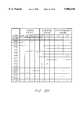
- Priming valves 345, 341, 313 and 329are of a two-way normally opened type.
- Diverting valves 335, 333 and 347are of a three-way type with one common outlet port and one each normally opened and normally closed intake ports.
- Proportionating valves 311 and 327are also of the three-way type similar to diverting valves 335, 333 and 347.
- the symbols "-" and “+”indicate turned off and turned on state of the valves.
- the state of all the valves after the priming mode is finishedis the same as at the initial state.
- the operatoris prompted to start either the screening or potency profiling mode. If screening mode is chosen, the operator is prompted to specify how many compounds are located in the set of compounds to be tested, N max , and how many antagonists, M max , and agonists, L max , solutions are located in the respective sets of the standards. If potency profiling mode is chosen, the operator is prompted to specify which compounds in a set should be measured.
- FIGS. 7a-7gA continuous flow diagram of the presently preferred screening mode with the negative pressure fluidics system of FIG. 3 is shown on FIGS. 7a-7g.
- the screening programbegins from a start state 700 and enters state 702 where it sets all parameters to their initial values. These initial parameters include, but are not limited to, the internal initialization of software variables and subroutines.
- the autosamplers 301 and 315position the intake nozzles 307 and 323 at the corresponding "zero" position occupied by a wash buffer reservoir 305 (Step 704), and turns off proportioning valves 311 and 327, diverting valves 333, 335 and 347, and priming valves 313, 329, 341 and 345 (Step 706).
- priming valves 313, 329, 341 and 345are normally opened, proportioning valves 311 and 327 connect, respectively, their outlets 312 and 328 with corresponding "normally opened” intake ports 309 and 325, diverting valve 335 connects its common outlet 334 with "normally opened” intake port 336, diverting valve 333 connects its common outlet 342 with the "normally opened” intake port 332, and diverting valve 347 connects its common outlet 346 with the "normally opened” intake port 348.
- pump 357is started (Step 708). This will force the wash buffer from the "zero" positioned reservoirs of both autosamplers 301 and 315 to run through nozzles 309 and 325 and outlet ports 312 and 328 of proportioning valves 311 and 327, respectively, priming valves 313 and 329, mixing chamber 331, intake port 332 and outlet port 342 of diverting valve 333, priming valve 341, mixing chamber 343, a reaction developing line 353, detector 355, pump 357 and then into a drain container 359. In mixing chamber 343 this flow is mixed with cell suspension 349 coming from intake tubing 348 and an outlet port 346 of diverting valve 347 through priming valve 345.
- the total flow passing mixing chamber 343is a sum of three flows, one of each coming from the proportioning valves 311 and 327 and one coming from diverting valve 347.
- both proportioning valvessupply wash buffer 305 from the reservoirs located at "zero" position of each autosampler in such a way that the final mixture consists of one part cell suspension 349 and two parts wash buffer 305.
- detector 355registers a basal signal produced by the cells alone, BS (Step 710). After the BS signal is registered, it is saved as a reference (Step 712) and computer 123 (FIG. 1) triggers incremental counter N (Step 714).
- the numerical content of the incremental counter Nis increased by unity each time it is triggered thus determining the position of the nozzle of intake port 307 of autosampler 301 which samples the sets of compounds 303 to be tested.
- the numerical content, N iof the incremental counter is checked against an entered maximum number of the compounds to be tested, N max (Step 716). If N i does not exceed N max , autosampler 301 positions nozzle 307 into the compound reservoir located at the N i position of a rack of compounds 303.
- proportioning valve 311is switched on to open its "normally closed" intake port 307 to the common output port 312 (Step 720).
- Step 720the combined flow in mixing chamber 343 and afterwards in detector 355, is composed of one portion of buffer 305 coming through nozzle 325 of proportioning valve 327, one portion of the compound 303 to be tested coming from nozzle 307 of proportioning valve 311 and one portion of cell suspension 349 coming from the intake tubing 348 which is "normally opened” to the output port 346 of diverting valve 347.
- detector 355registers a signal, SN i , produced by the cells in the presence of the given compound, N i (Step 722). After the SN i signal is registered, its value is saved as a reference value (Step 723).
- the value of the SN i signalis then compared with the value of the reference basal signal, BS (Step 724). If the SN i signal is greater than the BS signal, the computer 123 (FIG. 1) will "flag” the corresponding compound as "positive” (Step 725), which means that the compound stimulates the cell signal. If SN i is greater than BS, the computer 123 controls a set of antagonists and calculates corresponding coordinates for positioning the nozzle 323 of autosampler 315 over the antagonist containing reservoirs located in rack 317. If SN i is less than BS, computer 123 will "flag” the corresponding compound as "negative” (Step 726). In this case, the computer 123 controls a set of agonists and calculates corresponding coordinates for positioning the nozzle 323 of autosampler 315 over the agonist containing reservoirs located in rack 319.
- Step 730Each time the condition, "SN i >BS", is satisfied, the program flow will go through loop K-O of the incremental counter M (Step 730).
- the incremental counter, Mincreases the count number by one each time it is triggered and thus determines the successive positions of nozzle 323 of autosampler 315 which serves the set of standard antagonists located on rack 317.
- computer 123checks if the numerical content of the incremental counter (M j ) exceeds the maximun number of standards to be tested (M max ) entered by the operator (Step 732).
- Step 734If M j is less than or equal to M max , autosampler will position nozzle 323 into the standard antagonist reservoir, located on rack 317 corresponding to the numerical content of the incremental counter, M j (Step 734).
- proportioning valve 327is switched over to connect its "normally closed” intake port 323 with the outlet port 328 (Step 736).
- Step 736the combined flow through mixing chamber 343, reaction developing lines 353 and detector 355 is composed of one portion of standard antagonist coming from proportioning valve 327, one portion of the compound to be tested, coming from proportioning valve 311 and one portion of the cell suspension coming from diverting valve 347.
- detector 355registers and saves (Step 738) for further comparison, a signal, SN i M j , produced by a given compound, N i , in the presence of a given standard antagonist, M j .
- both proportioning valves 311 and 327are turned off (step 740). This closes intake ports 307 and 323 and opens intake ports 309 and 325 to the corresponding outlet ports 312 and 328.
- Autosampler 315then positions nozzle 323 into "zero" position occupied by wash buffer reservoir 305.
- the proportioning valve 327is then turned on again to open its "normally closed” intake port 323 into the outlet port 328 (Step 744) and the content of nozzle 323 is washed out (Step 746). Next, proportioning valve 327 is turned off to close intake port 323 and to open "normally opened” intake port 325. During this process, the fluidic lines are washed with buffer coming from nozzle 325 of autosampler 315.
- Computer 123compares signal, SN i , measured in the presence of a compound N i alone, with the signal, SN i M j , measured in the presence of both a compound N i and a standard antagonist, M j (Step 750). If the signal in the presence of a standard antagonist, M j , is lower than the signal generated by a compound N i alone, SN i M j ⁇ SN i , then both the compound N i and the standard antagonist, M j , is flagged as "positive” (Step 751). If both signals are equal to each other, then the compound N i is flagged as "positive” and the standard antagonist M j is flagged as "negative” (Step 752).
- Step 753After the data is flagged, the data, containing the ID number of the compound N i with its flag value and ID number of the standard antagonist M j with its flag value is transferred into a database (Step 753). After the data is saved the program loops back to trigger the incremental counter M (Step 730), to increase its count by one and Step 754 is repeated until the condition 732 is achieved.
- Step 732When the condition determined in the decision step 732 is met, that is the compound has been tested against all standard antagonists in a given set, the program resets the content of incremental counter M to zero (Step 755), and both autosampler 301 and autosampler 315 position their respective nozzles 307 and 323 to "zero" position, where the reservoirs with a washing buffer 305 are located (Step 756).
- both proportioning valves 311 and 327are turned on (Step 758). This opens “normally closed” intake ports 307 and 323 to the corresponding outlet ports 312 and 328. During this washing delay period determined by Step 760, the contents of both nozzle 312 and nozzle 328 are washed out with buffer 305.
- Step 760both proportioning valves 311 and 327 are turned off (Step 762).
- the programloops back to the incremental counter N content of which is incremented by one (Step 714) by triggering signal S tr from the computer 123 (FIG. 1). Then, the numerical content N i of counter N is compared with the maximum number, N max , of the compounds to be tested. If N i exceeds N max , the content of incremental counter N is zeroed (Step 717) and the screening mode is stopped (Step 719). Otherwise, Step 715 will be repeated with the next compound.
- Step 726If the condition of the decision process 724, SN i >BS, is not satisfied, the N i compound is flagged as "negative” (Step 726) and the incremental counter L is triggered (Step 764).
- the incremental counter Lis increased by one (Step 764) each time it is triggered and thus determines the successive positions of nozzle 323 of autosampler 315 relative to the set of standard agonists located on rack 319.
- the numerical content, L kof incremental counter L is compared with the maximum number, L max , of standard agonists to be used (step 766).
- autosampler 315positions nozzle 323 into the standard agonist reservoir in rack 319, which corresponds to the numerical content, L k , of incremental counter L.
- proportioning valve 327is turned on to open its "normally closed” intake port 323 to outlet port 328 and proportioning valve 311 is turned off to close its intake port 307 and open intake port 309 to outlet port 312 (Step 770).
- step 770the combined flow coming through mixing chamber 343, reaction developing lines 353 and detector 355 is composed of one portion of standard agonist 319 coming from inlet port 323 of proportioning valve 327, one portion of buffer 305, coming from inlet port 309 of proportioning valve 311 and one portion of cell suspension 349 coming from the diverting valve 347.
- Step 772After a delay period provided by Step 772, which is needed for the mixing process to stabilize, a signal, SL k , produced by a given standard agonist, L k is registered and saved (Step 774).
- proportioning valve 311is turned on to open its "normally closed” intake port 307 to outlet port 312 (Step 776).
- Step 778A delay period needed for the mixing process to stabilize is provided in Step 778, after which a signal, SL k N i , is stimulated by a given standard agonist, L k , in the presence of a given compound, N i is registered and saved in (Step 780).
- both proportioning valves 311 and 327are turned off to close their respective "normally closed” intake ports 307 and 323 and to open intake ports 309 and 325 to the corresponding outlet ports 312 and 328 (Step 782).
- autosampler 315positions the nozzle of intake port 323 to its "zero" position which corresponds to washing buffer reservoir 305 (Step 784).
- the proportioning valve 327is turned on (Step 785).
- Step 787This opens the "normally closed” intake port 323 to the outflow port 328, and after some delay provided by step 786, which is needed for washing out the content of nozzle 323, the proportioning valve 327 is turned off (Step 787), and the two signals, SL k N i and SL k , are compared (Step 788).
- Step 790If SL k N i is less than SL k , then the corresponding standard agonist, L k , is flagged as "positive” (Step 790). If both signals are equal to each other, then the standard agonist, L k , is flagged as "negative” (Step 792). After the data is flagged, the data, containing the ID number of the compound N i with its flag value and the ID number of the standard agonist L k with its flag value is transferred into a database (Step 794). After the data is saved the program triggers the incremental counter L (Step 764) to increase its count by one and Step 796 is repeated until condition 766 is achieved.
- Step 766When the condition determined in Step 766 is met, that is the compound has been tested against all standard agonists in a given set, the content of incremental counter L is reset to zero (Step 755) and both autosampler 301 and autosampler 315 position their respective nozzles 307 and 323 to "zero" position where the reservoirs with washing buffer 305 are located (Step 756).
- the systemthen turns on both proportioning valve 311 and proportioning valve 327 to open "normally closed” intake ports 307 and 323 to the corresponding outlet ports 312 and 328 respectively (Step 758).
- Step 760the contents of both nozzle 307 and nozzle 323 are washed out with the buffer 305.
- both proportioning valves 311 and 327are turned off (Step 762) and incremental counter N is incremented by one (Step 714).
- the new triggered numerical content N i of the incremental counter Nis compared with the maximum number, N max , of compounds to be tested (Step 716). If N i , exceeds N max , the counter N is set to zero in step 717 and the screening mode is stopped (Step 719). Otherwise, the whole cycle will be repeated with a subsequent compound.
- Step 719the operator is prompted by the computer to choose either potency profiling mode or to repeat screening mode with a new set of compounds.
- FIGS. 8a-8eA continuous flow diagram of the presently preferred potency profiling mode with the negative pressure fluidics system of FIG. 3 is shown in FIGS. 8a-8e.
- the potency profiling programbegins from a start state 800 and enters state 802 where it sets all incremental counters, L, M, and N, to zero and sets all parameters to their initial values.
- This initial parametersinclude, but are not limited to, the internal initialization of hardware and software variables and subroutines.
- the incremental counter Nis started (Step 804), and its numerical content, N i , is compared with the maximum number, N max , of standards, entered by the operator before starting the program (Step 806). If N i exceeds N max , the incremental counter N is zeroed (Step 808), and the program stops (Step 810). Otherwise, the program will proceed by turning on pump 357 (Step 816).
- the nozzles 307 and 323 of autosamplers 301 and 315are in zero position, proportioning valves 311 and 327, priming valves 313, 329, 341, and 345, and diverting valves 335, 333, and 347 are turned off.
- the combined flow coming through mixing chamber 343, reaction developing lines 353 and detector 355is composed of one portion of buffer 305 coming from inlet port 309 of proportioning valve 311, one portion of buffer 305, coming from inlet port 325 of proportioning valve 327 and one portion of cell suspension 349 coming from the diverting valve 347.
- diverting valve 333is turned on (Step 820), opening "normally closed” intake port 340 into outlet port 342.
- the calibration max solution 337which determines maximum response, flows through tubing 336 which is connected to outlet tubing 334 of diverting valve 335, through intake port 340 of diverting valve 333, through priming valve 341 and then into mixing chamber 343, where it is mixed with cells coming from cell suspension 349, through intake tube 348 and outlet tube 346 of diverting valve 347, and then through priming valve 345 into the mixing chamber 343.
- the cells calibration max mixturewill then flow to developing lines 353, and then to detector 355.
- the maximum signalis measured and registered (Step 824).
- Diverting valve 335is then turned on (Step 832) which opens the "normally closed” intake port 338 to outlet port 334 which allows a calibration min solution 339 to flow through diverting valve 333, priming valve 341 and into mixing chamber 343 where it is mixed with cells coming from cell suspension 349, through intake tube 348 and outlet tube 346 of diverting valve 347, and then through priming valve 345, into mixing chamber 343.
- the cells/calibration min. mixturethen flows to developing lines 353 and then to detector 335.
- the minimal response signalis then measured and registered (step 836).
- both diverting valves 335 and 333are turned off (Step 844).
- step 844the combined flow coming through mixing chamber 343, reaction developing lines 353 and detector 355 is composed of one portion of buffer 305 coming from inlet port 309 of proportioning valve 311, one portion of buffer 305, coming from inlet port 325 of proportioning valve 327 and one portion of cell suspension 349 coming from the diverting valve 347. This is needed to wash out the remains of calibration solution from the fluidics line.
- the "flag" value of the compound, N iis checked (Step 812).
- step 850If the "flag" value of the N i compound is "positive”, then the system will go to step 850, otherwise it will go to step 876. If the "flag" value of the N i compound is "positive”, autosampler 301 will position nozzle 307 into a reservoir corresponding to the N i compound, located on rack 303 (Step 850).
- proportioning valve 311is operated in a gradient mode (step 852). In the gradient mode, the proportioning valve, 311, combines flows from two intake ports, 307 and 309, in such a way that the proportion of a N i compound flow and a buffer flow in an outlet port, 312, changes in time to create a discontinuous change of the compound concentration.
- Step 854the resulting dose response dependence of the signal is registered in Step 854 with the subsequent calculation of the activation parameters for the N i compound in Step 856 and then saving the data in a database (Step 858).
- Step 860an incremental counter of the standard antagonists, M, is started (Step 860) and the numerical content, M j , of the counter M is compared with the maximum value, M max , entered by the operator (Step 861). If the numerical value M j does not exceed M max , then the "flag" value of the M j standard is checked (Step 862). If the "flag" value of the M j standard is not “positive”, the incremental counter, M, is increased by one (Step 860), and the steps following Step 860 will be repeated as described above. If the "flag" value of the M j standard is "positive”, autosampler 315 positions nozzle 323 into the reservoir corresponding to the M j standard antagonist, located on rack 317 (Step 864).
- proportioning valve 311is turned on (Step 866).
- the proportioning valve 311opens its "normally closed" intake port 307 which is immersed, in Step 850, into a reservoir corresponding to the compound N i , so that the N i compound flows through the fluidics system and generates a signal when it is mixed with the cells 349, coming through intake tubing 348 and outlet tubing of diverting valve 347, priming valve 345 to mixing chamber 343 and further to developing line 353 and detector 355.
- proportioning valve 327is operated in a concentration gradient mode (Step 868).
- proportioning valve 327combines flows coming from the two intake ports, 323 and 325 into outlet port 328 in such a way that the proportion of a M j standard antagonist flow and a buffer flow changes in time to create a discontinuous change of the standard antagonist concentration. While the concentration is being changed in time, the fresh portions of the cells flow into mixing chamber 343 from cell suspension 349 and react with the mixture composed of the N i compound at constant concentration and the standard antagonist M j at the concentration different at any given time. The resulting dose response inhibition by the M j standard antagonist of the N i compound stimulated signal is registered in Step 870, with the subsequent calculation of the inhibition parameters for the M j standard antagonist in a Step 872 and saving the data in a database (Step 874).
- Step 871After the curve is registered in Step 870 both proportioning valves 311 and 327 are closed (Step 871) and the program flow returns to Step 860 where incremental counter M is incremented by one and the program returns to Step 861 where M j is compared to M max .
- Step 861When all of the standard antagonists M j are counted and those with "positive flags" are measured, the numerical value M j becomes greater than M max , and the decision process in Step 861 returns to Step 804 where the incremental counter N increases its numeric value by one. The value of N i is then compared to N max , the maximum number of compounds to be tested (Step 806). If N i exceeds N max , the incremental counter N is reset to zero (Step 808), and the program stops (Step 810).
- Step 812If, in Step 812, the flag value of the N i compound is determined to be "negative", a incremental counter L which counts the standards, L k , in a set of agonists, located in rack 319, is updated (Step 876). Next, the numerical value L k is compared with the maximum number, L max , of standard agonists entered by an operator (Step 877).
- Step 878the program will go to Step 878, where the "flagged" value of the L k standard is checked. If the flag value is not positive, the program returns to Step 876. If the flag value of the L k standard is positive, autosampler 301 positions its nozzle 307 into a corresponding reservoir containing the N i compound located in rack 303 (Step 880), autosampler 315 positions its nozzle 323 into a corresponding reservoir containing the L k standard agonist, located in rack 319 (Step 881).
- proportioning valve 327is activated (Step 882) and a dose response stimulation of a signal with the L k standard agonist is then registered (step 884).
- proportioning valve 327combines flows coming from the two intake ports, 323 and 325, into outlet port 328 in such a way that the proportion of a L k standard agonist flow and a buffer flow changes in time to create a concentration gradient of the standard agonist.
- Step 884the activation parameters are calculated (Step 892) and then saved in a database (Step 894).
- Step 886the concentration gradient mode of proportioning valve 311 is activated (Step 886).
- a dose response inhibition by the N i compound of the L k standard agonist stimulated signalis then registered (Step 888) with a subsequent calculation of the inhibition parameters in Step 896. This data is then saved in a database (Step 894).
- Step 890When the registration of the concentration dependence is finished both proportioning valves 311 and 327 are turned off (Step 890) to close their intake ports 307 and 323 and to open "normally opened" intake ports 309 and 325.
- the fluidics linesare washed with buffer 305 coming from nozzles 309 and 325 of autosamplers 301 and 315 through outlet ports 312 and 328 of proportioning valves 311 and 327, priming valves 313 and 329, mixing chamber 331, "normally opened” intake port 332 and outlet port 342 of diverting valve 333, "normally opened” priming valve 341, mixing chamber 343, developing line 353 and detector 355.
- the programreturns to Step 876, at which point the above cycle is repeated until all the standard agonists are counted, and those with a positive flag are measured, and the numerical value L k of the incremental counter becomes greater than the L max value, at which point, the program will return to Step 804.
- Step 804When all of the compounds N i are counted (Step 804) and tested, the N i number becomes greater than the N max value and the incremental counter N is reset to zero (Step 808) and the program stops (Step 810).
- Cells for use in the apparatuscan be selected for the presence of particular known receptors or for their ability to provide predetermined cellular responses to particular stimuli.
- a large number of such cellsare known.
- Example 1If one wishes to measure an intracellular ion concentration, for example, one can preincubate the cells with a dye or other detectable material having sensitivity to concentration of that particular ion. (An actual working example illustrating preparation of cells for detection of calcium ion is set forth in Example 1.)
- the cells of particular interestmay use a set of agonists known to exert their activity through Ca 2+ mobilization, to characterize the cells by what type of the receptors are expressed in these particular cells.
- This set of agonistsmay consist of acethylcholin, adrenaline, noradrenaline, 5-hydroxitriptamine, DOPA, NMDA, AMPA, Angiotensin II, Bradykinin, Bombesin, Opioid, Endothelin-1 Neuropeptide Y, TNF, PDGF, FGF and so on.
- TE-671 cellshuman medulloblastoma (ATCC CRL 8805), naturally express endothelin subtype A receptor ET A R.
- This receptorbelongs to the family of seven transmembrane-spaning G-protein coupled receptors and is known to activate calcium mobilization in the cell cytoplasm upon binding to its specific agonist endothelin-1, a 21-amino acid peptide.
- affinity of the agonist for the receptorconventional methods measure the physiological response of the cell in the presence of several concentrations of the agonist or antagonist (Sakamoto, A. et al., 1994, incorporated herein by reference).
- FIG. 9illustrates a measurement of the activation of intracellular calcium mobilization (Ca 2+ measured in nanomolar concentration) as a function of the concentration of endothelin-1 (ET-1, measured in picomolar concentration), using the apparatus and method of the present invention.
- the apparatuswas a negative pressure computer controlled unit as described above. This run was performed in the presence of several concentrations of ET A R specific competitive antagonist BQ-123 (shown in nanomolar concentration).
- TE-671 cellswere prepared for use in the cell physiometer of the present invention by growing them in a T75 flask until confluence. The growth media was decanted and the cells were washed twice with Dulbecco's phosphate buffered saline (DPBS) and supplemented with a fresh DPBS containing 2 ILM FURA-2 ⁇ M, which easily penetrates into cell cytoplasm and is hydrolyzed there with nonspecific esterases to form FURA 2, a dye which is sensitive to the ionized form of calcium. After 30 min incubation, the cells were supplemented with the equal volume of fresh DPBS and incubated for further 30 min.
- DPBSDulbecco's phosphate buffered saline
- ILM FURA-2 ⁇ MILM FURA-2 ⁇ M
- the cellsnow loaded with the dye, were detached from the flask bottom with 0.05% Trypsin-EDTA solution. The cells were then washed twice with DPBS, containing 0.1% soybean trypsin inhibitor, and resuspended in calcium-free, magnesium-free and phenol red-free Dulbecco's modified Eagle's medium (DMEM).
- DPBScontaining 0.1% soybean trypsin inhibitor
- DMEMDulbecco's modified Eagle's medium
- ET-1 solutionan agonistic test compound
- DPBS bufferin continuously changing proportion by the proportioning valve 311 and was directed through the proportioning valve 311, mixing chamber 331, diverting valve 333, and priming valve 341 into the mixing chamber 343, where it was mixed with a suspension of TE-671 cells to provide a final concentration of cells 4 ⁇ 10 5 cells/ml.
- BQ-123as a standard antagonist solution, was also directed to the mixing chamber 331 at a predetermined concentration prepared by mixing BQ-123 with DPBS in the proportioning valve 327, in a ratio of 1:1 with the ET-1 solution.
- the mixed flow of BQ-123 at constant concentration, and ET-1 at a continuously changing in time concentrationis mixed with cells 349 in a ration of 2:1. This gives three fold final dilution for each component of the flow passing through mixing chamber 343 and eventually, detector 355.
- the proportioning valve 327was programmed for the first, second and third runs to give final BQ-123 concentration of zero, 10 nM and 40 nM, respectively.
- the proportioning valve 311was preprogrammed to give a final concentration of ET-1 in each run from 0 to 100 pM. Changes in intracellular calcium ion concentration in the TE-671 cells passing through the detector 315, were measured in real time as a function of ET-1 concentration using fluorescent dye FURA-2 as described above..
- the flow rate and the length of the reaction developing linewere chosen so that the time interval from the point of mixing the cells with the compound to the point of signal detection in the flow-through optical cell was 40 seconds.
- the time required for the complete concentration gradient run to generate the curves in FIG. 9was five minutes using the present invention.
- FIG. 10is a logarithmic transformation of the data in FIG. 9, which is used in the art to calculate maximal cell response in the presence of antagonist as well as EC 50 value for agonist and pA 2 value for antagonist.
- the EC 50 value calculated from the activation curve without BQ-123is equal to 10 pM and one can see that the activation curves in FIG. 10 are parallel shifted to the right in the presence of BQ-123, which is known in the art as characteristic for competitive type of inhibition.
- the average pA 2 value calculated from the two different concentrations of BQ-123is equal to 7.96. This corresponds to inhibition constant, K 1 , for BQ-123 of 11 nM.
- the EC 50 and pA 2 valuesare in close agreement with the literature data (Masaki Ihara et al., 1992, is incorporated herein by reference).
- FIG. 11illustrates the inhibition of ET-1 induced intracellular calcium mobilization with BQ-123 in TE-671 cells.
- the same cell physiometer apparatus and cell preparation procedurewas used here as in Example 1.
- ET-1was introduced at a constant concentration from the "standard” sipper nozzle of the inventive apparatus and BQ-123 was introduced through the "compound” nozzle of the apparatus.
- the concentration runwas five minutes and the reaction time (from mixing to detection) was forty seconds.
- ET-1 solutionan agonist standard solution
- DPBS bufferDPBS buffer
- priming valve 329DPBS buffer
- mixing chamber 331diverting valve 333 and priming valve 341 and then into mixing chamber 343, where it was mixed with a suspension of TE-671 cells to provide a final concentration of cells of 4 ⁇ 10 5 cells/ml.
- DPB in volumetric ratio of 1:1 to ET-1 solutionwas directed through intake port 309 and outlet port 312 of proportioning valve 311, priming valve 313 to mixing chamber 331 and further through fluidics system to the detector 355.
- BQ-123as an antagonistic test compound, was directed from intake port 307 of proportioning valve 311, instead of DPBS, to the mixing chamber 331 at continuously changing concentrations prepared by mixing BQ-123 with DPBS in proportioning valve 311, through the system in a volumetric ratio of 1:1 with the ET-1 solution.
- mixing chamber 343the mixed flow of ET-1 at constant concentration, and BQ-123 at a continuously changing in time concentration was mixed with cells 349 in a ratio of 2:1. This gives three fold final dilution for each component of the flow passing through mixing chamber 343 and, eventually, detector 355.
- the proportioning valve 327was preprogrammed to give a final concentration of ET-1 of 40 pM at the detector.
- the proportioning valve 311was preprogrammed to give final concentration of BQ-123 from 0 to 300 nM. Changes in intracellular calcium ion concentration in the TE-6712 cells passing through the detector 355, were measured in real time as a function of BQ-123 concentration using fluorescent dye FURA-2 as described above.
- FIG. 12shows the "null method” experiment design (Lazareno & Birdsall, 1993, incorporated herein by reference). This example uses the same instrument and the same reagents as in Examples 1 and 2.
- a first concentration gradient of ET-1 coming from the "standard” nozzle 323 of the inventive apparatusis prepared with the buffer solution coming from the "compound” nozzle.
- the gradient device 1keeps the ET-1 concentration constant and gradient device 2 starts raising the concentration of the BQ-123 coming from the "compound” nozzle.
Landscapes
- Health & Medical Sciences (AREA)
- Life Sciences & Earth Sciences (AREA)
- Engineering & Computer Science (AREA)
- Immunology (AREA)
- Chemical & Material Sciences (AREA)
- Biomedical Technology (AREA)
- Molecular Biology (AREA)
- Hematology (AREA)
- Urology & Nephrology (AREA)
- Analytical Chemistry (AREA)
- General Physics & Mathematics (AREA)
- General Health & Medical Sciences (AREA)
- Pathology (AREA)
- Biochemistry (AREA)
- Physics & Mathematics (AREA)
- Cell Biology (AREA)
- Medicinal Chemistry (AREA)
- Microbiology (AREA)
- Biotechnology (AREA)
- Food Science & Technology (AREA)
- Tropical Medicine & Parasitology (AREA)
- Bioinformatics & Cheminformatics (AREA)
- Toxicology (AREA)
- Proteomics, Peptides & Aminoacids (AREA)
- Investigating Or Analysing Biological Materials (AREA)
- Measuring Or Testing Involving Enzymes Or Micro-Organisms (AREA)
- Investigating Or Analysing Materials By The Use Of Chemical Reactions (AREA)
- Investigating Or Analysing Materials By Optical Means (AREA)
- Apparatus Associated With Microorganisms And Enzymes (AREA)
- Measurement Of The Respiration, Hearing Ability, Form, And Blood Characteristics Of Living Organisms (AREA)
- Radio Relay Systems (AREA)
Abstract
Description
Ca.sup.2+ !=K.sub.d (R-R.sub.min)/R.sub.max -R)(I.sub.f /I.sub.b)
pA.sub.2-Log(R- 1)-Log B,
Claims (50)
Priority Applications (15)
| Application Number | Priority Date | Filing Date | Title |
|---|---|---|---|
| US08/691,356US5804436A (en) | 1996-08-02 | 1996-08-02 | Apparatus and method for real-time measurement of cellular response |
| DE69717632TDE69717632T2 (en) | 1996-08-02 | 1997-08-01 | DEVICE AND METHOD FOR REAL-TIME MEASUREMENT OF THE CELLULAR REACTION |
| JP50810598AJP3847791B2 (en) | 1996-08-02 | 1997-08-01 | Apparatus and method for measuring cellular response in real time |
| PCT/US1997/013602WO1998005959A1 (en) | 1996-08-02 | 1997-08-01 | Apparatus and method for real-time measurement of cellular response |
| US08/904,904US5919646A (en) | 1996-08-02 | 1997-08-01 | Apparatus and method for real-time measurement of cellular response |
| AU40505/97AAU4050597A (en) | 1996-08-02 | 1997-08-01 | Apparatus and method for real-time measurement of cellular response |
| EP97938099AEP0916094B1 (en) | 1996-08-02 | 1997-08-01 | Apparatus and method for real-time measurement of cellular response |
| CA002261740ACA2261740A1 (en) | 1996-08-02 | 1997-08-01 | Apparatus and method for real-time measurement of cellular response |
| AT97938099TATE229182T1 (en) | 1996-08-02 | 1997-08-01 | DEVICE AND METHOD FOR REAL-TIME MEASUREMENT OF CELLULAR RESPONSE |
| US09/317,793US6096509A (en) | 1996-08-02 | 1999-05-24 | Apparatus and method for compound profiling of living cells |
| US09/370,786US6280967B1 (en) | 1996-08-02 | 1999-08-05 | Cell flow apparatus and method for real-time of cellular responses |
| US09/568,778US6242209B1 (en) | 1996-08-02 | 2000-05-10 | Cell flow apparatus and method for real-time measurements of cellular responses |
| US09/627,642US6379917B1 (en) | 1996-08-02 | 2000-07-28 | Apparatus and method for real-time measurement of cellular response |
| US09/779,690US6558916B2 (en) | 1996-08-02 | 2001-02-07 | Cell flow apparatus and method for real-time measurements of patient cellular responses |
| US10/328,670US6958221B2 (en) | 1996-08-02 | 2002-12-23 | Cell flow apparatus and method for real-time measurements of patient cellular responses |
Applications Claiming Priority (1)
| Application Number | Priority Date | Filing Date | Title |
|---|---|---|---|
| US08/691,356US5804436A (en) | 1996-08-02 | 1996-08-02 | Apparatus and method for real-time measurement of cellular response |
Related Child Applications (1)
| Application Number | Title | Priority Date | Filing Date |
|---|---|---|---|
| US08/904,904Continuation-In-PartUS5919646A (en) | 1996-08-02 | 1997-08-01 | Apparatus and method for real-time measurement of cellular response |
Publications (1)
| Publication Number | Publication Date |
|---|---|
| US5804436Atrue US5804436A (en) | 1998-09-08 |
Family
ID=24776225
Family Applications (4)
| Application Number | Title | Priority Date | Filing Date |
|---|---|---|---|
| US08/691,356Expired - LifetimeUS5804436A (en) | 1996-08-02 | 1996-08-02 | Apparatus and method for real-time measurement of cellular response |
| US08/904,904Expired - LifetimeUS5919646A (en) | 1996-08-02 | 1997-08-01 | Apparatus and method for real-time measurement of cellular response |
| US09/317,793Expired - LifetimeUS6096509A (en) | 1996-08-02 | 1999-05-24 | Apparatus and method for compound profiling of living cells |
| US09/627,642Expired - LifetimeUS6379917B1 (en) | 1996-08-02 | 2000-07-28 | Apparatus and method for real-time measurement of cellular response |
Family Applications After (3)
| Application Number | Title | Priority Date | Filing Date |
|---|---|---|---|
| US08/904,904Expired - LifetimeUS5919646A (en) | 1996-08-02 | 1997-08-01 | Apparatus and method for real-time measurement of cellular response |
| US09/317,793Expired - LifetimeUS6096509A (en) | 1996-08-02 | 1999-05-24 | Apparatus and method for compound profiling of living cells |
| US09/627,642Expired - LifetimeUS6379917B1 (en) | 1996-08-02 | 2000-07-28 | Apparatus and method for real-time measurement of cellular response |
Country Status (8)
| Country | Link |
|---|---|
| US (4) | US5804436A (en) |
| EP (1) | EP0916094B1 (en) |
| JP (1) | JP3847791B2 (en) |
| AT (1) | ATE229182T1 (en) |
| AU (1) | AU4050597A (en) |
| CA (1) | CA2261740A1 (en) |
| DE (1) | DE69717632T2 (en) |
| WO (1) | WO1998005959A1 (en) |
Cited By (100)
| Publication number | Priority date | Publication date | Assignee | Title |
|---|---|---|---|---|
| US6150180A (en)* | 1996-06-28 | 2000-11-21 | Caliper Technologies Corp. | High throughput screening assay systems in microscale fluidic devices |
| US6242209B1 (en)* | 1996-08-02 | 2001-06-05 | Axiom Biotechnologies, Inc. | Cell flow apparatus and method for real-time measurements of cellular responses |
| US6287758B1 (en) | 2000-03-23 | 2001-09-11 | Axiom Biotechnologies, Inc. | Methods of registering trans-membrane electric potentials |
| WO2001090295A1 (en)* | 2000-05-19 | 2001-11-29 | Cytomation, Inc. | A rapid multi-material sample input system |
| WO2001098754A1 (en)* | 2000-06-22 | 2001-12-27 | Atto Instruments Llc | High efficiency cell analysis system and high throughput drug screening system |
| WO2001079522A3 (en)* | 2000-04-14 | 2002-03-28 | Caliper Techn Corp | Screening assay methods and systems using target pooling |
| US20020049544A1 (en)* | 2000-06-23 | 2002-04-25 | Cytokinetics, Inc. | Image analysis for phenotyping sets of mutant cells |
| US6379884B2 (en) | 2000-01-06 | 2002-04-30 | Caliper Technologies Corp. | Methods and systems for monitoring intracellular binding reactions |
| US20020115164A1 (en)* | 2000-11-13 | 2002-08-22 | Genoptix | Methods and apparatus for generating and utilizing a moving optical gradient |
| US20020119441A1 (en)* | 2000-12-18 | 2002-08-29 | Cytokinetics, Inc., A Delaware Corporation | Method of characterizing potential therapeutics by determining cell-cell interactions |
| US20020132316A1 (en)* | 2000-11-13 | 2002-09-19 | Genoptix | Methods and apparatus for sorting of bioparticles based upon optical spectral signature |
| US20020141631A1 (en)* | 2001-02-20 | 2002-10-03 | Cytokinetics, Inc. | Image analysis of the golgi complex |
| US20020154798A1 (en)* | 2001-02-20 | 2002-10-24 | Ge Cong | Extracting shape information contained in cell images |
| US20020181837A1 (en)* | 2000-11-28 | 2002-12-05 | Mark Wang | Optical switching and sorting of biological samples and microparticles transported in a micro-fluidic device, including integrated bio-chip devices |
| US6529835B1 (en) | 1998-06-25 | 2003-03-04 | Caliper Technologies Corp. | High throughput methods, systems and apparatus for performing cell based screening assays |
| US6558960B1 (en) | 1996-06-28 | 2003-05-06 | Caliper Technologies Corp. | High throughput screening assay systems in microscale fluidic devices |
| US6558916B2 (en) | 1996-08-02 | 2003-05-06 | Axiom Biotechnologies, Inc. | Cell flow apparatus and method for real-time measurements of patient cellular responses |
| US20030100997A1 (en)* | 2001-05-04 | 2003-05-29 | Dunnington Damien J. | Matrix assays in genomically indexed cells |
| US20030106945A1 (en)* | 2001-11-01 | 2003-06-12 | Andrew Eaton | Sample introduction system |
| US6589729B2 (en) | 2000-02-04 | 2003-07-08 | Caliper Technologies Corp. | Methods, devices, and systems for monitoring time dependent reactions |
| US6606622B1 (en) | 1998-07-13 | 2003-08-12 | James M. Sorace | Software method for the conversion, storage and querying of the data of cellular biological assays on the basis of experimental design |
| US6615141B1 (en) | 1999-05-14 | 2003-09-02 | Cytokinetics, Inc. | Database system for predictive cellular bioinformatics |
| US6632619B1 (en)* | 1997-05-16 | 2003-10-14 | The Governors Of The University Of Alberta | Microfluidic system and methods of use |
| US20030193984A1 (en)* | 2000-07-26 | 2003-10-16 | Mihrimah Ozkan | Manipulation of live cells and inorganic objects with optical micro beam arrays |
| US20030211009A1 (en)* | 2001-05-18 | 2003-11-13 | Buchanan Kris S. | Rapid multi-material sample input system |
| US6651008B1 (en) | 1999-05-14 | 2003-11-18 | Cytokinetics, Inc. | Database system including computer code for predictive cellular bioinformatics |
| US20030224436A1 (en)* | 1996-07-30 | 2003-12-04 | Nelson Robert J. | Microfluidic apparatus and method for enriching and analyzing biological cells |
| US20030228566A1 (en)* | 2002-06-11 | 2003-12-11 | Biotechplex Corporation | Method of and apparatus for screening for drug candidates |
| US20040053209A1 (en)* | 2002-09-12 | 2004-03-18 | Genoptix, Inc | Detection and evaluation of topoisomerase inhibitors using optophoretic analysis |
| US20040067167A1 (en)* | 2002-10-08 | 2004-04-08 | Genoptix, Inc. | Methods and apparatus for optophoretic diagnosis of cells and particles |
| US20040071328A1 (en)* | 2001-09-07 | 2004-04-15 | Vaisberg Eugeni A. | Classifying cells based on information contained in cell images |
| US6744038B2 (en) | 2000-11-13 | 2004-06-01 | Genoptix, Inc. | Methods of separating particles using an optical gradient |
| US6815664B2 (en) | 2001-04-27 | 2004-11-09 | Genoptix, Inc. | Method for separation of particles |
| US20050014217A1 (en)* | 2003-07-18 | 2005-01-20 | Cytokinetics, Inc. | Predicting hepatotoxicity using cell based assays |
| US20050014216A1 (en)* | 2003-07-18 | 2005-01-20 | Cytokinetics, Inc. | Predicting hepatotoxicity using cell based assays |
| US6900021B1 (en) | 1997-05-16 | 2005-05-31 | The University Of Alberta | Microfluidic system and methods of use |
| US20050137806A1 (en)* | 2003-07-18 | 2005-06-23 | Cytokinetics, Inc. A Delaware Corporation | Characterizing biological stimuli by response curves |
| US20050249635A1 (en)* | 2004-05-07 | 2005-11-10 | Novasite Pharmaceuticals, Inc. | Direct mixing and injection for high throughput fluidic systems |
| US20050249642A1 (en)* | 2004-05-07 | 2005-11-10 | Novasite Pharmaceuticals, Inc. | Sample analysis system employing direct sample mixing and injection |
| US20050273271A1 (en)* | 2004-04-05 | 2005-12-08 | Aibing Rao | Method of characterizing cell shape |
| US20050272073A1 (en)* | 2000-12-04 | 2005-12-08 | Cytokinetics, Inc., A Delaware Corporation | Ploidy classification method |
| US20050283317A1 (en)* | 2001-02-20 | 2005-12-22 | Cytokinetics, Inc., A Delaware Corporation | Characterizing biological stimuli by response curves |
| US20060000722A1 (en)* | 1996-06-28 | 2006-01-05 | Caliper Life Sciences, Inc. | High throughput screening assay systems in microscale fluidic devices |
| US20060014135A1 (en)* | 2004-07-15 | 2006-01-19 | Cytokinetics, Inc. | Assay for distinguishing live and dead cells |
| US7094527B2 (en) | 2000-11-29 | 2006-08-22 | Xy, Inc. | System for in-vitro fertilization with spermatozoa separated into X-chromosome and Y-chromosome bearing populations |
| US20060239329A1 (en)* | 2005-03-14 | 2006-10-26 | Kabushiki Kaisha Bio Echo Net | Ear-type clinical thermometer |
| US7169548B2 (en) | 2002-09-13 | 2007-01-30 | Xy, Inc. | Sperm cell processing and preservation systems |
| US20070031818A1 (en)* | 2004-07-15 | 2007-02-08 | Cytokinetics, Inc., A Delaware Corporation | Assay for distinguishing live and dead cells |
| US20070042433A1 (en)* | 2003-03-26 | 2007-02-22 | Jianxin Bao | Neuregulin protein regulation of synaptic proteins |
| US7195920B2 (en) | 1997-12-31 | 2007-03-27 | Xy, Inc. | Collection systems for cytometer sorting of sperm |
| US7208265B1 (en) | 1999-11-24 | 2007-04-24 | Xy, Inc. | Method of cryopreserving selected sperm cells |
| US7221453B2 (en) | 1997-01-31 | 2007-05-22 | Xy, Inc. | Optical apparatus |
| US20070178553A1 (en)* | 1997-02-28 | 2007-08-02 | Snutch Terrance P | Mammalian T-type calcium channels |
| US7297504B1 (en)* | 1997-02-28 | 2007-11-20 | Neuromed Pharmaceuticals Ltd. | Methods for identifying agonists and antagonists of human T-type calcium channels |
| US7371517B2 (en) | 2000-05-09 | 2008-05-13 | Xy, Inc. | High purity X-chromosome bearing and Y-chromosome bearing populations of spermatozoa |
| US7618770B2 (en) | 2005-07-29 | 2009-11-17 | Xy, Inc. | Methods and apparatus for reducing protein content in sperm cell extenders |
| US7629113B2 (en) | 1997-12-31 | 2009-12-08 | Xy, Inc | Multiple sexed embryo production system for bovine mammals |
| US7713687B2 (en) | 2000-11-29 | 2010-05-11 | Xy, Inc. | System to separate frozen-thawed spermatozoa into x-chromosome bearing and y-chromosome bearing populations |
| US7723116B2 (en) | 2003-05-15 | 2010-05-25 | Xy, Inc. | Apparatus, methods and processes for sorting particles and for providing sex-sorted animal sperm |
| US7745221B2 (en) | 2003-08-28 | 2010-06-29 | Celula, Inc. | Methods and apparatus for sorting cells using an optical switch in a microfluidic channel network |
| US7758811B2 (en) | 2003-03-28 | 2010-07-20 | Inguran, Llc | System for analyzing particles using multiple flow cytometry units |
| US7772005B1 (en) | 1998-07-30 | 2010-08-10 | Xy, Llc | Method of establishing an equine artificial insemination sample |
| US7833147B2 (en) | 2004-07-22 | 2010-11-16 | Inguran, LLC. | Process for enriching a population of sperm cells |
| US7838210B2 (en) | 2004-03-29 | 2010-11-23 | Inguran, LLC. | Sperm suspensions for sorting into X or Y chromosome-bearing enriched populations |
| US7855078B2 (en) | 2002-08-15 | 2010-12-21 | Xy, Llc | High resolution flow cytometer |
| US8105477B2 (en) | 2003-04-16 | 2012-01-31 | Handylab, Inc. | System and method for electrochemical detection of biological compounds |
| US8133671B2 (en) | 2007-07-13 | 2012-03-13 | Handylab, Inc. | Integrated apparatus for performing nucleic acid extraction and diagnostic testing on multiple biological samples |
| US8182763B2 (en) | 2007-07-13 | 2012-05-22 | Handylab, Inc. | Rack for sample tubes and reagent holders |
| US8211629B2 (en) | 2002-08-01 | 2012-07-03 | Xy, Llc | Low pressure sperm cell separation system |
| US8216530B2 (en) | 2007-07-13 | 2012-07-10 | Handylab, Inc. | Reagent tube |
| USD665095S1 (en) | 2008-07-11 | 2012-08-07 | Handylab, Inc. | Reagent holder |
| USD669191S1 (en) | 2008-07-14 | 2012-10-16 | Handylab, Inc. | Microfluidic cartridge |
| US8287820B2 (en) | 2007-07-13 | 2012-10-16 | Handylab, Inc. | Automated pipetting apparatus having a combined liquid pump and pipette head system |
| US8324372B2 (en) | 2007-07-13 | 2012-12-04 | Handylab, Inc. | Polynucleotide capture materials, and methods of using same |
| US8323900B2 (en) | 2006-03-24 | 2012-12-04 | Handylab, Inc. | Microfluidic system for amplifying and detecting polynucleotides in parallel |
| US8323584B2 (en) | 2001-09-12 | 2012-12-04 | Handylab, Inc. | Method of controlling a microfluidic device having a reduced number of input and output connections |
| US8415103B2 (en) | 2007-07-13 | 2013-04-09 | Handylab, Inc. | Microfluidic cartridge |
| US8420015B2 (en) | 2001-03-28 | 2013-04-16 | Handylab, Inc. | Systems and methods for thermal actuation of microfluidic devices |
| US8440149B2 (en) | 2001-02-14 | 2013-05-14 | Handylab, Inc. | Heat-reduction methods and systems related to microfluidic devices |
| US8470586B2 (en) | 2004-05-03 | 2013-06-25 | Handylab, Inc. | Processing polynucleotide-containing samples |
| US8473104B2 (en) | 2001-03-28 | 2013-06-25 | Handylab, Inc. | Methods and systems for control of microfluidic devices |
| US8486618B2 (en) | 2002-08-01 | 2013-07-16 | Xy, Llc | Heterogeneous inseminate system |
| USD692162S1 (en) | 2011-09-30 | 2013-10-22 | Becton, Dickinson And Company | Single piece reagent holder |
| US8617905B2 (en) | 1995-09-15 | 2013-12-31 | The Regents Of The University Of Michigan | Thermal microvalves |
| US8679831B2 (en) | 2003-07-31 | 2014-03-25 | Handylab, Inc. | Processing particle-containing samples |
| US8703069B2 (en) | 2001-03-28 | 2014-04-22 | Handylab, Inc. | Moving microdroplets in a microfluidic device |
| US8709787B2 (en) | 2006-11-14 | 2014-04-29 | Handylab, Inc. | Microfluidic cartridge and method of using same |
| US8852862B2 (en) | 2004-05-03 | 2014-10-07 | Handylab, Inc. | Method for processing polynucleotide-containing samples |
| US8883490B2 (en) | 2006-03-24 | 2014-11-11 | Handylab, Inc. | Fluorescence detector for microfluidic diagnostic system |
| US8895311B1 (en) | 2001-03-28 | 2014-11-25 | Handylab, Inc. | Methods and systems for control of general purpose microfluidic devices |
| US9040288B2 (en) | 2006-03-24 | 2015-05-26 | Handylab, Inc. | Integrated system for processing microfluidic samples, and method of using the same |
| US9186677B2 (en) | 2007-07-13 | 2015-11-17 | Handylab, Inc. | Integrated apparatus for performing nucleic acid extraction and diagnostic testing on multiple biological samples |
| US9222954B2 (en) | 2011-09-30 | 2015-12-29 | Becton, Dickinson And Company | Unitized reagent strip |
| US9618139B2 (en) | 2007-07-13 | 2017-04-11 | Handylab, Inc. | Integrated heater and magnetic separator |
| USD787087S1 (en) | 2008-07-14 | 2017-05-16 | Handylab, Inc. | Housing |
| US9765389B2 (en) | 2011-04-15 | 2017-09-19 | Becton, Dickinson And Company | Scanning real-time microfluidic thermocycler and methods for synchronized thermocycling and scanning optical detection |
| US10822644B2 (en) | 2012-02-03 | 2020-11-03 | Becton, Dickinson And Company | External files for distribution of molecular diagnostic tests and determination of compatibility between tests |
| US10900066B2 (en) | 2006-03-24 | 2021-01-26 | Handylab, Inc. | Microfluidic system for amplifying and detecting polynucleotides in parallel |
| US11453906B2 (en) | 2011-11-04 | 2022-09-27 | Handylab, Inc. | Multiplexed diagnostic detection apparatus and methods |
| US11806718B2 (en) | 2006-03-24 | 2023-11-07 | Handylab, Inc. | Fluorescence detector for microfluidic diagnostic system |
Families Citing this family (68)
| Publication number | Priority date | Publication date | Assignee | Title |
|---|---|---|---|---|
| US5989835A (en)* | 1997-02-27 | 1999-11-23 | Cellomics, Inc. | System for cell-based screening |
| US5804436A (en)* | 1996-08-02 | 1998-09-08 | Axiom Biotechnologies, Inc. | Apparatus and method for real-time measurement of cellular response |
| US6759206B1 (en) | 1997-02-27 | 2004-07-06 | Cellomics, Inc. | System for cell-based screening |
| US6727071B1 (en) | 1997-02-27 | 2004-04-27 | Cellomics, Inc. | System for cell-based screening |
| AU730100B2 (en) | 1997-02-27 | 2001-02-22 | Cellomics, Inc. | A system for cell-based screening |
| US7853411B2 (en)* | 1997-02-27 | 2010-12-14 | Cellomics, Inc. | System for cell-based screening |
| US7117098B1 (en) | 1997-02-27 | 2006-10-03 | Cellomics, Inc. | Machine-readable storage medium for analyzing distribution of macromolecules between the cell membrane and the cell cytoplasm |
| US6004025A (en)* | 1997-05-16 | 1999-12-21 | Life Technologies, Inc. | Automated liquid manufacturing system |
| US5891646A (en)* | 1997-06-05 | 1999-04-06 | Duke University | Methods of assaying receptor activity and constructs useful in such methods |
| US6528271B1 (en)* | 1997-06-05 | 2003-03-04 | Duke University | Inhibition of βarrestin mediated effects prolongs and potentiates opioid receptor-mediated analgesia |
| US7541151B2 (en) | 1997-06-05 | 2009-06-02 | Duke University | Single-cell biosensor for the measurement of GPCR ligands in a test sample |
| US6692696B1 (en)* | 1998-06-18 | 2004-02-17 | ARETé ASSOCIATES | Biosensor |
| US6132685A (en)* | 1998-08-10 | 2000-10-17 | Caliper Technologies Corporation | High throughput microfluidic systems and methods |
| US6673554B1 (en)* | 1999-06-14 | 2004-01-06 | Trellie Bioinformatics, Inc. | Protein localization assays for toxicity and antidotes thereto |
| US6716588B2 (en) | 1999-12-09 | 2004-04-06 | Cellomics, Inc. | System for cell-based screening |
| WO2001053534A2 (en)* | 2000-01-21 | 2001-07-26 | Curagen Corporation | Method of identifying the function of a test agent |
| WO2001089696A2 (en)* | 2000-05-24 | 2001-11-29 | Micronics, Inc. | Microfluidic concentration gradient loop |
| DE10028692C2 (en)* | 2000-06-09 | 2002-06-06 | Micronas Gmbh | Procedure for the investigation of membrane-enclosed biocompartments |
| DE10041596A1 (en)* | 2000-08-24 | 2002-03-21 | Cellcontrol Biomedical Lab Gmb | Device and method for the spatially resolved examination of networked cells and / or cell systems and use for the examination of active substances |
| US6913877B1 (en) | 2000-09-11 | 2005-07-05 | State Of Oregon Acting By And Through The State Board Of Higher Education On Behalf Of Oregon State University | Methods for detecting bioactive compounds |
| US6936811B2 (en)* | 2000-11-13 | 2005-08-30 | Genoptix, Inc. | Method for separating micro-particles |
| US20020123112A1 (en)* | 2000-11-13 | 2002-09-05 | Genoptix | Methods for increasing detection sensitivity in optical dielectric sorting systems |
| US20020160470A1 (en)* | 2000-11-13 | 2002-10-31 | Genoptix | Methods and apparatus for generating and utilizing linear moving optical gradients |
| US20030013137A1 (en)* | 2001-03-13 | 2003-01-16 | Barak Larry S. | Automated methods of detecting receptor activity |
| US20040009540A1 (en)* | 2001-04-27 | 2004-01-15 | Genoptix, Inc | Detection and evaluation of cancer cells using optophoretic analysis |
| US7695926B2 (en) | 2001-07-10 | 2010-04-13 | The Board Of Trustees Of The Leland Stanford Junior University | Methods and compositions for detecting receptor-ligand interactions in single cells |
| US7393656B2 (en)* | 2001-07-10 | 2008-07-01 | The Board Of Trustees Of The Leland Stanford Junior University | Methods and compositions for risk stratification |
| EP1415156B1 (en) | 2001-07-10 | 2009-09-02 | The Board Of Trustees Of The Leland Stanford Junior University | Methods and compositions for detecting the activation state of multiple proteins in single cells |
| US7381535B2 (en) | 2002-07-10 | 2008-06-03 | The Board Of Trustees Of The Leland Stanford Junior | Methods and compositions for detecting receptor-ligand interactions in single cells |
| DE60236159D1 (en)* | 2001-07-13 | 2010-06-10 | Caliper Life Sciences Inc | METHOD FOR SEPARATING COMPONENTS OF A MIXTURE |
| WO2003023366A2 (en)* | 2001-09-12 | 2003-03-20 | The State Of Oregon, Acting By And Through The State Board Of Higher Education On Behalf Of Oregon State University | Method and system for classifying a scenario |
| US20030182669A1 (en)* | 2002-03-19 | 2003-09-25 | Rockman Howard A. | Phosphoinositide 3-kinase mediated inhibition of GPCRs |
| US20030211461A1 (en)* | 2002-05-01 | 2003-11-13 | Genoptix, Inc | Optophoretic detection of durgs exhibiting inhibitory effect on Bcr-Abl positive tumor cells |
| US20040033539A1 (en)* | 2002-05-01 | 2004-02-19 | Genoptix, Inc | Method of using optical interrogation to determine a biological property of a cell or population of cells |
| US20040121474A1 (en)* | 2002-12-19 | 2004-06-24 | Genoptix, Inc | Detection and evaluation of chemically-mediated and ligand-mediated t-cell activation using optophoretic analysis |
| US20040121307A1 (en)* | 2002-12-19 | 2004-06-24 | Genoptix, Inc | Early detection of cellular differentiation using optophoresis |
| GB0307999D0 (en)* | 2003-04-07 | 2003-05-14 | Glaxo Group Ltd | A system |
| US20050148506A1 (en)* | 2003-04-16 | 2005-07-07 | Wyeth | Novel method of modulating bone-related activity |
| US7785843B2 (en)* | 2004-06-23 | 2010-08-31 | Sequenom, Inc. | Target-specific compomers and methods of use |
| US7595170B2 (en)* | 2004-08-05 | 2009-09-29 | Modrovich Ivan E | Apparatus and method for measuring concentrations of molecules through a barrier |
| AU2006206159A1 (en)* | 2005-01-24 | 2006-07-27 | Massachusetts Institute Of Technology | Method for modeling cell signaling systems by means of bayesian networks |
| DE102006011828A1 (en)* | 2006-03-13 | 2007-09-20 | Gesellschaft für Schwerionenforschung mbH | Irradiation verification device for radiation therapy equipment and method of handling the same |
| EP2021438A4 (en)* | 2006-06-01 | 2010-09-29 | Oregon State | MICRORACTOR PROCESS FOR MANUFACTURING BIODIESEL |
| GB0617035D0 (en) | 2006-08-30 | 2006-10-11 | Inverness Medical Switzerland | Fluidic indicator device |
| US20090287309A1 (en) | 2007-01-30 | 2009-11-19 | Tornier Sas | Intra-articular joint replacement |
| US20090186374A1 (en)* | 2008-01-23 | 2009-07-23 | Etogen Scientific | Apparatus for measuring effect of test compounds on biological objects |
| GB2474146B (en)* | 2008-04-29 | 2013-04-10 | Nodality Inc | Methods of determining the health status of an individual |
| US20090291458A1 (en)* | 2008-05-22 | 2009-11-26 | Nodality, Inc. | Method for Determining the Status of an Individual |
| US8227202B2 (en)* | 2008-07-10 | 2012-07-24 | Nodality, Inc. | Methods for diagnosis, prognosis and methods of treatment |
| US8399206B2 (en) | 2008-07-10 | 2013-03-19 | Nodality, Inc. | Methods for diagnosis, prognosis and methods of treatment |
| US20100099109A1 (en)* | 2008-10-17 | 2010-04-22 | Nodality, Inc., A Delaware Corporation | Methods for Analyzing Drug Response |
| USD685474S1 (en) | 2010-07-06 | 2013-07-02 | Tornier, Inc. | Prosthesis anchor |
| CN103140755B (en) | 2010-07-22 | 2016-03-16 | 哈希公司 | For the lab on A Chip of alkalinity analyzing |
| CN101963589B (en)* | 2010-08-19 | 2012-07-25 | 中国人民解放军第三〇二医院 | Method for detecting activity of antivirus medicament and application thereof |
| FR2978912A1 (en) | 2011-08-10 | 2013-02-15 | Tornier Inc | ANCILLARY EXTRACTION OF A PROSTHESIS |
| US9180449B2 (en) | 2012-06-12 | 2015-11-10 | Hach Company | Mobile water analysis |
| USD768872S1 (en) | 2012-12-12 | 2016-10-11 | Hach Company | Cuvette for a water analysis instrument |
| WO2015017798A2 (en)* | 2013-08-02 | 2015-02-05 | CRIXlabs, Inc. | Method and system for predicting spatial and temporal distributions of therapeutic substance carriers |
| US12023253B2 (en) | 2014-01-24 | 2024-07-02 | Howmedica Osteonics Corp. | Humeral implant anchor system |
| US10456264B2 (en) | 2014-01-24 | 2019-10-29 | Tornier, Inc. | Humeral implant anchor system |
| US10463499B2 (en) | 2016-03-25 | 2019-11-05 | Tornier, Inc. | Stemless shoulder implant with fixation components |
| US11129724B2 (en) | 2016-07-28 | 2021-09-28 | Howmedica Osteonics Corp. | Stemless prosthesis anchor component |
| MX2020003194A (en) | 2017-09-25 | 2020-12-09 | Howmedica Osteonics Corp | Patient specific stemless prosthesis anchor components. |
| US11399948B2 (en) | 2017-12-11 | 2022-08-02 | Howmedica Osteonics Corp. | Stemless prosthesis anchor components and kits |
| EP4257090A3 (en) | 2018-10-02 | 2023-12-13 | Howmedica Osteonics Corp. | Shoulder prosthesis components and assemblies |
| USD951449S1 (en) | 2019-10-01 | 2022-05-10 | Howmedica Osteonics Corp. | Humeral implant |
| EP4527357A3 (en) | 2019-10-01 | 2025-06-04 | Howmedica Osteonics Corporation | Shoulder prosthesis components and assemblies |
| JP2024099338A (en)* | 2023-01-12 | 2024-07-25 | 東京応化工業株式会社 | Tubes and cell culture devices |
Citations (24)
| Publication number | Priority date | Publication date | Assignee | Title |
|---|---|---|---|---|
| US3772154A (en)* | 1971-05-03 | 1973-11-13 | Technicon Instr | Method and apparatus for automated antibiotic susceptibility analysis of bacteria samples |
| US3826899A (en)* | 1969-08-15 | 1974-07-30 | Nuclear Res Ass Inc | Biological cell analyzing system |
| US4271123A (en)* | 1979-10-22 | 1981-06-02 | Bio-Rad Laboratories, Inc. | Automated system for performing fluorescent immunoassays |
| US4343782A (en)* | 1978-04-20 | 1982-08-10 | Shapiro Howard M | Cytological assay procedure |
| US4632808A (en)* | 1983-04-15 | 1986-12-30 | Science And Technology Agency | Chemical manipulator |
| US4676951A (en)* | 1985-07-01 | 1987-06-30 | American Hospital Supply Corp. | Automatic specimen analyzing system |
| US4678752A (en)* | 1985-11-18 | 1987-07-07 | Becton, Dickinson And Company | Automatic random access analyzer |
| US4766078A (en)* | 1985-03-07 | 1988-08-23 | Henry Gang | Automated consecutive reaction analyzer |
| WO1990004645A1 (en)* | 1988-10-21 | 1990-05-03 | Molecular Devices Corporation | Methods and apparatus for detecting the effect of cell affecting agents on living cells |
| WO1993013423A1 (en)* | 1991-12-20 | 1993-07-08 | The Salk Institute Biotechnology/Industrial Associates, Inc. | Automated analysis equipment and assay method for detecting cell surface protein and/or cytoplasmic receptor function using same |
| US5278048A (en)* | 1988-10-21 | 1994-01-11 | Molecular Devices Corporation | Methods for detecting the effect of cell affecting agents on living cells |
| US5320808A (en)* | 1988-08-02 | 1994-06-14 | Abbott Laboratories | Reaction cartridge and carousel for biological sample analyzer |
| US5401629A (en)* | 1990-08-07 | 1995-03-28 | The Salk Institute Biotechnology/Industrial Associates, Inc. | Assay methods and compositions useful for measuring the transduction of an intracellular signal |
| US5463564A (en)* | 1994-09-16 | 1995-10-31 | 3-Dimensional Pharmaceuticals, Inc. | System and method of automatically generating chemical compounds with desired properties |
| US5541061A (en)* | 1992-04-29 | 1996-07-30 | Affymax Technologies N.V. | Methods for screening factorial chemical libraries |
| US5556762A (en)* | 1990-11-21 | 1996-09-17 | Houghten Pharmaceutical Inc. | Scanning synthetic peptide combinatorial libraries: oligopeptide mixture sets having a one predetermined residue at a single, predetermined position, methods of making and using the same |
| US5559002A (en)* | 1989-11-17 | 1996-09-24 | Laboratoires Biotrol | Apparatus for automatically carrying out a multi-stage immunoassay of at least one biological substance in a plurality of biological samples: method using said apparatus |
| WO1996030760A1 (en)* | 1995-03-31 | 1996-10-03 | Novo Nordisk A/S | Method for identifying biologically active substances by their effect on living cells |
| US5569588A (en)* | 1995-08-09 | 1996-10-29 | The Regents Of The University Of California | Methods for drug screening |
| US5573909A (en)* | 1992-05-13 | 1996-11-12 | Molecular Probes, Inc. | Fluorescent labeling using microparticles with controllable stokes shift |
| US5585275A (en)* | 1992-09-02 | 1996-12-17 | Arris Pharmaceutical Corporation | Pilot apparatus for peptide synthesis and screening |
| US5601992A (en)* | 1992-07-21 | 1997-02-11 | Bunsen Rush Laboratories, Inc. | Peptide library formats and methods relating thereto |
| US5620894A (en)* | 1995-06-16 | 1997-04-15 | Glaxo Wellcome Inc. | Apparatus for automated biological cell harvesting |
| US5630706A (en)* | 1992-03-05 | 1997-05-20 | Yang; Frank J. | Multichannel pump apparatus with microflow rate capability |
Family Cites Families (9)
| Publication number | Priority date | Publication date | Assignee | Title |
|---|---|---|---|---|
| US4987084A (en) | 1989-02-21 | 1991-01-22 | Dana Farber Cancer Institute | Method of testing the effect of a molecule on B lymphocyte function |
| US5370842A (en) | 1991-11-29 | 1994-12-06 | Canon Kabushiki Kaisha | Sample measuring device and sample measuring system |
| WO1995027903A1 (en) | 1994-04-11 | 1995-10-19 | Nexins Research B.V. | A method for detecting and/or optionally quantifying and/or separating apoptotic cells in or from a sample |
| US5648219A (en)* | 1995-06-07 | 1997-07-15 | Zymogenetics, Inc. | Immortalized dendritic cells |
| US5633168A (en) | 1995-06-07 | 1997-05-27 | Glasscock; Larry M. | Controlled dispersion flow analysis system |
| US5804436A (en)* | 1996-08-02 | 1998-09-08 | Axiom Biotechnologies, Inc. | Apparatus and method for real-time measurement of cellular response |
| DE19738566C2 (en) | 1997-09-04 | 1999-07-29 | Karlsruhe Forschzent | Method and device for identifying active substances |
| WO1999012041A1 (en) | 1997-09-05 | 1999-03-11 | The Board Of Regents Of The University Of Oklahoma | Composition and methods using galectin-1 |
| US6315952B1 (en) | 1998-10-05 | 2001-11-13 | The University Of New Mexico | Plug flow cytometry for high throughput screening and drug discovery |
- 1996
- 1996-08-02USUS08/691,356patent/US5804436A/ennot_activeExpired - Lifetime
- 1997
- 1997-08-01CACA002261740Apatent/CA2261740A1/ennot_activeAbandoned
- 1997-08-01ATAT97938099Tpatent/ATE229182T1/ennot_activeIP Right Cessation
- 1997-08-01USUS08/904,904patent/US5919646A/ennot_activeExpired - Lifetime
- 1997-08-01DEDE69717632Tpatent/DE69717632T2/ennot_activeExpired - Lifetime
- 1997-08-01JPJP50810598Apatent/JP3847791B2/ennot_activeExpired - Lifetime
- 1997-08-01WOPCT/US1997/013602patent/WO1998005959A1/enactiveIP Right Grant
- 1997-08-01EPEP97938099Apatent/EP0916094B1/ennot_activeExpired - Lifetime
- 1997-08-01AUAU40505/97Apatent/AU4050597A/ennot_activeAbandoned
- 1999
- 1999-05-24USUS09/317,793patent/US6096509A/ennot_activeExpired - Lifetime
- 2000
- 2000-07-28USUS09/627,642patent/US6379917B1/ennot_activeExpired - Lifetime
Patent Citations (26)
| Publication number | Priority date | Publication date | Assignee | Title |
|---|---|---|---|---|
| US3826899A (en)* | 1969-08-15 | 1974-07-30 | Nuclear Res Ass Inc | Biological cell analyzing system |
| US3772154A (en)* | 1971-05-03 | 1973-11-13 | Technicon Instr | Method and apparatus for automated antibiotic susceptibility analysis of bacteria samples |
| US4343782A (en)* | 1978-04-20 | 1982-08-10 | Shapiro Howard M | Cytological assay procedure |
| US4271123A (en)* | 1979-10-22 | 1981-06-02 | Bio-Rad Laboratories, Inc. | Automated system for performing fluorescent immunoassays |
| US4632808A (en)* | 1983-04-15 | 1986-12-30 | Science And Technology Agency | Chemical manipulator |
| US4766078A (en)* | 1985-03-07 | 1988-08-23 | Henry Gang | Automated consecutive reaction analyzer |
| US4676951A (en)* | 1985-07-01 | 1987-06-30 | American Hospital Supply Corp. | Automatic specimen analyzing system |
| US4678752A (en)* | 1985-11-18 | 1987-07-07 | Becton, Dickinson And Company | Automatic random access analyzer |
| US5320808A (en)* | 1988-08-02 | 1994-06-14 | Abbott Laboratories | Reaction cartridge and carousel for biological sample analyzer |
| WO1990004645A1 (en)* | 1988-10-21 | 1990-05-03 | Molecular Devices Corporation | Methods and apparatus for detecting the effect of cell affecting agents on living cells |
| US5278048A (en)* | 1988-10-21 | 1994-01-11 | Molecular Devices Corporation | Methods for detecting the effect of cell affecting agents on living cells |
| US5559002A (en)* | 1989-11-17 | 1996-09-24 | Laboratoires Biotrol | Apparatus for automatically carrying out a multi-stage immunoassay of at least one biological substance in a plurality of biological samples: method using said apparatus |
| US5401629A (en)* | 1990-08-07 | 1995-03-28 | The Salk Institute Biotechnology/Industrial Associates, Inc. | Assay methods and compositions useful for measuring the transduction of an intracellular signal |
| US5436128A (en)* | 1990-08-07 | 1995-07-25 | Salk Institute Biotechnology/Industrial Associates | Assay methods and compositions for detecting and evaluating the intracellular transduction of an extracellular signal |
| US5556762A (en)* | 1990-11-21 | 1996-09-17 | Houghten Pharmaceutical Inc. | Scanning synthetic peptide combinatorial libraries: oligopeptide mixture sets having a one predetermined residue at a single, predetermined position, methods of making and using the same |
| WO1993013423A1 (en)* | 1991-12-20 | 1993-07-08 | The Salk Institute Biotechnology/Industrial Associates, Inc. | Automated analysis equipment and assay method for detecting cell surface protein and/or cytoplasmic receptor function using same |
| US5630706A (en)* | 1992-03-05 | 1997-05-20 | Yang; Frank J. | Multichannel pump apparatus with microflow rate capability |
| US5541061A (en)* | 1992-04-29 | 1996-07-30 | Affymax Technologies N.V. | Methods for screening factorial chemical libraries |
| US5573909A (en)* | 1992-05-13 | 1996-11-12 | Molecular Probes, Inc. | Fluorescent labeling using microparticles with controllable stokes shift |
| US5601992A (en)* | 1992-07-21 | 1997-02-11 | Bunsen Rush Laboratories, Inc. | Peptide library formats and methods relating thereto |
| US5585275A (en)* | 1992-09-02 | 1996-12-17 | Arris Pharmaceutical Corporation | Pilot apparatus for peptide synthesis and screening |
| US5574656A (en)* | 1994-09-16 | 1996-11-12 | 3-Dimensional Pharmaceuticals, Inc. | System and method of automatically generating chemical compounds with desired properties |
| US5463564A (en)* | 1994-09-16 | 1995-10-31 | 3-Dimensional Pharmaceuticals, Inc. | System and method of automatically generating chemical compounds with desired properties |
| WO1996030760A1 (en)* | 1995-03-31 | 1996-10-03 | Novo Nordisk A/S | Method for identifying biologically active substances by their effect on living cells |
| US5620894A (en)* | 1995-06-16 | 1997-04-15 | Glaxo Wellcome Inc. | Apparatus for automated biological cell harvesting |
| US5569588A (en)* | 1995-08-09 | 1996-10-29 | The Regents Of The University Of California | Methods for drug screening |
Non-Patent Citations (52)
| Title |
|---|
| "A new generation of Ca2+ Indicators With Greatly Improved Fluorescent Properties," Grynkiewicz, et al., J. Biol. Chem., vol. 260, pp. 3440-3450, 1985. |
| "Biospecific Interaction Analysis Using Surface Plasmon Resonance Detection Applied to Kinetic, Binding Site and Concentration Analysis," Fagerstam, et al., Journal of Chromatography, vol. 597, pp. 397-410, 1992. |
| "Calcium Signaling," Clapham, D.E., Cell, vol. 80, pp. 259-268, 1995. |
| "Calcium, Calmodulin and Cell Cycle Regulation," Means, A.R., FEBS Lett., vol. 347, pp. 1-4, 1994. |
| "CREB a Ca2+ -Regulated Transcription Factor Phosphorylated by Calmodulin-Dependent Kinases," Sheng, et al., Science, vol. 252, pp. 1427-1430, 1991. |
| "Cytosensor® Microphysiometer at Work Reference Guide," Molecular Devices Corporation, 1994. |
| "Cytosensor™ Microphysiometer," ad Molecular Devices Corporation, prior to Aug. 1996. |
| "Does a Radiolabeled Ligand Bind to a Homogenous Population of Non-Interacting Receptor Sites?" Swillens, et al., TiPS, vol. 16, pp. 151-155, 1995. |
| "Estimation of Antagonist Kb From Inhibition Curves in Functional Experiments: Alternatives to the Cheng-Prusoff Equation," Lazareno, et al., TIPS, vol. 14, pp. 237-239, 1993. |
| "Evaluting Receptor Desensitization using the Cytosensor® Microphysiometer System," Molecular Devices Corporation, prior to Aug. 1996. |
| "Genetic Reconstitution of Functional Acetylcholine Receptor Channels in Mouse Fibroblasts," Claudio, et al., Science, vol. 239, pp. 1688-1694, 1987. |
| "Inositol Phosphate and Cell Signaling," Berridge, et al., Nature, vol. 341, pp. 197-205, 1989. |
| "Inositol Triphosphate and Calcium Signaling," Berridge, M.J., Nature, vol. 361, pp. 315-325, 1993. |
| "MAP Kinase Pathways in Yeast: For Mating and More," Herskowitz, I., Cell, vol. 80, pp. 187-197, 1995. |
| "Nuclear Calcium Transport and the Role of Calcium in Apoptosis," Nicotera, et al., Cell Calcium, vol. 16, pp. 279-288, 1994. |
| "Phospholipid Signaling," Divecha, et al., Cell, vol. 80, pp. 269-278, 1995. |
| "Pseudo-Noncompetitive Antagonism by BQ-123 of Intracellular Calcium transients Mediated by Human ETA Endothelin Receptor," Sakamoto, et al, Biochem. Biophys. Res. Comm., vol. 200, pp. 679-686, 1994. |
| "Quantitative Analysis of Drug-receptor Interactions: 1. Determination of Kinetic and Equilibrium Properties," Weiland, et al., Life Sciences, vol. 29, pp. 313-330, 1981. |
| "Real-Time Measurements of Receptor Activity: Applications of Microphysiometric Techniques to Receptor Biology," Salon, J. and Owicki, J., Methods in Neurosciences, vol. 25, pp. 201-224, 1995. |
| "Regulation of Phospholipase C by G Proteins," Sternweis, et al., Trends Biol. Sci., vol. 17, pp. 502-506, 1992. |
| "Relationship Between the Inhibition Constant (Ki) and the Concentration of the Inhibitor Which Causes 50 Percent Inhibition (IC50) of an Enzymatic Reaction," Cheng, et al., Biochem. Pharmacol., vol. 22, pp. 3099-3108, 1973. |
| "Some Quantitative Uses of Drug Antagonist," Arunlakshana, O. & Schild, H.O., Brit. J. Pharmacol., vol. 14, pp. 48-58, 1959. |
| "Specificity of Receptor Tyrosine Signaling: Transient Versus Sustained Extracellular Signal Regulated Kinase Activation," Marshall, C.J., Cell, vol. 80, pp. 179-185, 1995. |
| "The Cytosensor Microphysiometer: Biological Applications of Silicon Technology," McConnell, et al., Science, vol. 257, pp. 1906-1912, 25 Sep. 1992. |
| "Theories of Drug Antagonism," Gaddum, J.H., Pharmacol. Rev., vol. 9, pp. 211-218, 1957. |
| "Transcriptional Regulation by Extracellular Signals: Mechanisms and Specificity," Hill, et al., Cell, vol. 80, pp. 199-211, 1995. |
| A new generation of Ca 2 Indicators With Greatly Improved Fluorescent Properties, Grynkiewicz, et al., J. Biol. Chem. , vol. 260, pp. 3440 3450, 1985.* |
| Biospecific Interaction Analysis Using Surface Plasmon Resonance Detection Applied to Kinetic, Binding Site and Concentration Analysis, Fagerstam, et al., Journal of Chromatography , vol. 597, pp. 397 410, 1992.* |
| Calcium Signaling, Clapham, D.E., Cell , vol. 80, pp. 259 268, 1995.* |
| Calcium, Calmodulin and Cell Cycle Regulation, Means, A.R., FEBS Lett. , vol. 347, pp. 1 4, 1994.* |
| CREB a Ca 2 Regulated Transcription Factor Phosphorylated by Calmodulin Dependent Kinases, Sheng, et al., Science , vol. 252, pp. 1427 1430, 1991.* |
| Cytosensor Microphysiometer at Work Reference Guide, Molecular Devices Corporation, 1994.* |
| Cytosensor Microphysiometer, ad Molecular Devices Corporation, prior to Aug. 1996.* |
| Does a Radiolabeled Ligand Bind to a Homogenous Population of Non Interacting Receptor Sites Swillens, et al., TiPS, vol. 16, pp. 151 155, 1995.* |
| Estimation of Antagonist K b From Inhibition Curves in Functional Experiments: Alternatives to the Cheng Prusoff Equation, Lazareno, et al., TIPS, vol. 14, pp. 237 239, 1993.* |
| Evaluting Receptor Desensitization using the Cytosensor Microphysiometer System, Molecular Devices Corporation, prior to Aug. 1996.* |
| Genetic Reconstitution of Functional Acetylcholine Receptor Channels in Mouse Fibroblasts, Claudio, et al., Science , vol. 239, pp. 1688 1694, 1987.* |
| Inositol Phosphate and Cell Signaling, Berridge, et al., Nature , vol. 341, pp. 197 205, 1989.* |
| Inositol Triphosphate and Calcium Signaling, Berridge, M.J., Nature , vol. 361, pp. 315 325, 1993.* |
| MAP Kinase Pathways in Yeast: For Mating and More, Herskowitz, I., Cell , vol. 80, pp. 187 197, 1995.* |
| Nuclear Calcium Transport and the Role of Calcium in Apoptosis, Nicotera, et al., Cell Calcium , vol. 16, pp. 279 288, 1994.* |
| Phospholipid Signaling, Divecha, et al., Cell , vol. 80, pp. 269 278, 1995.* |
| Pseudo Noncompetitive Antagonism by BQ 123 of Intracellular Calcium transients Mediated by Human ET A Endothelin Receptor, Sakamoto, et al, Biochem. Biophys. Res. Comm. , vol. 200, pp. 679 686, 1994.* |
| Quantitative Analysis of Drug receptor Interactions: 1. Determination of Kinetic and Equilibrium Properties, Weiland, et al., Life Sciences , vol. 29, pp. 313 330, 1981.* |
| Real Time Measurements of Receptor Activity: Applications of Microphysiometric Techniques to Receptor Biology, Salon, J. and Owicki, J., Methods in Neurosciences , vol. 25, pp. 201 224, 1995.* |
| Regulation of Phospholipase C by G Proteins, Sternweis, et al., Trends Biol. Sci. , vol. 17, pp. 502 506, 1992.* |
| Relationship Between the Inhibition Constant (K i ) and the Concentration of the Inhibitor Which Causes 50 Percent Inhibition (IC 50 ) of an Enzymatic Reaction, Cheng, et al., Biochem. Pharmacol. , vol. 22, pp. 3099 3108, 1973.* |
| Some Quantitative Uses of Drug Antagonist, Arunlakshana, O. & Schild, H.O., Brit. J. Pharmacol. , vol. 14, pp. 48 58, 1959.* |
| Specificity of Receptor Tyrosine Signaling: Transient Versus Sustained Extracellular Signal Regulated Kinase Activation, Marshall, C.J., Cell , vol. 80, pp. 179 185, 1995.* |
| The Cytosensor Microphysiometer: Biological Applications of Silicon Technology, McConnell, et al., Science , vol. 257, pp. 1906 1912, 25 Sep. 1992.* |
| Theories of Drug Antagonism, Gaddum, J.H., Pharmacol. Rev. , vol. 9, pp. 211 218, 1957.* |
| Transcriptional Regulation by Extracellular Signals: Mechanisms and Specificity, Hill, et al., Cell , vol. 80, pp. 199 211, 1995.* |
Cited By (244)
| Publication number | Priority date | Publication date | Assignee | Title |
|---|---|---|---|---|
| US8617905B2 (en) | 1995-09-15 | 2013-12-31 | The Regents Of The University Of Michigan | Thermal microvalves |
| US6150180A (en)* | 1996-06-28 | 2000-11-21 | Caliper Technologies Corp. | High throughput screening assay systems in microscale fluidic devices |
| US20050241941A1 (en)* | 1996-06-28 | 2005-11-03 | Caliper Life Sciences, Inc. | High throughput screening assay systems in microscale fluidic devices |
| US20020168688A1 (en)* | 1996-06-28 | 2002-11-14 | Caliper Technologies Corp | High throughput screening assay systems in microscale fluidic devices |
| US7041509B2 (en) | 1996-06-28 | 2006-05-09 | Caliper Life Sciences, Inc. | High throughput screening assay systems in microscale fluidic devices |
| US20060000722A1 (en)* | 1996-06-28 | 2006-01-05 | Caliper Life Sciences, Inc. | High throughput screening assay systems in microscale fluidic devices |
| US6630353B1 (en) | 1996-06-28 | 2003-10-07 | Caliper Technologies Corp. | High throughput screening assay systems in microscale fluidic devices |
| US6558960B1 (en) | 1996-06-28 | 2003-05-06 | Caliper Technologies Corp. | High throughput screening assay systems in microscale fluidic devices |
| US20030224436A1 (en)* | 1996-07-30 | 2003-12-04 | Nelson Robert J. | Microfluidic apparatus and method for enriching and analyzing biological cells |
| US6958221B2 (en)* | 1996-08-02 | 2005-10-25 | Caliper Life Sciences, Inc. | Cell flow apparatus and method for real-time measurements of patient cellular responses |
| US6558916B2 (en) | 1996-08-02 | 2003-05-06 | Axiom Biotechnologies, Inc. | Cell flow apparatus and method for real-time measurements of patient cellular responses |
| US6280967B1 (en) | 1996-08-02 | 2001-08-28 | Axiom Biotechnologies, Inc. | Cell flow apparatus and method for real-time of cellular responses |
| US6242209B1 (en)* | 1996-08-02 | 2001-06-05 | Axiom Biotechnologies, Inc. | Cell flow apparatus and method for real-time measurements of cellular responses |
| US7221453B2 (en) | 1997-01-31 | 2007-05-22 | Xy, Inc. | Optical apparatus |
| US7586604B2 (en) | 1997-01-31 | 2009-09-08 | Xy, Inc. | Optical apparatus |
| US7929137B2 (en) | 1997-01-31 | 2011-04-19 | Xy, Llc | Optical apparatus |
| US20070207523A1 (en)* | 1997-02-28 | 2007-09-06 | Snutch Terrance P | Mammalian t-type calcium channels |
| US7501263B2 (en) | 1997-02-28 | 2009-03-10 | Neuromed Technologies, Inc. | Nucleic acids encoding mammalian T-type calcium channels |
| US20070178553A1 (en)* | 1997-02-28 | 2007-08-02 | Snutch Terrance P | Mammalian T-type calcium channels |
| US7517672B2 (en) | 1997-02-28 | 2009-04-14 | Neuromed Pharmaceuticals Ltd. | Nucleic acids encoding mammalian T-type calcium channels |
| US7297504B1 (en)* | 1997-02-28 | 2007-11-20 | Neuromed Pharmaceuticals Ltd. | Methods for identifying agonists and antagonists of human T-type calcium channels |
| US6632619B1 (en)* | 1997-05-16 | 2003-10-14 | The Governors Of The University Of Alberta | Microfluidic system and methods of use |
| US20040178071A1 (en)* | 1997-05-16 | 2004-09-16 | The Governors Of The University Of Alberta | Microfluidic system and methods of use |
| US6900021B1 (en) | 1997-05-16 | 2005-05-31 | The University Of Alberta | Microfluidic system and methods of use |
| US7195920B2 (en) | 1997-12-31 | 2007-03-27 | Xy, Inc. | Collection systems for cytometer sorting of sperm |
| US7629113B2 (en) | 1997-12-31 | 2009-12-08 | Xy, Inc | Multiple sexed embryo production system for bovine mammals |
| US9422523B2 (en) | 1997-12-31 | 2016-08-23 | Xy, Llc | System and method for sorting cells |
| US9365822B2 (en) | 1997-12-31 | 2016-06-14 | Xy, Llc | System and method for sorting cells |
| US6529835B1 (en) | 1998-06-25 | 2003-03-04 | Caliper Technologies Corp. | High throughput methods, systems and apparatus for performing cell based screening assays |
| US6606622B1 (en) | 1998-07-13 | 2003-08-12 | James M. Sorace | Software method for the conversion, storage and querying of the data of cellular biological assays on the basis of experimental design |
| US7772005B1 (en) | 1998-07-30 | 2010-08-10 | Xy, Llc | Method of establishing an equine artificial insemination sample |
| US6738716B1 (en) | 1999-05-14 | 2004-05-18 | Cytokinetics, Inc. | Database system for predictive cellular bioinformatics |
| US6651008B1 (en) | 1999-05-14 | 2003-11-18 | Cytokinetics, Inc. | Database system including computer code for predictive cellular bioinformatics |
| US6631331B1 (en) | 1999-05-14 | 2003-10-07 | Cytokinetics, Inc. | Database system for predictive cellular bioinformatics |
| US6615141B1 (en) | 1999-05-14 | 2003-09-02 | Cytokinetics, Inc. | Database system for predictive cellular bioinformatics |
| US20060228016A1 (en)* | 1999-05-14 | 2006-10-12 | Cytokinetics, Inc. | Image analysis of the golgi complex |
| US6743576B1 (en) | 1999-05-14 | 2004-06-01 | Cytokinetics, Inc. | Database system for predictive cellular bioinformatics |
| US7208265B1 (en) | 1999-11-24 | 2007-04-24 | Xy, Inc. | Method of cryopreserving selected sperm cells |
| US7820425B2 (en) | 1999-11-24 | 2010-10-26 | Xy, Llc | Method of cryopreserving selected sperm cells |
| US20020127591A1 (en)* | 2000-01-06 | 2002-09-12 | Caliper Technologies Corp. | Methods and systems for monitoring intracellular binding reactions |
| US6379884B2 (en) | 2000-01-06 | 2002-04-30 | Caliper Technologies Corp. | Methods and systems for monitoring intracellular binding reactions |
| US6589729B2 (en) | 2000-02-04 | 2003-07-08 | Caliper Technologies Corp. | Methods, devices, and systems for monitoring time dependent reactions |
| US20030203353A1 (en)* | 2000-02-04 | 2003-10-30 | Caliper Technologies Corp. | Methods, devices, and systems for monitoring time dependent reactions |
| US7001716B2 (en) | 2000-02-04 | 2006-02-21 | Caliper Life Sciences, Inc. | Continuous flow methods for monitoring time dependent reactions |
| US6287758B1 (en) | 2000-03-23 | 2001-09-11 | Axiom Biotechnologies, Inc. | Methods of registering trans-membrane electric potentials |
| WO2001079522A3 (en)* | 2000-04-14 | 2002-03-28 | Caliper Techn Corp | Screening assay methods and systems using target pooling |
| US9145590B2 (en) | 2000-05-09 | 2015-09-29 | Xy, Llc | Methods and apparatus for high purity X-chromosome bearing and Y-chromosome bearing populations of spermatozoa |
| US10208345B2 (en) | 2000-05-09 | 2019-02-19 | Xy, Llc | Method for producing high purity X-chromosome bearing and Y-chromosome bearing populations of spermatozoa |
| US7371517B2 (en) | 2000-05-09 | 2008-05-13 | Xy, Inc. | High purity X-chromosome bearing and Y-chromosome bearing populations of spermatozoa |
| WO2001090295A1 (en)* | 2000-05-19 | 2001-11-29 | Cytomation, Inc. | A rapid multi-material sample input system |
| US6468736B2 (en) | 2000-06-22 | 2002-10-22 | Atto Instruments, Llc. | High efficiency cell analysis system and high throughput drug screening system |
| WO2001098754A1 (en)* | 2000-06-22 | 2001-12-27 | Atto Instruments Llc | High efficiency cell analysis system and high throughput drug screening system |
| US20020049544A1 (en)* | 2000-06-23 | 2002-04-25 | Cytokinetics, Inc. | Image analysis for phenotyping sets of mutant cells |
| US7049579B2 (en) | 2000-07-26 | 2006-05-23 | The Regents Of The University Of California | Manipulation of live cells and inorganic objects with optical micro beam arrays |
| US20030193984A1 (en)* | 2000-07-26 | 2003-10-16 | Mihrimah Ozkan | Manipulation of live cells and inorganic objects with optical micro beam arrays |
| US6744038B2 (en) | 2000-11-13 | 2004-06-01 | Genoptix, Inc. | Methods of separating particles using an optical gradient |
| US20020115164A1 (en)* | 2000-11-13 | 2002-08-22 | Genoptix | Methods and apparatus for generating and utilizing a moving optical gradient |
| US6833542B2 (en) | 2000-11-13 | 2004-12-21 | Genoptix, Inc. | Method for sorting particles |
| US6784420B2 (en) | 2000-11-13 | 2004-08-31 | Genoptix, Inc. | Method of separating particles using an optical gradient |
| US20020132316A1 (en)* | 2000-11-13 | 2002-09-19 | Genoptix | Methods and apparatus for sorting of bioparticles based upon optical spectral signature |
| US6778724B2 (en) | 2000-11-28 | 2004-08-17 | The Regents Of The University Of California | Optical switching and sorting of biological samples and microparticles transported in a micro-fluidic device, including integrated bio-chip devices |
| US20020181837A1 (en)* | 2000-11-28 | 2002-12-05 | Mark Wang | Optical switching and sorting of biological samples and microparticles transported in a micro-fluidic device, including integrated bio-chip devices |
| US7068874B2 (en) | 2000-11-28 | 2006-06-27 | The Regents Of The University Of California | Microfluidic sorting device |
| US8652769B2 (en) | 2000-11-29 | 2014-02-18 | Xy, Llc | Methods for separating frozen-thawed spermatozoa into X-chromosome bearing and Y-chromosome bearing populations |
| US7713687B2 (en) | 2000-11-29 | 2010-05-11 | Xy, Inc. | System to separate frozen-thawed spermatozoa into x-chromosome bearing and y-chromosome bearing populations |
| US9879221B2 (en) | 2000-11-29 | 2018-01-30 | Xy, Llc | Method of in-vitro fertilization with spermatozoa separated into X-chromosome and Y-chromosome bearing populations |
| US8137967B2 (en) | 2000-11-29 | 2012-03-20 | Xy, Llc | In-vitro fertilization systems with spermatozoa separated into X-chromosome and Y-chromosome bearing populations |
| US7094527B2 (en) | 2000-11-29 | 2006-08-22 | Xy, Inc. | System for in-vitro fertilization with spermatozoa separated into X-chromosome and Y-chromosome bearing populations |
| US7771921B2 (en) | 2000-11-29 | 2010-08-10 | Xy, Llc | Separation systems of frozen-thawed spermatozoa into X-chromosome bearing and Y-chromosome bearing populations |
| US7218764B2 (en) | 2000-12-04 | 2007-05-15 | Cytokinetics, Inc. | Ploidy classification method |
| US20050272073A1 (en)* | 2000-12-04 | 2005-12-08 | Cytokinetics, Inc., A Delaware Corporation | Ploidy classification method |
| US20020119441A1 (en)* | 2000-12-18 | 2002-08-29 | Cytokinetics, Inc., A Delaware Corporation | Method of characterizing potential therapeutics by determining cell-cell interactions |
| US6599694B2 (en) | 2000-12-18 | 2003-07-29 | Cytokinetics, Inc. | Method of characterizing potential therapeutics by determining cell-cell interactions |
| US9051604B2 (en) | 2001-02-14 | 2015-06-09 | Handylab, Inc. | Heat-reduction methods and systems related to microfluidic devices |
| US9528142B2 (en) | 2001-02-14 | 2016-12-27 | Handylab, Inc. | Heat-reduction methods and systems related to microfluidic devices |
| US8440149B2 (en) | 2001-02-14 | 2013-05-14 | Handylab, Inc. | Heat-reduction methods and systems related to microfluidic devices |
| US8734733B2 (en) | 2001-02-14 | 2014-05-27 | Handylab, Inc. | Heat-reduction methods and systems related to microfluidic devices |
| US7269278B2 (en) | 2001-02-20 | 2007-09-11 | Cytokinetics, Inc. | Extracting shape information contained in cell images |
| US20050267690A1 (en)* | 2001-02-20 | 2005-12-01 | Cytokinetics, Inc., A Delaware Corporation | Extracting shape information contained in cell images |
| US7151847B2 (en) | 2001-02-20 | 2006-12-19 | Cytokinetics, Inc. | Image analysis of the golgi complex |
| US20050283317A1 (en)* | 2001-02-20 | 2005-12-22 | Cytokinetics, Inc., A Delaware Corporation | Characterizing biological stimuli by response curves |
| US20020154798A1 (en)* | 2001-02-20 | 2002-10-24 | Ge Cong | Extracting shape information contained in cell images |
| US6956961B2 (en) | 2001-02-20 | 2005-10-18 | Cytokinetics, Inc. | Extracting shape information contained in cell images |
| US7016787B2 (en) | 2001-02-20 | 2006-03-21 | Cytokinetics, Inc. | Characterizing biological stimuli by response curves |
| US7657076B2 (en) | 2001-02-20 | 2010-02-02 | Cytokinetics, Inc. | Characterizing biological stimuli by response curves |
| US20020141631A1 (en)* | 2001-02-20 | 2002-10-03 | Cytokinetics, Inc. | Image analysis of the golgi complex |
| US9677121B2 (en) | 2001-03-28 | 2017-06-13 | Handylab, Inc. | Systems and methods for thermal actuation of microfluidic devices |
| US8894947B2 (en) | 2001-03-28 | 2014-11-25 | Handylab, Inc. | Systems and methods for thermal actuation of microfluidic devices |
| US10571935B2 (en) | 2001-03-28 | 2020-02-25 | Handylab, Inc. | Methods and systems for control of general purpose microfluidic devices |
| US8895311B1 (en) | 2001-03-28 | 2014-11-25 | Handylab, Inc. | Methods and systems for control of general purpose microfluidic devices |
| US8473104B2 (en) | 2001-03-28 | 2013-06-25 | Handylab, Inc. | Methods and systems for control of microfluidic devices |
| US10619191B2 (en) | 2001-03-28 | 2020-04-14 | Handylab, Inc. | Systems and methods for thermal actuation of microfluidic devices |
| US8768517B2 (en) | 2001-03-28 | 2014-07-01 | Handylab, Inc. | Methods and systems for control of microfluidic devices |
| US8703069B2 (en) | 2001-03-28 | 2014-04-22 | Handylab, Inc. | Moving microdroplets in a microfluidic device |
| US10351901B2 (en) | 2001-03-28 | 2019-07-16 | Handylab, Inc. | Systems and methods for thermal actuation of microfluidic devices |
| US9259735B2 (en) | 2001-03-28 | 2016-02-16 | Handylab, Inc. | Methods and systems for control of microfluidic devices |
| US8420015B2 (en) | 2001-03-28 | 2013-04-16 | Handylab, Inc. | Systems and methods for thermal actuation of microfluidic devices |
| US6815664B2 (en) | 2001-04-27 | 2004-11-09 | Genoptix, Inc. | Method for separation of particles |
| US20030100997A1 (en)* | 2001-05-04 | 2003-05-29 | Dunnington Damien J. | Matrix assays in genomically indexed cells |
| US20030211009A1 (en)* | 2001-05-18 | 2003-11-13 | Buchanan Kris S. | Rapid multi-material sample input system |
| US20040071328A1 (en)* | 2001-09-07 | 2004-04-15 | Vaisberg Eugeni A. | Classifying cells based on information contained in cell images |
| US8685341B2 (en) | 2001-09-12 | 2014-04-01 | Handylab, Inc. | Microfluidic devices having a reduced number of input and output connections |
| US9028773B2 (en) | 2001-09-12 | 2015-05-12 | Handylab, Inc. | Microfluidic devices having a reduced number of input and output connections |
| US8323584B2 (en) | 2001-09-12 | 2012-12-04 | Handylab, Inc. | Method of controlling a microfluidic device having a reduced number of input and output connections |
| US7416900B2 (en)* | 2001-11-01 | 2008-08-26 | Micromass Uk Limited | Sample introduction system |
| US20030106945A1 (en)* | 2001-11-01 | 2003-06-12 | Andrew Eaton | Sample introduction system |
| US20030228566A1 (en)* | 2002-06-11 | 2003-12-11 | Biotechplex Corporation | Method of and apparatus for screening for drug candidates |
| US8211629B2 (en) | 2002-08-01 | 2012-07-03 | Xy, Llc | Low pressure sperm cell separation system |
| US8497063B2 (en) | 2002-08-01 | 2013-07-30 | Xy, Llc | Sex selected equine embryo production system |
| US8486618B2 (en) | 2002-08-01 | 2013-07-16 | Xy, Llc | Heterogeneous inseminate system |
| US7855078B2 (en) | 2002-08-15 | 2010-12-21 | Xy, Llc | High resolution flow cytometer |
| US20040053209A1 (en)* | 2002-09-12 | 2004-03-18 | Genoptix, Inc | Detection and evaluation of topoisomerase inhibitors using optophoretic analysis |
| US11230695B2 (en) | 2002-09-13 | 2022-01-25 | Xy, Llc | Sperm cell processing and preservation systems |
| US11261424B2 (en) | 2002-09-13 | 2022-03-01 | Xy, Llc | Sperm cell processing systems |
| US7169548B2 (en) | 2002-09-13 | 2007-01-30 | Xy, Inc. | Sperm cell processing and preservation systems |
| US20040067167A1 (en)* | 2002-10-08 | 2004-04-08 | Genoptix, Inc. | Methods and apparatus for optophoretic diagnosis of cells and particles |
| US20070042433A1 (en)* | 2003-03-26 | 2007-02-22 | Jianxin Bao | Neuregulin protein regulation of synaptic proteins |
| US9040304B2 (en) | 2003-03-28 | 2015-05-26 | Inguran, Llc | Multi-channel system and methods for sorting particles |
| US8748183B2 (en) | 2003-03-28 | 2014-06-10 | Inguran, Llc | Method and apparatus for calibrating a flow cytometer |
| US10100278B2 (en) | 2003-03-28 | 2018-10-16 | Inguran, Llc | Multi-channel system and methods for sorting particles |
| US11104880B2 (en) | 2003-03-28 | 2021-08-31 | Inguran, Llc | Photo-damage system for sorting particles |
| US8664006B2 (en) | 2003-03-28 | 2014-03-04 | Inguran, Llc | Flow cytometer apparatus and method |
| US7799569B2 (en) | 2003-03-28 | 2010-09-21 | Inguran, Llc | Process for evaluating staining conditions of cells for sorting |
| US7943384B2 (en) | 2003-03-28 | 2011-05-17 | Inguran Llc | Apparatus and methods for sorting particles |
| US7758811B2 (en) | 2003-03-28 | 2010-07-20 | Inguran, Llc | System for analyzing particles using multiple flow cytometry units |
| US8709825B2 (en) | 2003-03-28 | 2014-04-29 | Inguran, Llc | Flow cytometer method and apparatus |
| US11718826B2 (en) | 2003-03-28 | 2023-08-08 | Inguran, Llc | System and method for sorting particles |
| US9377390B2 (en) | 2003-03-28 | 2016-06-28 | Inguran, Llc | Apparatus, methods and processes for sorting particles and for providing sex-sorted animal sperm |
| US8709817B2 (en) | 2003-03-28 | 2014-04-29 | Inguran, Llc | Systems and methods for sorting particles |
| US8105477B2 (en) | 2003-04-16 | 2012-01-31 | Handylab, Inc. | System and method for electrochemical detection of biological compounds |
| US7723116B2 (en) | 2003-05-15 | 2010-05-25 | Xy, Inc. | Apparatus, methods and processes for sorting particles and for providing sex-sorted animal sperm |
| US7246012B2 (en) | 2003-07-18 | 2007-07-17 | Cytokinetics, Inc. | Characterizing biological stimuli by response curves |
| US20060234332A1 (en)* | 2003-07-18 | 2006-10-19 | Cytokinetics, Inc. | Predicting hepatotoxicity using cell based assays |
| US20050014217A1 (en)* | 2003-07-18 | 2005-01-20 | Cytokinetics, Inc. | Predicting hepatotoxicity using cell based assays |
| US7235353B2 (en) | 2003-07-18 | 2007-06-26 | Cytokinetics, Inc. | Predicting hepatotoxicity using cell based assays |
| US20060228695A1 (en)* | 2003-07-18 | 2006-10-12 | Cytokinetics, Inc. | Predicting hepatotoxicity using cell based assays |
| US20050014216A1 (en)* | 2003-07-18 | 2005-01-20 | Cytokinetics, Inc. | Predicting hepatotoxicity using cell based assays |
| US7817840B2 (en) | 2003-07-18 | 2010-10-19 | Cytokinetics, Inc. | Predicting hepatotoxicity using cell based assays |
| US20050137806A1 (en)* | 2003-07-18 | 2005-06-23 | Cytokinetics, Inc. A Delaware Corporation | Characterizing biological stimuli by response curves |
| US12139745B2 (en) | 2003-07-31 | 2024-11-12 | Handylab, Inc. | Processing particle-containing samples |
| US8679831B2 (en) | 2003-07-31 | 2014-03-25 | Handylab, Inc. | Processing particle-containing samples |
| US9670528B2 (en) | 2003-07-31 | 2017-06-06 | Handylab, Inc. | Processing particle-containing samples |
| US10865437B2 (en) | 2003-07-31 | 2020-12-15 | Handylab, Inc. | Processing particle-containing samples |
| US11078523B2 (en) | 2003-07-31 | 2021-08-03 | Handylab, Inc. | Processing particle-containing samples |
| US10731201B2 (en) | 2003-07-31 | 2020-08-04 | Handylab, Inc. | Processing particle-containing samples |
| US8426209B2 (en) | 2003-08-28 | 2013-04-23 | Celula, Inc. | Methods and apparatus for sorting cells using an optical switch in a microfluidic channel network |
| US7745221B2 (en) | 2003-08-28 | 2010-06-29 | Celula, Inc. | Methods and apparatus for sorting cells using an optical switch in a microfluidic channel network |
| US7892725B2 (en) | 2004-03-29 | 2011-02-22 | Inguran, Llc | Process for storing a sperm dispersion |
| US7838210B2 (en) | 2004-03-29 | 2010-11-23 | Inguran, LLC. | Sperm suspensions for sorting into X or Y chromosome-bearing enriched populations |
| US20050273271A1 (en)* | 2004-04-05 | 2005-12-08 | Aibing Rao | Method of characterizing cell shape |
| US10494663B1 (en) | 2004-05-03 | 2019-12-03 | Handylab, Inc. | Method for processing polynucleotide-containing samples |
| US8470586B2 (en) | 2004-05-03 | 2013-06-25 | Handylab, Inc. | Processing polynucleotide-containing samples |
| US8852862B2 (en) | 2004-05-03 | 2014-10-07 | Handylab, Inc. | Method for processing polynucleotide-containing samples |
| US10443088B1 (en) | 2004-05-03 | 2019-10-15 | Handylab, Inc. | Method for processing polynucleotide-containing samples |
| US11441171B2 (en) | 2004-05-03 | 2022-09-13 | Handylab, Inc. | Method for processing polynucleotide-containing samples |
| US10364456B2 (en) | 2004-05-03 | 2019-07-30 | Handylab, Inc. | Method for processing polynucleotide-containing samples |
| US10604788B2 (en) | 2004-05-03 | 2020-03-31 | Handylab, Inc. | System for processing polynucleotide-containing samples |
| US20110065172A1 (en)* | 2004-05-07 | 2011-03-17 | Saryna Biotechnologies Llc | Direct mixing and injection for high throughput fluidic systems |
| US20050249635A1 (en)* | 2004-05-07 | 2005-11-10 | Novasite Pharmaceuticals, Inc. | Direct mixing and injection for high throughput fluidic systems |
| US7858040B2 (en) | 2004-05-07 | 2010-12-28 | Saryna Biotechnologies Llc | Direct mixing and injection for high throughput fluidic systems |
| US20050249642A1 (en)* | 2004-05-07 | 2005-11-10 | Novasite Pharmaceuticals, Inc. | Sample analysis system employing direct sample mixing and injection |
| US20070031818A1 (en)* | 2004-07-15 | 2007-02-08 | Cytokinetics, Inc., A Delaware Corporation | Assay for distinguishing live and dead cells |
| US7323318B2 (en) | 2004-07-15 | 2008-01-29 | Cytokinetics, Inc. | Assay for distinguishing live and dead cells |
| US20060014135A1 (en)* | 2004-07-15 | 2006-01-19 | Cytokinetics, Inc. | Assay for distinguishing live and dead cells |
| US7833147B2 (en) | 2004-07-22 | 2010-11-16 | Inguran, LLC. | Process for enriching a population of sperm cells |
| US20060239329A1 (en)* | 2005-03-14 | 2006-10-26 | Kabushiki Kaisha Bio Echo Net | Ear-type clinical thermometer |
| US7618770B2 (en) | 2005-07-29 | 2009-11-17 | Xy, Inc. | Methods and apparatus for reducing protein content in sperm cell extenders |
| US8323900B2 (en) | 2006-03-24 | 2012-12-04 | Handylab, Inc. | Microfluidic system for amplifying and detecting polynucleotides in parallel |
| US10913061B2 (en) | 2006-03-24 | 2021-02-09 | Handylab, Inc. | Integrated system for processing microfluidic samples, and method of using the same |
| US12162007B2 (en) | 2006-03-24 | 2024-12-10 | Handylab, Inc. | Integrated system for processing microfluidic samples, and method of using same |
| US8883490B2 (en) | 2006-03-24 | 2014-11-11 | Handylab, Inc. | Fluorescence detector for microfluidic diagnostic system |
| US9040288B2 (en) | 2006-03-24 | 2015-05-26 | Handylab, Inc. | Integrated system for processing microfluidic samples, and method of using the same |
| US11959126B2 (en) | 2006-03-24 | 2024-04-16 | Handylab, Inc. | Microfluidic system for amplifying and detecting polynucleotides in parallel |
| US11806718B2 (en) | 2006-03-24 | 2023-11-07 | Handylab, Inc. | Fluorescence detector for microfluidic diagnostic system |
| US11666903B2 (en) | 2006-03-24 | 2023-06-06 | Handylab, Inc. | Integrated system for processing microfluidic samples, and method of using same |
| US11142785B2 (en) | 2006-03-24 | 2021-10-12 | Handylab, Inc. | Microfluidic system for amplifying and detecting polynucleotides in parallel |
| US9802199B2 (en) | 2006-03-24 | 2017-10-31 | Handylab, Inc. | Fluorescence detector for microfluidic diagnostic system |
| US9080207B2 (en) | 2006-03-24 | 2015-07-14 | Handylab, Inc. | Microfluidic system for amplifying and detecting polynucleotides in parallel |
| US11141734B2 (en) | 2006-03-24 | 2021-10-12 | Handylab, Inc. | Fluorescence detector for microfluidic diagnostic system |
| US11085069B2 (en) | 2006-03-24 | 2021-08-10 | Handylab, Inc. | Microfluidic system for amplifying and detecting polynucleotides in parallel |
| US10695764B2 (en) | 2006-03-24 | 2020-06-30 | Handylab, Inc. | Fluorescence detector for microfluidic diagnostic system |
| US10900066B2 (en) | 2006-03-24 | 2021-01-26 | Handylab, Inc. | Microfluidic system for amplifying and detecting polynucleotides in parallel |
| US10857535B2 (en) | 2006-03-24 | 2020-12-08 | Handylab, Inc. | Integrated system for processing microfluidic samples, and method of using same |
| US10843188B2 (en) | 2006-03-24 | 2020-11-24 | Handylab, Inc. | Integrated system for processing microfluidic samples, and method of using the same |
| US10821446B1 (en) | 2006-03-24 | 2020-11-03 | Handylab, Inc. | Fluorescence detector for microfluidic diagnostic system |
| US10821436B2 (en) | 2006-03-24 | 2020-11-03 | Handylab, Inc. | Integrated system for processing microfluidic samples, and method of using the same |
| US10799862B2 (en) | 2006-03-24 | 2020-10-13 | Handylab, Inc. | Integrated system for processing microfluidic samples, and method of using same |
| US10710069B2 (en) | 2006-11-14 | 2020-07-14 | Handylab, Inc. | Microfluidic valve and method of making same |
| US8765076B2 (en) | 2006-11-14 | 2014-07-01 | Handylab, Inc. | Microfluidic valve and method of making same |
| US8709787B2 (en) | 2006-11-14 | 2014-04-29 | Handylab, Inc. | Microfluidic cartridge and method of using same |
| US9815057B2 (en) | 2006-11-14 | 2017-11-14 | Handylab, Inc. | Microfluidic cartridge and method of making same |
| US12030050B2 (en) | 2006-11-14 | 2024-07-09 | Handylab, Inc. | Microfluidic cartridge and method of making same |
| US12128405B2 (en) | 2006-11-14 | 2024-10-29 | Handylab, Inc. | Microfluidic valve and method of making same |
| US9186677B2 (en) | 2007-07-13 | 2015-11-17 | Handylab, Inc. | Integrated apparatus for performing nucleic acid extraction and diagnostic testing on multiple biological samples |
| US8324372B2 (en) | 2007-07-13 | 2012-12-04 | Handylab, Inc. | Polynucleotide capture materials, and methods of using same |
| US12397295B2 (en) | 2007-07-13 | 2025-08-26 | Handylab, Inc. | Integrated apparatus for performing nucleic acid extraction and diagnostic testing on multiple biological samples |
| US8710211B2 (en) | 2007-07-13 | 2014-04-29 | Handylab, Inc. | Polynucleotide capture materials, and methods of using same |
| US10625261B2 (en) | 2007-07-13 | 2020-04-21 | Handylab, Inc. | Integrated apparatus for performing nucleic acid extraction and diagnostic testing on multiple biological samples |
| US10625262B2 (en) | 2007-07-13 | 2020-04-21 | Handylab, Inc. | Integrated apparatus for performing nucleic acid extraction and diagnostic testing on multiple biological samples |
| US10632466B1 (en) | 2007-07-13 | 2020-04-28 | Handylab, Inc. | Integrated apparatus for performing nucleic acid extraction and diagnostic testing on multiple biological samples |
| US10234474B2 (en) | 2007-07-13 | 2019-03-19 | Handylab, Inc. | Automated pipetting apparatus having a combined liquid pump and pipette head system |
| US9347586B2 (en) | 2007-07-13 | 2016-05-24 | Handylab, Inc. | Automated pipetting apparatus having a combined liquid pump and pipette head system |
| US10717085B2 (en) | 2007-07-13 | 2020-07-21 | Handylab, Inc. | Integrated apparatus for performing nucleic acid extraction and diagnostic testing on multiple biological samples |
| US8133671B2 (en) | 2007-07-13 | 2012-03-13 | Handylab, Inc. | Integrated apparatus for performing nucleic acid extraction and diagnostic testing on multiple biological samples |
| US9618139B2 (en) | 2007-07-13 | 2017-04-11 | Handylab, Inc. | Integrated heater and magnetic separator |
| US10179910B2 (en) | 2007-07-13 | 2019-01-15 | Handylab, Inc. | Rack for sample tubes and reagent holders |
| US10139012B2 (en) | 2007-07-13 | 2018-11-27 | Handylab, Inc. | Integrated heater and magnetic separator |
| US12128402B2 (en) | 2007-07-13 | 2024-10-29 | Handylab, Inc. | Microfluidic cartridge |
| US9259734B2 (en) | 2007-07-13 | 2016-02-16 | Handylab, Inc. | Integrated apparatus for performing nucleic acid extraction and diagnostic testing on multiple biological samples |
| US10844368B2 (en) | 2007-07-13 | 2020-11-24 | Handylab, Inc. | Diagnostic apparatus to extract nucleic acids including a magnetic assembly and a heater assembly |
| US9217143B2 (en) | 2007-07-13 | 2015-12-22 | Handylab, Inc. | Polynucleotide capture materials, and methods of using same |
| US10100302B2 (en) | 2007-07-13 | 2018-10-16 | Handylab, Inc. | Polynucleotide capture materials, and methods of using same |
| US8415103B2 (en) | 2007-07-13 | 2013-04-09 | Handylab, Inc. | Microfluidic cartridge |
| US11845081B2 (en) | 2007-07-13 | 2023-12-19 | Handylab, Inc. | Integrated apparatus for performing nucleic acid extraction and diagnostic testing on multiple biological samples |
| US10875022B2 (en) | 2007-07-13 | 2020-12-29 | Handylab, Inc. | Integrated apparatus for performing nucleic acid extraction and diagnostic testing on multiple biological samples |
| US9238223B2 (en) | 2007-07-13 | 2016-01-19 | Handylab, Inc. | Microfluidic cartridge |
| US10071376B2 (en) | 2007-07-13 | 2018-09-11 | Handylab, Inc. | Integrated apparatus for performing nucleic acid extraction and diagnostic testing on multiple biological samples |
| US11060082B2 (en) | 2007-07-13 | 2021-07-13 | Handy Lab, Inc. | Polynucleotide capture materials, and systems using same |
| US10590410B2 (en) | 2007-07-13 | 2020-03-17 | Handylab, Inc. | Polynucleotide capture materials, and methods of using same |
| US10065185B2 (en) | 2007-07-13 | 2018-09-04 | Handylab, Inc. | Microfluidic cartridge |
| US8287820B2 (en) | 2007-07-13 | 2012-10-16 | Handylab, Inc. | Automated pipetting apparatus having a combined liquid pump and pipette head system |
| US8182763B2 (en) | 2007-07-13 | 2012-05-22 | Handylab, Inc. | Rack for sample tubes and reagent holders |
| US9701957B2 (en) | 2007-07-13 | 2017-07-11 | Handylab, Inc. | Reagent holder, and kits containing same |
| US11549959B2 (en) | 2007-07-13 | 2023-01-10 | Handylab, Inc. | Automated pipetting apparatus having a combined liquid pump and pipette head system |
| US11254927B2 (en) | 2007-07-13 | 2022-02-22 | Handylab, Inc. | Polynucleotide capture materials, and systems using same |
| US11466263B2 (en) | 2007-07-13 | 2022-10-11 | Handylab, Inc. | Diagnostic apparatus to extract nucleic acids including a magnetic assembly and a heater assembly |
| US11266987B2 (en) | 2007-07-13 | 2022-03-08 | Handylab, Inc. | Microfluidic cartridge |
| US8216530B2 (en) | 2007-07-13 | 2012-07-10 | Handylab, Inc. | Reagent tube |
| USD665095S1 (en) | 2008-07-11 | 2012-08-07 | Handylab, Inc. | Reagent holder |
| USD787087S1 (en) | 2008-07-14 | 2017-05-16 | Handylab, Inc. | Housing |
| USD669191S1 (en) | 2008-07-14 | 2012-10-16 | Handylab, Inc. | Microfluidic cartridge |
| US9765389B2 (en) | 2011-04-15 | 2017-09-19 | Becton, Dickinson And Company | Scanning real-time microfluidic thermocycler and methods for synchronized thermocycling and scanning optical detection |
| US10781482B2 (en) | 2011-04-15 | 2020-09-22 | Becton, Dickinson And Company | Scanning real-time microfluidic thermocycler and methods for synchronized thermocycling and scanning optical detection |
| US11788127B2 (en) | 2011-04-15 | 2023-10-17 | Becton, Dickinson And Company | Scanning real-time microfluidic thermocycler and methods for synchronized thermocycling and scanning optical detection |
| US9222954B2 (en) | 2011-09-30 | 2015-12-29 | Becton, Dickinson And Company | Unitized reagent strip |
| USD905269S1 (en) | 2011-09-30 | 2020-12-15 | Becton, Dickinson And Company | Single piece reagent holder |
| USD831843S1 (en) | 2011-09-30 | 2018-10-23 | Becton, Dickinson And Company | Single piece reagent holder |
| USD1029291S1 (en) | 2011-09-30 | 2024-05-28 | Becton, Dickinson And Company | Single piece reagent holder |
| US10076754B2 (en) | 2011-09-30 | 2018-09-18 | Becton, Dickinson And Company | Unitized reagent strip |
| USD692162S1 (en) | 2011-09-30 | 2013-10-22 | Becton, Dickinson And Company | Single piece reagent holder |
| US9480983B2 (en) | 2011-09-30 | 2016-11-01 | Becton, Dickinson And Company | Unitized reagent strip |
| USD742027S1 (en) | 2011-09-30 | 2015-10-27 | Becton, Dickinson And Company | Single piece reagent holder |
| US11453906B2 (en) | 2011-11-04 | 2022-09-27 | Handylab, Inc. | Multiplexed diagnostic detection apparatus and methods |
| US10822644B2 (en) | 2012-02-03 | 2020-11-03 | Becton, Dickinson And Company | External files for distribution of molecular diagnostic tests and determination of compatibility between tests |
Also Published As
| Publication number | Publication date |
|---|---|
| WO1998005959A1 (en) | 1998-02-12 |
| EP0916094B1 (en) | 2002-12-04 |
| DE69717632T2 (en) | 2003-10-02 |
| JP3847791B2 (en) | 2006-11-22 |
| CA2261740A1 (en) | 1998-02-12 |
| JP2001501298A (en) | 2001-01-30 |
| AU4050597A (en) | 1998-02-25 |
| ATE229182T1 (en) | 2002-12-15 |
| US6096509A (en) | 2000-08-01 |
| US6379917B1 (en) | 2002-04-30 |
| DE69717632D1 (en) | 2003-01-16 |
| US5919646A (en) | 1999-07-06 |
| EP0916094A1 (en) | 1999-05-19 |
Similar Documents
| Publication | Publication Date | Title |
|---|---|---|
| US5804436A (en) | Apparatus and method for real-time measurement of cellular response | |
| US6242209B1 (en) | Cell flow apparatus and method for real-time measurements of cellular responses | |
| US6958221B2 (en) | Cell flow apparatus and method for real-time measurements of patient cellular responses | |
| US20090186374A1 (en) | Apparatus for measuring effect of test compounds on biological objects | |
| WO1998005959B1 (en) | Apparatus and method for real-time measurement of cellular response | |
| US6979553B2 (en) | Use of Nernstein voltage sensitive dyes in measuring transmembrane voltage | |
| US6127133A (en) | Automated analysis equipment and assay method for detecting cell surface protein function using same | |
| CN101658773B (en) | Reagent preparing apparatus, sample processing apparatus and reagent preparing method | |
| US20010036626A1 (en) | Screening assay methods and systems using target pooling | |
| Erxleben et al. | A novel approach for monitoring extracellular acidification rates: based on bead injection spectrophotometry and the lab-on-valve system | |
| JP2909140B2 (en) | Sample measuring method and its apparatus | |
| Johnson et al. | A 1,536-Well [35S] GTP γ S Scintillation Proximity Binding Assay for Ultra-High-Throughput Screening of an Orphan G α i-Coupled GPCR | |
| Kozhemyakin et al. | Millifluidic sensor designed to perform the microwave dielectric spectroscopy of biological liquids | |
| RU2452936C2 (en) | Analyser for automatic determination of hemostatic profile | |
| Franke et al. | Evaluation of biochemical assays and optimization of LC–MS-MS analysis for the detection of synthetic urine | |
| Stieg et al. | Microcomputer-automated on-line reagent dilution system for stopped-flow instrumentation | |
| Pape | Enzyme immunoassay of disopyramide in serum. | |
| Okun et al. | Functional characterization of naturally expressed G-protein-coupled receptors in mammalian cells using the automated high-throughput pharmacological system HT-PS 100 | |
| Okun et al. | High-throughput pharmocology system HT-PS 100: instrument for automated quantitative analysis of a ligand-receptor interaction based on ligand concentration-dependent functional responses in cells | |
| Zheng et al. | Screening technologies for ion channel targets in drug discovery | |
| JPH01207662A (en) | Method for measuring urine component and stool for measuring urine component | |
| RU2232985C1 (en) | Method for determination of psoralene | |
| US20030164294A1 (en) | Automated ion analyzer | |
| JPH04177168A (en) | Apparatus for automatically analyzing metal in body fluid | |
| CN112881457A (en) | Automatic detection device and method for temperature-controlled microemulsion phase diagram |
Legal Events
| Date | Code | Title | Description |
|---|---|---|---|
| AS | Assignment | Owner name:AXIOM BIOTECHNOLOGIES, INC., CALIFORNIA Free format text:ASSIGNMENT OF ASSIGNORS INTEREST;ASSIGNORS:OKUN, ILYA;OKUN, ALEX;REEL/FRAME:008203/0643 Effective date:19960802 | |
| STCF | Information on status: patent grant | Free format text:PATENTED CASE | |
| FPAY | Fee payment | Year of fee payment:4 | |
| AS | Assignment | Owner name:SEQUENOM, INC., CALIFORNIA Free format text:MERGER;ASSIGNOR:AXIOM BIOTECHNOLOGIES INCORPORATED;REEL/FRAME:013608/0817 Effective date:20021230 | |
| AS | Assignment | Owner name:CALIPER TECHNOLOGIES CORP., CALIFORNIA Free format text:ASSIGNMENT OF ASSIGNORS INTEREST;ASSIGNOR:SEQUENOM, INC.;REEL/FRAME:013616/0599 Effective date:20021230 | |
| FEPP | Fee payment procedure | Free format text:PAYOR NUMBER ASSIGNED (ORIGINAL EVENT CODE: ASPN); ENTITY STATUS OF PATENT OWNER: LARGE ENTITY | |
| FEPP | Fee payment procedure | Free format text:PAT HOLDER NO LONGER CLAIMS SMALL ENTITY STATUS, ENTITY STATUS SET TO UNDISCOUNTED (ORIGINAL EVENT CODE: STOL); ENTITY STATUS OF PATENT OWNER: LARGE ENTITY | |
| REFU | Refund | Free format text:REFUND - PAYMENT OF MAINTENANCE FEE, 8TH YR, SMALL ENTITY (ORIGINAL EVENT CODE: R2552); ENTITY STATUS OF PATENT OWNER: LARGE ENTITY | |
| FPAY | Fee payment | Year of fee payment:8 | |
| AS | Assignment | Owner name:CALIPER LIFE SCIENCES, INC., CALIFORNIA Free format text:MERGER;ASSIGNOR:CALLPER TECHNOLOGIES CORP.;REEL/FRAME:017422/0297 Effective date:20050123 | |
| FPAY | Fee payment | Year of fee payment:12 |