US5803666A - Horizontal drilling method and apparatus - Google Patents
Horizontal drilling method and apparatusDownload PDFInfo
- Publication number
- US5803666A US5803666AUS08/769,656US76965696AUS5803666AUS 5803666 AUS5803666 AUS 5803666AUS 76965696 AUS76965696 AUS 76965696AUS 5803666 AUS5803666 AUS 5803666A
- Authority
- US
- United States
- Prior art keywords
- liner
- bore hole
- casing
- flexible liner
- flexible
- Prior art date
- Legal status (The legal status is an assumption and is not a legal conclusion. Google has not performed a legal analysis and makes no representation as to the accuracy of the status listed.)
- Expired - Lifetime
Links
- 238000000034methodMethods0.000titleclaimsdescription9
- 238000005553drillingMethods0.000titledescription25
- 238000009434installationMethods0.000claimsabstractdescription15
- 239000012530fluidSubstances0.000claimsdescription28
- 238000012544monitoring processMethods0.000claimsdescription3
- 230000001050lubricating effectEffects0.000claims1
- 239000002243precursorSubstances0.000claims1
- XLYOFNOQVPJJNP-UHFFFAOYSA-NwaterSubstancesOXLYOFNOQVPJJNP-UHFFFAOYSA-N0.000description19
- 238000005520cutting processMethods0.000description10
- 230000015572biosynthetic processEffects0.000description6
- 238000005755formation reactionMethods0.000description6
- 230000000694effectsEffects0.000description3
- 239000000356contaminantSubstances0.000description2
- 238000012986modificationMethods0.000description2
- 230000004048modificationEffects0.000description2
- 238000005067remediationMethods0.000description2
- 238000004891communicationMethods0.000description1
- -1e.g.Substances0.000description1
- 230000007613environmental effectEffects0.000description1
- 238000002347injectionMethods0.000description1
- 239000007924injectionSubstances0.000description1
- 239000000314lubricantSubstances0.000description1
- 239000000463materialSubstances0.000description1
- 239000000203mixtureSubstances0.000description1
- 230000035699permeabilityEffects0.000description1
- 239000011148porous materialSubstances0.000description1
- 230000000087stabilizing effectEffects0.000description1
- 239000012780transparent materialSubstances0.000description1
- 238000004804windingMethods0.000description1
Images


Classifications
- F—MECHANICAL ENGINEERING; LIGHTING; HEATING; WEAPONS; BLASTING
- F16—ENGINEERING ELEMENTS AND UNITS; GENERAL MEASURES FOR PRODUCING AND MAINTAINING EFFECTIVE FUNCTIONING OF MACHINES OR INSTALLATIONS; THERMAL INSULATION IN GENERAL
- F16L—PIPES; JOINTS OR FITTINGS FOR PIPES; SUPPORTS FOR PIPES, CABLES OR PROTECTIVE TUBING; MEANS FOR THERMAL INSULATION IN GENERAL
- F16L1/00—Laying or reclaiming pipes; Repairing or joining pipes on or under water
- F16L1/024—Laying or reclaiming pipes on land, e.g. above the ground
- F16L1/028—Laying or reclaiming pipes on land, e.g. above the ground in the ground
- F16L1/038—Laying or reclaiming pipes on land, e.g. above the ground in the ground the pipes being made in situ
- E—FIXED CONSTRUCTIONS
- E21—EARTH OR ROCK DRILLING; MINING
- E21B—EARTH OR ROCK DRILLING; OBTAINING OIL, GAS, WATER, SOLUBLE OR MELTABLE MATERIALS OR A SLURRY OF MINERALS FROM WELLS
- E21B43/00—Methods or apparatus for obtaining oil, gas, water, soluble or meltable materials or a slurry of minerals from wells
- E21B43/02—Subsoil filtering
- E21B43/10—Setting of casings, screens, liners or the like in wells
- E21B43/103—Setting of casings, screens, liners or the like in wells of expandable casings, screens, liners, or the like
- E—FIXED CONSTRUCTIONS
- E21—EARTH OR ROCK DRILLING; MINING
- E21B—EARTH OR ROCK DRILLING; OBTAINING OIL, GAS, WATER, SOLUBLE OR MELTABLE MATERIALS OR A SLURRY OF MINERALS FROM WELLS
- E21B7/00—Special methods or apparatus for drilling
- E21B7/28—Enlarging drilled holes, e.g. by counterboring
- E21B7/30—Enlarging drilled holes, e.g. by counterboring without earth removal
- F—MECHANICAL ENGINEERING; LIGHTING; HEATING; WEAPONS; BLASTING
- F16—ENGINEERING ELEMENTS AND UNITS; GENERAL MEASURES FOR PRODUCING AND MAINTAINING EFFECTIVE FUNCTIONING OF MACHINES OR INSTALLATIONS; THERMAL INSULATION IN GENERAL
- F16L—PIPES; JOINTS OR FITTINGS FOR PIPES; SUPPORTS FOR PIPES, CABLES OR PROTECTIVE TUBING; MEANS FOR THERMAL INSULATION IN GENERAL
- F16L55/00—Devices or appurtenances for use in, or in connection with, pipes or pipe systems
- F16L55/16—Devices for covering leaks in pipes or hoses, e.g. hose-menders
- F16L55/162—Devices for covering leaks in pipes or hoses, e.g. hose-menders from inside the pipe
- F16L55/165—Devices for covering leaks in pipes or hoses, e.g. hose-menders from inside the pipe a pipe or flexible liner being inserted in the damaged section
- F16L55/1651—Devices for covering leaks in pipes or hoses, e.g. hose-menders from inside the pipe a pipe or flexible liner being inserted in the damaged section the flexible liner being everted
Definitions
- This inventionrelates to drilling horizontal bore holes, and, more particularly, to stabilizing horizontal borehole walls.
- a first considerationis forming the bore hole itself, i.e., drilling the passage through the earth.
- a second considerationis the support of the bore hole walls.
- the bore hole cuttingsmust be removed from the bore hole.
- the final considerationis the installation of a casing and a well screen within the bore hole.
- a drilling mudis circulated around a drill bit in order to flush the cuttings from the drill from the hole.
- the drilling mudis commonly formed of a composition that will form a mud cake on the bore hole wall and support the bore hole walls against collapse. Drilling mud exerts pressure against the hole wall, which then supports the wall. If the drilling mud cannot support the hole wall, the walls will collapse and greatly impede emplacement of the casing and any well screen provided with the casing.
- the drilling mudmay also serve as a lubricant during installation of the casing and well screen, but the casing and screen can experience significant drag forces during installation that can deform and damage the screen.
- the drilling mudacts to plug the pore space of the formation.
- the plugging effect of the drilling muddrastically reduces the permeability of the geologic formation to fluid flow into or out of the hole.
- the plugging effectis especially pronounced in loosely consolidated sands and gravel that are often the preferred flow paths of contaminates in the geologic structure.
- Yet another object of the present inventionis to enable a relatively low viscosity fluid to be circulated during drilling operations to remove cuttings from the bore hole.
- One other object of the present inventionis to reduce the forces on the hole casing and well screen during emplacement in the bore hole.
- the apparatus of this inventionmay comprise a bore hole support system.
- a flexible linerdefines a generally cylindrical shape with an interior and an exterior when everted and has distal and proximal ends.
- a canisterhouses the liner in an inverted condition.
- a first cordis connected to the distal end of the liner and extends through the interior of the liner to the canister for inverting the liner.
- a second cordconnects to the distal end of the liner and extends along the exterior of the liner to the canister for everting the liner.
- a method for enlarging and supporting a bore holeAn everting liner system is provided at an exit location from a pilot hole.
- the pilot holeis traversed with a reamer to form the pilot hole diameter to a larger diameter for the final bore hole.
- the liner systemis everted and pressurized behind the reamer as the reamer traverses the pilot hole to support walls defining the bore hole.
- a method for encasing a horizontal bore holeAn everting liner system is provided at an exit location from a pilot hole.
- the pilot holeis traversed with a reamer to form the pilot hole diameter to a larger diameter for the final bore hole.
- the liner systemis everted and pressurized behind the reamer as the reamer traverses the pilot hole to support walls defining the bore hole with a flexible liner.
- the flexible lineris further extended beyond an entrance location from the pilot hole a distance approximating the horizontal bore hole length.
- a casingis then fixed within the flexible liner, and the flexible liner is inverted back through the bore hole to draw the casing through the bore hole while the casing is enclosed within the flexible liner.
- the flexible lineris further inverted to remove the flexible liner from about the casing and from within the bore hole.
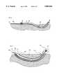
- FIG. 1is a pictorial illustration of an everting bore hole liner according to one embodiment of the present invention.
- FIG. 2is an illustration in cross-section of a system for forming a final bore hole using an everting liner.
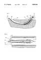
- FIG. 3is a pictorial illustration of the bore hole system shown in FIG. 2 during bore hole formation.
- FIG. 4is a pictorial illustration of the completed bore hole supported by an everted liner.
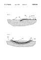
- FIG. 5is a pictorial illustration of an extended everted liner connecting with a hole casing.
- FIG. 6is a pictorial illustration of a bore hole casing that has been pulled through the bore hole by the liner.
- FIG. 7is a pictorial illustration of the liner being inverted from around the inserted bore hole casing.
- FIG. 8is a pictorial illustration of the use of a second liner to facilitate removal of the installation liner from about the casing.
- FIG. 9is a pictorial illustration of another embodiment for using a second liner to facilitate removal of the installation liner from about the casing.
- FIG. 10is a pictorial illustration of a third embodiment for using a second liner to facilitate removal of the installation liner from about the casing.
- FIG. 11depicts the installation of a liner with linear canister storage.
- FIG. 12depicts the use of a first liner to assist in the installation of a second liner.
- FIG. 13depicts the use of a liner to carry instrumentation and the like through the bore hole.
- a suitable flexible bore hole liner system 10is formed from a flexible liner 12 sealed at its distal end 14 and attached to an enclosing reel canister 16 at proximal end 18 of flexible liner 12.
- flexible liner 12is inverted within canister 16 by winding cord-like member 22 onto reel 24.
- Everting liner systemsare well known and are not, per se, the subject of the present invention. Everting liner systems are shown in U.S. Pat. Nos. 5,176,207, issued Jan. 5, 1993; 5,377,754, issued Jan. 3, 1995; and 5,466,093, issued Nov. 14, 1995, all incorporated herein by reference.
- a second cord-like member 26is fixed to distal end 14 of liner 12 and passes about the exterior of liner 12 to proximal end 18 of liner 12. As shown in FIG. 1, the proximal end of cord 26 is fixed to canister 16. Cord 26 can now be pulled to assist in everting liner 12 from a canister to increase the number of applications for using everting liner systems.
- a generally rigid member 32hereinafter called a "pig"
- an attachment point 28which may be a bolt eyelet, pulley, or the like, through which cord 26 passes to assist in everting liner 12.
- eyelet 28pulls cord 26 as cord 26 slides through eyelet 28 and everts liner 12 from canister 16.
- Pig 32is generally a conical/cylindrical shape and further includes a second attachment point 34 for attaching to a drill string component.
- FIGS. 2 and 3further illustrate the installation of flexible liner 12 within a bore hole.
- Pilot hole 38is formed conventionally with entrance end 46 and exit end 40. Pilot hole 38 is typically small (2-5 inches in diameter) and is formed by driving a steerable bit (not shown) through the earth to exit end 40. Drilling fluids are injected through the bit to support the wall of pilot hole 38 and to remove drill cuttings from the hole as the cuttings are generated.
- drill stem 48extends through end 40 and reaming drill bit 42 is attached to the end of drill stem 48.
- pig 32is attached to reamer 42 by connection 34, which is preferably a rotatable connection so that pig 32 does not rotate as rotated to form a bore hole to the desired final diameter.
- Drill stem 48is rotated by drill rig 52 and pulled back through pilot hole 38 as reamer 42 is rotated and drawn through pilot hole 38.
- reamer 42draws pig 32 through enlarged hole 50, which, in turn, pulls cord 26 and everts liner 12 into enlarged bore hole 50.
- Liner 12may be pressurized by a fluid, e.g., water, to maintain the advancing end of liner 12 in contact with pig 32 as reamer 42 reams out pilot hole 38.
- Pressurized everting liner 12supports and seals the wall of bore hole 50 formed by reamer 42.
- the pressure in liner 12is controlled to be greater than the pressure of drilling fluid that is circulating around reamer 42.
- the flow of drilling fluid in pilot hole 38is forced to flow along the pilot hole surrounding drill stem 48 and can be maintained at a relatively high flow rate to remove cuttings generated by reamer 42 through hole entrance 46.
- liner 12inflated within enlarged bore hole 50, the drilling fluid does not flow into the enlarged hole and cannot form a mud cake on the wall of the enlarged final hole.
- the everting, inflated liner 12supports the wall of the enlarged bore hole 50, prevents mud cake formation on the enlarged hole wall 50, reduces the drilling fluid injection into the medium outside enlarged hole 50, improves cutting removal via pilot hole 38 and also prevents cuttings from settling out of the drilling fluid, which would otherwise flow more slowly in the enlarged bore hole.
- FIG. 4illustrates a completed bore hole 50 and liner 12 everted from canister 16 through entrance hole 46.
- the drill string consisting of pig 32, reamer 42, drill pipe 48, and drill rig 52(FIG. 3) is now disconnected from liner 12 and removed for installation of the hole casing and screen.
- liner 12is further everted out of bore hole 50 and extended a distance equal to the length of bore hole 50.
- Exit end 54 of casing string 56is inserted into the distal end of liner 12 and reel 24 (FIG. 1) is rotated to retract cord 22 within canister 16.
- reel 24FIG. 1
- cord 22is retracted, the distal end of flexible liner 12 retracts and the friction between liner 12 and casing 56 clamps casing 56 within pressurized liner 12 whereby inverting liner 12 draws casing 56 within bore hole 50.
- a fluid pipe 58is placed within casing 56 to force water from exit end 54 of casing 56 and between casing 56 and the inverted portion of liner 12, as explained below.
- FIGS. 6 and 7illustrate casing 56 fully drawn through bore hole 50, through exit 40 and encased inside the inverted liner 12 and interior to the portion of pressurized liner 12 that is supporting and contacting the wall of bore hole 50.
- Casing 56is now anchored at the end extending from entrance 46 and exterior to end 62 of liner 12.
- a fluid flowusually water, is then started through fluid pipe 58 and the fluid flows from the end of casing 56 within liner 12 and between casing 56 and the inverted portion of liner 12.
- the fluid pressureforces liner 12 away from casing 56 to reduce the friction therebetween.
- reel 24is rotated to completely invert liner 12 from within bore hole 50 and from around casing 56.
- the fluid within liner 12is conventionally released by a pressure relief valve or the like (not shown) as liner 12 is inverted into canister 16.
- a second flexible lineris preferably used along the interior of the casing to maintain a continuous flow path for the water flow.
- flexible casing liner 76is simply everted within casing 72 and water inlet 78 introduces water within casing liner 76 to hold casing liner 76 against the interior wall of casing 72 to prevent leakage of the water through the well screens and to establish water flow 82 between the outer wall of casing 72 and flexible bore hole liner 74 so that bore hole liner 74 is moved away from the surface of casing 72.
- casing liner 76may be a relatively thin material since it is supported by casing 72 and there is little pressure differential across liner 76.
- casing liner 88includes a water tube 92 within everted liner 88 so that water flow 94 is introduced through the distal end of casing liner 88 and out of casing 84.
- Water tube 92is preferably perforated inside casing liner 88 to pressurize casing liner 88 to seal any casing screens along casing 84.
- a water flow 96is established to force bore hole flexible liner 86 away from the exterior surface of casing 84 as flexible liner 86 is inverted from within bore hole 98.
- FIG. 10depicts a casing liner embodiment that provides the greatest reduction in the force needed to invert flexible bore hole liner 104.
- Casing liner 114is sealed at its distal end 116, which is captured by bore hole flexible liner 104 when casing 102 is captured.
- a double layer of liner 114lies along the surface of casing 102 while a portion of liner 114 seals the interior of casing 102.
- Liner 114is sealed at the entrance to casing 102 with water inlet 108, casing 102 is then lined with liner 114 to force water out of the end of casing 102, but the exiting water is contained within liner 114 to prevent the exiting water from entering the borehole. Injected water 112 still acts to minimize friction between casing 102 and borehole liner 104.
- a long horizontal hose canister 122 shown in FIG. 11may be used in place of the reel, if sufficient space if available.
- Horizontal hose canister 122may be used in a horizontal position, as shown in FIG. 11, or may be used in an inclined position.
- Everting liner 126may be pressurized through fitting 130 so that line 128 is unreeled from reel 132 external to canister 122 to evert liner 126 within bore hole 134. If canister 122 is inclined, liner 126 may evert without the need for pressurization. The overall operation for emplacing a casing in a bore hole is not changed significantly.
- the primary application of the everting liner according to the present inventionis for bore hole casing installation, but the improved everting liner described above with reference to FIG. 1 has a number of applications once liner 12 has been installed within and supports a bore hole wall.
- the casingis replaced with a second everting liner 144 having an external cord 146 for assisting in eversion of the liner.
- the two external cords 146 and 138may be connected by a ring 152 or other suitable slidable attachment so that inversion of first liner 136 assists in eversion of the second liner 144 back through the enlarged bore hole.
- the second linermay include sensors as described in U.S. Pat. No.
- the primary everting linermay be equipped with sensors for monitoring the condition of the bore hole as it is enlarged.
- the lineris formed from a transparent material and a television camera is advanced with the distal end of the everting liner to monitor the liner as it expands against the drilling fluid pressure or to observe the properties of the geologic medium as the bore hole advances.
- logging sonde 158may be connected to the distal end 162 of liner 154, and moved through bore hole 164 as liner 154 is everted. Cable 156 may then serve as the electrical cable for sonde 158 and also as the inverting tether for liner 154. In this manner, bore 164 may be logged at the same time as casing is being installed.
Landscapes
- Engineering & Computer Science (AREA)
- General Engineering & Computer Science (AREA)
- Life Sciences & Earth Sciences (AREA)
- Geology (AREA)
- Mining & Mineral Resources (AREA)
- Mechanical Engineering (AREA)
- Physics & Mathematics (AREA)
- Environmental & Geological Engineering (AREA)
- Fluid Mechanics (AREA)
- General Life Sciences & Earth Sciences (AREA)
- Geochemistry & Mineralogy (AREA)
- Processing Of Stones Or Stones Resemblance Materials (AREA)
Abstract
Description
This invention relates to drilling horizontal bore holes, and, more particularly, to stabilizing horizontal borehole walls.
Many uses arise for horizontal bore holes, particularly in the field of environmental remediation where a geologic structure must be followed for contaminant monitoring and removal. There are several considerations relative to drilling horizontal bore holes. A first consideration is forming the bore hole itself, i.e., drilling the passage through the earth. A second consideration is the support of the bore hole walls. Next, as the hole is drilled, the bore hole cuttings must be removed from the bore hole. The final consideration is the installation of a casing and a well screen within the bore hole.
In conventional drilling, a drilling mud is circulated around a drill bit in order to flush the cuttings from the drill from the hole. The drilling mud is commonly formed of a composition that will form a mud cake on the bore hole wall and support the bore hole walls against collapse. Drilling mud exerts pressure against the hole wall, which then supports the wall. If the drilling mud cannot support the hole wall, the walls will collapse and greatly impede emplacement of the casing and any well screen provided with the casing. The drilling mud may also serve as a lubricant during installation of the casing and well screen, but the casing and screen can experience significant drag forces during installation that can deform and damage the screen.
In drilling horizontal holes for remediation of contaminated geologic formations, however, the drilling mud acts to plug the pore space of the formation. The plugging effect of the drilling mud drastically reduces the permeability of the geologic formation to fluid flow into or out of the hole. The plugging effect is especially pronounced in loosely consolidated sands and gravel that are often the preferred flow paths of contaminates in the geologic structure.
It will also be appreciated that the drilling muds that effectively support the bore hole walls also circulate very slowly in large diameter bore holes. This slow circulation velocity reduces the effectiveness of the drilling mud to remove the drill cuttings from the bore hole.
Accordingly, it is an object of the present invention to provide an alternate means for supporting the wall of a bore hole during horizontal drilling.
It is another object of the present invention to avoid the buildup of mud cake on the bore hole wall and improve the removal of cuttings out of the bore hole.
Yet another object of the present invention is to enable a relatively low viscosity fluid to be circulated during drilling operations to remove cuttings from the bore hole.
One other object of the present invention is to reduce the forces on the hole casing and well screen during emplacement in the bore hole.
Additional objects, advantages and novel features of the invention will be set forth in part in the description which follows, and in part will become apparent to those skilled in the art upon examination of the following or may be learned by practice of the invention. The objects and advantages of the invention may be realized and attained by means of the instrumentalities and combinations particularly pointed out in the appended claims.
To achieve the foregoing and other objects, and in accordance with the purposes of the present invention, as embodied and broadly described herein, the apparatus of this invention may comprise a bore hole support system. A flexible liner defines a generally cylindrical shape with an interior and an exterior when everted and has distal and proximal ends. A canister houses the liner in an inverted condition. A first cord is connected to the distal end of the liner and extends through the interior of the liner to the canister for inverting the liner. A second cord connects to the distal end of the liner and extends along the exterior of the liner to the canister for everting the liner.
In a second aspect of the present invention, there is provided a method for enlarging and supporting a bore hole. An everting liner system is provided at an exit location from a pilot hole. The pilot hole is traversed with a reamer to form the pilot hole diameter to a larger diameter for the final bore hole. The liner system is everted and pressurized behind the reamer as the reamer traverses the pilot hole to support walls defining the bore hole.
In yet another aspect of the present invention, there is provided a method for encasing a horizontal bore hole. An everting liner system is provided at an exit location from a pilot hole. The pilot hole is traversed with a reamer to form the pilot hole diameter to a larger diameter for the final bore hole. The liner system is everted and pressurized behind the reamer as the reamer traverses the pilot hole to support walls defining the bore hole with a flexible liner. The flexible liner is further extended beyond an entrance location from the pilot hole a distance approximating the horizontal bore hole length. A casing is then fixed within the flexible liner, and the flexible liner is inverted back through the bore hole to draw the casing through the bore hole while the casing is enclosed within the flexible liner. The flexible liner is further inverted to remove the flexible liner from about the casing and from within the bore hole.
The accompanying drawings, which are incorporated in and form a part of the specification, illustrate the embodiments of the present invention and, together with the description, serve to explain the principles of the invention. In the drawings:
FIG. 1 is a pictorial illustration of an everting bore hole liner according to one embodiment of the present invention.
FIG. 2 is an illustration in cross-section of a system for forming a final bore hole using an everting liner.
FIG. 3 is a pictorial illustration of the bore hole system shown in FIG. 2 during bore hole formation.
FIG. 4 is a pictorial illustration of the completed bore hole supported by an everted liner.
FIG. 5 is a pictorial illustration of an extended everted liner connecting with a hole casing.
FIG. 6 is a pictorial illustration of a bore hole casing that has been pulled through the bore hole by the liner.
FIG. 7 is a pictorial illustration of the liner being inverted from around the inserted bore hole casing.
FIG. 8 is a pictorial illustration of the use of a second liner to facilitate removal of the installation liner from about the casing.
FIG. 9 is a pictorial illustration of another embodiment for using a second liner to facilitate removal of the installation liner from about the casing.
FIG. 10 is a pictorial illustration of a third embodiment for using a second liner to facilitate removal of the installation liner from about the casing.
FIG. 11 depicts the installation of a liner with linear canister storage.
FIG. 12 depicts the use of a first liner to assist in the installation of a second liner.
FIG. 13 depicts the use of a liner to carry instrumentation and the like through the bore hole.
In accordance with the present invention, the bore hole wall support function of drilling mud is replaced with an everting flexible bore hole liner. As shown in FIG. 1, a suitable flexible borehole liner system 10 is formed from aflexible liner 12 sealed at itsdistal end 14 and attached to an enclosingreel canister 16 atproximal end 18 offlexible liner 12. In an exemplary embodiment,flexible liner 12 is inverted withincanister 16 by winding cord-like member 22 ontoreel 24. Everting liner systems are well known and are not, per se, the subject of the present invention. Everting liner systems are shown in U.S. Pat. Nos. 5,176,207, issued Jan. 5, 1993; 5,377,754, issued Jan. 3, 1995; and 5,466,093, issued Nov. 14, 1995, all incorporated herein by reference.
In accordance with one aspect of the present invention, as shown in FIGS. 1 and 2, a second cord-like member 26 is fixed todistal end 14 ofliner 12 and passes about the exterior ofliner 12 toproximal end 18 ofliner 12. As shown in FIG. 1, the proximal end ofcord 26 is fixed tocanister 16.Cord 26 can now be pulled to assist ineverting liner 12 from a canister to increase the number of applications for using everting liner systems.
In a particular application, described below, a generallyrigid member 32, hereinafter called a "pig", includes anattachment point 28, which may be a bolt eyelet, pulley, or the like, through whichcord 26 passes to assist ineverting liner 12. Aspig 32 is moved through a bore hole, as hereinafter explained,eyelet 28 pullscord 26 ascord 26 slides througheyelet 28 and evertsliner 12 fromcanister 16.Pig 32 is generally a conical/cylindrical shape and further includes asecond attachment point 34 for attaching to a drill string component.
FIGS. 2 and 3 further illustrate the installation offlexible liner 12 within a bore hole.Pilot hole 38 is formed conventionally withentrance end 46 andexit end 40.Pilot hole 38 is typically small (2-5 inches in diameter) and is formed by driving a steerable bit (not shown) through the earth to exitend 40. Drilling fluids are injected through the bit to support the wall ofpilot hole 38 and to remove drill cuttings from the hole as the cuttings are generated.
Whenpilot hole 38 is completed,drill stem 48 extends throughend 40 andreaming drill bit 42 is attached to the end ofdrill stem 48. In accordance with the present invention,pig 32 is attached toreamer 42 byconnection 34, which is preferably a rotatable connection so thatpig 32 does not rotate as rotated to form a bore hole to the desired final diameter.Drill stem 48 is rotated bydrill rig 52 and pulled back throughpilot hole 38 asreamer 42 is rotated and drawn throughpilot hole 38. Thus,reamer 42 drawspig 32 throughenlarged hole 50, which, in turn, pullscord 26 and evertsliner 12 intoenlarged bore hole 50.
The everting, inflatedliner 12 supports the wall of theenlarged bore hole 50, prevents mud cake formation on theenlarged hole wall 50, reduces the drilling fluid injection into the medium outsideenlarged hole 50, improves cutting removal viapilot hole 38 and also prevents cuttings from settling out of the drilling fluid, which would otherwise flow more slowly in the enlarged bore hole.
FIG. 4 illustrates a completedbore hole 50 andliner 12 everted fromcanister 16 throughentrance hole 46. The drill string consisting ofpig 32,reamer 42,drill pipe 48, and drill rig 52 (FIG. 3) is now disconnected fromliner 12 and removed for installation of the hole casing and screen.
As shown in FIG. 5,liner 12 is further everted out ofbore hole 50 and extended a distance equal to the length ofbore hole 50.Exit end 54 ofcasing string 56 is inserted into the distal end ofliner 12 and reel 24 (FIG. 1) is rotated to retractcord 22 withincanister 16. Ascord 22 is retracted, the distal end offlexible liner 12 retracts and the friction betweenliner 12 andcasing 56 clamps casing 56 withinpressurized liner 12 whereby invertingliner 12 draws casing 56 withinbore hole 50. In a preferred embodiment, afluid pipe 58 is placed withincasing 56 to force water fromexit end 54 ofcasing 56 and betweencasing 56 and the inverted portion ofliner 12, as explained below.
FIGS. 6 and 7 illustratecasing 56 fully drawn throughbore hole 50, throughexit 40 and encased inside theinverted liner 12 and interior to the portion ofpressurized liner 12 that is supporting and contacting the wall ofbore hole 50.Casing 56 is now anchored at the end extending fromentrance 46 and exterior to end 62 ofliner 12. A fluid flow, usually water, is then started throughfluid pipe 58 and the fluid flows from the end of casing 56 withinliner 12 and betweencasing 56 and the inverted portion ofliner 12. The fluidpressure forces liner 12 away from casing 56 to reduce the friction therebetween. When the fluid flow is fully established,reel 24 is rotated to completely invertliner 12 from withinbore hole 50 and from around casing 56. It will be understood that the fluid withinliner 12 is conventionally released by a pressure relief valve or the like (not shown) asliner 12 is inverted intocanister 16.
Aspressurized liner 12 is inverted, the wall ofbore hole 50 is no longer supported and the walls may collapse around casing 56 so that casing 56 has been encased withinbore hole 50. Portions ofcasing 56 may include long sections of well screen to enable fluid communication between the interior ofcasing 56 and the geologicstructure enclosing casing 56. The effect of the flexible liner in the installation ofcasing 56, with or without a well screen, is to drastically reduce the friction in installing the well casing against a bore hole wall and to thereby essentially eliminate the usual tensile load of emplacing a casing by pulling it into an unsupported hole. The overall result is to allow the emplacement of screened horizontal wells in unconsolidated media without affecting the flow properties of the surrounding media.
As described above, friction between the flexible liner and the casing is reduced during inverting of the flexible liner by flowing water into the casing so that the water exits between the casing and the liner to force the liner away from the casing. But if the casing includes one or more well screen sections, there will be insufficient pressure differential to move the flexible liner from contact with the casing. In these instances, a second flexible liner is preferably used along the interior of the casing to maintain a continuous flow path for the water flow.
In one embodiment, shown in FIG. 8,flexible casing liner 76 is simply everted withincasing 72 andwater inlet 78 introduces water withincasing liner 76 to holdcasing liner 76 against the interior wall of casing 72 to prevent leakage of the water through the well screens and to establishwater flow 82 between the outer wall ofcasing 72 and flexiblebore hole liner 74 so thatbore hole liner 74 is moved away from the surface ofcasing 72. It will be appreciated thatcasing liner 76 may be a relatively thin material since it is supported by casing 72 and there is little pressure differential acrossliner 76.
A second embodiment is shown in FIG. 9, wherecasing liner 88 includes awater tube 92 within evertedliner 88 so thatwater flow 94 is introduced through the distal end ofcasing liner 88 and out ofcasing 84.Water tube 92 is preferably perforated insidecasing liner 88 to pressurizecasing liner 88 to seal any casing screens alongcasing 84. Awater flow 96 is established to force bore holeflexible liner 86 away from the exterior surface of casing 84 asflexible liner 86 is inverted from withinbore hole 98.
FIG. 10 depicts a casing liner embodiment that provides the greatest reduction in the force needed to invert flexiblebore hole liner 104.Casing liner 114 is sealed at itsdistal end 116, which is captured by bore holeflexible liner 104 when casing 102 is captured. A double layer ofliner 114 lies along the surface ofcasing 102 while a portion ofliner 114 seals the interior ofcasing 102.Liner 114 is sealed at the entrance to casing 102 withwater inlet 108, casing 102 is then lined withliner 114 to force water out of the end ofcasing 102, but the exiting water is contained withinliner 114 to prevent the exiting water from entering the borehole. Injectedwater 112 still acts to minimize friction betweencasing 102 andborehole liner 104.
While the above description is directed to use of a reel-type everting liner, a longhorizontal hose canister 122 shown in FIG. 11 may be used in place of the reel, if sufficient space if available.Horizontal hose canister 122 may be used in a horizontal position, as shown in FIG. 11, or may be used in an inclined position.Everting liner 126 may be pressurized through fitting 130 so thatline 128 is unreeled fromreel 132 external tocanister 122 toevert liner 126 withinbore hole 134. Ifcanister 122 is inclined,liner 126 may evert without the need for pressurization. The overall operation for emplacing a casing in a bore hole is not changed significantly.
The primary application of the everting liner according to the present invention is for bore hole casing installation, but the improved everting liner described above with reference to FIG. 1 has a number of applications onceliner 12 has been installed within and supports a bore hole wall. In one alternate application, shown in FIG. 12, the casing is replaced with asecond everting liner 144 having anexternal cord 146 for assisting in eversion of the liner. The twoexternal cords ring 152 or other suitable slidable attachment so that inversion offirst liner 136 assists in eversion of thesecond liner 144 back through the enlarged bore hole. The second liner may include sensors as described in U.S. Pat. No. 5,176,207 to sample and measure the properties of the formation and entrained contaminants. Likewise, the primary everting liner may be equipped with sensors for monitoring the condition of the bore hole as it is enlarged. In a particular application, the liner is formed from a transparent material and a television camera is advanced with the distal end of the everting liner to monitor the liner as it expands against the drilling fluid pressure or to observe the properties of the geologic medium as the bore hole advances.
In another alternate application shown in FIG. 13,logging sonde 158, of a number of known types, may be connected to thedistal end 162 ofliner 154, and moved throughbore hole 164 asliner 154 is everted.Cable 156 may then serve as the electrical cable forsonde 158 and also as the inverting tether forliner 154. In this manner, bore 164 may be logged at the same time as casing is being installed.
The foregoing description of the preferred embodiments of the invention have been presented for purposes of illustration and description. It is not intended to be exhaustive or to limit the invention to the precise form disclosed, and obviously many modifications and variations are possible in light of the above teaching. The embodiments were chosen and described in order to best explain the principles of the invention and its practical application to thereby enable others skilled in the art to best utilize the invention in various embodiments and with various modifications as are suited to the particular use contemplated. It is intended that the scope of the invention be defined by the claims appended hereto.
Claims (14)
1. A support system for supporting a horizontal bore hole having a known length during installation of a casing comprising:
a flexible liner defining a generally cylindrical shape with an interior and an exterior when everted and having distal and proximal ends, wherein said flexible liner has a length at least twice said length of said bore hole to support said bore hole along a first length when fully everted within said bore hole and a second length to grip and surround said casing as said casing is installed within said bore hole and said first length of said liner;
a canister for housing said liner in an inverted condition;
a first cord connected to said distal end of said liner and extending through said interior of said liner to said canister for inverting said liner; and
a second cord connected to said distal end of said liner and extending along said exterior of said liner to said canister for everting said liner.
2. A bore hole support system according to claim 1, further including a pig slideably attached to said second cord for moving through said bore hole in advance of said flexible liner while everting said flexible liner within said bore hole.
3. A bore hole support system according to claim 2, further including a reamer attached to said pig for enlarging a diameter of a precursor pilot hole for said bore hole to a desired diameter for said bore hole.
4. A method for enlarging and supporting a bore hole having an inlet end and an exit end, comprising the steps of:
forming a pilot hole along a path for said bore hole to define said inlet end and said exit end:
extending a drill string through said pilot hole:
providing an everting liner system at said exit end; traversing said pilot hole from said exit end to said inlet end with a reamer attached to said drill string to form said pilot diameter to a diameter for said bore hole; and
everting and pressurizing said liner system behind said reamer as said reamer traverses said pilot hole from said exit end to said inlet end to support walls defining said bore hole.
5. A method according to claim 4, wherein the step of everting said liner system includes the step of attaching said liner system to said reamer effective to assist said everting of said liner system as said reamer traverses said pilot hole.
6. A method according to claim 5, further including the step of inserting a pig between said reamer and said everting liner system, said pig having a rotatable connection with said reamer and a slidable connection with said flexible liner.
7. A method for encasing a horizontal bore hole, comprising the steps of:
providing an everting liner system at an exit location from a pilot hole;
traversing said pilot hole with a reamer to form said pilot diameter to a diameter for said bore hole;
everting and pressurizing said liner system behind said reamer as said reamer traverses said pilot hole to support walls defining said bore hole with a flexible liner;
extending said flexible liner beyond an entrance location from said pilot hole a distance approximating said horizontal bore hole;
fixing a casing within said flexible liner;
inverting said flexible liner back through said bore hole to draw said casing through said bore hole while said casing is enclosed within said flexible liner; and
continuing to invert said flexible liner to remove said flexible liner from about said casing so that wall of said bore hole collapse about said casing to encase said bore hole walls.
8. A method according to claim 7, further including the step of flowing a fluid between said casing and said flexible liner to reduce friction while removing said flexible liner from about said casing.
9. A method according to claim 8, further including the steps of:
installing within said casing a second flexible liner adapted for placing within said casing; and
placing a fluid within said second flexible liner to seal fluid movement along said casing to said bore hole.
10. A system for emplacing a casing within a borehole having a known length comprising:
a first flexible liner defining a generally cylindrical shape with an interior and an exterior when everted within a bore hole and having distal and proximal ends and a length at least twice said length of said bore hole to support said bore hole along a first length when fully everted within said bore hole and a second length to grip and surround said casing as said casing is installed within said bore hole and said first length of said liner; and
a second flexible liner adapted for placing within said casing and having a fluid inlet for placing a fluid within said casing and between said first flexible liner and said casing.
11. A bore hole casing emplacement system according to claim 10, wherein said second flexible liner is closed and said fluid inlet includes a perforated tube extending within said second flexible liner for introducing a fluid to urge said second liner against said casing and connected for introducing said fluid between said first flexible liner and said casing.
12. A bore hole casing emplacement system according to claim 10, wherein said second flexible liner has a length about three times the length of said casing so that one end of said second flexible liner is captured by said first flexible liner to form a closed volume between said first flexible liner and said casing, wherein fluid injected through said fluid inlet forms a lubricating volume between said first flexible liner and said casing to assist in removing said first flexible liner from about said casing.
13. A bore hole liner emplacement system comprising:
a first flexible liner defining a generally cylindrical shape with an interior and an exterior when everted and having distal and proximal ends and having a first inverting cord connected to said distal end of said first liner and extending through said interior of said first liner for inverting said first liner and a first everting cord connected to said distal end of said first liner and extending along said exterior of said first liner for everting said first liner;
a second flexible liner defining a generally cylindrical shape with an interior and an exterior when everted and having distal and proximal ends and having a second inverting cord connected to said distal end of said second liner and extending through said interior of said second liner for inverting said second liner and a second everting cord connected to said distal end of said second liner and extending along said exterior of said second liner for everting said second liner; and a
connector slidably connecting said first and second everting cords so that said said first flexible liner everts as said second flexible liner inverts and said first flexible liner inverts as said second flexible liner everts.
14. A bore hole liner emplacement system according to claim 13, further including instrument means in said first or second flexible liners for monitoring said borehole as said first or second flexible liner is everted through said bore hole.
Priority Applications (1)
| Application Number | Priority Date | Filing Date | Title |
|---|---|---|---|
| US08/769,656US5803666A (en) | 1996-12-19 | 1996-12-19 | Horizontal drilling method and apparatus |
Applications Claiming Priority (1)
| Application Number | Priority Date | Filing Date | Title |
|---|---|---|---|
| US08/769,656US5803666A (en) | 1996-12-19 | 1996-12-19 | Horizontal drilling method and apparatus |
Publications (1)
| Publication Number | Publication Date |
|---|---|
| US5803666Atrue US5803666A (en) | 1998-09-08 |
Family
ID=25086138
Family Applications (1)
| Application Number | Title | Priority Date | Filing Date |
|---|---|---|---|
| US08/769,656Expired - LifetimeUS5803666A (en) | 1996-12-19 | 1996-12-19 | Horizontal drilling method and apparatus |
Country Status (1)
| Country | Link |
|---|---|
| US (1) | US5803666A (en) |
Cited By (125)
| Publication number | Priority date | Publication date | Assignee | Title |
|---|---|---|---|---|
| US6026900A (en)* | 1998-06-15 | 2000-02-22 | Keller; Carl E. | Multiple liner method for borehole access |
| US6109828A (en)* | 1997-04-17 | 2000-08-29 | Keller; Carl E. | Horizontal drilling method |
| US6244846B1 (en)* | 1998-11-17 | 2001-06-12 | Carl E. Keller | Pressure containment device for everting a flexible liner |
| US6298920B1 (en)* | 1999-02-16 | 2001-10-09 | Carl E. Keller | Method and apparatus for removing a rigid liner from within a cylindrical cavity |
| US6382876B2 (en)* | 2000-07-22 | 2002-05-07 | Korea Advanced Institute Of Science And Technology | Method of repairing or reinforcing worn-out underground burried drainpipes by resin transfer molding process using both flexible tubes and bagging films |
| US20030151297A1 (en)* | 2000-04-05 | 2003-08-14 | Graham Neil Deryck Bray | Apparatus for assembling a liner |
| WO2003078790A1 (en)* | 2002-03-16 | 2003-09-25 | Weatherford/Lamb, Inc. | Lining and drilling a wellbore with an expandable bit |
| US20040149341A1 (en)* | 2001-08-10 | 2004-08-05 | Driver Franklin Thomas | Pressurized bladder canister for installation of cured in place pipe |
| US6857487B2 (en) | 2002-12-30 | 2005-02-22 | Weatherford/Lamb, Inc. | Drilling with concentric strings of casing |
| US6896075B2 (en) | 2002-10-11 | 2005-05-24 | Weatherford/Lamb, Inc. | Apparatus and methods for drilling with casing |
| US6899186B2 (en) | 2002-12-13 | 2005-05-31 | Weatherford/Lamb, Inc. | Apparatus and method of drilling with casing |
| US6953096B2 (en) | 2002-12-31 | 2005-10-11 | Weatherford/Lamb, Inc. | Expandable bit with secondary release device |
| US6994176B2 (en) | 2002-07-29 | 2006-02-07 | Weatherford/Lamb, Inc. | Adjustable rotating guides for spider or elevator |
| US7013997B2 (en) | 1994-10-14 | 2006-03-21 | Weatherford/Lamb, Inc. | Methods and apparatus for cementing drill strings in place for one pass drilling and completion of oil and gas wells |
| US7036610B1 (en) | 1994-10-14 | 2006-05-02 | Weatherford / Lamb, Inc. | Apparatus and method for completing oil and gas wells |
| US7040420B2 (en) | 1994-10-14 | 2006-05-09 | Weatherford/Lamb, Inc. | Methods and apparatus for cementing drill strings in place for one pass drilling and completion of oil and gas wells |
| WO2005003678A3 (en)* | 2003-07-02 | 2006-05-18 | Dyno Nobel Inc | Blast hole liner system and method for the same |
| US7048050B2 (en) | 1994-10-14 | 2006-05-23 | Weatherford/Lamb, Inc. | Method and apparatus for cementing drill strings in place for one pass drilling and completion of oil and gas wells |
| US7073598B2 (en) | 2001-05-17 | 2006-07-11 | Weatherford/Lamb, Inc. | Apparatus and methods for tubular makeup interlock |
| US7090021B2 (en) | 1998-08-24 | 2006-08-15 | Bernd-Georg Pietras | Apparatus for connecting tublars using a top drive |
| US7093675B2 (en) | 2000-08-01 | 2006-08-22 | Weatherford/Lamb, Inc. | Drilling method |
| US7096982B2 (en) | 2003-02-27 | 2006-08-29 | Weatherford/Lamb, Inc. | Drill shoe |
| US7100713B2 (en) | 2000-04-28 | 2006-09-05 | Weatherford/Lamb, Inc. | Expandable apparatus for drift and reaming borehole |
| US7100710B2 (en) | 1994-10-14 | 2006-09-05 | Weatherford/Lamb, Inc. | Methods and apparatus for cementing drill strings in place for one pass drilling and completion of oil and gas wells |
| US7108084B2 (en) | 1994-10-14 | 2006-09-19 | Weatherford/Lamb, Inc. | Methods and apparatus for cementing drill strings in place for one pass drilling and completion of oil and gas wells |
| US7117957B2 (en) | 1998-12-22 | 2006-10-10 | Weatherford/Lamb, Inc. | Methods for drilling and lining a wellbore |
| US7128161B2 (en) | 1998-12-24 | 2006-10-31 | Weatherford/Lamb, Inc. | Apparatus and methods for facilitating the connection of tubulars using a top drive |
| US7128154B2 (en) | 2003-01-30 | 2006-10-31 | Weatherford/Lamb, Inc. | Single-direction cementing plug |
| US7137454B2 (en) | 1998-07-22 | 2006-11-21 | Weatherford/Lamb, Inc. | Apparatus for facilitating the connection of tubulars using a top drive |
| US20060272815A1 (en)* | 2005-06-06 | 2006-12-07 | Baker Hughes Incorporated | Invert emulsion carrier fluid and oil-wetting agent and method of using same |
| US7147068B2 (en) | 1994-10-14 | 2006-12-12 | Weatherford / Lamb, Inc. | Methods and apparatus for cementing drill strings in place for one pass drilling and completion of oil and gas wells |
| US20070017669A1 (en)* | 2003-09-08 | 2007-01-25 | Lurie Paul G | Device and method of lining a wellbore |
| US7188687B2 (en) | 1998-12-22 | 2007-03-13 | Weatherford/Lamb, Inc. | Downhole filter |
| US7191840B2 (en) | 2003-03-05 | 2007-03-20 | Weatherford/Lamb, Inc. | Casing running and drilling system |
| US7213656B2 (en) | 1998-12-24 | 2007-05-08 | Weatherford/Lamb, Inc. | Apparatus and method for facilitating the connection of tubulars using a top drive |
| US7216727B2 (en) | 1999-12-22 | 2007-05-15 | Weatherford/Lamb, Inc. | Drilling bit for drilling while running casing |
| US7219744B2 (en) | 1998-08-24 | 2007-05-22 | Weatherford/Lamb, Inc. | Method and apparatus for connecting tubulars using a top drive |
| US7228901B2 (en) | 1994-10-14 | 2007-06-12 | Weatherford/Lamb, Inc. | Method and apparatus for cementing drill strings in place for one pass drilling and completion of oil and gas wells |
| US7264067B2 (en) | 2003-10-03 | 2007-09-04 | Weatherford/Lamb, Inc. | Method of drilling and completing multiple wellbores inside a single caisson |
| US7284617B2 (en) | 2004-05-20 | 2007-10-23 | Weatherford/Lamb, Inc. | Casing running head |
| US20070260439A1 (en)* | 2006-05-05 | 2007-11-08 | Carl Keller | Flexible borehole liner with diffusion barrier |
| US7303022B2 (en) | 2002-10-11 | 2007-12-04 | Weatherford/Lamb, Inc. | Wired casing |
| US7311148B2 (en) | 1999-02-25 | 2007-12-25 | Weatherford/Lamb, Inc. | Methods and apparatus for wellbore construction and completion |
| US7325610B2 (en) | 2000-04-17 | 2008-02-05 | Weatherford/Lamb, Inc. | Methods and apparatus for handling and drilling with tubulars or casing |
| US7334650B2 (en) | 2000-04-13 | 2008-02-26 | Weatherford/Lamb, Inc. | Apparatus and methods for drilling a wellbore using casing |
| US7360594B2 (en) | 2003-03-05 | 2008-04-22 | Weatherford/Lamb, Inc. | Drilling with casing latch |
| US7370707B2 (en) | 2003-04-04 | 2008-05-13 | Weatherford/Lamb, Inc. | Method and apparatus for handling wellbore tubulars |
| US20080142214A1 (en)* | 2006-12-13 | 2008-06-19 | Carl Keller | Pore fluid sampling system with diffusion barrier |
| US7413020B2 (en) | 2003-03-05 | 2008-08-19 | Weatherford/Lamb, Inc. | Full bore lined wellbores |
| US20090003934A1 (en)* | 2007-06-28 | 2009-01-01 | Carl Keller | Mapping of contaminants in geologic formations |
| US7503397B2 (en) | 2004-07-30 | 2009-03-17 | Weatherford/Lamb, Inc. | Apparatus and methods of setting and retrieving casing with drilling latch and bottom hole assembly |
| US7509722B2 (en) | 1997-09-02 | 2009-03-31 | Weatherford/Lamb, Inc. | Positioning and spinning device |
| US20090095066A1 (en)* | 2007-10-15 | 2009-04-16 | Carl Keller | Vadose zone pore liquid sampling system |
| WO2009065844A1 (en)* | 2007-11-21 | 2009-05-28 | Shell Internationale Research Maatschappij B.V. | Method of drilling a wellbore |
| WO2009074526A1 (en)* | 2007-12-10 | 2009-06-18 | Shell Internationale Research Maatschappij B.V. | System for drilling a wellbore |
| WO2009074573A1 (en)* | 2007-12-11 | 2009-06-18 | Shell Internationale Research Maatschappij B.V. | System for drilling a wellbore |
| US20090178809A1 (en)* | 2005-12-14 | 2009-07-16 | Benjamin Jeffryes | Methods and Apparatus for Well Construction |
| US20090211765A1 (en)* | 2008-02-25 | 2009-08-27 | Keller Carl E | Method for rapid sealing of boreholes |
| US20090255689A1 (en)* | 2006-11-21 | 2009-10-15 | Petrus Cornelis Kriesels | Method of radially expanding a tubular element |
| US7617866B2 (en) | 1998-08-24 | 2009-11-17 | Weatherford/Lamb, Inc. | Methods and apparatus for connecting tubulars using a top drive |
| US7650944B1 (en) | 2003-07-11 | 2010-01-26 | Weatherford/Lamb, Inc. | Vessel for well intervention |
| US7712523B2 (en) | 2000-04-17 | 2010-05-11 | Weatherford/Lamb, Inc. | Top drive casing system |
| US7730965B2 (en) | 2002-12-13 | 2010-06-08 | Weatherford/Lamb, Inc. | Retractable joint and cementing shoe for use in completing a wellbore |
| US20100263859A1 (en)* | 2007-12-13 | 2010-10-21 | Petrus Cornelis Kriesels | Wellbore system |
| US20100270037A1 (en)* | 2007-12-13 | 2010-10-28 | Petrus Cornelis Kriesels | Method of creating a wellbore system |
| US20100284748A1 (en)* | 2006-08-14 | 2010-11-11 | Neil Deryck Bray Graham | Underground mining apparatus |
| US20100319448A1 (en)* | 2009-06-17 | 2010-12-23 | Keller Carl E | Monitoring the water tables in multi-level ground water sampling systems |
| US7857052B2 (en) | 2006-05-12 | 2010-12-28 | Weatherford/Lamb, Inc. | Stage cementing methods used in casing while drilling |
| US7938201B2 (en) | 2002-12-13 | 2011-05-10 | Weatherford/Lamb, Inc. | Deep water drilling with casing |
| USRE42877E1 (en) | 2003-02-07 | 2011-11-01 | Weatherford/Lamb, Inc. | Methods and apparatus for wellbore construction and completion |
| US20110278009A1 (en)* | 2008-01-04 | 2011-11-17 | David Allan Elliott | Method of drilling a wellbore |
| US8276689B2 (en) | 2006-05-22 | 2012-10-02 | Weatherford/Lamb, Inc. | Methods and apparatus for drilling with casing |
| US20130284517A1 (en)* | 2011-01-14 | 2013-10-31 | Petrus Cornelis Kriesels | Method and system for radially expanding a tubular element and directional drilling |
| CN103398217A (en)* | 2013-08-09 | 2013-11-20 | 柳州固瑞机械有限公司 | Horizontal directional driller pulling tube clamp |
| US20130313020A1 (en)* | 2010-12-01 | 2013-11-28 | Bernardus Ludgerus Lubertus Hijlkema | Method and device for drilling a pit or passage, and flexible tube therefor |
| WO2014072381A1 (en)* | 2012-11-09 | 2014-05-15 | Shell Internationale Research Maatschapij B.V. | Method and system for transporting a hydrocarbon fluid |
| US9008971B2 (en) | 2010-12-30 | 2015-04-14 | Carl E. Keller | Measurement of hydraulic head profile in geologic media |
| CN104747197A (en)* | 2015-03-25 | 2015-07-01 | 中铁工程装备集团有限公司 | Earth pressure balance shield tunneling machine earth chamber mud cake detection device |
| US9534477B2 (en) | 2013-03-14 | 2017-01-03 | Carl E. Keller | Method of installation of flexible borehole liner under artesian conditions |
| US9797227B2 (en) | 2013-03-15 | 2017-10-24 | Carl E. Keller | Method for sealing of a borehole liner in an artesian well |
| US10060252B1 (en) | 2013-10-31 | 2018-08-28 | Carl E. Keller | Method for mapping of flow arrivals and other conditions at sealed boreholes |
| US20180320489A1 (en)* | 2015-11-06 | 2018-11-08 | Tyrfing Innovation As | An installation apparatus and method |
| US10139262B2 (en) | 2014-09-04 | 2018-11-27 | Carl E. Keller | Method for air-coupled water level meter system |
| US10337314B2 (en) | 2015-05-28 | 2019-07-02 | Carl E. Keller | Shallow ground water characterization system using flexible borehole liners |
| US10443761B2 (en)* | 2013-12-23 | 2019-10-15 | Herrenknecht Ag | Method and device for trenchless pipe laying |
| CN111206877A (en)* | 2020-03-29 | 2020-05-29 | 张海轩 | A liner pipe feeding device and liner pipe feeding method for pressurized horizontal drilling |
| US10954759B1 (en) | 2018-10-24 | 2021-03-23 | Carl E. Keller | Method for increasing pressure in a flexible liner with a weighted wellhead |
| US11078748B2 (en) | 2019-02-05 | 2021-08-03 | Saudi Arabian Oil Company | Lost circulation shapes |
| US11085262B2 (en) | 2019-01-17 | 2021-08-10 | Carl E. Keller | Method of installation of a flexible borehole liner without eversion |
| US11125075B1 (en) | 2020-03-25 | 2021-09-21 | Saudi Arabian Oil Company | Wellbore fluid level monitoring system |
| US11125046B2 (en) | 2019-12-10 | 2021-09-21 | Saudi Arabian Oil Company | Deploying wellbore patch for mitigating lost circulation |
| US11143001B2 (en) | 2019-06-06 | 2021-10-12 | Carl E. Keller | Optimal screened subsurface well design |
| US11149510B1 (en) | 2020-06-03 | 2021-10-19 | Saudi Arabian Oil Company | Freeing a stuck pipe from a wellbore |
| US11255130B2 (en) | 2020-07-22 | 2022-02-22 | Saudi Arabian Oil Company | Sensing drill bit wear under downhole conditions |
| US11261678B2 (en) | 2019-12-10 | 2022-03-01 | Saudi Arabian Oil Company | Deploying wellbore patch for mitigating lost circulation |
| US11280178B2 (en) | 2020-03-25 | 2022-03-22 | Saudi Arabian Oil Company | Wellbore fluid level monitoring system |
| US11286733B2 (en) | 2020-03-26 | 2022-03-29 | Saudi Arabian Oil Company | Deploying material to limit losses of drilling fluid in a wellbore |
| US11319783B1 (en) | 2019-12-05 | 2022-05-03 | Carl E. Keller | Method for guiding the direction of eversion of a flexible liner |
| US11371324B2 (en)* | 2020-07-16 | 2022-06-28 | Saudi Arabian Oil Company | Method and apparatus for installing infield flexible liner of downhole tubing |
| US11371301B2 (en) | 2019-02-05 | 2022-06-28 | Saudi Arabian Oil Company | Lost circulation shape deployment |
| US11391104B2 (en) | 2020-06-03 | 2022-07-19 | Saudi Arabian Oil Company | Freeing a stuck pipe from a wellbore |
| US11414963B2 (en) | 2020-03-25 | 2022-08-16 | Saudi Arabian Oil Company | Wellbore fluid level monitoring system |
| US11414984B2 (en) | 2020-05-28 | 2022-08-16 | Saudi Arabian Oil Company | Measuring wellbore cross-sections using downhole caliper tools |
| US11414985B2 (en) | 2020-05-28 | 2022-08-16 | Saudi Arabian Oil Company | Measuring wellbore cross-sections using downhole caliper tools |
| US11434707B2 (en) | 2020-06-10 | 2022-09-06 | Saudi Arabian Oil Company | Lost circulation fabric, method, and deployment systems |
| US11434714B2 (en) | 2021-01-04 | 2022-09-06 | Saudi Arabian Oil Company | Adjustable seal for sealing a fluid flow at a wellhead |
| US11434708B2 (en) | 2020-06-10 | 2022-09-06 | Saudi Arabian Oil Company | Lost circulation fabric, method, and deployment systems |
| US11454071B2 (en) | 2020-03-26 | 2022-09-27 | Saudi Arabian Oil Company | Deploying material to limit losses of drilling fluid in a wellbore |
| US11459838B2 (en) | 2020-06-10 | 2022-10-04 | Saudi Arabian Oil Company | Lost circulation fabric, method, and deployment systems |
| US11506044B2 (en) | 2020-07-23 | 2022-11-22 | Saudi Arabian Oil Company | Automatic analysis of drill string dynamics |
| US11572752B2 (en) | 2021-02-24 | 2023-02-07 | Saudi Arabian Oil Company | Downhole cable deployment |
| US11585211B2 (en) | 2019-12-09 | 2023-02-21 | Carl E. Keller | Flexible liner system and method for detecting flowing fractures in media |
| US11624265B1 (en) | 2021-11-12 | 2023-04-11 | Saudi Arabian Oil Company | Cutting pipes in wellbores using downhole autonomous jet cutting tools |
| US11631884B2 (en) | 2020-06-02 | 2023-04-18 | Saudi Arabian Oil Company | Electrolyte structure for a high-temperature, high-pressure lithium battery |
| US11643878B2 (en) | 2020-03-26 | 2023-05-09 | Saudi Arabian Oil Company | Deploying material to limit losses of drilling fluid in a wellbore |
| US11668143B2 (en) | 2019-12-10 | 2023-06-06 | Saudi Arabian Oil Company | Deploying wellbore patch for mitigating lost circulation |
| US11697991B2 (en) | 2021-01-13 | 2023-07-11 | Saudi Arabian Oil Company | Rig sensor testing and calibration |
| US11709118B2 (en) | 2020-02-13 | 2023-07-25 | Saudi Arabian Oil Company | Lost circulation materials (LCM) and lost circulation shapes (LCS) test fixture |
| US11719089B2 (en) | 2020-07-15 | 2023-08-08 | Saudi Arabian Oil Company | Analysis of drilling slurry solids by image processing |
| US11727555B2 (en) | 2021-02-25 | 2023-08-15 | Saudi Arabian Oil Company | Rig power system efficiency optimization through image processing |
| US11846151B2 (en) | 2021-03-09 | 2023-12-19 | Saudi Arabian Oil Company | Repairing a cased wellbore |
| US11867008B2 (en) | 2020-11-05 | 2024-01-09 | Saudi Arabian Oil Company | System and methods for the measurement of drilling mud flow in real-time |
| US11867012B2 (en) | 2021-12-06 | 2024-01-09 | Saudi Arabian Oil Company | Gauge cutter and sampler apparatus |
| US11980921B1 (en) | 2021-03-04 | 2024-05-14 | Carl E. Keller | Method for removing NAPL contaminants from geologic formations |
| US12203366B2 (en) | 2023-05-02 | 2025-01-21 | Saudi Arabian Oil Company | Collecting samples from wellbores |
Citations (13)
| Publication number | Priority date | Publication date | Assignee | Title |
|---|---|---|---|---|
| US2927775A (en)* | 1957-12-10 | 1960-03-08 | Jersey Prod Res Co | Unconsolidated formation core barrel |
| US3168924A (en)* | 1963-05-10 | 1965-02-09 | Louis W Anderson | Plastic well screen point |
| US3927164A (en)* | 1972-07-25 | 1975-12-16 | Seiki Shimabukuro | Method for turning a flexible tube inside out |
| US4064211A (en)* | 1972-12-08 | 1977-12-20 | Insituform (Pipes & Structures) Ltd. | Lining of passageways |
| US4522125A (en)* | 1983-06-09 | 1985-06-11 | C-I-L Inc. | Charging large diameter vertical boreholes |
| US4680066A (en)* | 1984-07-13 | 1987-07-14 | Insituform Group Limited | Lining of pipelines or passageways |
| US4770562A (en)* | 1986-10-16 | 1988-09-13 | Hans Muller | Method of salvaging a pipe conduit buried under ground |
| US4785885A (en)* | 1987-05-13 | 1988-11-22 | Cherrington Martin D | Method and apparatus for cementing a production conduit within an underground arcuate bore |
| US5169264A (en)* | 1990-04-05 | 1992-12-08 | Kidoh Technical Ins. Co., Ltd. | Propulsion process of buried pipe |
| US5176207A (en)* | 1989-08-30 | 1993-01-05 | Science & Engineering, Inc. | Underground instrumentation emplacement system |
| US5375668A (en)* | 1990-04-12 | 1994-12-27 | H T C A/S | Borehole, as well as a method and an apparatus for forming it |
| US5377754A (en)* | 1994-03-02 | 1995-01-03 | Keller; Carl E. | Progressive fluid sampling for boreholes |
| US5466093A (en)* | 1994-05-16 | 1995-11-14 | Keller; Carl E. | Method and apparatus for removing contaminants from a duct or pipe |
- 1996
- 1996-12-19USUS08/769,656patent/US5803666A/ennot_activeExpired - Lifetime
Patent Citations (13)
| Publication number | Priority date | Publication date | Assignee | Title |
|---|---|---|---|---|
| US2927775A (en)* | 1957-12-10 | 1960-03-08 | Jersey Prod Res Co | Unconsolidated formation core barrel |
| US3168924A (en)* | 1963-05-10 | 1965-02-09 | Louis W Anderson | Plastic well screen point |
| US3927164A (en)* | 1972-07-25 | 1975-12-16 | Seiki Shimabukuro | Method for turning a flexible tube inside out |
| US4064211A (en)* | 1972-12-08 | 1977-12-20 | Insituform (Pipes & Structures) Ltd. | Lining of passageways |
| US4522125A (en)* | 1983-06-09 | 1985-06-11 | C-I-L Inc. | Charging large diameter vertical boreholes |
| US4680066A (en)* | 1984-07-13 | 1987-07-14 | Insituform Group Limited | Lining of pipelines or passageways |
| US4770562A (en)* | 1986-10-16 | 1988-09-13 | Hans Muller | Method of salvaging a pipe conduit buried under ground |
| US4785885A (en)* | 1987-05-13 | 1988-11-22 | Cherrington Martin D | Method and apparatus for cementing a production conduit within an underground arcuate bore |
| US5176207A (en)* | 1989-08-30 | 1993-01-05 | Science & Engineering, Inc. | Underground instrumentation emplacement system |
| US5169264A (en)* | 1990-04-05 | 1992-12-08 | Kidoh Technical Ins. Co., Ltd. | Propulsion process of buried pipe |
| US5375668A (en)* | 1990-04-12 | 1994-12-27 | H T C A/S | Borehole, as well as a method and an apparatus for forming it |
| US5377754A (en)* | 1994-03-02 | 1995-01-03 | Keller; Carl E. | Progressive fluid sampling for boreholes |
| US5466093A (en)* | 1994-05-16 | 1995-11-14 | Keller; Carl E. | Method and apparatus for removing contaminants from a duct or pipe |
Cited By (174)
| Publication number | Priority date | Publication date | Assignee | Title |
|---|---|---|---|---|
| US7165634B2 (en) | 1994-10-14 | 2007-01-23 | Weatherford/Lamb, Inc. | Method and apparatus for cementing drill strings in place for one pass drilling and completion of oil and gas wells |
| US7048050B2 (en) | 1994-10-14 | 2006-05-23 | Weatherford/Lamb, Inc. | Method and apparatus for cementing drill strings in place for one pass drilling and completion of oil and gas wells |
| US7100710B2 (en) | 1994-10-14 | 2006-09-05 | Weatherford/Lamb, Inc. | Methods and apparatus for cementing drill strings in place for one pass drilling and completion of oil and gas wells |
| US7040420B2 (en) | 1994-10-14 | 2006-05-09 | Weatherford/Lamb, Inc. | Methods and apparatus for cementing drill strings in place for one pass drilling and completion of oil and gas wells |
| US7036610B1 (en) | 1994-10-14 | 2006-05-02 | Weatherford / Lamb, Inc. | Apparatus and method for completing oil and gas wells |
| US7013997B2 (en) | 1994-10-14 | 2006-03-21 | Weatherford/Lamb, Inc. | Methods and apparatus for cementing drill strings in place for one pass drilling and completion of oil and gas wells |
| US7108084B2 (en) | 1994-10-14 | 2006-09-19 | Weatherford/Lamb, Inc. | Methods and apparatus for cementing drill strings in place for one pass drilling and completion of oil and gas wells |
| US7234542B2 (en) | 1994-10-14 | 2007-06-26 | Weatherford/Lamb, Inc. | Methods and apparatus for cementing drill strings in place for one pass drilling and completion of oil and gas wells |
| US7228901B2 (en) | 1994-10-14 | 2007-06-12 | Weatherford/Lamb, Inc. | Method and apparatus for cementing drill strings in place for one pass drilling and completion of oil and gas wells |
| US7147068B2 (en) | 1994-10-14 | 2006-12-12 | Weatherford / Lamb, Inc. | Methods and apparatus for cementing drill strings in place for one pass drilling and completion of oil and gas wells |
| US6109828A (en)* | 1997-04-17 | 2000-08-29 | Keller; Carl E. | Horizontal drilling method |
| US7509722B2 (en) | 1997-09-02 | 2009-03-31 | Weatherford/Lamb, Inc. | Positioning and spinning device |
| US6026900A (en)* | 1998-06-15 | 2000-02-22 | Keller; Carl E. | Multiple liner method for borehole access |
| US7137454B2 (en) | 1998-07-22 | 2006-11-21 | Weatherford/Lamb, Inc. | Apparatus for facilitating the connection of tubulars using a top drive |
| US7219744B2 (en) | 1998-08-24 | 2007-05-22 | Weatherford/Lamb, Inc. | Method and apparatus for connecting tubulars using a top drive |
| US7090021B2 (en) | 1998-08-24 | 2006-08-15 | Bernd-Georg Pietras | Apparatus for connecting tublars using a top drive |
| US7617866B2 (en) | 1998-08-24 | 2009-11-17 | Weatherford/Lamb, Inc. | Methods and apparatus for connecting tubulars using a top drive |
| US6244846B1 (en)* | 1998-11-17 | 2001-06-12 | Carl E. Keller | Pressure containment device for everting a flexible liner |
| US7188687B2 (en) | 1998-12-22 | 2007-03-13 | Weatherford/Lamb, Inc. | Downhole filter |
| US7117957B2 (en) | 1998-12-22 | 2006-10-10 | Weatherford/Lamb, Inc. | Methods for drilling and lining a wellbore |
| US7213656B2 (en) | 1998-12-24 | 2007-05-08 | Weatherford/Lamb, Inc. | Apparatus and method for facilitating the connection of tubulars using a top drive |
| US7128161B2 (en) | 1998-12-24 | 2006-10-31 | Weatherford/Lamb, Inc. | Apparatus and methods for facilitating the connection of tubulars using a top drive |
| US6298920B1 (en)* | 1999-02-16 | 2001-10-09 | Carl E. Keller | Method and apparatus for removing a rigid liner from within a cylindrical cavity |
| US7311148B2 (en) | 1999-02-25 | 2007-12-25 | Weatherford/Lamb, Inc. | Methods and apparatus for wellbore construction and completion |
| US7216727B2 (en) | 1999-12-22 | 2007-05-15 | Weatherford/Lamb, Inc. | Drilling bit for drilling while running casing |
| US20080315665A1 (en)* | 2000-04-05 | 2008-12-25 | Sord Resources Limited | Apparatus for assembling a liner |
| US20050179307A1 (en)* | 2000-04-05 | 2005-08-18 | Graham Neil D.B. | Apparatus for assembling a liner |
| US6953307B2 (en)* | 2000-04-05 | 2005-10-11 | Sord Technologies Limited | Apparatus for assembling a liner |
| US20030151297A1 (en)* | 2000-04-05 | 2003-08-14 | Graham Neil Deryck Bray | Apparatus for assembling a liner |
| US7318627B2 (en) | 2000-04-05 | 2008-01-15 | Sord Technologies Limted | Recovery head with track seal |
| US20070236075A1 (en)* | 2000-04-05 | 2007-10-11 | Sord Technologies Limited | Apparatus for assembling a liner |
| US7410220B2 (en) | 2000-04-05 | 2008-08-12 | Sord Resources Limited | Apparatus for assembling a liner |
| US7334650B2 (en) | 2000-04-13 | 2008-02-26 | Weatherford/Lamb, Inc. | Apparatus and methods for drilling a wellbore using casing |
| US7325610B2 (en) | 2000-04-17 | 2008-02-05 | Weatherford/Lamb, Inc. | Methods and apparatus for handling and drilling with tubulars or casing |
| US7712523B2 (en) | 2000-04-17 | 2010-05-11 | Weatherford/Lamb, Inc. | Top drive casing system |
| US7100713B2 (en) | 2000-04-28 | 2006-09-05 | Weatherford/Lamb, Inc. | Expandable apparatus for drift and reaming borehole |
| US6382876B2 (en)* | 2000-07-22 | 2002-05-07 | Korea Advanced Institute Of Science And Technology | Method of repairing or reinforcing worn-out underground burried drainpipes by resin transfer molding process using both flexible tubes and bagging films |
| US7093675B2 (en) | 2000-08-01 | 2006-08-22 | Weatherford/Lamb, Inc. | Drilling method |
| US7073598B2 (en) | 2001-05-17 | 2006-07-11 | Weatherford/Lamb, Inc. | Apparatus and methods for tubular makeup interlock |
| US6969216B2 (en)* | 2001-08-10 | 2005-11-29 | Insituform (Netherlands) B.V. | Pressurized bladder canister for installation of cured in place pipe |
| US20040149341A1 (en)* | 2001-08-10 | 2004-08-05 | Driver Franklin Thomas | Pressurized bladder canister for installation of cured in place pipe |
| US7004264B2 (en) | 2002-03-16 | 2006-02-28 | Weatherford/Lamb, Inc. | Bore lining and drilling |
| GB2393989B (en)* | 2002-03-16 | 2005-12-07 | Weatherford Lamb | Lining and drilling a wellbore with an expandable bit |
| WO2003078790A1 (en)* | 2002-03-16 | 2003-09-25 | Weatherford/Lamb, Inc. | Lining and drilling a wellbore with an expandable bit |
| GB2393989A (en)* | 2002-03-16 | 2004-04-14 | Weatherford Lamb | Lining and drilling a wellbore with an expandable bit |
| US6994176B2 (en) | 2002-07-29 | 2006-02-07 | Weatherford/Lamb, Inc. | Adjustable rotating guides for spider or elevator |
| US7303022B2 (en) | 2002-10-11 | 2007-12-04 | Weatherford/Lamb, Inc. | Wired casing |
| US6896075B2 (en) | 2002-10-11 | 2005-05-24 | Weatherford/Lamb, Inc. | Apparatus and methods for drilling with casing |
| US7090023B2 (en) | 2002-10-11 | 2006-08-15 | Weatherford/Lamb, Inc. | Apparatus and methods for drilling with casing |
| US7938201B2 (en) | 2002-12-13 | 2011-05-10 | Weatherford/Lamb, Inc. | Deep water drilling with casing |
| US7730965B2 (en) | 2002-12-13 | 2010-06-08 | Weatherford/Lamb, Inc. | Retractable joint and cementing shoe for use in completing a wellbore |
| US7083005B2 (en) | 2002-12-13 | 2006-08-01 | Weatherford/Lamb, Inc. | Apparatus and method of drilling with casing |
| US6899186B2 (en) | 2002-12-13 | 2005-05-31 | Weatherford/Lamb, Inc. | Apparatus and method of drilling with casing |
| US6857487B2 (en) | 2002-12-30 | 2005-02-22 | Weatherford/Lamb, Inc. | Drilling with concentric strings of casing |
| US7131505B2 (en) | 2002-12-30 | 2006-11-07 | Weatherford/Lamb, Inc. | Drilling with concentric strings of casing |
| US6953096B2 (en) | 2002-12-31 | 2005-10-11 | Weatherford/Lamb, Inc. | Expandable bit with secondary release device |
| US7128154B2 (en) | 2003-01-30 | 2006-10-31 | Weatherford/Lamb, Inc. | Single-direction cementing plug |
| USRE42877E1 (en) | 2003-02-07 | 2011-11-01 | Weatherford/Lamb, Inc. | Methods and apparatus for wellbore construction and completion |
| US7096982B2 (en) | 2003-02-27 | 2006-08-29 | Weatherford/Lamb, Inc. | Drill shoe |
| US7413020B2 (en) | 2003-03-05 | 2008-08-19 | Weatherford/Lamb, Inc. | Full bore lined wellbores |
| US7360594B2 (en) | 2003-03-05 | 2008-04-22 | Weatherford/Lamb, Inc. | Drilling with casing latch |
| US7191840B2 (en) | 2003-03-05 | 2007-03-20 | Weatherford/Lamb, Inc. | Casing running and drilling system |
| US7370707B2 (en) | 2003-04-04 | 2008-05-13 | Weatherford/Lamb, Inc. | Method and apparatus for handling wellbore tubulars |
| WO2005003678A3 (en)* | 2003-07-02 | 2006-05-18 | Dyno Nobel Inc | Blast hole liner system and method for the same |
| US7650944B1 (en) | 2003-07-11 | 2010-01-26 | Weatherford/Lamb, Inc. | Vessel for well intervention |
| US20070017669A1 (en)* | 2003-09-08 | 2007-01-25 | Lurie Paul G | Device and method of lining a wellbore |
| US7387174B2 (en)* | 2003-09-08 | 2008-06-17 | Bp Exploration Operating Company Limited | Device and method of lining a wellbore |
| US7264067B2 (en) | 2003-10-03 | 2007-09-04 | Weatherford/Lamb, Inc. | Method of drilling and completing multiple wellbores inside a single caisson |
| US7284617B2 (en) | 2004-05-20 | 2007-10-23 | Weatherford/Lamb, Inc. | Casing running head |
| US7503397B2 (en) | 2004-07-30 | 2009-03-17 | Weatherford/Lamb, Inc. | Apparatus and methods of setting and retrieving casing with drilling latch and bottom hole assembly |
| US7803743B2 (en) | 2005-06-06 | 2010-09-28 | Baker Hughes Incorporated | Invert emulsion carrier fluid and oil-wetting agent and method of using same |
| US20060272815A1 (en)* | 2005-06-06 | 2006-12-07 | Baker Hughes Incorporated | Invert emulsion carrier fluid and oil-wetting agent and method of using same |
| US20090178809A1 (en)* | 2005-12-14 | 2009-07-16 | Benjamin Jeffryes | Methods and Apparatus for Well Construction |
| US7946359B2 (en)* | 2005-12-14 | 2011-05-24 | Schlumberger Technology Corporation | Methods and apparatus for well construction |
| US7841405B2 (en) | 2006-05-05 | 2010-11-30 | Carl Keller | Flexible borehole liner with diffusion barrier and method of use thereof |
| US20070260439A1 (en)* | 2006-05-05 | 2007-11-08 | Carl Keller | Flexible borehole liner with diffusion barrier |
| US7857052B2 (en) | 2006-05-12 | 2010-12-28 | Weatherford/Lamb, Inc. | Stage cementing methods used in casing while drilling |
| US8276689B2 (en) | 2006-05-22 | 2012-10-02 | Weatherford/Lamb, Inc. | Methods and apparatus for drilling with casing |
| US8920074B2 (en)* | 2006-08-14 | 2014-12-30 | Z-Filter Pty Ltd. | Underground mining apparatus |
| US20100284748A1 (en)* | 2006-08-14 | 2010-11-11 | Neil Deryck Bray Graham | Underground mining apparatus |
| US20090255689A1 (en)* | 2006-11-21 | 2009-10-15 | Petrus Cornelis Kriesels | Method of radially expanding a tubular element |
| US8141647B2 (en)* | 2006-11-21 | 2012-03-27 | Shell Oil Company | Method of radially expanding a tubular element |
| US7753120B2 (en) | 2006-12-13 | 2010-07-13 | Carl Keller | Pore fluid sampling system with diffusion barrier and method of use thereof |
| US20080142214A1 (en)* | 2006-12-13 | 2008-06-19 | Carl Keller | Pore fluid sampling system with diffusion barrier |
| US20090003934A1 (en)* | 2007-06-28 | 2009-01-01 | Carl Keller | Mapping of contaminants in geologic formations |
| US7896578B2 (en) | 2007-06-28 | 2011-03-01 | Carl Keller | Mapping of contaminants in geologic formations |
| US20090095066A1 (en)* | 2007-10-15 | 2009-04-16 | Carl Keller | Vadose zone pore liquid sampling system |
| US8069715B2 (en) | 2007-10-15 | 2011-12-06 | Carl Keller | Vadose zone pore liquid sampling system |
| US20100276202A1 (en)* | 2007-11-21 | 2010-11-04 | Petrus Cornelis Kriesels | Method of drilling a wellbore |
| WO2009065844A1 (en)* | 2007-11-21 | 2009-05-28 | Shell Internationale Research Maatschappij B.V. | Method of drilling a wellbore |
| US8196669B2 (en) | 2007-11-21 | 2012-06-12 | Shell Oil Company | Method of drilling a wellbore |
| CN101868593B (en)* | 2007-11-21 | 2013-10-30 | 国际壳牌研究有限公司 | Method of drilling wellbore |
| GB2468416B (en)* | 2007-11-21 | 2012-02-01 | Shell Int Research | Method of drilling a wellbore |
| AU2008327919B2 (en)* | 2007-11-21 | 2011-08-18 | Shell Internationale Research Maatschappij B.V. | Method of drilling a wellbore |
| GB2468416A (en)* | 2007-11-21 | 2010-09-08 | Shell Int Research | Method of drilling a wellbore |
| GB2467866B (en)* | 2007-12-10 | 2012-03-07 | Shell Int Research | System for drilling a wellbore |
| AU2008334744B2 (en)* | 2007-12-10 | 2011-09-08 | Shell Internationale Research Maatschappij B.V. | System for drilling a wellbore |
| GB2467866A (en)* | 2007-12-10 | 2010-08-18 | Shell Int Research | System for drilling a wellbore |
| WO2009074526A1 (en)* | 2007-12-10 | 2009-06-18 | Shell Internationale Research Maatschappij B.V. | System for drilling a wellbore |
| US20100252333A1 (en)* | 2007-12-10 | 2010-10-07 | Blange Jan-Jette | System for drilling a wellbore |
| US20100294487A1 (en)* | 2007-12-11 | 2010-11-25 | Petrus Cornelis Kriesels | System for drilling a wellbore |
| WO2009074573A1 (en)* | 2007-12-11 | 2009-06-18 | Shell Internationale Research Maatschappij B.V. | System for drilling a wellbore |
| US8479843B2 (en) | 2007-12-11 | 2013-07-09 | Shell Oil Company | System for drilling a wellbore |
| US20100263859A1 (en)* | 2007-12-13 | 2010-10-21 | Petrus Cornelis Kriesels | Wellbore system |
| US20100270037A1 (en)* | 2007-12-13 | 2010-10-28 | Petrus Cornelis Kriesels | Method of creating a wellbore system |
| US8316932B2 (en)* | 2007-12-13 | 2012-11-27 | Shell Oil Company | Wellbore system |
| US8555987B2 (en) | 2007-12-13 | 2013-10-15 | Shell Oil Company | Method of creating a wellbore system |
| US20110278009A1 (en)* | 2008-01-04 | 2011-11-17 | David Allan Elliott | Method of drilling a wellbore |
| US8281879B2 (en)* | 2008-01-04 | 2012-10-09 | Shell Oil Company | Method of drilling a wellbore |
| US20090211765A1 (en)* | 2008-02-25 | 2009-08-27 | Keller Carl E | Method for rapid sealing of boreholes |
| US8176977B2 (en) | 2008-02-25 | 2012-05-15 | Keller Carl E | Method for rapid sealing of boreholes |
| US8424377B2 (en) | 2009-06-17 | 2013-04-23 | Carl E. Keller | Monitoring the water tables in multi-level ground water sampling systems |
| US20100319448A1 (en)* | 2009-06-17 | 2010-12-23 | Keller Carl E | Monitoring the water tables in multi-level ground water sampling systems |
| US20130313020A1 (en)* | 2010-12-01 | 2013-11-28 | Bernardus Ludgerus Lubertus Hijlkema | Method and device for drilling a pit or passage, and flexible tube therefor |
| US9008971B2 (en) | 2010-12-30 | 2015-04-14 | Carl E. Keller | Measurement of hydraulic head profile in geologic media |
| US20130284517A1 (en)* | 2011-01-14 | 2013-10-31 | Petrus Cornelis Kriesels | Method and system for radially expanding a tubular element and directional drilling |
| US9464481B2 (en)* | 2011-01-14 | 2016-10-11 | Shell Oil Company | Method and system for radially expanding a tubular element and directional drilling |
| WO2014072381A1 (en)* | 2012-11-09 | 2014-05-15 | Shell Internationale Research Maatschapij B.V. | Method and system for transporting a hydrocarbon fluid |
| US9534477B2 (en) | 2013-03-14 | 2017-01-03 | Carl E. Keller | Method of installation of flexible borehole liner under artesian conditions |
| US9797227B2 (en) | 2013-03-15 | 2017-10-24 | Carl E. Keller | Method for sealing of a borehole liner in an artesian well |
| CN103398217A (en)* | 2013-08-09 | 2013-11-20 | 柳州固瑞机械有限公司 | Horizontal directional driller pulling tube clamp |
| CN103398217B (en)* | 2013-08-09 | 2015-03-18 | 柳州固瑞机械有限公司 | Horizontal directional driller pulling tube clamp |
| US10060252B1 (en) | 2013-10-31 | 2018-08-28 | Carl E. Keller | Method for mapping of flow arrivals and other conditions at sealed boreholes |
| US10443761B2 (en)* | 2013-12-23 | 2019-10-15 | Herrenknecht Ag | Method and device for trenchless pipe laying |
| US10139262B2 (en) | 2014-09-04 | 2018-11-27 | Carl E. Keller | Method for air-coupled water level meter system |
| CN104747197B (en)* | 2015-03-25 | 2016-09-14 | 中铁工程装备集团有限公司 | A kind of balancing earth-pressure shielding machine soil storehouse mud cake detection device |
| CN104747197A (en)* | 2015-03-25 | 2015-07-01 | 中铁工程装备集团有限公司 | Earth pressure balance shield tunneling machine earth chamber mud cake detection device |
| US10337314B2 (en) | 2015-05-28 | 2019-07-02 | Carl E. Keller | Shallow ground water characterization system using flexible borehole liners |
| US20180320489A1 (en)* | 2015-11-06 | 2018-11-08 | Tyrfing Innovation As | An installation apparatus and method |
| US10837263B2 (en)* | 2015-11-06 | 2020-11-17 | Tyrfing Innovation As | Installation apparatus and method |
| US10954759B1 (en) | 2018-10-24 | 2021-03-23 | Carl E. Keller | Method for increasing pressure in a flexible liner with a weighted wellhead |
| US11085262B2 (en) | 2019-01-17 | 2021-08-10 | Carl E. Keller | Method of installation of a flexible borehole liner without eversion |
| US11078748B2 (en) | 2019-02-05 | 2021-08-03 | Saudi Arabian Oil Company | Lost circulation shapes |
| US11371301B2 (en) | 2019-02-05 | 2022-06-28 | Saudi Arabian Oil Company | Lost circulation shape deployment |
| US11473396B2 (en) | 2019-02-05 | 2022-10-18 | Saudi Arabian Oil Company | Lost circulation shapes |
| US11143001B2 (en) | 2019-06-06 | 2021-10-12 | Carl E. Keller | Optimal screened subsurface well design |
| US11319783B1 (en) | 2019-12-05 | 2022-05-03 | Carl E. Keller | Method for guiding the direction of eversion of a flexible liner |
| US11585211B2 (en) | 2019-12-09 | 2023-02-21 | Carl E. Keller | Flexible liner system and method for detecting flowing fractures in media |
| US11125046B2 (en) | 2019-12-10 | 2021-09-21 | Saudi Arabian Oil Company | Deploying wellbore patch for mitigating lost circulation |
| US11668143B2 (en) | 2019-12-10 | 2023-06-06 | Saudi Arabian Oil Company | Deploying wellbore patch for mitigating lost circulation |
| US11261678B2 (en) | 2019-12-10 | 2022-03-01 | Saudi Arabian Oil Company | Deploying wellbore patch for mitigating lost circulation |
| US11709118B2 (en) | 2020-02-13 | 2023-07-25 | Saudi Arabian Oil Company | Lost circulation materials (LCM) and lost circulation shapes (LCS) test fixture |
| US11125075B1 (en) | 2020-03-25 | 2021-09-21 | Saudi Arabian Oil Company | Wellbore fluid level monitoring system |
| US11280178B2 (en) | 2020-03-25 | 2022-03-22 | Saudi Arabian Oil Company | Wellbore fluid level monitoring system |
| US11414963B2 (en) | 2020-03-25 | 2022-08-16 | Saudi Arabian Oil Company | Wellbore fluid level monitoring system |
| US11643878B2 (en) | 2020-03-26 | 2023-05-09 | Saudi Arabian Oil Company | Deploying material to limit losses of drilling fluid in a wellbore |
| US11454071B2 (en) | 2020-03-26 | 2022-09-27 | Saudi Arabian Oil Company | Deploying material to limit losses of drilling fluid in a wellbore |
| US11286733B2 (en) | 2020-03-26 | 2022-03-29 | Saudi Arabian Oil Company | Deploying material to limit losses of drilling fluid in a wellbore |
| CN111206877A (en)* | 2020-03-29 | 2020-05-29 | 张海轩 | A liner pipe feeding device and liner pipe feeding method for pressurized horizontal drilling |
| US11414984B2 (en) | 2020-05-28 | 2022-08-16 | Saudi Arabian Oil Company | Measuring wellbore cross-sections using downhole caliper tools |
| US11414985B2 (en) | 2020-05-28 | 2022-08-16 | Saudi Arabian Oil Company | Measuring wellbore cross-sections using downhole caliper tools |
| US11631884B2 (en) | 2020-06-02 | 2023-04-18 | Saudi Arabian Oil Company | Electrolyte structure for a high-temperature, high-pressure lithium battery |
| US12166168B2 (en) | 2020-06-02 | 2024-12-10 | Saudi Arabian Oil Company | Electrolyte structure for a high-temperature, high-pressure lithium battery |
| US11719063B2 (en) | 2020-06-03 | 2023-08-08 | Saudi Arabian Oil Company | Freeing a stuck pipe from a wellbore |
| US11149510B1 (en) | 2020-06-03 | 2021-10-19 | Saudi Arabian Oil Company | Freeing a stuck pipe from a wellbore |
| US11421497B2 (en) | 2020-06-03 | 2022-08-23 | Saudi Arabian Oil Company | Freeing a stuck pipe from a wellbore |
| US11391104B2 (en) | 2020-06-03 | 2022-07-19 | Saudi Arabian Oil Company | Freeing a stuck pipe from a wellbore |
| US11434707B2 (en) | 2020-06-10 | 2022-09-06 | Saudi Arabian Oil Company | Lost circulation fabric, method, and deployment systems |
| US11434708B2 (en) | 2020-06-10 | 2022-09-06 | Saudi Arabian Oil Company | Lost circulation fabric, method, and deployment systems |
| US11459838B2 (en) | 2020-06-10 | 2022-10-04 | Saudi Arabian Oil Company | Lost circulation fabric, method, and deployment systems |
| US11719089B2 (en) | 2020-07-15 | 2023-08-08 | Saudi Arabian Oil Company | Analysis of drilling slurry solids by image processing |
| US11371324B2 (en)* | 2020-07-16 | 2022-06-28 | Saudi Arabian Oil Company | Method and apparatus for installing infield flexible liner of downhole tubing |
| US11255130B2 (en) | 2020-07-22 | 2022-02-22 | Saudi Arabian Oil Company | Sensing drill bit wear under downhole conditions |
| US11506044B2 (en) | 2020-07-23 | 2022-11-22 | Saudi Arabian Oil Company | Automatic analysis of drill string dynamics |
| US11867008B2 (en) | 2020-11-05 | 2024-01-09 | Saudi Arabian Oil Company | System and methods for the measurement of drilling mud flow in real-time |
| US11434714B2 (en) | 2021-01-04 | 2022-09-06 | Saudi Arabian Oil Company | Adjustable seal for sealing a fluid flow at a wellhead |
| US11697991B2 (en) | 2021-01-13 | 2023-07-11 | Saudi Arabian Oil Company | Rig sensor testing and calibration |
| US11572752B2 (en) | 2021-02-24 | 2023-02-07 | Saudi Arabian Oil Company | Downhole cable deployment |
| US11727555B2 (en) | 2021-02-25 | 2023-08-15 | Saudi Arabian Oil Company | Rig power system efficiency optimization through image processing |
| US11980921B1 (en) | 2021-03-04 | 2024-05-14 | Carl E. Keller | Method for removing NAPL contaminants from geologic formations |
| US11846151B2 (en) | 2021-03-09 | 2023-12-19 | Saudi Arabian Oil Company | Repairing a cased wellbore |
| US11624265B1 (en) | 2021-11-12 | 2023-04-11 | Saudi Arabian Oil Company | Cutting pipes in wellbores using downhole autonomous jet cutting tools |
| US11867012B2 (en) | 2021-12-06 | 2024-01-09 | Saudi Arabian Oil Company | Gauge cutter and sampler apparatus |
| US12203366B2 (en) | 2023-05-02 | 2025-01-21 | Saudi Arabian Oil Company | Collecting samples from wellbores |
Similar Documents
| Publication | Publication Date | Title |
|---|---|---|
| US5803666A (en) | Horizontal drilling method and apparatus | |
| US5816345A (en) | Horizontal drilling apparatus | |
| US5853049A (en) | Horizontal drilling method and apparatus | |
| US7048063B2 (en) | Profiled recess for instrumented expandable components | |
| US6223823B1 (en) | Method of and apparatus for installing casing in a well | |
| US6026900A (en) | Multiple liner method for borehole access | |
| EP0791723B1 (en) | Apparatus and method for sampling an earth formation through a cased borehole | |
| US7073601B2 (en) | Profiled encapsulation for use with instrumented expandable tubular completions | |
| CN1222681C (en) | Method of expanding a tubular member in a wellbore | |
| US3986555A (en) | Apparatus for providing a packaged core | |
| US10378307B2 (en) | Permeable lost circulation drilling liner | |
| US7905286B2 (en) | Method and apparatus for sealing a hole made with a cased hole formation tester | |
| MX2007010505A (en) | Adjustable testing tool and method of use. | |
| CA2365710C (en) | Method and apparatus for drilling and completing a well | |
| BRPI0709898A2 (en) | system associated with hydrocarbon production, and method and apparatus for producing hydrocarbons | |
| CA2027211A1 (en) | Casing circulator and method | |
| CA2200415A1 (en) | A casing and method of installing the casing in a well | |
| WO2019209824A1 (en) | Method to mitigate a stuck pipe during drilling operations | |
| DE102004035783A1 (en) | A downhole tool and method for reducing debris in a perforation in a wellbore | |
| CA2684715A1 (en) | Drilling system with a barrel drilling head driven by a downhole tractor | |
| US3482629A (en) | Method for the sand control of a well | |
| CA2892703C (en) | Sealing device and method for sealing fractures or leaks in wall or formation surrounding tube-shaped channel | |
| KR100334451B1 (en) | Grouting method and the same pipe for undeground well | |
| US5494118A (en) | Placement of pipes in the ground | |
| US2838283A (en) | Method and apparatus for drilling well holes |
Legal Events
| Date | Code | Title | Description |
|---|---|---|---|
| STCF | Information on status: patent grant | Free format text:PATENTED CASE | |
| FPAY | Fee payment | Year of fee payment:4 | |
| REMI | Maintenance fee reminder mailed | ||
| AS | Assignment | Owner name:LOS ALAMOS NATIONAL BANK, NEW MEXICO Free format text:SECURITY INTEREST;ASSIGNOR:KELLER, CARL E.;REEL/FRAME:016735/0341 Effective date:20050503 | |
| FPAY | Fee payment | Year of fee payment:8 | |
| FPAY | Fee payment | Year of fee payment:12 | |
| AS | Assignment | Owner name:LOS ALAMOS NATIONAL BANK, NEW MEXICO Free format text:SECURITY INTEREST;ASSIGNOR:KELLER, CARL;REEL/FRAME:024973/0689 Effective date:20020212 |