US5802719A - One piece C-arm for X-ray diagnostic equipment - Google Patents
One piece C-arm for X-ray diagnostic equipmentDownload PDFInfo
- Publication number
- US5802719A US5802719AUS08/806,417US80641797AUS5802719AUS 5802719 AUS5802719 AUS 5802719AUS 80641797 AUS80641797 AUS 80641797AUS 5802719 AUS5802719 AUS 5802719A
- Authority
- US
- United States
- Prior art keywords
- single piece
- arm
- piece beam
- frame
- diagnostic equipment
- Prior art date
- Legal status (The legal status is an assumption and is not a legal conclusion. Google has not performed a legal analysis and makes no representation as to the accuracy of the status listed.)
- Expired - Lifetime
Links
- 239000000463materialSubstances0.000claimsdescription18
- 238000000034methodMethods0.000claimsdescription16
- XAGFODPZIPBFFR-UHFFFAOYSA-NaluminiumChemical compound[Al]XAGFODPZIPBFFR-UHFFFAOYSA-N0.000claims2
- 229910052782aluminiumInorganic materials0.000claims2
- 239000000356contaminantSubstances0.000description6
- 238000001356surgical procedureMethods0.000description6
- 239000002184metalSubstances0.000description4
- 241000894006BacteriaSpecies0.000description3
- 239000000853adhesiveSubstances0.000description3
- 230000001070adhesive effectEffects0.000description3
- 210000001124body fluidAnatomy0.000description2
- 238000011109contaminationMethods0.000description2
- 238000002405diagnostic procedureMethods0.000description2
- 238000004519manufacturing processMethods0.000description2
- 208000035473Communicable diseaseDiseases0.000description1
- 210000003484anatomyAnatomy0.000description1
- 238000002399angioplastyMethods0.000description1
- 238000013459approachMethods0.000description1
- 239000008280bloodSubstances0.000description1
- 210000004369bloodAnatomy0.000description1
- 239000010839body fluidSubstances0.000description1
- 238000010276constructionMethods0.000description1
- 230000009977dual effectEffects0.000description1
- 230000007613environmental effectEffects0.000description1
- 239000012530fluidSubstances0.000description1
- 230000002452interceptive effectEffects0.000description1
- 238000012986modificationMethods0.000description1
- 230000004048modificationEffects0.000description1
- 239000012858resilient materialSubstances0.000description1
- 238000005096rolling processMethods0.000description1
- 239000004576sandSubstances0.000description1
- 239000007921spraySubstances0.000description1
- 230000003313weakening effectEffects0.000description1
- 238000003466weldingMethods0.000description1
Images


Classifications
- A—HUMAN NECESSITIES
- A61—MEDICAL OR VETERINARY SCIENCE; HYGIENE
- A61B—DIAGNOSIS; SURGERY; IDENTIFICATION
- A61B6/00—Apparatus or devices for radiation diagnosis; Apparatus or devices for radiation diagnosis combined with radiation therapy equipment
- A61B6/44—Constructional features of apparatus for radiation diagnosis
- A61B6/4429—Constructional features of apparatus for radiation diagnosis related to the mounting of source units and detector units
- A61B6/4435—Constructional features of apparatus for radiation diagnosis related to the mounting of source units and detector units the source unit and the detector unit being coupled by a rigid structure
- A61B6/4441—Constructional features of apparatus for radiation diagnosis related to the mounting of source units and detector units the source unit and the detector unit being coupled by a rigid structure the rigid structure being a C-arm or U-arm
- A—HUMAN NECESSITIES
- A61—MEDICAL OR VETERINARY SCIENCE; HYGIENE
- A61B—DIAGNOSIS; SURGERY; IDENTIFICATION
- A61B46/00—Surgical drapes
- A61B46/10—Surgical drapes specially adapted for instruments, e.g. microscopes
- A—HUMAN NECESSITIES
- A61—MEDICAL OR VETERINARY SCIENCE; HYGIENE
- A61B—DIAGNOSIS; SURGERY; IDENTIFICATION
- A61B6/00—Apparatus or devices for radiation diagnosis; Apparatus or devices for radiation diagnosis combined with radiation therapy equipment
- A61B6/44—Constructional features of apparatus for radiation diagnosis
- A61B6/4405—Constructional features of apparatus for radiation diagnosis the apparatus being movable or portable, e.g. handheld or mounted on a trolley
- A—HUMAN NECESSITIES
- A61—MEDICAL OR VETERINARY SCIENCE; HYGIENE
- A61B—DIAGNOSIS; SURGERY; IDENTIFICATION
- A61B6/00—Apparatus or devices for radiation diagnosis; Apparatus or devices for radiation diagnosis combined with radiation therapy equipment
- A61B6/44—Constructional features of apparatus for radiation diagnosis
- A61B6/4423—Constructional features of apparatus for radiation diagnosis related to hygiene or sterilisation
- Y—GENERAL TAGGING OF NEW TECHNOLOGICAL DEVELOPMENTS; GENERAL TAGGING OF CROSS-SECTIONAL TECHNOLOGIES SPANNING OVER SEVERAL SECTIONS OF THE IPC; TECHNICAL SUBJECTS COVERED BY FORMER USPC CROSS-REFERENCE ART COLLECTIONS [XRACs] AND DIGESTS
- Y10—TECHNICAL SUBJECTS COVERED BY FORMER USPC
- Y10T—TECHNICAL SUBJECTS COVERED BY FORMER US CLASSIFICATION
- Y10T29/00—Metal working
- Y10T29/49—Method of mechanical manufacture
- Y10T29/49616—Structural member making
- Y10T29/49623—Static structure, e.g., a building component
- Y10T29/49634—Beam or girder
Definitions
- the present inventionrelates to a one-piece C-arm for X-ray diagnostic equipment and a method for making the same, and specifically to a seamless C-arm which is formed in a continuous curved piece to obviate the need for attaching two or more pieces together.
- C-armsfor X-ray and other diagnostic equipment in surgical and other diagnostic procedures is well known in the medical arts.
- the mountingis referred to a C-arm due to the C-shape of the support frame which holds the diagnostic equipment in place.
- an X-ray collimator or some other diagnostic deviceis mounted at one end of the frame.
- An image receptoris located on the other end so that the collimator and receptor are exactly opposite of each other.
- the C-shape of the support frameallows the diagnostic equipment to travel the length of the patient without interfering with the availability of the patient's body to medical personnel standing on the opposite side of the patient from the diagnostic equipment.
- a surgeoncan operate on a patient while the C-arm travels up and down the body, ensuring that devices, such as angioplasty balloons, etc., are properly positioned during a procedure.
- a second advantage of the C-armis that the arm can be rotated so that the collimator and the receptor are either nearly in the same vertical plane, nearly in the same horizontal plane, or somewhere in between. This rotation allows the radiologist or technician to take X-rays of the patient's body at an optimal angle for the anatomical structure being imaged. When a given patient is finished, the C-arm can be rotated to it original position, ready for the next patient.
- C-armsare usually formed of several pieces attached together in order to form tracks or channels which receive bearings or wheels to thereby allow the C-arms to rotate in the above described manner.
- U.S. Pat. No. 4,955,046,Schott al.
- a C-armthe frame of which is formed in two pieces.
- the inner portion of the C-armis formed in the shape of a flattened arch and attached, through an adhesive or some other manner, to an outer portion.
- Such a two piece C-arm frameis time consuming to fabricate and join and does not have the strength of a frame formed from a single, integral piece of material.
- C-arms of the prior artAnother disadvantage of the C-arms of the prior art is that the C-arm is exposed to environmental contaminants. This comes about, for example, when C-arms are used in connection with surgical procedures, and the C-arm contacts bodily fluids, such as blood, or tissue being removed from a patient's body. With the current concern over tissue and fluid borne communicable diseases, it is desirable to keep the support arm free from contact with such contaminants.
- the C-armIn addition to contaminants from patients, the C-arm often encounters bacteria if used outside of the operating room. Such bacteria can be a serious threat to those undergoing surgery. Due to the size of the support arm, it is expensive and time consuming to thoroughly disinfect before each procedure.
- a single piece C-arm formed to the desired shapewould be desirable.
- a C-arm which provides a support for a surgical drape/curtain or shieldwould also be advantageous to prevent contamination of the C-arm.
- a C-arm framehaving C-shaped unibody construction with a cross-section which includes two generally vertical sidewalls extending generally parallel to one another, an inner support wall connecting the sidewalls, and an outer support wall spaced apart from the inner support wall and connecting the sidewalls.
- a pair of flangesextend upwardly from the outer support wall and then inwardly to form at least one channel along an outer portion of the C-arm frame, in which wheels or bearings may be mounted to enable the C-arm to rotate.
- groovesare formed on the exterior of the vertical sidewalls, for receiving clips which, in turn, hold a surgical drape for preventing contamination of the C-arm.
- FIG. 1shows a C-arm X-ray diagnostic machine made in accordance with a preferred embodiment of the invention.
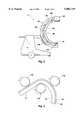
- FIG. 2shows a cross-sectional view of the C-arm frame taken along the lines A--A of FIG. 1, along with a surgical drape which is attached to the frame by a clip.
- FIG. 3shows a side view of a C-arm X-ray diagnostic machine having a surgical drape attached about the inner portion of the C-arm.
- FIG. 4shows a fragmented, side view of a piece of extruded material being formed/rolled into a C-shaped support frame for holding X-ray diagnostic equipment.
- FIGS. 5A-Cshows cross-sectional views similar to that of FIG. 2 for three alternate embodiments of the present invention.
- FIG. 1there is shown a side view of C-arm X-ray diagnostic equipment, generally indicated at 2, made in accordance with the present invention.
- the equipment 2has a wheeled base 6 and a C-shaped support frame 10 connected to the base 6.
- Attached to a lower end 14 of the support frame 10is an X-ray collimator 18.
- Positioned on the upper end 22 of the support frame 10is an image receptor 26 for holding X-ray film and the like.
- the collimator 18 and the image receptor 26are positioned so as to be opposite each other.
- the C-shaped support frame 10has an inner circumference 34, which faces the X-ray diagnostic equipment 18 and 26, and an outer circumference 38 positioned opposite the inner circumference, the lower section of which faces the base 6.
- FIG. 2there is shown a cross-sectional view of the support frame 10 taken along the plane A--A shown in FIG. 1. Due to the location of the cross-sectional view, the inner circumference 34 is positioned at the top of the figure and the outer circumference 38 is positioned at the bottom of the figure. If the cross-section had been taken from the upper portion 22 (FIG. 1) of the support frame 10, the inner circumference 34 would be at the bottom and the outer circumference 38 would be at the top.
- FIG. 2shows a pair of generally vertical sidewalls 40 and 44 which are separated by a pair of generally horizontal support walls 50 and 54.
- the support walls 50 and 54curve in a C-shape such that the support walls are generally horizontal at the lower portion 14 and upper portion 22 of the support arm, but are generally vertical midway between the lower and upper portions.
- a first, inner support wall 50forms the inner circumference 34 of the C-shaped support frame 10.
- the first support wall 50is generally horizontal in the middle, and sloped on each end at about a forty-five degree angle to meet the vertical sidewalls 40 and 44.
- the support wall 50could be semi-circular, or arched.
- the configuration shown in FIG. 2shows the present preferred embodiments for reasons which will be explained when discussing the method of making the support frame 10.
- the second support wall 54is positioned toward the outer circumference 38 of the support frame 10.
- the second support wall 54extends horizontally from each sidewall, 40 and 44, and then has two angled sections 62 and 64 which extend outward (downward) at an angle to meet a generally horizontal section 68 positioned between the two.
- a flange 70extends from the sidewall 40 toward the horizontal section 68, so that the sidewall, the angled section 62 and the flange 70 form a channel 74 adjacent to the outer side 38 of the support frame 10.
- a flange 80extends from the sidewall 44 toward the horizontal section 68, so that the angled section 64, the sidewall 44 and the flange 80 form a channel 84 adjacent to the outer circumference 38 of the support frame 10.
- the cross-sectional view shown in FIG. 2is that of the support frame 10 after it has been rolled into the C-shape shown in FIG. 1.
- the flanges 70 and 80 areaactually angled slightly outward--typically between about five and ten degrees from the sidewalls 40 and 44. This is represented by the dotted lines 70A and 80A adjacent each flange.
- the flanges 70 and 80move into a position generally perpendicular to sidewalls 40 and 44, as shown in FIG. 2.
- the channels 74 and 84enable bearings or wheels to be positioned therein.
- the support frame 10is rotated, thereby positioning the X-ray diagnostic equipment 18 and 26 at a desired angle.
- the second support wall 54could be straight (horizontal in FIG. 2), thereby forming only a single channel, the dual channel arrangement formed by the second support wall 54 provides additional strength and stability. Additionally, the channels 74 and 84 formed thereby allow more control over lateral movement of the wheels or bearings.
- the frame 10 as shown in FIG. 2is formed from a single piece.
- Prior art approacheshad the first support wall and second support wall formed as two separate pieces which were then joined with adhesive, or by welding the two together.
- a two piece frameis usually inferior structurally to one formed of a single piece of material.
- FIG. 2Another aspect of the present invention that is shown in FIG. 2 is a pair of grooves 90 and 94 (equivalent to groove 30 in FIG. 1) formed in the sidewalls 40 and 44 respectively.
- the grooves 90 and 94extend the length of the support frame 10 and enable a surgical drape to be placed about the inner circumference 34 of the support frame 10 to prevent contaminants from passing between the support frame 10 and a patient undergoing surgery.
- FIG. 2Also shown in FIG. 2 is a clip 100 and a surgical drape 110 which is held to the frame 10 by the clip.
- the clip 100is made of a resilient material, such as plastic, and has flanges 104 and 108 which nest in the grooves 90 and 94 to thereby hold the clip about the inner circumference 34 of the support frame 10.
- the surgical drape 110is attached at each end to the clip 100 by fasteners 114 and 118.
- the fasteners 114 and 118can be made of adhesive, formed as snaps, or comprise other fasteners known to those skilled in the art either currently or in the future.
- the surgical drape 110is held to the support frame 10 by placing one of the flanges 104 or 108 of the clip 100 into the respective groove 90 or 94 and deforming the clip slightly until the other flange is adjacent the other groove. Releasing the other flange causes both flanges to nest in the other groove, thereby holding the clip in place.
- the resilient nature of the clip 100keeps the flanges 104 and 108 nested in the grooves 90 and 94 until an external force pulls the flanges from the grooves.
- FIG. 3there is shown a side view of a C-arm similar to that shown in FIG. 1, but having a surgical drape 110 attached by a plurality of clips 100.
- the clipsare anchored in the grooves, of which only groove 90 is shown.
- the purpose of the surgical drape 110is to keep a sterile environment around the support frame 10. This can be difficult as C-arms are often used during surgical procedures. Tissue may fall on the C-arm and body fluids may occasionally spray, contaminating an uncovered support frame 10.
- the surgical drape 110can be quickly and easily removed by disconnecting the clips 100. A new surgical drape can then be attached by another set of clips 100, or by reusing the original set with a new surgical drape/curtain 110.
- a materialsuch as metal or plastic, is extruded from a mold so that it has the desired cross-section. While the cross-section shown in FIG. 2 is a preferred embodiment, numerous other designs will be apparent to those skilled in the art.
- FIG. 4there is shown a side view of an extruded metal frame 10 being passed through rollers 130 to give the frame the desired C shape.
- the originally straight frame 10must be passed through rollers 130 with sufficient curvature so that the extruded material will not "spring” or relax back toward a straight element, but no so significant a curvature that the extruded material kinks, thereby weakening the support frame.
- the exact curvature of the rollerswill depend in large part on design characteristics such as the desired size of the C-arm, the cross-sectional dimensions of the frame and the material from which the frame is made.
- the flat inner circumference 34 (FIG. 2) of the first support wall 50is easier to curve without kinking than is a curved wall.
- the frame 10When using metal, the current preferred embodiment, the frame 10 is rolled at room temperature and a T4 temper. Usually, the frame 10 will be filled with sand or some other incompressible material to prevent the frame 10 from collapsing or kinking during the rolling process. After it has been rolled, the C-shaped frame 10 is heat treated to a T6 temper to provide additional strength. The C-shaped frame 10 can then be attached to X-ray diagnostic or other equipment.
- FIGS. 5A-Cthere are shown three alternate embodiments of the present invention.
- Each embodimentincludes an elongate hollow piece of material.
- the elongate hollow piece of materialshall be referred to as a tube regardless of the cross-section shape of the material.
- FIG. 5Athere is shown a cross-section of a C-arm which a frame 200 including a tube 204 which is generally round and encloses a hollow 208.
- the upper portion 212 of the tube 204(which is analogous in function to the inner support wall in FIG. 2) will form the inner circumference of the C-arm frame.
- the lower portion 216 of the tube 204(which is analogous to the outer support wall in FIG. 2) is positioned adjacent the outer circumference of the C-arm.
- a pair of flanges 220 and 224extend away from the tube 204, and then turn toward each other as to define a channel 228 between the flanges 220 and 224, and adjacent to the lower portion 216.
- bearingsnot shown
- the frame 200can be rotated as described above.
- FIG. 5Bthere is shown a cross-sectional view of a frame 230 which has a tube 234 which is generally rectangular and encloses a hollow 238.
- the tubeincludes sidewalls 238 and 242 which are connected by spaced apart support walls 246 and 250.
- the sidewalls 238 and 242 and the support walls 246 and 250enclose a hollow 254.
- the support wall 246defines an inner circumference of the frame 230.
- the outer circumference of the frame 230is formed by a pair of flanges 260 and 264 which extend from the outer support wall 250 and then turn toward each other to form a channel 268 between the flanges and adjacent the outer support wall.
- a frame 270which includes a triangular tube 274 formed by two sidewalls 278 and 282 which are attached at one end and spaced apart by a support wall 286 at the other end.
- Two flanges 290 and 294extend outward from the tube 274 and then turn towards each other to define a channel 298.
- the flanges 290 and 294define the outer circumference. Bearings (not shown) are positioned in the channel 298 to allow rotation of the frame 270 in the manner describe above.
- the frames 200, 230 and 270are preferably formed of metal in the manner described with respect to the preferred embodiment. However, other materials such as plastic may also be used.
Landscapes
- Health & Medical Sciences (AREA)
- Life Sciences & Earth Sciences (AREA)
- Engineering & Computer Science (AREA)
- Medical Informatics (AREA)
- Surgery (AREA)
- Heart & Thoracic Surgery (AREA)
- Veterinary Medicine (AREA)
- Public Health (AREA)
- General Health & Medical Sciences (AREA)
- Animal Behavior & Ethology (AREA)
- Molecular Biology (AREA)
- Biomedical Technology (AREA)
- High Energy & Nuclear Physics (AREA)
- Radiology & Medical Imaging (AREA)
- Pathology (AREA)
- Optics & Photonics (AREA)
- Nuclear Medicine, Radiotherapy & Molecular Imaging (AREA)
- Physics & Mathematics (AREA)
- Biophysics (AREA)
- Apparatus For Radiation Diagnosis (AREA)
Abstract
Description
This application is a continuation of application Ser. No. 08,425,881 abandoned Jul. 9, 1997, filed on Apr. 21, 1995 which was a divisional of application Ser. No. 08/209,961 filed Mar. 14, 1994 now U.S. Pat. No. 5,426,683.
The present invention relates to a one-piece C-arm for X-ray diagnostic equipment and a method for making the same, and specifically to a seamless C-arm which is formed in a continuous curved piece to obviate the need for attaching two or more pieces together.
The use of "C-arms" for X-ray and other diagnostic equipment in surgical and other diagnostic procedures is well known in the medical arts. The mounting is referred to a C-arm due to the C-shape of the support frame which holds the diagnostic equipment in place. In use, an X-ray collimator or some other diagnostic device is mounted at one end of the frame. An image receptor is located on the other end so that the collimator and receptor are exactly opposite of each other.
There are two primary advantages to the C-shape of the support frame. First, the C-shape allows the diagnostic equipment to travel the length of the patient without interfering with the availability of the patient's body to medical personnel standing on the opposite side of the patient from the diagnostic equipment. Thus, a surgeon can operate on a patient while the C-arm travels up and down the body, ensuring that devices, such as angioplasty balloons, etc., are properly positioned during a procedure. A second advantage of the C-arm is that the arm can be rotated so that the collimator and the receptor are either nearly in the same vertical plane, nearly in the same horizontal plane, or somewhere in between. This rotation allows the radiologist or technician to take X-rays of the patient's body at an optimal angle for the anatomical structure being imaged. When a given patient is finished, the C-arm can be rotated to it original position, ready for the next patient.
One drawback of currently used C-arms is that they are usually formed of several pieces attached together in order to form tracks or channels which receive bearings or wheels to thereby allow the C-arms to rotate in the above described manner. For example, in U.S. Pat. No. 4,955,046, (Siczek et al.) there is shown a C-arm, the frame of which is formed in two pieces. The inner portion of the C-arm is formed in the shape of a flattened arch and attached, through an adhesive or some other manner, to an outer portion. Such a two piece C-arm frame is time consuming to fabricate and join and does not have the strength of a frame formed from a single, integral piece of material.
Another disadvantage of the C-arms of the prior art is that the C-arm is exposed to environmental contaminants. This comes about, for example, when C-arms are used in connection with surgical procedures, and the C-arm contacts bodily fluids, such as blood, or tissue being removed from a patient's body. With the current concern over tissue and fluid borne communicable diseases, it is desirable to keep the support arm free from contact with such contaminants.
In addition to contaminants from patients, the C-arm often encounters bacteria if used outside of the operating room. Such bacteria can be a serious threat to those undergoing surgery. Due to the size of the support arm, it is expensive and time consuming to thoroughly disinfect before each procedure.
Thus, a single piece C-arm formed to the desired shape would be desirable. Additionally, a C-arm which provides a support for a surgical drape/curtain or shield would also be advantageous to prevent contamination of the C-arm.
It is an object of the invention to provide an improved C-arm for use in diagnostic and surgical procedures.
It is another object of the invention to provide a C-arm support frame which is formed from a single piece of material.
It is an additional object of the present invention to provide an economical method for forming a C-arm support frame from a single piece of material.
It is yet another object of the invention to provide a structure for preventing bacteria and other contaminants from being passed between the patient and the C-arm.
The above and other objects of the invention are achieved by a C-arm frame having C-shaped unibody construction with a cross-section which includes two generally vertical sidewalls extending generally parallel to one another, an inner support wall connecting the sidewalls, and an outer support wall spaced apart from the inner support wall and connecting the sidewalls.
In accordance with one aspect of the invention, a pair of flanges extend upwardly from the outer support wall and then inwardly to form at least one channel along an outer portion of the C-arm frame, in which wheels or bearings may be mounted to enable the C-arm to rotate.
In accordance with another aspect of the invention, grooves are formed on the exterior of the vertical sidewalls, for receiving clips which, in turn, hold a surgical drape for preventing contamination of the C-arm.
FIG. 1 shows a C-arm X-ray diagnostic machine made in accordance with a preferred embodiment of the invention.
FIG. 2 shows a cross-sectional view of the C-arm frame taken along the lines A--A of FIG. 1, along with a surgical drape which is attached to the frame by a clip.
FIG. 3 shows a side view of a C-arm X-ray diagnostic machine having a surgical drape attached about the inner portion of the C-arm.
FIG. 4 shows a fragmented, side view of a piece of extruded material being formed/rolled into a C-shaped support frame for holding X-ray diagnostic equipment.
FIGS. 5A-C shows cross-sectional views similar to that of FIG. 2 for three alternate embodiments of the present invention.
Referring to FIG. 1, there is shown a side view of C-arm X-ray diagnostic equipment, generally indicated at 2, made in accordance with the present invention. Theequipment 2 has awheeled base 6 and a C-shaped support frame 10 connected to thebase 6. Attached to alower end 14 of thesupport frame 10 is anX-ray collimator 18. Positioned on theupper end 22 of thesupport frame 10 is animage receptor 26 for holding X-ray film and the like. Thecollimator 18 and theimage receptor 26 are positioned so as to be opposite each other.
Positioned along the walls of thesupport frame 10 is agroove 30 which ideally extends from theupper end 22 to thelower end 14 of thesupport frame 10. The advantages of thegroove 30 will be explained in detail with respect to FIGS. 2 & 3. The C-shaped support frame 10 has aninner circumference 34, which faces the X-raydiagnostic equipment outer circumference 38 positioned opposite the inner circumference, the lower section of which faces thebase 6.
Referring now to FIG. 2, there is shown a cross-sectional view of thesupport frame 10 taken along the plane A--A shown in FIG. 1. Due to the location of the cross-sectional view, theinner circumference 34 is positioned at the top of the figure and theouter circumference 38 is positioned at the bottom of the figure. If the cross-section had been taken from the upper portion 22 (FIG. 1) of thesupport frame 10, theinner circumference 34 would be at the bottom and theouter circumference 38 would be at the top.
The cross-sectional view of FIG. 2 shows a pair of generallyvertical sidewalls horizontal support walls sidewalls support frame 10, thesupport walls lower portion 14 andupper portion 22 of the support arm, but are generally vertical midway between the lower and upper portions.
A first,inner support wall 50 forms theinner circumference 34 of the C-shaped support frame 10. As shown in FIG. 2, thefirst support wall 50 is generally horizontal in the middle, and sloped on each end at about a forty-five degree angle to meet thevertical sidewalls first support wall 50 to give structural support to thesidewalls support frame 10. For example, thesupport wall 50 could be semi-circular, or arched. However, the configuration shown in FIG. 2 shows the present preferred embodiments for reasons which will be explained when discussing the method of making thesupport frame 10.
Thesecond support wall 54 is positioned toward theouter circumference 38 of thesupport frame 10. The first andsecond support walls sidewalls chamber 58 which extends the length of thesupport frame 10. In the preferred embodiment, thesecond support wall 54 extends horizontally from each sidewall, 40 and 44, and then has twoangled sections horizontal section 68 positioned between the two.
Aflange 70 extends from thesidewall 40 toward thehorizontal section 68, so that the sidewall, theangled section 62 and theflange 70 form achannel 74 adjacent to theouter side 38 of thesupport frame 10. Aflange 80 extends from thesidewall 44 toward thehorizontal section 68, so that theangled section 64, thesidewall 44 and theflange 80 form achannel 84 adjacent to theouter circumference 38 of thesupport frame 10.
The cross-sectional view shown in FIG. 2 is that of thesupport frame 10 after it has been rolled into the C-shape shown in FIG. 1. When thesupport frame 10 is extruded, theflanges sidewalls flanges
Thechannels support frame 10 is rotated, thereby positioning the X-raydiagnostic equipment second support wall 54 could be straight (horizontal in FIG. 2), thereby forming only a single channel, the dual channel arrangement formed by thesecond support wall 54 provides additional strength and stability. Additionally, thechannels
An important aspect of thesupport frame 10 as shown in FIG. 2 is that the frame is formed from a single piece. Prior art approaches had the first support wall and second support wall formed as two separate pieces which were then joined with adhesive, or by welding the two together. A two piece frame, however, is usually inferior structurally to one formed of a single piece of material.
Another aspect of the present invention that is shown in FIG. 2 is a pair ofgrooves 90 and 94 (equivalent to groove 30 in FIG. 1) formed in thesidewalls grooves support frame 10 and enable a surgical drape to be placed about theinner circumference 34 of thesupport frame 10 to prevent contaminants from passing between thesupport frame 10 and a patient undergoing surgery.
Also shown in FIG. 2 is aclip 100 and asurgical drape 110 which is held to theframe 10 by the clip. Theclip 100 is made of a resilient material, such as plastic, and hasflanges grooves inner circumference 34 of thesupport frame 10. Thesurgical drape 110 is attached at each end to theclip 100 byfasteners fasteners
Thesurgical drape 110 is held to thesupport frame 10 by placing one of theflanges clip 100 into therespective groove clip 100 keeps theflanges grooves
Referring now to FIG. 3, there is shown a side view of a C-arm similar to that shown in FIG. 1, but having asurgical drape 110 attached by a plurality ofclips 100. The clips are anchored in the grooves, of which only groove 90 is shown. The purpose of thesurgical drape 110 is to keep a sterile environment around thesupport frame 10. This can be difficult as C-arms are often used during surgical procedures. Tissue may fall on the C-arm and body fluids may occasionally spray, contaminating anuncovered support frame 10. By having asurgical drape 110 attached about theinner circumference 34 of thesupport frame 10, the risk of passing contaminants from the support frame to the patient or from the patient to the support frame are greatly reduced. Once a surgical procedure is over, thesurgical drape 110 can be quickly and easily removed by disconnecting theclips 100. A new surgical drape can then be attached by another set ofclips 100, or by reusing the original set with a new surgical drape/curtain 110.
In order to manufacture aunibody support frame 10 as has been described above, a material, such as metal or plastic, is extruded from a mold so that it has the desired cross-section. While the cross-section shown in FIG. 2 is a preferred embodiment, numerous other designs will be apparent to those skilled in the art.
Referring to FIG. 4, there is shown a side view of an extrudedmetal frame 10 being passed throughrollers 130 to give the frame the desired C shape. The originallystraight frame 10 must be passed throughrollers 130 with sufficient curvature so that the extruded material will not "spring" or relax back toward a straight element, but no so significant a curvature that the extruded material kinks, thereby weakening the support frame. The exact curvature of the rollers will depend in large part on design characteristics such as the desired size of the C-arm, the cross-sectional dimensions of the frame and the material from which the frame is made. As was alluded to earlier, the flat inner circumference 34 (FIG. 2) of thefirst support wall 50 is easier to curve without kinking than is a curved wall.
When using metal, the current preferred embodiment, theframe 10 is rolled at room temperature and a T4 temper. Usually, theframe 10 will be filled with sand or some other incompressible material to prevent theframe 10 from collapsing or kinking during the rolling process. After it has been rolled, the C-shapedframe 10 is heat treated to a T6 temper to provide additional strength. The C-shapedframe 10 can then be attached to X-ray diagnostic or other equipment.
Referring now to FIGS. 5A-C, there are shown three alternate embodiments of the present invention. Each embodiment includes an elongate hollow piece of material. For ease of reference, the elongate hollow piece of material shall be referred to as a tube regardless of the cross-section shape of the material. In FIG. 5A there is shown a cross-section of a C-arm which aframe 200 including atube 204 which is generally round and encloses a hollow 208. When bent in a C shape, theupper portion 212 of the tube 204 (which is analogous in function to the inner support wall in FIG. 2) will form the inner circumference of the C-arm frame. Accordingly, thelower portion 216 of the tube 204 (which is analogous to the outer support wall in FIG. 2) is positioned adjacent the outer circumference of the C-arm.
A pair offlanges tube 204, and then turn toward each other as to define achannel 228 between theflanges lower portion 216. When bearings (not shown) are placed in thechannel 224, theframe 200 can be rotated as described above.
Referring now to FIG. 5B, there is shown a cross-sectional view of aframe 230 which has atube 234 which is generally rectangular and encloses a hollow 238. The tube includessidewalls support walls sidewalls support walls
In the C-arm, thesupport wall 246 defines an inner circumference of theframe 230. The outer circumference of theframe 230 is formed by a pair offlanges outer support wall 250 and then turn toward each other to form achannel 268 between the flanges and adjacent the outer support wall.
Referring now to FIG. 5C, there is shown aframe 270 which includes atriangular tube 274 formed by twosidewalls support wall 286 at the other end. Twoflanges tube 274 and then turn towards each other to define achannel 298. In the C-arm, to point at which thesidewalls frame 270, while theflanges channel 298 to allow rotation of theframe 270 in the manner describe above.
With each of these embodiments, theframes
In the manner described above, an improved one-piece C-arm frame for X-ray diagnostic equipment is disclosed. It will be understood that other variations and modifications of the C-arm frame 10 will be apparent to those skilled in the art without departing from the scope of the invention. The C-arm frame described is not meant to be a delineation of the scope of the invention, but merely an example of a present preferred embodiment.
Claims (10)
1. A method for forming a single piece C-arm for use with X-ray diagnostic equipment, the method including the steps of:
(a) extruding a material to form an elongate single piece beam sized with a cross-section including two generally vertical sidewalls connected by spaced-apart support walls configured so as to form a chamber between the two generally vertical sidewalls and spaced-apart support walls, and
(b) successfully passing the single piece beam through a plurality of rollers to curve the single piece beam and forming a generally C-shaped frame defining a C-shaped chamber between the two generally vertical sidewalls and the spaced apart support walls with opposing ends configured for attachment of X-ray diagnostic equipment.
2. The method of claim 1 wherein step (a) further comprises forming two flanges extending from respective sidewalls and generally toward each other to form at least one channel along a section of the single piece beam.
3. The method of claim 1 wherein the material extruded in step (a) is selected from the group consisting of aluminum and plastic.
4. The method of claim 1 wherein step (b) further comprises passing the single piece beam through the rollers while the single piece beam is hot.
5. The method of claim 4 further comprising clamping the single piece beam in a C-shape and allowing the single piece beam to cool.
6. A method for forming a single piece C-arm for use with X-ray diagnostic equipment, the method including the steps of:
(a) extruding a material to form an elongate single piece beam having an enclosed chamber and a pair of outwardly extending flanges configured to define a channel for receiving bearings, and
(b) successfully passing the single piece beam through a plurality of rollers to curve the single piece beam and forming a generally C-shaped frame defining a C-shaped chamber and C-shaped channel between the two generally vertical sidewalls and the spaced apart support walls with opposing ends configured for attachment of X-ray diagnostic equipment.
7. The method of claim 6 wherein step (a) further comprises forming the pair of outwardly extending flanges extending generally toward each other to form the channel for receiving bearings.
8. The method of claim 6 wherein the material extruded in step (a) is selected from the group consisting of aluminum and plastic.
9. The method of claim 6 wherein step (b) further comprises passing the single piece beam through the rollers while the single piece beam is hot.
10. The method of claim 9 further comprising clamping the single piece beam in a C-shape and allowing the single piece beam to cool.
Priority Applications (1)
| Application Number | Priority Date | Filing Date | Title |
|---|---|---|---|
| US08/806,417US5802719A (en) | 1994-03-14 | 1997-02-26 | One piece C-arm for X-ray diagnostic equipment |
Applications Claiming Priority (3)
| Application Number | Priority Date | Filing Date | Title |
|---|---|---|---|
| US08/209,961US5426683A (en) | 1994-03-14 | 1994-03-14 | One piece C-arm for X-ray diagnostic equipment |
| US42588195A | 1995-04-21 | 1995-04-21 | |
| US08/806,417US5802719A (en) | 1994-03-14 | 1997-02-26 | One piece C-arm for X-ray diagnostic equipment |
Related Parent Applications (1)
| Application Number | Title | Priority Date | Filing Date |
|---|---|---|---|
| US42588195AContinuation | 1994-03-14 | 1995-04-21 |
Publications (1)
| Publication Number | Publication Date |
|---|---|
| US5802719Atrue US5802719A (en) | 1998-09-08 |
Family
ID=22781043
Family Applications (3)
| Application Number | Title | Priority Date | Filing Date |
|---|---|---|---|
| US08/209,961Expired - LifetimeUS5426683A (en) | 1994-03-14 | 1994-03-14 | One piece C-arm for X-ray diagnostic equipment |
| US08/426,255Expired - LifetimeUS5506882A (en) | 1994-03-14 | 1995-04-21 | One piece C-arm for X-ray diagnostic equipment |
| US08/806,417Expired - LifetimeUS5802719A (en) | 1994-03-14 | 1997-02-26 | One piece C-arm for X-ray diagnostic equipment |
Family Applications Before (2)
| Application Number | Title | Priority Date | Filing Date |
|---|---|---|---|
| US08/209,961Expired - LifetimeUS5426683A (en) | 1994-03-14 | 1994-03-14 | One piece C-arm for X-ray diagnostic equipment |
| US08/426,255Expired - LifetimeUS5506882A (en) | 1994-03-14 | 1995-04-21 | One piece C-arm for X-ray diagnostic equipment |
Country Status (1)
| Country | Link |
|---|---|
| US (3) | US5426683A (en) |
Cited By (84)
| Publication number | Priority date | Publication date | Assignee | Title |
|---|---|---|---|---|
| USD428490S (en)* | 1998-09-09 | 2000-07-18 | VF Works, Inc | C-arm for a video fluoroscopy device |
| US6118845A (en) | 1998-06-29 | 2000-09-12 | Surgical Navigation Technologies, Inc. | System and methods for the reduction and elimination of image artifacts in the calibration of X-ray imagers |
| US6138489A (en)* | 1997-05-13 | 2000-10-31 | Ab Webra | Method of making a heat transfer device |
| US6470207B1 (en) | 1999-03-23 | 2002-10-22 | Surgical Navigation Technologies, Inc. | Navigational guidance via computer-assisted fluoroscopic imaging |
| US6477400B1 (en) | 1998-08-20 | 2002-11-05 | Sofamor Danek Holdings, Inc. | Fluoroscopic image guided orthopaedic surgery system with intraoperative registration |
| US20020196906A1 (en)* | 1999-07-23 | 2002-12-26 | Inki Mun | Surgical scanning system and process for use thereof |
| US6725080B2 (en) | 2000-03-01 | 2004-04-20 | Surgical Navigation Technologies, Inc. | Multiple cannula image guided tool for image guided procedures |
| US20050047554A1 (en)* | 2003-08-25 | 2005-03-03 | Borom Andrew H. | Attachable surgical table |
| US6892090B2 (en) | 2002-08-19 | 2005-05-10 | Surgical Navigation Technologies, Inc. | Method and apparatus for virtual endoscopy |
| US6920347B2 (en) | 2000-04-07 | 2005-07-19 | Surgical Navigation Technologies, Inc. | Trajectory storage apparatus and method for surgical navigation systems |
| US6947786B2 (en) | 2002-02-28 | 2005-09-20 | Surgical Navigation Technologies, Inc. | Method and apparatus for perspective inversion |
| US6968224B2 (en) | 1999-10-28 | 2005-11-22 | Surgical Navigation Technologies, Inc. | Method of detecting organ matter shift in a patient |
| US6990368B2 (en) | 2002-04-04 | 2006-01-24 | Surgical Navigation Technologies, Inc. | Method and apparatus for virtual digital subtraction angiography |
| US7007699B2 (en) | 1999-10-28 | 2006-03-07 | Surgical Navigation Technologies, Inc. | Surgical sensor |
| USRE39133E1 (en) | 1997-09-24 | 2006-06-13 | Surgical Navigation Technologies, Inc. | Percutaneous registration apparatus and method for use in computer-assisted surgical navigation |
| US7085400B1 (en) | 2000-06-14 | 2006-08-01 | Surgical Navigation Technologies, Inc. | System and method for image based sensor calibration |
| US7108422B2 (en) | 2003-08-25 | 2006-09-19 | Borom Andrew H | Integrated surgical table drape |
| US7174202B2 (en) | 1992-08-14 | 2007-02-06 | British Telecommunications | Medical navigation apparatus |
| US7217276B2 (en) | 1999-04-20 | 2007-05-15 | Surgical Navigational Technologies, Inc. | Instrument guidance method and system for image guided surgery |
| EP1810636A1 (en) | 2006-01-24 | 2007-07-25 | BrainLAB AG | Sterile cover |
| US20070175486A1 (en)* | 2006-01-24 | 2007-08-02 | Brainlab Ag | Sterile drape |
| US7313430B2 (en) | 2003-08-28 | 2007-12-25 | Medtronic Navigation, Inc. | Method and apparatus for performing stereotactic surgery |
| US7366562B2 (en) | 2003-10-17 | 2008-04-29 | Medtronic Navigation, Inc. | Method and apparatus for surgical navigation |
| US7542791B2 (en) | 2003-01-30 | 2009-06-02 | Medtronic Navigation, Inc. | Method and apparatus for preplanning a surgical procedure |
| USRE40852E1 (en) | 1995-06-14 | 2009-07-14 | Medtronic Navigation, Inc. | Method and system for navigating a catheter probe |
| US7567834B2 (en) | 2004-05-03 | 2009-07-28 | Medtronic Navigation, Inc. | Method and apparatus for implantation between two vertebral bodies |
| US7570791B2 (en) | 2003-04-25 | 2009-08-04 | Medtronic Navigation, Inc. | Method and apparatus for performing 2D to 3D registration |
| US20090246923A1 (en)* | 2006-09-20 | 2009-10-01 | Chanho Park | Method of Forming Shielded Gate FET with Self-aligned Features |
| US7599730B2 (en) | 2002-11-19 | 2009-10-06 | Medtronic Navigation, Inc. | Navigation system for cardiac therapies |
| US7636595B2 (en) | 2004-10-28 | 2009-12-22 | Medtronic Navigation, Inc. | Method and apparatus for calibrating non-linear instruments |
| US7657300B2 (en) | 1999-10-28 | 2010-02-02 | Medtronic Navigation, Inc. | Registration of human anatomy integrated for electromagnetic localization |
| US7660623B2 (en) | 2003-01-30 | 2010-02-09 | Medtronic Navigation, Inc. | Six degree of freedom alignment display for medical procedures |
| US7697972B2 (en) | 2002-11-19 | 2010-04-13 | Medtronic Navigation, Inc. | Navigation system for cardiac therapies |
| US7763035B2 (en) | 1997-12-12 | 2010-07-27 | Medtronic Navigation, Inc. | Image guided spinal surgery guide, system and method for use thereof |
| US7797032B2 (en) | 1999-10-28 | 2010-09-14 | Medtronic Navigation, Inc. | Method and system for navigating a catheter probe in the presence of field-influencing objects |
| US7835784B2 (en) | 2005-09-21 | 2010-11-16 | Medtronic Navigation, Inc. | Method and apparatus for positioning a reference frame |
| US7835778B2 (en) | 2003-10-16 | 2010-11-16 | Medtronic Navigation, Inc. | Method and apparatus for surgical navigation of a multiple piece construct for implantation |
| US7840253B2 (en) | 2003-10-17 | 2010-11-23 | Medtronic Navigation, Inc. | Method and apparatus for surgical navigation |
| US20110041995A1 (en)* | 2009-08-21 | 2011-02-24 | Ecolab Usa Inc. | Universal c arm tape drape |
| US7998062B2 (en) | 2004-03-29 | 2011-08-16 | Superdimension, Ltd. | Endoscope structures and techniques for navigating to a target in branched structure |
| US8074662B2 (en) | 1999-10-28 | 2011-12-13 | Medtronic Navigation, Inc. | Surgical communication and power system |
| US8112292B2 (en) | 2006-04-21 | 2012-02-07 | Medtronic Navigation, Inc. | Method and apparatus for optimizing a therapy |
| USRE43328E1 (en) | 1997-11-20 | 2012-04-24 | Medtronic Navigation, Inc | Image guided awl/tap/screwdriver |
| US8165658B2 (en) | 2008-09-26 | 2012-04-24 | Medtronic, Inc. | Method and apparatus for positioning a guide relative to a base |
| US8175681B2 (en) | 2008-12-16 | 2012-05-08 | Medtronic Navigation Inc. | Combination of electromagnetic and electropotential localization |
| US8239001B2 (en) | 2003-10-17 | 2012-08-07 | Medtronic Navigation, Inc. | Method and apparatus for surgical navigation |
| USRE43952E1 (en) | 1989-10-05 | 2013-01-29 | Medtronic Navigation, Inc. | Interactive system for local intervention inside a non-homogeneous structure |
| US8452068B2 (en) | 2008-06-06 | 2013-05-28 | Covidien Lp | Hybrid registration method |
| US8473032B2 (en) | 2008-06-03 | 2013-06-25 | Superdimension, Ltd. | Feature-based registration method |
| US8494614B2 (en) | 2009-08-31 | 2013-07-23 | Regents Of The University Of Minnesota | Combination localization system |
| US8494613B2 (en) | 2009-08-31 | 2013-07-23 | Medtronic, Inc. | Combination localization system |
| US8611984B2 (en) | 2009-04-08 | 2013-12-17 | Covidien Lp | Locatable catheter |
| US8644907B2 (en) | 1999-10-28 | 2014-02-04 | Medtronic Navigaton, Inc. | Method and apparatus for surgical navigation |
| US8660635B2 (en) | 2006-09-29 | 2014-02-25 | Medtronic, Inc. | Method and apparatus for optimizing a computer assisted surgical procedure |
| US8663088B2 (en) | 2003-09-15 | 2014-03-04 | Covidien Lp | System of accessories for use with bronchoscopes |
| US8764725B2 (en) | 2004-02-09 | 2014-07-01 | Covidien Lp | Directional anchoring mechanism, method and applications thereof |
| US8905920B2 (en) | 2007-09-27 | 2014-12-09 | Covidien Lp | Bronchoscope adapter and method |
| US8932207B2 (en) | 2008-07-10 | 2015-01-13 | Covidien Lp | Integrated multi-functional endoscopic tool |
| US9055881B2 (en) | 2004-04-26 | 2015-06-16 | Super Dimension Ltd. | System and method for image-based alignment of an endoscope |
| US9168102B2 (en) | 2006-01-18 | 2015-10-27 | Medtronic Navigation, Inc. | Method and apparatus for providing a container to a sterile environment |
| US20160066871A1 (en)* | 2004-07-30 | 2016-03-10 | Neurologica Corp. | Anatomical imaging system with centipede belt drive |
| USD757270S1 (en)* | 2011-08-30 | 2016-05-24 | Canon Kabushiki Kaisha | X-ray device for medical treatment |
| US20160319967A1 (en)* | 2015-04-28 | 2016-11-03 | Unilok Corporation | Method for manufacturing stop collar for pipe fitting device and stop collar |
| US9575140B2 (en) | 2008-04-03 | 2017-02-21 | Covidien Lp | Magnetic interference detection system and method |
| US9675424B2 (en) | 2001-06-04 | 2017-06-13 | Surgical Navigation Technologies, Inc. | Method for calibrating a navigation system |
| US10178981B2 (en) | 2004-07-30 | 2019-01-15 | Neurologica Corp. | Anatomical imaging system with centipede scanning drive, bottom notch to accommodate base of patient support, and motorized drive for transporting the system between scanning locations |
| US10418705B2 (en) | 2016-10-28 | 2019-09-17 | Covidien Lp | Electromagnetic navigation antenna assembly and electromagnetic navigation system including the same |
| US10426555B2 (en) | 2015-06-03 | 2019-10-01 | Covidien Lp | Medical instrument with sensor for use in a system and method for electromagnetic navigation |
| US10446931B2 (en) | 2016-10-28 | 2019-10-15 | Covidien Lp | Electromagnetic navigation antenna assembly and electromagnetic navigation system including the same |
| US10478254B2 (en) | 2016-05-16 | 2019-11-19 | Covidien Lp | System and method to access lung tissue |
| US10517505B2 (en) | 2016-10-28 | 2019-12-31 | Covidien Lp | Systems, methods, and computer-readable media for optimizing an electromagnetic navigation system |
| US10582834B2 (en) | 2010-06-15 | 2020-03-10 | Covidien Lp | Locatable expandable working channel and method |
| US10615500B2 (en) | 2016-10-28 | 2020-04-07 | Covidien Lp | System and method for designing electromagnetic navigation antenna assemblies |
| US10638952B2 (en) | 2016-10-28 | 2020-05-05 | Covidien Lp | Methods, systems, and computer-readable media for calibrating an electromagnetic navigation system |
| US10722311B2 (en) | 2016-10-28 | 2020-07-28 | Covidien Lp | System and method for identifying a location and/or an orientation of an electromagnetic sensor based on a map |
| US10751126B2 (en) | 2016-10-28 | 2020-08-25 | Covidien Lp | System and method for generating a map for electromagnetic navigation |
| US10792106B2 (en) | 2016-10-28 | 2020-10-06 | Covidien Lp | System for calibrating an electromagnetic navigation system |
| US10952593B2 (en) | 2014-06-10 | 2021-03-23 | Covidien Lp | Bronchoscope adapter |
| US11006914B2 (en) | 2015-10-28 | 2021-05-18 | Medtronic Navigation, Inc. | Apparatus and method for maintaining image quality while minimizing x-ray dosage of a patient |
| US11219489B2 (en) | 2017-10-31 | 2022-01-11 | Covidien Lp | Devices and systems for providing sensors in parallel with medical tools |
| US11246549B2 (en) | 2019-04-19 | 2022-02-15 | Microtek Medical Inc. | Sterile drape with elasticized body portion for protecting a C-arm imaging machine |
| US11298093B2 (en) | 2004-07-30 | 2022-04-12 | Neurologica Corp. | Anatomical imaging system with centipede belt drive |
| US11331150B2 (en) | 1999-10-28 | 2022-05-17 | Medtronic Navigation, Inc. | Method and apparatus for surgical navigation |
| US12089902B2 (en) | 2019-07-30 | 2024-09-17 | Coviden Lp | Cone beam and 3D fluoroscope lung navigation |
Families Citing this family (20)
| Publication number | Priority date | Publication date | Assignee | Title |
|---|---|---|---|---|
| WO1996018341A1 (en)* | 1994-12-12 | 1996-06-20 | Philips Electronics N.V. | Medical diagnostic and/or therapeutic apparatus comprising a c-arc composed of profiles |
| DE19532965C2 (en)* | 1995-09-07 | 1998-07-16 | Heimann Systems Gmbh & Co | X-ray inspection system for large-volume goods |
| DE19746079C2 (en)* | 1997-10-17 | 1999-10-28 | Siemens Ag | Medical facility with a carrying device for at least one component |
| US6374937B1 (en) | 1998-05-29 | 2002-04-23 | John Galando | Motorized support for imaging means and methods of manufacture and use thereof |
| US6131690A (en)* | 1998-05-29 | 2000-10-17 | Galando; John | Motorized support for imaging means |
| US6142667A (en)* | 1998-09-21 | 2000-11-07 | Oec Medical Systems, Inc. | Gas-spring assisted, counter-balanced L-arm assembly for fluoroscopic imaging |
| US20040176668A1 (en)* | 2000-08-15 | 2004-09-09 | Goldstein James A. | Support and sensing apparatus |
| US6448571B1 (en)* | 2000-08-15 | 2002-09-10 | James A. Goldstein | Radiation protection system |
| US7057194B2 (en)* | 2004-04-07 | 2006-06-06 | Eco Cath-Lab Systems, Inc. | Radiation barrier |
| US7829873B2 (en)* | 2006-07-28 | 2010-11-09 | Eco Cath-Lab Systems, Inc. | Lower shield for radiation protection system |
| DE102008003816B4 (en)* | 2008-01-10 | 2013-08-01 | Siemens Aktiengesellschaft | X-ray device comprising a preferably rotatably mounted on a robot arm C-arm |
| EP2408375B1 (en) | 2009-03-20 | 2017-12-06 | Orthoscan Incorporated | Moveable imaging apparatus |
| WO2012082799A1 (en) | 2010-12-13 | 2012-06-21 | Orthoscan, Inc. | Mobile fluoroscopic imaging system |
| GB2491345A (en) | 2011-05-21 | 2012-12-05 | Kuester Medical Ltd | Clip for sterile cover |
| EP2736412A4 (en)* | 2011-07-29 | 2015-02-25 | Contour Fabricators Inc | Fluoroscopy c-arm drape clip, drape clip assembly and method of clipping a sterile drape to a fluoroscopy c-arm |
| US9295521B2 (en)* | 2013-12-20 | 2016-03-29 | General Electric Company | Sterile drapes for X-ray devices, systems containing the same, and methods for using the same |
| GB2547575B (en) | 2014-09-29 | 2019-04-10 | Shanghai United Imaging Healthcare Co Ltd | System and method for digital radiography |
| US10835337B2 (en) | 2017-02-02 | 2020-11-17 | Tidi Products, Llc | Sterile imaging protective system |
| US11412999B2 (en)* | 2019-11-20 | 2022-08-16 | GE Precision Healthcare LLC | Methods and systems for a medical imaging system with C-arm |
| DE102023205041B4 (en) | 2023-05-30 | 2025-02-06 | Siemens Healthineers Ag | support frame for an angiography system |
Citations (5)
| Publication number | Priority date | Publication date | Assignee | Title |
|---|---|---|---|---|
| US3742748A (en)* | 1970-07-03 | 1973-07-03 | Demag Ag | Method and apparatus for producing an annular collar from a pipe in a hot state |
| US4204309A (en)* | 1977-05-13 | 1980-05-27 | Compagnie Generale Des Etablissements Michelin | Process of fabricating hollow bead rings |
| US4432123A (en)* | 1979-11-15 | 1984-02-21 | Uhde Gmbh | Process for the manufacture of double walled pipe |
| US4977771A (en)* | 1988-12-30 | 1990-12-18 | Usui Kokusai Sangyo Kaisha Ltd. | Device for bending thin metallic pipe |
| US5104026A (en)* | 1990-03-26 | 1992-04-14 | Shape Corporation | Apparatus for roll-forming an automotive bumper |
Family Cites Families (4)
| Publication number | Priority date | Publication date | Assignee | Title |
|---|---|---|---|---|
| NL8801750A (en)* | 1988-07-11 | 1990-02-01 | Philips Nv | ROENTGEN RESEARCH DEVICE WITH A BALANCED TRIPOD. |
| US4977585A (en)* | 1989-04-05 | 1990-12-11 | Imatron, Inc. | Self shielded computerized tomographic scanner |
| US5122904A (en)* | 1989-10-23 | 1992-06-16 | Olympus Optical Co., Ltd. | Operating microscope with drape and suction means for removing air from the drape |
| US5417225A (en)* | 1993-09-03 | 1995-05-23 | Georgetown University | Surgical radiation shield having an opening for tube insertion and a slit for shield removal without tube removal |
- 1994
- 1994-03-14USUS08/209,961patent/US5426683A/ennot_activeExpired - Lifetime
- 1995
- 1995-04-21USUS08/426,255patent/US5506882A/ennot_activeExpired - Lifetime
- 1997
- 1997-02-26USUS08/806,417patent/US5802719A/ennot_activeExpired - Lifetime
Patent Citations (5)
| Publication number | Priority date | Publication date | Assignee | Title |
|---|---|---|---|---|
| US3742748A (en)* | 1970-07-03 | 1973-07-03 | Demag Ag | Method and apparatus for producing an annular collar from a pipe in a hot state |
| US4204309A (en)* | 1977-05-13 | 1980-05-27 | Compagnie Generale Des Etablissements Michelin | Process of fabricating hollow bead rings |
| US4432123A (en)* | 1979-11-15 | 1984-02-21 | Uhde Gmbh | Process for the manufacture of double walled pipe |
| US4977771A (en)* | 1988-12-30 | 1990-12-18 | Usui Kokusai Sangyo Kaisha Ltd. | Device for bending thin metallic pipe |
| US5104026A (en)* | 1990-03-26 | 1992-04-14 | Shape Corporation | Apparatus for roll-forming an automotive bumper |
Cited By (178)
| Publication number | Priority date | Publication date | Assignee | Title |
|---|---|---|---|---|
| USRE43952E1 (en) | 1989-10-05 | 2013-01-29 | Medtronic Navigation, Inc. | Interactive system for local intervention inside a non-homogeneous structure |
| US7174202B2 (en) | 1992-08-14 | 2007-02-06 | British Telecommunications | Medical navigation apparatus |
| US8200314B2 (en) | 1992-08-14 | 2012-06-12 | British Telecommunications Public Limited Company | Surgical navigation |
| USRE43750E1 (en) | 1995-06-14 | 2012-10-16 | Medtronic Navigation, Inc. | Method for navigating a catheter probe |
| USRE40852E1 (en) | 1995-06-14 | 2009-07-14 | Medtronic Navigation, Inc. | Method and system for navigating a catheter probe |
| USRE41066E1 (en) | 1995-06-14 | 2009-12-29 | Metronic Navigation, Inc. | Method and system for navigating a catheter probe |
| US6138489A (en)* | 1997-05-13 | 2000-10-31 | Ab Webra | Method of making a heat transfer device |
| USRE44305E1 (en) | 1997-09-24 | 2013-06-18 | Medtronic Navigation, Inc. | Percutaneous registration apparatus and method for use in computer-assisted surgical navigation |
| USRE42194E1 (en) | 1997-09-24 | 2011-03-01 | Medtronic Navigation, Inc. | Percutaneous registration apparatus and method for use in computer-assisted surgical navigation |
| USRE39133E1 (en) | 1997-09-24 | 2006-06-13 | Surgical Navigation Technologies, Inc. | Percutaneous registration apparatus and method for use in computer-assisted surgical navigation |
| USRE42226E1 (en) | 1997-09-24 | 2011-03-15 | Medtronic Navigation, Inc. | Percutaneous registration apparatus and method for use in computer-assisted surgical navigation |
| USRE46409E1 (en) | 1997-11-20 | 2017-05-23 | Medtronic Navigation, Inc. | Image guided awl/tap/screwdriver |
| USRE46422E1 (en) | 1997-11-20 | 2017-06-06 | Medtronic Navigation, Inc. | Image guided awl/tap/screwdriver |
| USRE43328E1 (en) | 1997-11-20 | 2012-04-24 | Medtronic Navigation, Inc | Image guided awl/tap/screwdriver |
| US7763035B2 (en) | 1997-12-12 | 2010-07-27 | Medtronic Navigation, Inc. | Image guided spinal surgery guide, system and method for use thereof |
| US8105339B2 (en) | 1997-12-12 | 2012-01-31 | Sofamor Danek Holdings, Inc. | Image guided spinal surgery guide system and method for use thereof |
| US6370224B1 (en) | 1998-06-29 | 2002-04-09 | Sofamor Danek Group, Inc. | System and methods for the reduction and elimination of image artifacts in the calibration of x-ray imagers |
| US6118845A (en) | 1998-06-29 | 2000-09-12 | Surgical Navigation Technologies, Inc. | System and methods for the reduction and elimination of image artifacts in the calibration of X-ray imagers |
| US7130676B2 (en) | 1998-08-20 | 2006-10-31 | Sofamor Danek Holdings, Inc. | Fluoroscopic image guided orthopaedic surgery system with intraoperative registration |
| US8768437B2 (en) | 1998-08-20 | 2014-07-01 | Sofamor Danek Holdings, Inc. | Fluoroscopic image guided surgery system with intraoperative registration |
| US6477400B1 (en) | 1998-08-20 | 2002-11-05 | Sofamor Danek Holdings, Inc. | Fluoroscopic image guided orthopaedic surgery system with intraoperative registration |
| USD428490S (en)* | 1998-09-09 | 2000-07-18 | VF Works, Inc | C-arm for a video fluoroscopy device |
| US7996064B2 (en) | 1999-03-23 | 2011-08-09 | Medtronic Navigation, Inc. | System and method for placing and determining an appropriately sized surgical implant |
| US7606613B2 (en) | 1999-03-23 | 2009-10-20 | Medtronic Navigation, Inc. | Navigational guidance via computer-assisted fluoroscopic imaging |
| US6470207B1 (en) | 1999-03-23 | 2002-10-22 | Surgical Navigation Technologies, Inc. | Navigational guidance via computer-assisted fluoroscopic imaging |
| US8845655B2 (en) | 1999-04-20 | 2014-09-30 | Medtronic Navigation, Inc. | Instrument guide system |
| US7217276B2 (en) | 1999-04-20 | 2007-05-15 | Surgical Navigational Technologies, Inc. | Instrument guidance method and system for image guided surgery |
| US6857778B2 (en) | 1999-07-23 | 2005-02-22 | Inki Mun | Surgical scanning system and process for use thereof |
| EP1211980A4 (en)* | 1999-07-23 | 2003-05-14 | Allen Bernard Kantrowitz | Surgical scanning system and process for use thereof |
| US20020196906A1 (en)* | 1999-07-23 | 2002-12-26 | Inki Mun | Surgical scanning system and process for use thereof |
| US7797032B2 (en) | 1999-10-28 | 2010-09-14 | Medtronic Navigation, Inc. | Method and system for navigating a catheter probe in the presence of field-influencing objects |
| US6968224B2 (en) | 1999-10-28 | 2005-11-22 | Surgical Navigation Technologies, Inc. | Method of detecting organ matter shift in a patient |
| US9504530B2 (en) | 1999-10-28 | 2016-11-29 | Medtronic Navigation, Inc. | Method and apparatus for surgical navigation |
| US8057407B2 (en) | 1999-10-28 | 2011-11-15 | Medtronic Navigation, Inc. | Surgical sensor |
| US8548565B2 (en) | 1999-10-28 | 2013-10-01 | Medtronic Navigation, Inc. | Registration of human anatomy integrated for electromagnetic localization |
| US8644907B2 (en) | 1999-10-28 | 2014-02-04 | Medtronic Navigaton, Inc. | Method and apparatus for surgical navigation |
| US8290572B2 (en) | 1999-10-28 | 2012-10-16 | Medtronic Navigation, Inc. | Method and system for navigating a catheter probe in the presence of field-influencing objects |
| US11331150B2 (en) | 1999-10-28 | 2022-05-17 | Medtronic Navigation, Inc. | Method and apparatus for surgical navigation |
| US7657300B2 (en) | 1999-10-28 | 2010-02-02 | Medtronic Navigation, Inc. | Registration of human anatomy integrated for electromagnetic localization |
| US8074662B2 (en) | 1999-10-28 | 2011-12-13 | Medtronic Navigation, Inc. | Surgical communication and power system |
| US7007699B2 (en) | 1999-10-28 | 2006-03-07 | Surgical Navigation Technologies, Inc. | Surgical sensor |
| US10898153B2 (en) | 2000-03-01 | 2021-01-26 | Medtronic Navigation, Inc. | Multiple cannula image guided tool for image guided procedures |
| US6725080B2 (en) | 2000-03-01 | 2004-04-20 | Surgical Navigation Technologies, Inc. | Multiple cannula image guided tool for image guided procedures |
| US7881770B2 (en) | 2000-03-01 | 2011-02-01 | Medtronic Navigation, Inc. | Multiple cannula image guided tool for image guided procedures |
| US7853305B2 (en) | 2000-04-07 | 2010-12-14 | Medtronic Navigation, Inc. | Trajectory storage apparatus and method for surgical navigation systems |
| US6920347B2 (en) | 2000-04-07 | 2005-07-19 | Surgical Navigation Technologies, Inc. | Trajectory storage apparatus and method for surgical navigation systems |
| US8634897B2 (en) | 2000-04-07 | 2014-01-21 | Medtronic Navigation, Inc. | Trajectory storage apparatus and method for surgical navigation systems |
| US7085400B1 (en) | 2000-06-14 | 2006-08-01 | Surgical Navigation Technologies, Inc. | System and method for image based sensor calibration |
| US7831082B2 (en) | 2000-06-14 | 2010-11-09 | Medtronic Navigation, Inc. | System and method for image based sensor calibration |
| US8320653B2 (en) | 2000-06-14 | 2012-11-27 | Medtronic Navigation, Inc. | System and method for image based sensor calibration |
| US9675424B2 (en) | 2001-06-04 | 2017-06-13 | Surgical Navigation Technologies, Inc. | Method for calibrating a navigation system |
| US7630753B2 (en) | 2002-02-28 | 2009-12-08 | Medtronic Navigation, Inc. | Method and apparatus for perspective inversion |
| US9757087B2 (en) | 2002-02-28 | 2017-09-12 | Medtronic Navigation, Inc. | Method and apparatus for perspective inversion |
| US6947786B2 (en) | 2002-02-28 | 2005-09-20 | Surgical Navigation Technologies, Inc. | Method and apparatus for perspective inversion |
| US6990368B2 (en) | 2002-04-04 | 2006-01-24 | Surgical Navigation Technologies, Inc. | Method and apparatus for virtual digital subtraction angiography |
| US8838199B2 (en) | 2002-04-04 | 2014-09-16 | Medtronic Navigation, Inc. | Method and apparatus for virtual digital subtraction angiography |
| US9642514B2 (en) | 2002-04-17 | 2017-05-09 | Covidien Lp | Endoscope structures and techniques for navigating to a target in a branched structure |
| US8696548B2 (en) | 2002-04-17 | 2014-04-15 | Covidien Lp | Endoscope structures and techniques for navigating to a target in branched structure |
| US10743748B2 (en) | 2002-04-17 | 2020-08-18 | Covidien Lp | Endoscope structures and techniques for navigating to a target in branched structure |
| US8696685B2 (en) | 2002-04-17 | 2014-04-15 | Covidien Lp | Endoscope structures and techniques for navigating to a target in branched structure |
| US6892090B2 (en) | 2002-08-19 | 2005-05-10 | Surgical Navigation Technologies, Inc. | Method and apparatus for virtual endoscopy |
| US8046052B2 (en) | 2002-11-19 | 2011-10-25 | Medtronic Navigation, Inc. | Navigation system for cardiac therapies |
| US7599730B2 (en) | 2002-11-19 | 2009-10-06 | Medtronic Navigation, Inc. | Navigation system for cardiac therapies |
| US8060185B2 (en) | 2002-11-19 | 2011-11-15 | Medtronic Navigation, Inc. | Navigation system for cardiac therapies |
| US7697972B2 (en) | 2002-11-19 | 2010-04-13 | Medtronic Navigation, Inc. | Navigation system for cardiac therapies |
| US8401616B2 (en) | 2002-11-19 | 2013-03-19 | Medtronic Navigation, Inc. | Navigation system for cardiac therapies |
| US8467853B2 (en) | 2002-11-19 | 2013-06-18 | Medtronic Navigation, Inc. | Navigation system for cardiac therapies |
| US7974677B2 (en) | 2003-01-30 | 2011-07-05 | Medtronic Navigation, Inc. | Method and apparatus for preplanning a surgical procedure |
| US11684491B2 (en) | 2003-01-30 | 2023-06-27 | Medtronic Navigation, Inc. | Method and apparatus for post-operative tuning of a spinal implant |
| US11707363B2 (en) | 2003-01-30 | 2023-07-25 | Medtronic Navigation, Inc. | Method and apparatus for post-operative tuning of a spinal implant |
| US9867721B2 (en) | 2003-01-30 | 2018-01-16 | Medtronic Navigation, Inc. | Method and apparatus for post-operative tuning of a spinal implant |
| US7542791B2 (en) | 2003-01-30 | 2009-06-02 | Medtronic Navigation, Inc. | Method and apparatus for preplanning a surgical procedure |
| US7660623B2 (en) | 2003-01-30 | 2010-02-09 | Medtronic Navigation, Inc. | Six degree of freedom alignment display for medical procedures |
| US7570791B2 (en) | 2003-04-25 | 2009-08-04 | Medtronic Navigation, Inc. | Method and apparatus for performing 2D to 3D registration |
| US7108422B2 (en) | 2003-08-25 | 2006-09-19 | Borom Andrew H | Integrated surgical table drape |
| US20050047554A1 (en)* | 2003-08-25 | 2005-03-03 | Borom Andrew H. | Attachable surgical table |
| US6984066B2 (en) | 2003-08-25 | 2006-01-10 | Borom Andrew H | Attachable surgical table |
| US7313430B2 (en) | 2003-08-28 | 2007-12-25 | Medtronic Navigation, Inc. | Method and apparatus for performing stereotactic surgery |
| US7925328B2 (en) | 2003-08-28 | 2011-04-12 | Medtronic Navigation, Inc. | Method and apparatus for performing stereotactic surgery |
| US9089261B2 (en) | 2003-09-15 | 2015-07-28 | Covidien Lp | System of accessories for use with bronchoscopes |
| US8663088B2 (en) | 2003-09-15 | 2014-03-04 | Covidien Lp | System of accessories for use with bronchoscopes |
| US10383509B2 (en) | 2003-09-15 | 2019-08-20 | Covidien Lp | System of accessories for use with bronchoscopes |
| US8706185B2 (en) | 2003-10-16 | 2014-04-22 | Medtronic Navigation, Inc. | Method and apparatus for surgical navigation of a multiple piece construct for implantation |
| US7835778B2 (en) | 2003-10-16 | 2010-11-16 | Medtronic Navigation, Inc. | Method and apparatus for surgical navigation of a multiple piece construct for implantation |
| US8549732B2 (en) | 2003-10-17 | 2013-10-08 | Medtronic Navigation, Inc. | Method of forming an electromagnetic sensing coil in a medical instrument |
| US7971341B2 (en) | 2003-10-17 | 2011-07-05 | Medtronic Navigation, Inc. | Method of forming an electromagnetic sensing coil in a medical instrument for a surgical navigation system |
| US7366562B2 (en) | 2003-10-17 | 2008-04-29 | Medtronic Navigation, Inc. | Method and apparatus for surgical navigation |
| US7840253B2 (en) | 2003-10-17 | 2010-11-23 | Medtronic Navigation, Inc. | Method and apparatus for surgical navigation |
| US8239001B2 (en) | 2003-10-17 | 2012-08-07 | Medtronic Navigation, Inc. | Method and apparatus for surgical navigation |
| US8271069B2 (en) | 2003-10-17 | 2012-09-18 | Medtronic Navigation, Inc. | Method and apparatus for surgical navigation |
| US8359730B2 (en) | 2003-10-17 | 2013-01-29 | Medtronic Navigation, Inc. | Method of forming an electromagnetic sensing coil in a medical instrument |
| US7751865B2 (en) | 2003-10-17 | 2010-07-06 | Medtronic Navigation, Inc. | Method and apparatus for surgical navigation |
| US7818044B2 (en) | 2003-10-17 | 2010-10-19 | Medtronic Navigation, Inc. | Method and apparatus for surgical navigation |
| US8764725B2 (en) | 2004-02-09 | 2014-07-01 | Covidien Lp | Directional anchoring mechanism, method and applications thereof |
| US7998062B2 (en) | 2004-03-29 | 2011-08-16 | Superdimension, Ltd. | Endoscope structures and techniques for navigating to a target in branched structure |
| US9055881B2 (en) | 2004-04-26 | 2015-06-16 | Super Dimension Ltd. | System and method for image-based alignment of an endoscope |
| US10321803B2 (en) | 2004-04-26 | 2019-06-18 | Covidien Lp | System and method for image-based alignment of an endoscope |
| US7953471B2 (en) | 2004-05-03 | 2011-05-31 | Medtronic Navigation, Inc. | Method and apparatus for implantation between two vertebral bodies |
| US7567834B2 (en) | 2004-05-03 | 2009-07-28 | Medtronic Navigation, Inc. | Method and apparatus for implantation between two vertebral bodies |
| US11883218B2 (en) | 2004-07-30 | 2024-01-30 | Neurologica Corp. | Anatomical imaging system with centipede belt drive |
| US11298093B2 (en) | 2004-07-30 | 2022-04-12 | Neurologica Corp. | Anatomical imaging system with centipede belt drive |
| US9820704B2 (en)* | 2004-07-30 | 2017-11-21 | Neurologica Corp. | Anatomical imaging system with centipede belt drive |
| US20160066871A1 (en)* | 2004-07-30 | 2016-03-10 | Neurologica Corp. | Anatomical imaging system with centipede belt drive |
| US10178981B2 (en) | 2004-07-30 | 2019-01-15 | Neurologica Corp. | Anatomical imaging system with centipede scanning drive, bottom notch to accommodate base of patient support, and motorized drive for transporting the system between scanning locations |
| US10548545B2 (en) | 2004-07-30 | 2020-02-04 | Neurologica Corp. | Anatomical imaging system with centipede belt drive |
| US7636595B2 (en) | 2004-10-28 | 2009-12-22 | Medtronic Navigation, Inc. | Method and apparatus for calibrating non-linear instruments |
| US7835784B2 (en) | 2005-09-21 | 2010-11-16 | Medtronic Navigation, Inc. | Method and apparatus for positioning a reference frame |
| US8467851B2 (en) | 2005-09-21 | 2013-06-18 | Medtronic Navigation, Inc. | Method and apparatus for positioning a reference frame |
| US9168102B2 (en) | 2006-01-18 | 2015-10-27 | Medtronic Navigation, Inc. | Method and apparatus for providing a container to a sterile environment |
| US10597178B2 (en) | 2006-01-18 | 2020-03-24 | Medtronic Navigation, Inc. | Method and apparatus for providing a container to a sterile environment |
| EP1810636A1 (en) | 2006-01-24 | 2007-07-25 | BrainLAB AG | Sterile cover |
| US8662082B2 (en) | 2006-01-24 | 2014-03-04 | Brainlab Ag | Sterile drape |
| US20070175486A1 (en)* | 2006-01-24 | 2007-08-02 | Brainlab Ag | Sterile drape |
| US8112292B2 (en) | 2006-04-21 | 2012-02-07 | Medtronic Navigation, Inc. | Method and apparatus for optimizing a therapy |
| US20090246923A1 (en)* | 2006-09-20 | 2009-10-01 | Chanho Park | Method of Forming Shielded Gate FET with Self-aligned Features |
| US8660635B2 (en) | 2006-09-29 | 2014-02-25 | Medtronic, Inc. | Method and apparatus for optimizing a computer assisted surgical procedure |
| US9597154B2 (en) | 2006-09-29 | 2017-03-21 | Medtronic, Inc. | Method and apparatus for optimizing a computer assisted surgical procedure |
| US9986895B2 (en) | 2007-09-27 | 2018-06-05 | Covidien Lp | Bronchoscope adapter and method |
| US10980400B2 (en) | 2007-09-27 | 2021-04-20 | Covidien Lp | Bronchoscope adapter and method |
| US9668639B2 (en) | 2007-09-27 | 2017-06-06 | Covidien Lp | Bronchoscope adapter and method |
| US8905920B2 (en) | 2007-09-27 | 2014-12-09 | Covidien Lp | Bronchoscope adapter and method |
| US10390686B2 (en) | 2007-09-27 | 2019-08-27 | Covidien Lp | Bronchoscope adapter and method |
| US9575140B2 (en) | 2008-04-03 | 2017-02-21 | Covidien Lp | Magnetic interference detection system and method |
| US11783498B2 (en) | 2008-06-03 | 2023-10-10 | Covidien Lp | Feature-based registration method |
| US9117258B2 (en) | 2008-06-03 | 2015-08-25 | Covidien Lp | Feature-based registration method |
| US9659374B2 (en) | 2008-06-03 | 2017-05-23 | Covidien Lp | Feature-based registration method |
| US10096126B2 (en) | 2008-06-03 | 2018-10-09 | Covidien Lp | Feature-based registration method |
| US11074702B2 (en) | 2008-06-03 | 2021-07-27 | Covidien Lp | Feature-based registration method |
| US8473032B2 (en) | 2008-06-03 | 2013-06-25 | Superdimension, Ltd. | Feature-based registration method |
| US8452068B2 (en) | 2008-06-06 | 2013-05-28 | Covidien Lp | Hybrid registration method |
| US10674936B2 (en) | 2008-06-06 | 2020-06-09 | Covidien Lp | Hybrid registration method |
| US9271803B2 (en) | 2008-06-06 | 2016-03-01 | Covidien Lp | Hybrid registration method |
| US10478092B2 (en) | 2008-06-06 | 2019-11-19 | Covidien Lp | Hybrid registration method |
| US8467589B2 (en) | 2008-06-06 | 2013-06-18 | Covidien Lp | Hybrid registration method |
| US10285623B2 (en) | 2008-06-06 | 2019-05-14 | Covidien Lp | Hybrid registration method |
| US11931141B2 (en) | 2008-06-06 | 2024-03-19 | Covidien Lp | Hybrid registration method |
| US10912487B2 (en) | 2008-07-10 | 2021-02-09 | Covidien Lp | Integrated multi-function endoscopic tool |
| US10070801B2 (en) | 2008-07-10 | 2018-09-11 | Covidien Lp | Integrated multi-functional endoscopic tool |
| US11234611B2 (en) | 2008-07-10 | 2022-02-01 | Covidien Lp | Integrated multi-functional endoscopic tool |
| US11241164B2 (en) | 2008-07-10 | 2022-02-08 | Covidien Lp | Integrated multi-functional endoscopic tool |
| US8932207B2 (en) | 2008-07-10 | 2015-01-13 | Covidien Lp | Integrated multi-functional endoscopic tool |
| US8165658B2 (en) | 2008-09-26 | 2012-04-24 | Medtronic, Inc. | Method and apparatus for positioning a guide relative to a base |
| US8731641B2 (en) | 2008-12-16 | 2014-05-20 | Medtronic Navigation, Inc. | Combination of electromagnetic and electropotential localization |
| US8175681B2 (en) | 2008-12-16 | 2012-05-08 | Medtronic Navigation Inc. | Combination of electromagnetic and electropotential localization |
| US8611984B2 (en) | 2009-04-08 | 2013-12-17 | Covidien Lp | Locatable catheter |
| US9113813B2 (en) | 2009-04-08 | 2015-08-25 | Covidien Lp | Locatable catheter |
| US10154798B2 (en) | 2009-04-08 | 2018-12-18 | Covidien Lp | Locatable catheter |
| US20110041995A1 (en)* | 2009-08-21 | 2011-02-24 | Ecolab Usa Inc. | Universal c arm tape drape |
| US9283041B2 (en) | 2009-08-21 | 2016-03-15 | Ecolab Usa Inc. | Universal C arm tape drape |
| US10149731B2 (en) | 2009-08-21 | 2018-12-11 | Ecolab Usa Inc. | Universal C arm tape drape |
| US8494614B2 (en) | 2009-08-31 | 2013-07-23 | Regents Of The University Of Minnesota | Combination localization system |
| US8494613B2 (en) | 2009-08-31 | 2013-07-23 | Medtronic, Inc. | Combination localization system |
| US10582834B2 (en) | 2010-06-15 | 2020-03-10 | Covidien Lp | Locatable expandable working channel and method |
| USD757270S1 (en)* | 2011-08-30 | 2016-05-24 | Canon Kabushiki Kaisha | X-ray device for medical treatment |
| US10952593B2 (en) | 2014-06-10 | 2021-03-23 | Covidien Lp | Bronchoscope adapter |
| US10150195B2 (en)* | 2015-04-28 | 2018-12-11 | Unilok Corporation | Method for manufacturing stop collar for pipe fitting device and stop collar |
| US20160319967A1 (en)* | 2015-04-28 | 2016-11-03 | Unilok Corporation | Method for manufacturing stop collar for pipe fitting device and stop collar |
| US10426555B2 (en) | 2015-06-03 | 2019-10-01 | Covidien Lp | Medical instrument with sensor for use in a system and method for electromagnetic navigation |
| US11006914B2 (en) | 2015-10-28 | 2021-05-18 | Medtronic Navigation, Inc. | Apparatus and method for maintaining image quality while minimizing x-ray dosage of a patient |
| US11801024B2 (en) | 2015-10-28 | 2023-10-31 | Medtronic Navigation, Inc. | Apparatus and method for maintaining image quality while minimizing x-ray dosage of a patient |
| US11160617B2 (en) | 2016-05-16 | 2021-11-02 | Covidien Lp | System and method to access lung tissue |
| US10478254B2 (en) | 2016-05-16 | 2019-11-19 | Covidien Lp | System and method to access lung tissue |
| US11786317B2 (en) | 2016-05-16 | 2023-10-17 | Covidien Lp | System and method to access lung tissue |
| US11786314B2 (en) | 2016-10-28 | 2023-10-17 | Covidien Lp | System for calibrating an electromagnetic navigation system |
| US10517505B2 (en) | 2016-10-28 | 2019-12-31 | Covidien Lp | Systems, methods, and computer-readable media for optimizing an electromagnetic navigation system |
| US10722311B2 (en) | 2016-10-28 | 2020-07-28 | Covidien Lp | System and method for identifying a location and/or an orientation of an electromagnetic sensor based on a map |
| US11672604B2 (en) | 2016-10-28 | 2023-06-13 | Covidien Lp | System and method for generating a map for electromagnetic navigation |
| US10638952B2 (en) | 2016-10-28 | 2020-05-05 | Covidien Lp | Methods, systems, and computer-readable media for calibrating an electromagnetic navigation system |
| US10615500B2 (en) | 2016-10-28 | 2020-04-07 | Covidien Lp | System and method for designing electromagnetic navigation antenna assemblies |
| US11759264B2 (en) | 2016-10-28 | 2023-09-19 | Covidien Lp | System and method for identifying a location and/or an orientation of an electromagnetic sensor based on a map |
| US10751126B2 (en) | 2016-10-28 | 2020-08-25 | Covidien Lp | System and method for generating a map for electromagnetic navigation |
| US10446931B2 (en) | 2016-10-28 | 2019-10-15 | Covidien Lp | Electromagnetic navigation antenna assembly and electromagnetic navigation system including the same |
| US10792106B2 (en) | 2016-10-28 | 2020-10-06 | Covidien Lp | System for calibrating an electromagnetic navigation system |
| US10418705B2 (en) | 2016-10-28 | 2019-09-17 | Covidien Lp | Electromagnetic navigation antenna assembly and electromagnetic navigation system including the same |
| US11219489B2 (en) | 2017-10-31 | 2022-01-11 | Covidien Lp | Devices and systems for providing sensors in parallel with medical tools |
| US11246549B2 (en) | 2019-04-19 | 2022-02-15 | Microtek Medical Inc. | Sterile drape with elasticized body portion for protecting a C-arm imaging machine |
| US12171600B2 (en) | 2019-04-19 | 2024-12-24 | Medline Industries, Lp | Sterile drape with elasticized body portion for protecting a C-arm imaging machine |
| US12089902B2 (en) | 2019-07-30 | 2024-09-17 | Coviden Lp | Cone beam and 3D fluoroscope lung navigation |
Also Published As
| Publication number | Publication date |
|---|---|
| US5506882A (en) | 1996-04-09 |
| US5426683A (en) | 1995-06-20 |
Similar Documents
| Publication | Publication Date | Title |
|---|---|---|
| US5802719A (en) | One piece C-arm for X-ray diagnostic equipment | |
| US6526609B2 (en) | X-ray transparent hospital bed compatible with open geometry portable CT scanners | |
| US6334871B1 (en) | Radiopaque stent markers | |
| US6456684B1 (en) | Surgical scanning system and process for use thereof | |
| US5627873A (en) | Mini C-arm assembly for mobile X-ray imaging system | |
| CA1311568C (en) | Patient support apparatus having x-ray film cartridge shuttle positioning means | |
| O'Brien et al. | Halo pelvic traction: a preliminary report on a method of external skeletal fixation for correcting deformities and maintaining fixation of the spine | |
| EP0917856A1 (en) | Mobile bi-planar fluoroscopic imaging apparatus | |
| JPH11507567A (en) | Intravascular stent | |
| JP2002532208A (en) | At least one drain holding device | |
| JPH10263096A (en) | Self-expanding type medical device for centering radiotherapy source inside organic lumen | |
| CN215608611U (en) | Be applied to anti type of buckling of mountain-turning operation and carry sheath pipe | |
| JPH02102642A (en) | Rotary radioactive ray apparatus | |
| CN109172162A (en) | A kind of Cardiological Intensive Care Therapy first aid platform | |
| CN218606964U (en) | Middle open loop developing blood vessel support | |
| KR102329606B1 (en) | stent | |
| WO2000062845A1 (en) | Device and methods for cannulating a blood vessel | |
| US12201312B2 (en) | Self-adjusting catheter | |
| KR20100088685A (en) | Method and apparatus for visualizing the cervical vertebrae in a single image | |
| CN212662446U (en) | Guide wire fixing device for endoscopic retrograde cholangiopancreatography | |
| GB1599407A (en) | Valved conduit | |
| CN215424534U (en) | Digestive endoscope bracket | |
| CN213941241U (en) | Adjustable protective frame for surgery | |
| US11813206B2 (en) | Positioning device and method of use thereof | |
| US20210378845A1 (en) | Stent |
Legal Events
| Date | Code | Title | Description |
|---|---|---|---|
| STCF | Information on status: patent grant | Free format text:PATENTED CASE | |
| FPAY | Fee payment | Year of fee payment:4 | |
| AS | Assignment | Owner name:GE MEDICAL SYSTEMS GLOBAL TECHNOLOGY COMPANY, LLC, Free format text:ASSIGNMENT OF ASSIGNORS INTEREST;ASSIGNOR:OEC MEDICAL SYSTEMS, INC.;REEL/FRAME:014567/0262 Effective date:20030925 | |
| FPAY | Fee payment | Year of fee payment:8 | |
| FPAY | Fee payment | Year of fee payment:12 |