US5802286A - Method and apparatus for configuring a virtual network - Google Patents
Method and apparatus for configuring a virtual networkDownload PDFInfo
- Publication number
- US5802286A US5802286AUS08/447,066US44706695AUS5802286AUS 5802286 AUS5802286 AUS 5802286AUS 44706695 AUS44706695 AUS 44706695AUS 5802286 AUS5802286 AUS 5802286A
- Authority
- US
- United States
- Prior art keywords
- nodes
- virtual network
- node
- physical devices
- network nodes
- Prior art date
- Legal status (The legal status is an assumption and is not a legal conclusion. Google has not performed a legal analysis and makes no representation as to the accuracy of the status listed.)
- Expired - Lifetime
Links
Images


Classifications
- H—ELECTRICITY
- H04—ELECTRIC COMMUNICATION TECHNIQUE
- H04L—TRANSMISSION OF DIGITAL INFORMATION, e.g. TELEGRAPHIC COMMUNICATION
- H04L41/00—Arrangements for maintenance, administration or management of data switching networks, e.g. of packet switching networks
- H04L41/08—Configuration management of networks or network elements
- H04L41/0889—Techniques to speed-up the configuration process
- H—ELECTRICITY
- H04—ELECTRIC COMMUNICATION TECHNIQUE
- H04L—TRANSMISSION OF DIGITAL INFORMATION, e.g. TELEGRAPHIC COMMUNICATION
- H04L41/00—Arrangements for maintenance, administration or management of data switching networks, e.g. of packet switching networks
- H04L41/08—Configuration management of networks or network elements
- H04L41/0803—Configuration setting
- H04L41/0823—Configuration setting characterised by the purposes of a change of settings, e.g. optimising configuration for enhancing reliability
- H—ELECTRICITY
- H04—ELECTRIC COMMUNICATION TECHNIQUE
- H04L—TRANSMISSION OF DIGITAL INFORMATION, e.g. TELEGRAPHIC COMMUNICATION
- H04L41/00—Arrangements for maintenance, administration or management of data switching networks, e.g. of packet switching networks
- H04L41/12—Discovery or management of network topologies
- H—ELECTRICITY
- H04—ELECTRIC COMMUNICATION TECHNIQUE
- H04Q—SELECTING
- H04Q11/00—Selecting arrangements for multiplex systems
- H04Q11/04—Selecting arrangements for multiplex systems for time-division multiplexing
- H04Q11/0428—Integrated services digital network, i.e. systems for transmission of different types of digitised signals, e.g. speech, data, telecentral, television signals
- H04Q11/0478—Provisions for broadband connections
- H—ELECTRICITY
- H04—ELECTRIC COMMUNICATION TECHNIQUE
- H04L—TRANSMISSION OF DIGITAL INFORMATION, e.g. TELEGRAPHIC COMMUNICATION
- H04L12/00—Data switching networks
- H04L12/54—Store-and-forward switching systems
- H04L12/56—Packet switching systems
- H04L12/5601—Transfer mode dependent, e.g. ATM
- H04L2012/5625—Operations, administration and maintenance [OAM]
- H04L2012/5626—Network management, e.g. Intelligent nets
- H—ELECTRICITY
- H04—ELECTRIC COMMUNICATION TECHNIQUE
- H04L—TRANSMISSION OF DIGITAL INFORMATION, e.g. TELEGRAPHIC COMMUNICATION
- H04L41/00—Arrangements for maintenance, administration or management of data switching networks, e.g. of packet switching networks
- H04L41/08—Configuration management of networks or network elements
- H04L41/0803—Configuration setting
- H04L41/0823—Configuration setting characterised by the purposes of a change of settings, e.g. optimising configuration for enhancing reliability
- H04L41/0826—Configuration setting characterised by the purposes of a change of settings, e.g. optimising configuration for enhancing reliability for reduction of network costs
- H—ELECTRICITY
- H04—ELECTRIC COMMUNICATION TECHNIQUE
- H04L—TRANSMISSION OF DIGITAL INFORMATION, e.g. TELEGRAPHIC COMMUNICATION
- H04L41/00—Arrangements for maintenance, administration or management of data switching networks, e.g. of packet switching networks
- H04L41/08—Configuration management of networks or network elements
- H04L41/0895—Configuration of virtualised networks or elements, e.g. virtualised network function or OpenFlow elements
Definitions
- the present inventionrelates to the field of computer networking.
- the present inventiondescribes a method and apparatus for configuring physical devices in a network to create a virtual network.
- Computer networkscontinue to grow in size and complexity.
- physical devicesare interconnected with communication media.
- Computers on the networkmay be grouped into virtual networks.
- a virtual networkallows computers to appear to be physically connected on their own network. This enables, for example, all people in the finance department of a company to have their computers communicating in one virtual network.
- Ethernet networks, token ring networks, and ATM networksmay connect all the computers used in the finance department. That is, one part of the department may be connected to the network using an ATM switch, while another part of the department may be connected to the network via an ethernet network. Finally, another part of the finance department may be connected via a token ring network.
- the network administratorTo create a virtual network, the network administrator must determine whether all the computers of the finance department can be connected to form one virtual network. The administrator must also determine whether the network has sufficient resources to do this. Typically this process requires a great deal of time and effort on the part of the network administrator. Through a process of trial and error, the network administrator would attempt to configure a set of physical devices that would support the virtual network. If during the configuration process one physical device could not be configured (e.g. because insufficient resources were available at the device), the network administrator would have to determine a different set of physical devices. Sometimes the path would be longer than would be necessary, and therefore possibly less efficient. In other cases, not until multiple configuration attempts had been made would the network administrator realize that the desired virtual network could not be realized.
- a method and apparatus for determining a connection path between two physical devices in a heterogeneous networkis described.
- a method of configuring a networkincludes some physical devices, some hosts, and a network management tool.
- the methodcomprises the following steps. First, generate a set of leaf nodes. Each leaf node includes at least one physical device and connects to at least one host. Next, generate an adjacency matrix from said set of leaf nodes. Next, generate a set of interconnect nodes, the interconnect nodes connect the set of leaf nodes. Next, determine the resource availability for the set of interconnect nodes. Finally, configure the set of interconnect nodes and the set of leaf nodes after determining that sufficient resources are available.
- FIG. 1illustrates a computer system upon which one embodiment of the present invention can be implemented.
- FIG. 2illustrates a network including a network management tool.
- FIG. 3illustrates one embodiment of a method of determining the physical connections in a network.
- FIG. 4illustrates one embodiment of a method of determining the path to connect virtual network nodes.
- FIG. 5illustrates one embodiment of a method of finding an adjacent node for the current vnet node.
- FIG. 6illustrates on embodiment of a method of determining resource availability in a network.
- FIG. 7illustrates a network that can be configured to support a virtual network.
- FIG. 8illustrates a second network that can be configured to support a virtual network.
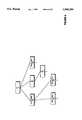
- FIG. 9illustrates the network of FIG. 8 after grouping physical devices into nodes.
- a method and apparatus for determining a connection path between two physical devices in a heterogeneous networkis described.
- specific detailsare set forth such as adjacency matrix contents, etc., in order to provided a thorough understanding of the present invention.
- known circuits, structures and techniqueshave not been shown in detail in order not to obscure the present invention.
- a network management toolconnects to the network and configures a virtual network.
- the network management tooldetermines: the capabilities of the physical devices on the network; the necessary configuration information for each physical device; and, the physical links between the physical devices (that is, the network management tool determines all the interconnections between all the nodes in the network).
- the network management toolfinds the virtual network's leaf nodes and all the nodes that interconnect them.
- the network management tooldetermines the availability of links between all the leaf nodes and the interconnect nodes. That is, the resource availability for the physical devices are checked and determined whether a path can be created between all the physical devices of the virtual network. Once the resource availability has been determined, the network management tool configures the virtual network nodes.
- a network management toolmodifies a presently existing network by adding a host to, or subtracting a host from, a virtual network.
- HostA terminal on a network.
- a hostis a computer.
- a hostwill have a unique address within a virtual network.
- VnetIn a network of physical devices, a vnet is a particular configuration of the physical devices that allows a group of hosts to communicate.
- NodeA logical or physical device in a network.
- a configuration nodeis a node that can be configured to allow communication between media coupled to that configuration node; for example, a hub, a group of ethernet switches or an ATM network.
- knowledge of the internal topology of a switched network, such as an ATM networkis not needed. Therefore, related physical switching devices can be grouped into one logical configuration node.
- Network Node ListThe list of nodes in the network.
- Leaf Node ListThe list of nodes connected to the hosts that are to be in one vnet.
- Interconnect Node ListThe list of nodes that connect the leaf nodes. The nodes in the interconnect node list must be configured in order for the vnet to be created or modified.
- Virtual Network Node Listthe list of all the nodes which will be configured in the construction or modification of the virtual network.
- Interconnection ListThe list of connections (links) between configuration nodes.
- FIG. 1illustrates a computer system 100 upon which an embodiment of the invention can be implemented.
- the computer system 100includes a bus 101, or other communications hardware and software, for communicating information, and a processor 109, coupled with the bus 101, is for processing information.
- the processor 109can be a single processor or a number of individual processors that can work together.
- the computer system 100further includes a memory 104.
- the memory 104can be random access memory (RAM), or some other dynamic storage device.
- the memory 104is coupled to the bus 101 and is for storing information and instructions to be executed by the processor 109.
- the memory 104also may be used for storing temporary variables or other intermediate information during the execution of instructions by the processor 109.
- the computer system 100also includes a ROM 106 (read only memory), and/or some other static storage device, coupled to the bus 101.
- the ROM 106is for storing static information such as instructions or data.
- the computer system 100can optionally include a data storage device 107, such as a magnetic disk, a digital tape system, or an optical disk and a corresponding disk drive.
- the data storage device 107can be coupled to the bus 101.
- the computer system 100can also include a display device 121 for displaying information to a user.
- the display device 121can be coupled to the bus 101.
- the display device 121can include a frame buffer, specialized graphics rendering devices, a cathode ray tube (CRT), and/or a flat panel display.
- the bus 101can include a separate bus for use by the display device 121 alone.
- An input device 122is typically coupled to the bus 101 for communicating information, such as command selections, to the processor 109 from a user.
- a cursor control 123such as a mouse, a trackball, a pen, a touch screen, a touch pad, a digital tablet, or cursor direction keys, for communicating direction information to the processor 109, and for controlling the cursor's movement on the display device 121.
- the cursor control 123typically has two degrees of freedom, a first axis (e.g., x) and a second axis (e.g., y), which allows the cursor control 123 to specify positions in a plane.
- the computer system 100is not limited to input devices with only two degrees of freedom.
- a hard copy device 124which may be used for printing instructions, data, or other information, on a medium such as paper, film, slides, or other types of media.
- a sound recording and/or playback device 125can optionally be coupled to the bus 101.
- the sound recording and/or playback device 125can include an audio digitizer coupled to a microphone for recording sounds.
- the sound recording and/or playback device 125may include speakers which are coupled to digital to analog (D/A) converter and an amplifier for playing back sounds.
- D/Adigital to analog
- a video input/output device 126can optionally be coupled to the bus 101.
- the video input/output device 126can be used to digitize video images from, for example, a television signal, a video cassette recorder, and/or a video camera.
- the video input/output device 126can include a scanner for scanning printed images.
- the video input/output device 126can generate a video signal for, for example, display by a television.
- the computer system 100can be part of a computer network (for example, a LAN) using an optional network connector 127, being coupled to the bus 101.
- a computer networkfor example, a LAN
- an entire networkcan then also be considered to be part of the computer system 100.
- An optional device 128can optionally be coupled to the bus 101.
- the optional device 128can include, for example, a PCMCIA card and a PCMCIA adapter.
- the optional device 128can further include an optional device such as modem or a wireless network connection.
- FIG. 2illustrated a network 200 having hosts, physical devices, and a network management tool 210.
- the network management tool 210includes an application that allows the network administrator to provide the network management tool 210 with a set of hosts (in this example, host A222, host B224 and host C226) that are to be part of one virtual network.
- the network management tool 210communicates with the physical devices in the network 200 to determine: the capabilities of the physical devices in the network 200 (for example, an ATM device requires configuration information different from a shared media device); the necessary configuration information for each physical device; and, the physical connection of the devices.
- the management tool 210attempts to determine at least one possible set of physical devices that will support the virtual network.
- the network management tool 210configures that set of physical devices to create the virtual network (vnet). Note the network management tool 210 saves the network administrator from having to attempt to configure the network 200. Without requiring further intervention by the network administrator, the network management tool 210 will configure the physical devices supporting the virtual network or will indicate that the virtual network cannot be created.
- Network 200includes the following hosts: host A 222, host B 224, host C 226, host F 262, host G 264, host H 266 an host I 286. Each host can be a computer such as computer system 100.
- Network 200includes the following physical devices: ethernet switch A 232, ethernet switch B 234, hub A 242, hub B 244, hub C 246 and ATM switch 250.
- An ethernet switchcan be, for example, model 28115 LattisSwitch, available from Bay Networks, Inc., of Santa Clara, Calif.
- a hubcan be, for example, System 5000, available from Bay Networks, Inc.
- An ATM switch 250can be, for example, model 10114, Lattis Cell, available from Bay Networks, Inc. Note that separate physical devices can be enclosed in one chassis yet still be considered separate physical devices.
- Host A 222, host B 224, and host C 226may be the computers used by the people of the finance department in a company.
- the network management tool 210would then, after performing the processes described below, create the virtual network 280.
- the virtual networkis created by identifying the physical devices that need to be configured, and then configuring those physical devices.
- ethernet switch B 234, ethernet switch A 232, hub B 244, and ATM switch 250(configured physical devices 270), would all be configured by the network management tool 210 to create the virtual network 280.
- hub A 242 and hub C 246would not be configured because the network management tool 210 would determine that no configuration of these physical devices was necessary.
- the network administratorwould have to determine which physical devices should be configured and then configure those physical devices. In a network the size of network 200, this may not be too time consuming (for example, the physical devices may be located in different building or even different cities). However, in a larger network, determining how to configure the physical devices in the network to achieve a virtual network can be difficult and time consuming.
- the network administratorneeds to have an up to date view of the network; must determine how to configure the physical devices on the network to achieve a virtual network; and must issue the commands to configure those physical devices.
- the networkincludes loops (i.e. multiple paths between two devices), the complexity of the problem increases. This introduces multiple solutions to the problem of creating the virtual network. The network administrator may not discover the best configuration of physical devices to create the virtual network.
- One embodiment of the present inventiondetermines the best configuration of physical devices even when loops are present in the network.
- FIG. 3illustrates one embodiment of a method of determining the physical connections in a network. This method could be implemented in an network management tool 210 executing on a computer system 100.
- a testis made to determine whether all the physical devices in the network have been processed. In one embodiment, this is performed by the network management tool 210 accessing a database.
- the databasecontains a list of all the physical devices in the network and all the physical interconnections between the physical devices. Such a database can be created by the network administrator.
- the informationincludes a topology which is obtained from an autotopology system.
- One such autotopology system, Optivityis available from Bay Networks, Inc., of Santa Clara, Calif.
- Such an autotopology systemdetermines all the physical devices on the network and their physical interconnections. In any case, what is important in step 310 is that the physical devices in the network and their interconnections are identified.
- step 320 through step 390create nodes representing one or more physical devices.
- Some physical devicescan be grouped into a single node where those physical devices can configure themselves to create a path between any two connections to the group. This reduces the complexity of the creation of a vnet because fewer nodes need be processed later on.
- a testis made to determine whether the physical device is an ethernet switch. If the physical device is an ethernet switch, then at step 330 all the ethernet switches physically connected to that ethernet switch are found. At step 340, an ethernet switch node is created from all the ethernet switches found connected in step 330. This effectively amalgamates all the ethernet switches, that are physically connected, into one node.
- the newly created nodeis added to a network node list.
- a test at step 360is performed to determine whether the physical device is a shared media hub such as a System 3000 available from Bay Networks, Inc. If the physical device is a shared media hub, then at step 365, the network management tool creates a node for the shared media hub. Next, at step 350, the new node is added to the network node list.
- a shared media hubsuch as a System 3000 available from Bay Networks, Inc.
- step 270determines whether the physical device is an ATM switch. If the physical device is an ATM switch, then at step 380, all the other ATM switches physically connected to that ATM switch are found. Next, at step 390, and ATM switch node is created from all the ATM switches connected to the ATM switch of step 370. This is analogous to step 340. Then, at step 350, the new node is added to the network node list.
- a token ring network physical devicecould be identified by a node. A token ring node would then be added to the network node list.
- step 395is executed.
- an adjacency matrixis created for the network node list.
- the adjacency matrixis created for each node in the network node list.
- the adjacency matrixincludes, for each node, the list of other nodes that are physically connected to that node. That is, the adjacency matrix identifies the physically connected peers for each node in the network. This adjacency matrix can then be used to determine the required virtual network.
- the adjacency matrixincludes weights.
- a weight of onerepresents no connection.
- a weight less than onerepresents a particular type of communications media/amount of bandwidth.
- lower weightsare given to faster communications links. Therefore, in one embodiment, when presented with multiple possible configurations for a virtual network, the network management tool 210 can compare the weights of the configurations to determine the best configuration. The best configuration would be the one with the lowest value.
- the best pathmay use physical devices experiencing the least load.
- This inventionis not limited to, for example, using weights of decreasing value. What is important is that some correlation between the physical characteristics of the physical devices of the network and some objective criteria required by the network administrator can be determined.
- FIG. 4illustrates one embodiment of a method of determining the path to connect the nodes of virtual network.
- the pathincludes a set of physical devices and the connections between the physical devices. This embodiment can be executed by network management tool 210 executing on computer system 100.
- This embodimentdetermines the best path by determining the smallest set of nodes needed to connect the host of the virtual network. Because each virtual network uses the smallest set of nodes the physical devices in the network are used to their fullest potential. This helps keep the number of physical devices required in the network to a minimum, thereby reducing the cost of the network. Also, because the smallest set of nodes is found, the configuration time is kept to a minimum. This allows a network administrator more time to experiment with different virtual networks.
- the best pathmay be determined using other criteria (e.g. fastest communications path, most available bandwidth path, most amount of resources available path).
- the nodes coupling to the hostsare added to the vnet node list.
- Each hostis connected to one node in the network.
- the leaf node listcan be generated when the network node list is created.
- step 420a test is made to determine whether all the leaf nodes have been processed in the vnet node list. If all the leaf nodes have not been processed, then step 430; is executed.
- a node from the vnet node listis assigned to be the current vnet node.
- step 440an adjacent node to the current vnet node is searched for. This is described in FIG. 5.
- a testis made to determine whether an adjacent node has been found. If an adjacent node is found, then, at step 455, the adjacent node is added to the interconnect node list. The necessary link is also recorded. If the adjacent node is already in the interconnect node list, and the corresponding link has been noted, then no further action is taken. If no adjacent node is found, then at step 460, an error is noted in the adjacency list. This indicates that the virtual network cannot be created given the present physical devices and interconnections of the network.
- the interconnect node listis merged into the vnet node list.
- the vnet node listrepresents the set of nodes needed to create the required virtual network, while the recorded links indicate how the vnet node list nodes are connected to form the vnet.
- FIG. 5illustrates one embodiment of a method of finding an adjacent node for a node.
- the method of FIG. 5is implemented in a subroutine that has an input a list of nodes.
- the input to this subroutineis the current vnet node, the vnet node list and the interconnection node list.
- a testis made to determine whether all the nodes in the node list have been tested.
- a testis made to determine whether the test node is in the adjacency list of the present node. In one embodiment of the present invention this is performed by addressing the adjacency matrix using the test node and the present node.
- a linkis recorded between the present node and the test node. This recording can be done in an interconnect node list.
- a return from the subroutineis made indicating that an adjacent node (the test node) has been found.
- step 530if the test node is not in the adjacency list of this leaf node, then the adjacency list of the test node is accessed.
- this subroutineis called for each of the nodes in the adjacency list of the test node.
- step 550a test is made to determine whether an adjacent node has been found. If an adjacent node has been found, then at step 560, the subroutine returns indicating that an adjacent node has been found. If an adjacent node has not been found, then step 510 is executed.
- FIG. 6illustrates one embodiment of a method for determining the resource availability of a network. That is, the physical devices used to create the virtual network must be able to support the links in the path of the virtual network.
- the method of FIG. 6can be performed by the network management tool 210 executing on computer system 100.
- a testis performed to determine whether all the links in the interconnection list have been processed. If not all the links have been processed, then at step 630, a test is made to determine whether there are resources available between the two nodes that form the link. In one embodiment of the present invention, this is done by accessing the database used in FIG. 3. The database indicates whether physical devices have sufficient resources to make a link.
- the first physical devicemight be a hub having a coaxial connection.
- a second physical devicemight be another hub having a coaxial connection. The two hubs would be physically connected via a coaxial cable.
- the test of step 630would then determine whether the coaxial cable is available for use for the virtual network.
- Step 620the exact link connection is recorded. However, if the resources are not available between the two nodes, then at step 640, a record is kept of a failed link interconnection. Step 610 through step 640 are executed for each link in the interconnection list. If there are any failed links then these links can be displayed for the network administrator. The failed links indicate that a particular connection between two physical devices is not available. The network administrator may then modify the network to allow the network to be configured to create the virtual network.
- a shared media hubis to be a configured physical device 370
- the resources within the hubmust be tested as well. For example in one type of shared media hub a finite number of ports may be interconnected on that particular hub. Therefore, although two physical devices may be physically connected by ports and those two physical devices may have that resource available, one of the two hubs may not be able to internally support a connection to one of the ports. Therefore, the link could not be made. This failure would then be recorded for the network administrator.
- each nodeis configured by the network management tool 210 using the link information from the connections list.
- the following pseudo codeillustrates one embodiment of a method for configuring the nodes given the vnet list.
- the network management tooldisplays an error message.
- the modification of an already existing vnetis performed using a method similar to the creation of the vnet.
- the modification methodwill be described in terms of a one host move or reassignment.
- FIG. 7illustrates a network upon which one embodiment of the present invention can operate.
- This networkincludes a number of hosts which are to be connected in a vnet. To create the vnet, the physical devices on the network need to be configured.
- the physical devices of this networkhave already been converted into nodes using the method of step 310 through step 390.
- no physical devicescan be grouped with other physical devices (as in step 340 and step 390). Lines between the nodes represent physical connections.
- the network of FIG. 7contains both configuration nodes and hosts. Hosts A B, C, D and E are to be included in one vnet.
- the networkincludes configuration nodes N1 710, N2 720, N3 780, N750, N5 740, N6 770, N7 730, N8 760 and N9 790.
- N1 710is physically connected to N2 720, N4 750 and N3 780.
- N2 720is connected to N1 710 and A.
- N3 780is connected to N9 790, N1 710 and B.
- N4 750is connected to N1 710, N5 740 and N6 770.
- N5 740is connected to N4 750, N7 730 and N8 760.
- N6 770is connected to N4 750 and C.
- N7 730is connected to D and N5 740.
- N8 760is connected to N5 740 and E.
- FIG. 3creates the adjacency matrix below.
- An "x"indicates an adjacency.
- step 410the leaf nodes N2 720, N3 780, N6 770, N7 730, and N8 760, are added to the vnet node list. Then step 420 through step 450 is repeated for each node in the vnet node list having the following results.
- step 610 through step 640are executed to ensure that the physical devices identified by each link in the interconnection list have the resources needed to create each link. Finally, the nodes in the vnet node list are configured.
- FIG. 8illustrates a network similar to the network of FIG. 7. However, the network of FIG. 8 includes physical devices that can be grouped into nodes.
- the networkincludes the following physical devices: ethernet switch5 820, ethernet switch1 880, ethernet switch 2 840, ethernet switch3 850 and ethernet switch4 860.
- the networkalso includes hosts A, B, C, D and E.
- N1 710is physically connected to ethernet switch 5 820, N4 750, N6 770 and ethernet switch 1 880.
- Ethernet switch 5 820is physically connected to N1 710, ethernet switch 2 840 and A.
- N4 750is physically connected to N1 710 and N6 770.
- Ethernet switch1 880is physically connected to N1 710 and B.
- Ethernet switch2 840is physically connected to ethernet switch5 820, ethernet switch3 850 and ethernet switch4 860.
- Ethernet switch3 850is physically connected to ethernet switch2 840 and D.
- Ethernet switch4 860is physically connected to ethernet switch2 840 and E.
- step 320After performing step 310 through step 390, the network of FIG. 8 is logically represented as the network of FIG. 9.
- step 320When step 320 is executed for ethernet switch 5 820, step 330 and step 340 are performed.
- Step 330causes ethernet switch2 840, ethernet switch3 850, and ethernet switch4 860 to be found.
- Step 340creates a node ethernet switch SN2 910.
- Ethernet switch SN2 910represents a node for these physical ethernet switches.
- ethernet switch1 880not physically connected with another ethernet switch, is grouped into a separate node ethernet switch SN1 900.
- Step 395then creates the following adjacency matrix.
- leaf nodesare added to the vnet node list, at step 410, and step 420 through step 450 are executed. The following results are achieved.
- the networkis configured as described above.
Landscapes
- Engineering & Computer Science (AREA)
- Computer Networks & Wireless Communication (AREA)
- Signal Processing (AREA)
- Data Exchanges In Wide-Area Networks (AREA)
Abstract
Description
______________________________________ create an empty list of configurations done. for (each vnet node) switch (get type of physical device) { case physical device.sub.-- type.sub.-- 1 : configure.sub.-- physical device.sub.-- type.sub.-- 1; case physical device.sub.-- type.sub.-- 2 : configure.sub.-- physical device.sub.-- type.sub.-- 2; . . . . } tag configuration as done } if (all configuration done) then exit algorithm else unconfigure the nodes ____________________________________________________________________________ find leaf node that host is part of if (leaf node already has this vnet in it) then check the node configuration to determine whether the host can be added or not if (OK) configure the node } else { follow the creation algorithm } ____________________________________________________________________________ Hosts A, B, C, D, E Lead Node List Empty Interconnect Node List Empty Vnet Nodes List Empty Interconnection List Empty ______________________________________
______________________________________ Hosts A, B, C, D, E Lead Node List N2, N3, N6, N7, N8 Interconnect Node List Empty Vnet Nodes List Empty Interconnection List Empty ______________________________________
______________________________________ N1 N2 N3 N4 N5 N6N7 N8 N9 710 720 780 750 740 770 730 760 790 ______________________________________ N1 x x x 710 N2 x 720N3 x x 780N4 x x x 750 N5 x x x 740 N6 x 770 N7 x 730 N8 x 760 N9 x 790 ______________________________________
______________________________________ =============== First vnet node IsN2 720 in the adjacency list ofN3 780,N6 770,N7 730 orN8 760? No Get adjacency list ofN2 720 --->N1 710 IsN1 710 in the adjacency list ofN3 780,N6 770,N7 730 orN8 760 Yes --->add N1 710 to the Interconnect Node List and record the link. Vnet Node List ##STR1## Interconnect Node List ##STR2## =============== Second vnet mode IsN3 780 in the adjacency list ofN2 720,N6 770,N7 730,N8 760 orN1 710 Yes complete, do no add anything Vnet Node List ##STR3## Interconnect Node List ##STR4## =============== Third vnet node IsN6 770 in the adjacency list ofN2 720,N3 780,N7 730,N8 760 orN1 710 No Get the adjacency list ofN6 770 ---->N4 750 IsN4 750 in the adjacency list ofN2 720,N3 780,N7 730,N8 760 orN1 710 Yes ----> addN4 750 to the interconnect Node List and record the link. Vnet Node List ##STR5## Interconnect Node List ##STR6## =============== Fourth vnet node IsN7 730 in the adjacency list ofN2 720,N3 780,N7 730,N8 760,N1 710 orN4 750 No Get the adjacency list ofN7 730 ---->N5 740 IsN5 740 in the adjacency list ofN2 720,N3 780,N7 730,N8 760,N1 710 orN4 750 Yes ----> addN5 740 to the interconnect Node List and record the link. Vnet Node List. ##STR7## Interconnect Node List ##STR8## =============== Fifth vnet node IsN8 760 in the adjacency list ofN2 720,N3 780,N7 730,N8 760,N1 710,N4 750 orN5 740 Yes complete, do not add anything. Vnet Node List ##STR9## Interconnect Node List ##STR10## ______________________________________
______________________________________ Hosts A, B, C, D, E LeadNode List N2 720,N3 780,N6 770,N7 730,N8 760 InterconnectNode List N5 740,N4 750,N1 710 Interconnection List N2 720 ->N1 710 N3 780 ->N1 710 N6 770 ->N4 750 N7 730 ->N5 740 N8 760 ->N5 740 N4 750 ->N1 710 N5 740 ->N4 750 VnetNodes List N1 710,N2 720,N3 780,N4 750,N5 740,N6 770,N7 760,N8 760 ______________________________________
______________________________________ N1 SN1N4 N6 SN2 710 900 750 770 910 ______________________________________ N1 x x 710 SN1 x 900N4 x x 750 N6 x 770 SN2 x 910 ______________________________________
______________________________________ Hosts : A, B, C, D, E Lead Node List :SN1 900,SN2 910,N6 770 Interconnect Node List : Empty Interconnection List : Empty =============== First vnet node Is SN1 900 in the adjacency list ofSN2 910 orN6 770? No Get adjacency list ofSN1 900 --->N1 710 IsN1 710 in the adjacency list ofSN2 910 orN6 770 Yes --->ad N1 710 to the Interconnect Node List and record the link. Vnet Node List ##STR11## Interconnect Node List ##STR12## =============== Second vnet node Is SN2 910 in the adjacency list ofSN1 900,N6 770 orN1 710? Yes. Complete do not add any nodes to the interconnect node list. =============== Third vnet node IsN6 770 in the adjacency list ofSN1 900,SN2 910 orN1 710? Yes. Complete do not add any nodes to the interconnect node list. The results are: Hosts : A, B, C, D, E Lead Node List :SN1 900,SN2 910,N6 770 Interconnect Node List :N1 710 Interconnection List : SN2 910 ->N1 710 N6 770 ->N1 710 SN1 900 ->N1 710 Add link counts to Interconnection List: Hosts : A, B, C, D, E Lead Node List :SN1 900,SN2 910,N6 770 Interconnect Node List :N1 710,N4 760 Link Counts Interconnection List : SN2 910 ->N1 710 1 N6 770 ->N1 710 1 SN1 990 ->N1 710 1 ______________________________________
Claims (31)
Priority Applications (1)
| Application Number | Priority Date | Filing Date | Title |
|---|---|---|---|
| US08/447,066US5802286A (en) | 1995-05-22 | 1995-05-22 | Method and apparatus for configuring a virtual network |
Applications Claiming Priority (1)
| Application Number | Priority Date | Filing Date | Title |
|---|---|---|---|
| US08/447,066US5802286A (en) | 1995-05-22 | 1995-05-22 | Method and apparatus for configuring a virtual network |
Publications (1)
| Publication Number | Publication Date |
|---|---|
| US5802286Atrue US5802286A (en) | 1998-09-01 |
Family
ID=23774879
Family Applications (1)
| Application Number | Title | Priority Date | Filing Date |
|---|---|---|---|
| US08/447,066Expired - LifetimeUS5802286A (en) | 1995-05-22 | 1995-05-22 | Method and apparatus for configuring a virtual network |
Country Status (1)
| Country | Link |
|---|---|
| US (1) | US5802286A (en) |
Cited By (47)
| Publication number | Priority date | Publication date | Assignee | Title |
|---|---|---|---|---|
| US6049828A (en)* | 1990-09-17 | 2000-04-11 | Cabletron Systems, Inc. | Method and apparatus for monitoring the status of non-pollable devices in a computer network |
| US6098067A (en)* | 1997-05-02 | 2000-08-01 | Kabushiki Kaisha Toshiba | Remote computer management system |
| US6167568A (en)* | 1998-06-30 | 2000-12-26 | Sun Microsystems, Inc. | Method and apparatus for implementing electronic software distribution |
| US20020002704A1 (en)* | 1995-03-10 | 2002-01-03 | Davis Michael L. | Automatic software installation on heterogeneous networked computer systems |
| US20020004902A1 (en)* | 2000-07-07 | 2002-01-10 | Eng-Whatt Toh | Secure and reliable document delivery |
| US20020013840A1 (en)* | 2000-07-21 | 2002-01-31 | John Border | Network management of a performance enhancing proxy architecture |
| US20020019932A1 (en)* | 1999-06-10 | 2002-02-14 | Eng-Whatt Toh | Cryptographically secure network |
| US20020048372A1 (en)* | 2000-10-19 | 2002-04-25 | Eng-Whatt Toh | Universal signature object for digital data |
| US6405270B1 (en) | 1999-09-08 | 2002-06-11 | Lsi Logic Corporation | Method and apparatus for increasing data rates between nodes of a serial bus |
| US20020083159A1 (en)* | 2000-11-06 | 2002-06-27 | Ward Julie A. | Designing interconnect fabrics |
| US20020101998A1 (en)* | 1999-06-10 | 2002-08-01 | Chee-Hong Wong | Fast escrow delivery |
| US6449251B1 (en) | 1999-04-02 | 2002-09-10 | Nortel Networks Limited | Packet mapper for dynamic data packet prioritization |
| EP1017246A3 (en)* | 1998-11-20 | 2003-01-08 | Crosskeys Systems Corporation | Calculation of resource availability using degradation factors |
| US6519634B1 (en)* | 1998-10-13 | 2003-02-11 | Samsung Electronics Co., Ltd. | Method of generating IEEE 1394 virtual network in which a virtual network controller is connected to generate self ID packets as virtual node ID |
| US6519660B1 (en)* | 1999-09-28 | 2003-02-11 | International Business Machines Corporation | Method, system and program products for determining I/O configuration entropy |
| US20030055932A1 (en)* | 2001-09-19 | 2003-03-20 | Dell Products L.P. | System and method for configuring a storage area network |
| US20030065758A1 (en)* | 2001-09-28 | 2003-04-03 | O'sullivan Michael Justin | Module-building method for designing interconnect fabrics |
| US20030105844A1 (en)* | 1999-06-08 | 2003-06-05 | Nec Corporation | Topology information automatic configuration method and its topology information automatic configuration system |
| US20030103464A1 (en)* | 2001-11-30 | 2003-06-05 | Palm Inc. | Network connectivity system and method |
| US20030140128A1 (en)* | 2002-01-18 | 2003-07-24 | Dell Products L.P. | System and method for validating a network |
| US20030145294A1 (en)* | 2002-01-25 | 2003-07-31 | Ward Julie Ann | Verifying interconnect fabric designs |
| US20030163807A1 (en)* | 2002-02-27 | 2003-08-28 | International Business Machines Corporation | Weighted selection of target systems for distributed software installation |
| US20030191845A1 (en)* | 2002-04-03 | 2003-10-09 | Hinds John Sherman | Method, apparatus and system for establishing communications between communications devices |
| US6662221B1 (en)* | 1999-04-12 | 2003-12-09 | Lucent Technologies Inc. | Integrated network and service management with automated flow through configuration and provisioning of virtual private networks |
| US6701358B1 (en)* | 1999-04-02 | 2004-03-02 | Nortel Networks Limited | Bulk configuring a virtual private network |
| US20040088437A1 (en)* | 2002-10-30 | 2004-05-06 | Brocade Communications Systems, Inc. | Network merge testing |
| US20040090439A1 (en)* | 2002-11-07 | 2004-05-13 | Holger Dillner | Recognition and interpretation of graphical and diagrammatic representations |
| US6747957B1 (en)* | 2000-04-28 | 2004-06-08 | Cisco Technology, Inc. | Network availability monitor |
| US6757286B1 (en)* | 1997-03-24 | 2004-06-29 | Alcatel | Self-configuring communication network |
| US6765591B2 (en) | 1999-04-02 | 2004-07-20 | Nortel Networks Limited | Managing a virtual private network |
| US20040243705A1 (en)* | 2003-05-30 | 2004-12-02 | Netravali Arun N. | Methods and apparatus for virtual network configuration |
| US20050022183A1 (en)* | 1999-04-02 | 2005-01-27 | Poisson Matthew W. | Virtual private network manager GUI with links for use in configuring a virtual private network |
| US20050071482A1 (en)* | 2003-09-30 | 2005-03-31 | Gopisetty Sandeep K. | System and method for generating perspectives of a SAN topology |
| US20060020944A1 (en)* | 1999-09-28 | 2006-01-26 | International Business Machines Corporation | Method, system and program products for managing logical processors of a computing environment |
| US7000014B2 (en) | 1999-04-02 | 2006-02-14 | Nortel Networks Limited | Monitoring a virtual private network |
| US20060182035A1 (en)* | 2005-02-14 | 2006-08-17 | Jean-Philippe Vasseur | Technique for efficient load balancing of TE-LSPs |
| US20060182082A1 (en)* | 2005-02-11 | 2006-08-17 | Wakumoto Shaun K | Switching mesh with user-configurable paths |
| US20060268740A1 (en)* | 2005-05-24 | 2006-11-30 | Eric Rosenberg | Method for building virtual private networks using routers |
| US7171000B1 (en) | 1999-06-10 | 2007-01-30 | Message Secure Corp. | Simplified addressing for private communications |
| US20070028147A1 (en)* | 2002-07-30 | 2007-02-01 | Cisco Technology, Inc. | Method and apparatus for outage measurement |
| US20070033252A1 (en)* | 2000-03-30 | 2007-02-08 | Combest Ricky F | Dynamic virtual network and method |
| US7251728B2 (en) | 2000-07-07 | 2007-07-31 | Message Secure Corporation | Secure and reliable document delivery using routing lists |
| WO2007037867A3 (en)* | 2005-09-15 | 2007-10-04 | Tp Lab Inc | Method to dynamically create a virtual network |
| US20080219277A1 (en)* | 2007-03-06 | 2008-09-11 | Cisco Technology, Inc | Modelling service flows in dynamic access domains |
| US7743122B1 (en)* | 2007-11-07 | 2010-06-22 | The United States Of America As Represented By The Director Of The National Security Agency | Method of reliably communicating via computer network |
| US20100262708A1 (en)* | 2009-04-08 | 2010-10-14 | Nokia Corporation | Method and apparatus for delivery of scalable media data |
| US20150172106A1 (en)* | 2008-03-17 | 2015-06-18 | Microsoft Technology Licensing, Llc | Virtualization of groups of devices |
Citations (10)
| Publication number | Priority date | Publication date | Assignee | Title |
|---|---|---|---|---|
| US5142624A (en)* | 1989-11-08 | 1992-08-25 | Softworx, Inc. | Virtual network for personal computers |
| US5276440A (en)* | 1989-02-16 | 1994-01-04 | International Business Machines Corporation | Network device information exchange |
| US5307465A (en)* | 1990-03-29 | 1994-04-26 | Nec Corporation | System for updating network topology based on configuration obtained from subset configuration composition matrix and switching node connection matrix for the subset configuration |
| US5430730A (en)* | 1993-09-14 | 1995-07-04 | Rolm Company | Method for building a sub-network in a distributed voice messaging system |
| US5497460A (en)* | 1994-06-20 | 1996-03-05 | International Business Machines Corporation | System and method for determining network connectivity |
| US5517622A (en)* | 1991-04-11 | 1996-05-14 | Galileo International Partnership | Method and apparatus for pacing communications in a distributed heterogeneous network |
| US5583862A (en)* | 1995-03-28 | 1996-12-10 | Bay Networks, Inc. | Method and apparatus for routing for virtual networks |
| US5600644A (en)* | 1995-03-10 | 1997-02-04 | At&T | Method and apparatus for interconnecting LANs |
| US5633869A (en)* | 1992-09-14 | 1997-05-27 | Network Equipment Technologies, Inc. | Virtual network using asynchronous transfer mode |
| US5684959A (en)* | 1995-04-19 | 1997-11-04 | Hewlett-Packard Company | Method for determining topology of a network |
- 1995
- 1995-05-22USUS08/447,066patent/US5802286A/ennot_activeExpired - Lifetime
Patent Citations (10)
| Publication number | Priority date | Publication date | Assignee | Title |
|---|---|---|---|---|
| US5276440A (en)* | 1989-02-16 | 1994-01-04 | International Business Machines Corporation | Network device information exchange |
| US5142624A (en)* | 1989-11-08 | 1992-08-25 | Softworx, Inc. | Virtual network for personal computers |
| US5307465A (en)* | 1990-03-29 | 1994-04-26 | Nec Corporation | System for updating network topology based on configuration obtained from subset configuration composition matrix and switching node connection matrix for the subset configuration |
| US5517622A (en)* | 1991-04-11 | 1996-05-14 | Galileo International Partnership | Method and apparatus for pacing communications in a distributed heterogeneous network |
| US5633869A (en)* | 1992-09-14 | 1997-05-27 | Network Equipment Technologies, Inc. | Virtual network using asynchronous transfer mode |
| US5430730A (en)* | 1993-09-14 | 1995-07-04 | Rolm Company | Method for building a sub-network in a distributed voice messaging system |
| US5497460A (en)* | 1994-06-20 | 1996-03-05 | International Business Machines Corporation | System and method for determining network connectivity |
| US5600644A (en)* | 1995-03-10 | 1997-02-04 | At&T | Method and apparatus for interconnecting LANs |
| US5583862A (en)* | 1995-03-28 | 1996-12-10 | Bay Networks, Inc. | Method and apparatus for routing for virtual networks |
| US5684959A (en)* | 1995-04-19 | 1997-11-04 | Hewlett-Packard Company | Method for determining topology of a network |
Non-Patent Citations (6)
| Title |
|---|
| Ferrari et al., "Resource Patitioning for Real-Time Communication", Global Data Networking Symposium, IEEE, 1993, pp. 128-135. |
| Ferrari et al., Resource Patitioning for Real Time Communication , Global Data Networking Symposium, IEEE, 1993, pp. 128 135.* |
| Landegem et al., "Managing a Connectionless Virtual Overlay Network on Top an ATM Network", Communications, 1991 IEEE International Conference, IEEE, 1991, pp. 988-992. |
| Landegem et al., Managing a Connectionless Virtual Overlay Network on Top an ATM Network , Communications, 1991 IEEE International Conference, IEEE, 1991, pp. 988 992.* |
| Weber et al., "An Optimization Method for Virtual Private Network Design", Private Switching Systems & Network, IEEE, 1992, pp. 31-36. |
| Weber et al., An Optimization Method for Virtual Private Network Design , Private Switching Systems & Network, IEEE, 1992, pp. 31 36.* |
Cited By (75)
| Publication number | Priority date | Publication date | Assignee | Title |
|---|---|---|---|---|
| US6049828A (en)* | 1990-09-17 | 2000-04-11 | Cabletron Systems, Inc. | Method and apparatus for monitoring the status of non-pollable devices in a computer network |
| US20020002704A1 (en)* | 1995-03-10 | 2002-01-03 | Davis Michael L. | Automatic software installation on heterogeneous networked computer systems |
| US7124409B2 (en)* | 1995-03-10 | 2006-10-17 | Microsoft Corporation | Automatic software installation on heterogeneous networked computer systems |
| US6757286B1 (en)* | 1997-03-24 | 2004-06-29 | Alcatel | Self-configuring communication network |
| US6098067A (en)* | 1997-05-02 | 2000-08-01 | Kabushiki Kaisha Toshiba | Remote computer management system |
| US6167568A (en)* | 1998-06-30 | 2000-12-26 | Sun Microsystems, Inc. | Method and apparatus for implementing electronic software distribution |
| US6519634B1 (en)* | 1998-10-13 | 2003-02-11 | Samsung Electronics Co., Ltd. | Method of generating IEEE 1394 virtual network in which a virtual network controller is connected to generate self ID packets as virtual node ID |
| EP1017246A3 (en)* | 1998-11-20 | 2003-01-08 | Crosskeys Systems Corporation | Calculation of resource availability using degradation factors |
| US7831689B2 (en) | 1999-04-02 | 2010-11-09 | Nortel Networks Corporation | Virtual private network manager GUI with links for use in configuring a virtual private network |
| US20050022183A1 (en)* | 1999-04-02 | 2005-01-27 | Poisson Matthew W. | Virtual private network manager GUI with links for use in configuring a virtual private network |
| US6449251B1 (en) | 1999-04-02 | 2002-09-10 | Nortel Networks Limited | Packet mapper for dynamic data packet prioritization |
| US7000014B2 (en) | 1999-04-02 | 2006-02-14 | Nortel Networks Limited | Monitoring a virtual private network |
| US6765591B2 (en) | 1999-04-02 | 2004-07-20 | Nortel Networks Limited | Managing a virtual private network |
| US20040199624A1 (en)* | 1999-04-02 | 2004-10-07 | Poisson Matthew W. | Managing a virtual private network |
| US6701358B1 (en)* | 1999-04-02 | 2004-03-02 | Nortel Networks Limited | Bulk configuring a virtual private network |
| US6662221B1 (en)* | 1999-04-12 | 2003-12-09 | Lucent Technologies Inc. | Integrated network and service management with automated flow through configuration and provisioning of virtual private networks |
| US20030105844A1 (en)* | 1999-06-08 | 2003-06-05 | Nec Corporation | Topology information automatic configuration method and its topology information automatic configuration system |
| US7185072B2 (en)* | 1999-06-08 | 2007-02-27 | Nec Corporation | Topology information automatic configuration method and its topology information automatic configuration system |
| US7171000B1 (en) | 1999-06-10 | 2007-01-30 | Message Secure Corp. | Simplified addressing for private communications |
| US20020019932A1 (en)* | 1999-06-10 | 2002-02-14 | Eng-Whatt Toh | Cryptographically secure network |
| US20020101998A1 (en)* | 1999-06-10 | 2002-08-01 | Chee-Hong Wong | Fast escrow delivery |
| US6405270B1 (en) | 1999-09-08 | 2002-06-11 | Lsi Logic Corporation | Method and apparatus for increasing data rates between nodes of a serial bus |
| US8458714B2 (en) | 1999-09-28 | 2013-06-04 | International Business Machines Corporation | Method, system and program products for managing logical processors of a computing environment |
| US6519660B1 (en)* | 1999-09-28 | 2003-02-11 | International Business Machines Corporation | Method, system and program products for determining I/O configuration entropy |
| US20060020944A1 (en)* | 1999-09-28 | 2006-01-26 | International Business Machines Corporation | Method, system and program products for managing logical processors of a computing environment |
| US20070033252A1 (en)* | 2000-03-30 | 2007-02-08 | Combest Ricky F | Dynamic virtual network and method |
| US6747957B1 (en)* | 2000-04-28 | 2004-06-08 | Cisco Technology, Inc. | Network availability monitor |
| US7251728B2 (en) | 2000-07-07 | 2007-07-31 | Message Secure Corporation | Secure and reliable document delivery using routing lists |
| US6988199B2 (en) | 2000-07-07 | 2006-01-17 | Message Secure | Secure and reliable document delivery |
| US20020004902A1 (en)* | 2000-07-07 | 2002-01-10 | Eng-Whatt Toh | Secure and reliable document delivery |
| EP1175042A3 (en)* | 2000-07-21 | 2003-08-13 | Hughes Electronics Corporation | Network management of a performance enhancing proxy architecture |
| US20020013840A1 (en)* | 2000-07-21 | 2002-01-31 | John Border | Network management of a performance enhancing proxy architecture |
| US20020048372A1 (en)* | 2000-10-19 | 2002-04-25 | Eng-Whatt Toh | Universal signature object for digital data |
| US7076537B2 (en)* | 2000-11-06 | 2006-07-11 | Hewlett-Packard Development Company, L.P. | Designing interconnect fabrics |
| US20020083159A1 (en)* | 2000-11-06 | 2002-06-27 | Ward Julie A. | Designing interconnect fabrics |
| US20080065748A1 (en)* | 2001-09-19 | 2008-03-13 | Dell Products L.P. | System and Method for Configuring a Storage Area Network |
| US7603446B2 (en) | 2001-09-19 | 2009-10-13 | Dell Products L.P. | System and method for configuring a storage area network |
| US20030055932A1 (en)* | 2001-09-19 | 2003-03-20 | Dell Products L.P. | System and method for configuring a storage area network |
| US7502839B2 (en)* | 2001-09-28 | 2009-03-10 | Hewlett-Packard Development Company, L.P. | Module-building method for designing interconnect fabrics |
| US20030065758A1 (en)* | 2001-09-28 | 2003-04-03 | O'sullivan Michael Justin | Module-building method for designing interconnect fabrics |
| US20030103464A1 (en)* | 2001-11-30 | 2003-06-05 | Palm Inc. | Network connectivity system and method |
| US7072326B2 (en) | 2001-11-30 | 2006-07-04 | Palm, Inc. | Network connectivity system and method |
| US20070019602A1 (en)* | 2001-11-30 | 2007-01-25 | Palm, Inc | Network connectivity system and method |
| US20030140128A1 (en)* | 2002-01-18 | 2003-07-24 | Dell Products L.P. | System and method for validating a network |
| US20030145294A1 (en)* | 2002-01-25 | 2003-07-31 | Ward Julie Ann | Verifying interconnect fabric designs |
| US7308494B1 (en)* | 2002-01-25 | 2007-12-11 | Hewlett-Packard Development Company, L.P. | Reprovisioning technique for an interconnect fabric design |
| US20030163807A1 (en)* | 2002-02-27 | 2003-08-28 | International Business Machines Corporation | Weighted selection of target systems for distributed software installation |
| US20030191845A1 (en)* | 2002-04-03 | 2003-10-09 | Hinds John Sherman | Method, apparatus and system for establishing communications between communications devices |
| US7523355B2 (en) | 2002-07-30 | 2009-04-21 | Cisco Technology, Inc. | Method and apparatus for outage measurement |
| US20070028147A1 (en)* | 2002-07-30 | 2007-02-01 | Cisco Technology, Inc. | Method and apparatus for outage measurement |
| US8055731B2 (en)* | 2002-10-30 | 2011-11-08 | Brocade Communication Systems, Inc. | Network merge testing |
| US20040088437A1 (en)* | 2002-10-30 | 2004-05-06 | Brocade Communications Systems, Inc. | Network merge testing |
| US20040090439A1 (en)* | 2002-11-07 | 2004-05-13 | Holger Dillner | Recognition and interpretation of graphical and diagrammatic representations |
| US7966385B2 (en)* | 2003-05-30 | 2011-06-21 | Alcatel-Lucent Usa Inc. | Methods and apparatus for virtual network configuration |
| US20040243705A1 (en)* | 2003-05-30 | 2004-12-02 | Netravali Arun N. | Methods and apparatus for virtual network configuration |
| US8069415B2 (en)* | 2003-09-30 | 2011-11-29 | International Business Machines Corporation | System and method for generating perspectives of a SAN topology |
| US20050071482A1 (en)* | 2003-09-30 | 2005-03-31 | Gopisetty Sandeep K. | System and method for generating perspectives of a SAN topology |
| US20060182082A1 (en)* | 2005-02-11 | 2006-08-17 | Wakumoto Shaun K | Switching mesh with user-configurable paths |
| US9497109B2 (en)* | 2005-02-11 | 2016-11-15 | Hewlett Packard Enterprise Development Lp | Switching mesh with user-configurable paths |
| US20060182035A1 (en)* | 2005-02-14 | 2006-08-17 | Jean-Philippe Vasseur | Technique for efficient load balancing of TE-LSPs |
| US9306831B2 (en)* | 2005-02-14 | 2016-04-05 | Cisco Technology, Inc. | Technique for efficient load balancing of TE-LSPs |
| US7583617B2 (en)* | 2005-05-24 | 2009-09-01 | At&T Corp. | Method for building virtual private networks using routers |
| US20060268740A1 (en)* | 2005-05-24 | 2006-11-30 | Eric Rosenberg | Method for building virtual private networks using routers |
| US20070294377A1 (en)* | 2005-09-15 | 2007-12-20 | Tp Lab | Method to dynamically create a virtual network |
| US20100208619A1 (en)* | 2005-09-15 | 2010-08-19 | Tp Lab, Inc. | Method to Dynamically Create a Virtual Network |
| US7986638B2 (en)* | 2005-09-15 | 2011-07-26 | Chi Fai Ho | Method to dynamically create a virtual network |
| WO2007037867A3 (en)* | 2005-09-15 | 2007-10-04 | Tp Lab Inc | Method to dynamically create a virtual network |
| US7733802B2 (en)* | 2005-09-15 | 2010-06-08 | Tp Lab, Inc. | Method to dynamically create a virtual network |
| US20080219277A1 (en)* | 2007-03-06 | 2008-09-11 | Cisco Technology, Inc | Modelling service flows in dynamic access domains |
| US8040820B2 (en)* | 2007-03-06 | 2011-10-18 | Cisco Technology, Inc. | Modelling service flows in dynamic access domains |
| US7743122B1 (en)* | 2007-11-07 | 2010-06-22 | The United States Of America As Represented By The Director Of The National Security Agency | Method of reliably communicating via computer network |
| US20150172106A1 (en)* | 2008-03-17 | 2015-06-18 | Microsoft Technology Licensing, Llc | Virtualization of groups of devices |
| CN102388609A (en)* | 2009-04-08 | 2012-03-21 | 诺基亚公司 | Method and apparatus for delivery of scalable media data |
| US20100262708A1 (en)* | 2009-04-08 | 2010-10-14 | Nokia Corporation | Method and apparatus for delivery of scalable media data |
| CN102388609B (en)* | 2009-04-08 | 2014-06-18 | 诺基亚公司 | Method and apparatus for delivering scalable media data |
Similar Documents
| Publication | Publication Date | Title |
|---|---|---|
| US5802286A (en) | Method and apparatus for configuring a virtual network | |
| US8412508B2 (en) | Creation and use of virtual device drivers on a serial bus | |
| EP1275050B1 (en) | Programmatic masking of storage units | |
| US6175866B1 (en) | Method and system for generating unsupported network monitoring objects | |
| US6295557B1 (en) | Apparatus for simulating internet traffic | |
| US6539415B1 (en) | Method and apparatus for the allocation of audio/video tasks in a network system | |
| US20020146002A1 (en) | Network administration apparatus, network administrating program, network administrating method and computer network system | |
| US5862377A (en) | Technique for sharing information between applications | |
| US6925492B2 (en) | Method and apparatus for automatic configuration of a cluster of computers | |
| US6643714B1 (en) | Modification and use of configuration memory used during operation of a serial bus | |
| US6829225B2 (en) | Method for computing speed map for IEEE-1394 network | |
| US6671768B1 (en) | System and method for providing dynamic configuration ROM using double image buffers for use with serial bus devices | |
| KR19990029323A (en) | Application program interface, how to implement it, and computer program products | |
| JPH07117933B2 (en) | Automatic configuration control device and method | |
| US20080281954A1 (en) | Capability requirements for group membership | |
| JP2004213533A (en) | Screen receiving device, screen distributing device, screen information transmitting / receiving system, screen receiving method, screen distributing method and program thereof | |
| JPS6059616B2 (en) | Network address management method | |
| CN100466585C (en) | Method and apparatus for implementing leaf node proxy in network | |
| JP2000322354A (en) | Device and method for managing network and computer readable storage medium with method stored therein | |
| EP3962036A1 (en) | Address generation | |
| US6757773B1 (en) | System and method for determining support capability of a device coupled to a bus system | |
| US7685303B2 (en) | Object-oriented discovery framework | |
| US20060195586A1 (en) | Sessions and terminals configured for binding in an extensible manner | |
| US7251248B2 (en) | Connection device | |
| US8549221B2 (en) | RAID management apparatus, RAID management method, and computer product |
Legal Events
| Date | Code | Title | Description |
|---|---|---|---|
| AS | Assignment | Owner name:SYNOPTICS COMMUNICATIONS INC., CALIFORNIA Free format text:ASSIGNMENT OF ASSIGNORS INTEREST;ASSIGNORS:DERE, JUDY Y.;LEONG, LEON Y.K.;SIMONE, DANIEL A.;AND OTHERS;REEL/FRAME:007512/0588 Effective date:19950518 | |
| AS | Assignment | Owner name:BAY NETWORKS, INC., CALIFORNIA Free format text:CHANGE OF NAME;ASSIGNOR:SYNOPTICS COMMUNICATIONS, INC.;REEL/FRAME:009281/0291 Effective date:19950112 | |
| STCF | Information on status: patent grant | Free format text:PATENTED CASE | |
| AS | Assignment | Owner name:NORTEL NETWORKS NA INC., CALIFORNIA Free format text:CHANGE OF NAME;ASSIGNOR:BAY NETWORKS, INC.;REEL/FRAME:010461/0283 Effective date:19990430 | |
| AS | Assignment | Owner name:NORTEL NETWORKS CORPORATION, CANADA Free format text:ASSIGNMENT OF ASSIGNORS INTEREST;ASSIGNOR:NORTEL NETWORKS NA INC.;REEL/FRAME:010547/0891 Effective date:19991229 | |
| AS | Assignment | Owner name:NORTEL NETWORKS LIMITED, CANADA Free format text:CHANGE OF NAME;ASSIGNOR:NORTEL NETWORKS CORPORATION;REEL/FRAME:011195/0706 Effective date:20000830 Owner name:NORTEL NETWORKS LIMITED,CANADA Free format text:CHANGE OF NAME;ASSIGNOR:NORTEL NETWORKS CORPORATION;REEL/FRAME:011195/0706 Effective date:20000830 | |
| FEPP | Fee payment procedure | Free format text:PAYOR NUMBER ASSIGNED (ORIGINAL EVENT CODE: ASPN); ENTITY STATUS OF PATENT OWNER: LARGE ENTITY | |
| FPAY | Fee payment | Year of fee payment:4 | |
| FPAY | Fee payment | Year of fee payment:8 | |
| FPAY | Fee payment | Year of fee payment:12 | |
| AS | Assignment | Owner name:ROCKSTAR BIDCO, LP, NEW YORK Free format text:ASSIGNMENT OF ASSIGNORS INTEREST;ASSIGNOR:NORTEL NETWORKS LIMITED;REEL/FRAME:027164/0356 Effective date:20110729 | |
| AS | Assignment | Owner name:ROCKSTAR CONSORTIUM US LP, TEXAS Free format text:ASSIGNMENT OF ASSIGNORS INTEREST;ASSIGNOR:ROCKSTAR BIDCO, LP;REEL/FRAME:032170/0591 Effective date:20120509 | |
| AS | Assignment | Owner name:BOCKSTAR TECHNOLOGIES LLC, DELAWARE Free format text:ASSIGNMENT OF ASSIGNORS INTEREST;ASSIGNOR:ROCKSTAR CONSORTIUM US LP;REEL/FRAME:032399/0116 Effective date:20131113 | |
| AS | Assignment | Owner name:RPX CLEARINGHOUSE LLC, CALIFORNIA Free format text:ASSIGNMENT OF ASSIGNORS INTEREST;ASSIGNORS:ROCKSTAR CONSORTIUM US LP;ROCKSTAR CONSORTIUM LLC;BOCKSTAR TECHNOLOGIES LLC;AND OTHERS;REEL/FRAME:034924/0779 Effective date:20150128 |