US5802086A - Single cavity solid state laser with intracavity optical frequency mixing - Google Patents
Single cavity solid state laser with intracavity optical frequency mixingDownload PDFInfo
- Publication number
- US5802086A US5802086AUS08/593,094US59309496AUS5802086AUS 5802086 AUS5802086 AUS 5802086AUS 59309496 AUS59309496 AUS 59309496AUS 5802086 AUS5802086 AUS 5802086A
- Authority
- US
- United States
- Prior art keywords
- solid state
- gain material
- wavelength
- crystal
- gain
- Prior art date
- Legal status (The legal status is an assumption and is not a legal conclusion. Google has not performed a legal analysis and makes no representation as to the accuracy of the status listed.)
- Expired - Lifetime
Links
- 230000003287optical effectEffects0.000titleclaimsabstractdescription77
- 239000007787solidSubstances0.000titleclaimsdescription106
- 239000000463materialSubstances0.000claimsabstractdescription228
- 239000013078crystalSubstances0.000claimsabstractdescription117
- 230000005855radiationEffects0.000claimsabstractdescription84
- 230000007704transitionEffects0.000claimsabstractdescription57
- 229910017502Nd:YVO4Inorganic materials0.000claimsabstractdescription18
- 239000002131composite materialSubstances0.000claimsabstractdescription17
- 230000010287polarizationEffects0.000claimsdescription38
- 238000005086pumpingMethods0.000claimsdescription32
- 238000000034methodMethods0.000claimsdescription18
- 229910052761rare earth metalInorganic materials0.000claimsdescription15
- 229910052779NeodymiumInorganic materials0.000claimsdescription12
- 238000006243chemical reactionMethods0.000claimsdescription12
- QEFYFXOXNSNQGX-UHFFFAOYSA-Nneodymium atomChemical compound[Nd]QEFYFXOXNSNQGX-UHFFFAOYSA-N0.000claimsdescription10
- 239000000203mixtureSubstances0.000claimsdescription7
- 230000009977dual effectEffects0.000description22
- 238000002310reflectometryMethods0.000description21
- BJQHLKABXJIVAM-UHFFFAOYSA-Nbis(2-ethylhexyl) phthalateChemical compoundCCCCC(CC)COC(=O)C1=CC=CC=C1C(=O)OCC(CC)CCCCBJQHLKABXJIVAM-UHFFFAOYSA-N0.000description14
- 238000010586diagramMethods0.000description12
- 238000010521absorption reactionMethods0.000description11
- 150000002500ionsChemical class0.000description9
- 230000008569processEffects0.000description8
- 230000008901benefitEffects0.000description6
- 239000000835fiberSubstances0.000description6
- 230000006870functionEffects0.000description6
- 230000005540biological transmissionEffects0.000description5
- 239000004065semiconductorSubstances0.000description5
- RIUWBIIVUYSTCN-UHFFFAOYSA-Ntrilithium borateChemical compound[Li+].[Li+].[Li+].[O-]B([O-])[O-]RIUWBIIVUYSTCN-UHFFFAOYSA-N0.000description5
- MDPILPRLPQYEEN-UHFFFAOYSA-Naluminium arsenideChemical compound[As]#[Al]MDPILPRLPQYEEN-UHFFFAOYSA-N0.000description4
- 238000000576coating methodMethods0.000description4
- 125000006850spacer groupChemical group0.000description4
- 229910009372YVO4Inorganic materials0.000description3
- 239000011149active materialSubstances0.000description3
- 238000003491arrayMethods0.000description3
- 230000001427coherent effectEffects0.000description3
- 230000008878couplingEffects0.000description3
- 238000010168coupling processMethods0.000description3
- 238000005859coupling reactionMethods0.000description3
- 238000005516engineering processMethods0.000description3
- 238000012986modificationMethods0.000description3
- 230000004048modificationEffects0.000description3
- -1neodymium ionsChemical class0.000description3
- 239000013307optical fiberSubstances0.000description3
- WYOHGPUPVHHUGO-UHFFFAOYSA-Kpotassium;oxygen(2-);titanium(4+);phosphateChemical compound[O-2].[K+].[Ti+4].[O-]P([O-])([O-])=OWYOHGPUPVHHUGO-UHFFFAOYSA-K0.000description3
- 239000000758substrateSubstances0.000description3
- 230000009471actionEffects0.000description2
- 230000001419dependent effectEffects0.000description2
- 238000009826distributionMethods0.000description2
- 239000011521glassSubstances0.000description2
- JRLGRXFRLJTQTF-UHFFFAOYSA-Jlithium neodymium(3+) [oxido-[oxido(phosphonooxy)phosphoryl]oxyphosphoryl] phosphateChemical compound[O-]P([O-])(=O)OP(=O)([O-])OP(=O)([O-])OP(=O)(O)O.[Nd+3].[Li+]JRLGRXFRLJTQTF-UHFFFAOYSA-J0.000description2
- IBHUXEUKLQACLH-UHFFFAOYSA-Aneodymium(3+) [oxido-[oxido-[oxido(phosphonatooxy)phosphoryl]oxyphosphoryl]oxyphosphoryl] phosphateChemical compound[Nd+3].[Nd+3].[Nd+3].[Nd+3].[Nd+3].[Nd+3].[Nd+3].[O-]P([O-])(=O)OP([O-])(=O)OP([O-])(=O)OP([O-])(=O)OP([O-])([O-])=O.[O-]P([O-])(=O)OP([O-])(=O)OP([O-])(=O)OP([O-])(=O)OP([O-])([O-])=O.[O-]P([O-])(=O)OP([O-])(=O)OP([O-])(=O)OP([O-])(=O)OP([O-])([O-])=OIBHUXEUKLQACLH-UHFFFAOYSA-A0.000description2
- 239000005304optical glassSubstances0.000description2
- 230000004044responseEffects0.000description2
- 238000000926separation methodMethods0.000description2
- 239000000126substanceSubstances0.000description2
- LSGOVYNHVSXFFJ-UHFFFAOYSA-Nvanadate(3-)Chemical compound[O-][V]([O-])([O-])=OLSGOVYNHVSXFFJ-UHFFFAOYSA-N0.000description2
- JBRZTFJDHDCESZ-UHFFFAOYSA-NAsGaChemical compound[As]#[Ga]JBRZTFJDHDCESZ-UHFFFAOYSA-N0.000description1
- 239000004593EpoxySubstances0.000description1
- GPXJNWSHGFTCBW-UHFFFAOYSA-NIndium phosphideChemical compound[In]#PGPXJNWSHGFTCBW-UHFFFAOYSA-N0.000description1
- 229910003334KNbO3Inorganic materials0.000description1
- 229910003327LiNbO3Inorganic materials0.000description1
- 229910019142PO4Inorganic materials0.000description1
- OAICVXFJPJFONN-UHFFFAOYSA-NPhosphorusChemical compound[P]OAICVXFJPJFONN-UHFFFAOYSA-N0.000description1
- ZLMJMSJWJFRBEC-UHFFFAOYSA-NPotassiumChemical compound[K]ZLMJMSJWJFRBEC-UHFFFAOYSA-N0.000description1
- XSQUKJJJFZCRTK-UHFFFAOYSA-NUreaChemical compoundNC(N)=OXSQUKJJJFZCRTK-UHFFFAOYSA-N0.000description1
- 230000002745absorbentEffects0.000description1
- 239000002250absorbentSubstances0.000description1
- RNQKDQAVIXDKAG-UHFFFAOYSA-Naluminum galliumChemical compound[Al].[Ga]RNQKDQAVIXDKAG-UHFFFAOYSA-N0.000description1
- FNZHFQSZHUMXOU-UHFFFAOYSA-Naluminum neodymium(3+) yttrium(3+) triborateChemical compound[Al+3].[Y+3].[Nd+3].[O-]B([O-])[O-].[O-]B([O-])[O-].[O-]B([O-])[O-]FNZHFQSZHUMXOU-UHFFFAOYSA-N0.000description1
- 230000003667anti-reflective effectEffects0.000description1
- 229910052785arsenicInorganic materials0.000description1
- RQNWIZPPADIBDY-UHFFFAOYSA-Narsenic atomChemical compound[As]RQNWIZPPADIBDY-UHFFFAOYSA-N0.000description1
- 230000033228biological regulationEffects0.000description1
- 239000004202carbamideSubstances0.000description1
- 239000004568cementSubstances0.000description1
- 239000011248coating agentSubstances0.000description1
- 238000004891communicationMethods0.000description1
- 238000001816coolingMethods0.000description1
- 238000013500data storageMethods0.000description1
- 238000013461designMethods0.000description1
- 238000011161developmentMethods0.000description1
- 238000009792diffusion processMethods0.000description1
- 239000012530fluidSubstances0.000description1
- 230000004907fluxEffects0.000description1
- 230000005283ground stateEffects0.000description1
- 229910052738indiumInorganic materials0.000description1
- APFVFJFRJDLVQX-UHFFFAOYSA-Nindium atomChemical compound[In]APFVFJFRJDLVQX-UHFFFAOYSA-N0.000description1
- 150000002484inorganic compoundsChemical class0.000description1
- 229910010272inorganic materialInorganic materials0.000description1
- GQYHUHYESMUTHG-UHFFFAOYSA-Nlithium niobateChemical compound[Li+].[O-][Nb](=O)=OGQYHUHYESMUTHG-UHFFFAOYSA-N0.000description1
- OBTSLRFPKIKXSZ-UHFFFAOYSA-Nlithium potassiumChemical compound[Li].[K]OBTSLRFPKIKXSZ-UHFFFAOYSA-N0.000description1
- HIQSCMNRKRMPJT-UHFFFAOYSA-Jlithium;yttrium(3+);tetrafluorideChemical compound[Li+].[F-].[F-].[F-].[F-].[Y+3]HIQSCMNRKRMPJT-UHFFFAOYSA-J0.000description1
- 238000004519manufacturing processMethods0.000description1
- 230000007246mechanismEffects0.000description1
- 229910052751metalInorganic materials0.000description1
- 239000002184metalSubstances0.000description1
- MVLMQGYYLCWMFP-UHFFFAOYSA-Nneodymium yttriumChemical compound[Y].[Nd]MVLMQGYYLCWMFP-UHFFFAOYSA-N0.000description1
- SEEUVPGHIZOZOF-UHFFFAOYSA-Nneodymium(3+);trioxido(oxo)vanadiumChemical compound[Nd+3].[O-][V]([O-])([O-])=OSEEUVPGHIZOZOF-UHFFFAOYSA-N0.000description1
- 230000010355oscillationEffects0.000description1
- 238000004806packaging method and processMethods0.000description1
- RGCLLPNLLBQHPF-HJWRWDBZSA-NphosphamidonChemical compoundCCN(CC)C(=O)C(\Cl)=C(/C)OP(=O)(OC)OCRGCLLPNLLBQHPF-HJWRWDBZSA-N0.000description1
- 229910052698phosphorusInorganic materials0.000description1
- 239000011574phosphorusSubstances0.000description1
- 229910052700potassiumInorganic materials0.000description1
- 239000011591potassiumSubstances0.000description1
- 150000002910rare earth metalsChemical class0.000description1
- 238000012552reviewMethods0.000description1
- 229910052701rubidiumInorganic materials0.000description1
- IGLNJRXAVVLDKE-UHFFFAOYSA-Nrubidium atomChemical compound[Rb]IGLNJRXAVVLDKE-UHFFFAOYSA-N0.000description1
- 229910052727yttriumInorganic materials0.000description1
- VWQVUPCCIRVNHF-UHFFFAOYSA-Nyttrium atomChemical compound[Y]VWQVUPCCIRVNHF-UHFFFAOYSA-N0.000description1
Images


Classifications
- H—ELECTRICITY
- H01—ELECTRIC ELEMENTS
- H01S—DEVICES USING THE PROCESS OF LIGHT AMPLIFICATION BY STIMULATED EMISSION OF RADIATION [LASER] TO AMPLIFY OR GENERATE LIGHT; DEVICES USING STIMULATED EMISSION OF ELECTROMAGNETIC RADIATION IN WAVE RANGES OTHER THAN OPTICAL
- H01S3/00—Lasers, i.e. devices using stimulated emission of electromagnetic radiation in the infrared, visible or ultraviolet wave range
- H01S3/10—Controlling the intensity, frequency, phase, polarisation or direction of the emitted radiation, e.g. switching, gating, modulating or demodulating
- H01S3/106—Controlling the intensity, frequency, phase, polarisation or direction of the emitted radiation, e.g. switching, gating, modulating or demodulating by controlling devices placed within the cavity
- H01S3/108—Controlling the intensity, frequency, phase, polarisation or direction of the emitted radiation, e.g. switching, gating, modulating or demodulating by controlling devices placed within the cavity using non-linear optical devices, e.g. exhibiting Brillouin or Raman scattering
- H—ELECTRICITY
- H01—ELECTRIC ELEMENTS
- H01S—DEVICES USING THE PROCESS OF LIGHT AMPLIFICATION BY STIMULATED EMISSION OF RADIATION [LASER] TO AMPLIFY OR GENERATE LIGHT; DEVICES USING STIMULATED EMISSION OF ELECTROMAGNETIC RADIATION IN WAVE RANGES OTHER THAN OPTICAL
- H01S3/00—Lasers, i.e. devices using stimulated emission of electromagnetic radiation in the infrared, visible or ultraviolet wave range
- H01S3/05—Construction or shape of optical resonators; Accommodation of active medium therein; Shape of active medium
- H01S3/06—Construction or shape of active medium
- H01S3/0602—Crystal lasers or glass lasers
- H01S3/0604—Crystal lasers or glass lasers in the form of a plate or disc
- H—ELECTRICITY
- H01—ELECTRIC ELEMENTS
- H01S—DEVICES USING THE PROCESS OF LIGHT AMPLIFICATION BY STIMULATED EMISSION OF RADIATION [LASER] TO AMPLIFY OR GENERATE LIGHT; DEVICES USING STIMULATED EMISSION OF ELECTROMAGNETIC RADIATION IN WAVE RANGES OTHER THAN OPTICAL
- H01S3/00—Lasers, i.e. devices using stimulated emission of electromagnetic radiation in the infrared, visible or ultraviolet wave range
- H01S3/05—Construction or shape of optical resonators; Accommodation of active medium therein; Shape of active medium
- H01S3/06—Construction or shape of active medium
- H01S3/0602—Crystal lasers or glass lasers
- H01S3/0615—Shape of end-face
- H—ELECTRICITY
- H01—ELECTRIC ELEMENTS
- H01S—DEVICES USING THE PROCESS OF LIGHT AMPLIFICATION BY STIMULATED EMISSION OF RADIATION [LASER] TO AMPLIFY OR GENERATE LIGHT; DEVICES USING STIMULATED EMISSION OF ELECTROMAGNETIC RADIATION IN WAVE RANGES OTHER THAN OPTICAL
- H01S3/00—Lasers, i.e. devices using stimulated emission of electromagnetic radiation in the infrared, visible or ultraviolet wave range
- H01S3/05—Construction or shape of optical resonators; Accommodation of active medium therein; Shape of active medium
- H01S3/06—Construction or shape of active medium
- H01S3/0627—Construction or shape of active medium the resonator being monolithic, e.g. microlaser
- H—ELECTRICITY
- H01—ELECTRIC ELEMENTS
- H01S—DEVICES USING THE PROCESS OF LIGHT AMPLIFICATION BY STIMULATED EMISSION OF RADIATION [LASER] TO AMPLIFY OR GENERATE LIGHT; DEVICES USING STIMULATED EMISSION OF ELECTROMAGNETIC RADIATION IN WAVE RANGES OTHER THAN OPTICAL
- H01S3/00—Lasers, i.e. devices using stimulated emission of electromagnetic radiation in the infrared, visible or ultraviolet wave range
- H01S3/05—Construction or shape of optical resonators; Accommodation of active medium therein; Shape of active medium
- H01S3/08—Construction or shape of optical resonators or components thereof
- H01S3/08086—Multiple-wavelength emission
- H01S3/0809—Two-wavelenghth emission
- H—ELECTRICITY
- H01—ELECTRIC ELEMENTS
- H01S—DEVICES USING THE PROCESS OF LIGHT AMPLIFICATION BY STIMULATED EMISSION OF RADIATION [LASER] TO AMPLIFY OR GENERATE LIGHT; DEVICES USING STIMULATED EMISSION OF ELECTROMAGNETIC RADIATION IN WAVE RANGES OTHER THAN OPTICAL
- H01S3/00—Lasers, i.e. devices using stimulated emission of electromagnetic radiation in the infrared, visible or ultraviolet wave range
- H01S3/09—Processes or apparatus for excitation, e.g. pumping
- H01S3/091—Processes or apparatus for excitation, e.g. pumping using optical pumping
- H01S3/094—Processes or apparatus for excitation, e.g. pumping using optical pumping by coherent light
- H01S3/094049—Guiding of the pump light
- H01S3/094053—Fibre coupled pump, e.g. delivering pump light using a fibre or a fibre bundle
Definitions
- This inventionrelates generally to solid state lasers, and particularly to frequency mixing in small continuous wave (cw) microlasers.
- a laseris a device that has an ability to produce monochromatic, coherent light through the stimulated emission of photons from atoms, molecules, or ions of an active gain material which have been excited from a ground state to a higher energy level by an energy input from a pump source.
- a laserincludes an optically resonant cavity defined by highly reflective surfaces, such as mirrors, that form a closed, round trip path for light energy.
- a gain material having suitable pump absorption characteristics and a suitable lasing transitionis situated within the optical cavity so that, by a process of stimulated emission, the light energy circulating within the optical cavity can be amplified during its passage through the gain material.
- One type of laseris a diode-pumped solid-state laser.
- a laser diodesupplies a pump beam into an optically resonant cavity in which solid-state gain material is disposed.
- Solid state lasant materialsinclude crystalline or glassy host materials into which an active material, such as trivalent neodymium ions, is incorporated.
- the pump beamis at least partially absorbed by the gain material, causing lasant ions to make a transition to a higher energy level, which supplies the energy to support lasing operation.
- microlasershave proven to be a very useful type of diode-pumped solid-state laser.
- a microlasercomprises a short element of solid-state gain material positioned in a resonant cavity.
- the two opposing reflective surfaces of the microlaser's resonant cavityare formed directly on opposing ends of the solid-state gain material to form a compact, reliable structure.
- Monolithic diode-pumped solid-state microlaserscan output laser radiation in a wavelength range between 900 and 1400 nm, dependent upon the composition of the gain material and other factors. Although this wavelength range is suitable for some uses, for many other important uses, a shorter wavelength is desirable. To provide these shorter wavelengths, diode-pumped solid-state lasers have been used in conjunction with a nonlinear optical material that performs second harmonic generation (SHG) that effectively doubles a fundamental frequency (i.e., halves its wavelength). For example, a green laser output results from frequency doubling the laser output of common solid-state laser materials. Since the efficiency of the nonlinear process is a function of the intensities of the fundamental beams, (i.e.
- the nonlinear crystalis often placed inside the cavity of a low power continuous wave laser to benefit from the high intracavity intensity.
- applicationssuch as optical data storage, medical instrumentation, and communications have fueled the development of short wavelength diode-pumped solid state lasers, and microlasers in particular.
- one reflective surfaceis formed on the solid-state gain material, and the second, opposing reflective surface is formed on the optical material forming part of the resonant cavity.
- the nonlinear optical materialcan be bonded directly to the solid-state gain material.
- One alternative technologyis frequency mixing in which laser radiation at a first frequency is combined with laser radiation at a second, differing frequency to provide a third frequency.
- a straightforward frequency mixing systemincludes two separate lasers that supply the two laser beams which are then optically combined in the frequency mixing crystal.
- Dixondemonstrate systems in which the two laser wavelengths are separately generated, and then coupled to the same cavity where the sum-frequency is generated. These systems require that at least one source be a single longitudinal mode source for proper operation.
- Akhavan-Leilabady(U.S. Pat. No. 4,956,843) discloses a laser system including two separate laser etalons, each defining separate cavities, that are pumped in series with a single pump source to generate two cw wavelengths in a single beam.
- One disadvantage of Akhavan-Leilabady's systemis that a portion of the pump beam is absorbed in the first laser etalon before being supplied to the second laser etalon. If the gain material is highly absorbing, the second laser etalon would receive only minimal pump radiation.
- Kintz et al.in U.S. Pat. No. 4,942,582, disclose a technique for generating a single longitudinal mode frequency output by using highly absorbent lasant material.
- the Kintz patentdiscloses that if the absorption depth of the pump radiation in the gain material is small in comparison to the length of the optical cavity, single longitudinal mode operation can be obtained and thus, it has been shown that a highly absorbing gain material promotes single mode operation. It would be an advantage to provide an intracavity-mixed solid-state laser that uses a highly absorbing gain material to promote single mode operation at both of the fundamental frequencies.
- a composite cavity microlaserthat lases at two fundamental wavelengths, denoted by ⁇ 1 and ⁇ 2 , with the useful output being a third wavelength.
- the two fundamental wavelengthsare frequency-mixed in a suitable nonlinear crystal that forms part of the composite cavity.
- the nonlinear crystalis oriented for phase-matched sum-frequency mixing of the two-wavelength beam to generate radiation at wavelength ⁇ sfm .
- the non-linear crystalis oriented so that the two wavelengths can be combined via a phase-matched difference frequency mixing process to generate radiation at ⁇ dfm .
- the intracavity-mixed continuous wave (cw) solid-state laser deviceincludes an optically resonant cavity defined by a first reflective surface and a second reflective surface, both of which are substantially reflective at a first and a second wavelength.
- a highly absorbing solid-state gain materialpreferably neodymium-doped yttrium orthovanadate (Nd:YVO 4 ), is disposed within the optically resonant cavity.
- the gain materialhas a first gain transition at the first wavelength and a second gain transition at the second wavelength different from the first wavelength.
- the solid-state gain materialdefines a first lasing polarization for the first gain transition and a second lasing polarization for the second transition.
- the highly absorbing solid-state gain materialis closely coupled to the first reflective surface to promote single mode operation of both fundamental lasing frequencies.
- a nonlinear crystalis disposed within the optically resonant cavity, and oriented with respect to the solid-state gain material to optically mix laser radiation at the first and second wavelengths to provide a third, frequency-mixed wavelength.
- An optical pump sourceis optically coupled through the first reflective face to end-pump the solid-state gain material with continuous pump radiation at a pump wavelength that is highly absorptive by the gain material.
- the solid-state gain materialhas an input face that includes the first reflective surface and the nonlinear crystal has an output face that includes the second reflective surface.
- special dielectric coatingsmay be utilized to provide high reflectivity for the two desired fundamental wavelengths on both external crystal faces.
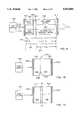
- FIG. 1is a schematic diagram of a dual frequency microlaser in accordance with the invention
- FIG. 2is an energy level diagram of neodymium orthovanadate (Nd:YVO 4 );
- FIG. 3is an embodiment of the dual wavelength microlaser of the invention in which the pump beam is lens coupled into the solid state gain medium;
- FIG. 4is an alternative embodiment of the dual wavelength microlaser of the invention in which the pump beam is butt-coupled into the solid-state gain medium;
- FIG. 5is another alternative embodiment of the dual wavelength microlaser in which an optical fiber is utilized to transmit the pump beam from the pump source into the solid-state gain medium;
- FIG. 6is a diagram illustrating absorption of a highly absorptive pump wavelength in gain material
- FIG. 7is a diagram illustrating a parallel polarization of dual wavelengths in the optical cavity of the invention.
- FIG. 8is a diagram of perpendicularly polarized dual wavelengths in the optical cavity of the invention.
- FIG. 9is a schematic diagram of an intracavity mixed microlaser in accordance with the invention.
- FIG. 10is a diagram of an alternative embodiment of an intracavity mixed microlaser of the invention in which the solid-state gain material is bonded to the nonlinear crystal and the crystal faces are coated directly on opposing surfaces of the gain material and nonlinear crystal;
- FIG. 11is a diagram of an alternative embodiment as in the FIG. 10 except that a dielectric spacer is positioned between the gain material and the non-linear crystal;
- FIG. 12is a diagram of an alternative embodiment of the invention in which the input face to the gain material is convex;
- FIG. 13is a diagram of a further alternative embodiment of the invention in which the output face of the non-linear crystal is convex.
- FIG. 14shows a linear array of composite cavity microlasers as an alternative embodiment of the invention.
- Laser radiation produced by a lasant material in an optical cavitycan be single longitudinal mode in character or it can have two or more longitudinal modes. Except where specific reference is made to the longitudinal mode structure, reference herein to laser radiation as having a specific frequency or specific wavelength will be understood to include one or more of the longitudinal modes of substantially the same frequency which are generated by the lasant material and are supported within the optical cavity. While this invention is susceptible of having many different forms, described herein are specific exemplary embodiments of the invention.
- the dual wavelength laser of the inventionincludes a solid-state gain (or "lasant") material 100 disposed within an optical cavity 110 defined by two dual wavelength reflectors 112 and 114.
- a pump beam 118is generated by a suitable pump source 120, and applied to end pump the solid state gain material 100 through the input reflector 112.
- a beam of laser radiation comprising two wavelengthsis generated in the optical cavity 110, and a dual wavelength output 130 is supplied through the output reflector 114.
- the solid-state gain material 100is selected to be a type that has at least two separate lasing transitions, and therefore, can lase at two separate, distinct wavelengths.
- the dual wavelength reflectors 112 and 114have reflectivities designed to reflect both of those wavelengths.
- a preferred solid-state gain materialincludes a rare-earth ion, such as trivalent neodymium (Nd 3+ ), doped into a suitable host material such as YVO 4 and yttrium lithium fluoride whose formula is YLiF 4 ("YLF").
- the Nd 3+ ionhas at least two possible lasing transitions: for example, in YVO 4 , neodymium has a first lasing transition at around 1064 nm (the 4 F 3/2 to 4 I 11/2 transition) and a second lasing transition at around 1342 nm (the 4 F 3/2 to 4 I 13/2 transition).
- suitable solid lasant materialsinclude substances wherein the active material is a stoichiometric component of the lasant material such as, neodymium pentaphosphate, and lithium neodymium tetraphosphate ("LNP").
- LNPlithium neodymium tetraphosphate
- the resonant optical cavity 110 of the laseris defined by the input reflector 112, closest to the pump beam, and by the output reflector 114, distal thereto, through which the dual wavelength output beam 130 is supplied.
- the input reflector 112has a high reflectivity at the two fundamental wavelengths produced by lasing the gain material (e.g., 1064 nm and 1342 nm where a gain material of Nd:YVO 4 is used) to support lasing action within the optical cavity 110.
- the input reflector 112has a high transmission at the pumping wavelength (e.g., 809 nm for a conventional laser diode used as a pumping source) to allow the pumping radiation 118 to reach the solid state lasant material 100.
- the output reflector 114is partially reflective at both fundamental wavelengths in order to provide high intensity intracavity radiation that supports lasing action, while allowing sufficient radiation to leak through to provide an output.
- the reflectivities of each respective wavelength at the output couplercan be varied.
- the output coupler's reflectivity at 1064can be made less than that at 1342 nm to introduce higher losses at 1064 to compensate for the stronger transition at 1064.
- the gain curves respectively corresponding to the first lasing transition and the second lasing transitionscan be approximately made equal. However, it is not necessary that the gain curves be exactly equal. The following discussion demonstrates how the reflectivities should be set to optimize dual-wavelength lasing operation.
- ⁇ and rbe, respectively, the stimulated emission cross-section and the mirror reflectivity, with the subscripts 1 and 2 used to denote these qualities at the two different laser frequencies of interest.
- ⁇is the loss coefficient of the gain medium at length L.
- ⁇ 2is the stronger emission cross-section.
- the essence of the above equationis that a functional relationship exists between the desired reflectivities. In practice one would maximize the reflectivity for the weaker line (r 1 ) and then design r 2 to satisfy the above relationship.
- the solid-state gain material 100defines a block having two opposing faces.
- the blockhas the form of a thin etalon.
- etalongenerally refers to a block with parallel faces and the term “thin” as used herein means an etalon preferably less than about 2.0 mm thick. Since it is not necessary that the crystal faces of the gain material be parallel in every embodiment, the term “block” will be used in some instances to refer to the element more broadly.
- the block of gain materialcomprises a rare-earth-doped crystal etalon with two opposite, flat, parallel, polished faces. Due to material limitations at the present time, the gain material would not be likely to function as desired if it were thinner than 0.1 millimeters.
- the input reflector 112is coupled closely to the solid state gain material 100 in order to "pin" (or locate) the gain as closely as possible to the input reflector, which defines one end of the optical cavity 110.
- pinning the gain close to the input reflector 112promotes single longitudinal mode operation of both the first and the second wavelengths.
- the input reflector 112is formed directly on a first face of the block of gain material.
- the output reflector 114is formed directly on the opposing face.
- one or both of the reflectorsmay comprise a separate substrate of, for example, a high quality optical glass, and a reflective surface formed thereon. Different reflector configurations are illustrated and discussed more fully with reference to the embodiments of FIGS. 3, 4, and 5.
- the pump source 120supplies the pump beam 118 to the solid-state gain material 100, thereby providing energy to raise the lasant mechanism (e.g., Nd 3+ ions within a crystal lattice) to a higher energy level.
- the pump beam 118is supplied longitudinally, i.e., substantially parallel with the optical cavity 110.
- the pumping radiation emitted by the optical pump sourceshould be matched with a suitable absorption band of the lasant material.
- any device producing optical pumping radiation having a wavelength effective to pump the lasant materialcan be used as the pump source in the practice of this invention.
- the pumping radiationis strongly absorbed by the lasant material and therefore the pumping radiation is absorbed quickly in a short depth. For example, in Nd:YVO 4 , a wavelength of 809 nm is strongly absorbed.
- Suitable optical pumping sourcesinclude laser diodes, laser diode arrays, and light-emitting diodes (LEDs), including super-luminescent diodes and super-luminescent diode arrays and laser diode arrays. LEDs and laser diodes are available which, as a function of composition, produce output radiation having a wavelength within a range from about 630 nm to about 1600 nm.
- a suitable pump sourceis a laser diode that emits a near-infrared wavelength.
- the wavelength of the output radiation from an aluminum gallium indium phosphide (AlGaInP) based devicecan be varied from about 630 nm to about 700 nm by variation of the device's composition.
- the wavelength of the output radiation from a gallium aluminum arsenide (GaAlAs) based devicecan be varied from about 750 nm to about 900 nm by variation of the device's composition.
- indium gallium arsenic phosphide (InGaAsP)-based devicescan be used to provide radiation in the wavelength range from about 1000 nm to about 1600 nm.
- a laser diodeis attached to a heat sink which cools the laser diode during operation.
- Such cooling devicesare commonly attached to a heat sink and packaged in a metal housing together with the laser diode.
- the heat sinkcan be passive in character, and in other embodiments the heat sink can comprise a thermoelectric cooler or other active temperature regulation system to help maintain the laser diode pumping source at a constant temperature and thereby ensure optimal operation of the laser diode at a constant wavelength.
- thermoelectric coolerany heat sink, thermoelectric cooler (TEC) or packaging that may be associated with a laser diode, a light-emitting diode, or an array of laser diodes or light-emitting diodes, is also included, all being conventional and readily understood by a person of ordinary skill in the art.
- FIG. 2is an energy level diagram of the solid state gain material Nd:YVO 4 .
- the energy level diagramshows that at least two substantial lasing transitions are possible: the 4 F 3/2 to 4 I 11/2 transition (1064 nm) shown at 200 and the 4 F 3/2 to 4 I 3/2 transition (1342 nm) shown at 210.
- the pump radiation at 809 nmraises the energy level of the lasant ions to a high level, and then by a process of phonon decay 222, their energy level drops to the 4 F 3/2 level.
- the lasant ioncan have at least two possible transitions: the first transition 200 at 1064 nm and the second transition 210 at 1342 nm.
- the first lasing transitionprovides the first wavelength and the second lasing transition provides the second wavelength.
- the first lasing transition at 1064is stronger than the 1342 nm transition.
- FIGS. 3, 4, and 5show several different configurations of gain material, reflectors, and couplers for coupling the optical pumping radiation from the semiconductor light source into the gain material. Each provides high intensity pumping radiation where it interacts with the gain material, thereby providing a high photon-to-photon conversion efficiency in the lasant material.
- FIG. 3illustrates a "lens-coupled” configuration for coupling the output of a pump source comprising a semiconductor laser diode 300 into the gain material 100.
- the semiconductor laser diode 300which has a narrow aperture, supplies a rapidly diverging beam 304 to a lens 306 that focuses the beam at a focal point 308 within the gain material 100.
- the term "lens” as used hereinis defined to comprise any conventional focusing device such as a gradient index (i.e., GRIN) lens, a ball lens, an aspheric lens, an optical fiber positioned cross-wise, or a combination of lenses.
- GRINgradient index
- the gain material 100is formed in a block 310 that includes a first face 312 and a second, opposing face 314.
- the input reflector 112is coated directly on the first face 312.
- the second face 314is anti-reflection coated for transmission at both fundamental wavelengths.
- the output reflector 114is formed on a suitable optical substrate 316, such as BK-7 glass.
- a suitable optical substrate 316such as BK-7 glass.
- an optical cavity 320is defined between the input reflector 112 and the output reflector 114.
- the laser diode 300, the lens 306, and the gain material 310are all positioned so that the focal point of the lens 306 is situated within the gain material 100 but still close to the face 312.
- the lens 306focuses the pump beam 304 through the input reflector 112 and into the block 310, where it pumps the lasant ions to a high energy level. Focusing the output radiation advantageously provides high pumping intensity within the gain material 100, which results in a very high photon-to-photon conversion efficiency. Furthermore, in some embodiments, the focal point is positioned to provide a very small cross-sectional area so that approximately only one single transverse mode of laser operation (i.e. TEM 00 mode) is supported. To most efficiently accomplish such single transverse mode operation, optical pumping radiation is delivered directly along a longitudinal optical path in the lasant material.
- TEM 00 modesingle transverse mode
- laser operationensues within the optical cavity 320, generating a single beam 330 of laser radiation having components that include both the first and the second wavelengths.
- FIG. 4illustrates a preferred embodiment in which the pump source includes a semiconductor light source 400, preferably a laser diode, that has an output facet 404 situated in a "butt-coupled" configuration with respect to the gain material 100, which obviates the need for a lens.
- the gain material 100is formed in a block 410 that includes a first face 412 and a second, opposing face 414.
- the input reflector 112is coated directly on the first face 412, and the output reflector 114 is coated directly on the second face 414, defining an optical cavity 420 between the input reflectors.
- the output facet of the laser diode 400is closely coupled to the input reflector 112 and the first face 412 of the block 410.
- the output facet 404is sufficiently close that the rapidly diverging beam of optical pumping radiation emanating therefrom optically end-pumps only a small transverse cross-sectional area within the block 410 of lasant material and supplies sufficient intensity within the gain material 100 to provide a high photon-to-photon conversion efficiency.
- the output facet 404is close enough to support essentially only one single transverse mode of laser operation (i.e., TEM 00 mode operation).
- the embodiment of FIG. 4provides a compact package that is efficient, cost-effective, and reliable in operation. Furthermore, because both reflectors 112 and 114 are bonded to the block 410 of gain material, and also because the laser diode 400 is coupled directly to the reflector 112 on the block 410, the laser is not subject to misalignment problems that can occur in other embodiments when one or both reflectors are separated from the gain material or when the pump source is not structurally coupled to the block.
- the pump sourceincludes a semiconductor light source 500, preferably a laser diode, that has an output facet 504 optically coupled to an optical fiber 506 that, on an output end 508, is coupled into the gain material 100.
- the gain material 100is formed in a block 510 that includes a first face 512 and a second, opposing face 514.
- the input reflector 112is coated directly on the first face 512
- the output reflector 114is coated directly on the second face 514, defining an optical cavity 520 between the reflectors.
- the output end of the fiber 506is closely coupled to the input reflector 112 and the first face 512 of the block 510 so that the diverging beam of optical pumping radiation emanating therefrom optically end-pumps only a small transverse cross-sectional area within the block 510 of lasant material and thereby provides a high photon-to-photon conversion efficiency.
- a fiber-coupled configurationcan provide a pumping spot small enough to efficiently accomplish single transverse mode laser operation (i.e., TEM 00 mode operation).
- the embodiment of FIG. 5provides a system that is efficient, cost-effective, and reliable in operation for some uses.
- the fiber optic linkallows the laser diode to be physically separated from the gain material block 510, which can be advantageous for some applications. Because both reflectors 112 and 114 are bonded to the block 510 of gain material, the laser is not subject to misalignment problems that can occur in other embodiments when one or both reflectors are separated from the gain material.
- FIG. 6shows the high absorption of the pump wavelength in the solid state-gain material.
- the gain material 100is optically pumped by the pumping source 120 at a wavelength ⁇ pump that matches a suitable absorption band of the gain material.
- the pumping radiationis strongly absorbed by the lasant material and as a result, its absorption depth is small.
- the wavelength separation of the two oscillating modes and their relationship to the absorption depth of the pump radiationfacilitates efficient dual wavelength operation.
- a spatially dependent distribution of the gainresults, in conformance with the standing wave pattern of the oscillating wavelength ⁇ 1 .
- This spatial distributionis further modified by the exponential absorption of the pump radiation so that only one longitudinal mode at ⁇ 1 oscillates (that at the longitudinal mode closest to the highest point under the gain curve of the material centered at ⁇ 1 ).
- ⁇ 1is the phase differential and is approximately equal to the distance which ⁇ 1 and ⁇ 2 are 180° out of phase
- n ⁇ 2is the index of refraction of the gain material
- ⁇is its absorption coefficient for the pump radiation.
- FIG. 7 and FIG. 8represent the different polarizations that can be obtained using gain crystals that have preferred lasing orientations.
- FIG. 7illustrates a dual output beam 130 emanating from the output coupler 114.
- the first wavelength ⁇ 1is illustrated as having a polarization illustrated by an arrow 700 that is parallel to the polarization illustrated by the arrow 710 for ⁇ 2 .
- the first wavelengthhas a polarization that is parallel to that of the second wavelength.
- the polarizationsmay not be exactly parallel.
- a gain material of Nd:YVO 4is oriented within the cavity so that the c-axis is perpendicular to the propagation axis of the beam within the laser cavity.
- the pump beamis applied to the gain material so that its polarization is parallel with the c-axis.
- the preferred polarization for both emissions(at 1064 nm and 1342 nm) is parallel to the c-axis, and therefore the output beam 130 has the parallel polarizations illustrated in FIG. 7.
- FIG. 8represents a configuration in which the first wavelength ⁇ 1 has a polarization illustrated by the arrow 800 while the second wavelength ⁇ 2 has a polarization 810 perpendicular to polarization 800.
- This polarizationis achieved by selecting a particular crystal orientation for the gain material within the optical cavity to provide the preferred polarizations. For example, in ND:YLF the strongest transition from the 4 F 3/2 to the 4 I 13/2 level at 1314 nm is found to be polarized perpendicular to the crystal c-axis, while the strongest transition from the 4 F 3/2 to the 4 I 11/2 level at 1047 nm is found to be parallel to the crystal c-axis. Thus, the two possible lasing wavelengths are perpendicular to one another.
- the intracavity-mixed laserincludes a solid-state gain material 900 and a nonlinear crystal 906 disposed within an optical cavity 910 defined by an input reflector 912 and an output reflector 914.
- the solid-state gain material 900is selected to be a type that has at least two lasing transitions and therefore, can lase at two separate, distinct wavelengths, denoted by ⁇ 1 and ⁇ 2 . Each wavelength has a preferred lasing orientation.
- the gain material 900is oriented with respect to the nonlinear crystal 906 so that the output propagation axis of the two wavelengths are collinear and phase-matched for optical frequency mixing.
- a pump beam 918is generated by a suitable pump source 920, and applied to end pump the solid state gain material 900 through the input reflector 912.
- a high intensity beam of dual wavelength laser radiation at ⁇ 1 and ⁇ 2is generated, and remains contained within the cavity 910 by the reflectors 912 and 914.
- This dual wavelength, high intensity intra-cavity beamis frequency mixed within the nonlinear crystal 906, and the resultant frequency-mixed output at ⁇ fm is supplied through the output reflector 914.
- the pumping diode energy at 809 nmenters at the input face, and as illustrated at 930 and 932, causes lasing at the first wavelength ⁇ 1 and the second wavelength ⁇ 2 respectively within the composite cavity 910.
- the round tripresults in a sum-frequency mixing to ⁇ sfm as illustrated at 940. Because of the output face's high transmissivity for light energy at that frequency (as low as 50% to as high as 99%), laser radiation at ⁇ sfm is transmitted from the composite cavity as useful visible laser energy.
- the two wavelengthsare combined in a suitable nonlinear crystal that forms part of the composite cavity to generate radiation at wavelength ⁇ sfm , via a phase-matched sum-frequency mixing process.
- the two wavelengthscan be combined via a phase-matched difference frequency mixing process to generate radiation at ⁇ dfm .
- the frequency mixing processsatisfies the following two relations: ##EQU3##
- the gain material 900is oriented with respect to the nonlinear crystal 906 so that the output propagation axis of the two wavelengths ⁇ 1 and ⁇ 2 are collinear and are phase-matched for optical frequency mixing.
- the nonlinear crystalmust be suitable for Type I phase matching.
- Type I phase matching crystalsinclude lithium borate (LBO) and lithium niobate (LiNBO). If the two oscillating wavelengths have polarizations which are perpendicular to one another as shown in FIG. 8, the nonlinear crystal must be suitable for Type II phase matching.
- An example of Type II phase matching crystalsincludes potassium titanyl phosphate KTP.
- the resonant optical cavity 910 of the intracavity-mixed laseris defined by the input reflector 912 and the output reflector 914.
- the input reflector 912is closest to the pump source 920.
- Both the input reflector 912 and the output reflector 914have a high reflectivity at the two fundamental wavelengths ( ⁇ 1 and ⁇ 2 ) produced by lasing the gain material (e.g., 1064 nm and 1342 nm where a gain material of Nd:YVO 4 is used) to support a high intensity beam within the optical cavity 910.
- the gain materiale.g., 1064 nm and 1342 nm where a gain material of Nd:YVO 4 is used
- the input reflector 912has a high transmissivity at the pumping wavelength (e.g., 809 nm for a conventional laser diode used as a pumping source) to allow the pumping radiation 918 to reach the solid state lasant material 900.
- the pumping wavelengthe.g. 809 nm for a conventional laser diode used as a pumping source
- the interior facesinclude a first interior face 950 formed on the gain material 900 and a second interior face 952 formed on the opposite face of the non-linear crystal 906. These interior faces are both coated for high transmissivity at the fundamental wavelength ⁇ 1 and ⁇ 2 . Either or both could be coated for high reflection at the frequency mixed wavelength ⁇ fm .
- the reflectivities of each of the crystal facesare designed to maximize the circulating flux within the resonator. These reflectivities range between 99.5% and >99.9% for the wavelengths ⁇ 1 and ⁇ 2 for the input and output reflectors 912 and 914, and between 0% and 0.25% for the interior faces 950 and 952.
- the reflectivities for ⁇ sfm (for sum-frequency mixing) and ⁇ dfm (for difference-frequency mixing)range between 80% and 100% on the input reflector 912 and between 0% and 10% on the output reflector 914, the first interior face 950, and the second interim face 952. This reflectivity arrangement enables low threshold pumping to achieve lasing at both wavelengths ⁇ 1 and ⁇ 2 .
- a preferred solid-state gain material 900includes a rare-earth ion, such as trivalent neodymium (Nd 3+ ), doped into a suitable host material such as YVO 4 , and YLF.
- the Nd 3+ ionhas at least two possible lasing transitions: a first lasing transition around 1064 nm (the 4 F 3/2 to 4 I 11/2 transition) and a second lasing transition (the 4 F 3/2 to 4 I 13/2 transition) around 1342 nm.
- a 594 nm outputresults from sum-frequency mixing the laser radiation generated from the 4 F 3/2 to 4 I 11/2 (1064 nm) and 4 F 3/2 to 4 I 13/2 (1342 ⁇ m) transitions.
- suitable solid lasant materialsinclude substances wherein the active material is a stoichiometric component of the lasant material (e.g., neodymium yttrium aluminum borate or NYAB). Such materials include, for example, neodymium pentaphosphate and lithium neodymium tetraphosphate ("LNP").
- LNPlithium neodymium tetraphosphate
- Detailed summaries of conventional solid lasant materialsare set forth in the Weber, Ed., CRC Handbook of Laser Science and Technology, Vol. I, CRC Press, Inc., Boca Raton, Fla., 1982 pp. 72-135 and by Kaminskii, Laser Crystals, Vol. 14 of the Springer Series in Optical Sciences, D. L. Mac-Adam, Ed., Springer-Verlag, New York, N.Y., 1981.
- the solid-state gain material 900defines a block having two opposing faces.
- the blockhas the form of a thin etalon.
- etalongenerally refers to a block with parallel faces and the term “thin” as used herein means an etalon preferably less than 2.0 mm thick.
- the gain materialwould not be likely to function as desired if it were thinner than 0.1 mm. Since it is not necessary that the faces of the block of gain material be parallel in every embodiment, the term “block” will be used in some instances to refer to the element more broadly.
- the input reflector 912is coupled closely to the solid state gain material 900 in order to "pin" the gain as closely as possible to the input reflector, which defines one end of the optical cavity 910.
- pinning the gain close to the input reflector 912promotes single longitudinal mode operation of both the first and the second wavelengths.
- the input reflector 912is formed directly on the input face of the block of solid state gain material 900 and the output reflector 914 is formed directly on the distal face of the nonlinear crystal 906.
- one or both of the reflectors 912 and/or 914may comprise a separate substrate of, for example, a high quality optical glass, and a reflective surface formed thereon.
- Nonlinear crystal 906Materials suitable for use as a nonlinear crystal 906 include those which have nonlinear optical properties.
- the most common nonlinear crystalscomprise inorganic compounds.
- non-linear optical propertiesare possessed by materials having the formula MTiO(XO 4 ) where "M” is at least one of the elements potassium (K) and rubidium (Rb), and "X” is at least one of the elements phosphorus (P) or arsenic (As).
- This generic formulaincludes potassium titanyl phosphate KTiOPO 4 (KTP), a particularly useful nonlinear material for second-harmonic generation.
- nonlinear optical materialsinclude, but are not limited to KH 2 PO 4 or KDP, LiNbO 3 , KNbO 3 , ⁇ -BaB 2 O 4 or BBO, Ba 2 NaNb 5 O 15 , LilO 3 , KB 5 O 8 .4H 2 O, potassium lithium niobate, urea and organic nonlinear materials.
- KH 2 PO 4 or KDPLiNbO 3 , KNbO 3 , ⁇ -BaB 2 O 4 or BBO
- Ba 2 NaNb 5 O 15LilO 3 , KB 5 O 8 .4H 2 O
- potassium lithium niobateurea and organic nonlinear materials.
- the nonlinear crystal 906may have the form of a cylinder with a diameter at least sufficient to contain the dual wavelength beam.
- this cylinderhas a length between 0.1 to 12.0 mm and is polished to etalon tolerances.
- the face of the nonlinear crystal closest to the gain materialis coated for high transmission (i.e., greater than 99.9%) at the fundamental wavelengths and at the output wavelength.
- the opposite faceis coated for high reflection at the fundamental wavelengths and for high transmission (typically greater than 90%) at the harmonic output wavelength.
- the gain material 900comprises neodymium yttrium orthovanadate (Nd:YVO 4 ) and the nonlinear crystal 906 comprises lithium borate (LBO), cut to provide phase matching for a sum frequency mixing process.
- a suitable pumping source 920includes at least one gallium aluminum arsenide (GaAlAs) diode laser emitting at a wavelength of 809 nm.
- the block 1010 of gain material 900comprises a rare earth doped crystal and has the form of an etalon with two opposite, flat, parallel polished faces.
- a nonlinear crystal block 1020which is bonded thereto as illustrated at 1024, has a cylindrical shape with two opposite flat, parallel polished faces. Bonding between the two blocks 1010 and 1020 can be accomplished by using an optical contact, diffusion bonding, optical cement, or an index matching fluid epoxy, among others.
- the nonlinear crystal block 1020would normally be about 0.1 to 12.0 mm long with the gain crystal block 1010 being 0.1 to 2 mm between flat faces.
- the nonlinear optical frequency mixing crystalis preferably less than approximately 10 mm long.
- the distance between the exterior faces of the cavityranges between about 0.2 and 14 mm.
- a 594 nm outputresults from sum-frequency mixing, the laser radiation generated from the 4 F 3/2 to 4 I 11/2 (1064 nm) and 4 F 3/2 to 4 I 13/2 (1342 nm) transitions.
- an outer (or pumping) face 1030 of the gain material block 1010is coated for high reflectivity at the two fundamental wavelengths ⁇ 1 and ⁇ 2 produced by lasing the gain material (e.g., 1064 nm and 1342 nm where a gain material of Nd:YVO 4 is used) and high transmission at the pump wavelength (e.g., 809 nm).
- the pumping face 1030may also be coated with a dielectric for high reflection (HR) at ⁇ sfm (for sum-frequency mixing) or ⁇ dfm (for difference-frequency mixing).
- the resonant optical cavityis defined by an input reflective surface 1030 coated directly on the gain material block 1010 and an output reflective surface coated directly on the nonlinear crystal block.
- An inner surface 1034 of the gain material, and the inner surface 1036 of the nonlinear crystalare antireflection-coated for both fundamental wavelengths.
- the two surfaces of the gain material and the two surfaces of the nonlinear crystalare polished flat and parallel to etalon tolerances (e.g., typical parallelism better than 2 arc-seconds).
- etalon tolerancese.g., typical parallelism better than 2 arc-seconds.
- FIG. 11discloses an embodiment similar to FIG. 10, except that it includes a dielectric spacer 1100 is inserted between the lasing material crystal block 1010 and the optical frequency mixing crystal block 1020.
- the spacer 1100is annular in shape and creates a small air gap 1110 between the crystals.
- the air gap 1110could be between 25 and 500 ⁇ m, and preferably is between 50 and 100 ⁇ m.
- the pumping source 920 and exterior end faces 1030 and 1032operate the same as described for the other embodiments.
- the interior faces 1034 and 1036are anti-reflection coated and their functions are substantially the same as the interior faces described above with reference to FIG. 10.
- the air gap 1100solves any difficulties in bonding the lasant material to the optical frequency mixing crystal that could otherwise compromise the integrity of the anti-reflection coatings for efficient operation of the laser.
- the spacer 1100provides a cost efficient coupling between the lasant material and the optical frequency mixing crystal, while maintaining the integrity of the anti-reflection coatings on either side of the air gap.
- both external end facesare flat and parallel, such a configuration is not necessary for functioning of the invention.
- one or both of the facescould be concave, or one face could be concave and the other convex.
- FIG. 12shows an embodiment similar to that of FIG. 11, except that a block 1200 of gain material 900 comprises a curved convex surface 1210 upon which the input reflector 912 may be formed.
- FIG. 13also shows an embodiment in which one of the faces of the cavity is convex.
- a block 1300 of the non-linear crystal 906comprises a convex surface 1310 upon which an output reflector may be formed. In either case the radius of curvature is greater than the distances between the faces of the etalon.
- FIG. 14illustrates a long block of solid state gain material 900 pumped by a linear array of pump spots 1400, such as could be generated by a stripe laser to create a linear array of sum or difference frequency microlasers.
- the array of pump spotscan be provided by any conventional pump source and/or optical technique such as an array of diode emitters, an array of fibers used to couple radiation from a pump source, or a diffractive beamsplitter.
- the pump spotsare provided through the input reflector 912 to a long block 1405 of solid-state gain material 900.
- a block 1410 of non-linear crystal material 906is bonded to the gain material as illustrated at 1024.
- the output reflector 914is formed on the opposite side of the non-linear block 906.
- the operation of the array configuration of FIG. 14advantageously provides a series of output beams 1420 at the frequency mixed wavelength ⁇ fm . It is advantageous that the laser of this invention employs separate crystals for lasing and for wavelength conversion, which permits use of readily available crystals that are more appropriate for their respective function. Particularly, using a separate gain material crystal allows selection of a gain material that is highly absorbing at the pump wavelength, which facilitates efficient operation of the laser at two distinct wavelengths.
Landscapes
- Physics & Mathematics (AREA)
- Electromagnetism (AREA)
- Nonlinear Science (AREA)
- Engineering & Computer Science (AREA)
- Plasma & Fusion (AREA)
- Optics & Photonics (AREA)
- Lasers (AREA)
Abstract
Description
TABLE I ______________________________________ REFLECTIVITIES Input Output Second Reflector Reflector First InteriorInterior Face Wavelength 912 914Face 950 952 ______________________________________ 809 nm (pump) <5% -- -- -- 1064 nm ≧99.9% ≧99.9% <0.25% <0.25% 1342 nm ≧99.9% ≧99.9% <0.25% <0.25% 594 nm (output) ≧90% ≦50% <1 <1% ______________________________________
Claims (50)
Priority Applications (1)
| Application Number | Priority Date | Filing Date | Title |
|---|---|---|---|
| US08/593,094US5802086A (en) | 1996-01-29 | 1996-01-29 | Single cavity solid state laser with intracavity optical frequency mixing |
Applications Claiming Priority (1)
| Application Number | Priority Date | Filing Date | Title |
|---|---|---|---|
| US08/593,094US5802086A (en) | 1996-01-29 | 1996-01-29 | Single cavity solid state laser with intracavity optical frequency mixing |
Publications (1)
| Publication Number | Publication Date |
|---|---|
| US5802086Atrue US5802086A (en) | 1998-09-01 |
Family
ID=24373356
Family Applications (1)
| Application Number | Title | Priority Date | Filing Date |
|---|---|---|---|
| US08/593,094Expired - LifetimeUS5802086A (en) | 1996-01-29 | 1996-01-29 | Single cavity solid state laser with intracavity optical frequency mixing |
Country Status (1)
| Country | Link |
|---|---|
| US (1) | US5802086A (en) |
Cited By (73)
| Publication number | Priority date | Publication date | Assignee | Title |
|---|---|---|---|---|
| US5963578A (en)* | 1996-07-26 | 1999-10-05 | Commissariat A L'energie Atomique | Microlaser cavity and microlaser with mode selection and manufacturing processes |
| US5966392A (en)* | 1997-02-25 | 1999-10-12 | National Science Council | Butt-coupling pumped single-mode solid-state laser with fiber-coupled diode |
| US6013912A (en)* | 1996-11-19 | 2000-01-11 | Commissariat A L'energie Atomique | Multispectral semiconductor resonant-cavity detector sensitive in at least two wavelength bands |
| US6018536A (en)* | 1998-11-20 | 2000-01-25 | Sarnoff Corporation | Multiple-wavelength mode-locked laser |
| US6026102A (en)* | 1997-04-21 | 2000-02-15 | Shimoji; Yukata | Multi element single mode microchip lasers |
| US6094445A (en)* | 1998-09-08 | 2000-07-25 | Simpatico Industries Co., Ltd. | High-efficiency cavity doubling laser |
| JP2000214506A (en)* | 1998-11-03 | 2000-08-04 | Toshiba Research Europe Ltd | Radiation light source and image pickup system |
| US6111900A (en)* | 1997-03-13 | 2000-08-29 | Ricoh Company, Ltd. | Solid-state laser apparatus and method with second harmonic wave features |
| GB2347756A (en)* | 1998-11-03 | 2000-09-13 | Toshiba Res Europ Ltd | A radiation source with frequency conversion member and imaging system |
| US6185236B1 (en) | 1999-02-02 | 2001-02-06 | University Of Central Florida | Self frequency double nd-doped: YCOB LASER |
| US6256328B1 (en)* | 1998-05-15 | 2001-07-03 | University Of Central Florida | Multiwavelength modelocked semiconductor diode laser |
| US6304237B1 (en)* | 1996-11-29 | 2001-10-16 | Corporation For Laser Optics Research | Monochromatic R,G,B laser light source display system and method |
| RU2177665C2 (en)* | 2000-03-28 | 2001-12-27 | Сычугов Владимир Александрович | Internally radiation-frequency doubling solid-state laser |
| US6404785B1 (en)* | 1998-02-11 | 2002-06-11 | The United States Of America As Represented By The Secretary Of The Navy | Solid state modulated ultraviolet laser |
| US6587496B1 (en)* | 2000-12-11 | 2003-07-01 | Lite Cycles, Inc. | Single-mode pump power source |
| US20030206565A1 (en)* | 2002-04-02 | 2003-11-06 | Ngk Insulators, Ltd. | Systems and a method for generating blue laser beam |
| US6647031B2 (en) | 1998-05-15 | 2003-11-11 | University Of Central Florida | Hybrid WDM-TDM optical communication and data link |
| US20030210558A1 (en)* | 2002-03-12 | 2003-11-13 | Fuji Photo Film Co., Ltd. | Light source device and light source device for image reading device |
| US6661816B2 (en) | 1998-06-11 | 2003-12-09 | University Of Central Florida | Multiwavelength modelocked lasers |
| US6671305B2 (en) | 1996-11-29 | 2003-12-30 | Corporation For Laser Optics Research | Solid state laser |
| US20040050280A1 (en)* | 2000-10-06 | 2004-03-18 | Alexey Rodin | Direct write holographic printer |
| US6711184B1 (en)* | 1999-09-21 | 2004-03-23 | Jenoptik Laser, Optik, Systeme Gmbh | Intracavity frequency-doubled diode-pumped laser |
| US20040076212A1 (en)* | 2002-10-18 | 2004-04-22 | Hiroshi Nunokawa | Solid state laser |
| US6801551B1 (en) | 1998-05-15 | 2004-10-05 | University Of Central Florida | Programmable multiwavelength modelocked laser |
| US20040218641A1 (en)* | 1999-05-26 | 2004-11-04 | Ii-Vi Incorporated | Optical contacting method and apparatus |
| US6836500B2 (en)* | 2000-08-31 | 2004-12-28 | Infineon Technologies Ag | Semiconductor laser chip and method for fabricating a semiconductor laser chip |
| US20050041717A1 (en)* | 2001-05-15 | 2005-02-24 | Fuji Photo Film Co., Ltd. | Laser-diode-excited laser apparatus, fiber laser apparatus, and fiber laser amplifier in which laser medium doped with one of Ho3+ , Sm3+, Eu3+, Dy3+, Er3+ and Tb3+ is excited with GaN-based compound laser diode |
| US20050052717A1 (en)* | 2001-10-16 | 2005-03-10 | David Brotherton-Ratcliffe | Holographic printer |
| US20050063441A1 (en)* | 2003-09-22 | 2005-03-24 | Brown David C. | High density methods for producing diode-pumped micro lasers |
| US20050094689A1 (en)* | 2002-04-27 | 2005-05-05 | Rofin-Sinar Laser Gmbh | Laser beam source with a laser element containing a thin crystal disk as a laser-active medium |
| US20050163176A1 (en)* | 2004-01-26 | 2005-07-28 | Li-Ning You | Green diode laser |
| US20050265411A1 (en)* | 2002-05-08 | 2005-12-01 | Takeuchi Eric B | Short wavelength diode-pumped solid-state laser |
| US20050276285A1 (en)* | 2004-06-15 | 2005-12-15 | National Tsing Hua University | Actively Q-switched laser system using quasi-phase-matched electro-optic Q-switch |
| US20060045161A1 (en)* | 2004-08-24 | 2006-03-02 | Minoru Kadoya | Intracavity sum-frequency mixing laser |
| US20060126682A1 (en)* | 2001-10-08 | 2006-06-15 | Geola Technologies Ltd. | Pulsed multiple colour laser system |
| FR2882860A1 (en)* | 2005-03-04 | 2006-09-08 | Oxxius Sa Sa | "TWO WAVELENGTH LASER DEVICE AND SYSTEM COMPRISING SUCH A DEVICE" |
| US20060209912A1 (en)* | 2005-03-18 | 2006-09-21 | Pavilion Integration Corporation | Monolithic microchip laser with intracavity beam combining and sum frequency or difference frequency mixing |
| US20060221434A1 (en)* | 2005-03-31 | 2006-10-05 | Kabushiki Kaisha Topcon | Laser oscillation device |
| US20060221439A1 (en)* | 2005-03-31 | 2006-10-05 | Michael Kuhnelt | Laser device |
| US20070002922A1 (en)* | 2005-06-30 | 2007-01-04 | Intel Corporation | Retro-reflecting lens for external cavity optics |
| WO2005117216A3 (en)* | 2004-05-25 | 2007-02-01 | Melles Griot Inc | Short wavelength diode-pumped solid-state laser |
| US20070121689A1 (en)* | 2003-09-22 | 2007-05-31 | Snake Creek Lasers Llc | Methods for Producing Diode-Pumped Micro Lasers |
| US20070166852A1 (en)* | 2003-09-22 | 2007-07-19 | Snake Creek Lasers Llc | Diode-pumped microlasers including resonator microchips and methods for producing the same |
| US20070217474A1 (en)* | 2005-12-20 | 2007-09-20 | Denso Corporation | Laser equipment |
| US20070297469A1 (en)* | 2004-09-28 | 2007-12-27 | Snake Creek Lasers, Llc | Cryogenically Cooled Solid State Lasers |
| US20080020083A1 (en)* | 2006-06-06 | 2008-01-24 | Kabushiki Kaisha Topcon | Method for joining optical members, structure for integrating optical members and laser oscillation device |
| US20080043788A1 (en)* | 2006-06-29 | 2008-02-21 | Tsuyoshi Suzudo | Laser-diode pumped solid-state laser apparatus, optical scanning apparatus, image forming apparatus and display apparatus |
| WO2007101029A3 (en)* | 2006-02-28 | 2008-04-10 | Quantronix Corp | Longitudinally pumped solid state laser and methods of making and using |
| US20080192790A1 (en)* | 2007-02-13 | 2008-08-14 | Aurotek Corporation | Laser diode |
| EP1810380A4 (en)* | 2004-09-23 | 2008-10-01 | Lighthouse Technologies Pty Lt | A selectable multiwavelength laser for outputting visible light |
| US20090034058A1 (en)* | 2006-01-04 | 2009-02-05 | Thierry Georges | Reduced threshold laser device |
| US7489437B1 (en) | 2007-12-05 | 2009-02-10 | Corning Incorporated | Fiber laser red-green-blue (RGB) light source |
| US20090279574A1 (en)* | 2008-05-12 | 2009-11-12 | Ipg Photonics Corporation | Frequency conversion laser head |
| US20100150186A1 (en)* | 2005-07-28 | 2010-06-17 | Matsushita Electric Industrial Co. Ltd | Laser light source and display device |
| WO2010017851A3 (en)* | 2008-03-03 | 2010-07-01 | Philipps-Universität Marburg | Laser-based terahertz and millimeter wave source |
| US20110069728A1 (en)* | 2009-09-22 | 2011-03-24 | Anthony Sebastian Bauco | Diode Pumped Ytterbium Doped Laser |
| US20110096802A1 (en)* | 2009-10-26 | 2011-04-28 | Dmitri Boutoussov | High power radiation source with active-media housing |
| WO2011053600A1 (en)* | 2009-10-26 | 2011-05-05 | Biolase Technology, Inc. | High power radiation source with active-media housing |
| WO2011140641A1 (en)* | 2010-05-11 | 2011-11-17 | Ye Hu | Packaging method of laser and nonlinear crystal and its application in diode pumped solid state lasers |
| US20120099184A1 (en)* | 2010-04-23 | 2012-04-26 | Horikawa Nobuyuki | Wavelength conversion laser light source and image display device |
| US20130272324A1 (en)* | 2012-04-11 | 2013-10-17 | Alfalight, Inc. | Monolithic Laser Cavity |
| US20130335813A1 (en)* | 2011-03-17 | 2013-12-19 | Hiroyuki Furuya | Wavelength conversion laser light source, and image display device |
| US20140011308A1 (en)* | 2012-07-05 | 2014-01-09 | Nanjing Cq Laser Technologies Co., Ltd. | Method for making laser module |
| CN103733112A (en)* | 2012-05-15 | 2014-04-16 | 京瓷晶体元件有限公司 | Etalon and manufacturing method of etalon |
| US20140366560A1 (en)* | 2003-11-15 | 2014-12-18 | Instrotek, Inc. | Device and Methods for Rapid Drying of Porous Materials |
| EP2924819A4 (en)* | 2012-11-26 | 2016-08-24 | Mitsubishi Electric Corp | LASER APPARATUS |
| US9553419B2 (en) | 2014-08-22 | 2017-01-24 | Bae Systems Information And Electronic Systems Integration Inc. | Shared multi-wavelength laser resonator with gain selected output coupling |
| US20170353000A1 (en)* | 2014-12-18 | 2017-12-07 | Ocuwave Ltd. | Laser system |
| WO2018215748A1 (en)* | 2017-05-23 | 2018-11-29 | M Squared Lasers Limited | Nonlinear crystal |
| US10148058B1 (en)* | 2016-02-23 | 2018-12-04 | Leidos, Inc. | Emission conversion amplifier for solid state lasers |
| US20240088622A1 (en)* | 2017-10-12 | 2024-03-14 | Osram Oled Gmbh | Semiconductor laser and method of production for optoelectronic semiconductor parts |
| JP7612115B1 (en)* | 2024-04-08 | 2025-01-10 | 三菱電機株式会社 | Laser Equipment |
| WO2025189202A1 (en)* | 2024-03-08 | 2025-09-12 | Pavilion Integration Corporation | Tunable uv laser |
Citations (13)
| Publication number | Priority date | Publication date | Assignee | Title |
|---|---|---|---|---|
| US4731787A (en)* | 1986-08-15 | 1988-03-15 | Board Of Trustees, Stanford University | Monolithic phasematched laser harmonic generator |
| US4739507A (en)* | 1984-11-26 | 1988-04-19 | Board Of Trustees, Stanford University | Diode end pumped laser and harmonic generator using same |
| US4847851A (en)* | 1988-05-19 | 1989-07-11 | University Of South Florida | Butt-coupled single transverse mode diode pumped laser |
| US4860304A (en)* | 1988-02-02 | 1989-08-22 | Massachusetts Institute Of Technology | Solid state microlaser |
| US4879723A (en)* | 1987-07-27 | 1989-11-07 | Amoco Corporation | Intracavity generation of coherent optical radiation of optical mixing |
| US4933947A (en)* | 1988-02-18 | 1990-06-12 | Amoco Corporation | Frequency conversion of optical radiation |
| US4942582A (en)* | 1989-04-24 | 1990-07-17 | Spectra-Physics | Single frequency solid state laser |
| US4956843A (en)* | 1989-10-10 | 1990-09-11 | Amoco Corporation | Simultaneous generation of laser radiation at two different frequencies |
| US5142542A (en)* | 1991-01-07 | 1992-08-25 | Amoco Corporation | Signal-resonant intracavity optical frequency mixing |
| US5249192A (en)* | 1991-06-27 | 1993-09-28 | Laserscope | Multiple frequency medical laser |
| JPH05341393A (en)* | 1992-06-08 | 1993-12-24 | Minolta Camera Co Ltd | Zoom lens driving device |
| US5333142A (en)* | 1992-10-26 | 1994-07-26 | The United States Of America As Represented By The Secretary Of The Navy | Technique for intracavity sum frequency generation |
| US5412674A (en)* | 1992-10-26 | 1995-05-02 | The United States Of America As Represented By The Secretary Of The Navy | Compact rapidly modulatable diode-pumped visible laser |
- 1996
- 1996-01-29USUS08/593,094patent/US5802086A/ennot_activeExpired - Lifetime
Patent Citations (13)
| Publication number | Priority date | Publication date | Assignee | Title |
|---|---|---|---|---|
| US4739507A (en)* | 1984-11-26 | 1988-04-19 | Board Of Trustees, Stanford University | Diode end pumped laser and harmonic generator using same |
| US4731787A (en)* | 1986-08-15 | 1988-03-15 | Board Of Trustees, Stanford University | Monolithic phasematched laser harmonic generator |
| US4879723A (en)* | 1987-07-27 | 1989-11-07 | Amoco Corporation | Intracavity generation of coherent optical radiation of optical mixing |
| US4860304A (en)* | 1988-02-02 | 1989-08-22 | Massachusetts Institute Of Technology | Solid state microlaser |
| US4933947A (en)* | 1988-02-18 | 1990-06-12 | Amoco Corporation | Frequency conversion of optical radiation |
| US4847851A (en)* | 1988-05-19 | 1989-07-11 | University Of South Florida | Butt-coupled single transverse mode diode pumped laser |
| US4942582A (en)* | 1989-04-24 | 1990-07-17 | Spectra-Physics | Single frequency solid state laser |
| US4956843A (en)* | 1989-10-10 | 1990-09-11 | Amoco Corporation | Simultaneous generation of laser radiation at two different frequencies |
| US5142542A (en)* | 1991-01-07 | 1992-08-25 | Amoco Corporation | Signal-resonant intracavity optical frequency mixing |
| US5249192A (en)* | 1991-06-27 | 1993-09-28 | Laserscope | Multiple frequency medical laser |
| JPH05341393A (en)* | 1992-06-08 | 1993-12-24 | Minolta Camera Co Ltd | Zoom lens driving device |
| US5333142A (en)* | 1992-10-26 | 1994-07-26 | The United States Of America As Represented By The Secretary Of The Navy | Technique for intracavity sum frequency generation |
| US5412674A (en)* | 1992-10-26 | 1995-05-02 | The United States Of America As Represented By The Secretary Of The Navy | Compact rapidly modulatable diode-pumped visible laser |
Non-Patent Citations (20)
| Title |
|---|
| de Barros et al., Two color Synchronously Mode locked Femtosecond Ti:Sapphire Laser, Optics Letters , vol. 18, No. 8 (1993), pp 631 633, No Month.* |
| de Barros et al., Two-color Synchronously Mode-locked Femtosecond Ti:Sapphire Laser, Optics Letters, vol. 18, No. 8 (1993), pp 631-633, No Month. |
| Dykaar et al., Sticky Pulses: Two color Cross mode locked Femtosecond Operation of a Single Ti:Sapphire Laser, Optics Letters , vol. 18, No. 8 (1993), pp. 634 636, No Month.* |
| Dykaar et al., Sticky Pulses: Two-color Cross-mode-locked Femtosecond Operation of a Single Ti:Sapphire Laser, Optics Letters, vol. 18, No. 8 (1993), pp. 634-636, No Month. |
| Evans et al., Dual wavelength Self mode locked Ti:Sapphire laser, Optics Letters , vol. 18, No. 13, (1993), pp. 1074 1076, No Month.* |
| Evans et al., Dual-wavelength Self-mode-locked Ti:Sapphire laser, Optics Letters, vol. 18, No. 13, (1993), pp. 1074-1076, No Month. |
| Henderson,A Computational Model of a Dual wavelength Solid state Laser, J. Appl. Phys ., vol. 68, No. 11 (1990), pp. 5451 5455, No Month.* |
| Henderson,A Computational Model of a Dual-wavelength Solid-state Laser, J. Appl. Phys., vol. 68, No. 11 (1990), pp. 5451-5455, No Month. |
| MacKinnon et al., A Laser Diode Array Pumped, Nd:YVO 4 /KTP, Composite Material Microchip Laser, Optics Communications 105 (1994), pp. 183 187, No Month.* |
| MacKinnon et al., A Laser Diode Array Pumped, Nd:YVO4 /KTP, Composite Material Microchip Laser, Optics Communications 105 (1994), pp. 183-187, No Month. |
| Shen et al., Comparison of Simultaneous Multiple Wavelength Lasing in Various Neodymium Host Crystals at Transitions from 4 F 3/2 4 I 11/2 and 4 F 3/2 4 I 13/2 , Appl. Phys. Lett ., vol. 56, No. 20 (1990), pp. 1937 1938, No Month.* |
| Shen et al., Comparison of Simultaneous Multiple Wavelength Lasing in Various Neodymium Host Crystals at Transitions from 4 F3/2 -4 I11/2 and 4 F3/2 -4 I13/2, Appl. Phys. Lett., vol. 56, No. 20 (1990), pp. 1937-1938, No Month. |
| Shen et al., Twice Sum frequency Mixing of a Dual Wavelength Nd:YALO 3 Laser to get 413.7 nm Violet Coherent Radiation in LilO 3 Crystal, J. Appl. Phys ., vol. 70, No. 3 (1991), pp. 1880 1881 , No Month.* |
| Shen et al., Twice Sum-frequency Mixing of a Dual-Wavelength Nd:YALO3 Laser to get 413.7-nm Violet Coherent Radiation in LilO3 Crystal, J. Appl. Phys., vol. 70, No. 3 (1991), pp. 1880-1881 , No Month. |
| Shen, Oscillation Condition of Simultaneous Multiple Wavelength Lasing, Chinese Phys. Lett . vol. 7, No. 4 (1990) pp. 174 176, No Month.* |
| Shen, Oscillation Condition of Simultaneous Multiple Wavelength Lasing, Chinese Phys. Lett. vol. 7, No. 4 (1990) pp. 174-176, No Month. |
| Tomaschke, Experimental and Theoretical Study of a Pulsed Dual Frquency Nd:YAG Laser with Intracavity Sum Frequency Mixing, CLEO 1990, pp. 252 253, No Month.* |
| Tomaschke, Experimental and Theoretical Study of a Pulsed Dual Frquency Nd:YAG Laser with Intracavity Sum Frequency Mixing, CLEO 1990, pp. 252-253, No Month. |
| Zayhowski, Microchip Lasers, The Lincoln Laboratory Journal , vol. 3, No. 3 (1990) pp. 427 445, No Month.* |
| Zayhowski, Microchip Lasers, The Lincoln Laboratory Journal, vol. 3, No. 3 (1990) pp. 427-445, No Month. |
Cited By (120)
| Publication number | Priority date | Publication date | Assignee | Title |
|---|---|---|---|---|
| US5963578A (en)* | 1996-07-26 | 1999-10-05 | Commissariat A L'energie Atomique | Microlaser cavity and microlaser with mode selection and manufacturing processes |
| US6013912A (en)* | 1996-11-19 | 2000-01-11 | Commissariat A L'energie Atomique | Multispectral semiconductor resonant-cavity detector sensitive in at least two wavelength bands |
| US6671305B2 (en) | 1996-11-29 | 2003-12-30 | Corporation For Laser Optics Research | Solid state laser |
| US6304237B1 (en)* | 1996-11-29 | 2001-10-16 | Corporation For Laser Optics Research | Monochromatic R,G,B laser light source display system and method |
| US6774881B2 (en) | 1996-11-29 | 2004-08-10 | Corporation For Laser Optics Research | Monochromatic R,G,B laser display system and method |
| US5966392A (en)* | 1997-02-25 | 1999-10-12 | National Science Council | Butt-coupling pumped single-mode solid-state laser with fiber-coupled diode |
| US6111900A (en)* | 1997-03-13 | 2000-08-29 | Ricoh Company, Ltd. | Solid-state laser apparatus and method with second harmonic wave features |
| US6026102A (en)* | 1997-04-21 | 2000-02-15 | Shimoji; Yukata | Multi element single mode microchip lasers |
| US6404785B1 (en)* | 1998-02-11 | 2002-06-11 | The United States Of America As Represented By The Secretary Of The Navy | Solid state modulated ultraviolet laser |
| US6801551B1 (en) | 1998-05-15 | 2004-10-05 | University Of Central Florida | Programmable multiwavelength modelocked laser |
| US6256328B1 (en)* | 1998-05-15 | 2001-07-03 | University Of Central Florida | Multiwavelength modelocked semiconductor diode laser |
| US6647031B2 (en) | 1998-05-15 | 2003-11-11 | University Of Central Florida | Hybrid WDM-TDM optical communication and data link |
| US6661816B2 (en) | 1998-06-11 | 2003-12-09 | University Of Central Florida | Multiwavelength modelocked lasers |
| US6094445A (en)* | 1998-09-08 | 2000-07-25 | Simpatico Industries Co., Ltd. | High-efficiency cavity doubling laser |
| GB2347756A (en)* | 1998-11-03 | 2000-09-13 | Toshiba Res Europ Ltd | A radiation source with frequency conversion member and imaging system |
| GB2347756B (en)* | 1998-11-03 | 2001-08-01 | Toshiba Res Europ Ltd | A radiation source and imaging system |
| JP2000214506A (en)* | 1998-11-03 | 2000-08-04 | Toshiba Research Europe Ltd | Radiation light source and image pickup system |
| US6388799B1 (en) | 1998-11-03 | 2002-05-14 | Toshiba Research Europe Limited | Optical device and imaging system |
| US6018536A (en)* | 1998-11-20 | 2000-01-25 | Sarnoff Corporation | Multiple-wavelength mode-locked laser |
| US6301275B2 (en) | 1999-02-02 | 2001-10-09 | University Of Central Florida | Self-frequency doubled Nd-doped YCOB laser |
| US6185236B1 (en) | 1999-02-02 | 2001-02-06 | University Of Central Florida | Self frequency double nd-doped: YCOB LASER |
| US20040218641A1 (en)* | 1999-05-26 | 2004-11-04 | Ii-Vi Incorporated | Optical contacting method and apparatus |
| US7072368B2 (en)* | 1999-05-26 | 2006-07-04 | Ii-Vi Incorporated | Optical contacting method and apparatus |
| US6711184B1 (en)* | 1999-09-21 | 2004-03-23 | Jenoptik Laser, Optik, Systeme Gmbh | Intracavity frequency-doubled diode-pumped laser |
| RU2177665C2 (en)* | 2000-03-28 | 2001-12-27 | Сычугов Владимир Александрович | Internally radiation-frequency doubling solid-state laser |
| US6836500B2 (en)* | 2000-08-31 | 2004-12-28 | Infineon Technologies Ag | Semiconductor laser chip and method for fabricating a semiconductor laser chip |
| US20040050280A1 (en)* | 2000-10-06 | 2004-03-18 | Alexey Rodin | Direct write holographic printer |
| US7199814B2 (en)* | 2000-10-06 | 2007-04-03 | Xyz Imaging, Inc. | Direct write holographic printer |
| US6587496B1 (en)* | 2000-12-11 | 2003-07-01 | Lite Cycles, Inc. | Single-mode pump power source |
| US7418023B2 (en)* | 2001-05-15 | 2008-08-26 | Fujifilm Corporation | Laser-diode-excited laser apparatus, fiber laser apparatus, and fiber laser amplifier in which laser medium doped with one of Ho3+, SM3+, EU3+, DY3+, ER3+ and TB3+ is excited with GaN-based compound laser diode |
| US20050041717A1 (en)* | 2001-05-15 | 2005-02-24 | Fuji Photo Film Co., Ltd. | Laser-diode-excited laser apparatus, fiber laser apparatus, and fiber laser amplifier in which laser medium doped with one of Ho3+ , Sm3+, Eu3+, Dy3+, Er3+ and Tb3+ is excited with GaN-based compound laser diode |
| US20060126682A1 (en)* | 2001-10-08 | 2006-06-15 | Geola Technologies Ltd. | Pulsed multiple colour laser system |
| US20100149499A1 (en)* | 2001-10-08 | 2010-06-17 | View Holographics Ltd. | Pulsed Multiple Colour Laser System |
| US7983316B2 (en) | 2001-10-08 | 2011-07-19 | Geola Technologies Ltd. | Pulsed multiple colour laser system |
| US7161722B2 (en) | 2001-10-16 | 2007-01-09 | Geola Technologies Ltd. | Holographic printer |
| US20050052717A1 (en)* | 2001-10-16 | 2005-03-10 | David Brotherton-Ratcliffe | Holographic printer |
| US20030210558A1 (en)* | 2002-03-12 | 2003-11-13 | Fuji Photo Film Co., Ltd. | Light source device and light source device for image reading device |
| US7034450B2 (en)* | 2002-03-12 | 2006-04-25 | Fuji Photo Film Co., Ltd. | Light source device and light source device for image reading device |
| US6807210B2 (en)* | 2002-04-02 | 2004-10-19 | Ngk Insulators, Ltd. | Systems and a method for generating blue laser beam |
| US20030206565A1 (en)* | 2002-04-02 | 2003-11-06 | Ngk Insulators, Ltd. | Systems and a method for generating blue laser beam |
| US20050094689A1 (en)* | 2002-04-27 | 2005-05-05 | Rofin-Sinar Laser Gmbh | Laser beam source with a laser element containing a thin crystal disk as a laser-active medium |
| US7200160B2 (en)* | 2002-04-27 | 2007-04-03 | Rofin-Sinar Laser Gmbh | Laser beam source with a laser element containing a thin crystal disk as a laser-active medium |
| US7197059B2 (en)* | 2002-05-08 | 2007-03-27 | Melles Griot, Inc. | Short wavelength diode-pumped solid-state laser |
| US20050265411A1 (en)* | 2002-05-08 | 2005-12-01 | Takeuchi Eric B | Short wavelength diode-pumped solid-state laser |
| US20040076212A1 (en)* | 2002-10-18 | 2004-04-22 | Hiroshi Nunokawa | Solid state laser |
| US6947465B2 (en)* | 2002-10-18 | 2005-09-20 | Orc Manufacturing Co., Ltd. | Solid state laser |
| US20050063441A1 (en)* | 2003-09-22 | 2005-03-24 | Brown David C. | High density methods for producing diode-pumped micro lasers |
| US20070121689A1 (en)* | 2003-09-22 | 2007-05-31 | Snake Creek Lasers Llc | Methods for Producing Diode-Pumped Micro Lasers |
| EP1670933A4 (en)* | 2003-09-22 | 2008-01-23 | Snake Creek Lasers Llc | High densiity methods for producing diode-pumped micro lasers |
| US20070166852A1 (en)* | 2003-09-22 | 2007-07-19 | Snake Creek Lasers Llc | Diode-pumped microlasers including resonator microchips and methods for producing the same |
| US20140366560A1 (en)* | 2003-11-15 | 2014-12-18 | Instrotek, Inc. | Device and Methods for Rapid Drying of Porous Materials |
| US9702626B2 (en)* | 2003-11-15 | 2017-07-11 | Instrotek, Inc. | Device and methods for rapid drying of porous materials |
| US20170284739A1 (en)* | 2003-11-15 | 2017-10-05 | Instrotek, Inc. | Device and Methods for Rapid Drying of Porous Materials |
| US20050163176A1 (en)* | 2004-01-26 | 2005-07-28 | Li-Ning You | Green diode laser |
| US7003006B2 (en)* | 2004-01-26 | 2006-02-21 | Li-Ning You | Green diode laser |
| WO2005117216A3 (en)* | 2004-05-25 | 2007-02-01 | Melles Griot Inc | Short wavelength diode-pumped solid-state laser |
| US20050276285A1 (en)* | 2004-06-15 | 2005-12-15 | National Tsing Hua University | Actively Q-switched laser system using quasi-phase-matched electro-optic Q-switch |
| US7433373B2 (en)* | 2004-06-15 | 2008-10-07 | National Tsing Hua University | Actively Q-switched laser system using quasi-phase-matched electro-optic Q-switch |
| US7187703B2 (en) | 2004-08-24 | 2007-03-06 | Showa Optronics Co., Ltd. | Intracavity sum-frequency mixing laser |
| US20060045161A1 (en)* | 2004-08-24 | 2006-03-02 | Minoru Kadoya | Intracavity sum-frequency mixing laser |
| EP1810380A4 (en)* | 2004-09-23 | 2008-10-01 | Lighthouse Technologies Pty Lt | A selectable multiwavelength laser for outputting visible light |
| US20070297469A1 (en)* | 2004-09-28 | 2007-12-27 | Snake Creek Lasers, Llc | Cryogenically Cooled Solid State Lasers |
| CN101138137B (en)* | 2005-03-04 | 2010-09-29 | 奥克休斯股份有限公司 | Dual wavelength laser device and system including the same |
| US20080192782A1 (en)* | 2005-03-04 | 2008-08-14 | Oxxius | Dual Wavelength Laser Device, and System Comprising Same |
| WO2006092509A1 (en)* | 2005-03-04 | 2006-09-08 | Oxxius | Dual wavelength laser device, and system comprising same |
| FR2882860A1 (en)* | 2005-03-04 | 2006-09-08 | Oxxius Sa Sa | "TWO WAVELENGTH LASER DEVICE AND SYSTEM COMPRISING SUCH A DEVICE" |
| US20060209912A1 (en)* | 2005-03-18 | 2006-09-21 | Pavilion Integration Corporation | Monolithic microchip laser with intracavity beam combining and sum frequency or difference frequency mixing |
| US7535937B2 (en) | 2005-03-18 | 2009-05-19 | Pavilion Integration Corporation | Monolithic microchip laser with intracavity beam combining and sum frequency or difference frequency mixing |
| US20060221434A1 (en)* | 2005-03-31 | 2006-10-05 | Kabushiki Kaisha Topcon | Laser oscillation device |
| US20090003393A1 (en)* | 2005-03-31 | 2009-01-01 | Osram Opto Semiconductors Gmbh | Solid-state laser device with a crystal array |
| US7729046B2 (en) | 2005-03-31 | 2010-06-01 | Osram Opto Semiconductors Gmbh | Solid-state laser device with a crystal array |
| US20060221439A1 (en)* | 2005-03-31 | 2006-10-05 | Michael Kuhnelt | Laser device |
| US20070002922A1 (en)* | 2005-06-30 | 2007-01-04 | Intel Corporation | Retro-reflecting lens for external cavity optics |
| US7907646B2 (en)* | 2005-07-28 | 2011-03-15 | Panasonic Corporation | Laser light source and display device |
| US20100150186A1 (en)* | 2005-07-28 | 2010-06-17 | Matsushita Electric Industrial Co. Ltd | Laser light source and display device |
| US7843987B2 (en) | 2005-12-20 | 2010-11-30 | Denso Corporation | Laser equipment |
| US20090238221A1 (en)* | 2005-12-20 | 2009-09-24 | Denso Corporation | Laser equipment |
| US7564890B2 (en)* | 2005-12-20 | 2009-07-21 | Denso Corporation | Laser equipment |
| US20070217474A1 (en)* | 2005-12-20 | 2007-09-20 | Denso Corporation | Laser equipment |
| US20090034058A1 (en)* | 2006-01-04 | 2009-02-05 | Thierry Georges | Reduced threshold laser device |
| WO2007101029A3 (en)* | 2006-02-28 | 2008-04-10 | Quantronix Corp | Longitudinally pumped solid state laser and methods of making and using |
| US20080020083A1 (en)* | 2006-06-06 | 2008-01-24 | Kabushiki Kaisha Topcon | Method for joining optical members, structure for integrating optical members and laser oscillation device |
| US7751457B2 (en)* | 2006-06-29 | 2010-07-06 | Ricoh Company, Ltd. | Laser-diode pumped solid-state laser apparatus, optical scanning apparatus, image forming apparatus and display apparatus |
| US20080043788A1 (en)* | 2006-06-29 | 2008-02-21 | Tsuyoshi Suzudo | Laser-diode pumped solid-state laser apparatus, optical scanning apparatus, image forming apparatus and display apparatus |
| EP1873875A3 (en)* | 2006-06-29 | 2008-08-20 | Ricoh Company, Ltd. | Laser-diode pumped solid state laser apparatus, optical scanning apparatus, image forming apparatus and display apparatus |
| US20080192790A1 (en)* | 2007-02-13 | 2008-08-14 | Aurotek Corporation | Laser diode |
| US7489437B1 (en) | 2007-12-05 | 2009-02-10 | Corning Incorporated | Fiber laser red-green-blue (RGB) light source |
| WO2010017851A3 (en)* | 2008-03-03 | 2010-07-01 | Philipps-Universität Marburg | Laser-based terahertz and millimeter wave source |
| US20090279574A1 (en)* | 2008-05-12 | 2009-11-12 | Ipg Photonics Corporation | Frequency conversion laser head |
| US8179934B2 (en)* | 2008-05-12 | 2012-05-15 | Ipg Photonics Corporation | Frequency conversion laser head |
| WO2011037848A3 (en)* | 2009-09-22 | 2012-01-12 | Corning Incorporated | Diode pumped ytterbium doped laser |
| US20110069728A1 (en)* | 2009-09-22 | 2011-03-24 | Anthony Sebastian Bauco | Diode Pumped Ytterbium Doped Laser |
| WO2011053604A1 (en)* | 2009-10-26 | 2011-05-05 | Biolase Technology, Inc. | High power radiation source with active-media housing |
| WO2011053600A1 (en)* | 2009-10-26 | 2011-05-05 | Biolase Technology, Inc. | High power radiation source with active-media housing |
| US20110096802A1 (en)* | 2009-10-26 | 2011-04-28 | Dmitri Boutoussov | High power radiation source with active-media housing |
| US8588268B2 (en) | 2009-10-26 | 2013-11-19 | Biolase, Inc. | High power radiation source with active-media housing |
| US20120099184A1 (en)* | 2010-04-23 | 2012-04-26 | Horikawa Nobuyuki | Wavelength conversion laser light source and image display device |
| US8456734B2 (en)* | 2010-04-23 | 2013-06-04 | Panasonic Corporation | Wavelength conversion laser light source and image display device |
| CN102893465B (en)* | 2010-05-11 | 2015-10-21 | 胡烨 | The method for packing of laser crystal and nonlinear crystal and the application in diode pumped solid state thereof |
| WO2011140641A1 (en)* | 2010-05-11 | 2011-11-17 | Ye Hu | Packaging method of laser and nonlinear crystal and its application in diode pumped solid state lasers |
| CN102893465A (en)* | 2010-05-11 | 2013-01-23 | 胡烨 | Packaging method of laser and nonlinear crystal and its application in diode pumped solid state lasers |
| US20130335813A1 (en)* | 2011-03-17 | 2013-12-19 | Hiroyuki Furuya | Wavelength conversion laser light source, and image display device |
| US9172201B2 (en)* | 2011-03-17 | 2015-10-27 | Panasonic Intellectual Property Management Co., Ltd. | Wavelength conversion laser light source, and image display device |
| US20130272324A1 (en)* | 2012-04-11 | 2013-10-17 | Alfalight, Inc. | Monolithic Laser Cavity |
| CN103733112B (en)* | 2012-05-15 | 2018-02-13 | 京瓷株式会社 | Etalon and manufacturing method of etalon |
| CN103733112A (en)* | 2012-05-15 | 2014-04-16 | 京瓷晶体元件有限公司 | Etalon and manufacturing method of etalon |
| US20140347735A1 (en)* | 2012-05-15 | 2014-11-27 | Kyocera Crystal Device Corporation | Etalon and method for producing etalon |
| US9197027B2 (en)* | 2012-07-05 | 2015-11-24 | C2C Link Corporation | Method for making laser module |
| US20140011308A1 (en)* | 2012-07-05 | 2014-01-09 | Nanjing Cq Laser Technologies Co., Ltd. | Method for making laser module |
| EP2924819A4 (en)* | 2012-11-26 | 2016-08-24 | Mitsubishi Electric Corp | LASER APPARATUS |
| US9553419B2 (en) | 2014-08-22 | 2017-01-24 | Bae Systems Information And Electronic Systems Integration Inc. | Shared multi-wavelength laser resonator with gain selected output coupling |
| US20170353000A1 (en)* | 2014-12-18 | 2017-12-07 | Ocuwave Ltd. | Laser system |
| US10036934B2 (en)* | 2014-12-18 | 2018-07-31 | Ocuwave Ltd. | Laser system |
| US10148058B1 (en)* | 2016-02-23 | 2018-12-04 | Leidos, Inc. | Emission conversion amplifier for solid state lasers |
| WO2018215748A1 (en)* | 2017-05-23 | 2018-11-29 | M Squared Lasers Limited | Nonlinear crystal |
| US11347130B2 (en) | 2017-05-23 | 2022-05-31 | M Squared Lasers Limited | Nonlinear crystal |
| EP3631577B1 (en)* | 2017-05-23 | 2024-06-26 | M Squared Lasers Limited | Nonlinear crystal |
| US20240088622A1 (en)* | 2017-10-12 | 2024-03-14 | Osram Oled Gmbh | Semiconductor laser and method of production for optoelectronic semiconductor parts |
| WO2025189202A1 (en)* | 2024-03-08 | 2025-09-12 | Pavilion Integration Corporation | Tunable uv laser |
| JP7612115B1 (en)* | 2024-04-08 | 2025-01-10 | 三菱電機株式会社 | Laser Equipment |
Similar Documents
| Publication | Publication Date | Title |
|---|---|---|
| US5802086A (en) | Single cavity solid state laser with intracavity optical frequency mixing | |
| EP0715774B1 (en) | Deep blue microlaser | |
| EP0943167B1 (en) | Frequency conversion laser | |
| US5070505A (en) | Self-doubling micro-laser | |
| US5708672A (en) | Dual wavelength solid state laser | |
| US5854802A (en) | Single longitudinal mode frequency converted laser | |
| US5063566A (en) | Internally-doubled, composite-cavity microlaser | |
| US5164947A (en) | Single-frequency, frequency doubled laser | |
| US4739507A (en) | Diode end pumped laser and harmonic generator using same | |
| US5182759A (en) | Apparatus and method for pumping of a weakly absorbing lasant material | |
| US4879722A (en) | Generation of coherent optical radiation by optical mixing | |
| US5317447A (en) | High-power, compact, diode-pumped, tunable laser | |
| US5142542A (en) | Signal-resonant intracavity optical frequency mixing | |
| US4879723A (en) | Intracavity generation of coherent optical radiation of optical mixing | |
| US6301275B2 (en) | Self-frequency doubled Nd-doped YCOB laser | |
| Inoue et al. | Diode-pumped Nd: YAG laser producing 122-W CW power at 1.319/spl mu/m | |
| US20050063441A1 (en) | High density methods for producing diode-pumped micro lasers | |
| WO1998025327A9 (en) | Frequency conversion laser | |
| US5856996A (en) | Compact efficient solid state laser | |
| US5341393A (en) | Laser-diode-pumped solid-state laser | |
| US6512630B1 (en) | Miniature laser/amplifier system | |
| Huber et al. | Compact diode pumped cw solid-state lasers in the visible spectral region | |
| US6389043B1 (en) | Efficient frequency-converted laser with single beam output | |
| US7593439B2 (en) | Laser diode-pumped monolithic solid state laser device and method for application of said device | |
| EP0457523A2 (en) | Apparatus and method for pumping of a weakly absorbing lasant material |
Legal Events
| Date | Code | Title | Description |
|---|---|---|---|
| AS | Assignment | Owner name:LASER POWER CORP., CALIFORNIA Free format text:ASSIGNMENT OF ASSIGNORS INTEREST;ASSIGNORS:HARGIS, DAVID E.;PESSOT, MAURICE A.;REEL/FRAME:007831/0045 Effective date:19960125 | |
| STCF | Information on status: patent grant | Free format text:PATENTED CASE | |
| AS | Assignment | Owner name:MELLES GRIOT, INC., CALIFORNIA Free format text:ASSIGNMENT OF ASSIGNORS INTEREST;ASSIGNOR:LASER POWER CORPORATION;REEL/FRAME:010892/0069 Effective date:20000606 | |
| FEPP | Fee payment procedure | Free format text:PAT HOLDER NO LONGER CLAIMS SMALL ENTITY STATUS, ENTITY STATUS SET TO UNDISCOUNTED (ORIGINAL EVENT CODE: STOL); ENTITY STATUS OF PATENT OWNER: LARGE ENTITY | |
| FPAY | Fee payment | Year of fee payment:4 | |
| FEPP | Fee payment procedure | Free format text:PAYOR NUMBER ASSIGNED (ORIGINAL EVENT CODE: ASPN); ENTITY STATUS OF PATENT OWNER: LARGE ENTITY | |
| FPAY | Fee payment | Year of fee payment:8 | |
| AS | Assignment | Owner name:CVI LASER, LLC, NEW MEXICO Free format text:ASSIGNMENT OF ASSIGNORS INTEREST;ASSIGNOR:MELLES GRIOT, INC.;REEL/FRAME:019605/0244 Effective date:20070716 | |
| AS | Assignment | Owner name:BANK OF AMERICA, N.A., AS ADMINISTRATIVE AGENT, WA Free format text:NOTICE OF GRANT OF SECURITY INTEREST;ASSIGNOR:CVI LASER, LLC;REEL/FRAME:019690/0167 Effective date:20070726 | |
| FPAY | Fee payment | Year of fee payment:12 |