US5801531A - Apparatus and method for testing magnetic heads using translational slides and a rotatable arm - Google Patents
Apparatus and method for testing magnetic heads using translational slides and a rotatable armDownload PDFInfo
- Publication number
- US5801531A US5801531AUS08/544,090US54409096AUS5801531AUS 5801531 AUS5801531 AUS 5801531AUS 54409096 AUS54409096 AUS 54409096AUS 5801531 AUS5801531 AUS 5801531A
- Authority
- US
- United States
- Prior art keywords
- translational
- magnetic head
- slide
- testing apparatus
- set forth
- Prior art date
- Legal status (The legal status is an assumption and is not a legal conclusion. Google has not performed a legal analysis and makes no representation as to the accuracy of the status listed.)
- Expired - Lifetime
Links
Images


Classifications
- G—PHYSICS
- G11—INFORMATION STORAGE
- G11B—INFORMATION STORAGE BASED ON RELATIVE MOVEMENT BETWEEN RECORD CARRIER AND TRANSDUCER
- G11B5/00—Recording by magnetisation or demagnetisation of a record carrier; Reproducing by magnetic means; Record carriers therefor
- G11B5/012—Recording on, or reproducing or erasing from, magnetic disks
- G—PHYSICS
- G11—INFORMATION STORAGE
- G11B—INFORMATION STORAGE BASED ON RELATIVE MOVEMENT BETWEEN RECORD CARRIER AND TRANSDUCER
- G11B33/00—Constructional parts, details or accessories not provided for in the other groups of this subclass
- G11B33/10—Indicating arrangements; Warning arrangements
- G—PHYSICS
- G11—INFORMATION STORAGE
- G11B—INFORMATION STORAGE BASED ON RELATIVE MOVEMENT BETWEEN RECORD CARRIER AND TRANSDUCER
- G11B5/00—Recording by magnetisation or demagnetisation of a record carrier; Reproducing by magnetic means; Record carriers therefor
- G11B5/455—Arrangements for functional testing of heads; Measuring arrangements for heads
- G—PHYSICS
- G11—INFORMATION STORAGE
- G11B—INFORMATION STORAGE BASED ON RELATIVE MOVEMENT BETWEEN RECORD CARRIER AND TRANSDUCER
- G11B5/00—Recording by magnetisation or demagnetisation of a record carrier; Reproducing by magnetic means; Record carriers therefor
- G11B5/48—Disposition or mounting of heads or head supports relative to record carriers ; arrangements of heads, e.g. for scanning the record carrier to increase the relative speed
- G11B5/4806—Disposition or mounting of heads or head supports relative to record carriers ; arrangements of heads, e.g. for scanning the record carrier to increase the relative speed specially adapted for disk drive assemblies, e.g. assembly prior to operation, hard or flexible disk drives
Definitions
- This inventionrelates to testing of magnetic disk drives and in particular to testing of components related to magnetic disk drives, such as magnetic disks, magnetic heads and the like.
- a magnetic disk drivetypically includes a stack of spaced apart, concentric magnetic disks mounted on a common spindle. Disposed adjacent to the stack of disks is an actuator arm assembly which comprises a plurality of arms extending into the spacings between the disks. Mounted on the distal end of each arm is a resilient load beam which in turn carries a magnetic head interacting with an associated magnetic disk.
- FIG. 1shows schematically a top plan view of a typical prior art magnetic disk drive signified by reference numeral 2.
- the disk drive 2includes an arm 4 revolvable about an arm axis 6, and a magnetic disk 8 rotatable about a spindle 10.
- Attached to *he distal end of the arm 4is an air bearing slider 13 carrying a magnetic head 14 which interacts with the magnetic disk 8.
- the disk 8spins at high speed in a rotational direction 15.
- the aerodynamics of the moving air between the slider 13 and the surface of the disk 8provides sufficient buoyancy to suspend the slider 13 above the disk surface.
- the height of the slider 13 above the disk surfaceis called the flying height of the magnetic head 14.
- the arm 4sweeps the head 14 in an arcuate locus 16 traversing the disk surface.
- the tangent line to the outermost track ODis labeled T OD
- the center line passing through the slider 13is signified by reference numeral 18.
- the angle between the center line 18 and the tangent line T OD of the outermost track ODis defined as the skew angle ⁇ OD .
- the angle between the center line 18 and the tangent line T ID of the innermost track IDis defined as the skew angle ⁇ OD .
- the skew angles ⁇ OD and ⁇ IDmay be different in magnitude and polarity, depending upon factors such as the arm length and relative position of the arm 4 with respect to the disk 8.
- the skew angle ⁇ IDis negative (measured counterclockwise) while the skew angle ⁇ OD is positive (measured clockwise).
- the angle ⁇ ODis also smaller that the angle ⁇ ID in absolute value.
- the polarities and angular magnitudesrange between these extremes.
- the skew angleis of significant importance in the design of a magnetic disk drive.
- the skew angledictates the angular orientation of the slider 13 with respect to the air stream while the disk 8 is spinning in the direction 15. Accordingly, the dynamic air pressures exerted on the slider 13 are different at different data tracks.
- the slider 13 carrying the magnetic head 14flies at different heights above the disk surface at different skew angles.
- signal intensity sensed by the head 14 during the read mode, or written onto the disk 8 during the write modeis a strong function of the flying height. Therefore, performance of the magnetic head 14 varies at different skew angles.
- the radial distance of the magnetic head 14 away from the spindle center 20also plays an important role in the determination of the flying height. While the disk 8 is spinning, the outermost track OD experiences higher linear velocity relative to the innermost track ID. Dynamic pressure exerted on the slider 13, also a function of linear velocity, is correspondingly higher at the outermost track OD compared to the innermost track ID. In conjunction with the skew angle factors, the flying height of the magnetic head 14 is indeed difficult to predict theoretically.
- a magnetic disk and head testeris disclosed.
- the testerincludes an arm having a proximal end fixedly secured onto a translational slide, and a distal end attached with a magnetic head.
- the skew angle of the outermost and innermost tracksneed first be determined. Thereafter, the distance between the slide and the disk spindle, and the angular orientation of the arm are all correspondingly adjusted, such that the arm forms the predetermined skew angles at the outermost and innermost tracks.
- the armis then fixedly tightened onto the slide.
- Linear motion of the slide carrying the arm traversing the diskis utilized to simulate the rotational motion of the arm of a disk drive. Errors can be induced for data tracks located between the outermost and innermost tracks. The situation would be more aggravated with smaller disk drives having shorter arms which sweep arcs of smaller radii of curvature.
- Testers of this typeinvolve very complicated head traveling patterns and are not easy to operate.
- None of the prior art testersprovide any features that are suitable for high throughput operation. There is a need for magnetic head and disk testers that can fulfill fast development turnaround and high volume production requirements.
- Another objectis to reduce testing costs in production and design of magnetic heads and disks.
- the test apparatus of the present inventionincludes a rotational arm having a proximal end pivotally mounted to a translational slide, and a distal end attached with a magnetic head. Both the arm and the slide are operationally rotatable and slidable, respectively, above a tester base, thereby allowing the magnetic head to gain access to any location on a magnetic disk instantly and accurately.
- a magnetic headis attached to the distal end of the arm via a vertical slide which is installed at the arm's end and is slidable in a linear direction substantially vertical to the magnetic disk.
- the vertical slidecan lift the magnetic head to any elevation above the magnetic disk.
- a detachable module carrying the magnetic head and an amplifier circuitis releasably mounted to the vertical slide. This feature allows the magnetic head to be pre-wired before usage, thereby curtailing the tester downtime. Moreover, with the amplifier disposed adjacent to the head on the detachable module, signal wiring distance is reduced, thereby reducing the probability of noise occurrence.
- the wire connectorincludes a thumb wheel and a plurality of cams fixedly mounted on a common shaft adjacent to a housing. Each cam is engaged to stretch a spring at a particular rotational angle of the shaft. While the spring is stretched, a thin wire can be inserted into the spring windings. When the thumb wheel rotates to other angles and the spring restores to its normally compressed state, the wire is tightly trapped in the spring and makes electrical connection.
- the amplifier circuit linked to the magnetic headis also uniquely designed.
- the amplifier circuitcomprises a data writing section and a data reading section.
- the data writing sectionincludes a multiplier interfacing with a linear current drive. Voltage levels of any logic families are fully acceptable by the amplifier circuit.
- the multiplierscales down the input voltage levels before directing signals to the current drive for current amplification.
- the linear current drivehas a wide linear range for reducing signal distortion.
- the data reading sectioncomprises at least one variable gain amplifier.
- the testing apparatus of the inventionis preferably computer controlled.
- Servomechanismscan be installed to the rotational arm and the translational and vertical slides for precise angle and distance monitoring.
- the testing apparatusis designed to be a self-contained testing system requiring minimal human intervention and is especially suitable for large testing throughput environment.
- FIG. 1is a top plan view of a disk drive having a rotatable arm carrying a magnetic head interacting with a magnetic disk;
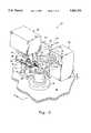
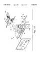
- FIG. 2is an isometric view of the testing apparatus of the invention illustrating the relative positions of the mechanical components
- FIG. 3is a top plan view of the testing apparatus shown in FIG. 2,
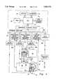
- FIG. 4is a block diagram schematic showing the operational control of the testing apparatus of FIGS. 2 and 3;
- FIG. 5is a schematic showing the geometrical relationships between the tester components and the magnetic disk
- FIG. 6is a flow diagram illustrating the algorithm used to direct the movements of the mechanical components of the testing apparatus shown in FIGS. 2-5;
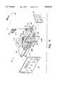
- FIG. 7is a side plan view of the testing apparatus of FIG. 2 having the disk stand and the linear servomechanism illustrated in ghost lines revealing the translational slide and the calibration assembly;
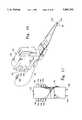
- FIG. 8is an isometric view of a first embodiment of an assembled rotatable arm
- FIG. 9is an exploded view of the rotatable arm shown in FIG. 8;
- FIG. 10is a magnetic head transfer assembly of the rotatable arm of FIGS. 8 and 9 illustrating the wiring of the magnetic head;
- FIG. 11is a rear plan view of the magnetic head transfer assembly shown in FIG. 10;
- FIG. 12is an isometric view of a second embodiment of an assembled rotatable arm
- FIG. 13is an exploded view of the rotatable arm shown in FIG. 12, illustrating a disengaged detachable module
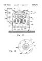
- FIG. 14is a exploded view of the detachable module shown FIGS. 12 and 13 illustrating the relevant parts of the detachable module;
- FIG. 15is an isometric view of a rotary wire connector
- FIG. 16is a top plan view of the rotary wire connector taken along line 16--16 of FIG. 15;
- FIG. 17is a front plan view of the rotary wire connector taken along line 17--17 of FIG. 15;
- FIG. 18is an end plan view of a plurality of cams mounted on the shaft of the wire connector of FIGS. 15-17;
- FIG. 19is a side plan view of a vertical slide of the testing apparatus of the invention.
- FIG. 20is a supplementary view taken from the dot-dash circle identified as 20 shown in FIG. 19;
- FIG. 21is a block diagram schematic of the amplifier of the testing apparatus of the invention.
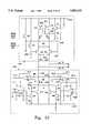
- FIG. 22is a circuit schematic of the linear current drive and the voltage feedback circuit shown in FIG. 21.
- FIGS. 2 and 3show the testing apparatus of the invention generally signified by reference numeral 22.
- reference numeral 22electrical wirings and circuit boards are removed in FIGS. 2 and 3.
- the electrical aspects of the testing apparatus 22will be described later in the specification.
- the testing apparatus 22includes a base 24 which comprises a rigid surface.
- a base 24which comprises a rigid surface.
- An exampleis a metal slab of sufficient rigidity and thickness.
- the base 24can be equipped with shock absorbing means (not shown).
- first translational means 26such as a translational slide 28 slidable on a stationary platform 27 in a linear direction signified by reference numeral 30.
- the linear movement of the slide 28is made possible by a stationary DC servo motor 35 driving a lead screw 37 through the slide 28.
- a linear servomechanism 32, directly coupled to the slide 28,is implemented for control of the linear movement of the slide 28, via a feedback assembly 34.
- a calibration assembly 29Adjacent to the slide 28 but fixedly mounted to the stationary platform 27 is a calibration assembly 29 having calibration screws 31A and 31B located at both ends.
- the calibration assembly 29is installed for the initial calibration of the linear servomechanism 32 prior to usage.
- a rotatable arm 36Pivotally attached to the translational slide 28 is a rotatable arm 36.
- the arm 36includes a proximal end 42 which is pivotally mounted to the slide 28 through a shaft 44, and a distal end 46 which is affixed with a magnetic head 48.
- a counterweight 50can be integrally attached to the proximal end 42 of the arm 36 for the purpose of stabilizing the rotational movement 40.
- a second translational means or elevating means 52Disposed between the magnetic head 48 and the distal end 42 of the rotatable arm 36 is a second translational means or elevating means 52, such as a vertical slide 54 which is movable in a vertical direction 56 (FIG. 2).
- the vertical slide 54includes a servomechanism 55 which allows the magnetic head 48 to be adjustably moved above the surface of a magnetic disk 58.
- a disk stand 60is fixedly installed on the top of the base 24.
- the disk stand 60comprises a stand base 62 carrying a revolvable spindle 64, which in turn is supporting the magnetic disk 58.
- FIG. 4is a block diagram showing the operational control of the testing apparatus 22.
- the main controlis a computer generally designated by the reference numeral 66.
- the computer 66can be a typical computer having a CPU 67 linked to a volatile memory, such as a RAM circuit 68 and a nonvolatile memory, such as a hard disk 70.
- the CPU 67is also tied to a peripheral interface circuit 72 which communicates with other circuits external to the computer 66 via an interface data bus 88. Human interaction with the computer is made possible through a keyboard 74 and a video monitor 76.
- the key mechanical components of the apparatus 22are operationally movable during the testing process.
- the slide 28is freely slidable in the direction 30, the rotatable arm 36 is freely rotatable in the direction 40, and the vertical slide 54 is movable in the direction 56 (FIGS. 2 and 3).
- the directions of movement 30, 40 and 56are all controlled by the respective servomechanisms 32, 38 and 55, which in turn are controlled by the respective interface circuits 78, 80 and 82.
- the amplifier circuit 84is controlled by the data interface circuit 86 which is linked to the interface data bus 88.
- variable datasuch as the required skew angles and the radial track distances
- specific testing routinescan be loaded from the nonvolatile memory 70 into the RAM 68, and the required testing processes would be executed automatically by the CPU 67.
- the resulting testing data sensed by the amplifier circuit 84are sent back to the CPU 67 via the data interface bus 88 for evaluation or for statistical analysis.
- FIG. 5shows the geometrical relationships of the translational slide 28 and the rotatable arm 36 with respect to the magnetic disk 58.
- the operational movements of the slide 28 and the arm 36 of the testing apparatus 22are herein described.
- each data trackis characterized by a skew angle a and a radial distance r, as explained above.
- the testing apparatus 22To simulate the real disk drive operation, the testing apparatus 22 must orientate the magnetic head 48 at the same skew angle ⁇ , and position the head 48 at the same radial distance r away from the center of the disk 19.
- the arm length A of the testing apparatus 22is different from the length of the real disk drive arm.
- the center of rotation 17 of the arm 36 of the tester 22is possibly located differently from that of the actual disk drive with respect to the disk center 19.
- the testing apparatus 22 of the inventionsolves these problems by automatically calculating the necessary translational distance y and the rotational angle ⁇ , based on the given geometry, in conjunction with the required skew angle a and the radial distance r. Once the values y and ⁇ are computed, the testing apparatus 22 translates the slide 22 at the distance y and rotates the arm 36 at the angle ⁇ and thereafter performs the testing.
- the calculations of the translational distance y and the rotational angle ⁇are performed by the computer 66 (FIG. 4).
- two mathematical expressionsmust first be derived, namely, the first and second expressions that define the translational distance y and the rotational angle ⁇ , respectively, as functions of the skew angle ⁇ , the radial distance r and the existent geometrical arrangement.
- FIG. 5shows an exemplary arrangement of the slide 28 and the rotatable arm 36 with respect to the magnetic disk 58.
- rradial distance of the magnetic head to the center of the magnetic disk
- Xseparation between the rotation center of the arm and the center of the magnetic disk along the x-direction
- ddistance between the rotation center of the arm and the center of the magnetic disk
- ⁇an arbitrary starting angle
- ⁇angle between the line joining the centers of the arm of rotatation and magnetic disk with respect to the y direction;
- Rthe perpendicular distance from the center of the arm rotation to the tip of the magnetic head
- Athe distance between the center of the arm rotation to the magnetic head
- ⁇ , ⁇ and ⁇are transitory angles.
- Equation (9)now reduces to a function dependent upon the skew angle ⁇ , the radial distance r and the fixed geometrical parameters of the apparatus 22.
- equation (10)also depends on the skew angle ⁇ , the radial distance r and the fixed geometrical parameters of the apparatus 22.
- Equations (9)-(12)can be programmed into the computer 66. Once the skew angle ⁇ and the radial distance r are entered, the computer 66 would calculate the sought after values y and ⁇ automatically.
- FIG. 6is a flow chart illustrating the algorithm used by the computer 66 to direct the testing apparatus 22 for the testing of each data track.
- ⁇g( ⁇ ,r) which basically includes equations (10)-(12).
- the CPU 67directs the motor interface circuit 206 via the interface data bus 88 to advance the translational slide 28 a distance y, as shown in block 21G.
- the CPU 67instructs the motor interface circuit 211 to rotate the rotatable arm 36 an angle ⁇ , as shown in block 21H.
- the magnetic headtranslates and rotates solely as a function of the radial distance or skew angle, respectively, but not both.
- designs of this typeplaces considerable restriction the mobility of the movable parts. This partly contribute to the substantial mounting and dismounting involvement during disk changes, and the stringent head alignment requirement prior to testing.
- the testing apparatus of the inventioninvolves no such inconvenience.
- FIG. 7Shown in FIG. 7 is a side plan view taken along line 7--7 of FIG. 2.
- the disk stand 60 and the linear servomechanism 32are shown in phantom lines, thereby revealing first translational means 26 unobstructed.
- first translational means 26 in this embodimentincludes a slide 28 slidably disposed atop the stationary platform 27.
- a trough 92(FIG. 3) having a pair of guide rails 90A and 90B upon which the slide 28 is slidably resting.
- a plurality of ball bearings 94Partially embedded inside the guide rails 90A and 90B is a plurality of ball bearings 94 which facilitate the linear movement 30 of the slide 28.
- the linear movement of the slide 28 in the direction 30is achieved by a DC servo 35 driving the lead screw 37 which engages the slide 28 through a nut 96 attached to the slide 28.
- the servo motor 35is fixedly attached to a bracket 98 which in turn is permanently anchored onto the stationary platform 27.
- the bracket 98is shown partially fragmentary to reveal a flexible coupler 100 connecting the motor shaft 102 and the lead screw 37.
- the flexible coupler 100corrects misalignment, reduces vibrations and enables a smoother rotational movement of the lead screw 37 at the distal end inside the slide 28.
- the lead screw 37spins along with the coupler 100 and the motor shaft 102.
- the screw 37 engaging the nut 96drives the slider 28 along the linear direction 30.
- the slide 28 illustrated in hidden lines shown in FIG. 7portrays an alternative position of the slide 28 glided along the rails 90A and 90B.
- extension plate 106(FIG. 7) which is attached to the rotational servomechanism 38.
- the extension plate 106is bolted onto the slide 28 via bolts 108A-108F.
- the rotational servomechanism 38is bolted onto the extension plate 106 through bolts 110A and 110B (FIG. 3).
- the rotational servomechanism 38 and the rotatable arm 36are connected together through the shaft 44.
- the motor (not shown) inside the rotational servomechanism 38carries and moves the arm 36 in the rotational direction 40 (FIG. 3). Arranged in this manner, the magnetic head 48 affixed to the distal end 46 of the arm 36 can traverse the magnetic disk 58 on the top of the disk stand 60.
- the linear feedback assembly 34is fixedly attached to the sidewall of the slide 28.
- the feedback assembly 34includes a laser reflector 112 and a reference extension 114.
- the calibration assembly 29, having calibration screws 31A and 31B,are also fixedly outrigged onto the stationary platform 27.
- the reflector 112, the extension 114, the calibration assembly 29 with the screws 31A and 31Bare installed for the purpose of calibrating the servomechanism 32 prior to usage.
- FIGS. 8 and 9show a first embodiment of the rotatable arm 36 in further detail.
- FIG. 8is an assembled drawing of the arm 36 and
- FIG. 9is an exploded view showing the relevant parts made up of the arm 36.
- the arm 36includes an arm body 116 having a proximal end 42 and a distal end 46. At the proximal end 42 is integrally attached a shaft coupler 118, which is coupled to a motor (not shown) inside the rotational servomechanism 38 for rotational movement.
- a counterweight portion 50can be integrally annexed to the proximal end 42 of the arm 36 to effectuate more balanced rotational movements.
- the upper flange 120Ais mounted to a lead screw housing 122 which encompasses a lead screw 126.
- the lead screw 126has one end engaging the vertical slide 54 and another end connected to a stepper motor 124.
- the motor 124spins the lead screw 126 which in turn drives the vertical slide 54 along the vertical direction 56.
- the magnetic head 48being affixed to the vertical slide 54, moves along with the slide 54 in the direction 56.
- another slidesimilar to the vertical slide 54, can also be assembled onto the lower flange 120B in a similar fashion carrying another magnetic head, such that two magnetic heads can interact with a double-sided magnetic disk.
- a release mechanism 128,which is installed for accommodating a head transfer assembly 130.
- the release mechanism 128comprises a lever 132 pivoted about a lead screw 126 behind a slide block 134.
- the lever 132is then pulled upwardly in the direction 138, thereby advancing the lead screw 126 and the slide block 134 toward the head transfer assembly 130.
- the tip of the screw(not shown) then penetrates into the opening 140 of the assembly 130, and coupled with the compressive force of the slide block 134 against the assembly 120, the head assembly 120 is tightly secured in place.
- the read-write amplifier 84can be proximally disposed adjacent to the head transfer assembly 130, such that sensed signals detected by the magnetic head 48 are amplified first before sending signals to other circuitries over a long distance for processing.
- the amplifier circuit 84is screwed onto the front part of the vertical slide 54. Arranged in this manner, the chance of noise contamination on the preliminarily sensed signal is substantially reduced.
- other circuitssuch as a high frequency buffering circuit 142, can be secured to the arm body 116 via screws 144A and 114B, and connectors 146A and 146B.
- Magnetic headsare fabricated at a miniaturized scale. Magnetic heads must also electrically communicate with other circuits displaced at a distance from the head in a tester. However, the wires leading to the magnetic heads are normally exceedingly small in diameter. Handling such wires in setting up the testing processes is a time-consuming and cumbersome endeavor.
- FIGS. 10 and 11show the wiring of the magnetic head 48 on the head transfer assembly 130.
- a magnetic head 48comprises a slider 148 carrying at least one transducer 150 at the slider edge.
- In an inductive headonly two wires would come out of the head 48.
- the wires 152 sourcing out from the head 48are soldered onto small paddle boards 154 which are insertable into receptacles 156.
- FIGS. 12-14show a second embodiment of the rotatable arm signified by reference numeral 36'.
- FIG. 12is an assembled drawing of the arm 36' and
- FIGS. 13 and 14are exploded views showing the relevant parts made up of the arm 36'.
- the shaft coupler 118is integrally affixed to the arm body 116 and the arm 36' has a distal end 46 and a proximal end 42.
- a counterweight portion 50can be joined to the proximal end 42 of the arm 36, for the purpose of balancing the rotational movement.
- FIGS. 12-14There are two flanges 120A and 120B integrally formed with the arm body 116. Shown in FIGS. 12-14 is the upper flange 120A attached to a lead screw housing 122 which encompasses a lead screw 126.
- the lead screw 126has one end engaging a vertical slide 54' and another end connected to a stepper motor 124. When energized, the rotational movement of the stepper motor 124 spins the lead screw 126, which in turn drives the vertical slide 54' in a linear movement along the vertical direction 56.
- another similar vertical slidesimilar to the slide 54', can also be assembled onto the lower flange 120B in a similar fashion carrying another magnetic head, such that two magnetic heads interact with a two-sided magnetic disk.
- the distinctive feature of the arm 36' of this embodiment compared to the arm 36 of the previous embodimentis a detachable module 160 which is herein described.
- FIG. 13shows the detachable module 160 that is releasably attached to the distal end 46 of the rotatable arm 36'.
- FIG. 14is an exploded view of the detachable module 160, exposing the constituent parts in additional detail.
- the module 160includes a module base 164 having hand grips 162A and 162B, and a pair of anchoring pins 166A and 166B (only one is shown in FIG. 14) insertable into the respective openings 169A and 169B formed in the vertical slide 54'.
- Atop the module base 164are an amplifier board 84', and a head transfer assembly 130'.
- the amplifier board 84'is attachable onto the module base 164 through a plurality of connector pins 168 insertable into openings 170 formed in the base 164.
- the head transfer assembly 130'is secured onto the base 164 via screws 172.
- the magnetic head 48is securely latched under the head transfer assembly 130' via a grip (not shown) controlled by a lever 167.
- a rotary wire connector 174disposed on the top of the amplifier board 84' via soldering or screws.
- the fully assembled detachable module 160is as shown in FIG. 12.
- the advantage of integrating the components in the form of a moduleis multifold. To begin with, tester downtime is significantly reduced.
- the module 160can be prepared and pre-wired before snapping onto the vertical slide 54'. There is no need to shut down the tester for magnetic head wiring, for example. In the event of repair or maintenance, the module 160 can be separately released without affecting the rest of the testing setup. Another pre-wired module 160 may be inserted as a replacement.
- the amplifier circuit 84'can be placed very close to the magnetic head 48 within the module 160. There is no need to extend long wirings from the magnetic head 48 to the amplifier circuit 84', thereby reducing the probability of noise occurrence.
- the rotary wire connector 174 shown in FIGS. 12-14is a device which is designed to alleviate the normally cumbersome wiring process.
- FIG. 15Shown in FIG. 15 is an enlarged perspective view of the connector 174.
- FIGS. 16 and 17are top and side views taken along line 16--16 and 17--17 of FIG. 15, respectively.
- the wire connector 174comprises a housing 176 having a plurality of wire openings 178A-178D. Springs 180A-180D are disposed inside the wire openings 178A-178D, respectively. Atop the housing 176 are a plurality of cams 182A-182D attached through a common shaft 180.
- the shaft 180passes through sleeves 184A and 184B (FIG. 16) integrally joined to the housing 176.
- At one end of the shaft 180is a thumb wheel 186 having indicating labels 188 marked thereon along the cylindrical wheel wall.
- a locking wheel 190having a plurality of hemispherical cavities 192 on the cylindrical wheel wall.
- the cavities 192 of the locking wheel 190engage a ball bearing 194 and a spring 196 inside the housing 176 (FIG. 17), thereby enabling the shaft 180 to rotatably move in discrete steps.
- a plurality of slots 198A-198Daccommodating a plurality of piano keys 200A-200D, respectively.
- the piano keys 200A-200Dare pivotally attached though a common pin 202 inside the respective slots 198A-198D.
- one endis pressed against one of the cams 182A-182D, and the other end is attached to one of the compression springs 180A-180D.
- FIG. 18is an end view of the shaft 180 passing through the eccentric cams 182A-182D.
- the shaft 180turns the eccentric cams 182A-182D simultaneously.
- the cams 182A-182Dcompress the piano keys 200A-200D one at a time, and accordingly stretch the compression springs 180A-180D one at a time, respectively.
- each of the springs 180A-180Dis stretched, bare wires can be inserted into spring windings in the respective openings 178A-178D for making electrical connections.
- the labeling 188 on the thumb wheel 186indicates which of the springs 180A-180D is stretched, thereby facilitating the process of wiring. When none of the springs are stretched, all the wires would be tightly trapped in place. With this arrangement, wiring of the thin wires associated with a magnetic head is no longer a time consuming or cumbersome task.
- paddle board openings 204A-204Dformed in the housing 176.
- paddle boards linking to the magnetic head wirescan be inserted into the openings 204A-204D, in lieu of the bare wire trapping in the springs 180A-180D. There are no fixture changes at all to make the transition.
- the servomechanisms 32 and 38are respectively Model 3070 and Model 3035 servo positioning systems manufactured by CMX corporation of Wallingford, Connecticut.
- Both servomechanisms 32 and 38utilize the wavelength of light emitting from the respective coherent light sources as the basis of displacement measurement.
- the servomechanisms 32 and 38employ optical interferometers.
- the principle of operation of the optical interferometersis herein briefly described.
- a Helium Neon (HeNe) laser diode Lemits a coherent light with wavelength of approximately 810 nm (nanometers) along a path P1 toward an internal light splitter S.
- HeNeHelium Neon
- the light splitter Sis essentially a partially silvered mirror allowing half of the light to pass through, that strikes an internal mirror Ml along a path P2 and reflects the other half which heads toward an external mirror M2 located inside the reflector 112 along a path P3.
- the split light raysare reflected.
- the reflected light rays from the mirrors M1 and M2 at the same timeare directed toward a target T along the paths P4 and P5, respectively.
- a light interference patternis formed on the target T which is an array of charge coupled devices.
- Different distances d of the mirror M2 disposed away from the servomechanism 32generate different interference patterns on the target T. Since the mirror M2 is fixedly attached to the slide 28, the precise location of the slide 28 along the stationary platform 27 can be ascertained by interpreting the interference pattern on the target T.
- the servomechanism 32Prior to usage, the servomechanism 32 needs to be calibrated.
- the calibration assembly 29having the two lead screws 31A and 31B performs this duty.
- the desired "home position" of the slide 28must first be determined. This is accomplished by first turning the screw 31B to a location intended as the home position.
- the calibration extension 114(also shown in FIG. 7) is then moved toward the calibration screw 31B until the extension 114 is in contact with the tip of the screw 31B.
- the extension 114is fixedly attached to the slide 28. Therefore the slide 28 must also move along with the extension 114 to the home position. This position is then registered into the computer 66 as the designated home position.
- the "end position" of the slide 28needs to be determined. This is achieved by placing a calibration block (not shown) of predetermined fixed length F between the tips of the screws 31A and 31B.
- the blockis normally made of a material which is temperature compensated. That is, the coefficient of thermal expansion of the calibration block does not vary much over the operational temperature range.
- the screw 31Ais then adjusted until both screws 31A and 31B snugly clamp the calibration block. Thereafter, the calibration block is removed.
- the slide 28then advances toward the screw 31A until the calibration extension 114 is in contact with the tip of screw 31A. This position is then registered into the computer 66 as the end position of the slide 28.
- any distance along the fixed distance Fcan be located via the calibrated servomechanism 32.
- the CPU 67 of the computer 66directs the motor interface circuit 206 to advance the lead screw 37 a calculated number of revolutions (FIG. 4).
- the calibrated servomechanism 32checks the advanced distance of the slide 28, in a manner as described above, against the inputted distance value. Should there be any discrepancies between the two values, the servomechanism 32 requests the CPU 67 to provide necessary corrections via the translational servomechanism interface circuit 78.
- the above described processrepeats itself several times until an acceptable displacement tolerance is reached. In the preferred embodiment, the resolution of displacement of the slider 28 is accurate within a range of 6.33 nm.
- the principle of operationis similar except rotational displacements are used to generate light interference patterns.
- the calibration assemblyin the form of angular internal stops is located inside the housing. Once the angular home position is determined, the rotational servomechanism 34 can be operated in the same manner as the linear servomechanism 32 as described above. For the sake of conciseness, the operational detail of the rotational servomechanism 34 is not further elaborated.
- the angular resolution of the rotatable arm in the preferred embodimentis accurate within a range of 0.125 ⁇ radians.
- FIG. 19shows a side plan view of the distal end 46 of the rotatable arm 36.
- the lead screw housing 122is fixedly attached to the flange 120A which is stationary with respect the arm body 116.
- the stepper motor 124which drives the lead screw 126 inside the housing 122.
- the lead screw 126engages a nut 212 held by a bracket 214 fixedly secured on the back side of the vertical slide 54.
- the stepper motor 124is capable of driving the vertical slide in a vertical direction 56 relative to the arm body 116.
- FIG. 20is a supplementary view taken from the dot-dash line circle identified as 20 shown in FIG. 19, showing the tip portion of the sensor finger 214 and the magnetic head 48 at a larger scale.
- the magnetic disk 58is basically made of metal and is normally tied to ground potential.
- the thin metal layer 218 and the surface 220 of the magnetic disk 58form an electrical capacitor with the metal layer 218 and the disk surface 220 acting as capacitor electrodes.
- capacitance valueis inversely proportional to the distance between the electrodes.
- the electrode distanceis the displacement of the metal film 218 with respect to the disk surface 220. This distance is defined as the Z-height Z of the tester 22.
- the Z-height Zshould be distinguishable from the flying height h of the slider 148 above the disk surface 220.
- the flying height h of the slider 148is dependent upon a number of aerodynamic parameters while the disk 58 is in spinning motion.
- the flying height his related to the Z-height Z, which is essentially an arbitrary fixed reference point at the vertical slide 54 with respect to the disk surface 220.
- the Z-height Zis defined as the distance between the sensing metal film 218 and the disk surface 220.
- a home position as referenceneeds first to be designated. Once the home position is determined, any distance above the disk surface 220 can be ascertained by evaluating the capacitance value formed between the metal film 218 and the metal disk 58. For example, suppose the vertical slide 54 needs to be positioned at a certain distance above the disk surface 220. This distance is fed into the computer 66. The CPU 67 of the computer 66 directs the motor interface circuit 220 to activate the motor 124 which in turn spins the lead screw 126 a calculated number of revolutions.
- the lead screw 126engages the nut 212 and moves the vertical slide 54 to the intended distance above the disk surface 220.
- the Z-height servomechanism interface circuit 82checks the capacitance value of the metal film 218 and the disk 58 at that particular location, and thereafter translates the capacitance value into a linear distance. Should there be any discrepancies between the inputted value and the detected value, the servomechanism 82 requests the CPU 67 to provide necessary corrections via the motor interface circuit 220.
- the above described processrepeats itself several times until an acceptable tolerance is reached. In the preferred embodiment, the resolution of displacement of the vertical slider 54 is accurate within a range of 6.33 nm.
- FIG. 21which is an electrical block diagram of the amplifier circuit 84 or 84' mentioned previously, depicts the amplifier circuit 84 or 84' that can be partitioned into an inductive head circuit portion 224 and a magnetoresistive (MR) head circuit portion 226. Either one or all of the circuit portions 224 and 226 can be used during normal operation depending on applications.
- MRmagnetoresistive
- the inductive head circuit portion 224can be further divided into a data writing section 228 and a data reading section 230.
- the data writing section 228includes a multiplier 232 driving a linear current drive 234 which is linked to an inductive head 236 through a plurality of switches 238A-238D.
- the feedback circuitis coupled between the inductive head 236 and the linear current driver 234.
- the data reading section 230includes a variable gain amplifier 242 tied to the inductive head 236.
- the magnetoresistive head circuit portion 226comprises another variable gain amplifier 244 connected to an MR head 246. There is also a bias current source 248 attached to the MR head 246 to provide bias current to the head 246 for orienting the head 246 into the proper operating region.
- the multiplier 232is a discrete component having a part number AD834, manufactured by Analog Devices, Inc. of Wilmington, Mass.
- the variable gain amplifier 242is another discrete component having a part number NE/DA5209, manufactured by Philips Semiconductor of Eindhoven, the Netherlands.
- the detailed schematic of the linear current driver 234 and the voltage feedback circuit 240are shown in FIG. 22. These two circuits are herein depicted along with the operational description of the inductive head circuit portion 224.
- the read/write select input R/Wis first activated.
- a high signal applied at the input R/Wcloses electrical switches 238A, 238C, 238E and 238H.
- Write data in true and complementary versionsare then applied to the write data input WD and the write data complementary input WD, respectively.
- only the true version of the write datathat is, without the complementary version, can be supplied to the multiplier 232.
- a DC voltage levelis also tied to the write control input WC.
- a multiplieraccepts multiple input signals and generates output signals as a product of the corresponding input signals. In this case, the output voltages V O and V CO of the multiplier 232 are made available at nodes 250 and 252, respectively, in accordance with the following equations:
- V WD and V WCare the voltages at the inputs WD and WC respectively
- Kis a multiplier constant which is a function of the circuit parameters of the multiplier circuit 232 and is adjustable. Any type of logic levels, irrespective of whether the input signals are Emitter-Coupled Logic (ECL) or Transistor-Transistor Logic (TTL), can be applied to the amplifier circuit 84 or 84' via the inputs WD and WD. The reason is because the DC voltage level at the write control input WC can scale the input signals via the multiplier 232 in accordance with the above mentioned equations (13) and (14) into proper voltage levels at the multiplier outputs 250 and 252 before processing.
- ECLEmitter-Coupled Logic
- TTLTransistor-Transistor Logic
- FIG. 22shows the internal structures of the linear current drive 234 and the voltage feedback circuit 240.
- the linear current drive 234is essentially a differential amplifier 254 having an assertive circuit portion 255 which includes a transistor Q4, and a complementary circuit portion 257 which comprises a transistor Q5.
- a first voltage reference source 256having a transistor Q1 and the resistors R1 and R2, is also installed adjacent to the differential amplifier 254. Current flowing through resistors R1 and R2 and the base-emitter junction of the transistor Q1 establishes a fixed voltage at the emitter node 258 of the transistor Q1. As a result, the voltage levels at the base-emitter junctions of transistors Q2 and Q3 are also fixed, yielding fixed collector currents I1 and I2, respectively.
- transistors Q2 and Q3here act as dual current sources, namely, first and second current sources 259 and 261.
- Currents I1 and I2 from the first and second current sources 259 and 261, respectively,will proportionally steer into the transistors Q4 and Q5, depending on the respective base-emitter voltages of these two transistors.
- This feature of having double current sources 259 and 261significantly increases the linear amplification range of the current drive 234.
- the differential amplifier 254in which the base-emitter voltages of the transistor Q4 and Q5 are controlled by the multiplier outputs 250 and 252 through emitter follower transistors Q6 and Q7, respectively.
- the voltages at nodes 262 and 260would follow the voltages at nodes 250 and 252 with the corresponding base-emitter junction drops of transistors Q6 and Q7, respectively.
- the transistor Q5With the voltage potential at the base of transistor Q5 lower than that of the transistor Q4, the transistor Q5 is more actively turned on in comparison to the transistor Q4.
- a second voltage reference source 264comprising a transistor Q8 and resistors R4 and R5, and a third voltage reference source 266 including a transistor Q9 and resistors R6 and R7.
- the voltages at the base-emitter junctions of transistors Q10 and Q11are also determined by the emitter voltages of the transistors Q8 and Q9, respectively, yielding corresponding collector currents I5 and I6, respectively.
- the voltage potentials at the bases of the transistors Q8 and Q9are not constant. Instead, these base potentials are dependent on the outputs of the first and second feedback amplifier stages 268 and 270, respectively, which are in turn driven by third and fourth feedback amplifier stages 272 and 274, respectively.
- the voltage potential at the base of the transistor Q11is consequently higher in value than the corresponding base voltage potential for the transistor Q10.
- the transistor Q11is therefore more actively turned on than the transistor Q10. That is, the collector current I6 is higher than the collector current I5. Therefore, the current direction for I4 shown in FIG. 22 should be reversed, or alternatively, the current value of the current I4 is negative.
- These push and pull actions of the currents I3 and I4constitute the write current injecting into the inductive magnetic head 236 (FIG. 21).
- the voltage feedback circuit 240also serves the regulating function of stabilizing the write current into the inductive magnetic head 236.
- the degree of feedbackcan be predetermined by adjusting the ohmic values of the resistors R11 and R12 in the third amplifier stage 272, and R13 and R14 in the fourth amplifier stage 274.
- the testing apparatus of the present inventionprovides the advantages of allowing fast testing setup changes and adjustments, minimizing human intervention and machine downtime, and equally as important, accuracy. All are of critical importance to production environments requiring high testing throughput.
- the servomechanisms 32 and 38need not be optical interferometers. Other feedback mechanisms, such as systems employing acoustics, can well be used as substitutes.
- the vertical servomechanism 52need not be the type involving capacitance sensing.
- an optical interferometercan take its place.
- the detachable module 160need not be releasably latched onto the vertical slide 54' through hand grips 162A and 162B.
- the detachable module 160can well be attached to the vertical slide by other methods such as through screws, fastening or various other latching mechanisms.
- the cams 182A-182Dcan be fully encased within the housing 176.
- cams 182A-182Dneed not be circular, and the cams can have other shapes such as elliptical.
- other types of transistorssuch as complementary-metal-oxide-silicon (CMOS) transistors, can replace the bipolar transistors with minor circuit modification.
- CMOScomplementary-metal-oxide-silicon
Landscapes
- Supporting Of Heads In Record-Carrier Devices (AREA)
Abstract
Description
V.sub.O =K×V.sub.WD ×V.sub.Wc (13)
V.sub.CO =-(K×V.sub.WD ×V.sub.WC) (14)
Claims (45)
Priority Applications (2)
| Application Number | Priority Date | Filing Date | Title |
|---|---|---|---|
| US08/544,090US5801531A (en) | 1996-01-18 | 1996-01-18 | Apparatus and method for testing magnetic heads using translational slides and a rotatable arm |
| US09/078,003US6099362A (en) | 1996-01-18 | 1998-05-13 | Apparatus and method for testing magnetic disk drive components |
Applications Claiming Priority (1)
| Application Number | Priority Date | Filing Date | Title |
|---|---|---|---|
| US08/544,090US5801531A (en) | 1996-01-18 | 1996-01-18 | Apparatus and method for testing magnetic heads using translational slides and a rotatable arm |
Related Child Applications (1)
| Application Number | Title | Priority Date | Filing Date |
|---|---|---|---|
| US09/078,003DivisionUS6099362A (en) | 1996-01-18 | 1998-05-13 | Apparatus and method for testing magnetic disk drive components |
Publications (1)
| Publication Number | Publication Date |
|---|---|
| US5801531Atrue US5801531A (en) | 1998-09-01 |
Family
ID=24170708
Family Applications (2)
| Application Number | Title | Priority Date | Filing Date |
|---|---|---|---|
| US08/544,090Expired - LifetimeUS5801531A (en) | 1996-01-18 | 1996-01-18 | Apparatus and method for testing magnetic heads using translational slides and a rotatable arm |
| US09/078,003Expired - Fee RelatedUS6099362A (en) | 1996-01-18 | 1998-05-13 | Apparatus and method for testing magnetic disk drive components |
Family Applications After (1)
| Application Number | Title | Priority Date | Filing Date |
|---|---|---|---|
| US09/078,003Expired - Fee RelatedUS6099362A (en) | 1996-01-18 | 1998-05-13 | Apparatus and method for testing magnetic disk drive components |
Country Status (1)
| Country | Link |
|---|---|
| US (2) | US5801531A (en) |
Cited By (20)
| Publication number | Priority date | Publication date | Assignee | Title |
|---|---|---|---|---|
| US6229303B1 (en)* | 1998-03-19 | 2001-05-08 | Guzik Technical Enterprises | Spinstand for testing magnetic heads and disks |
| US6293135B1 (en)* | 1997-07-25 | 2001-09-25 | Seagate Technology Llc | Method of calibrating a system for detecting contact of a glide head with a recording media surface |
| US6344738B1 (en)* | 2000-01-24 | 2002-02-05 | International Business Machines Corporation | Non-magnetic system for a memory disk test system |
| US6483300B1 (en)* | 2000-02-08 | 2002-11-19 | Seagate Technology Llc | Spin-stand having a disc heater |
| US6510752B1 (en) | 1999-02-22 | 2003-01-28 | Seagate Technology Llc | Method and apparatus for testing microactuators on a suspension assembly |
| US6538838B1 (en) | 1999-02-22 | 2003-03-25 | Seagate Technology Llc | Method and apparatus for closed-loop spin-stand testing |
| US20030193734A1 (en)* | 2002-04-16 | 2003-10-16 | Seing Hong S. | Apparatus and method for dynamic fly height adjustment |
| US20040130320A1 (en)* | 2002-09-18 | 2004-07-08 | Nahum Guzik | Magnetic head and disk X-Y test assembly with optimized arrangement for skew angle |
| US8218256B1 (en) | 2009-10-30 | 2012-07-10 | Western Digital Technologies, Inc. | Disk spindle assembly cartridge |
| US8270118B1 (en) | 2009-10-30 | 2012-09-18 | Western Digital Technologies, Inc. | Head stack assembly cartridge |
| US8432630B1 (en) | 2010-06-30 | 2013-04-30 | Western Digital Technologies, Inc. | Disk drive component test system |
| WO2016037597A1 (en) | 2014-09-09 | 2016-03-17 | Balluff Gmbh | Sensor element of an inductive proximity or distance sensor, and method for operating the sensor element |
| US20160284369A1 (en)* | 2015-03-25 | 2016-09-29 | Guzik Technical Enterprises | Head gimbal assembly (hga) support cartridge for magnetic head and disk testers |
| US11348611B1 (en) | 2021-04-19 | 2022-05-31 | Seagate Technology Llc | Zero skew elevator system |
| US11361787B1 (en) | 2021-07-30 | 2022-06-14 | Seagate Technology Llc | Zero skew disk drive with dual actuators |
| US11430472B1 (en) | 2021-11-17 | 2022-08-30 | Seagate Technology Llc | Triple magnet linear actuator motor |
| US11468909B1 (en) | 2021-11-02 | 2022-10-11 | Seagate Technology Llc | Zero skew with ultrasonic piezoelectric swing suspension |
| US11488624B1 (en) | 2021-09-20 | 2022-11-01 | Seagate Technology Llc | Ball bearing cartridge for linear actuator |
| US11581402B2 (en) | 2018-09-05 | 2023-02-14 | Board Of Regents, The University Of Texas System | Lateral semiconductor device and method of manufacture |
| US11948612B2 (en) | 2021-04-19 | 2024-04-02 | Seagate Technology Llc | Zero skew elevator system |
Families Citing this family (133)
| Publication number | Priority date | Publication date | Assignee | Title |
|---|---|---|---|---|
| WO2002027887A1 (en)* | 2000-09-27 | 2002-04-04 | Seagate Technology Llc | Automated drive-level microtrack profile using variable gain amplifier |
| US8689430B1 (en) | 2006-11-29 | 2014-04-08 | Western Digital (Fremont), Llc | Method for providing a perpendicular magnetic recording (PMR)head |
| US7543884B2 (en)* | 2007-10-30 | 2009-06-09 | Ford Motor Company | Clam shell bracket connecting automotive structural members |
| US8404128B1 (en) | 2009-02-23 | 2013-03-26 | Western Digital (Fremont), Llc | Method and system for providing a perpendicular magnetic recording head |
| US8400731B1 (en) | 2009-04-19 | 2013-03-19 | Western Digital (Fremont), Llc | Write head with variable side shield gaps |
| US8611055B1 (en) | 2009-07-31 | 2013-12-17 | Western Digital (Fremont), Llc | Magnetic etch-stop layer for magnetoresistive read heads |
| US9202480B2 (en) | 2009-10-14 | 2015-12-01 | Western Digital (Fremont), LLC. | Double patterning hard mask for damascene perpendicular magnetic recording (PMR) writer |
| US8441896B2 (en) | 2010-06-25 | 2013-05-14 | Western Digital (Fremont), Llc | Energy assisted magnetic recording head having laser integrated mounted to slider |
| US8997832B1 (en) | 2010-11-23 | 2015-04-07 | Western Digital (Fremont), Llc | Method of fabricating micrometer scale components |
| US8441756B1 (en) | 2010-12-16 | 2013-05-14 | Western Digital (Fremont), Llc | Method and system for providing an antiferromagnetically coupled writer |
| US9123359B1 (en) | 2010-12-22 | 2015-09-01 | Western Digital (Fremont), Llc | Magnetic recording transducer with sputtered antiferromagnetic coupling trilayer between plated ferromagnetic shields and method of fabrication |
| US8456961B1 (en) | 2011-03-22 | 2013-06-04 | Western Digital (Fremont), Llc | Systems and methods for mounting and aligning a laser in an electrically assisted magnetic recording assembly |
| US8614882B2 (en)* | 2011-06-21 | 2013-12-24 | International Business Machines Corporation | Card connector with a servomechanical device for repositioning an expansion card |
| US8419954B1 (en) | 2011-10-31 | 2013-04-16 | Western Digital (Fremont), Llc | Method for providing a side shield for a magnetic recording transducer |
| US8760823B1 (en) | 2011-12-20 | 2014-06-24 | Western Digital (Fremont), Llc | Method and system for providing a read transducer having soft and hard magnetic bias structures |
| US8451563B1 (en) | 2011-12-20 | 2013-05-28 | Western Digital (Fremont), Llc | Method for providing a side shield for a magnetic recording transducer using an air bridge |
| US9093639B2 (en) | 2012-02-21 | 2015-07-28 | Western Digital (Fremont), Llc | Methods for manufacturing a magnetoresistive structure utilizing heating and cooling |
| US9349392B1 (en) | 2012-05-24 | 2016-05-24 | Western Digital (Fremont), Llc | Methods for improving adhesion on dielectric substrates |
| US8724259B1 (en) | 2012-06-11 | 2014-05-13 | Western Digital (Fremont), Llc | Conformal high moment side shield seed layer for perpendicular magnetic recording writer |
| US9269382B1 (en) | 2012-06-29 | 2016-02-23 | Western Digital (Fremont), Llc | Method and system for providing a read transducer having improved pinning of the pinned layer at higher recording densities |
| US8711528B1 (en) | 2012-06-29 | 2014-04-29 | Western Digital (Fremont), Llc | Tunnel magnetoresistance read head with narrow shield-to-shield spacing |
| US9213322B1 (en) | 2012-08-16 | 2015-12-15 | Western Digital (Fremont), Llc | Methods for providing run to run process control using a dynamic tuner |
| US8984740B1 (en) | 2012-11-30 | 2015-03-24 | Western Digital (Fremont), Llc | Process for providing a magnetic recording transducer having a smooth magnetic seed layer |
| US9053719B2 (en) | 2012-11-30 | 2015-06-09 | Western Digital (Fremont), Llc | Magnetoresistive sensor for a magnetic storage system read head, and fabrication method thereof |
| US8980109B1 (en) | 2012-12-11 | 2015-03-17 | Western Digital (Fremont), Llc | Method for providing a magnetic recording transducer using a combined main pole and side shield CMP for a wraparound shield scheme |
| US8760818B1 (en) | 2013-01-09 | 2014-06-24 | Western Digital (Fremont), Llc | Systems and methods for providing magnetic storage elements with high magneto-resistance using heusler alloys |
| US9042208B1 (en) | 2013-03-11 | 2015-05-26 | Western Digital Technologies, Inc. | Disk drive measuring fly height by applying a bias voltage to an electrically insulated write component of a head |
| US8883017B1 (en) | 2013-03-12 | 2014-11-11 | Western Digital (Fremont), Llc | Method and system for providing a read transducer having seamless interfaces |
| US9336814B1 (en) | 2013-03-12 | 2016-05-10 | Western Digital (Fremont), Llc | Inverse tapered waveguide for use in a heat assisted magnetic recording head |
| US9013836B1 (en) | 2013-04-02 | 2015-04-21 | Western Digital (Fremont), Llc | Method and system for providing an antiferromagnetically coupled return pole |
| US9111564B1 (en) | 2013-04-02 | 2015-08-18 | Western Digital (Fremont), Llc | Magnetic recording writer having a main pole with multiple flare angles |
| US9104107B1 (en) | 2013-04-03 | 2015-08-11 | Western Digital (Fremont), Llc | DUV photoresist process |
| US8993217B1 (en) | 2013-04-04 | 2015-03-31 | Western Digital (Fremont), Llc | Double exposure technique for high resolution disk imaging |
| US9245545B1 (en) | 2013-04-12 | 2016-01-26 | Wester Digital (Fremont), Llc | Short yoke length coils for magnetic heads in disk drives |
| US9064527B1 (en) | 2013-04-12 | 2015-06-23 | Western Digital (Fremont), Llc | High order tapered waveguide for use in a heat assisted magnetic recording head |
| US9070381B1 (en) | 2013-04-12 | 2015-06-30 | Western Digital (Fremont), Llc | Magnetic recording read transducer having a laminated free layer |
| US9431047B1 (en) | 2013-05-01 | 2016-08-30 | Western Digital (Fremont), Llc | Method for providing an improved AFM reader shield |
| US9064528B1 (en) | 2013-05-17 | 2015-06-23 | Western Digital Technologies, Inc. | Interferometric waveguide usable in shingled heat assisted magnetic recording in the absence of a near-field transducer |
| US9431039B1 (en) | 2013-05-21 | 2016-08-30 | Western Digital (Fremont), Llc | Multiple sensor array usable in two-dimensional magnetic recording |
| US9263067B1 (en) | 2013-05-29 | 2016-02-16 | Western Digital (Fremont), Llc | Process for making PMR writer with constant side wall angle |
| US9361913B1 (en) | 2013-06-03 | 2016-06-07 | Western Digital (Fremont), Llc | Recording read heads with a multi-layer AFM layer methods and apparatuses |
| US9406331B1 (en) | 2013-06-17 | 2016-08-02 | Western Digital (Fremont), Llc | Method for making ultra-narrow read sensor and read transducer device resulting therefrom |
| US9287494B1 (en) | 2013-06-28 | 2016-03-15 | Western Digital (Fremont), Llc | Magnetic tunnel junction (MTJ) with a magnesium oxide tunnel barrier |
| US9318130B1 (en) | 2013-07-02 | 2016-04-19 | Western Digital (Fremont), Llc | Method to fabricate tunneling magnetic recording heads with extended pinned layer |
| US8947985B1 (en) | 2013-07-16 | 2015-02-03 | Western Digital (Fremont), Llc | Heat assisted magnetic recording transducers having a recessed pole |
| US8923102B1 (en) | 2013-07-16 | 2014-12-30 | Western Digital (Fremont), Llc | Optical grating coupling for interferometric waveguides in heat assisted magnetic recording heads |
| US9431032B1 (en) | 2013-08-14 | 2016-08-30 | Western Digital (Fremont), Llc | Electrical connection arrangement for a multiple sensor array usable in two-dimensional magnetic recording |
| US9275657B1 (en) | 2013-08-14 | 2016-03-01 | Western Digital (Fremont), Llc | Process for making PMR writer with non-conformal side gaps |
| US9042051B2 (en) | 2013-08-15 | 2015-05-26 | Western Digital (Fremont), Llc | Gradient write gap for perpendicular magnetic recording writer |
| US9343098B1 (en) | 2013-08-23 | 2016-05-17 | Western Digital (Fremont), Llc | Method for providing a heat assisted magnetic recording transducer having protective pads |
| US9343086B1 (en) | 2013-09-11 | 2016-05-17 | Western Digital (Fremont), Llc | Magnetic recording write transducer having an improved sidewall angle profile |
| US9441938B1 (en) | 2013-10-08 | 2016-09-13 | Western Digital (Fremont), Llc | Test structures for measuring near field transducer disc length |
| US9042058B1 (en) | 2013-10-17 | 2015-05-26 | Western Digital Technologies, Inc. | Shield designed for middle shields in a multiple sensor array |
| US9349394B1 (en) | 2013-10-18 | 2016-05-24 | Western Digital (Fremont), Llc | Method for fabricating a magnetic writer having a gradient side gap |
| US9007719B1 (en) | 2013-10-23 | 2015-04-14 | Western Digital (Fremont), Llc | Systems and methods for using double mask techniques to achieve very small features |
| US9214172B2 (en) | 2013-10-23 | 2015-12-15 | Western Digital (Fremont), Llc | Method of manufacturing a magnetic read head |
| US8988812B1 (en) | 2013-11-27 | 2015-03-24 | Western Digital (Fremont), Llc | Multi-sensor array configuration for a two-dimensional magnetic recording (TDMR) operation |
| US9194692B1 (en) | 2013-12-06 | 2015-11-24 | Western Digital (Fremont), Llc | Systems and methods for using white light interferometry to measure undercut of a bi-layer structure |
| US9280990B1 (en) | 2013-12-11 | 2016-03-08 | Western Digital (Fremont), Llc | Method for fabricating a magnetic writer using multiple etches |
| US9001628B1 (en) | 2013-12-16 | 2015-04-07 | Western Digital (Fremont), Llc | Assistant waveguides for evaluating main waveguide coupling efficiency and diode laser alignment tolerances for hard disk |
| US9082423B1 (en) | 2013-12-18 | 2015-07-14 | Western Digital (Fremont), Llc | Magnetic recording write transducer having an improved trailing surface profile |
| US8917581B1 (en) | 2013-12-18 | 2014-12-23 | Western Digital Technologies, Inc. | Self-anneal process for a near field transducer and chimney in a hard disk drive assembly |
| US8971160B1 (en) | 2013-12-19 | 2015-03-03 | Western Digital (Fremont), Llc | Near field transducer with high refractive index pin for heat assisted magnetic recording |
| US9147408B1 (en) | 2013-12-19 | 2015-09-29 | Western Digital (Fremont), Llc | Heated AFM layer deposition and cooling process for TMR magnetic recording sensor with high pinning field |
| US8970988B1 (en) | 2013-12-31 | 2015-03-03 | Western Digital (Fremont), Llc | Electric gaps and method for making electric gaps for multiple sensor arrays |
| US9305583B1 (en) | 2014-02-18 | 2016-04-05 | Western Digital (Fremont), Llc | Method for fabricating a magnetic writer using multiple etches of damascene materials |
| US9183854B2 (en) | 2014-02-24 | 2015-11-10 | Western Digital (Fremont), Llc | Method to make interferometric taper waveguide for HAMR light delivery |
| US9142233B1 (en) | 2014-02-28 | 2015-09-22 | Western Digital (Fremont), Llc | Heat assisted magnetic recording writer having a recessed pole |
| US9396743B1 (en) | 2014-02-28 | 2016-07-19 | Western Digital (Fremont), Llc | Systems and methods for controlling soft bias thickness for tunnel magnetoresistance readers |
| US9202493B1 (en) | 2014-02-28 | 2015-12-01 | Western Digital (Fremont), Llc | Method of making an ultra-sharp tip mode converter for a HAMR head |
| US8988825B1 (en) | 2014-02-28 | 2015-03-24 | Western Digital (Fremont, LLC | Method for fabricating a magnetic writer having half-side shields |
| US9001467B1 (en) | 2014-03-05 | 2015-04-07 | Western Digital (Fremont), Llc | Method for fabricating side shields in a magnetic writer |
| US9153255B1 (en) | 2014-03-05 | 2015-10-06 | Western Digital (Fremont), Llc | Method for fabricating a magnetic writer having an asymmetric gap and shields |
| US9135930B1 (en) | 2014-03-06 | 2015-09-15 | Western Digital (Fremont), Llc | Method for fabricating a magnetic write pole using vacuum deposition |
| US9934811B1 (en) | 2014-03-07 | 2018-04-03 | Western Digital (Fremont), Llc | Methods for controlling stray fields of magnetic features using magneto-elastic anisotropy |
| US9190085B1 (en) | 2014-03-12 | 2015-11-17 | Western Digital (Fremont), Llc | Waveguide with reflective grating for localized energy intensity |
| US9111558B1 (en) | 2014-03-14 | 2015-08-18 | Western Digital (Fremont), Llc | System and method of diffractive focusing of light in a waveguide |
| US9135937B1 (en) | 2014-05-09 | 2015-09-15 | Western Digital (Fremont), Llc | Current modulation on laser diode for energy assisted magnetic recording transducer |
| US8953422B1 (en) | 2014-06-10 | 2015-02-10 | Western Digital (Fremont), Llc | Near field transducer using dielectric waveguide core with fine ridge feature |
| US9007879B1 (en) | 2014-06-10 | 2015-04-14 | Western Digital (Fremont), Llc | Interfering near field transducer having a wide metal bar feature for energy assisted magnetic recording |
| US8958272B1 (en) | 2014-06-10 | 2015-02-17 | Western Digital (Fremont), Llc | Interfering near field transducer for energy assisted magnetic recording |
| US8976635B1 (en) | 2014-06-10 | 2015-03-10 | Western Digital (Fremont), Llc | Near field transducer driven by a transverse electric waveguide for energy assisted magnetic recording |
| US9508363B1 (en) | 2014-06-17 | 2016-11-29 | Western Digital (Fremont), Llc | Method for fabricating a magnetic write pole having a leading edge bevel |
| US9361914B1 (en) | 2014-06-18 | 2016-06-07 | Western Digital (Fremont), Llc | Magnetic sensor with thin capping layer |
| US9214169B1 (en) | 2014-06-20 | 2015-12-15 | Western Digital (Fremont), Llc | Magnetic recording read transducer having a laminated free layer |
| US9053735B1 (en) | 2014-06-20 | 2015-06-09 | Western Digital (Fremont), Llc | Method for fabricating a magnetic writer using a full-film metal planarization |
| US9042052B1 (en) | 2014-06-23 | 2015-05-26 | Western Digital (Fremont), Llc | Magnetic writer having a partially shunted coil |
| US9230565B1 (en) | 2014-06-24 | 2016-01-05 | Western Digital (Fremont), Llc | Magnetic shield for magnetic recording head |
| US9190079B1 (en) | 2014-09-22 | 2015-11-17 | Western Digital (Fremont), Llc | Magnetic write pole having engineered radius of curvature and chisel angle profiles |
| US9007725B1 (en) | 2014-10-07 | 2015-04-14 | Western Digital (Fremont), Llc | Sensor with positive coupling between dual ferromagnetic free layer laminates |
| US9087527B1 (en) | 2014-10-28 | 2015-07-21 | Western Digital (Fremont), Llc | Apparatus and method for middle shield connection in magnetic recording transducers |
| US9786301B1 (en) | 2014-12-02 | 2017-10-10 | Western Digital (Fremont), Llc | Apparatuses and methods for providing thin shields in a multiple sensor array |
| US9721595B1 (en) | 2014-12-04 | 2017-08-01 | Western Digital (Fremont), Llc | Method for providing a storage device |
| US9111550B1 (en) | 2014-12-04 | 2015-08-18 | Western Digital (Fremont), Llc | Write transducer having a magnetic buffer layer spaced between a side shield and a write pole by non-magnetic layers |
| US9236560B1 (en) | 2014-12-08 | 2016-01-12 | Western Digital (Fremont), Llc | Spin transfer torque tunneling magnetoresistive device having a laminated free layer with perpendicular magnetic anisotropy |
| US9881638B1 (en) | 2014-12-17 | 2018-01-30 | Western Digital (Fremont), Llc | Method for providing a near-field transducer (NFT) for a heat assisted magnetic recording (HAMR) device |
| US9286919B1 (en) | 2014-12-17 | 2016-03-15 | Western Digital (Fremont), Llc | Magnetic writer having a dual side gap |
| US9214165B1 (en) | 2014-12-18 | 2015-12-15 | Western Digital (Fremont), Llc | Magnetic writer having a gradient in saturation magnetization of the shields |
| US9741366B1 (en) | 2014-12-18 | 2017-08-22 | Western Digital (Fremont), Llc | Method for fabricating a magnetic writer having a gradient in saturation magnetization of the shields |
| US10074387B1 (en) | 2014-12-21 | 2018-09-11 | Western Digital (Fremont), Llc | Method and system for providing a read transducer having symmetric antiferromagnetically coupled shields |
| US9343087B1 (en) | 2014-12-21 | 2016-05-17 | Western Digital (Fremont), Llc | Method for fabricating a magnetic writer having half shields |
| US9437251B1 (en) | 2014-12-22 | 2016-09-06 | Western Digital (Fremont), Llc | Apparatus and method having TDMR reader to reader shunts |
| US9449625B1 (en) | 2014-12-24 | 2016-09-20 | Western Digital (Fremont), Llc | Heat assisted magnetic recording head having a plurality of diffusion barrier layers |
| US9123374B1 (en) | 2015-02-12 | 2015-09-01 | Western Digital (Fremont), Llc | Heat assisted magnetic recording writer having an integrated polarization rotation plate |
| US9312064B1 (en) | 2015-03-02 | 2016-04-12 | Western Digital (Fremont), Llc | Method to fabricate a magnetic head including ion milling of read gap using dual layer hard mask |
| US9431031B1 (en) | 2015-03-24 | 2016-08-30 | Western Digital (Fremont), Llc | System and method for magnetic transducers having multiple sensors and AFC shields |
| US9443541B1 (en) | 2015-03-24 | 2016-09-13 | Western Digital (Fremont), Llc | Magnetic writer having a gradient in saturation magnetization of the shields and return pole |
| US9384763B1 (en) | 2015-03-26 | 2016-07-05 | Western Digital (Fremont), Llc | Dual free layer magnetic reader having a rear bias structure including a soft bias layer |
| US9449621B1 (en) | 2015-03-26 | 2016-09-20 | Western Digital (Fremont), Llc | Dual free layer magnetic reader having a rear bias structure having a high aspect ratio |
| US9245562B1 (en) | 2015-03-30 | 2016-01-26 | Western Digital (Fremont), Llc | Magnetic recording writer with a composite main pole |
| US9263071B1 (en) | 2015-03-31 | 2016-02-16 | Western Digital (Fremont), Llc | Flat NFT for heat assisted magnetic recording |
| US9147404B1 (en) | 2015-03-31 | 2015-09-29 | Western Digital (Fremont), Llc | Method and system for providing a read transducer having a dual free layer |
| US9508372B1 (en) | 2015-06-03 | 2016-11-29 | Western Digital (Fremont), Llc | Shingle magnetic writer having a low sidewall angle pole |
| US9508365B1 (en) | 2015-06-24 | 2016-11-29 | Western Digital (Fremont), LLC. | Magnetic reader having a crystal decoupling structure |
| US9530443B1 (en) | 2015-06-25 | 2016-12-27 | Western Digital (Fremont), Llc | Method for fabricating a magnetic recording device having a high aspect ratio structure |
| US9646639B2 (en) | 2015-06-26 | 2017-05-09 | Western Digital (Fremont), Llc | Heat assisted magnetic recording writer having integrated polarization rotation waveguides |
| US9842615B1 (en) | 2015-06-26 | 2017-12-12 | Western Digital (Fremont), Llc | Magnetic reader having a nonmagnetic insertion layer for the pinning layer |
| US9431038B1 (en) | 2015-06-29 | 2016-08-30 | Western Digital (Fremont), Llc | Method for fabricating a magnetic write pole having an improved sidewall angle profile |
| US9472216B1 (en) | 2015-09-23 | 2016-10-18 | Western Digital (Fremont), Llc | Differential dual free layer magnetic reader |
| US9666214B1 (en) | 2015-09-23 | 2017-05-30 | Western Digital (Fremont), Llc | Free layer magnetic reader that may have a reduced shield-to-shield spacing |
| US9384765B1 (en) | 2015-09-24 | 2016-07-05 | Western Digital (Fremont), Llc | Method and system for providing a HAMR writer having improved optical efficiency |
| US9424866B1 (en) | 2015-09-24 | 2016-08-23 | Western Digital (Fremont), Llc | Heat assisted magnetic recording write apparatus having a dielectric gap |
| US9595273B1 (en) | 2015-09-30 | 2017-03-14 | Western Digital (Fremont), Llc | Shingle magnetic writer having nonconformal shields |
| US9484051B1 (en) | 2015-11-09 | 2016-11-01 | The Provost, Fellows, Foundation Scholars and the other members of Board, of the College of the Holy and Undivided Trinity of Queen Elizabeth near Dublin | Method and system for reducing undesirable reflections in a HAMR write apparatus |
| US9953670B1 (en) | 2015-11-10 | 2018-04-24 | Western Digital (Fremont), Llc | Method and system for providing a HAMR writer including a multi-mode interference device |
| US10037770B1 (en) | 2015-11-12 | 2018-07-31 | Western Digital (Fremont), Llc | Method for providing a magnetic recording write apparatus having a seamless pole |
| US9812155B1 (en) | 2015-11-23 | 2017-11-07 | Western Digital (Fremont), Llc | Method and system for fabricating high junction angle read sensors |
| US9564150B1 (en) | 2015-11-24 | 2017-02-07 | Western Digital (Fremont), Llc | Magnetic read apparatus having an improved read sensor isolation circuit |
| US9754611B1 (en) | 2015-11-30 | 2017-09-05 | Western Digital (Fremont), Llc | Magnetic recording write apparatus having a stepped conformal trailing shield |
| US9799351B1 (en) | 2015-11-30 | 2017-10-24 | Western Digital (Fremont), Llc | Short yoke length writer having assist coils |
| US9740805B1 (en) | 2015-12-01 | 2017-08-22 | Western Digital (Fremont), Llc | Method and system for detecting hotspots for photolithographically-defined devices |
| US9767831B1 (en) | 2015-12-01 | 2017-09-19 | Western Digital (Fremont), Llc | Magnetic writer having convex trailing surface pole and conformal write gap |
| US9858951B1 (en) | 2015-12-01 | 2018-01-02 | Western Digital (Fremont), Llc | Method for providing a multilayer AFM layer in a read sensor |
Citations (2)
| Publication number | Priority date | Publication date | Assignee | Title |
|---|---|---|---|---|
| JPS62103581A (en)* | 1985-10-31 | 1987-05-14 | Hitachi Electronics Eng Co Ltd | Recording medium tester |
| US5491413A (en)* | 1993-09-27 | 1996-02-13 | Guzik Technical Enterprises, Inc. | Positioning device for magnetic head and disk tester with rotating tool support |
Family Cites Families (3)
| Publication number | Priority date | Publication date | Assignee | Title |
|---|---|---|---|---|
| US2946979A (en)* | 1957-03-28 | 1960-07-26 | Gen Dynamics Corp | Binding post unit |
| US3304392A (en)* | 1965-02-11 | 1967-02-14 | Smith Corp A O | Space saving electrical terminal |
| US4515484A (en)* | 1983-12-15 | 1985-05-07 | At&T Technologies, Inc. | Temperature testing apparatus for an electronic circuit substrate |
- 1996
- 1996-01-18USUS08/544,090patent/US5801531A/ennot_activeExpired - Lifetime
- 1998
- 1998-05-13USUS09/078,003patent/US6099362A/ennot_activeExpired - Fee Related
Patent Citations (2)
| Publication number | Priority date | Publication date | Assignee | Title |
|---|---|---|---|---|
| JPS62103581A (en)* | 1985-10-31 | 1987-05-14 | Hitachi Electronics Eng Co Ltd | Recording medium tester |
| US5491413A (en)* | 1993-09-27 | 1996-02-13 | Guzik Technical Enterprises, Inc. | Positioning device for magnetic head and disk tester with rotating tool support |
Non-Patent Citations (2)
| Title |
|---|
| Fletcher et al., Automated multiple head disk testing machine, IBM Technical Disclosure Bulletine, vol. 22, No. 3, Aug. 1979.* |
| Fletcher et al., Automated multiple-head disk testing machine, IBM Technical Disclosure Bulletine, vol. 22, No. 3, Aug. 1979. |
Cited By (28)
| Publication number | Priority date | Publication date | Assignee | Title |
|---|---|---|---|---|
| US6293135B1 (en)* | 1997-07-25 | 2001-09-25 | Seagate Technology Llc | Method of calibrating a system for detecting contact of a glide head with a recording media surface |
| US6229303B1 (en)* | 1998-03-19 | 2001-05-08 | Guzik Technical Enterprises | Spinstand for testing magnetic heads and disks |
| US6510752B1 (en) | 1999-02-22 | 2003-01-28 | Seagate Technology Llc | Method and apparatus for testing microactuators on a suspension assembly |
| US6538838B1 (en) | 1999-02-22 | 2003-03-25 | Seagate Technology Llc | Method and apparatus for closed-loop spin-stand testing |
| US6344738B1 (en)* | 2000-01-24 | 2002-02-05 | International Business Machines Corporation | Non-magnetic system for a memory disk test system |
| US6483300B1 (en)* | 2000-02-08 | 2002-11-19 | Seagate Technology Llc | Spin-stand having a disc heater |
| US6947242B2 (en) | 2002-04-16 | 2005-09-20 | Hitachi Global Storage Technologies Netherlands B.V. | Apparatus and method for dynamic fly height adjustment |
| US20030193734A1 (en)* | 2002-04-16 | 2003-10-16 | Seing Hong S. | Apparatus and method for dynamic fly height adjustment |
| US20040130320A1 (en)* | 2002-09-18 | 2004-07-08 | Nahum Guzik | Magnetic head and disk X-Y test assembly with optimized arrangement for skew angle |
| US7061235B2 (en)* | 2002-09-18 | 2006-06-13 | Guzik Technical Enterprises | Magnetic head and disk X-Y test assembly with optimized arrangement for skew angle |
| US20070145971A1 (en)* | 2002-09-18 | 2007-06-28 | Nahum Guzik | Magnetic head and disk X-Y test assembly with optimized arrangement for skew angle |
| US7429857B2 (en) | 2002-09-18 | 2008-09-30 | Nahum Guzik | Magnetic head and disk X-Y test assembly with optimized arrangement for skew angle |
| US8544164B1 (en) | 2009-10-30 | 2013-10-01 | Western Digital Technologies, Inc. | Method for test mounting a head stack assembly cartridge |
| US8218256B1 (en) | 2009-10-30 | 2012-07-10 | Western Digital Technologies, Inc. | Disk spindle assembly cartridge |
| US8270118B1 (en) | 2009-10-30 | 2012-09-18 | Western Digital Technologies, Inc. | Head stack assembly cartridge |
| US8432631B1 (en) | 2009-10-30 | 2013-04-30 | Western Digital Technologies, Inc. | Disk spindle assembly cartridge |
| US8432630B1 (en) | 2010-06-30 | 2013-04-30 | Western Digital Technologies, Inc. | Disk drive component test system |
| WO2016037597A1 (en) | 2014-09-09 | 2016-03-17 | Balluff Gmbh | Sensor element of an inductive proximity or distance sensor, and method for operating the sensor element |
| US10516394B2 (en) | 2014-09-09 | 2019-12-24 | Balluff Gmbh | Sensor element of an inductive proximity or distance sensor containing coil arrangement having electrically-conductive shielding with flange completely enclosing the coil arrangement and method for operating the sensor element |
| US20160284369A1 (en)* | 2015-03-25 | 2016-09-29 | Guzik Technical Enterprises | Head gimbal assembly (hga) support cartridge for magnetic head and disk testers |
| US10115420B2 (en)* | 2015-03-25 | 2018-10-30 | Guzik Technical Enterprises | Head gimbal assembly (HGA) support cartridge for magnetic head and disk testers |
| US11581402B2 (en) | 2018-09-05 | 2023-02-14 | Board Of Regents, The University Of Texas System | Lateral semiconductor device and method of manufacture |
| US11348611B1 (en) | 2021-04-19 | 2022-05-31 | Seagate Technology Llc | Zero skew elevator system |
| US11948612B2 (en) | 2021-04-19 | 2024-04-02 | Seagate Technology Llc | Zero skew elevator system |
| US11361787B1 (en) | 2021-07-30 | 2022-06-14 | Seagate Technology Llc | Zero skew disk drive with dual actuators |
| US11488624B1 (en) | 2021-09-20 | 2022-11-01 | Seagate Technology Llc | Ball bearing cartridge for linear actuator |
| US11468909B1 (en) | 2021-11-02 | 2022-10-11 | Seagate Technology Llc | Zero skew with ultrasonic piezoelectric swing suspension |
| US11430472B1 (en) | 2021-11-17 | 2022-08-30 | Seagate Technology Llc | Triple magnet linear actuator motor |
Also Published As
| Publication number | Publication date |
|---|---|
| US6099362A (en) | 2000-08-08 |
Similar Documents
| Publication | Publication Date | Title |
|---|---|---|
| US5801531A (en) | Apparatus and method for testing magnetic heads using translational slides and a rotatable arm | |
| US4902971A (en) | Magnetic head and disc tester employing pivot arm on linearly movable slide | |
| US5319509A (en) | Method and apparatus for controlling and analyzing a data storage system | |
| US5796542A (en) | Servo-track writer system having a plurality of engaging pins co-axially rotated with head actuator pivot axes | |
| US6023145A (en) | Head and disk tester with a thermal drift-compensated closed-loop positioning system | |
| US6504669B1 (en) | Disc drive having charge feedback drive microactuator | |
| US6683744B2 (en) | Magnetic disk evaluation apparatus and method | |
| US6229664B1 (en) | Head-disk interface tester with optically servo controlled rotary voice coil motor actuator | |
| US5842270A (en) | Apparatus for adjusting the gram load of head gimbal assemblies | |
| US6225799B1 (en) | Method and apparatus for testing magnetic heads and hard disks | |
| US6236201B1 (en) | Magnetic head and disk tester with pitch correction | |
| US5268801A (en) | Method and apparatus for effecting data transfer with high precision reference data on a rotatable storage media | |
| US5382887A (en) | Method and apparatus for compensating positioning error in magnetic-head and magnetic-disk tester | |
| KR19990063111A (en) | Twin-head architecture for position detection of tiny actuators in hard disk drives | |
| US5610777A (en) | Method and apparatus for writing servo tracks of a magnetic disk unit which uses a probe to control the positioning of the head | |
| US6717765B2 (en) | Method and circuit for sensing back EMF | |
| US6483300B1 (en) | Spin-stand having a disc heater | |
| US7035039B2 (en) | Magnetic head positioning control device, magnetic head certifier, magnetic disk certifier and head cartridge | |
| US5309628A (en) | Assembling position adjusting mechanism of a spindle motor for a magnetic disk apparatus | |
| US6707632B1 (en) | Disc drive with self-contained servo data writing capability | |
| US5844675A (en) | Interchangeable sample stage with integral reference surface for magnetic-head suspension measuring instrument | |
| JP4975230B2 (en) | Apparatus and method for testing force | |
| US20020135926A1 (en) | Methods and device for automated static attitude and position measurement and static attitude adjust of head suspension assemblies | |
| US20060098327A1 (en) | Systems and rotatable media for increasing the usable position error signal (PES) region | |
| JP2002280282A (en) | Method and device for calibrating wafer |
Legal Events
| Date | Code | Title | Description |
|---|---|---|---|
| AS | Assignment | Owner name:READ-RITE CORPORATION, CALIFORNIA Free format text:ASSIGNMENT OF ASSIGNORS INTEREST;ASSIGNORS:VICHES, ELLIOT;MAHMOUDIAN, MOSTAFA;BUTTAR, JAGDEEP S.;AND OTHERS;REEL/FRAME:008145/0229 Effective date:19951009 | |
| STCF | Information on status: patent grant | Free format text:PATENTED CASE | |
| AS | Assignment | Owner name:CANADIAN IMPERIAL BANK OF COMMERCE, NEW YORK Free format text:SECURITY AGREEMENT;ASSIGNOR:READ-RITE CORPORATION, A DELAWARE CORPORATION;REEL/FRAME:009500/0342 Effective date:19980814 | |
| AS | Assignment | Owner name:READ-RITE CORPORATION, CALIFORNIA Free format text:ASSIGNMENT AND RELEASE OF INTELLECTUAL PROPERTY SECURITY;ASSIGNOR:CANADIAN IMPERIAL BANK OF COMMERCE NEW YORK AGENCY, AS AGENT;REEL/FRAME:011675/0822 Effective date:20010326 | |
| FPAY | Fee payment | Year of fee payment:4 | |
| AS | Assignment | Owner name:TENNENBAUM CAPITAL PARTNERS, LLC, CALIFORNIA Free format text:SECURITY INTEREST;ASSIGNOR:READ-RITE CORPORATION;REEL/FRAME:013616/0399 Effective date:20021224 | |
| AS | Assignment | Owner name:WESTERN DIGITAL (FREMONT), INC., CALIFORNIA Free format text:ASSIGNMENT OF ASSIGNORS INTEREST;ASSIGNOR:READ-RITE CORPORATION;REEL/FRAME:014506/0765 Effective date:20030731 | |
| AS | Assignment | Owner name:READ-RITE CORPORATION, CALIFORNIA Free format text:RELEASE OF SECURITY INTEREST;ASSIGNOR:TENNENBAUM CAPITAL PARTNERS, LLC;REEL/FRAME:014499/0476 Effective date:20030731 | |
| AS | Assignment | Owner name:GENERAL ELECTRIC CAPITAL CORPORATION, AS AGENT, CA Free format text:SECURITY INTEREST;ASSIGNORS:WESTERN DIGITAL TECHNOLOGIES, INC.;WESTERN DIGITAL (FREMONT), INC.;REEL/FRAME:014830/0957 Effective date:20030919 | |
| FPAY | Fee payment | Year of fee payment:8 | |
| AS | Assignment | Owner name:WESTERN DIGITAL TECHNOLOGIES, INC., CALIFORNIA Free format text:RELEASE BY SECURED PARTY;ASSIGNOR:GENERAL ELECTRIC CAPITAL CORPORATION, AS AGENT;REEL/FRAME:020599/0489 Effective date:20070809 Owner name:WESTERN DIGITAL (FREMONT), INC., CALIFORNIA Free format text:RELEASE BY SECURED PARTY;ASSIGNOR:GENERAL ELECTRIC CAPITAL CORPORATION, AS AGENT;REEL/FRAME:020599/0489 Effective date:20070809 | |
| REMI | Maintenance fee reminder mailed | ||
| FPAY | Fee payment | Year of fee payment:12 | |
| SULP | Surcharge for late payment | Year of fee payment:11 | |
| AS | Assignment | Owner name:WESTERN DIGITAL TECHNOLOGIES, INC., CALIFORNIA Free format text:ASSIGNMENT OF ASSIGNORS INTEREST;ASSIGNOR:WESTERN DIGITAL (FREMONT), LLC;REEL/FRAME:050450/0582 Effective date:20190508 |