US5800553A - Hip joint prosthesis to be permanently anchored within a femur of a patient - Google Patents
Hip joint prosthesis to be permanently anchored within a femur of a patientDownload PDFInfo
- Publication number
- US5800553A US5800553AUS08/185,814US18581494AUS5800553AUS 5800553 AUS5800553 AUS 5800553AUS 18581494 AUS18581494 AUS 18581494AUS 5800553 AUS5800553 AUS 5800553A
- Authority
- US
- United States
- Prior art keywords
- fixture
- rearward
- recess
- fixture component
- section
- Prior art date
- Legal status (The legal status is an assumption and is not a legal conclusion. Google has not performed a legal analysis and makes no representation as to the accuracy of the status listed.)
- Expired - Fee Related
Links
Images


Classifications
- A—HUMAN NECESSITIES
- A61—MEDICAL OR VETERINARY SCIENCE; HYGIENE
- A61B—DIAGNOSIS; SURGERY; IDENTIFICATION
- A61B17/00—Surgical instruments, devices or methods
- A61B17/16—Instruments for performing osteoclasis; Drills or chisels for bones; Trepans
- A61B17/17—Guides or aligning means for drills, mills, pins or wires
- A61B17/1721—Guides or aligning means for drills, mills, pins or wires for applying pins along or parallel to the axis of the femoral neck
- A—HUMAN NECESSITIES
- A61—MEDICAL OR VETERINARY SCIENCE; HYGIENE
- A61B—DIAGNOSIS; SURGERY; IDENTIFICATION
- A61B17/00—Surgical instruments, devices or methods
- A61B17/16—Instruments for performing osteoclasis; Drills or chisels for bones; Trepans
- A61B17/1662—Instruments for performing osteoclasis; Drills or chisels for bones; Trepans for particular parts of the body
- A61B17/1664—Instruments for performing osteoclasis; Drills or chisels for bones; Trepans for particular parts of the body for the hip
- A61B17/1668—Instruments for performing osteoclasis; Drills or chisels for bones; Trepans for particular parts of the body for the hip for the upper femur
- A—HUMAN NECESSITIES
- A61—MEDICAL OR VETERINARY SCIENCE; HYGIENE
- A61B—DIAGNOSIS; SURGERY; IDENTIFICATION
- A61B17/00—Surgical instruments, devices or methods
- A61B17/16—Instruments for performing osteoclasis; Drills or chisels for bones; Trepans
- A61B17/17—Guides or aligning means for drills, mills, pins or wires
- A61B17/1703—Guides or aligning means for drills, mills, pins or wires using imaging means, e.g. by X-rays
- A—HUMAN NECESSITIES
- A61—MEDICAL OR VETERINARY SCIENCE; HYGIENE
- A61B—DIAGNOSIS; SURGERY; IDENTIFICATION
- A61B17/00—Surgical instruments, devices or methods
- A61B17/16—Instruments for performing osteoclasis; Drills or chisels for bones; Trepans
- A61B17/17—Guides or aligning means for drills, mills, pins or wires
- A61B17/1739—Guides or aligning means for drills, mills, pins or wires specially adapted for particular parts of the body
- A61B17/1742—Guides or aligning means for drills, mills, pins or wires specially adapted for particular parts of the body for the hip
- A61B17/175—Guides or aligning means for drills, mills, pins or wires specially adapted for particular parts of the body for the hip for preparing the femur for hip prosthesis insertion
- A—HUMAN NECESSITIES
- A61—MEDICAL OR VETERINARY SCIENCE; HYGIENE
- A61B—DIAGNOSIS; SURGERY; IDENTIFICATION
- A61B17/00—Surgical instruments, devices or methods
- A61B17/56—Surgical instruments or methods for treatment of bones or joints; Devices specially adapted therefor
- A61B17/58—Surgical instruments or methods for treatment of bones or joints; Devices specially adapted therefor for osteosynthesis, e.g. bone plates, screws or setting implements
- A61B17/68—Internal fixation devices, including fasteners and spinal fixators, even if a part thereof projects from the skin
- A61B17/74—Devices for the head or neck or trochanter of the femur
- A61B17/742—Devices for the head or neck or trochanter of the femur having one or more longitudinal elements oriented along or parallel to the axis of the neck
- A61B17/746—Devices for the head or neck or trochanter of the femur having one or more longitudinal elements oriented along or parallel to the axis of the neck the longitudinal elements coupled to a plate opposite the femoral head
- A—HUMAN NECESSITIES
- A61—MEDICAL OR VETERINARY SCIENCE; HYGIENE
- A61F—FILTERS IMPLANTABLE INTO BLOOD VESSELS; PROSTHESES; DEVICES PROVIDING PATENCY TO, OR PREVENTING COLLAPSING OF, TUBULAR STRUCTURES OF THE BODY, e.g. STENTS; ORTHOPAEDIC, NURSING OR CONTRACEPTIVE DEVICES; FOMENTATION; TREATMENT OR PROTECTION OF EYES OR EARS; BANDAGES, DRESSINGS OR ABSORBENT PADS; FIRST-AID KITS
- A61F2/00—Filters implantable into blood vessels; Prostheses, i.e. artificial substitutes or replacements for parts of the body; Appliances for connecting them with the body; Devices providing patency to, or preventing collapsing of, tubular structures of the body, e.g. stents
- A61F2/02—Prostheses implantable into the body
- A61F2/30—Joints
- A61F2/32—Joints for the hip
- A61F2/36—Femoral heads ; Femoral endoprostheses
- A61F2/3601—Femoral heads ; Femoral endoprostheses for replacing only the epiphyseal or metaphyseal parts of the femur, e.g. endoprosthetic femoral heads or necks directly fixed to the natural femur by internal fixation devices
- A—HUMAN NECESSITIES
- A61—MEDICAL OR VETERINARY SCIENCE; HYGIENE
- A61F—FILTERS IMPLANTABLE INTO BLOOD VESSELS; PROSTHESES; DEVICES PROVIDING PATENCY TO, OR PREVENTING COLLAPSING OF, TUBULAR STRUCTURES OF THE BODY, e.g. STENTS; ORTHOPAEDIC, NURSING OR CONTRACEPTIVE DEVICES; FOMENTATION; TREATMENT OR PROTECTION OF EYES OR EARS; BANDAGES, DRESSINGS OR ABSORBENT PADS; FIRST-AID KITS
- A61F2/00—Filters implantable into blood vessels; Prostheses, i.e. artificial substitutes or replacements for parts of the body; Appliances for connecting them with the body; Devices providing patency to, or preventing collapsing of, tubular structures of the body, e.g. stents
- A61F2/02—Prostheses implantable into the body
- A61F2/30—Joints
- A61F2/32—Joints for the hip
- A61F2/36—Femoral heads ; Femoral endoprostheses
- A61F2/3609—Femoral heads or necks; Connections of endoprosthetic heads or necks to endoprosthetic femoral shafts
- A—HUMAN NECESSITIES
- A61—MEDICAL OR VETERINARY SCIENCE; HYGIENE
- A61B—DIAGNOSIS; SURGERY; IDENTIFICATION
- A61B17/00—Surgical instruments, devices or methods
- A61B17/56—Surgical instruments or methods for treatment of bones or joints; Devices specially adapted therefor
- A61B17/58—Surgical instruments or methods for treatment of bones or joints; Devices specially adapted therefor for osteosynthesis, e.g. bone plates, screws or setting implements
- A61B17/88—Osteosynthesis instruments; Methods or means for implanting or extracting internal or external fixation devices
- A61B17/8875—Screwdrivers, spanners or wrenches
- A—HUMAN NECESSITIES
- A61—MEDICAL OR VETERINARY SCIENCE; HYGIENE
- A61F—FILTERS IMPLANTABLE INTO BLOOD VESSELS; PROSTHESES; DEVICES PROVIDING PATENCY TO, OR PREVENTING COLLAPSING OF, TUBULAR STRUCTURES OF THE BODY, e.g. STENTS; ORTHOPAEDIC, NURSING OR CONTRACEPTIVE DEVICES; FOMENTATION; TREATMENT OR PROTECTION OF EYES OR EARS; BANDAGES, DRESSINGS OR ABSORBENT PADS; FIRST-AID KITS
- A61F2/00—Filters implantable into blood vessels; Prostheses, i.e. artificial substitutes or replacements for parts of the body; Appliances for connecting them with the body; Devices providing patency to, or preventing collapsing of, tubular structures of the body, e.g. stents
- A61F2/02—Prostheses implantable into the body
- A61F2/30—Joints
- A61F2002/30001—Additional features of subject-matter classified in A61F2/28, A61F2/30 and subgroups thereof
- A61F2002/30316—The prosthesis having different structural features at different locations within the same prosthesis; Connections between prosthetic parts; Special structural features of bone or joint prostheses not otherwise provided for
- A61F2002/30329—Connections or couplings between prosthetic parts, e.g. between modular parts; Connecting elements
- A61F2002/30331—Connections or couplings between prosthetic parts, e.g. between modular parts; Connecting elements made by longitudinally pushing a protrusion into a complementarily-shaped recess, e.g. held by friction fit
- A61F2002/30332—Conically- or frustoconically-shaped protrusion and recess
- A—HUMAN NECESSITIES
- A61—MEDICAL OR VETERINARY SCIENCE; HYGIENE
- A61F—FILTERS IMPLANTABLE INTO BLOOD VESSELS; PROSTHESES; DEVICES PROVIDING PATENCY TO, OR PREVENTING COLLAPSING OF, TUBULAR STRUCTURES OF THE BODY, e.g. STENTS; ORTHOPAEDIC, NURSING OR CONTRACEPTIVE DEVICES; FOMENTATION; TREATMENT OR PROTECTION OF EYES OR EARS; BANDAGES, DRESSINGS OR ABSORBENT PADS; FIRST-AID KITS
- A61F2/00—Filters implantable into blood vessels; Prostheses, i.e. artificial substitutes or replacements for parts of the body; Appliances for connecting them with the body; Devices providing patency to, or preventing collapsing of, tubular structures of the body, e.g. stents
- A61F2/02—Prostheses implantable into the body
- A61F2/30—Joints
- A61F2/32—Joints for the hip
- A61F2/36—Femoral heads ; Femoral endoprostheses
- A61F2/3609—Femoral heads or necks; Connections of endoprosthetic heads or necks to endoprosthetic femoral shafts
- A61F2002/3625—Necks
- A61F2002/3631—Necks with an integral complete or partial peripheral collar or bearing shoulder at its base
- A—HUMAN NECESSITIES
- A61—MEDICAL OR VETERINARY SCIENCE; HYGIENE
- A61F—FILTERS IMPLANTABLE INTO BLOOD VESSELS; PROSTHESES; DEVICES PROVIDING PATENCY TO, OR PREVENTING COLLAPSING OF, TUBULAR STRUCTURES OF THE BODY, e.g. STENTS; ORTHOPAEDIC, NURSING OR CONTRACEPTIVE DEVICES; FOMENTATION; TREATMENT OR PROTECTION OF EYES OR EARS; BANDAGES, DRESSINGS OR ABSORBENT PADS; FIRST-AID KITS
- A61F2/00—Filters implantable into blood vessels; Prostheses, i.e. artificial substitutes or replacements for parts of the body; Appliances for connecting them with the body; Devices providing patency to, or preventing collapsing of, tubular structures of the body, e.g. stents
- A61F2/02—Prostheses implantable into the body
- A61F2/30—Joints
- A61F2/32—Joints for the hip
- A61F2/36—Femoral heads ; Femoral endoprostheses
- A61F2/3609—Femoral heads or necks; Connections of endoprosthetic heads or necks to endoprosthetic femoral shafts
- A61F2002/365—Connections of heads to necks
- A—HUMAN NECESSITIES
- A61—MEDICAL OR VETERINARY SCIENCE; HYGIENE
- A61F—FILTERS IMPLANTABLE INTO BLOOD VESSELS; PROSTHESES; DEVICES PROVIDING PATENCY TO, OR PREVENTING COLLAPSING OF, TUBULAR STRUCTURES OF THE BODY, e.g. STENTS; ORTHOPAEDIC, NURSING OR CONTRACEPTIVE DEVICES; FOMENTATION; TREATMENT OR PROTECTION OF EYES OR EARS; BANDAGES, DRESSINGS OR ABSORBENT PADS; FIRST-AID KITS
- A61F2/00—Filters implantable into blood vessels; Prostheses, i.e. artificial substitutes or replacements for parts of the body; Appliances for connecting them with the body; Devices providing patency to, or preventing collapsing of, tubular structures of the body, e.g. stents
- A61F2/02—Prostheses implantable into the body
- A61F2/30—Joints
- A61F2/46—Special tools for implanting artificial joints
- A61F2002/4635—Special tools for implanting artificial joints using minimally invasive surgery
- A—HUMAN NECESSITIES
- A61—MEDICAL OR VETERINARY SCIENCE; HYGIENE
- A61F—FILTERS IMPLANTABLE INTO BLOOD VESSELS; PROSTHESES; DEVICES PROVIDING PATENCY TO, OR PREVENTING COLLAPSING OF, TUBULAR STRUCTURES OF THE BODY, e.g. STENTS; ORTHOPAEDIC, NURSING OR CONTRACEPTIVE DEVICES; FOMENTATION; TREATMENT OR PROTECTION OF EYES OR EARS; BANDAGES, DRESSINGS OR ABSORBENT PADS; FIRST-AID KITS
- A61F2220/00—Fixations or connections for prostheses classified in groups A61F2/00 - A61F2/26 or A61F2/82 or A61F9/00 or A61F11/00 or subgroups thereof
- A61F2220/0025—Connections or couplings between prosthetic parts, e.g. between modular parts; Connecting elements
- A61F2220/0033—Connections or couplings between prosthetic parts, e.g. between modular parts; Connecting elements made by longitudinally pushing a protrusion into a complementary-shaped recess, e.g. held by friction fit
Definitions
- the present inventionrelates to a hip joint prosthesis intended to be permanently anchored in the human hip joint and more specifically to the part of the hip prosthesis which is to be anchored in the femur or thigh bone of the patient and which comprises an attachment part for a ball unit designed to be anchored in the neck of a human femur (collum femoris), said attachment part comprising an elongate anchoring element or primary fixture intended to be inserted into a channel bored and extending through the femoral collum from the outside of the femur, and a secondary fixture intended to be attached to the collum after removal of the head of the collum, said primary fixture and said secondary fixture being provided with means for connecting said fixtures to each other.
- the present inventionis a development of a hip joint prosthesis of the kind disclosed in WO 89/11837.
- a hip joint prosthesiscomprising a primary fixture in the shape of a sleeve, said sleeve being intended to be inserted into a central hole bored longitudinally through the collum femoris from the outer side of the femur and a secondary fixture in the shape of a cap having a spherical shape intended to be attached to and cover the end of the collum femoris when the head of the collum has been removed partly or entirely and the outside of remaining end has been cut to a cylindrical shape.
- the primary and the secondary fixturesare interconnected by means of a bolt which at one end has an internal thread.
- the boltis to be inserted into the sleeve and its internal thread is to be made to engage a central, threaded stud projecting from the spherical cap.
- the capis pressed over the cylindrically cut shape of the end of the collum.
- the shape of the collummay make it difficult to retain enough cortical bone to give the secondary fixture or cap a firm support, since the shape of the collum may vary greatly.
- Another reasonis that it in some cases may be important to achieve an exactly defined compression of the cortical bone, i. e. that a clearly defined pressure is exerted onto the collum from the secondary fixture irrespective of how the secondary fixture is attached to the primary fixture.
- a hip joint prosthesis of the kind described aboveis designed with the length of said primary fixture being chosen such that said primary fixture ends close to the head of the collum, said secondary fixture comprising a plug-like part intended to be inserted in a cylindrical countersunk cavity cut into the cancellous bone of the collum and extending to the cortical bone in at least three locations, the size of the secondary fixture being chosen such that the fixture abuts the cortical bone of the collum in at least said three locations.
- the expansion boltwhich is an preferred embodiment of the means for attaching the primary fixture to the secondary fixture, will also ensure that the primary fixture, which mainly will be located in the cancellous bone in the collum and which therefore may sag to some extent in the above prior art device, is supported in a better way along its longitudinal extent by the secondary fixture.
- the expansion boltwill also give a connection which is so stiff that fretting corrosion between the parts can be avoided.
- FIG. 1illustrates a femur with the primary and the secondary fixture mounted, seen from the outside
- FIG. 2shows the same view as FIG. 1, but partly sectioned
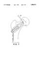
- FIGS. 3-12illustrate the different stages of an operation for implanting the prosthesis.
- FIGS. 1 and 2which illustrate the prosthetic hip joint in an implanted state
- 1designates the primary fixture
- 2designates the secondary fixture.
- the primary fixtureis in the form of a cylindrical main bolt 3 having a head 4, which preferably has a square shape, and a tubular end part 5 with a longitudinal bore.
- the tubular part 5comprises an inner bore part 6 and and an outer bore part 7.
- the inner part 6is provided with internal threads 8.
- the outer part 7is provided with at least two longitudinal slits 9,9'.
- the inside 10 of the outer part 7flares conically outwards.
- the internal threads 8 and the conically flaring part 10are complementary to an attachment screw or bolt 11 having an externally threaded end part 12, a head 13 and a shaft 14 tapering conically from the head 13 towards the threaded part 12.
- the attachment bolt 11is in engagement with the internal threads of the main bolt 3.
- the main bolt 3is provided with relatively large and widely spaced threads 15 on a part of its outside, the remainder 16 of its outside, substantially corresponding to the outer part 7, being smooth. This smooth part is covered by a plastic layer or by another equivalent coating.
- the bolt 3is inserted in a channel 17 bored longitudinally and centrally through the collum 18 from the outside of the femur towards the head of the collum.
- the head 4 of the main bolt 3is located on the outside of the femur and is locked against rotation by means of an elongate plate 18 having a hole 19 with a shape complementary to the shape of the head 4 of the main bolt 3.
- the elongate plateis attached to the femoral shaft by means of screws 33.
- the secondary fixture 2is in the shape of a cylindrical plug 20.
- One part 21 of the plug 20is inserted into a recess 22 cut in the collum, cylindrically and co-axially with the channel 17.
- the outside of this part 21 of the plugpreferably is provided with threads 24 similar to the threads 15 on the main bolt 3, except on the part which is located innermost in the recess.
- the plug 20also is provided with a circumferential flange 25 limiting the insertion of the plug 20 into the cavity 22.
- the plug 20further is provided with a central through-hole 26 having two parts, an inner part 27 having an inner diameter corresponding to the outer diameter of the smooth part 16 of the bolt 3 and an outer part 28 permitting the insertion of a screw-driver or a similar tool for engaging the head of the attachment screw.
- the outer end of the through-holeis provided with a hexagonal shape 29 for engagement with a suitable hex-tool.
- the plugfinally is provided with a conical projection or attachment cone 30 for carrying the ball or caput 31 which is provided with a complementary conical hole 32.
- the primary and the secondary fixturesare preferably made of c.p. (commercially pure) titanium and may be subjected to a suitable surface treatment.
- the elongate plate 18preferably is made of a suitable titanium alloy, whereas its attachment screws 33 preferably should be made of c.p. titanium and for instance have a diameter of 4.5 mm.
- the attachment conecan be made of a titanium alloy or of c.p. titanium and should be treated in a suitable way to minimize the risk for fretting corrosion.
- the caputpreferably should be made of a ceramic material, also in order to minimize the risk for fretting corrosion.
- the socket or acetabulumis not part of the present invention and may be of any commerciably available kind which is suitable.
- the operation for implanting the hip joint prosthesisis preferably performed in two different stages (but may of course also be performed as a one-stage operation).
- the preoperative stage of the two-stage operationis illustrated in FIGS. 3 and 4, the first stage of the operation is illustrated in FIGS. 5 and 6 and the final, second stage of the operation is illustrated in FIGS. 7 to 12.
- FIG. 3shows an X-ray apparatus used in the pre-operative stage and its orientation relative to the patient. Two pictures are taken in orthogonal directions. A suitable length for the primary fixture and a suitable orientation thereof relative to the femoral shaft and the collum femoris is measured on the X-ray pictures, as illustrated in FIG. 4. Any differences in the length of the legs are measured. An estimate of the narrowest diameter of the collum is made in order to obtain an idea of the size of the implant to be used.
- the patientlies on a traction table with a bi-planar X-ray apparatus.
- the picturesare displayed on a video monitor.
- the femuris rotated inwardly about 20 degrees in order to cancel the angle of anteroversion.
- the position of the primary fixtureis marked on both the video displays in accordance with the results obtained from the pre-operative stage.
- By means of a lateral incision in the skinthe outer side of the femur is uncovered.
- the X-ray displaythe exact point of entrance for the primary fixture is determined.
- a "Kirchner"-wire or guiding pin provided with threadsis bored longitudinally through the collum from the outside of the femur under continuous X-ray control on the video display in order to obtain a central guide pin.
- the guide pinis bored through the caput and into the acetabulum in order to obtain a temporary fixation of the femur during the remainder of the first stage of the operation.
- a drill guideis then aligned with the guide pin and is locked by means of an external fixture.
- a channel 17is drilled along the guide pin to the depth determined in the pre-operative stage by means of a cannulated drill bit, this part of the operation being carefully cooled and being controlled on the X-ray display, cf FIG. 5.
- the primary fixture 3is screwed into the channel 17 and the guide pin is removed.
- the head 4 of the primary fixture 3is locked laterally against rotation by means of the elongate plate 18 which in turn is fixed against the femoral shaft by means of the two screws 33, cf FIG. 6.
- the primary fixturemay of course also be self-tapping.
- the primary fixture 3is left to heal into the bone tissue or osseointegrate in the collum during 3-6 months. It should be noted that, as mentioned above, the inner end of the primary fixture is covered by a plastic sleeve in order to prevent bone ingrowth.
- both the caput and the acetabulumessentially remain intact and serviceable to the extent existing before the operation during the entire healing time, which is an important advantage of the two-stage operation.
- a guide fixture for a cutting tool 34is attached, for instance to the implanted primary fixture 3, and aligned with the inner end of the primary fixture 3. The caput is then cut close the the inner end of the primary fixture and removed (FIG. 7).
- a cylindrical recess or hole 22is then cut longitudinally in the collum from the direction of the caput by means of a rotary cutting (milling) tool 35 having a longitudinal interior bore 36 which extends from the cutting surface and which has an inner diameter slightly larger than the diameter of the inner end of the primary fixture 3.
- the edge of the bore 36should be provided with an interior circumferential rounded bead 37 and the smallest inner diameter of the bore at the bead should be close to the diameter of the inner end of the primary fixture. In this way the primary fixture can be, and is to be, used as a guide for the cutting tool.
- the circumferential beadis important since it allows smaller misalignments of the cutting tool.
- Threadsare cut into the bone tissue on the inside of the recess 22 in the collum.
- the attachment bolt 11is inserted into the tubular end of the primary fixture and a secondary fixture having a fitting size is screwed into the recess 22 in the collum, using the primary fixture 3 as a guide, until the flange 25 abuts the cortical bone on the cut end surface of the collum.
- the unthreaded part on the tip of the secondary fixturewill aid in guiding the secondary fixture into the recess 22, cf FIG. 10.
- the secondary fixturemay of course also be self-tapping.
- a screw-driver 38is then inserted into the central through-hole 28 in the secondary fixture and the bolt 11 is tightened, resulting in that the walls of the hollow, conically flaring part of the primary fixture are expanded against the inside of the secondary fixture. This will give a strong and stiff attachment of the secondary fixture to the primary fixture.
- a ball or caput 31is mounted on the attachment cone 30 and a reduction or repositioning of the joint is made in order to test the stability of the joint and the length of the leg.
- the length of the legis corrected by using caputs having differently sized conical holes 32.
Landscapes
- Health & Medical Sciences (AREA)
- Life Sciences & Earth Sciences (AREA)
- Orthopedic Medicine & Surgery (AREA)
- Surgery (AREA)
- Public Health (AREA)
- General Health & Medical Sciences (AREA)
- Animal Behavior & Ethology (AREA)
- Veterinary Medicine (AREA)
- Engineering & Computer Science (AREA)
- Biomedical Technology (AREA)
- Heart & Thoracic Surgery (AREA)
- Oral & Maxillofacial Surgery (AREA)
- Nuclear Medicine, Radiotherapy & Molecular Imaging (AREA)
- Medical Informatics (AREA)
- Molecular Biology (AREA)
- Dentistry (AREA)
- Cardiology (AREA)
- Transplantation (AREA)
- Vascular Medicine (AREA)
- Radiology & Medical Imaging (AREA)
- Pathology (AREA)
- Neurology (AREA)
- Prostheses (AREA)
- Materials For Medical Uses (AREA)
- Surgical Instruments (AREA)
Abstract
Description
Claims (12)
Applications Claiming Priority (3)
| Application Number | Priority Date | Filing Date | Title |
|---|---|---|---|
| SE9102216ASE9102216D0 (en) | 1991-07-23 | 1991-07-23 | HIP JOINT PROSTHESIS |
| SE9102216 | 1991-07-23 | ||
| PCT/SE1992/000511WO1993001769A1 (en) | 1991-07-23 | 1992-07-07 | Hip joint prosthesis |
Publications (1)
| Publication Number | Publication Date |
|---|---|
| US5800553Atrue US5800553A (en) | 1998-09-01 |
Family
ID=20383362
Family Applications (1)
| Application Number | Title | Priority Date | Filing Date |
|---|---|---|---|
| US08/185,814Expired - Fee RelatedUS5800553A (en) | 1991-07-23 | 1992-07-04 | Hip joint prosthesis to be permanently anchored within a femur of a patient |
Country Status (10)
| Country | Link |
|---|---|
| US (1) | US5800553A (en) |
| EP (1) | EP0600917B1 (en) |
| AT (1) | ATE184469T1 (en) |
| AU (1) | AU2333092A (en) |
| DE (1) | DE69230001T2 (en) |
| DK (1) | DK0600917T3 (en) |
| ES (1) | ES2139603T3 (en) |
| GR (1) | GR3032100T3 (en) |
| SE (1) | SE9102216D0 (en) |
| WO (1) | WO1993001769A1 (en) |
Cited By (62)
| Publication number | Priority date | Publication date | Assignee | Title |
|---|---|---|---|---|
| US6197065B1 (en) | 1993-11-01 | 2001-03-06 | Biomet, Inc. | Method and apparatus for segmental bone replacement |
| US20030171819A1 (en)* | 2002-03-11 | 2003-09-11 | Sotereanos Nicholas G. | Modular hip implants |
| US20030187514A1 (en)* | 2002-03-26 | 2003-10-02 | Mcminn Derek James Wallace | Hip joint prosthesis |
| WO2003086242A1 (en)* | 2002-04-11 | 2003-10-23 | Theodore Crofford | Femoral neck fixation prosthesis |
| US6656184B1 (en) | 2002-01-09 | 2003-12-02 | Biomet, Inc. | Bone screw with helical spring |
| US20040015172A1 (en)* | 2000-11-10 | 2004-01-22 | Lutz Biedermann | Bone screw |
| US20050015153A1 (en)* | 2002-05-24 | 2005-01-20 | Medicine Lodge, Inc. | Implants and related methods and apparatus for securing an implant on an articulating surface of an orthopedic joint |
| US20060004461A1 (en)* | 2003-12-30 | 2006-01-05 | Medicinelodge, Inc. | Methods for mounting a tibial condylar implant |
| US20060009855A1 (en)* | 2004-07-09 | 2006-01-12 | Medicinelodge, Inc. | Trochlear groove implants and related methods and instruments |
| US20060009853A1 (en)* | 2003-12-30 | 2006-01-12 | Medicinelodge, Inc. | Tethered joint bearing implants and systems |
| US20060116775A1 (en)* | 1993-11-01 | 2006-06-01 | Biomet Manufacturing Corp. | Compliant fixation for pelvis |
| US20060129247A1 (en)* | 1993-11-01 | 2006-06-15 | Bioment Manufacturing Corp. | Intramedullary compliant fixation |
| US20060161261A1 (en)* | 2004-05-04 | 2006-07-20 | Biomet Manufacturing Corp. | Method and apparatus for constructing a modular acetabulum |
| US20060217720A1 (en)* | 2003-03-13 | 2006-09-28 | Poonung Chieng | Artificial hip joint without a shaft |
| US7141073B2 (en) | 1993-11-01 | 2006-11-28 | Biomet, Inc. | Compliant fixation of external prosthesis |
| EP1726273A1 (en)* | 2005-05-24 | 2006-11-29 | Zimmer GmbH | Hip joint prosthesis |
| US7229445B2 (en) | 2004-06-21 | 2007-06-12 | Synthes (Usa) | Bone plate with bladed portion |
| US7255712B1 (en) | 1997-04-15 | 2007-08-14 | Active Implants Corporation | Bone growth promoting implant |
| US20070255420A1 (en)* | 2005-08-26 | 2007-11-01 | Johnson James F | Thrust plate hip prosthesis |
| US7374576B1 (en) | 2004-01-22 | 2008-05-20 | Medicinelodge, Inc | Polyaxial orthopedic fastening apparatus with independent locking modes |
| US7572295B2 (en) | 2001-12-04 | 2009-08-11 | Active Implants Corporation | Cushion bearing implants for load bearing applications |
| US7641698B1 (en)* | 2004-06-04 | 2010-01-05 | Biomet Manufacturing Corp. | Modular hip joint implant |
| US20100023131A1 (en)* | 2008-07-24 | 2010-01-28 | Howmedica Osteonics Corp. | Femoral head prosthesis |
| US7670383B1 (en) | 2004-05-04 | 2010-03-02 | Biomet Manufacturing Corp. | Pubic catch |
| US7758653B2 (en) | 2002-05-23 | 2010-07-20 | Active Implants Corporation | Implants |
| WO2011005195A1 (en)* | 2009-07-10 | 2011-01-13 | Milux Holding S.A. | Hip joint device, system and method |
| US7951176B2 (en) | 2003-05-30 | 2011-05-31 | Synthes Usa, Llc | Bone plate |
| US20110178604A1 (en)* | 2010-01-18 | 2011-07-21 | Biomet Manufacturing Corp. | Expandable Endoprosthesis |
| US20110196502A1 (en)* | 2010-02-05 | 2011-08-11 | Walls James A | Methods of Using Water-Soluble Inorganic Compounds for Implants |
| US8029573B2 (en) | 2006-12-07 | 2011-10-04 | Ihip Surgical, Llc | Method and apparatus for total hip replacement |
| US8382762B2 (en)* | 2001-09-19 | 2013-02-26 | James K Brannon | Endoscopic bone debridement |
| US20130204390A1 (en)* | 2006-12-07 | 2013-08-08 | Ihip Surgical, Llc | Method and apparatus for attachment in a modular hip replacement or fracture fixation device |
| US8579985B2 (en) | 2006-12-07 | 2013-11-12 | Ihip Surgical, Llc | Method and apparatus for hip replacement |
| CN103445886A (en)* | 2013-03-07 | 2013-12-18 | 刘礼初 | Biotype artificial hip joint surface replacement prostheses |
| US20140094855A1 (en)* | 2012-09-28 | 2014-04-03 | Jason M. Chavarria | Adjustable height arthroplasty plate |
| JP2014511213A (en)* | 2011-02-04 | 2014-05-15 | デピュイ・(アイルランド) | Arthroplasty plate |
| US20140277530A1 (en)* | 2013-03-15 | 2014-09-18 | Smed-Ta/Td, Llc | Fixation of bone implants |
| US8915970B2 (en) | 2013-02-08 | 2014-12-23 | Biomet Manufacturing, Llc | Transdermal prosthesis |
| US8968415B2 (en) | 2012-02-07 | 2015-03-03 | Biomet Manufacturing, Llc | Implant fixation device |
| US20150073489A1 (en)* | 2013-09-06 | 2015-03-12 | Biomet Manufacturing, Llc | Implant fixation assembly |
| US20150094727A1 (en)* | 2012-07-26 | 2015-04-02 | Patrick M. Birmingham | Method and device for joint replacement |
| US20150182340A1 (en)* | 2012-08-06 | 2015-07-02 | Universite de Bordeaux | Condylar prosthesis for a temporo-mandibular joint |
| US9504578B2 (en) | 2011-04-06 | 2016-11-29 | Depuy Synthes Products, Inc | Revision hip prosthesis having an implantable distal stem component |
| US9561109B2 (en) | 2013-03-13 | 2017-02-07 | Depuy Synthes Products, Inc | Orthopaedic implant and method of installing same |
| US9622870B2 (en) | 2011-03-29 | 2017-04-18 | Depuy (Ireland) | Implant |
| US9717545B2 (en) | 2007-10-30 | 2017-08-01 | DePuy Synthes Products, Inc. | Taper disengagement tool |
| US9867720B2 (en) | 2010-09-01 | 2018-01-16 | DePuy Synthes Products, Inc. | Disassembly tool |
| US10166118B2 (en) | 2010-06-15 | 2019-01-01 | DePuy Synthes Products, Inc. | Spiral assembly tool |
| US10335211B2 (en) | 2004-01-26 | 2019-07-02 | DePuy Synthes Products, Inc. | Highly-versatile variable-angle bone plate system |
| US10342586B2 (en) | 2003-08-26 | 2019-07-09 | DePuy Synthes Products, Inc. | Bone plate |
| US10624686B2 (en) | 2016-09-08 | 2020-04-21 | DePuy Synthes Products, Inc. | Variable angel bone plate |
| US20200129297A1 (en)* | 2018-10-25 | 2020-04-30 | Revision Technologies Llc | Interconnected implants and methods |
| US10772665B2 (en) | 2018-03-29 | 2020-09-15 | DePuy Synthes Products, Inc. | Locking structures for affixing bone anchors to a bone plate, and related systems and methods |
| US10820930B2 (en) | 2016-09-08 | 2020-11-03 | DePuy Synthes Products, Inc. | Variable angle bone plate |
| US20200390559A1 (en)* | 2019-06-12 | 2020-12-17 | United States Government As Represented By The Department Of Veterans Affairs | Femoral head arthroplasty system |
| US10905476B2 (en) | 2016-09-08 | 2021-02-02 | DePuy Synthes Products, Inc. | Variable angle bone plate |
| US10925651B2 (en) | 2018-12-21 | 2021-02-23 | DePuy Synthes Products, Inc. | Implant having locking holes with collection cavity for shavings |
| US11013541B2 (en) | 2018-04-30 | 2021-05-25 | DePuy Synthes Products, Inc. | Threaded locking structures for affixing bone anchors to a bone plate, and related systems and methods |
| US11026727B2 (en) | 2018-03-20 | 2021-06-08 | DePuy Synthes Products, Inc. | Bone plate with form-fitting variable-angle locking hole |
| US11259851B2 (en) | 2003-08-26 | 2022-03-01 | DePuy Synthes Products, Inc. | Bone plate |
| US11291484B2 (en) | 2004-01-26 | 2022-04-05 | DePuy Synthes Products, Inc. | Highly-versatile variable-angle bone plate system |
| TWI886919B (en)* | 2024-04-23 | 2025-06-11 | 國立勤益科技大學 | Covered artificial hip assistive device |
Families Citing this family (16)
| Publication number | Priority date | Publication date | Assignee | Title |
|---|---|---|---|---|
| SE9200597D0 (en)* | 1992-02-28 | 1992-02-28 | Astra Ab | HIP JOINT PROSTHESIS II |
| CH685533A5 (en)* | 1992-10-13 | 1995-08-15 | Philipp Rolf Kropf Albert Geis | Modular hip prosthesis stem. |
| SE9501829D0 (en)* | 1995-05-17 | 1995-05-17 | Astra Ab | Drill guide |
| SE9501828D0 (en)* | 1995-05-17 | 1995-05-17 | Astra Ab | Cutting guide |
| DE19601340C1 (en)* | 1996-01-16 | 1997-06-05 | Eska Implants Gmbh & Co | Endoprosthesis for neck of femur for artificial hip joint |
| ES2204234B2 (en)* | 2001-05-16 | 2005-04-16 | Jose Martinez Tetas | PROTECTIVE ADAPTATION DEVICE FOR HIP AND SHOULDER. |
| US7297166B2 (en) | 2003-06-25 | 2007-11-20 | Depuy Products, Inc. | Assembly tool for modular implants and associated method |
| US7074224B2 (en) | 2003-06-25 | 2006-07-11 | Depuy Products, Inc. | Modular tapered reamer for bone preparation and associated method |
| US8998919B2 (en) | 2003-06-25 | 2015-04-07 | DePuy Synthes Products, LLC | Assembly tool for modular implants, kit and associated method |
| US7582092B2 (en) | 2003-06-25 | 2009-09-01 | Depuy Products, Inc. | Assembly tool for modular implants and associated method |
| US7338496B1 (en) | 2003-08-29 | 2008-03-04 | Biomet Manufacturing Corp. | Method and apparatus for positioning an implant |
| US7785328B2 (en) | 2003-12-30 | 2010-08-31 | Depuy Products, Inc. | Minimally invasive bone miller apparatus |
| US8597298B2 (en)* | 2006-09-29 | 2013-12-03 | DePuy Synthes Products, LLC | Proximal reamer |
| GB0720596D0 (en)* | 2007-10-22 | 2007-11-28 | Smith & Nephew | Joint prosthesis |
| US8518050B2 (en) | 2007-10-31 | 2013-08-27 | DePuy Synthes Products, LLC | Modular taper assembly device |
| US8167882B2 (en) | 2008-09-30 | 2012-05-01 | Depuy Products, Inc. | Minimally invasive bone miller apparatus |
Citations (27)
| Publication number | Priority date | Publication date | Assignee | Title |
|---|---|---|---|---|
| US2381050A (en)* | 1943-12-04 | 1945-08-07 | Mervyn G Hardinge | Fracture reducing device |
| US2397545A (en)* | 1945-02-13 | 1946-04-02 | Mervyn G Hardinge | Self-adjusting fracture reducing device |
| US2612159A (en)* | 1949-03-01 | 1952-09-30 | Marie B Collison | Trochanteric plate for bone surgery |
| US3102536A (en)* | 1960-12-07 | 1963-09-03 | Robert M Rose | Hip prosthesis |
| US3806957A (en)* | 1972-05-04 | 1974-04-30 | Y Shersher | Endoprosthesis of the proximal portion of the femur |
| US3987499A (en)* | 1973-08-10 | 1976-10-26 | Sybron Corporation | Surgical implant and method for its production |
| DE2724234A1 (en)* | 1976-06-03 | 1977-12-22 | Arnold Prof Dr Med Huggler | ARTICULATED PROSTHESIS PART WITH BALL HEAD |
| SU602171A1 (en)* | 1975-11-26 | 1978-04-15 | Yaselskij Yurij M | Apparatus for osteosynthesis of neck of femur |
| DE2646478A1 (en)* | 1976-10-14 | 1978-04-20 | Rosenthal Technik Ag | JOINT ENDOPROTHESIS |
| US4187559A (en)* | 1975-04-04 | 1980-02-12 | Sybron Corporation | Body joint endoprosthesis |
| FR2438470A1 (en)* | 1978-10-12 | 1980-05-09 | Rambert Andre | HIP PROSTHESIS |
| DE2854334A1 (en)* | 1978-12-15 | 1980-06-19 | Fritz Dr Erler | Anchoring members for artificial hip joint - has main shaft with enlarged top with hole tapped at angle for sloping pin |
| US4388921A (en)* | 1980-05-28 | 1983-06-21 | Institut Straumann Ag | Device comprising a plate and screws for fastening a plate to a bone |
| US4409974A (en)* | 1981-06-29 | 1983-10-18 | Freedland Jeffrey A | Bone-fixating surgical implant device |
| GB2166359A (en)* | 1984-11-06 | 1986-05-08 | Bristol Myers Co | Compression hip screw assembly |
| WO1986003962A1 (en)* | 1985-01-11 | 1986-07-17 | S.A. Manufacture Belge De Gembloux | Joint member for a hip prosthesis |
| FR2578739A1 (en)* | 1985-03-12 | 1986-09-19 | Rambert Andre | Humeral prosthesis |
| US4621629A (en)* | 1985-08-12 | 1986-11-11 | Harrington Arthritis Research Center | Compression hip screw |
| DE3607824A1 (en)* | 1986-01-21 | 1987-09-10 | Werner Dr Med Steinleitner | Cementless, rotationally stable compression hip endoprosthesis |
| US4795473A (en)* | 1987-01-09 | 1989-01-03 | Grimes James B | Extramedullary femoral head-neck prosthesis and method of implanting same |
| US4878916A (en)* | 1986-03-13 | 1989-11-07 | Jean-Luc Rhenter | Prosthetic cupule |
| WO1989011837A1 (en)* | 1988-06-10 | 1989-12-14 | Albrektsson Bjoern | Hip joint prosthesis |
| DE3917285A1 (en)* | 1989-05-27 | 1990-11-29 | Wolfgang Roth | Shoulder prosthesis - has condyle and acetabulum made of specified material |
| DE3921030A1 (en)* | 1989-06-27 | 1991-01-03 | Klaus Kleinhoff | Hip joint endoprosthesis - has shaft with annular groove which grips pieces of fractured femur |
| US5074879A (en)* | 1990-10-26 | 1991-12-24 | Pappas Michael J | Prosthetic device with modular stem |
| US5087260A (en)* | 1989-09-15 | 1992-02-11 | Fixel Irving E | Total femoral hip system |
| EP0515003A1 (en)* | 1989-04-25 | 1992-11-25 | Per-Ingvar Branemark | Anchor element for holding a joint component of a hip joint |
- 1991
- 1991-07-23SESE9102216Apatent/SE9102216D0/enunknown
- 1992
- 1992-07-04USUS08/185,814patent/US5800553A/ennot_activeExpired - Fee Related
- 1992-07-07DKDK92915806Tpatent/DK0600917T3/enactive
- 1992-07-07AUAU23330/92Apatent/AU2333092A/ennot_activeAbandoned
- 1992-07-07ATAT92915806Tpatent/ATE184469T1/ennot_activeIP Right Cessation
- 1992-07-07DEDE69230001Tpatent/DE69230001T2/ennot_activeExpired - Fee Related
- 1992-07-07EPEP92915806Apatent/EP0600917B1/ennot_activeExpired - Lifetime
- 1992-07-07ESES92915806Tpatent/ES2139603T3/ennot_activeExpired - Lifetime
- 1992-07-07WOPCT/SE1992/000511patent/WO1993001769A1/enactiveIP Right Grant
- 1999
- 1999-12-10GRGR990403190Tpatent/GR3032100T3/enunknown
Patent Citations (30)
| Publication number | Priority date | Publication date | Assignee | Title |
|---|---|---|---|---|
| US2381050A (en)* | 1943-12-04 | 1945-08-07 | Mervyn G Hardinge | Fracture reducing device |
| US2397545A (en)* | 1945-02-13 | 1946-04-02 | Mervyn G Hardinge | Self-adjusting fracture reducing device |
| US2612159A (en)* | 1949-03-01 | 1952-09-30 | Marie B Collison | Trochanteric plate for bone surgery |
| US3102536A (en)* | 1960-12-07 | 1963-09-03 | Robert M Rose | Hip prosthesis |
| US3806957A (en)* | 1972-05-04 | 1974-04-30 | Y Shersher | Endoprosthesis of the proximal portion of the femur |
| US3987499A (en)* | 1973-08-10 | 1976-10-26 | Sybron Corporation | Surgical implant and method for its production |
| US4187559A (en)* | 1975-04-04 | 1980-02-12 | Sybron Corporation | Body joint endoprosthesis |
| SU602171A1 (en)* | 1975-11-26 | 1978-04-15 | Yaselskij Yurij M | Apparatus for osteosynthesis of neck of femur |
| DE2724234A1 (en)* | 1976-06-03 | 1977-12-22 | Arnold Prof Dr Med Huggler | ARTICULATED PROSTHESIS PART WITH BALL HEAD |
| US4129903A (en)* | 1976-06-03 | 1978-12-19 | Huggler Arnold H | Hinge prosthetic joint with ball head |
| DE2646478A1 (en)* | 1976-10-14 | 1978-04-20 | Rosenthal Technik Ag | JOINT ENDOPROTHESIS |
| US4268919A (en)* | 1976-10-14 | 1981-05-26 | Rosenthal Technik Ag | Joint endoprosthesis |
| FR2438470A1 (en)* | 1978-10-12 | 1980-05-09 | Rambert Andre | HIP PROSTHESIS |
| DE2854334A1 (en)* | 1978-12-15 | 1980-06-19 | Fritz Dr Erler | Anchoring members for artificial hip joint - has main shaft with enlarged top with hole tapped at angle for sloping pin |
| US4388921A (en)* | 1980-05-28 | 1983-06-21 | Institut Straumann Ag | Device comprising a plate and screws for fastening a plate to a bone |
| US4409974A (en)* | 1981-06-29 | 1983-10-18 | Freedland Jeffrey A | Bone-fixating surgical implant device |
| GB2166359A (en)* | 1984-11-06 | 1986-05-08 | Bristol Myers Co | Compression hip screw assembly |
| US5007935A (en)* | 1985-01-11 | 1991-04-16 | S. A. Manufacture Belge De Gembloux | Joint member for a hip prosthesis |
| WO1986003962A1 (en)* | 1985-01-11 | 1986-07-17 | S.A. Manufacture Belge De Gembloux | Joint member for a hip prosthesis |
| FR2578739A1 (en)* | 1985-03-12 | 1986-09-19 | Rambert Andre | Humeral prosthesis |
| US4621629A (en)* | 1985-08-12 | 1986-11-11 | Harrington Arthritis Research Center | Compression hip screw |
| DE3607824A1 (en)* | 1986-01-21 | 1987-09-10 | Werner Dr Med Steinleitner | Cementless, rotationally stable compression hip endoprosthesis |
| US4878916A (en)* | 1986-03-13 | 1989-11-07 | Jean-Luc Rhenter | Prosthetic cupule |
| US4795473A (en)* | 1987-01-09 | 1989-01-03 | Grimes James B | Extramedullary femoral head-neck prosthesis and method of implanting same |
| WO1989011837A1 (en)* | 1988-06-10 | 1989-12-14 | Albrektsson Bjoern | Hip joint prosthesis |
| EP0515003A1 (en)* | 1989-04-25 | 1992-11-25 | Per-Ingvar Branemark | Anchor element for holding a joint component of a hip joint |
| DE3917285A1 (en)* | 1989-05-27 | 1990-11-29 | Wolfgang Roth | Shoulder prosthesis - has condyle and acetabulum made of specified material |
| DE3921030A1 (en)* | 1989-06-27 | 1991-01-03 | Klaus Kleinhoff | Hip joint endoprosthesis - has shaft with annular groove which grips pieces of fractured femur |
| US5087260A (en)* | 1989-09-15 | 1992-02-11 | Fixel Irving E | Total femoral hip system |
| US5074879A (en)* | 1990-10-26 | 1991-12-24 | Pappas Michael J | Prosthetic device with modular stem |
Cited By (149)
| Publication number | Priority date | Publication date | Assignee | Title |
|---|---|---|---|---|
| US20060116775A1 (en)* | 1993-11-01 | 2006-06-01 | Biomet Manufacturing Corp. | Compliant fixation for pelvis |
| US7476254B2 (en) | 1993-11-01 | 2009-01-13 | Biomet Manufacturing Corporation | Compliant fixation for pelvis |
| US7141073B2 (en) | 1993-11-01 | 2006-11-28 | Biomet, Inc. | Compliant fixation of external prosthesis |
| US20060129247A1 (en)* | 1993-11-01 | 2006-06-15 | Bioment Manufacturing Corp. | Intramedullary compliant fixation |
| US6197065B1 (en) | 1993-11-01 | 2001-03-06 | Biomet, Inc. | Method and apparatus for segmental bone replacement |
| US6508841B2 (en) | 1993-11-01 | 2003-01-21 | Biomet, Inc. | Method and apparatus for segmental bone replacement |
| US7722678B2 (en) | 1993-11-01 | 2010-05-25 | Biomet Manufacturing Corp. | Intramedullary compliant fixation |
| US6712855B2 (en) | 1993-11-01 | 2004-03-30 | Biomet, Inc. | Compliant tibial tray assembly |
| US7255712B1 (en) | 1997-04-15 | 2007-08-14 | Active Implants Corporation | Bone growth promoting implant |
| US9468483B2 (en) | 2000-11-10 | 2016-10-18 | Biedermann Technologies Gmbh & Co. Kg | Bone screw |
| US20040015172A1 (en)* | 2000-11-10 | 2004-01-22 | Lutz Biedermann | Bone screw |
| US8968372B2 (en) | 2000-11-10 | 2015-03-03 | Biedermann Technologies Gmbh & Co. Kg | Bone screw |
| US8137389B2 (en)* | 2000-11-10 | 2012-03-20 | Biedermann Motech Gmbh & Co. Kg | Bone screw |
| US8382762B2 (en)* | 2001-09-19 | 2013-02-26 | James K Brannon | Endoscopic bone debridement |
| US7572295B2 (en) | 2001-12-04 | 2009-08-11 | Active Implants Corporation | Cushion bearing implants for load bearing applications |
| US8814946B2 (en) | 2001-12-04 | 2014-08-26 | Active Implants Corporation | Cushion bearing implants for load bearing applications |
| EP2145604A1 (en) | 2001-12-04 | 2010-01-20 | Active Implants Corporation | Cushion bearing implants for load bearing applications |
| US6656184B1 (en) | 2002-01-09 | 2003-12-02 | Biomet, Inc. | Bone screw with helical spring |
| US20030171819A1 (en)* | 2002-03-11 | 2003-09-11 | Sotereanos Nicholas G. | Modular hip implants |
| US7247171B2 (en) | 2002-03-11 | 2007-07-24 | Sotereanos Nicholas G | Modular hip implants |
| US20030187514A1 (en)* | 2002-03-26 | 2003-10-02 | Mcminn Derek James Wallace | Hip joint prosthesis |
| US8177852B2 (en) | 2002-03-26 | 2012-05-15 | Smith & Nephew, Inc. | Hip joint prosthesis |
| US8808391B2 (en) | 2002-03-26 | 2014-08-19 | T.J. Smith & Nephew, Limited | Hip joint prosthesis |
| US7879106B2 (en)* | 2002-03-26 | 2011-02-01 | Smith & Nephew, Inc. | Hip joint prosthesis |
| US20050010230A1 (en)* | 2002-04-11 | 2005-01-13 | Crofford Theodore W. | Method of implanting a femoral neck fixation prosthesis |
| US20080208200A1 (en)* | 2002-04-11 | 2008-08-28 | Howmedica Osteonics Corp. | Drilling guide for use in implanting a femoral neck fixation prosthesis |
| US20070162035A1 (en)* | 2002-04-11 | 2007-07-12 | Crofford Theodore W | Method of preparing an acetabulum for receiving a head of a femoral prosthesis |
| US20040162621A1 (en)* | 2002-04-11 | 2004-08-19 | Crofford Theodore W. | Femoral neck fixation prosthesis |
| US7104995B2 (en)* | 2002-04-11 | 2006-09-12 | Crofford Theodore W | Method of preparing an acetabulum for receiving a head of a femoral prosthesis |
| WO2003086242A1 (en)* | 2002-04-11 | 2003-10-23 | Theodore Crofford | Femoral neck fixation prosthesis |
| US20100114101A1 (en)* | 2002-04-11 | 2010-05-06 | Howmedica Osteonics Corp. | Method of resecting a femoral head for implantation of a femoral neck fixation prosthesis |
| US6695883B2 (en)* | 2002-04-11 | 2004-02-24 | Theodore W. Crofford | Femoral neck fixation prosthesis |
| AU2003224886B2 (en)* | 2002-04-11 | 2008-10-23 | Howmedica Osteonics Corp. | Femoral neck fixation prosthesis |
| US20050049714A1 (en)* | 2002-04-11 | 2005-03-03 | Crofford Theodore W. | Method of resecting a femoral head for implantation of a femoral neck fixation prosthesis |
| US20050010232A1 (en)* | 2002-04-11 | 2005-01-13 | Crofford Theodre W. | Method of implanting a femoral neck fixation prosthesis |
| US7695474B2 (en) | 2002-04-11 | 2010-04-13 | Howmedica Osteonics Corp. | Method of preparing an acetabulum for receiving a head of a femoral prosthesis |
| US7758653B2 (en) | 2002-05-23 | 2010-07-20 | Active Implants Corporation | Implants |
| US20050015153A1 (en)* | 2002-05-24 | 2005-01-20 | Medicine Lodge, Inc. | Implants and related methods and apparatus for securing an implant on an articulating surface of an orthopedic joint |
| US7922772B2 (en) | 2002-05-24 | 2011-04-12 | Zimmer, Inc. | Implants and related methods and apparatus for securing an implant on an articulating surface of an orthopedic joint |
| US20060217720A1 (en)* | 2003-03-13 | 2006-09-28 | Poonung Chieng | Artificial hip joint without a shaft |
| US9308034B2 (en) | 2003-05-30 | 2016-04-12 | DePuy Synthes Products, Inc. | Bone plate |
| US11419647B2 (en) | 2003-05-30 | 2022-08-23 | DePuy Synthes Products, Inc. | Bone plate |
| US7951176B2 (en) | 2003-05-30 | 2011-05-31 | Synthes Usa, Llc | Bone plate |
| US10653466B2 (en) | 2003-05-30 | 2020-05-19 | DePuy Synthes Products, Inc. | Bone plate |
| US9931148B2 (en) | 2003-05-30 | 2018-04-03 | DePuy Synthes Products, Inc. | Bone plate |
| US10231768B2 (en) | 2003-05-30 | 2019-03-19 | DePuy Synthes Products, Inc. | Methods for implanting bone plates |
| US11259851B2 (en) | 2003-08-26 | 2022-03-01 | DePuy Synthes Products, Inc. | Bone plate |
| US10342586B2 (en) | 2003-08-26 | 2019-07-09 | DePuy Synthes Products, Inc. | Bone plate |
| US7867280B2 (en) | 2003-12-30 | 2011-01-11 | Zimmer, Inc. | Methods for mounting and using tethered joint bearing implants |
| US20060004461A1 (en)* | 2003-12-30 | 2006-01-05 | Medicinelodge, Inc. | Methods for mounting a tibial condylar implant |
| US20060009853A1 (en)* | 2003-12-30 | 2006-01-12 | Medicinelodge, Inc. | Tethered joint bearing implants and systems |
| US20060009774A1 (en)* | 2003-12-30 | 2006-01-12 | Medicinelodge Inc. | Methods for mounting and using tethered joint bearing implants |
| US8236060B2 (en) | 2003-12-30 | 2012-08-07 | Zimmer, Inc. | Tethered joint bearing implants and systems |
| US7462199B2 (en)* | 2003-12-30 | 2008-12-09 | Medicinelodge, Inc. | Methods for mounting a tibial condylar implant |
| US8157871B2 (en) | 2004-01-22 | 2012-04-17 | Michael D Ries | Femoral HIP prosthesis and method of implantation |
| US7374576B1 (en) | 2004-01-22 | 2008-05-20 | Medicinelodge, Inc | Polyaxial orthopedic fastening apparatus with independent locking modes |
| US7534271B2 (en) | 2004-01-22 | 2009-05-19 | Smith + Nephew | Femoral hip prosthesis and method of implantation |
| US10335211B2 (en) | 2004-01-26 | 2019-07-02 | DePuy Synthes Products, Inc. | Highly-versatile variable-angle bone plate system |
| US11291484B2 (en) | 2004-01-26 | 2022-04-05 | DePuy Synthes Products, Inc. | Highly-versatile variable-angle bone plate system |
| US8048166B2 (en) | 2004-05-04 | 2011-11-01 | Biomet Manufacturing Corp. | Method and apparatus for constructing a modular acetabulum |
| US7670383B1 (en) | 2004-05-04 | 2010-03-02 | Biomet Manufacturing Corp. | Pubic catch |
| US20060161261A1 (en)* | 2004-05-04 | 2006-07-20 | Biomet Manufacturing Corp. | Method and apparatus for constructing a modular acetabulum |
| US8066779B2 (en) | 2004-06-04 | 2011-11-29 | Biomet Manufacturing Corp. | Modular hip joint implant |
| US20100114324A1 (en)* | 2004-06-04 | 2010-05-06 | Biomet Manufacturing Corp. | Modular Hip Joint Implant |
| US7641698B1 (en)* | 2004-06-04 | 2010-01-05 | Biomet Manufacturing Corp. | Modular hip joint implant |
| US7229445B2 (en) | 2004-06-21 | 2007-06-12 | Synthes (Usa) | Bone plate with bladed portion |
| US8157867B2 (en) | 2004-07-09 | 2012-04-17 | Zimmer, Inc. | Trochlear groove implants and related methods and instruments |
| US20060009855A1 (en)* | 2004-07-09 | 2006-01-12 | Medicinelodge, Inc. | Trochlear groove implants and related methods and instruments |
| US8852195B2 (en) | 2004-07-09 | 2014-10-07 | Zimmer, Inc. | Guide templates for surgical implants and related methods |
| US9763790B2 (en) | 2005-05-24 | 2017-09-19 | Zimmer Gmbh | Femoral neck prosthesis |
| US20090076619A1 (en)* | 2005-05-24 | 2009-03-19 | Zimmer Gmbh | Femoral neck prosthesis |
| EP1726273A1 (en)* | 2005-05-24 | 2006-11-29 | Zimmer GmbH | Hip joint prosthesis |
| US20070255420A1 (en)* | 2005-08-26 | 2007-11-01 | Johnson James F | Thrust plate hip prosthesis |
| US7569075B2 (en)* | 2005-08-26 | 2009-08-04 | Johnson James F | Thrust plate hip prosthesis |
| US8795381B2 (en)* | 2006-12-07 | 2014-08-05 | Ihip Surgical, Llc | Methods and systems for hip replacement |
| US8579985B2 (en) | 2006-12-07 | 2013-11-12 | Ihip Surgical, Llc | Method and apparatus for hip replacement |
| US8029573B2 (en) | 2006-12-07 | 2011-10-04 | Ihip Surgical, Llc | Method and apparatus for total hip replacement |
| US8211183B2 (en) | 2006-12-07 | 2012-07-03 | Ihip Surgical, Llc | Methods and systems for total hip replacement |
| US20140350690A1 (en)* | 2006-12-07 | 2014-11-27 | Ihip Surgical, Llc | Methods and systems for hip replacement |
| US20130204390A1 (en)* | 2006-12-07 | 2013-08-08 | Ihip Surgical, Llc | Method and apparatus for attachment in a modular hip replacement or fracture fixation device |
| US20120226361A1 (en)* | 2006-12-07 | 2012-09-06 | Ihip Surgical, Llc | Methods and systems for hip replacement |
| US9237949B2 (en) | 2006-12-07 | 2016-01-19 | Ihip Surgical, Llc | Method and apparatus for hip replacement |
| US8974540B2 (en)* | 2006-12-07 | 2015-03-10 | Ihip Surgical, Llc | Method and apparatus for attachment in a modular hip replacement or fracture fixation device |
| US9717545B2 (en) | 2007-10-30 | 2017-08-01 | DePuy Synthes Products, Inc. | Taper disengagement tool |
| US20100023131A1 (en)* | 2008-07-24 | 2010-01-28 | Howmedica Osteonics Corp. | Femoral head prosthesis |
| US8801799B2 (en) | 2008-07-24 | 2014-08-12 | Howmedica Osteonics Corp. | Femoral head prosthesis |
| US9351840B2 (en) | 2009-07-10 | 2016-05-31 | Peter Forsell | Hip joint device, system and method |
| WO2011005195A1 (en)* | 2009-07-10 | 2011-01-13 | Milux Holding S.A. | Hip joint device, system and method |
| US20110178604A1 (en)* | 2010-01-18 | 2011-07-21 | Biomet Manufacturing Corp. | Expandable Endoprosthesis |
| US8673018B2 (en)* | 2010-02-05 | 2014-03-18 | AMx Tek LLC | Methods of using water-soluble inorganic compounds for implants |
| US10117973B2 (en) | 2010-02-05 | 2018-11-06 | Orthomedex Llc | Methods of using water-soluble inorganic compounds for implants |
| US9592206B2 (en) | 2010-02-05 | 2017-03-14 | Orthomedex Llc | Methods of using water-soluble inorganic compounds for implants |
| US20110196502A1 (en)* | 2010-02-05 | 2011-08-11 | Walls James A | Methods of Using Water-Soluble Inorganic Compounds for Implants |
| US10166118B2 (en) | 2010-06-15 | 2019-01-01 | DePuy Synthes Products, Inc. | Spiral assembly tool |
| US10292837B2 (en) | 2010-09-01 | 2019-05-21 | Depuy Synthes Products Inc. | Disassembly tool |
| US9867720B2 (en) | 2010-09-01 | 2018-01-16 | DePuy Synthes Products, Inc. | Disassembly tool |
| US9877757B2 (en) | 2011-02-04 | 2018-01-30 | Depuy Ireland Unlimited Company | Arthroplasty plate |
| JP2014511213A (en)* | 2011-02-04 | 2014-05-15 | デピュイ・(アイルランド) | Arthroplasty plate |
| US11458022B2 (en) | 2011-03-29 | 2022-10-04 | Depuy Ireland Unlimited Company | Implant |
| US10010424B2 (en) | 2011-03-29 | 2018-07-03 | Depuy Ireland Unlimited Company | Implant |
| US9622870B2 (en) | 2011-03-29 | 2017-04-18 | Depuy (Ireland) | Implant |
| US9597188B2 (en) | 2011-04-06 | 2017-03-21 | DePuy Synthes Products, Inc. | Version-replicating instrument and orthopaedic surgical procedure for using the same to implant a revision hip prosthesis |
| US10064725B2 (en) | 2011-04-06 | 2018-09-04 | DePuy Synthes Products, Inc. | Distal reamer for use during an orthopaedic surgical procedure to implant a revision hip prosthesis |
| US9737405B2 (en) | 2011-04-06 | 2017-08-22 | DePuy Synthes Products, Inc. | Orthopaedic surgical procedure for implanting a revision hip prosthesis |
| US10772730B2 (en) | 2011-04-06 | 2020-09-15 | DePuy Synthes Products, Inc. | Finishing rasp and orthopaedic surgical procedure for using the same to implant a revision hip prosthesis |
| US10226345B2 (en) | 2011-04-06 | 2019-03-12 | DePuy Synthes Products, Inc. | Version-replicating instrument and orthopaedic surgical procedure for using the same to implant a revision hip prosthesis |
| US9504578B2 (en) | 2011-04-06 | 2016-11-29 | Depuy Synthes Products, Inc | Revision hip prosthesis having an implantable distal stem component |
| US10603173B2 (en) | 2011-04-06 | 2020-03-31 | DePuy Synthes Products, Inc. | Orthopaedic surgical procedure for implanting a revision hip prosthesis |
| US10888427B2 (en) | 2011-04-06 | 2021-01-12 | DePuy Synthes Products, Inc. | Distal reamer for use during an orthopaedic surgical procedure to implant a revision hip prosthesis |
| US9949833B2 (en) | 2011-04-06 | 2018-04-24 | DePuy Synthes Products, Inc. | Finishing RASP and orthopaedic surgical procedure for using the same to implant a revision hip prosthesis |
| US10925739B2 (en) | 2011-04-06 | 2021-02-23 | DePuy Synthes Products, Inc. | Version-replicating instrument and orthopaedic surgical procedure for using the same to implant a revision hip prosthesis |
| US8968415B2 (en) | 2012-02-07 | 2015-03-03 | Biomet Manufacturing, Llc | Implant fixation device |
| US10555743B2 (en) | 2012-07-26 | 2020-02-11 | Zimmer, Inc. | Method and device for joint replacement |
| US20150094727A1 (en)* | 2012-07-26 | 2015-04-02 | Patrick M. Birmingham | Method and device for joint replacement |
| US11730492B2 (en) | 2012-07-26 | 2023-08-22 | Zimmer, Inc. | Method and device for joint replacement |
| US9737315B2 (en)* | 2012-07-26 | 2017-08-22 | Zimmer, Inc. | Method and device for joint replacement |
| US20150182340A1 (en)* | 2012-08-06 | 2015-07-02 | Universite de Bordeaux | Condylar prosthesis for a temporo-mandibular joint |
| US9517135B2 (en)* | 2012-08-06 | 2016-12-13 | Universite de Bordeaux | Condylar prosthesis for a temporo-mandibular joint |
| US9398928B2 (en)* | 2012-09-28 | 2016-07-26 | DePuy Synthes Products, Inc. | Adjustable height arthroplasty plate |
| JP2014069076A (en)* | 2012-09-28 | 2014-04-21 | Depuy Synthes Products Llc | Height adjustable arthroplasty plate |
| US10342668B2 (en)* | 2012-09-28 | 2019-07-09 | DePuy Synthes Products, Inc. | Adjustable height arthroplasty plate |
| US20140094855A1 (en)* | 2012-09-28 | 2014-04-03 | Jason M. Chavarria | Adjustable height arthroplasty plate |
| US20180153702A1 (en)* | 2012-09-28 | 2018-06-07 | DePuy Synthes Products, Inc. | Adjustable height arthroplasty plate |
| US9883948B2 (en) | 2012-09-28 | 2018-02-06 | DePuy Synthes Products, Inc. | Adjustable height arthroplasty plate |
| US11229523B2 (en)* | 2012-09-28 | 2022-01-25 | DePuy Synthes Products, Inc. | Adjustable height arthroplasty plate |
| US8915970B2 (en) | 2013-02-08 | 2014-12-23 | Biomet Manufacturing, Llc | Transdermal prosthesis |
| CN103445886A (en)* | 2013-03-07 | 2013-12-18 | 刘礼初 | Biotype artificial hip joint surface replacement prostheses |
| CN103445886B (en)* | 2013-03-07 | 2016-01-06 | 刘礼初 | A kind of Biotype artificial hip joint superficial substitution prosthese |
| US10070967B2 (en) | 2013-03-13 | 2018-09-11 | DePuy Synthes Products, Inc. | Orthopaedic implant and method of installing same |
| US9561109B2 (en) | 2013-03-13 | 2017-02-07 | Depuy Synthes Products, Inc | Orthopaedic implant and method of installing same |
| US20140277530A1 (en)* | 2013-03-15 | 2014-09-18 | Smed-Ta/Td, Llc | Fixation of bone implants |
| US9681906B2 (en) | 2013-03-15 | 2017-06-20 | SMcd-TA/TD, LLC | Fixation of bone implants |
| US10194963B2 (en) | 2013-03-15 | 2019-02-05 | Smed-Ta/Td, Llc | Fixation of bone implants |
| US11051865B2 (en) | 2013-03-15 | 2021-07-06 | Smed-Ta/Td, Llc | Fixation of bone implants |
| US9421051B2 (en)* | 2013-09-06 | 2016-08-23 | Biomet Manufacturing, Llc | Implant fixation assembly |
| US20150073489A1 (en)* | 2013-09-06 | 2015-03-12 | Biomet Manufacturing, Llc | Implant fixation assembly |
| US10820930B2 (en) | 2016-09-08 | 2020-11-03 | DePuy Synthes Products, Inc. | Variable angle bone plate |
| US10905476B2 (en) | 2016-09-08 | 2021-02-02 | DePuy Synthes Products, Inc. | Variable angle bone plate |
| US11529176B2 (en) | 2016-09-08 | 2022-12-20 | DePuy Synthes Products, Inc. | Variable angle bone plate |
| US10624686B2 (en) | 2016-09-08 | 2020-04-21 | DePuy Synthes Products, Inc. | Variable angel bone plate |
| US11026727B2 (en) | 2018-03-20 | 2021-06-08 | DePuy Synthes Products, Inc. | Bone plate with form-fitting variable-angle locking hole |
| US10772665B2 (en) | 2018-03-29 | 2020-09-15 | DePuy Synthes Products, Inc. | Locking structures for affixing bone anchors to a bone plate, and related systems and methods |
| US11013541B2 (en) | 2018-04-30 | 2021-05-25 | DePuy Synthes Products, Inc. | Threaded locking structures for affixing bone anchors to a bone plate, and related systems and methods |
| US20200129297A1 (en)* | 2018-10-25 | 2020-04-30 | Revision Technologies Llc | Interconnected implants and methods |
| US10945850B2 (en)* | 2018-10-25 | 2021-03-16 | Revision Technologies Llc | Interconnected implants and methods |
| US10925651B2 (en) | 2018-12-21 | 2021-02-23 | DePuy Synthes Products, Inc. | Implant having locking holes with collection cavity for shavings |
| US20200390559A1 (en)* | 2019-06-12 | 2020-12-17 | United States Government As Represented By The Department Of Veterans Affairs | Femoral head arthroplasty system |
| US12403009B2 (en)* | 2019-06-12 | 2025-09-02 | United States Government As Represented By The Department Of Veterans Affairs | Femoral head arthroplasty system |
| TWI886919B (en)* | 2024-04-23 | 2025-06-11 | 國立勤益科技大學 | Covered artificial hip assistive device |
Also Published As
| Publication number | Publication date |
|---|---|
| AU2333092A (en) | 1993-02-23 |
| ES2139603T3 (en) | 2000-02-16 |
| WO1993001769A1 (en) | 1993-02-04 |
| ATE184469T1 (en) | 1999-10-15 |
| DK0600917T3 (en) | 2000-03-20 |
| DE69230001D1 (en) | 1999-10-21 |
| GR3032100T3 (en) | 2000-03-31 |
| EP0600917A1 (en) | 1994-06-15 |
| DE69230001T2 (en) | 2000-04-20 |
| EP0600917B1 (en) | 1999-09-15 |
| SE9102216D0 (en) | 1991-07-23 |
Similar Documents
| Publication | Publication Date | Title |
|---|---|---|
| US5800553A (en) | Hip joint prosthesis to be permanently anchored within a femur of a patient | |
| CA2130894C (en) | Hip joint prothesis | |
| US5098434A (en) | Porous coated bone screw | |
| EP0418301B1 (en) | Hip joint prosthesis | |
| US6565573B1 (en) | Orthopedic screw and method of use | |
| US8317845B2 (en) | Screw and method of use | |
| EP2670360B1 (en) | Arthroplasty plate | |
| US4940467A (en) | Variable length fixation device | |
| CN1267063C (en) | Device for rotationally stabilizing bone segments | |
| US6355068B1 (en) | Sight gauge modular joint and method | |
| US8632603B2 (en) | Implant positioning systems for orienting prosthesis | |
| US20080119895A1 (en) | Locking bone plate with bushing anti-rotation feature | |
| KR101953291B1 (en) | Interlocking acetabular fixation screws and their combination with a reverse hip acetabular cup | |
| US20090043308A1 (en) | Method and apparatus for performing an open wedge osteotomy | |
| EP3804662B1 (en) | Hip or shoulder prosthesis and positioning instrument | |
| US11490886B2 (en) | Bone fixation system | |
| US9474613B2 (en) | Acetabular fixation system and method | |
| US20230000633A1 (en) | Implant component | |
| US4904268A (en) | Prosthetic device | |
| JP2023551178A (en) | Fastening devices, systems, and methods | |
| JP2024509613A (en) | Orthopedic assemblies, bone fixators, heads, and packages comprising such assemblies, screws, and/or heads, as well as methods for assembling orthopedic assemblies. |
Legal Events
| Date | Code | Title | Description |
|---|---|---|---|
| AS | Assignment | Owner name:AKTIEBOLAGET ASTRA, SWEDEN Free format text:ASSIGNMENT OF ASSIGNORS INTEREST;ASSIGNORS:ALBREKTSSON, BJORN;JACOBSSON, MAGNUS;CARLSSON, LARS;AND OTHERS;REEL/FRAME:006973/0677;SIGNING DATES FROM 19940413 TO 19940414 | |
| AS | Assignment | Owner name:AKTIEBOLAGET ASTRA, SWEDEN Free format text:CORRECTIVE ASSIGNMENT TO CORRECT ASSIGNEE'S ADDRESS. AN ASSIGNMENT WAS PREVIOUSLY RECORDED AT REEL 6973/FRAMES 677;ASSIGNORS:ALBREKTSSON, BJORN;JACOBSSON, MAGNUS;CARLSSON, LARS;AND OTHERS;REEL/FRAME:007136/0238;SIGNING DATES FROM 19940413 TO 19940414 | |
| CC | Certificate of correction | ||
| FEPP | Fee payment procedure | Free format text:PAYOR NUMBER ASSIGNED (ORIGINAL EVENT CODE: ASPN); ENTITY STATUS OF PATENT OWNER: LARGE ENTITY | |
| FPAY | Fee payment | Year of fee payment:4 | |
| REMI | Maintenance fee reminder mailed | ||
| REMI | Maintenance fee reminder mailed | ||
| LAPS | Lapse for failure to pay maintenance fees | ||
| STCH | Information on status: patent discontinuation | Free format text:PATENT EXPIRED DUE TO NONPAYMENT OF MAINTENANCE FEES UNDER 37 CFR 1.362 | |
| FP | Lapsed due to failure to pay maintenance fee | Effective date:20060901 |