US5800546A - Impactor apparatus for assembling modular orthopedic prosthesis components - Google Patents
Impactor apparatus for assembling modular orthopedic prosthesis componentsDownload PDFInfo
- Publication number
- US5800546A US5800546AUS08/514,798US51479895AUS5800546AUS 5800546 AUS5800546 AUS 5800546AUS 51479895 AUS51479895 AUS 51479895AUS 5800546 AUS5800546 AUS 5800546A
- Authority
- US
- United States
- Prior art keywords
- prosthesis
- impact driver
- components
- base member
- parts
- Prior art date
- Legal status (The legal status is an assumption and is not a legal conclusion. Google has not performed a legal analysis and makes no representation as to the accuracy of the status listed.)
- Expired - Fee Related
Links
- 230000000399orthopedic effectEffects0.000titleclaimsabstractdescription10
- 238000000034methodMethods0.000claimsabstractdescription6
- 230000003213activating effectEffects0.000claimsabstract3
- 239000000463materialSubstances0.000claimsdescription2
- 239000002184metalSubstances0.000claims1
- 230000003116impacting effectEffects0.000description3
- 230000005540biological transmissionEffects0.000description2
- 238000010304firingMethods0.000description1
- 238000002513implantationMethods0.000description1
- 210000003127kneeAnatomy0.000description1
- 238000012986modificationMethods0.000description1
- 230000004048modificationEffects0.000description1
- 229910001220stainless steelInorganic materials0.000description1
- 239000010935stainless steelSubstances0.000description1
- 238000001356surgical procedureMethods0.000description1
- 238000003466weldingMethods0.000description1
Images


Classifications
- A—HUMAN NECESSITIES
- A61—MEDICAL OR VETERINARY SCIENCE; HYGIENE
- A61F—FILTERS IMPLANTABLE INTO BLOOD VESSELS; PROSTHESES; DEVICES PROVIDING PATENCY TO, OR PREVENTING COLLAPSING OF, TUBULAR STRUCTURES OF THE BODY, e.g. STENTS; ORTHOPAEDIC, NURSING OR CONTRACEPTIVE DEVICES; FOMENTATION; TREATMENT OR PROTECTION OF EYES OR EARS; BANDAGES, DRESSINGS OR ABSORBENT PADS; FIRST-AID KITS
- A61F2/00—Filters implantable into blood vessels; Prostheses, i.e. artificial substitutes or replacements for parts of the body; Appliances for connecting them with the body; Devices providing patency to, or preventing collapsing of, tubular structures of the body, e.g. stents
- A61F2/02—Prostheses implantable into the body
- A61F2/30—Joints
- A61F2/40—Joints for shoulders
- A—HUMAN NECESSITIES
- A61—MEDICAL OR VETERINARY SCIENCE; HYGIENE
- A61F—FILTERS IMPLANTABLE INTO BLOOD VESSELS; PROSTHESES; DEVICES PROVIDING PATENCY TO, OR PREVENTING COLLAPSING OF, TUBULAR STRUCTURES OF THE BODY, e.g. STENTS; ORTHOPAEDIC, NURSING OR CONTRACEPTIVE DEVICES; FOMENTATION; TREATMENT OR PROTECTION OF EYES OR EARS; BANDAGES, DRESSINGS OR ABSORBENT PADS; FIRST-AID KITS
- A61F2/00—Filters implantable into blood vessels; Prostheses, i.e. artificial substitutes or replacements for parts of the body; Appliances for connecting them with the body; Devices providing patency to, or preventing collapsing of, tubular structures of the body, e.g. stents
- A61F2/02—Prostheses implantable into the body
- A61F2/30—Joints
- A61F2/46—Special tools for implanting artificial joints
- A61F2/4637—Special tools for implanting artificial joints for connecting or disconnecting two parts of a prosthesis
- A—HUMAN NECESSITIES
- A61—MEDICAL OR VETERINARY SCIENCE; HYGIENE
- A61B—DIAGNOSIS; SURGERY; IDENTIFICATION
- A61B50/00—Containers, covers, furniture or holders specially adapted for surgical or diagnostic appliances or instruments, e.g. sterile covers
- A61B50/30—Containers specially adapted for packaging, protecting, dispensing, collecting or disposing of surgical or diagnostic appliances or instruments
- A61B50/33—Trays
- A—HUMAN NECESSITIES
- A61—MEDICAL OR VETERINARY SCIENCE; HYGIENE
- A61F—FILTERS IMPLANTABLE INTO BLOOD VESSELS; PROSTHESES; DEVICES PROVIDING PATENCY TO, OR PREVENTING COLLAPSING OF, TUBULAR STRUCTURES OF THE BODY, e.g. STENTS; ORTHOPAEDIC, NURSING OR CONTRACEPTIVE DEVICES; FOMENTATION; TREATMENT OR PROTECTION OF EYES OR EARS; BANDAGES, DRESSINGS OR ABSORBENT PADS; FIRST-AID KITS
- A61F2/00—Filters implantable into blood vessels; Prostheses, i.e. artificial substitutes or replacements for parts of the body; Appliances for connecting them with the body; Devices providing patency to, or preventing collapsing of, tubular structures of the body, e.g. stents
- A61F2/02—Prostheses implantable into the body
- A61F2/30—Joints
- A61F2/40—Joints for shoulders
- A61F2/4059—Humeral shafts
- A—HUMAN NECESSITIES
- A61—MEDICAL OR VETERINARY SCIENCE; HYGIENE
- A61F—FILTERS IMPLANTABLE INTO BLOOD VESSELS; PROSTHESES; DEVICES PROVIDING PATENCY TO, OR PREVENTING COLLAPSING OF, TUBULAR STRUCTURES OF THE BODY, e.g. STENTS; ORTHOPAEDIC, NURSING OR CONTRACEPTIVE DEVICES; FOMENTATION; TREATMENT OR PROTECTION OF EYES OR EARS; BANDAGES, DRESSINGS OR ABSORBENT PADS; FIRST-AID KITS
- A61F2/00—Filters implantable into blood vessels; Prostheses, i.e. artificial substitutes or replacements for parts of the body; Appliances for connecting them with the body; Devices providing patency to, or preventing collapsing of, tubular structures of the body, e.g. stents
- A61F2/02—Prostheses implantable into the body
- A61F2/30—Joints
- A61F2/46—Special tools for implanting artificial joints
- A61F2/4603—Special tools for implanting artificial joints for insertion or extraction of endoprosthetic joints or of accessories thereof
- A—HUMAN NECESSITIES
- A61—MEDICAL OR VETERINARY SCIENCE; HYGIENE
- A61F—FILTERS IMPLANTABLE INTO BLOOD VESSELS; PROSTHESES; DEVICES PROVIDING PATENCY TO, OR PREVENTING COLLAPSING OF, TUBULAR STRUCTURES OF THE BODY, e.g. STENTS; ORTHOPAEDIC, NURSING OR CONTRACEPTIVE DEVICES; FOMENTATION; TREATMENT OR PROTECTION OF EYES OR EARS; BANDAGES, DRESSINGS OR ABSORBENT PADS; FIRST-AID KITS
- A61F2/00—Filters implantable into blood vessels; Prostheses, i.e. artificial substitutes or replacements for parts of the body; Appliances for connecting them with the body; Devices providing patency to, or preventing collapsing of, tubular structures of the body, e.g. stents
- A61F2/02—Prostheses implantable into the body
- A61F2/30—Joints
- A61F2002/30001—Additional features of subject-matter classified in A61F2/28, A61F2/30 and subgroups thereof
- A61F2002/30316—The prosthesis having different structural features at different locations within the same prosthesis; Connections between prosthetic parts; Special structural features of bone or joint prostheses not otherwise provided for
- A61F2002/30329—Connections or couplings between prosthetic parts, e.g. between modular parts; Connecting elements
- A61F2002/30331—Connections or couplings between prosthetic parts, e.g. between modular parts; Connecting elements made by longitudinally pushing a protrusion into a complementarily-shaped recess, e.g. held by friction fit
- A61F2002/30332—Conically- or frustoconically-shaped protrusion and recess
- A61F2002/30336—Stepped cones, i.e. having discrete diameter changes
- A—HUMAN NECESSITIES
- A61—MEDICAL OR VETERINARY SCIENCE; HYGIENE
- A61F—FILTERS IMPLANTABLE INTO BLOOD VESSELS; PROSTHESES; DEVICES PROVIDING PATENCY TO, OR PREVENTING COLLAPSING OF, TUBULAR STRUCTURES OF THE BODY, e.g. STENTS; ORTHOPAEDIC, NURSING OR CONTRACEPTIVE DEVICES; FOMENTATION; TREATMENT OR PROTECTION OF EYES OR EARS; BANDAGES, DRESSINGS OR ABSORBENT PADS; FIRST-AID KITS
- A61F2/00—Filters implantable into blood vessels; Prostheses, i.e. artificial substitutes or replacements for parts of the body; Appliances for connecting them with the body; Devices providing patency to, or preventing collapsing of, tubular structures of the body, e.g. stents
- A61F2/02—Prostheses implantable into the body
- A61F2/30—Joints
- A61F2002/30001—Additional features of subject-matter classified in A61F2/28, A61F2/30 and subgroups thereof
- A61F2002/30316—The prosthesis having different structural features at different locations within the same prosthesis; Connections between prosthetic parts; Special structural features of bone or joint prostheses not otherwise provided for
- A61F2002/30535—Special structural features of bone or joint prostheses not otherwise provided for
- A61F2002/30574—Special structural features of bone or joint prostheses not otherwise provided for with an integral complete or partial collar or flange
- A—HUMAN NECESSITIES
- A61—MEDICAL OR VETERINARY SCIENCE; HYGIENE
- A61F—FILTERS IMPLANTABLE INTO BLOOD VESSELS; PROSTHESES; DEVICES PROVIDING PATENCY TO, OR PREVENTING COLLAPSING OF, TUBULAR STRUCTURES OF THE BODY, e.g. STENTS; ORTHOPAEDIC, NURSING OR CONTRACEPTIVE DEVICES; FOMENTATION; TREATMENT OR PROTECTION OF EYES OR EARS; BANDAGES, DRESSINGS OR ABSORBENT PADS; FIRST-AID KITS
- A61F2/00—Filters implantable into blood vessels; Prostheses, i.e. artificial substitutes or replacements for parts of the body; Appliances for connecting them with the body; Devices providing patency to, or preventing collapsing of, tubular structures of the body, e.g. stents
- A61F2/02—Prostheses implantable into the body
- A61F2/30—Joints
- A61F2002/30001—Additional features of subject-matter classified in A61F2/28, A61F2/30 and subgroups thereof
- A61F2002/30316—The prosthesis having different structural features at different locations within the same prosthesis; Connections between prosthetic parts; Special structural features of bone or joint prostheses not otherwise provided for
- A61F2002/30535—Special structural features of bone or joint prostheses not otherwise provided for
- A61F2002/30604—Special structural features of bone or joint prostheses not otherwise provided for modular
- A—HUMAN NECESSITIES
- A61—MEDICAL OR VETERINARY SCIENCE; HYGIENE
- A61F—FILTERS IMPLANTABLE INTO BLOOD VESSELS; PROSTHESES; DEVICES PROVIDING PATENCY TO, OR PREVENTING COLLAPSING OF, TUBULAR STRUCTURES OF THE BODY, e.g. STENTS; ORTHOPAEDIC, NURSING OR CONTRACEPTIVE DEVICES; FOMENTATION; TREATMENT OR PROTECTION OF EYES OR EARS; BANDAGES, DRESSINGS OR ABSORBENT PADS; FIRST-AID KITS
- A61F2/00—Filters implantable into blood vessels; Prostheses, i.e. artificial substitutes or replacements for parts of the body; Appliances for connecting them with the body; Devices providing patency to, or preventing collapsing of, tubular structures of the body, e.g. stents
- A61F2/02—Prostheses implantable into the body
- A61F2/30—Joints
- A61F2/30767—Special external or bone-contacting surface, e.g. coating for improving bone ingrowth
- A61F2/30771—Special external or bone-contacting surface, e.g. coating for improving bone ingrowth applied in original prostheses, e.g. holes or grooves
- A61F2002/30878—Special external or bone-contacting surface, e.g. coating for improving bone ingrowth applied in original prostheses, e.g. holes or grooves with non-sharp protrusions, for instance contacting the bone for anchoring, e.g. keels, pegs, pins, posts, shanks, stems, struts
- A61F2002/30884—Fins or wings, e.g. longitudinal wings for preventing rotation within the bone cavity
- A—HUMAN NECESSITIES
- A61—MEDICAL OR VETERINARY SCIENCE; HYGIENE
- A61F—FILTERS IMPLANTABLE INTO BLOOD VESSELS; PROSTHESES; DEVICES PROVIDING PATENCY TO, OR PREVENTING COLLAPSING OF, TUBULAR STRUCTURES OF THE BODY, e.g. STENTS; ORTHOPAEDIC, NURSING OR CONTRACEPTIVE DEVICES; FOMENTATION; TREATMENT OR PROTECTION OF EYES OR EARS; BANDAGES, DRESSINGS OR ABSORBENT PADS; FIRST-AID KITS
- A61F2/00—Filters implantable into blood vessels; Prostheses, i.e. artificial substitutes or replacements for parts of the body; Appliances for connecting them with the body; Devices providing patency to, or preventing collapsing of, tubular structures of the body, e.g. stents
- A61F2/02—Prostheses implantable into the body
- A61F2/30—Joints
- A61F2/30767—Special external or bone-contacting surface, e.g. coating for improving bone ingrowth
- A61F2/30771—Special external or bone-contacting surface, e.g. coating for improving bone ingrowth applied in original prostheses, e.g. holes or grooves
- A61F2002/30878—Special external or bone-contacting surface, e.g. coating for improving bone ingrowth applied in original prostheses, e.g. holes or grooves with non-sharp protrusions, for instance contacting the bone for anchoring, e.g. keels, pegs, pins, posts, shanks, stems, struts
- A61F2002/30891—Plurality of protrusions
- A61F2002/30892—Plurality of protrusions parallel
- A—HUMAN NECESSITIES
- A61—MEDICAL OR VETERINARY SCIENCE; HYGIENE
- A61F—FILTERS IMPLANTABLE INTO BLOOD VESSELS; PROSTHESES; DEVICES PROVIDING PATENCY TO, OR PREVENTING COLLAPSING OF, TUBULAR STRUCTURES OF THE BODY, e.g. STENTS; ORTHOPAEDIC, NURSING OR CONTRACEPTIVE DEVICES; FOMENTATION; TREATMENT OR PROTECTION OF EYES OR EARS; BANDAGES, DRESSINGS OR ABSORBENT PADS; FIRST-AID KITS
- A61F2/00—Filters implantable into blood vessels; Prostheses, i.e. artificial substitutes or replacements for parts of the body; Appliances for connecting them with the body; Devices providing patency to, or preventing collapsing of, tubular structures of the body, e.g. stents
- A61F2/02—Prostheses implantable into the body
- A61F2/30—Joints
- A61F2/30767—Special external or bone-contacting surface, e.g. coating for improving bone ingrowth
- A61F2/30771—Special external or bone-contacting surface, e.g. coating for improving bone ingrowth applied in original prostheses, e.g. holes or grooves
- A61F2002/30878—Special external or bone-contacting surface, e.g. coating for improving bone ingrowth applied in original prostheses, e.g. holes or grooves with non-sharp protrusions, for instance contacting the bone for anchoring, e.g. keels, pegs, pins, posts, shanks, stems, struts
- A61F2002/30891—Plurality of protrusions
- A61F2002/30896—Plurality of protrusions perpendicular with respect to each other
- A—HUMAN NECESSITIES
- A61—MEDICAL OR VETERINARY SCIENCE; HYGIENE
- A61F—FILTERS IMPLANTABLE INTO BLOOD VESSELS; PROSTHESES; DEVICES PROVIDING PATENCY TO, OR PREVENTING COLLAPSING OF, TUBULAR STRUCTURES OF THE BODY, e.g. STENTS; ORTHOPAEDIC, NURSING OR CONTRACEPTIVE DEVICES; FOMENTATION; TREATMENT OR PROTECTION OF EYES OR EARS; BANDAGES, DRESSINGS OR ABSORBENT PADS; FIRST-AID KITS
- A61F2/00—Filters implantable into blood vessels; Prostheses, i.e. artificial substitutes or replacements for parts of the body; Appliances for connecting them with the body; Devices providing patency to, or preventing collapsing of, tubular structures of the body, e.g. stents
- A61F2/02—Prostheses implantable into the body
- A61F2/30—Joints
- A61F2/30767—Special external or bone-contacting surface, e.g. coating for improving bone ingrowth
- A61F2/30771—Special external or bone-contacting surface, e.g. coating for improving bone ingrowth applied in original prostheses, e.g. holes or grooves
- A61F2002/30878—Special external or bone-contacting surface, e.g. coating for improving bone ingrowth applied in original prostheses, e.g. holes or grooves with non-sharp protrusions, for instance contacting the bone for anchoring, e.g. keels, pegs, pins, posts, shanks, stems, struts
- A61F2002/30899—Protrusions pierced with apertures
- A61F2002/30902—Protrusions pierced with apertures laterally or radially
- A—HUMAN NECESSITIES
- A61—MEDICAL OR VETERINARY SCIENCE; HYGIENE
- A61F—FILTERS IMPLANTABLE INTO BLOOD VESSELS; PROSTHESES; DEVICES PROVIDING PATENCY TO, OR PREVENTING COLLAPSING OF, TUBULAR STRUCTURES OF THE BODY, e.g. STENTS; ORTHOPAEDIC, NURSING OR CONTRACEPTIVE DEVICES; FOMENTATION; TREATMENT OR PROTECTION OF EYES OR EARS; BANDAGES, DRESSINGS OR ABSORBENT PADS; FIRST-AID KITS
- A61F2/00—Filters implantable into blood vessels; Prostheses, i.e. artificial substitutes or replacements for parts of the body; Appliances for connecting them with the body; Devices providing patency to, or preventing collapsing of, tubular structures of the body, e.g. stents
- A61F2/02—Prostheses implantable into the body
- A61F2/30—Joints
- A61F2/40—Joints for shoulders
- A61F2/4014—Humeral heads or necks; Connections of endoprosthetic heads or necks to endoprosthetic humeral shafts
- A61F2002/4018—Heads or epiphyseal parts of humerus
- A—HUMAN NECESSITIES
- A61—MEDICAL OR VETERINARY SCIENCE; HYGIENE
- A61F—FILTERS IMPLANTABLE INTO BLOOD VESSELS; PROSTHESES; DEVICES PROVIDING PATENCY TO, OR PREVENTING COLLAPSING OF, TUBULAR STRUCTURES OF THE BODY, e.g. STENTS; ORTHOPAEDIC, NURSING OR CONTRACEPTIVE DEVICES; FOMENTATION; TREATMENT OR PROTECTION OF EYES OR EARS; BANDAGES, DRESSINGS OR ABSORBENT PADS; FIRST-AID KITS
- A61F2/00—Filters implantable into blood vessels; Prostheses, i.e. artificial substitutes or replacements for parts of the body; Appliances for connecting them with the body; Devices providing patency to, or preventing collapsing of, tubular structures of the body, e.g. stents
- A61F2/02—Prostheses implantable into the body
- A61F2/30—Joints
- A61F2/40—Joints for shoulders
- A61F2/4014—Humeral heads or necks; Connections of endoprosthetic heads or necks to endoprosthetic humeral shafts
- A61F2002/4051—Connections of heads directly to shafts
- A—HUMAN NECESSITIES
- A61—MEDICAL OR VETERINARY SCIENCE; HYGIENE
- A61F—FILTERS IMPLANTABLE INTO BLOOD VESSELS; PROSTHESES; DEVICES PROVIDING PATENCY TO, OR PREVENTING COLLAPSING OF, TUBULAR STRUCTURES OF THE BODY, e.g. STENTS; ORTHOPAEDIC, NURSING OR CONTRACEPTIVE DEVICES; FOMENTATION; TREATMENT OR PROTECTION OF EYES OR EARS; BANDAGES, DRESSINGS OR ABSORBENT PADS; FIRST-AID KITS
- A61F2/00—Filters implantable into blood vessels; Prostheses, i.e. artificial substitutes or replacements for parts of the body; Appliances for connecting them with the body; Devices providing patency to, or preventing collapsing of, tubular structures of the body, e.g. stents
- A61F2/02—Prostheses implantable into the body
- A61F2/30—Joints
- A61F2/40—Joints for shoulders
- A61F2/4059—Humeral shafts
- A61F2002/4062—Proximal or metaphyseal parts of shafts
- A—HUMAN NECESSITIES
- A61—MEDICAL OR VETERINARY SCIENCE; HYGIENE
- A61F—FILTERS IMPLANTABLE INTO BLOOD VESSELS; PROSTHESES; DEVICES PROVIDING PATENCY TO, OR PREVENTING COLLAPSING OF, TUBULAR STRUCTURES OF THE BODY, e.g. STENTS; ORTHOPAEDIC, NURSING OR CONTRACEPTIVE DEVICES; FOMENTATION; TREATMENT OR PROTECTION OF EYES OR EARS; BANDAGES, DRESSINGS OR ABSORBENT PADS; FIRST-AID KITS
- A61F2/00—Filters implantable into blood vessels; Prostheses, i.e. artificial substitutes or replacements for parts of the body; Appliances for connecting them with the body; Devices providing patency to, or preventing collapsing of, tubular structures of the body, e.g. stents
- A61F2/02—Prostheses implantable into the body
- A61F2/30—Joints
- A61F2/40—Joints for shoulders
- A61F2/4059—Humeral shafts
- A61F2002/407—Intermediate parts of shafts
- A61F2002/4074—Connections of proximal or metaphyseal parts to distal or diaphyseal parts
- A—HUMAN NECESSITIES
- A61—MEDICAL OR VETERINARY SCIENCE; HYGIENE
- A61F—FILTERS IMPLANTABLE INTO BLOOD VESSELS; PROSTHESES; DEVICES PROVIDING PATENCY TO, OR PREVENTING COLLAPSING OF, TUBULAR STRUCTURES OF THE BODY, e.g. STENTS; ORTHOPAEDIC, NURSING OR CONTRACEPTIVE DEVICES; FOMENTATION; TREATMENT OR PROTECTION OF EYES OR EARS; BANDAGES, DRESSINGS OR ABSORBENT PADS; FIRST-AID KITS
- A61F2/00—Filters implantable into blood vessels; Prostheses, i.e. artificial substitutes or replacements for parts of the body; Appliances for connecting them with the body; Devices providing patency to, or preventing collapsing of, tubular structures of the body, e.g. stents
- A61F2/02—Prostheses implantable into the body
- A61F2/30—Joints
- A61F2/40—Joints for shoulders
- A61F2/4059—Humeral shafts
- A61F2002/4077—Distal or diaphyseal parts of shafts
- A—HUMAN NECESSITIES
- A61—MEDICAL OR VETERINARY SCIENCE; HYGIENE
- A61F—FILTERS IMPLANTABLE INTO BLOOD VESSELS; PROSTHESES; DEVICES PROVIDING PATENCY TO, OR PREVENTING COLLAPSING OF, TUBULAR STRUCTURES OF THE BODY, e.g. STENTS; ORTHOPAEDIC, NURSING OR CONTRACEPTIVE DEVICES; FOMENTATION; TREATMENT OR PROTECTION OF EYES OR EARS; BANDAGES, DRESSINGS OR ABSORBENT PADS; FIRST-AID KITS
- A61F2/00—Filters implantable into blood vessels; Prostheses, i.e. artificial substitutes or replacements for parts of the body; Appliances for connecting them with the body; Devices providing patency to, or preventing collapsing of, tubular structures of the body, e.g. stents
- A61F2/02—Prostheses implantable into the body
- A61F2/30—Joints
- A61F2/46—Special tools for implanting artificial joints
- A61F2002/4681—Special tools for implanting artificial joints by applying mechanical shocks, e.g. by hammering
- A—HUMAN NECESSITIES
- A61—MEDICAL OR VETERINARY SCIENCE; HYGIENE
- A61F—FILTERS IMPLANTABLE INTO BLOOD VESSELS; PROSTHESES; DEVICES PROVIDING PATENCY TO, OR PREVENTING COLLAPSING OF, TUBULAR STRUCTURES OF THE BODY, e.g. STENTS; ORTHOPAEDIC, NURSING OR CONTRACEPTIVE DEVICES; FOMENTATION; TREATMENT OR PROTECTION OF EYES OR EARS; BANDAGES, DRESSINGS OR ABSORBENT PADS; FIRST-AID KITS
- A61F2220/00—Fixations or connections for prostheses classified in groups A61F2/00 - A61F2/26 or A61F2/82 or A61F9/00 or A61F11/00 or subgroups thereof
- A61F2220/0025—Connections or couplings between prosthetic parts, e.g. between modular parts; Connecting elements
- A61F2220/0033—Connections or couplings between prosthetic parts, e.g. between modular parts; Connecting elements made by longitudinally pushing a protrusion into a complementary-shaped recess, e.g. held by friction fit
Definitions
- the present inventionrelates to orthopedic surgical instruments and more particularly relates to an improved method and apparatus for assembling modular orthopedic prosthesis components using an impactor tool or impact driver. Even more particularly, the present invention relates to an improved impact driver apparatus for assembling modular orthopedic prosthesis parts wherein a base member and spaced apart supports carry all of the axial load transmitted from the impact driver to the prosthesis so that the axial load is reproducible and accurate notwithstanding the rigidity of any underlying surface adjacent the base member.
- Various orthopedic prosthetic devicesare used to replace diseased tissue of the patient, for example at a joint such as the knee, hip or shoulder.
- Various orthopedic prosthetic devicesinclude two or more components that can be assembled together to define the final prosthesis. These "modular" prosthetic devices are sometimes assembled using a taper lock or wedge lock connection.
- the DeMane U.S. Pat. Nos. 4,995,883 and 5,108,452relate to a modular hip prosthesis and its method of assembly.
- taper lock connectionsare used to assemble a distal sleeve to a hip prosthesis, and the assembly of a modular sphere or ball with a taper lock or wedge lock connection to an extension trunion.
- the present inventionprovides a method and apparatus for transmitting axial load from an impact driver tool to a taper lock assembled modular prosthesis so that the axial load is reproducible and accurate notwithstanding the rigidity of the underlying surface such as a operating room table or the like.
- the apparatus of the present inventionprovides a base member defining a plane and having a plurality of components that extend away from the plane on one side of the base member.
- the base memberis an instrument tray or an instrument tray lid.
- the impact driver, the modular prosthesis and prosthesis extension partscan be packaged in an instrument tray.
- the tray or lidcan then function as the support for axial load transfer during impact driving.
- the components extending from the base memberinclude a pair of spaced apart supports. An impact driver tool can be removably attached to these supports.
- the componentsalso include an impactor tool actuator that can be a lever pivotally attached to the base member.
- a pair of prosthesis partsare connectable at a taper lock connection defined by respective tapered annular portions of the prosthesis parts. These respective tapered annular portions are placed end to end with tapered annular portions engaged.
- prosthesis partsare then held adjacent the base in axial alignment and with the impact driver engaging one of the two prosthesis parts.
- This assembly of prosthesis parts and impact driveris supported adjacent the tray or base, generally in-between the pair of spaced apart supports.
- the actuatorcan then be used to activate the impact driver to thereby transmit a load to the prosthesis parts for driving the parts together at the taper lock connection.
- the spaced apart supportshold opposite end portions of the entire assembly of prosthesis parts and impact driver.
- the base member and its componentscarry all of the axial load transmitted from the impact driver to the prosthesis.
- the axial loadis reproducible and accurate notwithstanding the rigidity of any underlying surfaces adjacent the base member. This result follows because then the base member is placed on the underlying surface whereas the load is transferred axially relative to the base member in a direction generally parallel to the underlying surface. A load is thus transmitted through the base member and its components, providing a constant load transmission system that is reproducible and accurate.
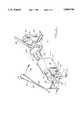
- FIG. 1is a top plan view of the preferred embodiment of the apparatus of the present invention showing the impacting of a distal extension member to a stem;
- FIG. 2is a perspective view of the preferred embodiment of the apparatus of the present invention illustating the impacting of a modular head being affixed to a prosthesis stem;
- FIG. 3is an elevational view of the preferred embodiment of the apparatus of the present invention showing the impacting of a distal extension member to a stem;
- FIG. 3Ais a perspective fragmentary view of the preferred embodiment of the apparatus of the present invention illustrating the actuator lever
- FIG. 4is a fragmentary view of the preferred embodiment of the apparatus of the present invention illustrating one of the support components
- FIG. 5is another fragmentary view of the preferred embodiment of the apparatus of the present invention illustrating another of the support components
- FIG. 6is a fragmentary elevational view illustrating an assembly of two prosthesis parts together, a shoulder stem and head portion;
- FIG. 7is a fragmentary view illustrating an assembly of a shoulder stem prosthesis portion to a handle used for manipulating the shoulder stem;
- FIG. 8is a fragmentary view illustrating an assembly of a shoulder stem prosthesis portion to a handle used for manipulating the shoulder stem;
- FIG. 9is a fragmentary view of the preferred embodiment of the apparatus of the present invention illustrating the handle of FIGS. 7 and 8 in a locked position;
- FIG. 10is a fragmentary view of the preferred embodiment of the apparatus of the present invention illustrating the handle of FIGS. 7 and 8 in an unlocked position.
- FIGS. 1-3 and 3Ashow generally the preferred embodiment of the apparatus of the present invention designated generally by the numeral 10.
- Prosthesis impactor apparatus 10includes a base member 11 that can be for example an instrument tray or an instrument tray lid. If an instrument tray or lid is used as base member 11, such can be constructed of structurally sound material such as stainless steel for example.
- the base member 11includes a periphery 12 and an upper surface 13 that is flat, defining a plane.
- Base member 11includes end portions 14, 15 and side portions 16, 17.
- the base member 11 upper surface 13supports a number of components that extend away from upper surface 13 as shown in FIGS. 1-3. These components include a first support 18 that is affixed by bolting or riveting for example at attachment 19 to base member 11. Support 18 provides a longitudinal bore 20 with a central longitudinal axis 29. During use, an impact driver tool 30 can be placed within bore 20 as shown in FIG. 3. It should be understood that the impact driver tool 30 is commercially available, sold by Smith & Nephew Richards of Memphis, Tenn.
- Cleat 21is fastened to upper surface 13 of base 11 using a bolted connection, rivets, welding or the like.
- Cleat 21can be generally rectangular in shape as shown and includes a number of attachment positions for affixing lever arm 40 (FIG. 3A) thereto.
- FIGS. 1 and 3two attachment positions 27, 28 are illustrated.
- Each attachment position 27, 28is defined by a pair of spaced apart slots that are generally U-shaped.
- the attachment position 27includes a pair of slots 22, 23.
- the attachment position 28includes a pair of slots 24, 25.
- the lever arm 40provides a lower transverse pin 26 that registers in the pair of slots 22,23 when attaching to the first attachment position 27. This first attachment position places the lever arm 40 transverse pin 26 closer to the support component 18.
- the lever 40has been attached to the second attachment position 28, a position that is farther away from the support component 18.
- These different attachment positions 27, 28allow the lever arm 40 to be used to activate the impact driver tool 30 from different positions depending upon the overall length of a modular prosthesis to be assembled.
- the impact driver tool 31includes an upper end portion 31 and a lower end portion 32.
- the lower end 32can provide a concave surface 33 for receiving one end portion of the handle 50 to be assembled.
- Lever arm 40can be L-shaped as shown in FIGS. 3 and 3A, providing straight sections 34, 35 and bent section 36.
- the upper most end portion of lever arm 40provides a handle 37 to be gripped by the surgeon during use.
- the lower end of lever arm 40provides a thickened portion 38 having a flat surface 39 for engaging the upper end 31 of impact driver tool 30 as shown in FIG. 3.
- a support 41defines a center support having an attachment 42 such as riveted or bolted to base 11.
- This support 41provides a cylindrically shaped opening 43 for example that can be used to support the mid-portion of a handle 50 to be assembled as shown in FIG. 3.
- a third support 44is in the form of an end support.
- the support 44can be sized and shaped to receive a handle member 50 that is used to manipulate certain prosthesis parts before and after assembly.
- the support 44has an attachment 45 to base 11 using a bolted, riveted, or welded connection for example.
- Support 44 as shown in FIG. 4includes a cube shaped portion 46 having an upper surface 47.
- a projection 48extends above surface 47.
- the projection 48includes a flat upper surface 49, a pair of flat side surfaces 51, 52, a curved side surface 53, and a pair of side flat surfaces 54, 55 that are on opposite sides of the curved side surface 53.
- the projection 49registers in a corresponding shaped recess 56 of handle 50 as shown in FIGS. 1, 3 and 7-10.
- the handle 50has a sliding trigger 57 that can be operated by the surgeon.
- the trigger 57has an end portion 58 that can be extended or retracted with respect to post 59.
- a cylindrically shaped opening through the post 59 and a portion of the handle 50accommodates the elongated cylindrically shaped end portion 58 as shown in FIG. 7.
- a prosthesis part 60such as for example a shoulder prosthesis part 60
- the surgeonpulls the trigger 57 in the direction of arrows in FIG. 10 to retract end portion 58 of trigger 57.
- a hemispherical recess 63 within socket 62receives the end portion 58 after the post 59 has registered in the socket 62.
- the useraccomplishes registration of end portion 58 into hemispherical recess 63 by releasing the trigger 57, allowing a return spring (not shown) to move the trigger into the extended position shown in FIG. 7.
- the part 60 and handle 50can be placed in the position as shown in FIGS. 1 and 3. In this position, the prosthesis part 60 extends through opening 43 of support 41.
- the handle 50attaches to support 44 at recess 48 at handle 50 as shown in FIGS. 7 and 8.
- the surgeoncan then select a desired modular extension part 71 for assembly to the stem 68 of prosthesis part 60.
- the prosthesis parts 60 and 71are joined at a taper lock connection 69. This is accomplished by providing each of the prosthesis parts 60 and 71 with tapered annular portions such as tapered annular male connector portion 70 and tapered annular female connection portion 72.
- tapered annular portionssuch as tapered annular male connector portion 70 and tapered annular female connection portion 72.
- the surgeonthen places impact driver tool 30 within the bore 20 of support 18 as shown in FIG. 3.
- the entire assembly of handle 50, prothesis part 60, extension prosthesis part 71, and impact driver 30are supported upon the plurality of supports 44, 41 and 18.
- the surgeonthen places the lever 40 in a desired position depending upon the overall length of the assembly of prosthesis parts 60, 71 and impact driver 30.
- the lever 40is positioned by placing the transverse pin 26 in a desired attachment position 27, 28 of cleat 21.
- the surgeonthen rotates the lever arm 40 toward the center support 41, engaging the upper end 31 of impact driver 30 with the thickened portion 38 of lever arm 40.
- the flat surface 39 of lever arm 40engages the upper end 31 of impact driver 30.
- This actioncompresses and shortens the impact driver 30 which triggers the impact load.
- the entire axial loadis carried by the base 11 and two components structurally attached thereto, namely the component 44 that supports and holds the handle 50 and the component lever arm 40 that is anchored to the cleat 21.
- FIGS. 2 and 5-6there is shown an assembly of a prosthesis head 86 to shoulder prosthesis part 60.
- the shoulder prosthesis part 60has a fin 64 with openings 66 as shown in FIGS. 6 and 7.
- a pin 82extends through auxiliary support 73 and through one of the openings 66 of fin 64 for supporting the prosthesis part 60 in the position shown in FIG. 6.
- the auxiliary support 73can be fastened to the base member 11 or simply braced against support 41 as shown in FIGS. 2 and 6.
- the auxiliary support 73has a lower surface 74, upper surface 75, diagonal surface 76, rear surface 77 and side surfaces 78.
- a longitudinally extending slot 79extends along the diagonal surface 76, approximately mid way between the side surfaces 78.
- the slot 79receives the fin 64 of prosthesis part 60 as shown in FIG. 6.
- a pair of transverse aligned openings 80, 81extend through the auxiliary support 73, communicating with the slot 79 as shown in FIG. 5.
- the openings 80,81receive pin 82 that can be manipulated using handle 84.
- the end 83 of the pin 82is first routed through the cylindrically shaped opening 80, then through an opening 66 through fin 64, and then through the cylindrically shaped opening 81.
- the head 86can be assembled thereto.
- the frustroconical socket 87 of head 86registers with and fits a similar corresponding frustroconical portion 61 of prothesis 60.
- the corresponding frustroconical portions 61, 87form a taper lock connection once loaded.
- the surgeonfirst loosely fits the head 86 to the prosthesis parts 60 by forming a loose connection between the socket 87 and frustroconical portion 61.
- FIG. 2the lower end 32 of impact driver 30 is placed against head 86 as shown.
- the surgeonthen rotates the lever arm 40 as shown by the arrow 88 in FIG. 2 firing impact driver 30 and forcing the lower end 32 against the head 86 with the impact force to assemble the components 86, 60 together.
- arrow 89illustrates the direction of axial load that is transmitted from the impact driver 30 to the head 86, forming a taper lock connection between the head 86 and prosthesis part 60.
- This assembly of the parts 86, 60is with a predictable axial load because the load is transmitted to the base member 11 via the support 41 and the lever arm 40 attached to cleat 21.
- auxiliary support 73could be provided for forming an attachment to a desired prosthesis part for holding that prosthesis part in alignment with another prosthesis part during impact loading using the apparatus of the present invention.
Landscapes
- Health & Medical Sciences (AREA)
- Transplantation (AREA)
- Orthopedic Medicine & Surgery (AREA)
- Vascular Medicine (AREA)
- Oral & Maxillofacial Surgery (AREA)
- Engineering & Computer Science (AREA)
- Biomedical Technology (AREA)
- Heart & Thoracic Surgery (AREA)
- Cardiology (AREA)
- Life Sciences & Earth Sciences (AREA)
- Animal Behavior & Ethology (AREA)
- General Health & Medical Sciences (AREA)
- Public Health (AREA)
- Veterinary Medicine (AREA)
- Physical Education & Sports Medicine (AREA)
- Prostheses (AREA)
Abstract
Description
1. Field of the Invention
The present invention relates to orthopedic surgical instruments and more particularly relates to an improved method and apparatus for assembling modular orthopedic prosthesis components using an impactor tool or impact driver. Even more particularly, the present invention relates to an improved impact driver apparatus for assembling modular orthopedic prosthesis parts wherein a base member and spaced apart supports carry all of the axial load transmitted from the impact driver to the prosthesis so that the axial load is reproducible and accurate notwithstanding the rigidity of any underlying surface adjacent the base member.
2. General Background
Various orthopedic prosthetic devices are used to replace diseased tissue of the patient, for example at a joint such as the knee, hip or shoulder. Various orthopedic prosthetic devices include two or more components that can be assembled together to define the final prosthesis. These "modular" prosthetic devices are sometimes assembled using a taper lock or wedge lock connection. For example, the DeMane U.S. Pat. Nos. 4,995,883 and 5,108,452 relate to a modular hip prosthesis and its method of assembly. In the DeMane '883 and '452 patents, taper lock connections are used to assemble a distal sleeve to a hip prosthesis, and the assembly of a modular sphere or ball with a taper lock or wedge lock connection to an extension trunion.
One of the problems with modular prosthetic devices is the problem of accurate and reproducible assembly loads. In orthopedic surgery, impact driver instruments and the prosthesis to be assembled are usually supported upon an operating room table or like supporting surface. The rigidity of such an underlying support can vary from one operating room to the next. However, most impact driver tools only provide a single load setting. If the impact driver tool is supported in the hand of a user and the prosthesis braced against an operating room table, part of the load is absorbed by the underlying operating room table. This procedure can destroy predictability of the axial load actually transmitted directly to the modular prosthesis joint. When a taper lock connection is loaded in this somewhat unpredictable fashion, it is possible that a particular prosthesis could become disassembled or loose after surgical implantation.
The present invention provides a method and apparatus for transmitting axial load from an impact driver tool to a taper lock assembled modular prosthesis so that the axial load is reproducible and accurate notwithstanding the rigidity of the underlying surface such as a operating room table or the like.
The apparatus of the present invention provides a base member defining a plane and having a plurality of components that extend away from the plane on one side of the base member.
In the preferred embodiment, the base member is an instrument tray or an instrument tray lid. The impact driver, the modular prosthesis and prosthesis extension parts can be packaged in an instrument tray. The tray or lid can then function as the support for axial load transfer during impact driving.
The components extending from the base member include a pair of spaced apart supports. An impact driver tool can be removably attached to these supports. The components also include an impactor tool actuator that can be a lever pivotally attached to the base member.
A pair of prosthesis parts are connectable at a taper lock connection defined by respective tapered annular portions of the prosthesis parts. These respective tapered annular portions are placed end to end with tapered annular portions engaged.
The prosthesis parts are then held adjacent the base in axial alignment and with the impact driver engaging one of the two prosthesis parts. This assembly of prosthesis parts and impact driver is supported adjacent the tray or base, generally in-between the pair of spaced apart supports.
The actuator can then be used to activate the impact driver to thereby transmit a load to the prosthesis parts for driving the parts together at the taper lock connection. The spaced apart supports hold opposite end portions of the entire assembly of prosthesis parts and impact driver.
The base member and its components (including the supports and the actuator) carry all of the axial load transmitted from the impact driver to the prosthesis. In the fashion, the axial load is reproducible and accurate notwithstanding the rigidity of any underlying surfaces adjacent the base member. This result follows because then the base member is placed on the underlying surface whereas the load is transferred axially relative to the base member in a direction generally parallel to the underlying surface. A load is thus transmitted through the base member and its components, providing a constant load transmission system that is reproducible and accurate.
For a further understanding of the nature and objects of the present invention, reference should be had to the following detailed description, taken in conjunction with the accompanying drawings, in which like parts are given like reference numerals, and wherein:
FIG. 1 is a top plan view of the preferred embodiment of the apparatus of the present invention showing the impacting of a distal extension member to a stem;
FIG. 2 is a perspective view of the preferred embodiment of the apparatus of the present invention illustating the impacting of a modular head being affixed to a prosthesis stem;
FIG. 3 is an elevational view of the preferred embodiment of the apparatus of the present invention showing the impacting of a distal extension member to a stem;
FIG. 3A is a perspective fragmentary view of the preferred embodiment of the apparatus of the present invention illustrating the actuator lever;
FIG. 4 is a fragmentary view of the preferred embodiment of the apparatus of the present invention illustrating one of the support components;
FIG. 5 is another fragmentary view of the preferred embodiment of the apparatus of the present invention illustrating another of the support components;
FIG. 6 is a fragmentary elevational view illustrating an assembly of two prosthesis parts together, a shoulder stem and head portion;
FIG. 7 is a fragmentary view illustrating an assembly of a shoulder stem prosthesis portion to a handle used for manipulating the shoulder stem;
FIG. 8 is a fragmentary view illustrating an assembly of a shoulder stem prosthesis portion to a handle used for manipulating the shoulder stem;
FIG. 9 is a fragmentary view of the preferred embodiment of the apparatus of the present invention illustrating the handle of FIGS. 7 and 8 in a locked position;
FIG. 10 is a fragmentary view of the preferred embodiment of the apparatus of the present invention illustrating the handle of FIGS. 7 and 8 in an unlocked position.
FIGS. 1-3 and 3A show generally the preferred embodiment of the apparatus of the present invention designated generally by the numeral 10. Prosthesis impactor apparatus 10 includes a base member 11 that can be for example an instrument tray or an instrument tray lid. If an instrument tray or lid is used as base member 11, such can be constructed of structurally sound material such as stainless steel for example.
The base member 11 includes aperiphery 12 and anupper surface 13 that is flat, defining a plane. Base member 11 includesend portions side portions 16, 17.
The base member 11upper surface 13 supports a number of components that extend away fromupper surface 13 as shown in FIGS. 1-3. These components include afirst support 18 that is affixed by bolting or riveting for example atattachment 19 to base member 11.Support 18 provides alongitudinal bore 20 with a centrallongitudinal axis 29. During use, animpact driver tool 30 can be placed withinbore 20 as shown in FIG. 3. It should be understood that theimpact driver tool 30 is commercially available, sold by Smith & Nephew Richards of Memphis, Tenn.
Another component that extends away fromupper surface 13 of base 11 is cleat 21. Cleat 21 is fastened toupper surface 13 of base 11 using a bolted connection, rivets, welding or the like. Cleat 21 can be generally rectangular in shape as shown and includes a number of attachment positions for affixing lever arm 40 (FIG. 3A) thereto. In FIGS. 1 and 3, twoattachment positions attachment position attachment position 27 includes a pair ofslots 22, 23. Theattachment position 28 includes a pair ofslots 24, 25. Thelever arm 40 provides a lowertransverse pin 26 that registers in the pair ofslots 22,23 when attaching to thefirst attachment position 27. This first attachment position places thelever arm 40transverse pin 26 closer to thesupport component 18.
In FIG. 3, thelever 40 has been attached to thesecond attachment position 28, a position that is farther away from thesupport component 18. These different attachment positions 27, 28 allow thelever arm 40 to be used to activate theimpact driver tool 30 from different positions depending upon the overall length of a modular prosthesis to be assembled.
The impact driver tool 31 includes an upper end portion 31 and alower end portion 32. Thelower end 32 can provide aconcave surface 33 for receiving one end portion of thehandle 50 to be assembled.
Asupport 41 defines a center support having anattachment 42 such as riveted or bolted to base 11. Thissupport 41 provides a cylindrically shapedopening 43 for example that can be used to support the mid-portion of ahandle 50 to be assembled as shown in FIG. 3.
Athird support 44 is in the form of an end support. Thesupport 44 can be sized and shaped to receive ahandle member 50 that is used to manipulate certain prosthesis parts before and after assembly. Thesupport 44 has anattachment 45 to base 11 using a bolted, riveted, or welded connection for example.Support 44 as shown in FIG. 4 includes a cube shapedportion 46 having anupper surface 47. Aprojection 48 extends abovesurface 47. Theprojection 48 includes a flatupper surface 49, a pair of flat side surfaces 51, 52, acurved side surface 53, and a pair of sideflat surfaces curved side surface 53. Theprojection 49 registers in a corresponding shapedrecess 56 ofhandle 50 as shown in FIGS. 1, 3 and 7-10.
In FIG. 7-10, thehandle 50 has a slidingtrigger 57 that can be operated by the surgeon. Thetrigger 57 has anend portion 58 that can be extended or retracted with respect to post 59. A cylindrically shaped opening through the post 59 and a portion of thehandle 50 accommodates the elongated cylindricallyshaped end portion 58 as shown in FIG. 7.
In order to form a connection between thehandle 50 and aprosthesis part 60 such as for example ashoulder prosthesis part 60, the surgeon pulls thetrigger 57 in the direction of arrows in FIG. 10 to retractend portion 58 oftrigger 57. This allows post 58 to be placed within socket 62 offrustroconical connector 61. A hemispherical recess 63 within socket 62 receives theend portion 58 after the post 59 has registered in the socket 62. The user accomplishes registration ofend portion 58 into hemispherical recess 63 by releasing thetrigger 57, allowing a return spring (not shown) to move the trigger into the extended position shown in FIG. 7.
Once the user so assembles handle 50 andprosthesis part 60, thepart 60 and handle 50 can be placed in the position as shown in FIGS. 1 and 3. In this position, theprosthesis part 60 extends through opening 43 ofsupport 41. Thehandle 50 attaches to support 44 atrecess 48 athandle 50 as shown in FIGS. 7 and 8.
The surgeon can then select a desired modular extension part 71 for assembly to thestem 68 ofprosthesis part 60. Theprosthesis parts 60 and 71 are joined at a taper lock connection 69. This is accomplished by providing each of theprosthesis parts 60 and 71 with tapered annular portions such as tapered annular male connector portion 70 and tapered annular female connection portion 72. Such a "taper lock" connection can be seen for example in the DeMane U.S. Pat. Nos. 4,995,883 and 5,108,452 incorporated herein by reference.
After the selected stem or extension member prosthesis part 71 is attached to theprosthesis part 60, the surgeon then placesimpact driver tool 30 within thebore 20 ofsupport 18 as shown in FIG. 3. The entire assembly ofhandle 50,prothesis part 60, extension prosthesis part 71, andimpact driver 30 are supported upon the plurality ofsupports lever 40 in a desired position depending upon the overall length of the assembly ofprosthesis parts 60, 71 andimpact driver 30. Thelever 40 is positioned by placing thetransverse pin 26 in a desiredattachment position lever arm 40 toward thecenter support 41, engaging the upper end 31 ofimpact driver 30 with the thickenedportion 38 oflever arm 40. Theflat surface 39 oflever arm 40 engages the upper end 31 ofimpact driver 30. This action compresses and shortens theimpact driver 30 which triggers the impact load. During this transmission of the impact load to theprosthesis parts 60, 71 the entire axial load is carried by the base 11 and two components structurally attached thereto, namely thecomponent 44 that supports and holds thehandle 50 and thecomponent lever arm 40 that is anchored to the cleat 21.
In FIGS. 2 and 5-6, there is shown an assembly of aprosthesis head 86 toshoulder prosthesis part 60. The shoulder prosthesispart 60 has afin 64 withopenings 66 as shown in FIGS. 6 and 7. In FIGS. 2 and 5-6, apin 82 extends throughauxiliary support 73 and through one of theopenings 66 offin 64 for supporting theprosthesis part 60 in the position shown in FIG. 6. Theauxiliary support 73 can be fastened to the base member 11 or simply braced againstsupport 41 as shown in FIGS. 2 and 6.
Theauxiliary support 73 has alower surface 74,upper surface 75,diagonal surface 76,rear surface 77 and side surfaces 78. A longitudinally extendingslot 79 extends along thediagonal surface 76, approximately mid way between the side surfaces 78. Theslot 79 receives thefin 64 ofprosthesis part 60 as shown in FIG. 6. A pair of transverse alignedopenings auxiliary support 73, communicating with theslot 79 as shown in FIG. 5. Theopenings pin 82 that can be manipulated usinghandle 84. Theend 83 of thepin 82 is first routed through the cylindrically shapedopening 80, then through anopening 66 throughfin 64, and then through the cylindrically shapedopening 81.
After theprosthesis part 60 is secured as shown in FIG. 6, thehead 86 can be assembled thereto. Thefrustroconical socket 87 ofhead 86 registers with and fits a similar correspondingfrustroconical portion 61 ofprothesis 60. Thecorresponding frustroconical portions head 86 to theprosthesis parts 60 by forming a loose connection between thesocket 87 andfrustroconical portion 61.
In FIG. 2, thelower end 32 ofimpact driver 30 is placed againsthead 86 as shown. The surgeon then rotates thelever arm 40 as shown by thearrow 88 in FIG. 2firing impact driver 30 and forcing thelower end 32 against thehead 86 with the impact force to assemble thecomponents impact driver 30 to thehead 86, forming a taper lock connection between thehead 86 andprosthesis part 60. This assembly of theparts support 41 and thelever arm 40 attached to cleat 21.
Within the teaching of the present invention, otherauxiliary support 73 could be provided for forming an attachment to a desired prosthesis part for holding that prosthesis part in alignment with another prosthesis part during impact loading using the apparatus of the present invention.
The following table lists the parts numbers and parts descriptions as used herein and in the drawings attached hereto.
______________________________________ Part Number Description ______________________________________ 10 prosthesis impactor apparatus 11base member 12periphery 13upper surface 14end 15end 16 side 17side 18end support 19attachment 20 longitudinal bore 21 cleat 22slot 23 slot 24slot 25slot 26transverse pin 27attachment position 28attachment position 29axis 30 impact driver tool 31upper end 32lower end 33concavity 34straight section 35straight section 36bent section 37 handle 38 thickenedportion 39flat surface 40lever 41center support 42attachment 43opening 44end support 45attachment 46cube 47upper surface 48projection 49 upperflat surface 50 handle 51flat side 52flat side 53curved side 54flat side 55flat side 56recess 57 slidingtrigger 58 end portion 59post 60prosthesis part 61 frustroconical connector 62 socket 63hemispherical recess 64fin 65fin 66 opening 67opening 68 cylindrical stem 69 taper lock connection 70 male connector 71 extension part 72female connector 73auxiliary support 74lower surface 75upper surface 76diagonal surface 77rear surface 78 side surfaces 79slot 80transverse opening 81transverse opening 82pin 83end 84handle 85arrows 86head 87frustroconical socket 88 arrow 89 arrow ______________________________________
Because many varying and different embodiments may be made within the scope of the inventive concept herein taught, and because many modifications may be made in the embodiments herein detailed in accordance with the descriptive requirement of the law, it is to be understood that the details herein are to be interpreted as illustrative and not in a limiting sense.
Claims (10)
1. Modular orthopedic prosthesis parts and an impactor apparatus for assembling modular orthopedic prosthesis parts comprising;
a) a base member defining a plane and having a plurality of components extending away from said plane;
b) said components including a pair of spaced apart supports;
c) an impactor driver tool removably supported upon said supports in a fixed position relative to the base member;
d) said components including an impactor driver tool actuator that pivotally attaches to the base member;
e) the modular prosthesis parts being connectable at a taper lock connection defined by respective tapered annular portions of the prosthesis parts;
f) means for holding the prosthesis parts adjacent the base in axial alignment with the impact driver, in between the pair of supports; and
g) said actuator defining means for activating the impact driver tool to transmit a load to the prosthesis parts for driving said parts together at the taper lock connection;
h) wherein the spaced apart supports hold opposite end portions of the assembly of prosthesis parts and impact driver;
i) wherein the base member and its components carry axial load transmitted from the impact driver to the prosthesis so that the axial load is reproducible and accurate notwithstanding the rigidity of any underlying surface adjacent the base member.
2. The apparatus of claim 1 wherein said impactor tool is an elongated tool body having a trigger at one end portion thereof.
3. The apparatus of claim 1 wherein the components include a pivot on the base and a lever that rotates about the pivot, said lever being positioned to engage one end portion of the impactor when the impactor is held by the components and one of the components axially opposes force applied to the impactor using the lever.
4. The apparatus of claim 1 wherein one of the components is a support with an opening therethrough.
5. The apparatus of claim 1 wherein there are a plurality of pivots and the actuator is a lever that can be selectively attached to one of the pivots.
6. The apparatus of claim 1 wherein the base is a metal plate member and the supports are of a plastic material.
7. The apparatus of claim 1 wherein the prosthetic parts include a humeral prosthesis member with a stem, an extension sleeve with a bore that fits over the stem, and a head that connects to the stem generally opposite the extension sleeve.
8. The apparatus of claim 1 wherein the prosthesis is adapted for placement in the intramedullary canal of a patient.
9. The apparatus of claim 1 wherein the prosthesis includes a stem and an extension sleeve, each having cooperating frustroconical portions that connect to define a taper lock connection.
10. A method of joining a pair of prosthesis parts that are connectable at a taper lock connection defined by respective tapered annular portions of the prosthesis parts comprising the steps of:
a) aligning the respective tapered annular portions of the prosthesis parts;
b) fitting the respective annular tapered portions together;
c) holding the respective tapered annular portions together with spaced apart components anchored to a base member;
d) supporting an impact driver in a position that aligns the central axis of the impact driver with the respective annular portions;
e) using one of the components to hold one end of the assembly of prosthesis parts opposite the impact driver;
f) using a second of the components to hold a second end of the assembly of prosthesis parts and the impact driver;
g) compressing the prosthesis parts together with the impact driver;
h) wherein in step "g", one of the components is movably mounted to the base member in relation to the other component for activating the impact driver, so that when the impact driver is activated, an impact load is transmitted to the respective annular portions.
Priority Applications (1)
| Application Number | Priority Date | Filing Date | Title |
|---|---|---|---|
| US08/514,798US5800546A (en) | 1995-08-14 | 1995-08-14 | Impactor apparatus for assembling modular orthopedic prosthesis components |
Applications Claiming Priority (1)
| Application Number | Priority Date | Filing Date | Title |
|---|---|---|---|
| US08/514,798US5800546A (en) | 1995-08-14 | 1995-08-14 | Impactor apparatus for assembling modular orthopedic prosthesis components |
Publications (1)
| Publication Number | Publication Date |
|---|---|
| US5800546Atrue US5800546A (en) | 1998-09-01 |
Family
ID=24048744
Family Applications (1)
| Application Number | Title | Priority Date | Filing Date |
|---|---|---|---|
| US08/514,798Expired - Fee RelatedUS5800546A (en) | 1995-08-14 | 1995-08-14 | Impactor apparatus for assembling modular orthopedic prosthesis components |
Country Status (1)
| Country | Link |
|---|---|
| US (1) | US5800546A (en) |
Cited By (36)
| Publication number | Priority date | Publication date | Assignee | Title |
|---|---|---|---|---|
| FR2814061A1 (en)* | 2000-09-21 | 2002-03-22 | Sulzer Orthopedie S A | IMPACTOR FOR THE ORTHOPEDIC AREA |
| US6626913B1 (en) | 1999-03-03 | 2003-09-30 | Smith & Nephew, Inc. | Methods, systems, and instruments for inserting prosthetic implants |
| US6709439B2 (en) | 2001-10-30 | 2004-03-23 | Depuy Spine, Inc. | Slaphammer tool |
| US20040064145A1 (en)* | 2002-09-30 | 2004-04-01 | Ball Robert J. | Force specific impacting device |
| US20040127862A1 (en)* | 2002-12-31 | 2004-07-01 | Bubb Stephen K. | Tissue closure treatment system and method with externally-applied patient interface |
| US6814738B2 (en) | 2001-01-23 | 2004-11-09 | Depuy Acromed, Inc. | Medical impacting device and system |
| US20050119666A1 (en)* | 2003-11-28 | 2005-06-02 | Bubb Stephen K. | Orthopedic and dental implant system and method |
| US20050268425A1 (en)* | 2004-04-20 | 2005-12-08 | Clemons William E Sr | Surface cleaner |
| US20060247774A1 (en)* | 2005-04-29 | 2006-11-02 | Gil Carlos E | Spinal implant |
| US20070065545A1 (en)* | 2005-09-20 | 2007-03-22 | Terry Vovan | Multi-topping tray container system |
| US20070173856A1 (en)* | 2006-01-25 | 2007-07-26 | Parker Brad A | Split thread orthopaedic implant impactor |
| US7351250B2 (en) | 2002-08-21 | 2008-04-01 | Kci Licensing, Inc. | Circumferential medical closure device and method |
| US7381211B2 (en) | 2002-08-21 | 2008-06-03 | Kci Licensing, Inc. | Medical closure screen device and method |
| US7410495B2 (en) | 2002-08-21 | 2008-08-12 | Kci Licensing, Inc. | Medical closure clip system and method |
| US7413571B2 (en) | 2002-08-21 | 2008-08-19 | Kci Licensing, Inc. | Flexible medical closure screen and method |
| US7413570B2 (en) | 2002-08-21 | 2008-08-19 | Kci Licensing, Inc. | Medical closure screen installation systems and methods |
| US20080255565A1 (en)* | 2006-11-20 | 2008-10-16 | Fletcher Henry H | Broach handle for minimally invasive hip replacement surgery |
| US20100076438A1 (en)* | 2007-12-20 | 2010-03-25 | Depuy Products, Inc. | Keel punch impactor with connection device |
| US7976519B2 (en) | 2002-12-31 | 2011-07-12 | Kci Licensing, Inc. | Externally-applied patient interface system and method |
| US8062331B2 (en) | 2002-08-21 | 2011-11-22 | Kci Licensing, Inc. | Internal and external medical closure screen systems and methods |
| US8128703B2 (en) | 2007-09-28 | 2012-03-06 | Depuy Products, Inc. | Fixed-bearing knee prosthesis having interchangeable components |
| US8133231B2 (en) | 2004-07-06 | 2012-03-13 | Tyco Healthcare Group Lp | Instrument kit and method for performing meniscal repair |
| US8287601B2 (en) | 2010-09-30 | 2012-10-16 | Depuy Products, Inc. | Femoral component of a knee prosthesis having an angled cement pocket |
| US8317870B2 (en) | 2010-09-30 | 2012-11-27 | Depuy Products, Inc. | Tibial component of a knee prosthesis having an angled cement pocket |
| EP2777634A1 (en)* | 2013-03-14 | 2014-09-17 | DePuy (Ireland) | Assembly tool for orthopaedic prosthesis components |
| US9011547B2 (en) | 2010-01-21 | 2015-04-21 | Depuy (Ireland) | Knee prosthesis system |
| US9204967B2 (en) | 2007-09-28 | 2015-12-08 | Depuy (Ireland) | Fixed-bearing knee prosthesis having interchangeable components |
| US9398956B2 (en) | 2007-09-25 | 2016-07-26 | Depuy (Ireland) | Fixed-bearing knee prosthesis having interchangeable components |
| US9408956B2 (en) | 2010-09-24 | 2016-08-09 | Kci Licensing, Inc. | Cellular control and tissue regeneration systems and methods |
| US9456930B2 (en) | 2011-07-12 | 2016-10-04 | Kci Licensing, Inc. | Topical vacuum-press surgical incisional dressings, surgical adjuncts, hybrids and composites |
| US9569566B2 (en) | 2011-12-12 | 2017-02-14 | Zam Research Llc | Simulation and control system and method using contact, pressure waves and factor controls for cell regeneration, tissue closure and related applications |
| DE102016119674A1 (en)* | 2016-10-14 | 2018-04-19 | Silony Medical International AG | Mounting device for hip stem prosthesis |
| US20180116747A1 (en)* | 2016-10-31 | 2018-05-03 | Epix Orthopaedics, Inc. | Sterilization tray for facilitating attachment of implant insertion device to implantable device, related apparatus and methods |
| US9968488B2 (en) | 2012-11-12 | 2018-05-15 | Kci Usa, Inc. | Externally-applied patient interface system and method |
| US10363344B2 (en) | 2002-12-31 | 2019-07-30 | Kci Licensing, Inc. | Externally-applied patient interface system and method with a controlled region for implanted or buried bio-reactor |
| US10492956B2 (en) | 2013-03-15 | 2019-12-03 | Kci Licensing, Inc. | Topical vacuum-press surgical incisional dressings, surgical adjuncts, hybrids and composites |
Citations (5)
| Publication number | Priority date | Publication date | Assignee | Title |
|---|---|---|---|---|
| US4993410A (en)* | 1989-05-01 | 1991-02-19 | Kimsey Timothy P | Prosthetic removal device |
| US4995883A (en)* | 1989-02-08 | 1991-02-26 | Smith & Nephew Richards Inc. | Modular hip prosthesis |
| US5108452A (en)* | 1989-02-08 | 1992-04-28 | Smith & Nephew Richards Inc. | Modular hip prosthesis |
| US5314479A (en)* | 1986-08-15 | 1994-05-24 | Depuy Inc. | Modular prosthesis |
| US5470336A (en)* | 1990-08-10 | 1995-11-28 | Ling; Robin S. M. | System for performing hip prosthesis revision surgery |
- 1995
- 1995-08-14USUS08/514,798patent/US5800546A/ennot_activeExpired - Fee Related
Patent Citations (5)
| Publication number | Priority date | Publication date | Assignee | Title |
|---|---|---|---|---|
| US5314479A (en)* | 1986-08-15 | 1994-05-24 | Depuy Inc. | Modular prosthesis |
| US4995883A (en)* | 1989-02-08 | 1991-02-26 | Smith & Nephew Richards Inc. | Modular hip prosthesis |
| US5108452A (en)* | 1989-02-08 | 1992-04-28 | Smith & Nephew Richards Inc. | Modular hip prosthesis |
| US4993410A (en)* | 1989-05-01 | 1991-02-19 | Kimsey Timothy P | Prosthetic removal device |
| US5470336A (en)* | 1990-08-10 | 1995-11-28 | Ling; Robin S. M. | System for performing hip prosthesis revision surgery |
Cited By (60)
| Publication number | Priority date | Publication date | Assignee | Title |
|---|---|---|---|---|
| US6626913B1 (en) | 1999-03-03 | 2003-09-30 | Smith & Nephew, Inc. | Methods, systems, and instruments for inserting prosthetic implants |
| EP1190687A1 (en)* | 2000-09-21 | 2002-03-27 | Sulzer Orthopedie S.A. | Impactor for use in orthopaedics |
| FR2814061A1 (en)* | 2000-09-21 | 2002-03-22 | Sulzer Orthopedie S A | IMPACTOR FOR THE ORTHOPEDIC AREA |
| US6814738B2 (en) | 2001-01-23 | 2004-11-09 | Depuy Acromed, Inc. | Medical impacting device and system |
| US6709439B2 (en) | 2001-10-30 | 2004-03-23 | Depuy Spine, Inc. | Slaphammer tool |
| US7413571B2 (en) | 2002-08-21 | 2008-08-19 | Kci Licensing, Inc. | Flexible medical closure screen and method |
| US7351250B2 (en) | 2002-08-21 | 2008-04-01 | Kci Licensing, Inc. | Circumferential medical closure device and method |
| US8070773B2 (en) | 2002-08-21 | 2011-12-06 | Kci Licensing, Inc. | Medical closure methods and screen devices |
| US8062331B2 (en) | 2002-08-21 | 2011-11-22 | Kci Licensing, Inc. | Internal and external medical closure screen systems and methods |
| US7413570B2 (en) | 2002-08-21 | 2008-08-19 | Kci Licensing, Inc. | Medical closure screen installation systems and methods |
| US8123781B2 (en) | 2002-08-21 | 2012-02-28 | Kci Licensing, Inc. | Screen devices and methods for closing tissue separations |
| US7410495B2 (en) | 2002-08-21 | 2008-08-12 | Kci Licensing, Inc. | Medical closure clip system and method |
| US7381211B2 (en) | 2002-08-21 | 2008-06-03 | Kci Licensing, Inc. | Medical closure screen device and method |
| EP1405617A3 (en)* | 2002-09-30 | 2005-08-03 | DePuy Products, Inc. | Force specific impacting device |
| US7172598B2 (en) | 2002-09-30 | 2007-02-06 | Depuy Products, Inc. | Force specific impacting device |
| US20040064145A1 (en)* | 2002-09-30 | 2004-04-01 | Ball Robert J. | Force specific impacting device |
| US6951553B2 (en) | 2002-12-31 | 2005-10-04 | Kci Licensing, Inc | Tissue closure treatment system and method with externally-applied patient interface |
| US10363344B2 (en) | 2002-12-31 | 2019-07-30 | Kci Licensing, Inc. | Externally-applied patient interface system and method with a controlled region for implanted or buried bio-reactor |
| US20040127863A1 (en)* | 2002-12-31 | 2004-07-01 | Bubb Stephen K. | Tissue closure treatment system, patient interface and method |
| US6936037B2 (en) | 2002-12-31 | 2005-08-30 | Kci Licensing, Inc. | Tissue closure treatment system, patient interface and method |
| US8956335B2 (en) | 2002-12-31 | 2015-02-17 | Kci Licensing, Inc. | Externaly-applied patient interface system and method |
| US7976519B2 (en) | 2002-12-31 | 2011-07-12 | Kci Licensing, Inc. | Externally-applied patient interface system and method |
| US20040127862A1 (en)* | 2002-12-31 | 2004-07-01 | Bubb Stephen K. | Tissue closure treatment system and method with externally-applied patient interface |
| US7326217B2 (en) | 2003-11-28 | 2008-02-05 | Bubb Stephen K | Orthopedic and dental implant system and method |
| US20050119666A1 (en)* | 2003-11-28 | 2005-06-02 | Bubb Stephen K. | Orthopedic and dental implant system and method |
| US20050268425A1 (en)* | 2004-04-20 | 2005-12-08 | Clemons William E Sr | Surface cleaner |
| US8133231B2 (en) | 2004-07-06 | 2012-03-13 | Tyco Healthcare Group Lp | Instrument kit and method for performing meniscal repair |
| US20060247774A1 (en)* | 2005-04-29 | 2006-11-02 | Gil Carlos E | Spinal implant |
| US8147547B2 (en) | 2005-04-29 | 2012-04-03 | Warsaw Orthopedic, Inc. | Spinal implant |
| US20070065545A1 (en)* | 2005-09-20 | 2007-03-22 | Terry Vovan | Multi-topping tray container system |
| US7621921B2 (en)* | 2006-01-25 | 2009-11-24 | Symmetry Medical, Inc | Split thread orthopaedic implant impactor |
| US20070173856A1 (en)* | 2006-01-25 | 2007-07-26 | Parker Brad A | Split thread orthopaedic implant impactor |
| US20080255565A1 (en)* | 2006-11-20 | 2008-10-16 | Fletcher Henry H | Broach handle for minimally invasive hip replacement surgery |
| US9398956B2 (en) | 2007-09-25 | 2016-07-26 | Depuy (Ireland) | Fixed-bearing knee prosthesis having interchangeable components |
| US9204967B2 (en) | 2007-09-28 | 2015-12-08 | Depuy (Ireland) | Fixed-bearing knee prosthesis having interchangeable components |
| US8128703B2 (en) | 2007-09-28 | 2012-03-06 | Depuy Products, Inc. | Fixed-bearing knee prosthesis having interchangeable components |
| US20100076438A1 (en)* | 2007-12-20 | 2010-03-25 | Depuy Products, Inc. | Keel punch impactor with connection device |
| US9011547B2 (en) | 2010-01-21 | 2015-04-21 | Depuy (Ireland) | Knee prosthesis system |
| US9408956B2 (en) | 2010-09-24 | 2016-08-09 | Kci Licensing, Inc. | Cellular control and tissue regeneration systems and methods |
| US8287601B2 (en) | 2010-09-30 | 2012-10-16 | Depuy Products, Inc. | Femoral component of a knee prosthesis having an angled cement pocket |
| US8845746B2 (en) | 2010-09-30 | 2014-09-30 | Depuy (Ireland) | Femoral component of a knee prosthesis having an angled posterior cement pocket |
| US9724202B2 (en) | 2010-09-30 | 2017-08-08 | Depuy Ireland Unlimited Company | Femoral component of a knee prosthesis having an angled cement pocket |
| US8317870B2 (en) | 2010-09-30 | 2012-11-27 | Depuy Products, Inc. | Tibial component of a knee prosthesis having an angled cement pocket |
| US9456930B2 (en) | 2011-07-12 | 2016-10-04 | Kci Licensing, Inc. | Topical vacuum-press surgical incisional dressings, surgical adjuncts, hybrids and composites |
| US9569566B2 (en) | 2011-12-12 | 2017-02-14 | Zam Research Llc | Simulation and control system and method using contact, pressure waves and factor controls for cell regeneration, tissue closure and related applications |
| US10857038B2 (en) | 2012-11-12 | 2020-12-08 | Kci Licensing, Inc. | Externally-applied patient interface system and method |
| US9968488B2 (en) | 2012-11-12 | 2018-05-15 | Kci Usa, Inc. | Externally-applied patient interface system and method |
| EP2777634A1 (en)* | 2013-03-14 | 2014-09-17 | DePuy (Ireland) | Assembly tool for orthopaedic prosthesis components |
| JP2014176691A (en)* | 2013-03-14 | 2014-09-25 | Depuy (Ireland) | Assembly tool for use in assembling orthopedic prosthetic components |
| CN104042371B (en)* | 2013-03-14 | 2017-08-15 | 德普伊爱尔兰无限公司 | For the assembling tool used in assembling orthopedic technical aid part |
| US9149897B2 (en) | 2013-03-14 | 2015-10-06 | Depuy (Ireland) | Assembly tool for use in assembling orthopaedic prosthetic components |
| AU2014201273B2 (en)* | 2013-03-14 | 2019-02-28 | Depuy Ireland Unlimited Company | Assembly tool for use in assembling orthopaedic prosthetic components |
| US10492956B2 (en) | 2013-03-15 | 2019-12-03 | Kci Licensing, Inc. | Topical vacuum-press surgical incisional dressings, surgical adjuncts, hybrids and composites |
| DE102016119674A1 (en)* | 2016-10-14 | 2018-04-19 | Silony Medical International AG | Mounting device for hip stem prosthesis |
| US20190314106A1 (en)* | 2016-10-31 | 2019-10-17 | Epix Orthopaedics, Inc. | Method for preparing implantable device for use |
| CN110022783A (en)* | 2016-10-31 | 2019-07-16 | Epix整形外科股份有限公司 | For being attached to the sterilization tray of implantable utensil convenient for implantation material insertion device |
| US20180116747A1 (en)* | 2016-10-31 | 2018-05-03 | Epix Orthopaedics, Inc. | Sterilization tray for facilitating attachment of implant insertion device to implantable device, related apparatus and methods |
| US10945804B2 (en)* | 2016-10-31 | 2021-03-16 | Epix Orthopaedics, Inc. | Sterilization tray for holding implant insertion device for attachment to implantable device and related devices |
| CN110022783B (en)* | 2016-10-31 | 2023-03-28 | Epix整形外科股份有限公司 | Sterilization tray for facilitating attachment of an implant insertion appliance to an implantable appliance |
| US11723743B2 (en)* | 2016-10-31 | 2023-08-15 | Epix Orthopaedics, Inc. | Method for preparing implantable device for use |
Similar Documents
| Publication | Publication Date | Title |
|---|---|---|
| US5800546A (en) | Impactor apparatus for assembling modular orthopedic prosthesis components | |
| US7993348B2 (en) | Curved acetabular positioner, impactor and reamer handle | |
| AU623970B2 (en) | Releasable orthopedic broach handle apparatus | |
| US7625406B2 (en) | Elbow prosthesis | |
| US6168595B1 (en) | Modular intramedullary fixation system and insertion instrumentation | |
| US8801724B2 (en) | Device for placing or removing joints or joint sockets | |
| US5976147A (en) | Modular instrumentation for bone preparation and implant trial reduction of orthopedic implants | |
| US5540697A (en) | Prosthetic socket installation apparatus and method | |
| EP1707160B1 (en) | Controlled force impacting device | |
| US6786931B2 (en) | Device, system and method for separation of modular orthopaedic elements | |
| CA2482198A1 (en) | Surgical device with malleable shaft | |
| US11173047B2 (en) | Surgical instrument with angled drive shaft | |
| EP0558203A1 (en) | Modular trial instrument with interlock mechanism | |
| JP2017029771A (en) | Double offset surgical instrument | |
| KR20010013336A (en) | Modular prosthesis | |
| JP5654614B2 (en) | Implant placement device | |
| JPH06169930A (en) | Thigh bone artificial outfit grasping/ driving tool and method for implantation using said tool | |
| JP2004518453A (en) | Devices, instruments and prostheses for sutureless anastomosis | |
| WO1996002202A1 (en) | Multi-section intramedullary nail | |
| US5350381A (en) | Orthopedic broach handle apparatus | |
| US7608112B1 (en) | Hip arthroplasty trialing apparatus and method | |
| US20140066942A1 (en) | Force Dissipating Impactor Device | |
| US6520966B1 (en) | Setting instrument for a tibia part of a knee joint prosthesis | |
| US7172598B2 (en) | Force specific impacting device | |
| KR200459347Y1 (en) | A Broachhandle |
Legal Events
| Date | Code | Title | Description |
|---|---|---|---|
| AS | Assignment | Owner name:SMITH & NEPHEW RICHARDS INC., TENNESSEE Free format text:ASSIGNMENT OF ASSIGNORS INTEREST;ASSIGNOR:MARIK, GREG;REEL/FRAME:007701/0446 Effective date:19951012 Owner name:SMITH & NEPHEW RICHARDS INC., TENNESSEE Free format text:ASSIGNMENT OF ASSIGNORS INTEREST;ASSIGNOR:MLADSI, SCOTT;REEL/FRAME:007701/0434 Effective date:19951010 Owner name:SMITH & NEPHEW RICHARDS INC., TENNESSEE Free format text:ASSIGNMENT OF ASSIGNORS INTEREST;ASSIGNOR:COOPER, MICHAEL;REEL/FRAME:007701/0437 Effective date:19951004 | |
| FEPP | Fee payment procedure | Free format text:PAYOR NUMBER ASSIGNED (ORIGINAL EVENT CODE: ASPN); ENTITY STATUS OF PATENT OWNER: LARGE ENTITY | |
| REMI | Maintenance fee reminder mailed | ||
| FPAY | Fee payment | Year of fee payment:4 | |
| SULP | Surcharge for late payment | ||
| REMI | Maintenance fee reminder mailed | ||
| LAPS | Lapse for failure to pay maintenance fees | ||
| STCH | Information on status: patent discontinuation | Free format text:PATENT EXPIRED DUE TO NONPAYMENT OF MAINTENANCE FEES UNDER 37 CFR 1.362 | |
| FP | Lapsed due to failure to pay maintenance fee | Effective date:20060901 |