US5800514A - Shaped woven tubular soft-tissue prostheses and methods of manufacturing - Google Patents
Shaped woven tubular soft-tissue prostheses and methods of manufacturingDownload PDFInfo
- Publication number
- US5800514A US5800514AUS08/653,028US65302896AUS5800514AUS 5800514 AUS5800514 AUS 5800514AUS 65302896 AUS65302896 AUS 65302896AUS 5800514 AUS5800514 AUS 5800514A
- Authority
- US
- United States
- Prior art keywords
- tubular
- woven
- warp yarns
- prosthesis
- diameter
- Prior art date
- Legal status (The legal status is an assumption and is not a legal conclusion. Google has not performed a legal analysis and makes no representation as to the accuracy of the status listed.)
- Expired - Lifetime
Links
Images


Classifications
- A—HUMAN NECESSITIES
- A61—MEDICAL OR VETERINARY SCIENCE; HYGIENE
- A61F—FILTERS IMPLANTABLE INTO BLOOD VESSELS; PROSTHESES; DEVICES PROVIDING PATENCY TO, OR PREVENTING COLLAPSING OF, TUBULAR STRUCTURES OF THE BODY, e.g. STENTS; ORTHOPAEDIC, NURSING OR CONTRACEPTIVE DEVICES; FOMENTATION; TREATMENT OR PROTECTION OF EYES OR EARS; BANDAGES, DRESSINGS OR ABSORBENT PADS; FIRST-AID KITS
- A61F2/00—Filters implantable into blood vessels; Prostheses, i.e. artificial substitutes or replacements for parts of the body; Appliances for connecting them with the body; Devices providing patency to, or preventing collapsing of, tubular structures of the body, e.g. stents
- A61F2/02—Prostheses implantable into the body
- A61F2/04—Hollow or tubular parts of organs, e.g. bladders, tracheae, bronchi or bile ducts
- A61F2/06—Blood vessels
- A61F2/07—Stent-grafts
- A—HUMAN NECESSITIES
- A61—MEDICAL OR VETERINARY SCIENCE; HYGIENE
- A61F—FILTERS IMPLANTABLE INTO BLOOD VESSELS; PROSTHESES; DEVICES PROVIDING PATENCY TO, OR PREVENTING COLLAPSING OF, TUBULAR STRUCTURES OF THE BODY, e.g. STENTS; ORTHOPAEDIC, NURSING OR CONTRACEPTIVE DEVICES; FOMENTATION; TREATMENT OR PROTECTION OF EYES OR EARS; BANDAGES, DRESSINGS OR ABSORBENT PADS; FIRST-AID KITS
- A61F2/00—Filters implantable into blood vessels; Prostheses, i.e. artificial substitutes or replacements for parts of the body; Appliances for connecting them with the body; Devices providing patency to, or preventing collapsing of, tubular structures of the body, e.g. stents
- A61F2/02—Prostheses implantable into the body
- A61F2/04—Hollow or tubular parts of organs, e.g. bladders, tracheae, bronchi or bile ducts
- A61F2/06—Blood vessels
- D—TEXTILES; PAPER
- D03—WEAVING
- D03D—WOVEN FABRICS; METHODS OF WEAVING; LOOMS
- D03D3/00—Woven fabrics characterised by their shape
- D03D3/02—Tubular fabrics
- D—TEXTILES; PAPER
- D03—WEAVING
- D03D—WOVEN FABRICS; METHODS OF WEAVING; LOOMS
- D03D3/00—Woven fabrics characterised by their shape
- D03D3/06—Fabrics of varying width
- A—HUMAN NECESSITIES
- A61—MEDICAL OR VETERINARY SCIENCE; HYGIENE
- A61F—FILTERS IMPLANTABLE INTO BLOOD VESSELS; PROSTHESES; DEVICES PROVIDING PATENCY TO, OR PREVENTING COLLAPSING OF, TUBULAR STRUCTURES OF THE BODY, e.g. STENTS; ORTHOPAEDIC, NURSING OR CONTRACEPTIVE DEVICES; FOMENTATION; TREATMENT OR PROTECTION OF EYES OR EARS; BANDAGES, DRESSINGS OR ABSORBENT PADS; FIRST-AID KITS
- A61F2/00—Filters implantable into blood vessels; Prostheses, i.e. artificial substitutes or replacements for parts of the body; Appliances for connecting them with the body; Devices providing patency to, or preventing collapsing of, tubular structures of the body, e.g. stents
- A61F2/82—Devices providing patency to, or preventing collapsing of, tubular structures of the body, e.g. stents
- A61F2/86—Stents in a form characterised by the wire-like elements; Stents in the form characterised by a net-like or mesh-like structure
- A61F2/90—Stents in a form characterised by the wire-like elements; Stents in the form characterised by a net-like or mesh-like structure characterised by a net-like or mesh-like structure
- A—HUMAN NECESSITIES
- A61—MEDICAL OR VETERINARY SCIENCE; HYGIENE
- A61F—FILTERS IMPLANTABLE INTO BLOOD VESSELS; PROSTHESES; DEVICES PROVIDING PATENCY TO, OR PREVENTING COLLAPSING OF, TUBULAR STRUCTURES OF THE BODY, e.g. STENTS; ORTHOPAEDIC, NURSING OR CONTRACEPTIVE DEVICES; FOMENTATION; TREATMENT OR PROTECTION OF EYES OR EARS; BANDAGES, DRESSINGS OR ABSORBENT PADS; FIRST-AID KITS
- A61F2/00—Filters implantable into blood vessels; Prostheses, i.e. artificial substitutes or replacements for parts of the body; Appliances for connecting them with the body; Devices providing patency to, or preventing collapsing of, tubular structures of the body, e.g. stents
- A61F2/02—Prostheses implantable into the body
- A61F2/04—Hollow or tubular parts of organs, e.g. bladders, tracheae, bronchi or bile ducts
- A61F2/06—Blood vessels
- A61F2002/065—Y-shaped blood vessels
- A61F2002/067—Y-shaped blood vessels modular
- A—HUMAN NECESSITIES
- A61—MEDICAL OR VETERINARY SCIENCE; HYGIENE
- A61F—FILTERS IMPLANTABLE INTO BLOOD VESSELS; PROSTHESES; DEVICES PROVIDING PATENCY TO, OR PREVENTING COLLAPSING OF, TUBULAR STRUCTURES OF THE BODY, e.g. STENTS; ORTHOPAEDIC, NURSING OR CONTRACEPTIVE DEVICES; FOMENTATION; TREATMENT OR PROTECTION OF EYES OR EARS; BANDAGES, DRESSINGS OR ABSORBENT PADS; FIRST-AID KITS
- A61F2/00—Filters implantable into blood vessels; Prostheses, i.e. artificial substitutes or replacements for parts of the body; Appliances for connecting them with the body; Devices providing patency to, or preventing collapsing of, tubular structures of the body, e.g. stents
- A61F2/02—Prostheses implantable into the body
- A61F2/04—Hollow or tubular parts of organs, e.g. bladders, tracheae, bronchi or bile ducts
- A61F2/06—Blood vessels
- A61F2/07—Stent-grafts
- A61F2002/075—Stent-grafts the stent being loosely attached to the graft material, e.g. by stitching
- A—HUMAN NECESSITIES
- A61—MEDICAL OR VETERINARY SCIENCE; HYGIENE
- A61F—FILTERS IMPLANTABLE INTO BLOOD VESSELS; PROSTHESES; DEVICES PROVIDING PATENCY TO, OR PREVENTING COLLAPSING OF, TUBULAR STRUCTURES OF THE BODY, e.g. STENTS; ORTHOPAEDIC, NURSING OR CONTRACEPTIVE DEVICES; FOMENTATION; TREATMENT OR PROTECTION OF EYES OR EARS; BANDAGES, DRESSINGS OR ABSORBENT PADS; FIRST-AID KITS
- A61F2250/00—Special features of prostheses classified in groups A61F2/00 - A61F2/26 or A61F2/82 or A61F9/00 or A61F11/00 or subgroups thereof
- A61F2250/0014—Special features of prostheses classified in groups A61F2/00 - A61F2/26 or A61F2/82 or A61F9/00 or A61F11/00 or subgroups thereof having different values of a given property or geometrical feature, e.g. mechanical property or material property, at different locations within the same prosthesis
- A61F2250/0015—Special features of prostheses classified in groups A61F2/00 - A61F2/26 or A61F2/82 or A61F9/00 or A61F11/00 or subgroups thereof having different values of a given property or geometrical feature, e.g. mechanical property or material property, at different locations within the same prosthesis differing in density or specific weight
- A61F2250/0017—Special features of prostheses classified in groups A61F2/00 - A61F2/26 or A61F2/82 or A61F9/00 or A61F11/00 or subgroups thereof having different values of a given property or geometrical feature, e.g. mechanical property or material property, at different locations within the same prosthesis differing in density or specific weight differing in yarn density
- A—HUMAN NECESSITIES
- A61—MEDICAL OR VETERINARY SCIENCE; HYGIENE
- A61F—FILTERS IMPLANTABLE INTO BLOOD VESSELS; PROSTHESES; DEVICES PROVIDING PATENCY TO, OR PREVENTING COLLAPSING OF, TUBULAR STRUCTURES OF THE BODY, e.g. STENTS; ORTHOPAEDIC, NURSING OR CONTRACEPTIVE DEVICES; FOMENTATION; TREATMENT OR PROTECTION OF EYES OR EARS; BANDAGES, DRESSINGS OR ABSORBENT PADS; FIRST-AID KITS
- A61F2250/00—Special features of prostheses classified in groups A61F2/00 - A61F2/26 or A61F2/82 or A61F9/00 or A61F11/00 or subgroups thereof
- A61F2250/0014—Special features of prostheses classified in groups A61F2/00 - A61F2/26 or A61F2/82 or A61F9/00 or A61F11/00 or subgroups thereof having different values of a given property or geometrical feature, e.g. mechanical property or material property, at different locations within the same prosthesis
- A61F2250/0039—Special features of prostheses classified in groups A61F2/00 - A61F2/26 or A61F2/82 or A61F9/00 or A61F11/00 or subgroups thereof having different values of a given property or geometrical feature, e.g. mechanical property or material property, at different locations within the same prosthesis differing in diameter
- D—TEXTILES; PAPER
- D10—INDEXING SCHEME ASSOCIATED WITH SUBLASSES OF SECTION D, RELATING TO TEXTILES
- D10B—INDEXING SCHEME ASSOCIATED WITH SUBLASSES OF SECTION D, RELATING TO TEXTILES
- D10B2509/00—Medical; Hygiene
- D10B2509/06—Vascular grafts; stents
Definitions
- the present inventionrelates to shaped seamless woven tubular prostheses and methods of manufacture.
- the present inventionrelates to implantable endoluminal prostheses used in the vascular system.
- Tubular woven fabricshave been used for soft-tissue implantable prostheses to replace or repair damaged or diseased lumens in the body.
- endoprosthesesare used in the vascular system to prevent the blood from rupturing a weakened section of the vessel.
- Such endoluminal conduitsare generally affixed in a specified location in the vessel by means of stents, hooks or other mechanisms which serve to secure the device in place.
- Endoluminal tubular devices or conduitscan also be used in other lumens in the body, such as in the esophagus and colon areas.
- Vascular graftshave been used successfully for many years to replace segments of the diseased vessel by open surgical methods. These techniques, however, required long and expensive procedures which have a high degree of risk associated with them due to the complexity of the surgical procedures.
- non-invasive techniques for treating body lumens, such as vessels in the vascular systemhave become more prominent because they present less risk to the patient and are less complex than open surgery.
- a doctorwill make an incision in the femoral artery and introduce an endoluminal device by means of a catheter delivery system to the precise location of the damaged or diseased vessel.
- the devicewill generally include a stent and graft combination which is deployed from the delivery system and affixed in place usually by use of a balloon catheter.
- the balloon catheteris used to expand the stents which are attached to and most often contained within the graft portion. Expansion of the stent serves to both anchor the graft and to maintain the graft and the body lumen in the open state. In some cases, self-expanding stents or the like are used. Stents made from shaped-memory materials, such as nitinol, are also employed whereby radial expansion or contraction of the stent is designed to occur at specified temperatures.
- tubular endoluminal prosthesesrequire a high degree of precision in the diameter of the tube, such that its external diameter matches the internal diameter of the body lumen very closely, thereby conforming to the internal surface of the body lumen.
- the vessels or lumens in the bodyoften vary in diameter and shape from one length to another, in addition to sometimes defining a tortuous path therebetween. This is particularly true with the vessels in the vascular system.
- tubular endoprostheseswhich are generally straight in configuration cannot accurately conform to all portions of the lumen which have these variations present.
- the prosthesis wallwill require a bunching or gathering within the lumen of the vessel which presents a long-term potential for thrombosis and generally creates a more turbulent environment for blood flow.
- a thinly woven graftwhich is designed to closely fit the inner lumen of vessels.
- Such a graftis described in co-assigned and copending U.S. Ser. No. 08/285,334 filed on Aug. 2, 1994, herein incorporated by reference.
- the thinness of this graftallows for it to be easily packed into a catheter delivery system and occupy less space within the lumen when deployed.
- tubular weaving techniqueswherein the tubular product is woven as a flat tube.
- a variety of yarnsare interwoven to create the tubular fabric.
- a set of warp yarnsis used which represents the width of the product being woven, and a fill yarn is woven between the warp yarns.
- the fill yarnis woven along the length of the warp yarns, with each successive pass of the fill yarn across the warp yarns for each side of the tube representing one machine pick.
- two machine picksrepresent one filling pick in a tubular woven structure, since weaving one fill yam along the entire circumference of the tube, i.e., one filling pick, requires two picks of the weaving machine.
- the fill yarnis woven along the length of the warp yarns for a multiple number of machine picks, with the woven product produced defined in length by the number of filling picks of the fill yam and defined in width by the number of warp yarns in which the fill yarn is woven therebetween.
- Such terminology and processesare common in the art of textile weaving.
- Woven tubular prosthesessuch as vascular grafts, having tapered diameter sections or tailored shapes such as those shown in the inventive figures discussed herein, have heretofore not been made without requiring manual customization in the form of cutting, splicing and/or tailoring with sutures.
- Continuous flat-weaving techniqueshave not been able to make diameter changes in a gradual manner, having a tapered tubular section transitioning from one diameter to another diameter. Instead, diameter changes in the woven product occur instantaneously, creating a sudden split in the warp yarns.
- Such a sudden splitsuch as at the crotch section of a bifurcated endoluminal graft, leaves gaps or voids in the weave at the splitting point.
- tubular shapeshave required manual cutting and suturing of standard woven tubes to the desired size and shape.
- Continuous weaving of tubular grafts to produce seamless gradual diameter transitions in deviceshas not been previously known. For example, the change from a first diameter to a second diameter in a single lumen, straight graft, in a continuous weaving process was not attempted due to the aforementioned limitations. Instead, individual grafts of different diameters would be individually woven and sutured together to make a continuous tube.
- the diameter changerequired customized cutting to gradually transition from one diameter to another. For example, in the case where a bifurcated graft having a 24 mm aortic section and leg sections with different diameters, e.g.
- sutures used in prior art customized graftscreate seams which are to be avoided in endoluminal prostheses, particularly because of the space which they take up when tightly packed into a catheter delivery system. Furthermore, such seams contribute to irregularities in the surface of the graft and potential weakened areas which are obviously not desirable.
- tubular grafts and endoprosthesesDue to the impracticalities of manufacturing tubular grafts and endoprostheses, straight and bifurcated tubular grafts often required customization by doctors using cutting and suturing for proper size and shape.
- the present inventionprovides a process of producing such grafts, as well as providing the weaving structure inherent in products formed therefrom.
- the present inventionrelates to flat-woven implantable tubular prostheses, and in particular endoluminal grafts, which have been continuously woven to form seamless tubular products having gradual changes in diameter along their length, as well as various shaped tubular sections formed from gradual changes in the number of warp yarns engaged or disengaged with the fill yarns during the weaving process. Changes in diameter and/or shape are accomplished by gradually engaging and/or disengaging selected warp yarns with the fill yarns in the weave pattern. It has been discovered that such a gradual transition can be accomplished using electronic jacquard looms controlled by computer software. Such engaging and/or disengaging of warp yarns can change the diameter of the tube in a manner which creates a seamless and gradual transition from one diameter to another. Additionally, such engagement and/or disengagement can be used to create tubular vascular prostheses and the like which have any number of shapes as depicted and further described herein.
- a flat-woven implantable tubular prosthesishaving warp yarns and fill yarns including first and second spaced apart portions which define therebetween a transition tubular wall extent, the first portion having a first diameter and the second portion having at least a second diameter different from the first diameter.
- the tubular prosthesisfurther includes a weaving pattern along the transition tubular wall extent, said weaving pattern having a gradual change in the number of warp yarns to provide a seamless transition between the first and second portions.
- a flat-woven implantable tubular prosthesisincluding first and second ends defining a tubular wall therebetween, with the tubular wall including warp yarns and fill yarns.
- the tubular wallis defined by a first elongate woven section with a first selected number of warp yarns therealong to define a first tubular internal diameter, and a second elongate woven section seamlessly contiguous with the first woven section and having a gradual change in the number of warp yarns therealong to define at least a second tubular internal diameter.
- a flat-woven tubular implantable prosthesishaving warp yarns and fill yarns including first and second ends defining a tubular wall therebetween, with the tubular wall having a first woven extent with a first selected number of warp yarns therealong to define a first tubular internal diameter, a transitional second woven extent contiguous with the first woven section with at least a second selected number of warp yarns therealong to define at least a second tubular internal diameter which is different from the first tubular internal diameter, and at least a third woven extent contiguous with the second woven extent with a third selected number of warp yarns which is different from the first and said second selected number of warp yarns, with the third woven extent defining a third tubular internal diameter which is different from the first and second tubular internal diameters.
- a method of forming a seamless flat-woven implantable tubular prosthesisincluding the steps of weaving a tubular wall having transitional diameter along a longitudinal extent thereof, such weaving including gradually engaging or disengaging additional warp yarns along the extent to transition from a first diameter to a second diameter different from the first diameter.
- Another embodiment of the methods of the present inventionincludes a method of making a seamless flat-woven implantable tubular prosthesis including weaving a first section of the prosthesis having a first diameter using a first selected number of warp yarns, and transitioning to a second section of the prosthesis having a second diameter different from the first diameter by gradually engaging or disengaging warp yarns.
- a method of forming a flat-woven synthetic tubular implantable prostheses having a precise predetermined internal diameter (D)including the steps of: (i) choosing a desired weave pattern; (ii)providing a desired yarn and yarn size for the weaving pattern; (iii) providing a desired density ( ⁇ ) at which the yam is to be woven; (iv) providing a number of warp yarns (S) required to weave a suitable tubing edge; (v) choosing a desired internal diameter (D) of the tubular prosthesis; (vi) calculating the total number of warp yarns (N) required to weave the tubular prosthesis having the internal diameter (D) using the formula:
- Nrepresents the total number of warp yarns required
- Srepresents the number of warp yarns required to weave a suitable tubing edge
- Drepresents the desired internal diameter
- ⁇represents the number of warp yarns per unit of diameter
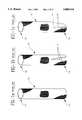
- FIGS. 1a, 1b and 1cdepict perspective views of a graft constructed in accordance with the prior art.
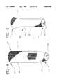
- FIGS. 2, 3, 4, 5, 6 and 7depict perspective views of shaped grafts constructed in accordance with various embodiments of the present invention.
- FIG. 8is a perspective view of a graft of the present invention having a first diameter tapering to a second diameter shown in a flat, radially compressed form after weaving but prior to heat setting.
- FIG. 9is a cross-sectional view of the graft shown in FIG. 8.
- FIG. 10is a cross-sectional view of the graft of FIG. 8 after heat setting.
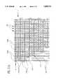
- FIGS. 11a and 11bare perspective views of weave patterns in accordance with the present invention.
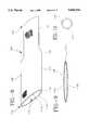
- FIG. 12is a perspective view of grafts being continuously flat-woven in accordance with the present invention, showing warp yarns gradually disengaged from the weave during weaving of one of the graft sections.
- FIG. 13shows a photomicrograph of the internal woven portion of a crotch section of a bifurcated graft of the prior art at a magnification of 10 ⁇ .
- FIG. 14shows a photomicrograph of the internal portion of a crotch section of a bifurcated graft made in accordance with the present invention at a magnification of 10 ⁇ .
- FIGS. 15, 16 and 17depict perspective views of bifurcated grafts constructed in accordance with alternative embodiments of the present invention.
- FIG. 18depicts a perspective view of a trifurcated graft constructed in accordance with an alternative embodiment of the present invention.
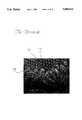
- FIG. 19shows a scanning electron micrograph of the internal portion of a crotch section of a bifurcated graft of the prior art at a magnification of 30 ⁇ .
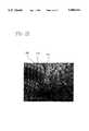
- FIG. 20shows a scanning electron micrograph of the internal portion of the crotch section of a bifurcated graft made in accordance with the present invention at a magnification of 45 ⁇ .
- FIG. 21is a perspective view of a bifurcated graft of the present invention shown in a flat, radially compressed form after weaving, but prior to heat-setting.
- FIG. 22is a cross-sectional view of the graft shown in FIG. 21.
- FIG. 23is a cross-sectional view of the graft of FIG. 21 after heat setting.
- FIG. 24is a perspective view of bifurcated grafts being continuously seamlessly flat-woven in accordance with the present invention, showing warp yarns gradually disengaged from the weave during weaving of the iliac sections.
- FIG. 25is a perspective view of bifurcated grafts being continuously seamlessly flat-woven in accordance with the present invention, showing warp yarns gradually disengaged from the weave during weaving of the aortic section.
- FIG. 26is a perspective view of the bifurcated graft of FIG. 17 used in connection with the tapered graft of FIG. 5, with an internal stent shown at one portion of the graft.
- FIG. 27is a perspective view of the bifurcated graft of FIG. 17 including an internal stent extending therethrough.
- tubular woven textile productssuch as vascular grafts can be seamlessly woven into a variety of shapes and sizes, without the need for any post-weaving fabrication techniques such as cutting, sewing, suturing and the like.
- a split graftconsists of a tubular graft section of a certain diameter, which splits at a crotch area into a plurality of tubular graft sections or members of a different diameter than the first graft section.
- a bifurcated graftas depicted in FIG. 15, includes an aortic woven portion 620 with a crotch 627, and splits into first and second iliac woven portions 630a and 630b.
- split graftsare designated as having a first graft section referred to as an aortic woven portion and second graft sections referred to as iliac woven portions or iliac leg sections, since in preferred embodiments, such split grafts, i.e. bifurcated grafts, are meant for implantation within the aorta at the branch of the iliac arteries, for instance, for use in repairing an aortic aneurism.
- the present inventorsdiscovered that it is possible to disengage a warp yam from the weave pattern for that portion of the weaving process required to weave the iliac leg portions without deleterious effects.
- the number of warp yarnsgenerally remained constant throughout the weaving pattern, due to the inefficiencies and impracticability of disengaging a warp yarn for only a portion of the weaving pattern.
- the present inventionutilizes specially designed software and a customized electronic tubular weaving machine for disengaging a warp yam for a portion or portions of the weaving pattern.
- FIG. 1aa seamless tubular woven graft 10' is depicted, having a first end 12' and a second end 14', with an internal diameter extending through the tubular graft.
- FIG. 1aa seamless tubular woven graft 10' is depicted, having a first end 12' and a second end 14', with an internal diameter extending through the tubular graft.
- tubular-woven graftcould be tapered during the weaving process, producing a seamless tubular-woven graft having a tapered configuration, as well as a variety of other tapers, flares, and shapes as shown in FIGS. 2 through 7.
- a typical seamless tubular-woven textile graft 10 in accordance with the present inventionis shown generally as a tapered graft in a generally frustoconical shape.
- Graft 10is a textile product formed of a woven synthetic fabric.
- Graft 10is depicted in one embodiment in FIG. 2 which includes a generally tubular body 17 having a first end 12 and an opposed second end 14, defining therebetween an inner lumen 18 which permits passage of blood once graft 10 is implanted in the body.
- Graft 10includes continuous transitional woven portion 25 extending between first end 12 and second end 14, and extending along the entire length of graft 10.
- first end 12has a first tubular inner diameter and second end 14 having a second tubular inner diameter which is different than the inner diameter of first end 12.
- first end 12may have an inner diameter of 12 millimeters and second end 14 may have an inner diameter of 10 millimeters, with transitional woven portion 25 forming a gradual taper having successive changes in diameter throughout such that graft 10 gradually tapers from the 12 millimeter inner diameter of first end 12 to the 10 millimeter inner diameter of second end 14 along the length of transitional woven portion 25.
- the gradual tapering of transitional woven portion 25is accomplished by gradually disengaging and/or engaging a selected number of warp yarns from the weaving pattern during weaving of the graft, as will be discussed in more detail herein.
- FIGS. 3, 4, 5, 6 and 7show various shapes of grafts that can be formed according to the present invention.
- FIG. 3shows a variation of the configuration of FIG. 2, with graft 100 in the form of a step-tapered graft having a tubular body 117 with a first end 112 and an opposed second end 114 defining an inner lumen 118 therebetween.
- graft 100includes first woven portion 120 which defines a portion of tubular wall 117 having a continuous first inner diameter and second woven portion 130 which defines a portion of tubular wall 117 having a continuous second inner diameter which is different than the inner diameter of first woven portion 120.
- graft 100includes a constant diameter extending through first woven portion 120 and a constant diameter which is different than the inner diameter of first woven portion 120 which extends through second woven portion 130, and gradually tapers from the inner diameter of first woven portion 120 to the inner diameter of second woven portion 130 through the length of transitional woven portion 125.
- FIG. 4shows a further variation on the step-tapered configuration of FIG. 3, with graft 200 having a tubular body 217 with a first end 212 and an opposed second end 214 defining an inner lumen 218 therebetween.
- graft 200includes a first woven portion 220 and a transitional woven portion 225, with the first woven portion 220 defining first end 212 and including a continuous inner diameter along the length thereof, and the transitional woven portion 225 defining second end 214 and including a gradual taper such that graft 200 gradually tapers from the inner diameter of first woven portion 220 to a second diameter at second end 214 which is different than the inner diameter of first woven portion 220. It is contemplated that such gradual tapering can be either an inward taper or an outward taper (flared).
- FIG. 5shows a further variation on the configuration of graft 10 of FIG. 2, with graft 300 having a tubular body 317 with a first end 312 and an opposed second end 314 defining an inner lumen 318 therebetween.
- graft 300includes a transitional woven portion 325 and a second woven portion 330, with the transitional woven portion 325 defining first end 312 and the second woven portion 330 including a continuous inner diameter along the length thereof, and defining second end 314.
- transitional woven portion 325includes a gradual taper such that graft 300 gradually tapers outwardly from the inner diameter of first end 312 to a second diameter at second end 314 which is different than the inner diameter of first end 312.
- FIGS. 6 and 7show further shapes which can be formed according to the present invention.
- FIG. 6depicts a sinusoidal shaped graft 400 having a tubular body 417 with a first end 412 and an opposed second end 414 defining an inner lumen 418 therebetween.
- graft 400includes a continuous first woven portion 420, with the first woven portion 420 defining both first and second ends 412 and 414.
- First woven portion 420has a continuous inner diameter along the length thereof, such that first end 412 and second end 414 have the same inner diameter.
- Graft 400is shaped along its length in an "S" configuration, with tubular body 417 gradually changing direction as warp yarns on one edge of graft 400 during the weaving process are engaged or disengaged while the same portion of tubular body 417 on the other edge of graft 400 equally changes in the same direction as warp yarns are engaged or disengaged at this edge.
- the corresponding warp yarns at the opposite edge on the same pickare engaged.
- warp yarns at a given pick on one edgemay be engaging as corresponding warp yarns at the other edge on the same pick may be disengaging.
- the warp yarns at each of the edges of the tubular graftmust simultaneously change by additionally adding or engaging an equal number of warp yarns on one edge as the other edge loses or disengages warps.
- the total number of warp yarns within the tubular wallremains constant during the weaving process.
- FIG. 7depicts a variation of the sinusoidal shaped graft 400 shown in FIG. 6.
- Graft 500 in FIG. 7includes a tubular body 517 with a first end 512 and an opposed second end 514 defining an inner lumen 518 therebetween.
- graft 500includes first woven portion 520 having a first inner diameter and second woven portion 530 having a second inner diameter which is different than the inner diameter of first woven portion 520.
- Graft 500further includes transitional woven portion 525 adjacent first and second woven portions 520 and 530.
- first woven portion 520may include a woven graft section having an inner diameter of 12 millimeters and second woven portion 530 may include a woven graft section having an inner diameter of 10 millimeters, with transitional woven portion 525 forming a gradual taper such that graft 500 gradually tapers from the 12 millimeter inner diameter of first woven portion 520 to the 10 millimeter inner diameter of second woven portion 530 along the length of transitional woven portion 525.
- Graft 500is shaped along its length in an "S" configuration similar to the manner in FIG. 6, with tubular body 517 gradually tapering in on one side of graft 500 during the weaving process while the same portion of tubular body 517 on the other side of graft 500 tapers outwardly.
- any seamless tubular flat-woven graft incorporating a gradual transitional continuously woven portionis contemplated by the present invention.
- the gradual tapering of the transitional woven portionis accomplished in each of the inventive embodiments by gradually disengaging and/or engaging a selected number of warp yarns from the weaving pattern during weaving of the graft, as will be discussed in more detail herein.
- any type of textile productcan be used as the warp yarns and fill yarns of the present invention.
- synthetic materialssuch as thermoplastic polymers.
- Thermoplastic yarns suitable for use in the present inventioninclude, but are not limited to, polyesters, polypropylenes, polyethylenes, polyurethanes and polytetrafluoroethylenes.
- the yarnsmay be of the monofilament, multifilament, or spun type.
- the yarns used in forming the woven grafts of the present inventionmay be flat, twisted or textured, and may have high, low or moderate shrinkage properties. Additionally, the yam type and yam denier can be selected to meet specific properties desired for the prosthesis, such as porosity, flexibility and compliance.
- the yarn denierrepresents the linear density of the yam (number of grams mass divided by 9,000 meters of length). Thus, a yam with a small denier would correspond to a very fine yarn whereas a yam with a larger denier, e.g., 1000, would correspond to a heavy yarn.
- the yarns used with the present inventionmay have a denier from about 20 to about 1000, preferably from about 40 to about 300.
- the warp and fill yarnsare polyester, and most preferably the warp and fill yarns are one ply, 50 denier, 48 filament flat polyester.
- the graft of the present inventioncan be woven using any known weave pattern in the art, including, simple weaves, basket weaves, twill weaves, velour weaves and the like, and is preferably woven using a flat plain tubular weave pattern, most preferably with about 170-190 warp yarns (ends) per inch per layer and about 86-90 fill yarns (picks) per inch per layer.
- the wall thickness of the graftmay be any conventional useful thickness, but is preferably no greater than about 0.16 mm, with the most preferable wall thickness being from about 0.07 mm to about 0.14 mm. These thicknesses facilitate the folding of the graft into an appropriate delivery system.
- the seamless (i.e., sutureless) feature of the present inventionfurther facilitates packing and folding of the graft into the delivery system.
- transition from one diameter to another diameteris accomplished by gradually engaging and/or disengaging selected warp yarns from the weave pattern.
- transitioncan be effectively accomplished by engaging or disengaging a maximum of three warp yarns per four successive machine picks for a given weave pattern on each edge of the graft.
- Such disengaging or engaging of warp yarnscan be accomplished in any combination of numbers. For example, up to three warp yarns can be disengaged or engaged at any of the four successive machine picks, as long as the total number of warp yarns engaged and/or disengaged does not exceed a maximum of three warp yarns per four machine picks on each edge of the tubular flat-woven product.
- An edgeis defined as an outer limit of the graft width as taken along the longitudinal axis as the graft is flat-woven on the loom.
- FIG. 8shows such edges at 117c.
- two machine picksrepresents one filling pick of tubular fabric, i.e., one tubular fill yarn.
- four machine picksrepresents two tubular fill yarns.
- the tubular-woven graft of the present inventionis constructed of polyester which is capable of shrinking during a heat set process.
- such graftsare typically flat-woven in a tubular form. Due to the nature of the flat-weaving process, the tubular graft is generally flat in shape after weaving, as depicted in FIG. 8, which shows a graft 100 in one embodiment of the present invention as flat-woven in a tubular step-tapered form as shown in FIG. 3.
- FIG.9shows a flat-woven tubular graft subsequent to weaving is generally eliptical.
- Such graftswhen constructed of heat-settable polyester yam, can be heat set on a mandrel to form a generally circular shape, as depicted in FIG. 10.
- Such a heat setting processis accomplished by first flat-weaving the graft in a tubular form out of a material capable of shrinking during a heat setting process. After the graft is woven, the graft is placed on a mandrel, and heated in an oven at a temperature and time capable of causing the yarns of the graft to heat set to the shape and diameter of the mandrel.
- polyester yarnsare used as the warp and fill yarns, and the heat setting is accomplished at time and temperatures appropriate for the material.
- heat settingcan be accomplished at about 190°-200° C. for a period of about 14-16 minutes. Other methods of heat setting known in the art may be employed.
- the graftcan be formed into a shape desired for implantation, having a generally circular inner lumen.
- tubular wall 117is comprised of top tubular body portion 117a and bottom tubular body portion 117b, which connect at tubular body edges 117c. While reference has been made to a heat setting process for forming graft 100 into a generally cylindrical shape as shown in FIG. 10, graft 100 can be provided as a finished product in the generally flat shape shown in FIG. 9, or can be made cylindrical in shape by any known methods. Further, crimping of the graft 100 along the length of tubular wall 117 to provide structural integrity is contemplated.
- FIG. 11ashows a conventional plain tubular weave pattern known in the art.
- Warp yarns 160are further shown as 160a indicating they are in the top layer of the weave and 160b indicating their presence in the bottom layer of the weave.
- Top warp yarns 160a and bottom warp yarns 160brun in a lengthwise direction in the graft and define the width of the graft.
- Fill yarns 170are further shown as top fill yarns 170a and bottom fill yarns 170b. These fill yarns are woven with the top and bottom warp yarns 160a and 160b as shown in FIG. 11a in a manner known in the art.
- a filling yam shuttlepasses across warp yarns 160 while selected warp yarns 160 are lifted according to a specific weave pattern.
- weave patternscan be programmed using software into the machine.
- the shuttleIn a typical plain tubular weave as depicted in FIG. 11a, the shuttle first weaves top fill yarn 170a by passing across warp yarns 160 while certain warp yarns 160 are lifted.
- the bottom warp yarns 160bare not lifted to prevent top fill yarns 170a from interweaving with bottom warp yarns 160b.
- top warp yarns 160aare always lifted such that bottom fill yarns 170b are not interwoven with top warp yarns 160a.
- the plain tubular weave pattern as just describedcan be used to form straight portions of the inventive grafts which have a constant diameter. This pattern is then modified by gradually engaging or disengaging warp yarns to create tapers and/or shapes.
- the plain weave pattern shown in FIG. 11a and described aboveis formed by continuously passing top and bottom fill yarns 170a and 170b back and forth across warp yarns 160 to form first woven portion 120 of graft 100 shown in FIG. 12.
- FIG. 11bshows a plain tubular weave pattern having a gradual disengaging of warp yarns.
- warp yarns 160'have been disengaged from the pattern and are no longer interwoven beginning at the fill yam 170'.
- the next set of picksshows an additional warp yarn being disengaged.
- the patternis within the maximum disengagement of three warp yarns per four machine picks.
- the disengaging of the warp yarnsis accomplished by dropping the desired warp yarns from the end of the tubular flat-woven graft during the weaving process, such that the fill yarns are not interwoven across the warp yarns for that section of the pattern. Such dropping of warp yarns in a gradual manner forms the transitional portion of the graft. In continuous flat-weaving processes, the warp yarns are then re-engaged during the weave pattern once the transitional section has been completed.
- the weave patternmay be repeated creating the next graft to be woven in a continuous process.
- FIG. 12shows a plurality of grafts 100 being woven in a continuous flat-weaving process, in accordance with the present invention.
- First woven portion 120is of one inner diameter, for instance 24 millimeters, while second woven portion 130 is of another inner diameter different than that of first woven portion 120, for instance 18 millimeters.
- first woven portion 120requires more warp yarns 160 for weaving than does second woven portion 130.
- the warp yarnsare gradually disengaged from the weave, as depicted by disengaged warp yarns 160'.
- the grafts of the present inventionare preferably fabricated using a continuous flat-weaving process, disengaged warp yarns 160' must be re-engaged into the weave pattern after completion of the second woven portion in order to begin weaving the first woven portion of the subsequent graft to be produced.
- a continuous flat-weaving processa plurality of grafts 100 can be woven in a continuous manner, and can be cut apart along line C after fabrication. Furthermore, disengaged warp yarns 160' are removed subsequent to weaving.
- the bifurcated graftwould have to be first woven in a conventional manner, followed by cutting and suturing of the iliac to achieve the desired diameter.
- grafts produced in such a mannerresulted in many drawbacks. For instance, the suture seam added to the wall thickness of the graft and added a discontinuity to the internal wall surface of the graft.
- FIG. 13shows a photomicrograph of an enlarged view of the internal portion of a prior art bifurcated graft woven of warp yarns 161 and fill yarns 171 at the crotch area 627' of the graft, where the two iliac leg portions branch off from the aortic portion. Needle holes 140 are present in the wall of the graft, representing holes through the graft wall which were made by a needle during suturing of the iliac leg portions to the aortic portion.
- split graftssuch as bifurcated grafts can be flat-woven in a tubular form with varying diameters in the iliac portions and the aortic portion, without the need for such post-fabrication suturing.
- Thisis accomplished by a gradual transition in the number of warp yarns in the weave of the graft, as accomplished in the tapered grafts discussed above.
- Such gradual transitionis accomplished by gradually engaging or disengaging warp yarns during the fabrication of the graft at the transition from the aortic graft portion to the iliac leg portions of the graft.
- a bifurcated graft produced in this manneris shown in an enlarged view at FIG. 14.
- FIG. 14A bifurcated graft produced in this manner is shown in an enlarged view at FIG. 14.
- FIG. 14shows a bifurcated graft having first and second iliac woven portions 630a and 630b.
- the needle holes 140which were created from the suturing needle required for attachment of the iliac legs in the prior art grafts are not present in the graft produced in accordance with the present invention.
- a typical tubular woven bifurcated graft 600includes a generally tubular body 617 having a first end 612 and opposed second ends 614a and 614b, defining therebetween an inner lumen 618 which permits passage of blood once bifurcated graft 600 is implanted in a blood vessel.
- Bifurcated graft 600includes aortic woven portion 620 having a first inner diameter, and further includes first and second iliac woven tubular wall portions 630a and 630b each having an inner diameter which is different than the inner diameter of aortic woven portion 620.
- the inner diameters of first and second iliac woven portions 630a and 630bcan be the same, as depicted in FIG.
- Bifurcated graft 600further includes bifurcated transitional woven portion 625 contiguous with aortic woven portion 620 and first and second iliac woven portions 630a and 630b at crotch 627 forming a bifurcated arch.
- Bifurcated transitional woven portion 625forms a gradual taper such that bifurcated graft 600 gradually tapers from the inner diameter of aortic woven portion 620 to the inner diameters of first and second iliac woven portions 630a and 630b along the length of bifurcated transitional woven portion 625.
- the gradual tapering of bifurcated transitional woven portion 625is accomplished by gradually disengaging and/or engaging a selected number of warp yarns from the weaving pattern during weaving of the graft, as accomplished in the preferred embodiment discussed above.
- FIG. 18depicts a trifurcated graft 900 in accordance with an alternative embodiment of the present invention.
- Trifurcated graft 900is of the same general configuration as bifurcated graft 600 shown in FIG. 17, including a generally tubular body 917 having first end 912, second ends 914a, 914b and 914c with first woven portion 920, transitional woven portion 925, first and second iliac woven portions 930a and 930b, and further includes an additional iliac leg as iliac woven portion 930c.
- trifurcated graft 900also includes crotches 927a, 927b and 927c (not shown), extending between transitional woven portion 925 and each of iliac woven portions 930a, 930b and 930c.
- FIG. 19is a scanning electron micrograph of a prior art bifurcated graft showing the crotch area in an enlarged view. Warp yarns 161 and fill yarns 171 are seen generally in the micrograph. Crotch sutures 150 are shown, which undesirably create an added area of wall thickness in the graft.
- voids in the crotch area of a split graftcan be avoided by gradually transferring the warp yarns during the weaving process from one woven section to another woven section contiguous thereto, thereby avoiding the necessity for post-fabrication suturing of voids.
- a closed weaveis established in crotch 627 of a bifurcated graft 600, by gradually transferring the warp yarns during the weaving process from one woven section to another woven section contiguous therewith.
- the warp yarns 160 which are being interwoven by the fill yarns 170are gradually transferred from the aortic woven section 620 and the transitional woven section 625 to each of the iliac woven portions 630a and 630b.
- two separate filling yarn shuttlesare required for weaving of the two distinct iliac woven portions 630a and 630b.
- the shuttle designated for weaving of iliac woven portion 630aselectively and gradually engages warp yarns designated for weaving of iliac woven portion 630b.
- the shuttle designated for weaving iliac woven portion 630bselectively and gradually engages warp yarns designated for weaving of iliac woven portion 630a.
- the crotch 627is woven using a simultaneous tapering effect at the interface between the aortic woven portion 620 and iliac woven portions 630a and 630b. As such, a smooth contiguous surface transition is obtained.
- the aortic sectionachieved the 26 millimeter diameter
- the iliac leg portionsshrunk to a smaller diameter than 13 millimeters, making the graft difficult to remove from the mandrel.
- the graftwas not a true 26 ⁇ 13 ⁇ 13 set of diameters.
- the inventionemploys customized, programmable electronic jacquard weaving machines to gradually engage and/or disengage selected warp yarns from the weaving pattern during weaving of a flat-woven tubular product.
- the present inventorhas discovered that the number of warp yarns required for each of the tubular segments having different diameters can be pre-determined to account for the variation in heat shrinkage from one diameter to the next.
- a method of forming a flat-woven synthetic tubular implantable prosthesis having a precise pre-determined internal diameteris provided. In the method, a desired weaving pattern is first selected for constructing the prosthesis.
- the weaving patternis selected from the group consisting of a simple weave (plain weave), a basket weave, a twill weave, and velour weaves.
- a desired yarn size and yarn diameteris then provided for the weaving pattern.
- the density at which the yarn is to be woven in the weaveis then chosen, represented by a specific number of warp yarns per unit diameter.
- a selected number of warp yarnsis provided for weaving a suitable tubing edge.
- the desired internal diameter of the tubular prosthesisis then selected. Based upon knowing these parameters, the total number of warp yarns required to weave the tubular prosthesis with such a desired internal diameter can be calculated using the following formula:
- Nrepresents the total number of warp yarns required
- Srepresents the number of edge warp yarns required to weave a suitable tubing edge
- Drepresents the desired internal diameter
- ⁇represents the number of warp yarns per unit of diameter.
- bifurcated graft 600 of FIG. 21is depicted in a generally flat tubular shape subsequent to weaving, with top tubular wall portion 617a and bottom tubular wall portion 617b connecting at tubular edges 617c in a similar means as graft 100, previously discussed with relation to FIGS. 8-10.
- FIGS. 24 and 25show a plurality of bifurcated grafts 600 being woven in a continuous flat-weaving process, in accordance with one embodiment of the present invention.
- Bifurcated grafts 600as shown in FIGS. 24 and 25, are woven in a similar manner as grafts 100, depicted in FIG. 12.
- bifurcated graft 600includes aortic woven portion 620 and first and second iliac woven portions 630a and 630b, with aortic woven portion 620 requiring more warp yarns for weaving than the iliac woven portions 630a and 630b.
- iliac woven portions 630a and 630brequire more warp yarns for weaving than aortic woven portion 620, and thus the disengaged warp yarns 660' are disengaged during weaving of the aortic woven section.
- FIG. 26shows a bifurcated graft in accordance with one embodiment of the present invention, including a stent 50 affixed thereto at one portion of bifurcated graft 600.
- FIG. 27shows a bifurcated graft in accordance with an alternative embodiment of the present invention, having stent 50 substantially along the entire length of tubular wall 617, positioned within the inner lumen of bifurcated graft.
- a stent 50is well known in the art, and can be constructed in any desired shape and of any material known in the art, for example, a shaped memory alloy, as disclosed in International Application No. PCT/US95/01466, incorporated herein by reference. It is contemplated by the present invention that stent 50, as well as other stent types, can be used in such a manner with any of the tubular woven grafts of the present invention.
- a stepped graft(no taper) was flat-woven on an electronic jacquard loom in a tubular configuration to produce a 12 millimeter inner diameter section of the graft and a 10 millimeter inner diameter portion of the graft.
- the number of warp yarns required for weaving the 12 millimeter inner diameter portion of the graftwas calculated using the above-mentioned method for pre-determining the number of warp yarns required to achieve the true desired diameters upon heat shrinking as follows:
- the number of warp yarns required for weaving the 10 millimeter inner diameter portion of the graftwas similarly calculated as follows:
- the 12 millimeter inner diameter portion of the graftwas first flat-woven to a desired length. During the flat-weaving process, 46 warp yarns were disengaged from the weaving pattern all at once, i.e., at a single machine pick, in order to produce the 10 millimeter inner diameter portion of the graft.
- the graft thus producedincluded a 12 millimeter inner diameter portion and a 10 millimeter inner diameter portion. The transition between the two portions, however, included large holes between the weave sections of the graft which were visible to the naked eye.
- a graft having a 12 millimeter inner diameter portion and a 10 millimeter inner diameter portionwas flat-woven in a manner similar to that of Example 1. During the transition from the 12 millimeter inner diameter portion to the 10 millimeter inner diameter portion, however, all 46 warp yarns were not disengaged at once transitioning to the 10 millimeter diameter portion. Instead, 4 or more warp yarns were disengaged for every 2 machine picks.
- the graft thus producedincluded a 12 millimeter inner diameter portion and a 10 millimeter inner diameter portion. The transition between the two portions, however, also included unacceptable holes between the weave sections of the graft which were visible to the naked eye.
- a graft having a 12 millimeter inner diameter portion and a 10 millimeter inner diameter portionwas flat-woven in a manner similar to that of Example 2. During the transition from the 12 millimeter inner diameter portion to the 10 millimeter inner diameter portion, either 1 or 2 warp yarns were disengaged for every 4 machine picks, with a maximum of 3 warp yarns being disengaged for every 4 machine picks.
- the graft thus producedincluded a 12 millimeter inner diameter portion and a 10 millimeter inner diameter portion. The transition between the two portions included a gradual transition with no holes between the weave sections of the graft.
- a set of bifurcated graftswere flat-woven in a tubular configuration to produce an aortic section having a 24, 26 and 28 millimeter inner diameter and two iliac leg sections having a 12, 13 and 14 millimeter inner diameter for each leg section, respectively.
- the aortic section of the graftswere first flat-woven. When the weave reached the bifurcation portion, the previously described inventive method of gradually changing the warps was not employed.
- the number of warp yarnswere split all at once, i.e., at a given pick, with one warp yarn being disengaged as necessary for one leg of the iliac leg section in order to produce the correct weave pattern (obtain an odd warp yarn number).
- the number of warp yarns used for each graftis shown in Tables 1-3.
- the graftswere woven, they were placed on steel mandrels and heat set in an oven for a sufficient time and temperature to heat-set their shapes and size, i.e., at a temperature of 190°-200° C. for 14-16 minutes.
- the aortic section of each of the graftswas properly heat set to an inner diameter of 24, 26 and 28 millimeters.
- the iliac leg sectionswere heat set too tightly on the mandrels, making it difficult to remove the leg sections from the mandrels.
- the actual inner diameter of each of the iliac leg sectionswas less than the desired 12, 13 and 14 millimeters, respectively.
- the following exampledemonstrates the use of the inventive method of forming a bifurcated graft of a desired diameter.
- This inventionalso shows, however, that when the rate of changing (disengaging or engaging) the warp yarns is greater than 3 warp yarns per 4 machine, unacceptable voids are present in the weave.
- a set of bifurcated graftswere flat-woven in a tubular configuration in a similar manner as in Example 4, to produce an aortic section having a 24, 26 and 28 millimeter inner diameter and two iliac leg sections having a 12, 13 and 14 millimeter inner diameter for each leg section, respectively.
- the aortic section of the graftwere first flat-woven. When the flat-woven. When the weave reached the bifurcation portion, the number of wrap yarns was adjusted by disengaging warp yarns from the weave pattern at a rate of 4 warp yarns being disengaged for every 4 machine picks. The total number of warp yarns used for each graft was calculated by the formula as described herein.
- the graftswere woven, they were placed on steel mandrels and heat set in an oven at a temperature of 190°-200° C. for 14-16 minutes. After removing the grafts from the mandrels, the aortic section of each of the grafts was properly heat set to an inner diameter of 24, 26 and 28 millimeters, respectively. The iliac leg sections were also properly heat set to an inner diameter of 12, 13 and 14 millimeters, respectively. When the disengaged warp yarns were removed from the exterior portion of the aortic graft section, however, holes visible to the naked eye were present in the tubular wall of the graft at the transition between the aortic portion and the iliac leg portions.
- This exampledemonstrates the use of the inventive embodiment, i.e., using gradually disengaged warp yarns to transition from the aortic section to the iliac sections, and the use of the inventive method of calculating the number of warp yarns required for a given diameter.
- a set of bifurcated graftswere flat-woven in a tubular configuration in the same manner as in Example 5, to produce an aortic section having a 24, 26 and 28 millimeter inner diameter and two iliac leg sections having a 12, 13 and 14 millimeter inner diameter for each leg section, respectively.
- the number of warp yarnswas adjusted by disengaging warp yarns from the weave pattern at a rate of no more than 3 warp yarns being disengaged for every 4 machine picks.
- the inner diameters of the aortic section of each of the graftsmeasured 24, 26 and 28 millimeters, respectively, and diameters of the iliac leg sections measured 12, 13 and 14 millimeters, respectively.
- the precise desired inner diameterswere thus obtained using the inventive method of determining the proper number of warp yarns necessary to account for heat set shrinkage.
- no holeswere present in the tubular wall of the graft at the transition between the aortic portion and the iliac leg portions. This clearly demonstrates the necessity for the gradual change in warp yarns as claimed herein.
Landscapes
- Health & Medical Sciences (AREA)
- Engineering & Computer Science (AREA)
- Heart & Thoracic Surgery (AREA)
- Animal Behavior & Ethology (AREA)
- Oral & Maxillofacial Surgery (AREA)
- Transplantation (AREA)
- Pulmonology (AREA)
- Biomedical Technology (AREA)
- Gastroenterology & Hepatology (AREA)
- Vascular Medicine (AREA)
- Life Sciences & Earth Sciences (AREA)
- Cardiology (AREA)
- General Health & Medical Sciences (AREA)
- Public Health (AREA)
- Veterinary Medicine (AREA)
- Textile Engineering (AREA)
- Prostheses (AREA)
- Woven Fabrics (AREA)
- Materials For Medical Uses (AREA)
Abstract
Description
N=S+(D×ρ)
N=S+(D×ρ)
N=S+(D×ρ)
N=29+(12×23)
N=305
N=29+(10×23)
N=259
TABLE 1 ______________________________________ NUMBER OF NUMBER OF WARP YARNS USED WARP YARNS USED FOR 24 mm FOR EACH 12 mm AORTIC SECTION ILIAC SECTION ______________________________________ Graft 1A 583 291 Graft 1B 587 293 Graft 1C 591 295 Graft 1D 595 297 ______________________________________
TABLE 2 ______________________________________ NUMBER OF NUMBER OF WARP YARNS USED WARP YARNS USED FOR 26 mm FOR EACH 13 mm AORTIC SECTION ILIAC SECTION ______________________________________ Graft 2A 657 313 Graft 2B 631 315 Graft 2C 635 317 Graft 2D 639 319 ______________________________________
TABLE 3 ______________________________________ NUMBER OF NUMBER OF WARP YARNS USED WARP YARNS USED FOR 28 mm FOR EACH 14 mm AORTIC SECTION ILIAC SECTION ______________________________________ Graft 3A 675 337 Graft 3B 679 339 Graft 3C 683 341 Graft 3D 687 343 ______________________________________
N=S+(D×ρ)
TABLE 4 ______________________________________ NUMBER OF WARP NUMBER OF WARP YARNS USED FOR YARNS USED FOR 24 mm AORTIC SECTION EACH 12 mm ILIAC SECTION ______________________________________ Graft 4 581 305 ______________________________________
TABLE 5 ______________________________________ NUMBER OF WARP NUMBER OF WARP YARNS USED FOR YARNS USED FOR 26 mm AORTIC SECTION EACH 13 mm ILIAC SECTION ______________________________________ Graft 5 627 327 ______________________________________
TABLE 6 ______________________________________ NUMBER OF WARP NUMBER OF WARP YARNS USED FOR YARNS USED FOR 28 mm AORTIC SECTION EACH 14 mm ILIAC SECTION ______________________________________ Graft 6 673 351 ______________________________________
Claims (33)
Priority Applications (15)
| Application Number | Priority Date | Filing Date | Title |
|---|---|---|---|
| US08/653,028US5800514A (en) | 1996-05-24 | 1996-05-24 | Shaped woven tubular soft-tissue prostheses and methods of manufacturing |
| DE69728268TDE69728268T2 (en) | 1996-05-24 | 1997-05-20 | SHAPED, WOVEN TUBE PROTECTION FOR SOFT TISSUE AND MANUFACTURING METHOD |
| EP04075086AEP1433440A2 (en) | 1996-05-24 | 1997-05-20 | Shaped woven tubular soft-tissue prostheses and methods of manufacturing |
| JP54268697AJP3442402B2 (en) | 1996-05-24 | 1997-05-20 | Artificial attachment for molded tubular hard woven fabric and method of manufacturing |
| AU32087/97AAU729443B2 (en) | 1996-05-24 | 1997-05-20 | Shaped woven tubular soft-tissue prostheses and methods of manufacturing |
| CA002256324ACA2256324C (en) | 1996-05-24 | 1997-05-20 | Shaped woven tubular soft-tissue prostheses and methods of manufacturing |
| CA002422915ACA2422915C (en) | 1996-05-24 | 1997-05-20 | Shaped woven tubular soft-tissue prostheses and methods of manufacturing |
| EP97927686AEP0910310B1 (en) | 1996-05-24 | 1997-05-20 | Shaped woven tubular soft-tissue prostheses and methods of manufacturing |
| PCT/US1997/008602WO1997043983A1 (en) | 1996-05-24 | 1997-05-20 | Shaped woven tubular soft-tissue prostheses and methods of manufacturing |
| US08/976,544US5904714A (en) | 1996-05-24 | 1997-11-24 | Shaped woven tubular soft-tissue prostheses and methods of manufacturing |
| US09/247,149US6136022A (en) | 1996-05-24 | 1999-02-09 | Shaped woven tubular soft-tissue prostheses and methods of manufacturing the same |
| US09/611,861US6596023B1 (en) | 1996-05-24 | 2000-07-07 | Shaped woven tubular soft-tissue prostheses and method of manufacturing the same |
| US10/319,175US7550006B2 (en) | 1996-05-24 | 2002-12-12 | Shaped woven tubular soft-tissue prostheses and method of manufacturing the same |
| US10/317,757US6821294B2 (en) | 1996-05-24 | 2002-12-12 | Shaped woven tubular soft-tissue prostheses and method of manufacturing the same |
| US10/437,711US6840958B2 (en) | 1996-05-24 | 2003-05-14 | Shaped woven tubular soft-tissue prostheses and method of manufacturing the same |
Applications Claiming Priority (1)
| Application Number | Priority Date | Filing Date | Title |
|---|---|---|---|
| US08/653,028US5800514A (en) | 1996-05-24 | 1996-05-24 | Shaped woven tubular soft-tissue prostheses and methods of manufacturing |
Related Child Applications (1)
| Application Number | Title | Priority Date | Filing Date |
|---|---|---|---|
| US08/976,544DivisionUS5904714A (en) | 1996-05-24 | 1997-11-24 | Shaped woven tubular soft-tissue prostheses and methods of manufacturing |
Publications (1)
| Publication Number | Publication Date |
|---|---|
| US5800514Atrue US5800514A (en) | 1998-09-01 |
Family
ID=24619200
Family Applications (7)
| Application Number | Title | Priority Date | Filing Date |
|---|---|---|---|
| US08/653,028Expired - LifetimeUS5800514A (en) | 1996-05-24 | 1996-05-24 | Shaped woven tubular soft-tissue prostheses and methods of manufacturing |
| US08/976,544Expired - LifetimeUS5904714A (en) | 1996-05-24 | 1997-11-24 | Shaped woven tubular soft-tissue prostheses and methods of manufacturing |
| US09/247,149Expired - LifetimeUS6136022A (en) | 1996-05-24 | 1999-02-09 | Shaped woven tubular soft-tissue prostheses and methods of manufacturing the same |
| US09/611,861Expired - Fee RelatedUS6596023B1 (en) | 1996-05-24 | 2000-07-07 | Shaped woven tubular soft-tissue prostheses and method of manufacturing the same |
| US10/317,757Expired - Fee RelatedUS6821294B2 (en) | 1996-05-24 | 2002-12-12 | Shaped woven tubular soft-tissue prostheses and method of manufacturing the same |
| US10/319,175Expired - Fee RelatedUS7550006B2 (en) | 1996-05-24 | 2002-12-12 | Shaped woven tubular soft-tissue prostheses and method of manufacturing the same |
| US10/437,711Expired - Fee RelatedUS6840958B2 (en) | 1996-05-24 | 2003-05-14 | Shaped woven tubular soft-tissue prostheses and method of manufacturing the same |
Family Applications After (6)
| Application Number | Title | Priority Date | Filing Date |
|---|---|---|---|
| US08/976,544Expired - LifetimeUS5904714A (en) | 1996-05-24 | 1997-11-24 | Shaped woven tubular soft-tissue prostheses and methods of manufacturing |
| US09/247,149Expired - LifetimeUS6136022A (en) | 1996-05-24 | 1999-02-09 | Shaped woven tubular soft-tissue prostheses and methods of manufacturing the same |
| US09/611,861Expired - Fee RelatedUS6596023B1 (en) | 1996-05-24 | 2000-07-07 | Shaped woven tubular soft-tissue prostheses and method of manufacturing the same |
| US10/317,757Expired - Fee RelatedUS6821294B2 (en) | 1996-05-24 | 2002-12-12 | Shaped woven tubular soft-tissue prostheses and method of manufacturing the same |
| US10/319,175Expired - Fee RelatedUS7550006B2 (en) | 1996-05-24 | 2002-12-12 | Shaped woven tubular soft-tissue prostheses and method of manufacturing the same |
| US10/437,711Expired - Fee RelatedUS6840958B2 (en) | 1996-05-24 | 2003-05-14 | Shaped woven tubular soft-tissue prostheses and method of manufacturing the same |
Country Status (6)
| Country | Link |
|---|---|
| US (7) | US5800514A (en) |
| EP (2) | EP0910310B1 (en) |
| JP (1) | JP3442402B2 (en) |
| CA (1) | CA2256324C (en) |
| DE (1) | DE69728268T2 (en) |
| WO (1) | WO1997043983A1 (en) |
Cited By (126)
| Publication number | Priority date | Publication date | Assignee | Title |
|---|---|---|---|---|
| US5938697A (en)* | 1998-03-04 | 1999-08-17 | Scimed Life Systems, Inc. | Stent having variable properties |
| WO1999040875A1 (en)* | 1998-02-12 | 1999-08-19 | Prodesco, Inc. | Tapered tubular prosthesis and method of making |
| US6146414A (en)* | 1997-12-19 | 2000-11-14 | Gelman; Martin L. | Medical graft and construction of the same |
| US6149682A (en)* | 1997-01-16 | 2000-11-21 | Medicorp R & D Benelux S.A. | Luminal endoprosthesis for ramification |
| US6238432B1 (en)* | 1998-08-25 | 2001-05-29 | Juan Carlos Parodi | Stent graft device for treating abdominal aortic aneurysms |
| WO2002039928A2 (en) | 2000-11-15 | 2002-05-23 | Mcmurray Fabrics, Inc. | Soft-tissue tubular prostheses with seamed transitions |
| US20020077634A1 (en)* | 1995-10-30 | 2002-06-20 | Leonhardt Howard J. | Method for engrafting a blood vessel |
| WO2002035989A3 (en)* | 2000-10-30 | 2002-10-10 | Prodesco | Woven tubular graft with regions of varying flexibility |
| US6478817B2 (en)* | 1997-09-04 | 2002-11-12 | Meadox Medicals, Inc. | Aortic arch prosthetic graft |
| US20030078650A1 (en)* | 1996-05-24 | 2003-04-24 | Meadox Medicals, Inc. | Shaped woven tubular soft-tissue prostheses and method of manufacturing the same |
| US20030114912A1 (en)* | 2000-05-30 | 2003-06-19 | Jacques Sequin | Endoprosthesis deployment system for treating vascular bifurcations |
| US20030181971A1 (en)* | 2002-03-20 | 2003-09-25 | Terumo Kabushiki Kaisha | Woven tubing for stent type blood vascular prosthesis and stent type blood vascular prosthesis using the tubing |
| US20030216803A1 (en)* | 2003-05-28 | 2003-11-20 | Ledergerber Walter J. | Textured and drug eluting stent-grafts |
| US20040006381A1 (en)* | 2000-05-30 | 2004-01-08 | Jacques Sequin | Noncylindrical drug eluting stent for treating vascular bifurcations |
| US6695833B1 (en) | 2000-09-27 | 2004-02-24 | Nellix, Inc. | Vascular stent-graft apparatus and forming method |
| US6709467B1 (en)* | 2000-02-16 | 2004-03-23 | Viktoria Kantsevitcha | Arterial prosthesis |
| US20040116999A1 (en)* | 2003-05-28 | 2004-06-17 | Ledergerber Walter J. | Textured and drug eluting coronary artery stent |
| US20040116997A1 (en)* | 2002-09-20 | 2004-06-17 | Taylor Charles S. | Stent-graft with positioning anchor |
| US6777051B1 (en)* | 2000-08-11 | 2004-08-17 | Giacoma Ezio Mazzer | Protective sheath for flexible tubes |
| US20040215309A1 (en)* | 2001-07-31 | 2004-10-28 | Anton Moritz | Covering element for veins, method for the production and use thereof in surgery |
| US20040221623A1 (en)* | 2000-02-16 | 2004-11-11 | Viktoria Kantsevitcha | Vascular prosthesis |
| NL1023389C2 (en)* | 2003-05-12 | 2004-11-15 | Hendrik Glastra | Forming 3D article used to make blood vessel protheses, by winding two sets of yarns around form with rings of yarn guides around its ends |
| EP1187560A4 (en)* | 1999-04-26 | 2004-11-17 | William J Drasler | Intravascular folded tubular endoprosthesis |
| US20040243216A1 (en)* | 2003-05-28 | 2004-12-02 | Scimed Life Systems, Inc., Maple Grove, Mn | Stent with tapered flexibility |
| US6849087B1 (en) | 1999-10-06 | 2005-02-01 | Timothy A. M. Chuter | Device and method for staged implantation of a graft for vascular repair |
| US20050119729A1 (en)* | 2002-12-06 | 2005-06-02 | G.A.M.A.-H.S. S.R.L. | Prosthesis for large blood vessels |
| WO2005087117A1 (en)* | 2004-03-11 | 2005-09-22 | pfm Produkte für die Medizin AG | Device for rechannelling a cavity, organ path or vessel |
| US20050228489A1 (en)* | 2004-04-12 | 2005-10-13 | Scimed Life Systems, Inc. | Ultrasonic crimping of a varied diameter vascular graft |
| US20050228487A1 (en)* | 2004-04-12 | 2005-10-13 | Scimed Life Systems, Inc. | Tri-petaled aortic root vascular graft |
| US20050228488A1 (en)* | 2004-04-12 | 2005-10-13 | Scimed Life Systems, Inc. | Varied diameter vascular graft |
| US20050276914A1 (en)* | 2004-06-15 | 2005-12-15 | Liu Ming-Dah | Method for manufacturing light guide plate mold cores |
| EP1666003A1 (en)* | 2004-12-02 | 2006-06-07 | Nitinol Development Corporation | Prosthesis comprising a stent with a tapered central portion |
| US7083644B1 (en) | 2000-05-24 | 2006-08-01 | Scimed Life Systems, Inc. | Implantable prostheses with improved mechanical and chemical properties |
| US7108673B1 (en)* | 2003-07-07 | 2006-09-19 | Stan Batiste | A-V dialysis graft construction |
| US20060229709A1 (en)* | 2005-03-30 | 2006-10-12 | Morris Liam G | Vascular graft |
| US20070079886A1 (en)* | 2002-04-10 | 2007-04-12 | Rongde Ge | Method for weaving curved warp yarns and a woven fabric |
| US20070282454A1 (en)* | 2006-05-30 | 2007-12-06 | Boston Scientific Scimed Inc. | Anti-obesity diverter structure |
| US20080077070A1 (en)* | 2006-08-10 | 2008-03-27 | Kopia Gregory A | Arteriovenous shunt |
| US20080097592A1 (en)* | 2005-02-14 | 2008-04-24 | Vascutek Limited | Artificial Blood Vessel |
| US20080140012A1 (en)* | 2006-07-12 | 2008-06-12 | Binford Oswald S | Hemodialysis graft |
| US20080200978A1 (en)* | 2005-05-26 | 2008-08-21 | Texas Heart Institute | Surgical System and Method For Attaching a Prosthetic Vessel to a Hollow Structure |
| US20080228028A1 (en)* | 2007-03-12 | 2008-09-18 | Cook Incorporated | Woven fabric with shape memory element strands |
| US20080300602A1 (en)* | 2007-03-02 | 2008-12-04 | Schmitt Peter J | Fabric medical device having a tapered transition and method of making |
| US7484539B1 (en)* | 2007-12-03 | 2009-02-03 | Ching Sui Industry Co., Ltd. | Shaping method and structure of woven fabric with a groove |
| US20090171443A1 (en)* | 2007-12-27 | 2009-07-02 | Cook Incorporated | Stent graft having floating yarns |
| US20090218002A1 (en)* | 2008-02-29 | 2009-09-03 | Emi Kashihara | Protective textile sleeve having high edge abrasion resistance and method of construction |
| US20090227932A1 (en)* | 2008-03-05 | 2009-09-10 | Hemosphere, Inc. | Vascular access system |
| WO2009149645A1 (en)* | 2008-06-10 | 2009-12-17 | 微创医疗器械(上海)有限公司 | A coated tuber for the bifurcated stent and the method for cutting membrane |
| US20090325443A1 (en)* | 2004-11-19 | 2009-12-31 | Donald Blackden | Fabricating symmetric and asymmetric shapes with off-axis reinforcement from symmetric preforms |
| US20100076555A1 (en)* | 2008-09-19 | 2010-03-25 | Marten Lewis H | Coated devices comprising a fiber mesh imbedded in the device walls |
| US7686846B2 (en) | 1996-06-06 | 2010-03-30 | Devax, Inc. | Bifurcation stent and method of positioning in a body lumen |
| US20100234789A1 (en)* | 2009-03-13 | 2010-09-16 | Stanley Batiste | Self adjusting venous equalizing graft |
| US20100268327A1 (en)* | 2009-04-17 | 2010-10-21 | Medtronic Vascular, Inc. | Mobile External Coupling for Branch Vessel Connection |
| US20100268319A1 (en)* | 2009-04-17 | 2010-10-21 | Medtronic Vascular, Inc. | Mobile External Coupling for Branch Vessel Connection |
| US7841369B1 (en)* | 2009-11-18 | 2010-11-30 | vParadox LLC | Weaving process for production of a full fashioned woven stretch garment with load carriage capability |
| WO2010141553A1 (en) | 2009-06-02 | 2010-12-09 | Surmodics, Inc. | SILANE-FUNCTIONALIZED HYDROPHOBIC a(1→4)GLUCOPYRANOSE POLYMERS AND POLYMERIC MATRICES FOR IMPLANTATION OR INJECTION |
| US20110009947A1 (en)* | 2009-03-13 | 2011-01-13 | Stanley Batiste | Endothelial scaffold graft and method therefor |
| US20110005632A1 (en)* | 2008-02-14 | 2011-01-13 | Massimo Bertolani | Fabric made up of at least two laps interwoven along a common stretch and method for its production |
| US20110009946A1 (en)* | 2009-03-13 | 2011-01-13 | Stanley Batiste | Self adjusting venous equalizing graft and endothelial lining therefor |
| US20110015723A1 (en)* | 2009-03-13 | 2011-01-20 | Stanley Batiste | Adjustable stenosis and method therefor |
| US20110060264A1 (en)* | 2003-10-08 | 2011-03-10 | Hemosphere Inc. | Device and method for vascular access |
| WO2011041517A1 (en) | 2009-09-30 | 2011-04-07 | Surmodics, Inc. | Hydrophobic polysaccharides with silyl ether linkages having enhanced degradation and medical articles made therefrom |
| US7942925B2 (en) | 2001-07-09 | 2011-05-17 | Surpass Medical Ltd. | Implantable intraluminal device and method of using same in treating aneurysms |
| US7951557B2 (en) | 2003-04-27 | 2011-05-31 | Protalix Ltd. | Human lysosomal proteins from plant cell culture |
| US7988720B2 (en) | 2006-09-12 | 2011-08-02 | Boston Scientific Scimed, Inc. | Longitudinally flexible expandable stent |
| CN102212931A (en)* | 2011-06-01 | 2011-10-12 | 东华大学 | Equipment and method for weaving diameter-variable tubular fabric |
| US8167925B2 (en) | 1999-03-11 | 2012-05-01 | Endologix, Inc. | Single puncture bifurcation graft deployment system |
| US8231667B2 (en) | 2002-11-08 | 2012-07-31 | Jacques Séguin | Endoprosthesis for vascular bifurcation |
| US8292951B2 (en) | 2010-04-29 | 2012-10-23 | Medtronic Vascular, Inc. | Tethered pop up branch structure stent graft and method |
| US8323328B2 (en) | 1995-12-14 | 2012-12-04 | W. L. Gore & Associates, Inc. | Kink resistant stent-graft |
| US8333800B2 (en) | 2010-04-29 | 2012-12-18 | Medtronic Vascular, Inc. | Mobile external coupling with internal sealing cuff for branch vessel connection |
| US8337546B2 (en) | 2010-04-29 | 2012-12-25 | Medtronic Vascular, Inc. | Mobile external coupling for branch vessel connection |
| US8388679B2 (en) | 2007-01-19 | 2013-03-05 | Maquet Cardiovascular Llc | Single continuous piece prosthetic tubular aortic conduit and method for manufacturing the same |
| US20130066328A1 (en)* | 2011-04-07 | 2013-03-14 | Jai Singh | General uterine manipulator and system |
| US8449597B2 (en) | 1995-03-01 | 2013-05-28 | Boston Scientific Scimed, Inc. | Longitudinally flexible expandable stent |
| US20130197536A1 (en)* | 2011-04-07 | 2013-08-01 | Jai Singh | General uterine manipulator and system |
| US20130302571A1 (en)* | 2011-01-18 | 2013-11-14 | Sgl Kuempers Gmbh & Co. Kg | Method of producing a tubular fiber arrangement of a fiber-reinforced composite part, and tubular fiber arrangement |
| USRE44639E1 (en) | 1997-02-07 | 2013-12-10 | Hemosphere, Inc. | Hemodialysis and vascular access system |
| US20140060691A1 (en)* | 2010-12-23 | 2014-03-06 | Maquet Cardiovascular Llc | Woven prosthesis and method for manufacturing the same |
| US8696738B2 (en) | 2010-05-20 | 2014-04-15 | Maquet Cardiovascular Llc | Composite prosthesis with external polymeric support structure and methods of manufacturing the same |
| US20140135906A1 (en)* | 2012-11-13 | 2014-05-15 | Secant Medical, Inc. | Tapered tubular implant formed from woven fabric |
| US8801768B2 (en) | 2011-01-21 | 2014-08-12 | Endologix, Inc. | Graft systems having semi-permeable filling structures and methods for their use |
| US8870941B2 (en) | 2004-07-22 | 2014-10-28 | Nellix | Graft systems having filling structures supported by scaffolds and methods for their use |
| US8906084B2 (en) | 2005-07-07 | 2014-12-09 | Nellix, Inc. | System and methods for endovascular aneurysm treatment |
| US8926682B2 (en) | 2008-04-25 | 2015-01-06 | Nellix, Inc. | Stent graft delivery system |
| US8945199B2 (en) | 2008-06-04 | 2015-02-03 | Nellix, Inc. | Sealing apparatus and methods of use |
| US20150157444A1 (en)* | 2013-12-05 | 2015-06-11 | W. L. Gore & Associates, Inc. | Tapered implantable device and methods for making such devices |
| US20150157836A1 (en)* | 2008-01-28 | 2015-06-11 | Peter Mats Forsell | Implantable drainage device |
| US20150173923A1 (en)* | 2009-04-28 | 2015-06-25 | Endologix, Inc. | Fenestrated prosthesis |
| US9278172B2 (en) | 2011-09-06 | 2016-03-08 | Cryolife, Inc. | Vascular access system with connector |
| US9289536B2 (en) | 2013-03-14 | 2016-03-22 | Endologix, Inc. | Method for forming materials in situ within a medical device |
| US20160081717A1 (en)* | 2011-04-07 | 2016-03-24 | Jai Singh | General uterine manipulator and system |
| US9352070B2 (en)* | 2014-07-22 | 2016-05-31 | Cormatrix Cardiovascular, Inc. | Tissue prostheses for repairing, reconstructing and replacing damaged or diseased biological structures and associated tissue |
| US9415195B2 (en) | 2011-04-06 | 2016-08-16 | Engologix, Inc. | Method and system for treating aneurysms |
| US9532837B2 (en) | 2012-04-20 | 2017-01-03 | Jiwan Steven Singh | Repositionable medical instrument support systems, devices, and methods |
| US20170021141A1 (en)* | 2015-07-22 | 2017-01-26 | Cook Medical Technologies Llc | Variable diameter woven medical tube textiles and method of making same |
| US9814869B1 (en)* | 1999-06-15 | 2017-11-14 | C.R. Bard, Inc. | Graft-catheter vascular access system |
| US9907900B1 (en) | 2003-07-07 | 2018-03-06 | Stanley Batiste | A-V dialysis graft |
| US10266972B2 (en) | 2010-10-21 | 2019-04-23 | Albany Engineered Composites, Inc. | Woven preforms, fiber reinforced composites, and methods of making thereof |
| US10357385B2 (en) | 2015-06-05 | 2019-07-23 | W. L. Gore & Associates, Inc. | Low bleed implantable prosthesis with a taper |
| US10364413B2 (en) | 2007-05-07 | 2019-07-30 | Protalix Ltd. | Large scale disposable bioreactor |
| US10441414B2 (en) | 2014-05-06 | 2019-10-15 | Dsm Ip Assets B.V. | Method of making a prosthetic valve and valve obtained therewith |
| US10499701B2 (en)* | 2016-07-25 | 2019-12-10 | Sincetech (Fujian) Technology Co., Ltd. | One-piece-vamp manufacture method and one-piece-woven-vamp |
| US10524902B2 (en) | 2014-05-06 | 2020-01-07 | Dsm Ip Assets B.V. | Prosthetic valve and method of making a prosthetic valve |
| US10583003B2 (en) | 2014-05-06 | 2020-03-10 | Dsm Ip Assets B.V. | Method of making a prosthetic valve and valve obtained therewith |
| US10682453B2 (en) | 2013-12-20 | 2020-06-16 | Merit Medical Systems, Inc. | Vascular access system with reinforcement member |
| US10792413B2 (en) | 2008-03-05 | 2020-10-06 | Merit Medical Systems, Inc. | Implantable and removable customizable body conduit |
| WO2020258983A1 (en)* | 2019-06-28 | 2020-12-30 | 脉通医疗科技(嘉兴)有限公司 | Tubular cover film structure and preparation method thereof, and film-covered stent |
| US10925710B2 (en) | 2017-03-24 | 2021-02-23 | Merit Medical Systems, Inc. | Subcutaneous vascular assemblies for improving blood flow and related devices and methods |
| US11026704B2 (en) | 2017-03-06 | 2021-06-08 | Merit Medical Systems, Inc. | Vascular access assembly declotting systems and methods |
| US11035059B2 (en)* | 2018-08-01 | 2021-06-15 | Albany Engineered Composites, Inc. | Curved preform and method of making thereof |
| US20210251740A1 (en)* | 2018-06-26 | 2021-08-19 | Rheinisch-Westfälische Technische Hochschule (Rwth) Aachen | Stent graft and method for producing same |
| US11129737B2 (en) | 2015-06-30 | 2021-09-28 | Endologix Llc | Locking assembly for coupling guidewire to delivery system |
| US11179543B2 (en) | 2017-07-14 | 2021-11-23 | Merit Medical Systems, Inc. | Releasable conduit connectors |
| US11324583B1 (en) | 2021-07-06 | 2022-05-10 | Archo Medical LTDA | Multi-lumen stent-graft and related surgical methods |
| US11331458B2 (en) | 2017-10-31 | 2022-05-17 | Merit Medical Systems, Inc. | Subcutaneous vascular assemblies for improving blood flow and related devices and methods |
| US11383072B2 (en) | 2017-01-12 | 2022-07-12 | Merit Medical Systems, Inc. | Methods and systems for selection and use of connectors between conduits |
| US11413043B2 (en) | 2016-11-10 | 2022-08-16 | Merit Medical Systems, Inc. | Anchor device for vascular anastomosis |
| US20220316112A1 (en)* | 2019-05-06 | 2022-10-06 | Rheinisch-Westfälische Technische Hochschule (Rwth) Aachen | Vascular implant and method for the production thereof |
| US20220361603A1 (en)* | 2021-05-17 | 2022-11-17 | Autoliv Asp, Inc. | One piece woven medical gown with coating |
| US11590010B2 (en) | 2017-01-25 | 2023-02-28 | Merit Medical Systems, Inc. | Methods and systems for facilitating laminar flow between conduits |
| US20230104472A1 (en)* | 2021-10-04 | 2023-04-06 | The Secant Group, Llc | Integrally woven manifolds and methods for forming |
| US11638638B2 (en) | 2009-12-30 | 2023-05-02 | Endologix Llc | Filling structure for a graft system and methods of use |
| US11911585B2 (en) | 2017-07-20 | 2024-02-27 | Merit Medical Systems, Inc. | Methods and systems for coupling conduits |
| US11969335B2 (en) | 2020-04-28 | 2024-04-30 | Cook Medical Technologies Llc | Woven graft having a taper with a re-engaged warp end |
| US12042592B2 (en) | 2018-10-19 | 2024-07-23 | Stan Batiste | AV flow restrictors |
Families Citing this family (142)
| Publication number | Priority date | Publication date | Assignee | Title |
|---|---|---|---|---|
| CA2245897C (en)* | 1996-02-28 | 2004-12-14 | Impra, Inc. | Flanged graft for end-to-side anastomosis |
| US6273912B1 (en) | 1996-02-28 | 2001-08-14 | Impra, Inc. | Flanged graft for end-to-side anastomosis |
| US6440165B1 (en)* | 1996-05-03 | 2002-08-27 | Medinol, Ltd. | Bifurcated stent with improved side branch aperture and method of making same |
| US7641685B2 (en)* | 1996-05-03 | 2010-01-05 | Medinol Ltd. | System and method for delivering a bifurcated stent |
| GB9709967D0 (en)* | 1997-05-17 | 1997-07-09 | Harris Peter L | Prosthetic grafts |
| US6626938B1 (en) | 2000-11-16 | 2003-09-30 | Cordis Corporation | Stent graft having a pleated graft member |
| US6887268B2 (en)* | 1998-03-30 | 2005-05-03 | Cordis Corporation | Extension prosthesis for an arterial repair |
| US6168623B1 (en)* | 1998-08-31 | 2001-01-02 | Cardiothoracic Systems, Inc. | Deformable conduits and methods for shunting bodily fluid during surgery |
| AUPQ302999A0 (en)* | 1999-09-23 | 1999-10-21 | Endogad Research Pty Limited | Pre-shaped intraluminal graft |
| US6325822B1 (en) | 2000-01-31 | 2001-12-04 | Scimed Life Systems, Inc. | Braided stent having tapered filaments |
| US6652571B1 (en)* | 2000-01-31 | 2003-11-25 | Scimed Life Systems, Inc. | Braided, branched, implantable device and processes for manufacture thereof |
| US6622604B1 (en)* | 2000-01-31 | 2003-09-23 | Scimed Life Systems, Inc. | Process for manufacturing a braided bifurcated stent |
| US6398807B1 (en)* | 2000-01-31 | 2002-06-04 | Scimed Life Systems, Inc. | Braided branching stent, method for treating a lumen therewith, and process for manufacture therefor |
| US20040260392A1 (en)* | 2000-02-16 | 2004-12-23 | Viktoria Kantsevitcha | Arterial prosthesis |
| US6468301B1 (en)* | 2000-03-27 | 2002-10-22 | Aga Medical Corporation | Repositionable and recapturable vascular stent/graft |
| US6454796B1 (en)* | 2000-05-05 | 2002-09-24 | Endovascular Technologies, Inc. | Vascular graft |
| US6585762B1 (en)* | 2000-08-10 | 2003-07-01 | Paul Stanish | Arteriovenous grafts and methods of implanting the same |
| US7314483B2 (en) | 2000-11-16 | 2008-01-01 | Cordis Corp. | Stent graft with branch leg |
| WO2002071975A2 (en) | 2001-03-13 | 2002-09-19 | Yoram Richter | Method and apparatus for stenting |
| DE10125712B4 (en)* | 2001-05-21 | 2012-06-06 | Aesculap Ag | Implant for surgery |
| US7828833B2 (en) | 2001-06-11 | 2010-11-09 | Boston Scientific Scimed, Inc. | Composite ePTFE/textile prosthesis |
| US7560006B2 (en)* | 2001-06-11 | 2009-07-14 | Boston Scientific Scimed, Inc. | Pressure lamination method for forming composite ePTFE/textile and ePTFE/stent/textile prostheses |
| US20030017775A1 (en)* | 2001-06-11 | 2003-01-23 | Scimed Life Systems. Inc.. | Composite ePTFE/textile prosthesis |
| AU2002320456A1 (en) | 2001-07-26 | 2003-02-17 | Alveolus Inc. | Removable stent and method of using the same |
| US20040073282A1 (en)* | 2001-08-06 | 2004-04-15 | Paul Stanish | Distally-narrowed vascular grafts and methods of using same for making artery-to-vein and artery-to-artery connections |
| US6845776B2 (en) | 2001-08-27 | 2005-01-25 | Richard S. Stack | Satiation devices and methods |
| US7097665B2 (en) | 2003-01-16 | 2006-08-29 | Synecor, Llc | Positioning tools and methods for implanting medical devices |
| US20040117031A1 (en)* | 2001-08-27 | 2004-06-17 | Stack Richard S. | Satiation devices and methods |
| US6675809B2 (en)* | 2001-08-27 | 2004-01-13 | Richard S. Stack | Satiation devices and methods |
| CN101810521B (en) | 2001-08-27 | 2015-05-13 | 辛尼科有限责任公司 | Satiation devices and methods |
| US8506550B2 (en)* | 2001-09-07 | 2013-08-13 | Medtronic Minimed, Inc. | Method and system for non-vascular sensor implantation |
| US8465466B2 (en)* | 2001-10-23 | 2013-06-18 | Medtronic Minimed, Inc | Method and system for non-vascular sensor implantation |
| WO2003041569A2 (en)* | 2001-11-14 | 2003-05-22 | Atrium Medical Corporation | Graft and method of making |
| US20110009960A1 (en)* | 2001-11-16 | 2011-01-13 | Allergan, Inc. | Prosthetic fabric structure |
| US6902932B2 (en)* | 2001-11-16 | 2005-06-07 | Tissue Regeneration, Inc. | Helically organized silk fibroin fiber bundles for matrices in tissue engineering |
| US20050121411A1 (en)* | 2002-10-29 | 2005-06-09 | Microfabrica Inc. | Medical devices and EFAB methods and apparatus for producing them |
| US6770090B2 (en) | 2001-12-07 | 2004-08-03 | Scimed Life Systems, Inc. | Anatomically curved graft for implantation at the aortic arch |
| US6682537B2 (en) | 2001-12-20 | 2004-01-27 | The Cleveland Clinic Foundation | Apparatus and method for capturing a wire in a blood vessel |
| US7014653B2 (en)* | 2001-12-20 | 2006-03-21 | Cleveland Clinic Foundation | Furcated endovascular prosthesis |
| US7147661B2 (en) | 2001-12-20 | 2006-12-12 | Boston Scientific Santa Rosa Corp. | Radially expandable stent |
| US6641606B2 (en) | 2001-12-20 | 2003-11-04 | Cleveland Clinic Foundation | Delivery system and method for deploying an endovascular prosthesis |
| US7146984B2 (en) | 2002-04-08 | 2006-12-12 | Synecor, Llc | Method and apparatus for modifying the exit orifice of a satiation pouch |
| US8425549B2 (en) | 2002-07-23 | 2013-04-23 | Reverse Medical Corporation | Systems and methods for removing obstructive matter from body lumens and treating vascular defects |
| GB0220340D0 (en)* | 2002-09-02 | 2002-10-09 | Anson Medical Ltd | Flexible stent-graft |
| US7736309B2 (en)* | 2002-09-27 | 2010-06-15 | Medtronic Minimed, Inc. | Implantable sensor method and system |
| AU2003291676A1 (en)* | 2002-10-31 | 2004-05-25 | North Carolina State University College Of Textiles | Textiles for use in bioreactors |
| US7527644B2 (en) | 2002-11-05 | 2009-05-05 | Alveolus Inc. | Stent with geometry determinated functionality and method of making the same |
| US7875068B2 (en)* | 2002-11-05 | 2011-01-25 | Merit Medical Systems, Inc. | Removable biliary stent |
| US7637942B2 (en) | 2002-11-05 | 2009-12-29 | Merit Medical Systems, Inc. | Coated stent with geometry determinated functionality and method of making the same |
| US7959671B2 (en) | 2002-11-05 | 2011-06-14 | Merit Medical Systems, Inc. | Differential covering and coating methods |
| US9125733B2 (en)* | 2003-01-14 | 2015-09-08 | The Cleveland Clinic Foundation | Branched vessel endoluminal device |
| JP4829098B2 (en)* | 2003-01-14 | 2011-11-30 | ザ クリーヴランド クリニック ファウンデーション | Branch vessel endoluminal device |
| US20040143342A1 (en) | 2003-01-16 | 2004-07-22 | Stack Richard S. | Satiation pouches and methods of use |
| FR2850008A1 (en)* | 2003-01-17 | 2004-07-23 | Daniel Roux | Vascular prosthesis has tube and collar for adapting to blood vessel ends of different diameters |
| BRPI0408418A (en)* | 2003-03-18 | 2006-03-21 | Veryan Medical Ltd | stent |
| US20100196345A1 (en)* | 2003-04-27 | 2010-08-05 | Protalix | Production of high mannose proteins in plant culture |
| US8206456B2 (en) | 2003-10-10 | 2012-06-26 | Barosense, Inc. | Restrictive and/or obstructive implant system for inducing weight loss |
| JP4406649B2 (en)* | 2003-10-10 | 2010-02-03 | ザ クリーブランド クリニック ファウンデイション | Intraluminal prosthesis for interconnection module related applications |
| US20050247320A1 (en) | 2003-10-10 | 2005-11-10 | Stack Richard S | Devices and methods for retaining a gastro-esophageal implant |
| WO2005105003A1 (en) | 2004-04-26 | 2005-11-10 | Synecor, Llc | Restrictive and/or obstructive implant for inducing weight loss |
| WO2006013234A1 (en)* | 2004-07-02 | 2006-02-09 | Daniel Roux | Vascular prosthesis for adapting diameter differences between two ends of a replaceable blood vessel segment |
| US8313524B2 (en)* | 2004-08-31 | 2012-11-20 | C. R. Bard, Inc. | Self-sealing PTFE graft with kink resistance |
| US7641681B2 (en)* | 2004-12-28 | 2010-01-05 | Boston Scientific Scimed, Inc. | Low profile stent-graft attachment |
| US7318838B2 (en)* | 2004-12-31 | 2008-01-15 | Boston Scientific Scimed, Inc. | Smart textile vascular graft |
| US20060149364A1 (en)* | 2004-12-31 | 2006-07-06 | Steven Walak | Low profile vascular graft |
| US20090126823A1 (en)* | 2005-01-28 | 2009-05-21 | Devson Singh Yengkhom | Machine for Weaving Seamless Garment, a Process Therefor and Seamless Garment Thus Obtained |
| WO2006113501A1 (en) | 2005-04-13 | 2006-10-26 | The Cleveland Clinic Foundation | Endoluminal prosthesis |
| US20060276883A1 (en)* | 2005-06-01 | 2006-12-07 | Cook Incorporated | Tapered and distally stented elephant trunk stent graft |
| US20080109058A1 (en)* | 2005-06-01 | 2008-05-08 | Cook Incorporated | Intraoperative Anastomosis Method |
| JP2009501027A (en) | 2005-06-17 | 2009-01-15 | シー・アール・バード・インコーポレイテツド | Vascular graft with kinking resistance after tightening |
| US8709069B2 (en) | 2005-07-01 | 2014-04-29 | C. R. Bard, Inc. | Flanged graft with trim lines |
| US9055942B2 (en) | 2005-10-03 | 2015-06-16 | Boston Scienctific Scimed, Inc. | Endoscopic plication devices and methods |
| CA2626598A1 (en) | 2005-11-09 | 2007-05-18 | C.R. Bard Inc. | Grafts and stent grafts having a radiopaque marker |
| US7943535B2 (en)* | 2005-11-17 | 2011-05-17 | Albany Engineered Composites, Inc. | Hybrid three-dimensional woven/laminated struts for composite structural applications |
| US7655581B2 (en)* | 2005-11-17 | 2010-02-02 | Albany Engineered Composites, Inc. | Hybrid three-dimensional woven/laminated struts for composite structural applications |
| CN101472627B (en)* | 2006-01-30 | 2013-05-08 | 国立成功大学 | Dual-pulsation bi-ventricular assist device |
| AU2007240703C1 (en) | 2006-04-19 | 2012-06-14 | Cleveland Clinic Foundation | Twin bifurcated stent graft |
| DE102006036073A1 (en)* | 2006-08-02 | 2008-02-07 | Heise, Michael, Dr.med. | Vascular tubular graft |
| JP5238702B2 (en) | 2006-09-02 | 2013-07-17 | シネコー・エルエルシー | Intestinal sleeve, installation system thereof, and method thereof |
| US9314361B2 (en) | 2006-09-15 | 2016-04-19 | Boston Scientific Scimed, Inc. | System and method for anchoring stomach implant |
| US9198749B2 (en) | 2006-10-12 | 2015-12-01 | C. R. Bard, Inc. | Vascular grafts with multiple channels and methods for making |
| DE102006062360A1 (en)* | 2006-12-22 | 2008-06-26 | Aesculap Ag & Co. Kg | Woven artificial organ for an aortic sinus has a first cylindrical section away from a heart, a second cylindrical section with a wider diameter to form a bulbus and a third cylindrical section near to a heart |
| CA2682701A1 (en) | 2007-03-20 | 2008-09-25 | Serica Technologies, Inc. | Prosthetic device and method of manufacturing the same |
| WO2009011881A1 (en) | 2007-07-18 | 2009-01-22 | Barosense, Inc. | Overtube introducer for use in endoscopic bariatric surgery |
| JP5581209B2 (en) | 2007-07-18 | 2014-08-27 | ボストン サイエンティフィック サイムド,インコーポレイテッド | Endoscopic implant system |
| US8088140B2 (en) | 2008-05-19 | 2012-01-03 | Mindframe, Inc. | Blood flow restorative and embolus removal methods |
| US9198687B2 (en)* | 2007-10-17 | 2015-12-01 | Covidien Lp | Acute stroke revascularization/recanalization systems processes and products thereby |
| US9220522B2 (en)* | 2007-10-17 | 2015-12-29 | Covidien Lp | Embolus removal systems with baskets |
| US10123803B2 (en) | 2007-10-17 | 2018-11-13 | Covidien Lp | Methods of managing neurovascular obstructions |
| US8585713B2 (en) | 2007-10-17 | 2013-11-19 | Covidien Lp | Expandable tip assembly for thrombus management |
| US8066757B2 (en) | 2007-10-17 | 2011-11-29 | Mindframe, Inc. | Blood flow restoration and thrombus management methods |
| US11337714B2 (en) | 2007-10-17 | 2022-05-24 | Covidien Lp | Restoring blood flow and clot removal during acute ischemic stroke |
| US8926680B2 (en) | 2007-11-12 | 2015-01-06 | Covidien Lp | Aneurysm neck bridging processes with revascularization systems methods and products thereby |
| DE102007063265A1 (en) | 2007-12-17 | 2009-06-18 | Aesculap Ag | Woven textile vascular prosthesis |
| US20100280598A1 (en)* | 2007-12-27 | 2010-11-04 | C.R. Bard, Inc. | Vascular graft prosthesis having a reinforced margin for enhanced anastomosis |
| US20090171383A1 (en) | 2007-12-31 | 2009-07-02 | David Cole | Gastric space occupier systems and methods of use |
| US20090192455A1 (en)* | 2008-01-07 | 2009-07-30 | David Ferrera | Novel enhanced ptna rapid exchange type of catheter system |
| JP5457373B2 (en) | 2008-02-22 | 2014-04-02 | コヴィディエン リミテッド パートナーシップ | Device for blood flow recovery |
| US8020741B2 (en) | 2008-03-18 | 2011-09-20 | Barosense, Inc. | Endoscopic stapling devices and methods |
| CN101977650A (en)* | 2008-04-11 | 2011-02-16 | 曼德弗雷姆公司 | Monorail neural microcatheter for delivery of medical device for treatment of stroke, methods and products thereof |
| EP2145989A1 (en)* | 2008-07-15 | 2010-01-20 | Textilma AG | Loom for producing a cross-section profiled fabric, in particular of a rope |
| US7934631B2 (en) | 2008-11-10 | 2011-05-03 | Barosense, Inc. | Multi-fire stapling systems and methods for delivering arrays of staples |
| CA2743803C (en)* | 2008-11-24 | 2016-12-13 | The Medical Research, Infrastructure, And Health Services Fund Of The Tel Aviv Medical Center | External stent |
| US9308070B2 (en)* | 2008-12-15 | 2016-04-12 | Allergan, Inc. | Pliable silk medical device |
| US20120150204A1 (en)* | 2008-12-15 | 2012-06-14 | Allergan, Inc. | Implantable silk prosthetic device and uses thereof |
| US9204954B2 (en)* | 2008-12-15 | 2015-12-08 | Allergan, Inc. | Knitted scaffold with diagonal yarn |
| US9326840B2 (en)* | 2008-12-15 | 2016-05-03 | Allergan, Inc. | Prosthetic device and method of manufacturing the same |
| US9204953B2 (en)* | 2008-12-15 | 2015-12-08 | Allergan, Inc. | Biocompatible surgical scaffold with varying stretch |
| RU2568095C2 (en) | 2008-12-15 | 2015-11-10 | Аллерган, Инк. | Knitted surgical mesh implant |
| US8961539B2 (en) | 2009-05-04 | 2015-02-24 | Boston Scientific Scimed, Inc. | Endoscopic implant system and method |
| WO2010139340A1 (en)* | 2009-05-30 | 2010-12-09 | Deutsche Institute für Textil- und Faserforschung Denkendorf Stiftung des öffentlichen Rechts | Medical device |
| EP2475330A1 (en)* | 2009-09-11 | 2012-07-18 | Allergan, Inc. | Prosthetic device and method of manufacturing the same |
| EP2519190B1 (en)* | 2009-12-28 | 2016-02-10 | Cook Medical Technologies LLC | Thoracic graft having yarn modifications |
| EP2571427B1 (en) | 2010-05-21 | 2017-07-19 | Boston Scientific Scimed, Inc. | Tissue-acquisition and fastening devices |
| US10420665B2 (en) | 2010-06-13 | 2019-09-24 | W. L. Gore & Associates, Inc. | Intragastric device for treating obesity |
| US10010439B2 (en) | 2010-06-13 | 2018-07-03 | Synerz Medical, Inc. | Intragastric device for treating obesity |
| US8628554B2 (en) | 2010-06-13 | 2014-01-14 | Virender K. Sharma | Intragastric device for treating obesity |
| US9526648B2 (en) | 2010-06-13 | 2016-12-27 | Synerz Medical, Inc. | Intragastric device for treating obesity |
| US9028540B2 (en)* | 2011-03-25 | 2015-05-12 | Covidien Lp | Vascular stent with improved vessel wall apposition |
| US10052218B2 (en) | 2011-04-18 | 2018-08-21 | Vascular Graft Solutions Ltd. | Devices and methods for deploying implantable sleeves over blood vessels |
| WO2013052528A1 (en) | 2011-10-04 | 2013-04-11 | Cook Medical Technologies Llc | Reduced wire profile stent |
| WO2013109642A1 (en)* | 2012-01-16 | 2013-07-25 | Marshall University Research Corporation | Nanofiber scaffolds and methods for repairing damaged cardiac tissue |
| DK2836162T3 (en)* | 2012-04-12 | 2016-09-05 | Sanford Health | AORTABUESTENT GRAFT WITH DOUBLE-CROSSED MAIN BODIES AND METHODS OF USE |
| US20130274861A1 (en) | 2012-04-12 | 2013-10-17 | Sanford Health | Debranching Stent Graft Limb and Methods for Use |
| US10357353B2 (en) | 2012-04-12 | 2019-07-23 | Sanford Health | Combination double-barreled and debranching stent grafts and methods for use |
| US9254205B2 (en) | 2012-09-27 | 2016-02-09 | Covidien Lp | Vascular stent with improved vessel wall apposition |
| MX360302B (en) | 2012-12-14 | 2018-10-29 | Sanford Health | Combination double-barreled and debranching stent grafts. |
| US9610179B2 (en) | 2013-03-12 | 2017-04-04 | Cook Medical Technologies Llc | Atraumatic stent crowns |
| WO2014175301A1 (en)* | 2013-04-26 | 2014-10-30 | 東レ株式会社 | Artificial blood vessel |
| WO2015080201A1 (en)* | 2013-11-29 | 2015-06-04 | 東レ株式会社 | Multiple tubular woven structure |
| WO2015093018A1 (en)* | 2013-12-16 | 2015-06-25 | エーザイ・アール・アンド・ディー・マネジメント株式会社 | Revascularization graft material |
| WO2015173646A1 (en) | 2014-05-16 | 2015-11-19 | Veosource Sa | Implantable self-cleaning blood filters |
| CA2980152A1 (en)* | 2015-03-19 | 2016-09-22 | The Secant Group, Llc | Textile engineered prosthetics, bioreactors, and methods of manufacturing textile engineered prosthetics |
| WO2016160540A1 (en)* | 2015-03-27 | 2016-10-06 | Eva Corporation | Improved endografts for endovascular repair of abdominal aortic aneurysms |
| CN107735049B (en)* | 2015-04-15 | 2024-10-22 | 范德比尔特大学 | Development and vascular application of shape memory external stent |
| US10779980B2 (en) | 2016-04-27 | 2020-09-22 | Synerz Medical, Inc. | Intragastric device for treating obesity |
| RU2691324C1 (en)* | 2016-07-11 | 2019-06-11 | Вячеслав Васильевич Аверьянов | Prosthesis for plastics of large and medium vessels |
| FR3066715B1 (en)* | 2017-05-24 | 2021-02-12 | Safran Aircraft Engines | FIBROUS TEXTURE INTENDED FOR THE MANUFACTURE OF AN AERONAUTICAL ENGINE CASING |
| US10893931B2 (en) | 2017-10-16 | 2021-01-19 | Amrita Vishwa Vidyapeetham | Strong, flexible, and thrombus-free woven nanotextile based vascular grafts, and method of production thereof |
| US11278391B2 (en)* | 2018-08-30 | 2022-03-22 | Cook Medical Technologies Llc | Graft having at least one woven taper |
| CN111374809B (en)* | 2020-03-25 | 2021-07-27 | 北京航空航天大学 | A vertebral artery stent |
| EP4428279A1 (en)* | 2023-03-10 | 2024-09-11 | Iprotex GmbH & Co. KG | Textile sheet material and process for the manufacture thereof |
Citations (62)
| Publication number | Priority date | Publication date | Assignee | Title |
|---|---|---|---|---|
| US180790A (en)* | 1876-08-08 | Improvement in fire-hose nozzles | ||
| US444880A (en)* | 1891-01-20 | erskine | ||
| US694108A (en)* | 1901-07-22 | 1902-02-25 | Ernst Nierhaus | Loom. |
| US1065766A (en)* | 1911-08-05 | 1913-06-24 | Louis August Aumann | Loom. |
| US1171249A (en)* | 1915-04-29 | 1916-02-08 | Butler Mill | Apparatus for producing openwork fabrics. |
| US1486272A (en)* | 1924-03-11 | A cobpobation | ||
| US1753840A (en)* | 1928-02-01 | 1930-04-08 | Joseph E Freeling | Loom |
| US2222150A (en)* | 1938-01-20 | 1940-11-19 | George C Moore Company | Elastic fabric |
| US2383767A (en)* | 1944-02-01 | 1945-08-28 | Russell Mfg Co | Machine for making corded tape |
| US2410394A (en)* | 1944-04-28 | 1946-10-29 | Kendall & Co | Manufacture of textiles |
| US2465689A (en)* | 1945-01-03 | 1949-03-29 | Baumwoll Spinnerei & Weberei W | Weaving in looms comprising a pattern device |
| US2613693A (en)* | 1950-02-17 | 1952-10-14 | Grosvenor Dale Company Inc | Loom |
| US2978787A (en)* | 1957-04-18 | 1961-04-11 | Meadox Medicals Inc | Synthetic vascular implants and the manufacture thereof |
| US2989992A (en)* | 1959-04-29 | 1961-06-27 | American Brake Shoe Co | Woven fabrics |
| US2998030A (en)* | 1956-11-20 | 1961-08-29 | 3 D Weaving Company | Woven fabrics and method of weaving |
| US3011527A (en)* | 1956-06-20 | 1961-12-05 | Rhodiaceta | Prosthesis consisting of textile materials |
| US3011526A (en)* | 1959-10-07 | 1961-12-05 | Crompton & Knowles Corp | Loom |
| US3016068A (en)* | 1959-02-09 | 1962-01-09 | Maxwell E Sparrow | Loom for weaving non-cylindrical fabrics |
| US3132671A (en)* | 1956-11-20 | 1964-05-12 | Raymond Dev Ind Inc | Methods of and apparatus for weaving shaped fabrics and articles woven thereby |
| US3156265A (en)* | 1964-11-10 | Novelty fabric loom | ||
| US3258034A (en)* | 1962-04-26 | 1966-06-28 | Novi Patentverwertungs G M B H | Method and apparatus for manufacturing woven sliding clasp fasteners |
| US3316557A (en)* | 1965-02-15 | 1967-05-02 | Meadox Medicals Inc | Surgical, vascular prosthesis formed of composite yarns containing both synthetic and animal derivative strands |
| US3347278A (en)* | 1965-08-02 | 1967-10-17 | Fmc Corp | Curvilinear loom |
| US3426804A (en)* | 1966-12-20 | 1969-02-11 | Product & Process Dev Associat | High speed bias weaving and braiding |
| US3446249A (en)* | 1966-05-12 | 1969-05-27 | Lester R Wellman | Weaving machine system |
| US3669157A (en)* | 1970-06-01 | 1972-06-13 | Carolina Narrow Fabric Co | Shrinkable tubular fabric |
| US3719212A (en)* | 1968-12-31 | 1973-03-06 | C Barter | Circular weaving apparatus product and process |
| US3953640A (en)* | 1973-05-09 | 1976-04-27 | Takata Kojyo Co., Ltd. | Self-shaping woven inflatable belt and method of production |
| US3955602A (en)* | 1967-10-16 | 1976-05-11 | Avco Corporation | Apparatus for fabricating three-dimensional fabric material |
| US4191218A (en)* | 1975-05-07 | 1980-03-04 | Albany International Corp. | Fabrics for heart valve and vascular prostheses and methods of fabricating same |
| US4346741A (en)* | 1977-06-20 | 1982-08-31 | Societe Nationale Industrielle Et Aerospatiale | Three-dimensional woven articles |
| US4467838A (en)* | 1983-02-15 | 1984-08-28 | Textile Products, Incorporated | Apparatus and process for producing woven, non-linear shapes from graphite fabric, and the like, and products produced therefrom |
| US4517687A (en)* | 1982-09-15 | 1985-05-21 | Meadox Medicals, Inc. | Synthetic woven double-velour graft |
| US4530113A (en)* | 1983-05-20 | 1985-07-23 | Intervascular, Inc. | Vascular grafts with cross-weave patterns |
| US4615256A (en)* | 1984-03-23 | 1986-10-07 | Agency Of Industrial Science & Technology, Ministry Of International Trade & Industry | Method for formation of three-dimensional woven fabric and apparatus therefor |
| US4668545A (en)* | 1984-09-14 | 1987-05-26 | Raychem Corp. | Articles comprising shaped woven fabrics |
| US4691742A (en)* | 1985-01-11 | 1987-09-08 | Nissan Motor Co., Ltd. | Surplus warp yarn treating device of loom |
| US4741087A (en)* | 1983-09-16 | 1988-05-03 | Plummer Jr Walter A | Method of making pre-expanded braided sleeving |
| US4771518A (en)* | 1987-07-30 | 1988-09-20 | The United States Of America As Represented By The Administrator Of The National Aeronautics And Space Administration | Tapered, tubular polyester fabric |
| US4777859A (en)* | 1983-09-16 | 1988-10-18 | Plummer Jr Walter A | Pre-expanded braided sleeving |
| US4816028A (en)* | 1987-07-01 | 1989-03-28 | Indu Kapadia | Woven vascular graft |
| US4825912A (en)* | 1987-07-23 | 1989-05-02 | Ciba-Geigy Corporation | Apparatus for weaving spheriodially contoured fabric |
| US4848412A (en)* | 1988-02-23 | 1989-07-18 | Milliken Research Corporation | Patterned woven fabric |
| US4892539A (en)* | 1988-02-08 | 1990-01-09 | D-R Medical Systems, Inc. | Vascular graft |
| US4923724A (en)* | 1986-04-23 | 1990-05-08 | Courtaulds Plc | Composite articles |
| US4949761A (en)* | 1987-07-23 | 1990-08-21 | Ciba-Geigy Corporation | Spheroidally contoured fabric |
| JPH0345743A (en)* | 1989-07-14 | 1991-02-27 | Asahi Eng Co Ltd | Tubular fabric having different diameter, weaving thereof and weaving machine therefor |
| US5060350A (en)* | 1990-11-08 | 1991-10-29 | Milliken Research Corporation | Method to manufacture tubular woven fabric |
| US5127919A (en)* | 1988-12-14 | 1992-07-07 | Vascutec Corporation | Woven vascular graft |
| US5217769A (en)* | 1990-11-08 | 1993-06-08 | Milliken Research Corporation | Tubular woven fabric comprising PVA warp yarns |
| US5242745A (en)* | 1989-02-27 | 1993-09-07 | Brochier S.A. | Spiral-shaped textile structure |
| US5246040A (en)* | 1992-04-09 | 1993-09-21 | Angus Fire Armour Corporation | Method and apparatus for weaving an indicia into a woven circular fabric |
| US5343897A (en)* | 1988-02-29 | 1994-09-06 | Mitsubishi Jukogyo Kabushiki Kaisha | Profiled cross-section three dimensional woven fabric |
| US5368076A (en)* | 1985-08-30 | 1994-11-29 | Textile Products, Inc. | Process and apparatus for manufacturing rocket exit cones, and the like |
| US5370683A (en)* | 1992-03-25 | 1994-12-06 | Cook Incorporated | Vascular stent |
| US5381835A (en)* | 1992-10-08 | 1995-01-17 | Texo Ab | Wrap thread feeding magazine in a weaving machine |
| US5387300A (en)* | 1991-09-04 | 1995-02-07 | Kitamura; Atsushi | Method of manufacturing a seamless tubular woven article including polytetrafluoroethylene yarn |
| US5390707A (en)* | 1991-10-03 | 1995-02-21 | Societe Nationale Industrielle Et Aerospatiale | Method and a machine for making hollow reinforcing members |
| US5394906A (en)* | 1993-02-10 | 1995-03-07 | The United States Of America As Represented By The Administrator Of The National Aeronautics And Space Administration | Method and apparatus for weaving curved material preforms |
| US5421372A (en)* | 1994-01-21 | 1995-06-06 | Am-Mark Label, Inc. | Method and apparatus for weaving articles on a loom in a plurality of widths |
| EP0698379A1 (en)* | 1994-08-27 | 1996-02-28 | B. BRAUN SURGICAL GmbH | Textile vascular prothesis, process and device for producing it |
| JP3045743U (en) | 1997-07-29 | 1998-02-13 | ソニックウインドウ株式会社 | Automotive flat speaker |
Family Cites Families (36)
| Publication number | Priority date | Publication date | Assignee | Title |
|---|---|---|---|---|
| US2845959A (en) | 1956-03-26 | 1958-08-05 | John B Sidebotham | Bifurcated textile tubes and method of weaving the same |
| US2924450A (en) | 1956-11-09 | 1960-02-09 | Cutting Room Appliances Corp | Fold-anchoring means for cloth spreading machines |
| US2924250A (en)* | 1957-11-26 | 1960-02-09 | John B Sidebotham | Bifurcated textile tubes and method of weaving the same |
| US3095017A (en)* | 1959-07-14 | 1963-06-25 | Us Catheter & Instr Corp | Woven articles |
| US3029819A (en)* | 1959-07-30 | 1962-04-17 | J L Mcatee | Artery graft and method of producing artery grafts |
| US3853462A (en)* | 1972-02-23 | 1974-12-10 | Meadox Medicals Inc | Compaction of polyester fabric materials |
| US3945052A (en)* | 1972-05-01 | 1976-03-23 | Meadox Medicals, Inc. | Synthetic vascular graft and method for manufacturing the same |
| US4209859A (en)* | 1978-03-29 | 1980-07-01 | Meadox Medicals, Inc. | Ligament and tendon prosthesis of polyethylene terephthalate and method of preparing same |
| JPS6037734B2 (en)* | 1978-10-12 | 1985-08-28 | 住友電気工業株式会社 | Tubular organ prosthesis material and its manufacturing method |
| EP0064534A1 (en)* | 1980-11-17 | 1982-11-17 | KASTER, Robert L. | Vascular graft |
| US4652263A (en)* | 1985-06-20 | 1987-03-24 | Atrium Medical Corporation | Elasticization of microporous woven tubes |
| US4987665A (en)* | 1986-03-03 | 1991-01-29 | American Cyanamid Company | Prosthetic tubular article |
| US4938740A (en)* | 1988-05-25 | 1990-07-03 | Trustees Of The University Of Pennsylvania | Reducing stress at vascular graft anastomoses |
| US5024669A (en)* | 1988-09-09 | 1991-06-18 | Baxter International Inc. | Artificial ligament of differential weave structure |
| JP3045743B2 (en) | 1990-03-20 | 2000-05-29 | 株式会社ブリヂストン | Bead filler structure with soft cover |
| US5360443A (en)* | 1990-06-11 | 1994-11-01 | Barone Hector D | Aortic graft for repairing an abdominal aortic aneurysm |
| SE9102448D0 (en)* | 1990-08-28 | 1991-08-26 | Meadox Medicals Inc | RAVEL RESISTANT, SELF-SUPPORTING WOVEN GRAFT |
| JP2779456B2 (en)* | 1990-08-28 | 1998-07-23 | ミードックス・メディカルス・インコーポレイテッド | Self-holding woven artificial blood vessel and method for producing the same |
| CS277367B6 (en)* | 1990-12-29 | 1993-01-13 | Krajicek Milan | Three-layered vascular prosthesis |
| US5383925A (en)* | 1992-09-14 | 1995-01-24 | Meadox Medicals, Inc. | Three-dimensional braided soft tissue prosthesis |
| CA2065634C (en)* | 1991-04-11 | 1997-06-03 | Alec A. Piplani | Endovascular graft having bifurcation and apparatus and method for deploying the same |
| US5628783A (en)* | 1991-04-11 | 1997-05-13 | Endovascular Technologies, Inc. | Bifurcated multicapsule intraluminal grafting system and method |
| US5273811A (en)* | 1991-07-24 | 1993-12-28 | Mitsubishi Kasei Corporation | Stretched, laminated film |
| US5387235A (en)* | 1991-10-25 | 1995-02-07 | Cook Incorporated | Expandable transluminal graft prosthesis for repair of aneurysm |
| FI944263L (en)* | 1993-01-14 | 1994-10-28 | Meadox Medicals Inc | Prosthesis |
| US5913894A (en)* | 1994-12-05 | 1999-06-22 | Meadox Medicals, Inc. | Solid woven tubular prosthesis |
| US5445599A (en)* | 1993-07-28 | 1995-08-29 | Carapace, Inc. | Warp-knit casting bandage fabric, warp-knit casting bandage and method for making bandage |
| US5609627A (en) | 1994-02-09 | 1997-03-11 | Boston Scientific Technology, Inc. | Method for delivering a bifurcated endoluminal prosthesis |
| US5653746A (en)* | 1994-03-08 | 1997-08-05 | Meadox Medicals, Inc. | Radially expandable tubular prosthesis |
| CA2147547C (en)* | 1994-08-02 | 2006-12-19 | Peter J. Schmitt | Thinly woven flexible graft |
| US6193745B1 (en)* | 1995-10-03 | 2001-02-27 | Medtronic, Inc. | Modular intraluminal prosteheses construction and methods |
| US5758562A (en)* | 1995-10-11 | 1998-06-02 | Schneider (Usa) Inc. | Process for manufacturing braided composite prosthesis |
| US5824040A (en)* | 1995-12-01 | 1998-10-20 | Medtronic, Inc. | Endoluminal prostheses and therapies for highly variable body lumens |
| ATE290832T1 (en)* | 1996-01-05 | 2005-04-15 | Medtronic Inc | EXPANDABLE ENDOLUMINAL PROSTHESES |
| US5800514A (en)* | 1996-05-24 | 1998-09-01 | Meadox Medicals, Inc. | Shaped woven tubular soft-tissue prostheses and methods of manufacturing |
| US9501466B1 (en) | 2015-06-03 | 2016-11-22 | Workday, Inc. | Address parsing system |
- 1996
- 1996-05-24USUS08/653,028patent/US5800514A/ennot_activeExpired - Lifetime
- 1997
- 1997-05-20EPEP97927686Apatent/EP0910310B1/ennot_activeExpired - Lifetime
- 1997-05-20JPJP54268697Apatent/JP3442402B2/ennot_activeExpired - Fee Related
- 1997-05-20CACA002256324Apatent/CA2256324C/ennot_activeExpired - Fee Related
- 1997-05-20DEDE69728268Tpatent/DE69728268T2/ennot_activeExpired - Lifetime
- 1997-05-20EPEP04075086Apatent/EP1433440A2/ennot_activeWithdrawn
- 1997-05-20WOPCT/US1997/008602patent/WO1997043983A1/enactiveIP Right Grant
- 1997-11-24USUS08/976,544patent/US5904714A/ennot_activeExpired - Lifetime
- 1999
- 1999-02-09USUS09/247,149patent/US6136022A/ennot_activeExpired - Lifetime
- 2000
- 2000-07-07USUS09/611,861patent/US6596023B1/ennot_activeExpired - Fee Related
- 2002
- 2002-12-12USUS10/317,757patent/US6821294B2/ennot_activeExpired - Fee Related
- 2002-12-12USUS10/319,175patent/US7550006B2/ennot_activeExpired - Fee Related
- 2003
- 2003-05-14USUS10/437,711patent/US6840958B2/ennot_activeExpired - Fee Related
Patent Citations (62)
| Publication number | Priority date | Publication date | Assignee | Title |
|---|---|---|---|---|
| US3156265A (en)* | 1964-11-10 | Novelty fabric loom | ||
| US444880A (en)* | 1891-01-20 | erskine | ||
| US1486272A (en)* | 1924-03-11 | A cobpobation | ||
| US180790A (en)* | 1876-08-08 | Improvement in fire-hose nozzles | ||
| US694108A (en)* | 1901-07-22 | 1902-02-25 | Ernst Nierhaus | Loom. |
| US1065766A (en)* | 1911-08-05 | 1913-06-24 | Louis August Aumann | Loom. |
| US1171249A (en)* | 1915-04-29 | 1916-02-08 | Butler Mill | Apparatus for producing openwork fabrics. |
| US1753840A (en)* | 1928-02-01 | 1930-04-08 | Joseph E Freeling | Loom |
| US2222150A (en)* | 1938-01-20 | 1940-11-19 | George C Moore Company | Elastic fabric |
| US2383767A (en)* | 1944-02-01 | 1945-08-28 | Russell Mfg Co | Machine for making corded tape |
| US2410394A (en)* | 1944-04-28 | 1946-10-29 | Kendall & Co | Manufacture of textiles |
| US2465689A (en)* | 1945-01-03 | 1949-03-29 | Baumwoll Spinnerei & Weberei W | Weaving in looms comprising a pattern device |
| US2613693A (en)* | 1950-02-17 | 1952-10-14 | Grosvenor Dale Company Inc | Loom |
| US3011527A (en)* | 1956-06-20 | 1961-12-05 | Rhodiaceta | Prosthesis consisting of textile materials |
| US2998030A (en)* | 1956-11-20 | 1961-08-29 | 3 D Weaving Company | Woven fabrics and method of weaving |
| US3132671A (en)* | 1956-11-20 | 1964-05-12 | Raymond Dev Ind Inc | Methods of and apparatus for weaving shaped fabrics and articles woven thereby |
| US2978787A (en)* | 1957-04-18 | 1961-04-11 | Meadox Medicals Inc | Synthetic vascular implants and the manufacture thereof |
| US3016068A (en)* | 1959-02-09 | 1962-01-09 | Maxwell E Sparrow | Loom for weaving non-cylindrical fabrics |
| US2989992A (en)* | 1959-04-29 | 1961-06-27 | American Brake Shoe Co | Woven fabrics |
| US3011526A (en)* | 1959-10-07 | 1961-12-05 | Crompton & Knowles Corp | Loom |
| US3258034A (en)* | 1962-04-26 | 1966-06-28 | Novi Patentverwertungs G M B H | Method and apparatus for manufacturing woven sliding clasp fasteners |
| US3316557A (en)* | 1965-02-15 | 1967-05-02 | Meadox Medicals Inc | Surgical, vascular prosthesis formed of composite yarns containing both synthetic and animal derivative strands |
| US3347278A (en)* | 1965-08-02 | 1967-10-17 | Fmc Corp | Curvilinear loom |
| US3446249A (en)* | 1966-05-12 | 1969-05-27 | Lester R Wellman | Weaving machine system |
| US3426804A (en)* | 1966-12-20 | 1969-02-11 | Product & Process Dev Associat | High speed bias weaving and braiding |
| US3955602A (en)* | 1967-10-16 | 1976-05-11 | Avco Corporation | Apparatus for fabricating three-dimensional fabric material |
| US3719212A (en)* | 1968-12-31 | 1973-03-06 | C Barter | Circular weaving apparatus product and process |
| US3669157A (en)* | 1970-06-01 | 1972-06-13 | Carolina Narrow Fabric Co | Shrinkable tubular fabric |
| US3953640A (en)* | 1973-05-09 | 1976-04-27 | Takata Kojyo Co., Ltd. | Self-shaping woven inflatable belt and method of production |
| US4191218A (en)* | 1975-05-07 | 1980-03-04 | Albany International Corp. | Fabrics for heart valve and vascular prostheses and methods of fabricating same |
| US4346741A (en)* | 1977-06-20 | 1982-08-31 | Societe Nationale Industrielle Et Aerospatiale | Three-dimensional woven articles |
| US4517687A (en)* | 1982-09-15 | 1985-05-21 | Meadox Medicals, Inc. | Synthetic woven double-velour graft |
| US4467838A (en)* | 1983-02-15 | 1984-08-28 | Textile Products, Incorporated | Apparatus and process for producing woven, non-linear shapes from graphite fabric, and the like, and products produced therefrom |
| US4530113A (en)* | 1983-05-20 | 1985-07-23 | Intervascular, Inc. | Vascular grafts with cross-weave patterns |
| US4741087A (en)* | 1983-09-16 | 1988-05-03 | Plummer Jr Walter A | Method of making pre-expanded braided sleeving |
| US4777859A (en)* | 1983-09-16 | 1988-10-18 | Plummer Jr Walter A | Pre-expanded braided sleeving |
| US4615256A (en)* | 1984-03-23 | 1986-10-07 | Agency Of Industrial Science & Technology, Ministry Of International Trade & Industry | Method for formation of three-dimensional woven fabric and apparatus therefor |
| US4668545A (en)* | 1984-09-14 | 1987-05-26 | Raychem Corp. | Articles comprising shaped woven fabrics |
| US4691742A (en)* | 1985-01-11 | 1987-09-08 | Nissan Motor Co., Ltd. | Surplus warp yarn treating device of loom |
| US5368076A (en)* | 1985-08-30 | 1994-11-29 | Textile Products, Inc. | Process and apparatus for manufacturing rocket exit cones, and the like |
| US4923724A (en)* | 1986-04-23 | 1990-05-08 | Courtaulds Plc | Composite articles |
| US4816028A (en)* | 1987-07-01 | 1989-03-28 | Indu Kapadia | Woven vascular graft |
| US4825912A (en)* | 1987-07-23 | 1989-05-02 | Ciba-Geigy Corporation | Apparatus for weaving spheriodially contoured fabric |
| US4949761A (en)* | 1987-07-23 | 1990-08-21 | Ciba-Geigy Corporation | Spheroidally contoured fabric |
| US4771518A (en)* | 1987-07-30 | 1988-09-20 | The United States Of America As Represented By The Administrator Of The National Aeronautics And Space Administration | Tapered, tubular polyester fabric |
| US4892539A (en)* | 1988-02-08 | 1990-01-09 | D-R Medical Systems, Inc. | Vascular graft |
| US4848412A (en)* | 1988-02-23 | 1989-07-18 | Milliken Research Corporation | Patterned woven fabric |
| US5343897A (en)* | 1988-02-29 | 1994-09-06 | Mitsubishi Jukogyo Kabushiki Kaisha | Profiled cross-section three dimensional woven fabric |
| US5127919A (en)* | 1988-12-14 | 1992-07-07 | Vascutec Corporation | Woven vascular graft |
| US5242745A (en)* | 1989-02-27 | 1993-09-07 | Brochier S.A. | Spiral-shaped textile structure |
| JPH0345743A (en)* | 1989-07-14 | 1991-02-27 | Asahi Eng Co Ltd | Tubular fabric having different diameter, weaving thereof and weaving machine therefor |
| US5217769A (en)* | 1990-11-08 | 1993-06-08 | Milliken Research Corporation | Tubular woven fabric comprising PVA warp yarns |
| US5060350A (en)* | 1990-11-08 | 1991-10-29 | Milliken Research Corporation | Method to manufacture tubular woven fabric |
| US5387300A (en)* | 1991-09-04 | 1995-02-07 | Kitamura; Atsushi | Method of manufacturing a seamless tubular woven article including polytetrafluoroethylene yarn |
| US5390707A (en)* | 1991-10-03 | 1995-02-21 | Societe Nationale Industrielle Et Aerospatiale | Method and a machine for making hollow reinforcing members |
| US5370683A (en)* | 1992-03-25 | 1994-12-06 | Cook Incorporated | Vascular stent |
| US5246040A (en)* | 1992-04-09 | 1993-09-21 | Angus Fire Armour Corporation | Method and apparatus for weaving an indicia into a woven circular fabric |
| US5381835A (en)* | 1992-10-08 | 1995-01-17 | Texo Ab | Wrap thread feeding magazine in a weaving machine |
| US5394906A (en)* | 1993-02-10 | 1995-03-07 | The United States Of America As Represented By The Administrator Of The National Aeronautics And Space Administration | Method and apparatus for weaving curved material preforms |
| US5421372A (en)* | 1994-01-21 | 1995-06-06 | Am-Mark Label, Inc. | Method and apparatus for weaving articles on a loom in a plurality of widths |
| EP0698379A1 (en)* | 1994-08-27 | 1996-02-28 | B. BRAUN SURGICAL GmbH | Textile vascular prothesis, process and device for producing it |
| JP3045743U (en) | 1997-07-29 | 1998-02-13 | ソニックウインドウ株式会社 | Automotive flat speaker |
Cited By (246)
| Publication number | Priority date | Publication date | Assignee | Title |
|---|---|---|---|---|
| US8449597B2 (en) | 1995-03-01 | 2013-05-28 | Boston Scientific Scimed, Inc. | Longitudinally flexible expandable stent |
| US8728147B2 (en) | 1995-03-01 | 2014-05-20 | Boston Scientific Limited | Longitudinally flexible expandable stent |
| US20040236403A1 (en)* | 1995-10-30 | 2004-11-25 | Leonhardt Howard J. | Apparatus for engrafting a blood vessel |
| US6852116B2 (en) | 1995-10-30 | 2005-02-08 | World Medical Manufacturing Corporation | Method for engrafting a blood vessel |
| US20020077634A1 (en)* | 1995-10-30 | 2002-06-20 | Leonhardt Howard J. | Method for engrafting a blood vessel |
| US7699885B2 (en) | 1995-10-30 | 2010-04-20 | Medtronic Vascular, Inc. | Apparatus for engrafting a blood vessel |
| US6767358B2 (en)* | 1995-10-30 | 2004-07-27 | World Medical Manufacturing Corporation | Apparatus for engrafting a blood vessel |
| US8133267B2 (en) | 1995-10-30 | 2012-03-13 | Medtronic Vascular, Inc. | Apparatus for engrafting a blood vessel |
| US8323328B2 (en) | 1995-12-14 | 2012-12-04 | W. L. Gore & Associates, Inc. | Kink resistant stent-graft |
| US7550006B2 (en)* | 1996-05-24 | 2009-06-23 | Boston Scientific Scimed, Inc. | Shaped woven tubular soft-tissue prostheses and method of manufacturing the same |
| US20030130728A1 (en)* | 1996-05-24 | 2003-07-10 | Meadox Medicals, Inc. | Shaped woven tubular soft-tissue prostheses and method of manufacturing the same |
| US6821294B2 (en)* | 1996-05-24 | 2004-11-23 | Scimed Life Systems, Inc. | Shaped woven tubular soft-tissue prostheses and method of manufacturing the same |
| US20030078650A1 (en)* | 1996-05-24 | 2003-04-24 | Meadox Medicals, Inc. | Shaped woven tubular soft-tissue prostheses and method of manufacturing the same |
| US8603157B2 (en) | 1996-06-06 | 2013-12-10 | Biosensors International Group, Ltd. | Endoprosthesis deployment methods for treating vascular bifurcations |
| US9101501B2 (en) | 1996-06-06 | 2015-08-11 | Biosensors International Group, Ltd. | Bifurcation stent and method of positioning in a body lumen |
| US7686846B2 (en) | 1996-06-06 | 2010-03-30 | Devax, Inc. | Bifurcation stent and method of positioning in a body lumen |
| US8728143B2 (en) | 1996-06-06 | 2014-05-20 | Biosensors International Group, Ltd. | Endoprosthesis deployment system for treating vascular bifurcations |
| US6149682A (en)* | 1997-01-16 | 2000-11-21 | Medicorp R & D Benelux S.A. | Luminal endoprosthesis for ramification |
| USRE44639E1 (en) | 1997-02-07 | 2013-12-10 | Hemosphere, Inc. | Hemodialysis and vascular access system |
| US6478817B2 (en)* | 1997-09-04 | 2002-11-12 | Meadox Medicals, Inc. | Aortic arch prosthetic graft |
| US7189257B2 (en) | 1997-09-04 | 2007-03-13 | Scimed Life Systems, Inc. | Aortic arch prosthetic graft |
| US6733522B2 (en)* | 1997-09-04 | 2004-05-11 | Scimed Life Systems, Inc. | Aortic arch prosthetic graft |
| US6146414A (en)* | 1997-12-19 | 2000-11-14 | Gelman; Martin L. | Medical graft and construction of the same |
| WO1999040875A1 (en)* | 1998-02-12 | 1999-08-19 | Prodesco, Inc. | Tapered tubular prosthesis and method of making |
| US6159238A (en)* | 1998-03-04 | 2000-12-12 | Scimed Life Systems, Inc | Stent having variable properties and method of its use |
| US6485509B2 (en)* | 1998-03-04 | 2002-11-26 | Scimed Life Systems, Inc. | Stent having variable properties and method of its use |
| US7780719B2 (en) | 1998-03-04 | 2010-08-24 | Boston Scientific Scimed, Inc. | Stent having variable properties and method of its use |
| US7060091B2 (en)* | 1998-03-04 | 2006-06-13 | Boston Scientific Scimed, Inc. | Stent having variable properties and method of its use |
| US20080281397A1 (en)* | 1998-03-04 | 2008-11-13 | Boston Scientific Scimed, Inc. | Stent having variable properties and method of its use |
| US5938697A (en)* | 1998-03-04 | 1999-08-17 | Scimed Life Systems, Inc. | Stent having variable properties |
| US20060142849A1 (en)* | 1998-03-04 | 2006-06-29 | Killion Douglas P | Stent having variable properties and method of its use |
| US7402169B2 (en)* | 1998-03-04 | 2008-07-22 | Boston Scientific Scimed, Inc. | Stent having variable properties and method of its use |
| US6669723B2 (en)* | 1998-03-04 | 2003-12-30 | Scimed Life Systems, Inc. | Stent having variable properties and method of its use |
| US6824558B2 (en) | 1998-08-25 | 2004-11-30 | Boston Scientific Corporation | Endoluminal device and method for treating branched lumen having a restricted section |
| US6238432B1 (en)* | 1998-08-25 | 2001-05-29 | Juan Carlos Parodi | Stent graft device for treating abdominal aortic aneurysms |
| US8167925B2 (en) | 1999-03-11 | 2012-05-01 | Endologix, Inc. | Single puncture bifurcation graft deployment system |
| EP1187560A4 (en)* | 1999-04-26 | 2004-11-17 | William J Drasler | Intravascular folded tubular endoprosthesis |
| US9993633B2 (en) | 1999-06-15 | 2018-06-12 | C. R. Bard, Inc. | Graft-catheter vascular access system |
| US9814869B1 (en)* | 1999-06-15 | 2017-11-14 | C.R. Bard, Inc. | Graft-catheter vascular access system |
| US20050033400A1 (en)* | 1999-10-06 | 2005-02-10 | Chuter Timothy A.M. | Device and method for staged implantation of a graft for vascular repair |
| US6849087B1 (en) | 1999-10-06 | 2005-02-01 | Timothy A. M. Chuter | Device and method for staged implantation of a graft for vascular repair |
| US20040221623A1 (en)* | 2000-02-16 | 2004-11-11 | Viktoria Kantsevitcha | Vascular prosthesis |
| US6709467B1 (en)* | 2000-02-16 | 2004-03-23 | Viktoria Kantsevitcha | Arterial prosthesis |
| US6863696B2 (en) | 2000-02-16 | 2005-03-08 | Viktoria Kantsevitcha | Vascular prosthesis |
| US7083644B1 (en) | 2000-05-24 | 2006-08-01 | Scimed Life Systems, Inc. | Implantable prostheses with improved mechanical and chemical properties |
| US7238197B2 (en) | 2000-05-30 | 2007-07-03 | Devax, Inc. | Endoprosthesis deployment system for treating vascular bifurcations |
| US7344556B2 (en) | 2000-05-30 | 2008-03-18 | Devax, Inc. | Noncylindrical drug eluting stent for treating vascular bifurcations |
| US20030114912A1 (en)* | 2000-05-30 | 2003-06-19 | Jacques Sequin | Endoprosthesis deployment system for treating vascular bifurcations |
| US7125419B2 (en) | 2000-05-30 | 2006-10-24 | Devax, Inc. | Noncylindrical stent deployment for treating vascular bifurcations |
| US20040006381A1 (en)* | 2000-05-30 | 2004-01-08 | Jacques Sequin | Noncylindrical drug eluting stent for treating vascular bifurcations |
| US8236041B2 (en) | 2000-05-30 | 2012-08-07 | Biosensors International Group, Ltd. | Noncylindrical stent deployment system for treating vascular bifurcations |
| US20030125791A1 (en)* | 2000-05-30 | 2003-07-03 | Jacques Sequin | Noncylindrical stent deployment system for treating vascular bifurcations |
| US6777051B1 (en)* | 2000-08-11 | 2004-08-17 | Giacoma Ezio Mazzer | Protective sheath for flexible tubes |
| US6695833B1 (en) | 2000-09-27 | 2004-02-24 | Nellix, Inc. | Vascular stent-graft apparatus and forming method |
| US6814754B2 (en) | 2000-10-30 | 2004-11-09 | Secant Medical, Llc | Woven tubular graft with regions of varying flexibility |
| WO2002035989A3 (en)* | 2000-10-30 | 2002-10-10 | Prodesco | Woven tubular graft with regions of varying flexibility |
| AU2002230522B2 (en)* | 2000-11-15 | 2004-06-03 | Atex Technologies , Inc. | Soft-tissue tubular prostheses with seamed transitions |
| WO2002039928A2 (en) | 2000-11-15 | 2002-05-23 | Mcmurray Fabrics, Inc. | Soft-tissue tubular prostheses with seamed transitions |
| US6994724B2 (en) | 2000-11-15 | 2006-02-07 | Mcmurray Fabrics, Inc. | Soft-tissue tubular prostheses with seamed transitions |
| US7942925B2 (en) | 2001-07-09 | 2011-05-17 | Surpass Medical Ltd. | Implantable intraluminal device and method of using same in treating aneurysms |
| US20040215309A1 (en)* | 2001-07-31 | 2004-10-28 | Anton Moritz | Covering element for veins, method for the production and use thereof in surgery |
| US7691460B2 (en) | 2001-07-31 | 2010-04-06 | Aesculap Ag & Co. Kg | Covering element for veins, method for the production and use thereof in surgery |
| US8419787B2 (en) | 2001-11-23 | 2013-04-16 | Surpass Medical Ltd | Implantable intraluminal device and method of using same in treating aneurysms |
| US7000649B2 (en)* | 2002-03-20 | 2006-02-21 | Terumo Kabushiki Kaisha | Woven tubing for stent type blood vascular prosthesis and stent type blood vascular prosthesis using the tubing |
| US20030181971A1 (en)* | 2002-03-20 | 2003-09-25 | Terumo Kabushiki Kaisha | Woven tubing for stent type blood vascular prosthesis and stent type blood vascular prosthesis using the tubing |
| US20070079886A1 (en)* | 2002-04-10 | 2007-04-12 | Rongde Ge | Method for weaving curved warp yarns and a woven fabric |
| US9113999B2 (en) | 2002-09-20 | 2015-08-25 | Nellix, Inc. | Methods for deploying a positioning anchor with a stent-graft |
| US9814612B2 (en) | 2002-09-20 | 2017-11-14 | Nellix, Inc. | Stent-graft with positioning anchor |
| US20040116997A1 (en)* | 2002-09-20 | 2004-06-17 | Taylor Charles S. | Stent-graft with positioning anchor |
| US8864817B2 (en) | 2002-11-08 | 2014-10-21 | Jacques Séguin | Endoprosthesis for vascular bifurcation |
| US8231667B2 (en) | 2002-11-08 | 2012-07-31 | Jacques Séguin | Endoprosthesis for vascular bifurcation |
| US7226476B2 (en)* | 2002-12-06 | 2007-06-05 | G.A.M.A.-H.S. S.R.L. | Prosthesis for large blood vessels |
| US20050119729A1 (en)* | 2002-12-06 | 2005-06-02 | G.A.M.A.-H.S. S.R.L. | Prosthesis for large blood vessels |
| US7951557B2 (en) | 2003-04-27 | 2011-05-31 | Protalix Ltd. | Human lysosomal proteins from plant cell culture |
| US8790641B2 (en) | 2003-04-27 | 2014-07-29 | Protalix Ltd. | Production of high mannose proteins in plant culture and therapeutic uses thereof |
| NL1023389C2 (en)* | 2003-05-12 | 2004-11-15 | Hendrik Glastra | Forming 3D article used to make blood vessel protheses, by winding two sets of yarns around form with rings of yarn guides around its ends |
| US20040116999A1 (en)* | 2003-05-28 | 2004-06-17 | Ledergerber Walter J. | Textured and drug eluting coronary artery stent |
| US7041127B2 (en) | 2003-05-28 | 2006-05-09 | Ledergerber Walter J | Textured and drug eluting coronary artery stent |
| US20030216803A1 (en)* | 2003-05-28 | 2003-11-20 | Ledergerber Walter J. | Textured and drug eluting stent-grafts |
| US7112216B2 (en) | 2003-05-28 | 2006-09-26 | Boston Scientific Scimed, Inc. | Stent with tapered flexibility |
| US20040243216A1 (en)* | 2003-05-28 | 2004-12-02 | Scimed Life Systems, Inc., Maple Grove, Mn | Stent with tapered flexibility |
| US7935142B2 (en) | 2003-05-28 | 2011-05-03 | Boston Scientific Scimed, Inc. | Stent with tapered flexibility |
| US9907900B1 (en) | 2003-07-07 | 2018-03-06 | Stanley Batiste | A-V dialysis graft |
| US7108673B1 (en)* | 2003-07-07 | 2006-09-19 | Stan Batiste | A-V dialysis graft construction |
| US20110060264A1 (en)* | 2003-10-08 | 2011-03-10 | Hemosphere Inc. | Device and method for vascular access |
| US8690815B2 (en) | 2003-10-08 | 2014-04-08 | Hemosphere, Inc. | Device and method for vascular access |
| USRE47154E1 (en) | 2003-10-08 | 2018-12-11 | Merit Medical Systems, Inc. | Device and method for vascular access |
| WO2005087117A1 (en)* | 2004-03-11 | 2005-09-22 | pfm Produkte für die Medizin AG | Device for rechannelling a cavity, organ path or vessel |
| WO2005099634A1 (en)* | 2004-04-12 | 2005-10-27 | Boston Scientific Scimed, Inc. | Tri-petaled aortic root vascular graft |
| US7758633B2 (en) | 2004-04-12 | 2010-07-20 | Boston Scientific Scimed, Inc. | Varied diameter vascular graft |
| US20050228489A1 (en)* | 2004-04-12 | 2005-10-13 | Scimed Life Systems, Inc. | Ultrasonic crimping of a varied diameter vascular graft |
| US20050228487A1 (en)* | 2004-04-12 | 2005-10-13 | Scimed Life Systems, Inc. | Tri-petaled aortic root vascular graft |
| US20050228488A1 (en)* | 2004-04-12 | 2005-10-13 | Scimed Life Systems, Inc. | Varied diameter vascular graft |
| US7465316B2 (en) | 2004-04-12 | 2008-12-16 | Boston Scientific Scimed, Inc. | Tri-petaled aortic root vascular graft |
| US7309461B2 (en) | 2004-04-12 | 2007-12-18 | Boston Scientific Scimed, Inc. | Ultrasonic crimping of a varied diameter vascular graft |
| US20050276914A1 (en)* | 2004-06-15 | 2005-12-15 | Liu Ming-Dah | Method for manufacturing light guide plate mold cores |
| US10905571B2 (en) | 2004-07-22 | 2021-02-02 | Nellix, Inc. | Graft systems having filling structures supported by scaffolds and methods for their use |
| US11957608B2 (en) | 2004-07-22 | 2024-04-16 | Nellix, Inc. | Graft systems having filling structures supported by scaffolds and methods for their use |
| US8870941B2 (en) | 2004-07-22 | 2014-10-28 | Nellix | Graft systems having filling structures supported by scaffolds and methods for their use |
| US10022249B2 (en) | 2004-07-22 | 2018-07-17 | Nellix, Inc. | Graft systems having filling structures supported by scaffolds and methods for their use |
| US20090325443A1 (en)* | 2004-11-19 | 2009-12-31 | Donald Blackden | Fabricating symmetric and asymmetric shapes with off-axis reinforcement from symmetric preforms |
| US7670969B2 (en) | 2004-11-19 | 2010-03-02 | Albany Engineered Composites, Inc. | Fabricating symmetric and asymmetric shapes with off-axis reinforcement from symmetric preforms |
| EP1666003A1 (en)* | 2004-12-02 | 2006-06-07 | Nitinol Development Corporation | Prosthesis comprising a stent with a tapered central portion |
| US20060122685A1 (en)* | 2004-12-02 | 2006-06-08 | Craig Bonsignore | Prosthesis comprising dual tapered stent |
| JP2006158968A (en)* | 2004-12-02 | 2006-06-22 | Nitinol Dev Corp | Prosthetic device including double tapered stent |
| US8262720B2 (en) | 2004-12-02 | 2012-09-11 | Nitinol Development Corporation | Prosthesis comprising dual tapered stent |
| US20080097592A1 (en)* | 2005-02-14 | 2008-04-24 | Vascutek Limited | Artificial Blood Vessel |
| US7780622B2 (en)* | 2005-02-14 | 2010-08-24 | Vascutek Limited | Artificial blood vessel |
| US20060229709A1 (en)* | 2005-03-30 | 2006-10-12 | Morris Liam G | Vascular graft |
| US9955969B2 (en)* | 2005-05-26 | 2018-05-01 | Texas Heart Institute | Surgical system and method for attaching a prosthetic vessel to a hollow structure |
| US20080200978A1 (en)* | 2005-05-26 | 2008-08-21 | Texas Heart Institute | Surgical System and Method For Attaching a Prosthetic Vessel to a Hollow Structure |
| US8906084B2 (en) | 2005-07-07 | 2014-12-09 | Nellix, Inc. | System and methods for endovascular aneurysm treatment |
| US9737425B2 (en) | 2005-07-07 | 2017-08-22 | Nellix, Inc. | System and methods for endovascular aneurysm treatment |
| US7867283B2 (en)* | 2006-05-30 | 2011-01-11 | Boston Scientific Scimed, Inc. | Anti-obesity diverter structure |
| US20110137226A1 (en)* | 2006-05-30 | 2011-06-09 | Boston Scientific Scimed, Inc. | Anti-obesity diverter structure |
| US8308813B2 (en) | 2006-05-30 | 2012-11-13 | Boston Scientific Scimed, Inc. | Anti-obesity diverter structure |
| US20070282454A1 (en)* | 2006-05-30 | 2007-12-06 | Boston Scientific Scimed Inc. | Anti-obesity diverter structure |
| US20080140012A1 (en)* | 2006-07-12 | 2008-06-12 | Binford Oswald S | Hemodialysis graft |
| US20080077070A1 (en)* | 2006-08-10 | 2008-03-27 | Kopia Gregory A | Arteriovenous shunt |
| US7988720B2 (en) | 2006-09-12 | 2011-08-02 | Boston Scientific Scimed, Inc. | Longitudinally flexible expandable stent |
| US8388679B2 (en) | 2007-01-19 | 2013-03-05 | Maquet Cardiovascular Llc | Single continuous piece prosthetic tubular aortic conduit and method for manufacturing the same |
| US20080300602A1 (en)* | 2007-03-02 | 2008-12-04 | Schmitt Peter J | Fabric medical device having a tapered transition and method of making |
| US8177834B2 (en)* | 2007-03-12 | 2012-05-15 | Cook Medical Technologies Llc | Woven fabric with shape memory element strands |
| US9427342B2 (en) | 2007-03-12 | 2016-08-30 | Cook Medical Technologies Llc | Woven fabric with shape memory element strands |
| US8940041B2 (en) | 2007-03-12 | 2015-01-27 | Cook Medical Technologies Llc | Woven fabric with shape memory element strands |
| US20080228028A1 (en)* | 2007-03-12 | 2008-09-18 | Cook Incorporated | Woven fabric with shape memory element strands |
| US10364413B2 (en) | 2007-05-07 | 2019-07-30 | Protalix Ltd. | Large scale disposable bioreactor |
| US7484539B1 (en)* | 2007-12-03 | 2009-02-03 | Ching Sui Industry Co., Ltd. | Shaping method and structure of woven fabric with a groove |
| US20090171443A1 (en)* | 2007-12-27 | 2009-07-02 | Cook Incorporated | Stent graft having floating yarns |
| US8834552B2 (en)* | 2007-12-27 | 2014-09-16 | Cook Medical Technologies Llc | Stent graft having floating yarns |
| US20150157836A1 (en)* | 2008-01-28 | 2015-06-11 | Peter Mats Forsell | Implantable drainage device |
| US9694165B2 (en)* | 2008-01-28 | 2017-07-04 | Peter Mats Forsell | Implantable drainage device |
| US20110005632A1 (en)* | 2008-02-14 | 2011-01-13 | Massimo Bertolani | Fabric made up of at least two laps interwoven along a common stretch and method for its production |
| US9080264B2 (en)* | 2008-02-14 | 2015-07-14 | Loro Piana S.P.A. | Fabric made up of at least two laps interwoven along a common stretch and method for its production |
| US9228278B2 (en)* | 2008-02-29 | 2016-01-05 | Federal-Mogul Powertrain, Inc. | Protective textile sleeve having high edge abrasion resistance and method of construction |
| US8701716B2 (en)* | 2008-02-29 | 2014-04-22 | Federal-Mogul Corporation | Protective textile sleeve having high edge abrasion resistance and method of construction |
| US20140174585A1 (en)* | 2008-02-29 | 2014-06-26 | Federal-Mogul Powertrain, Inc. | Protective Textile Sleeve Having High Edge Abrasion Resistance and Method of Construction |
| US20090218002A1 (en)* | 2008-02-29 | 2009-09-03 | Emi Kashihara | Protective textile sleeve having high edge abrasion resistance and method of construction |
| US20090227932A1 (en)* | 2008-03-05 | 2009-09-10 | Hemosphere, Inc. | Vascular access system |
| US8079973B2 (en)* | 2008-03-05 | 2011-12-20 | Hemosphere Inc. | Vascular access system |
| US10792413B2 (en) | 2008-03-05 | 2020-10-06 | Merit Medical Systems, Inc. | Implantable and removable customizable body conduit |
| US8926682B2 (en) | 2008-04-25 | 2015-01-06 | Nellix, Inc. | Stent graft delivery system |
| US10898201B2 (en) | 2008-04-25 | 2021-01-26 | Nellix, Inc. | Stent graft delivery system |
| US9730700B2 (en) | 2008-04-25 | 2017-08-15 | Nellix, Inc. | Stent graft delivery system |
| US12193676B2 (en) | 2008-04-25 | 2025-01-14 | Nellix, Inc. | Stent graft delivery system |
| US8945199B2 (en) | 2008-06-04 | 2015-02-03 | Nellix, Inc. | Sealing apparatus and methods of use |
| WO2009149645A1 (en)* | 2008-06-10 | 2009-12-17 | 微创医疗器械(上海)有限公司 | A coated tuber for the bifurcated stent and the method for cutting membrane |
| US20100076555A1 (en)* | 2008-09-19 | 2010-03-25 | Marten Lewis H | Coated devices comprising a fiber mesh imbedded in the device walls |
| US8709080B2 (en)* | 2008-09-19 | 2014-04-29 | E. Benson Hood Laboratories | Coated devices comprising a fiber mesh imbedded in the device walls |
| US20110015723A1 (en)* | 2009-03-13 | 2011-01-20 | Stanley Batiste | Adjustable stenosis and method therefor |
| US8715218B2 (en) | 2009-03-13 | 2014-05-06 | Stanley Batiste | Self adjusting venous equalizing graft and endothelial lining therefor |
| US8684960B2 (en) | 2009-03-13 | 2014-04-01 | Stanley Batiste | Endothelial scaffold graft and method therefor |
| US20110009947A1 (en)* | 2009-03-13 | 2011-01-13 | Stanley Batiste | Endothelial scaffold graft and method therefor |
| US20100234789A1 (en)* | 2009-03-13 | 2010-09-16 | Stanley Batiste | Self adjusting venous equalizing graft |
| US20110009946A1 (en)* | 2009-03-13 | 2011-01-13 | Stanley Batiste | Self adjusting venous equalizing graft and endothelial lining therefor |
| US8900177B2 (en) | 2009-03-13 | 2014-12-02 | Stanley Batiste | Self adjusting venous equalizing graft |
| US8506622B2 (en) | 2009-04-17 | 2013-08-13 | Medtronic Vascular, Inc. | Mobile external coupling for branch vessel connection |
| US20100268319A1 (en)* | 2009-04-17 | 2010-10-21 | Medtronic Vascular, Inc. | Mobile External Coupling for Branch Vessel Connection |
| WO2010120550A1 (en) | 2009-04-17 | 2010-10-21 | Medtronic Vascular, Inc. | Mobile external coupling for branch vessel connection |
| US8540764B2 (en) | 2009-04-17 | 2013-09-24 | Medtronic Vascular, Inc. | Mobile external coupling for branch vessel connection |
| US20100268327A1 (en)* | 2009-04-17 | 2010-10-21 | Medtronic Vascular, Inc. | Mobile External Coupling for Branch Vessel Connection |
| US20150173923A1 (en)* | 2009-04-28 | 2015-06-25 | Endologix, Inc. | Fenestrated prosthesis |
| US10603196B2 (en)* | 2009-04-28 | 2020-03-31 | Endologix, Inc. | Fenestrated prosthesis |
| WO2010141553A1 (en) | 2009-06-02 | 2010-12-09 | Surmodics, Inc. | SILANE-FUNCTIONALIZED HYDROPHOBIC a(1→4)GLUCOPYRANOSE POLYMERS AND POLYMERIC MATRICES FOR IMPLANTATION OR INJECTION |
| WO2011041517A1 (en) | 2009-09-30 | 2011-04-07 | Surmodics, Inc. | Hydrophobic polysaccharides with silyl ether linkages having enhanced degradation and medical articles made therefrom |
| US7841369B1 (en)* | 2009-11-18 | 2010-11-30 | vParadox LLC | Weaving process for production of a full fashioned woven stretch garment with load carriage capability |
| US11638638B2 (en) | 2009-12-30 | 2023-05-02 | Endologix Llc | Filling structure for a graft system and methods of use |
| US8337546B2 (en) | 2010-04-29 | 2012-12-25 | Medtronic Vascular, Inc. | Mobile external coupling for branch vessel connection |
| US8292951B2 (en) | 2010-04-29 | 2012-10-23 | Medtronic Vascular, Inc. | Tethered pop up branch structure stent graft and method |
| US8333800B2 (en) | 2010-04-29 | 2012-12-18 | Medtronic Vascular, Inc. | Mobile external coupling with internal sealing cuff for branch vessel connection |
| US8696738B2 (en) | 2010-05-20 | 2014-04-15 | Maquet Cardiovascular Llc | Composite prosthesis with external polymeric support structure and methods of manufacturing the same |
| US9375326B2 (en) | 2010-05-20 | 2016-06-28 | Maquet Cardiovascular Llc | Composite prosthesis with external polymeric support structure and methods of manufacturing the same |
| US9956069B2 (en) | 2010-05-20 | 2018-05-01 | Maquet Cardiovascular Llc | Composite prosthesis with external polymeric support structure and methods of manufacturing the same |
| US10266972B2 (en) | 2010-10-21 | 2019-04-23 | Albany Engineered Composites, Inc. | Woven preforms, fiber reinforced composites, and methods of making thereof |
| US9402753B2 (en)* | 2010-12-23 | 2016-08-02 | Maquet Cardiovascular Llc | Woven prosthesis and method for manufacturing the same |
| US8696741B2 (en) | 2010-12-23 | 2014-04-15 | Maquet Cardiovascular Llc | Woven prosthesis and method for manufacturing the same |
| US20140060691A1 (en)* | 2010-12-23 | 2014-03-06 | Maquet Cardiovascular Llc | Woven prosthesis and method for manufacturing the same |
| US10010401B2 (en) | 2010-12-23 | 2018-07-03 | Maquet Cardiovascular Llc | Woven prosthesis and method for manufacturing the same |
| US10682221B2 (en) | 2010-12-23 | 2020-06-16 | Maquet Cardiovascular Llc | Woven prosthesis and method for manufacturing the same |
| US11517417B2 (en)* | 2010-12-23 | 2022-12-06 | Maquet Cardiovascular Llc | Woven prosthesis and method for manufacturing the same |
| US20130302571A1 (en)* | 2011-01-18 | 2013-11-14 | Sgl Kuempers Gmbh & Co. Kg | Method of producing a tubular fiber arrangement of a fiber-reinforced composite part, and tubular fiber arrangement |
| US9822469B2 (en) | 2011-01-18 | 2017-11-21 | Sgl Kuempers Gmbh & Co. Kg | Tubular fiber arrangement of a fiber-reinforced composite part |
| US9518342B2 (en)* | 2011-01-18 | 2016-12-13 | Sgl Kuempers Gmbh & Co. Kg | Method of producing a tubular fiber arrangement of a fiber-reinforced composite part, and tubular fiber arrangement |
| US8801768B2 (en) | 2011-01-21 | 2014-08-12 | Endologix, Inc. | Graft systems having semi-permeable filling structures and methods for their use |
| US10390836B2 (en) | 2011-04-06 | 2019-08-27 | Endologix, Inc. | Method and system for treating aneurysms |
| US10349946B2 (en) | 2011-04-06 | 2019-07-16 | Endologix, Inc. | Method and system for treating aneurysms |
| US11786252B2 (en) | 2011-04-06 | 2023-10-17 | Endologix Llc | Method and system for treating aneurysms |
| US9415195B2 (en) | 2011-04-06 | 2016-08-16 | Engologix, Inc. | Method and system for treating aneurysms |
| US20130066328A1 (en)* | 2011-04-07 | 2013-03-14 | Jai Singh | General uterine manipulator and system |
| US9987042B2 (en)* | 2011-04-07 | 2018-06-05 | Jai Singh | General uterine manipulator and system |
| US9974567B2 (en) | 2011-04-07 | 2018-05-22 | Jiwan Steven Singh | General uterine manipulator and system |
| US20160081717A1 (en)* | 2011-04-07 | 2016-03-24 | Jai Singh | General uterine manipulator and system |
| US9451985B2 (en) | 2011-04-07 | 2016-09-27 | Jiwan Steven Singh | General uterine manipulator and system |
| US10792072B2 (en) | 2011-04-07 | 2020-10-06 | Jai Singh | General uterine manipulator and system |
| US20130197536A1 (en)* | 2011-04-07 | 2013-08-01 | Jai Singh | General uterine manipulator and system |
| CN102212931B (en)* | 2011-06-01 | 2014-05-28 | 东华大学 | Equipment and method for weaving diameter-variable tubular fabric |
| CN102212931A (en)* | 2011-06-01 | 2011-10-12 | 东华大学 | Equipment and method for weaving diameter-variable tubular fabric |
| US10632296B2 (en) | 2011-09-06 | 2020-04-28 | Merit Medical Systems, Inc. | Vascular access system with connector |
| US10213590B2 (en) | 2011-09-06 | 2019-02-26 | Merit Medical Systems, Inc. | Vascular access system with connector |
| US9278172B2 (en) | 2011-09-06 | 2016-03-08 | Cryolife, Inc. | Vascular access system with connector |
| US11185676B2 (en) | 2011-09-06 | 2021-11-30 | Merit Medical Systems, Inc. | Vascular access system with connector |
| US10004569B2 (en) | 2012-04-20 | 2018-06-26 | Jiwan Steven Singh | Repositionable medical instrument support systems, devices, and methods |
| US9532837B2 (en) | 2012-04-20 | 2017-01-03 | Jiwan Steven Singh | Repositionable medical instrument support systems, devices, and methods |
| US20140135906A1 (en)* | 2012-11-13 | 2014-05-15 | Secant Medical, Inc. | Tapered tubular implant formed from woven fabric |
| US9827086B2 (en)* | 2012-11-13 | 2017-11-28 | The Secant Group, Llc | Tapered tubular implant formed from woven fabric |
| US9492268B2 (en)* | 2012-11-13 | 2016-11-15 | The Secant Group, Llc | Tapered tubular implant formed from woven fabric |
| US9289536B2 (en) | 2013-03-14 | 2016-03-22 | Endologix, Inc. | Method for forming materials in situ within a medical device |
| US9814560B2 (en)* | 2013-12-05 | 2017-11-14 | W. L. Gore & Associates, Inc. | Tapered implantable device and methods for making such devices |
| US11259910B2 (en) | 2013-12-05 | 2022-03-01 | W. L. Gore & Associates, Inc. | Tapered implantable device and methods for making such devices |
| US20150157444A1 (en)* | 2013-12-05 | 2015-06-11 | W. L. Gore & Associates, Inc. | Tapered implantable device and methods for making such devices |
| US10682453B2 (en) | 2013-12-20 | 2020-06-16 | Merit Medical Systems, Inc. | Vascular access system with reinforcement member |
| US11266498B2 (en) | 2014-05-06 | 2022-03-08 | Dsm Ip Assets B.V. | Method of making a prosthetic valve and valve obtained therewith |
| EP3139864B1 (en) | 2014-05-06 | 2020-11-11 | DSM IP Assets B.V. | Prosthetic valve and method of making a prosthetic valve |
| US10441414B2 (en) | 2014-05-06 | 2019-10-15 | Dsm Ip Assets B.V. | Method of making a prosthetic valve and valve obtained therewith |
| US10524902B2 (en) | 2014-05-06 | 2020-01-07 | Dsm Ip Assets B.V. | Prosthetic valve and method of making a prosthetic valve |
| US11376123B2 (en) | 2014-05-06 | 2022-07-05 | Dsm Ip Assets B.V. | Prosthetic valve and method of making a prosthetic valve |
| US10583003B2 (en) | 2014-05-06 | 2020-03-10 | Dsm Ip Assets B.V. | Method of making a prosthetic valve and valve obtained therewith |
| US9352070B2 (en)* | 2014-07-22 | 2016-05-31 | Cormatrix Cardiovascular, Inc. | Tissue prostheses for repairing, reconstructing and replacing damaged or diseased biological structures and associated tissue |
| US10357385B2 (en) | 2015-06-05 | 2019-07-23 | W. L. Gore & Associates, Inc. | Low bleed implantable prosthesis with a taper |
| US11622871B2 (en) | 2015-06-05 | 2023-04-11 | W. L. Gore & Associates, Inc. | Low bleed implantable prosthesis with a taper |
| US12186215B2 (en) | 2015-06-30 | 2025-01-07 | Endologix Llc | Locking assembly for coupling guidewire to delivery system |
| US11129737B2 (en) | 2015-06-30 | 2021-09-28 | Endologix Llc | Locking assembly for coupling guidewire to delivery system |
| US9962528B2 (en)* | 2015-07-22 | 2018-05-08 | Cook Medical Technologies Llc | Variable diameter woven medical tube textiles and method of making same |
| US20170021141A1 (en)* | 2015-07-22 | 2017-01-26 | Cook Medical Technologies Llc | Variable diameter woven medical tube textiles and method of making same |
| US10499701B2 (en)* | 2016-07-25 | 2019-12-10 | Sincetech (Fujian) Technology Co., Ltd. | One-piece-vamp manufacture method and one-piece-woven-vamp |
| US11413043B2 (en) | 2016-11-10 | 2022-08-16 | Merit Medical Systems, Inc. | Anchor device for vascular anastomosis |
| US11383072B2 (en) | 2017-01-12 | 2022-07-12 | Merit Medical Systems, Inc. | Methods and systems for selection and use of connectors between conduits |
| US11590010B2 (en) | 2017-01-25 | 2023-02-28 | Merit Medical Systems, Inc. | Methods and systems for facilitating laminar flow between conduits |
| US11026704B2 (en) | 2017-03-06 | 2021-06-08 | Merit Medical Systems, Inc. | Vascular access assembly declotting systems and methods |
| US11622846B2 (en) | 2017-03-24 | 2023-04-11 | Merit Medical Systems, Inc. | Subcutaneous vascular assemblies for improving blood flow and related devices and methods |
| US10925710B2 (en) | 2017-03-24 | 2021-02-23 | Merit Medical Systems, Inc. | Subcutaneous vascular assemblies for improving blood flow and related devices and methods |
| US11179543B2 (en) | 2017-07-14 | 2021-11-23 | Merit Medical Systems, Inc. | Releasable conduit connectors |
| US11911585B2 (en) | 2017-07-20 | 2024-02-27 | Merit Medical Systems, Inc. | Methods and systems for coupling conduits |
| US11331458B2 (en) | 2017-10-31 | 2022-05-17 | Merit Medical Systems, Inc. | Subcutaneous vascular assemblies for improving blood flow and related devices and methods |
| US20210251740A1 (en)* | 2018-06-26 | 2021-08-19 | Rheinisch-Westfälische Technische Hochschule (Rwth) Aachen | Stent graft and method for producing same |
| US11992400B2 (en)* | 2018-06-26 | 2024-05-28 | Rheinisch-Westfalische Technische Hochschule Aachen | Stent graft and method for producing same |
| US11624132B2 (en) | 2018-08-01 | 2023-04-11 | Albany Engineered Composites, Inc. | Curved preform and method of making thereof |
| US11035059B2 (en)* | 2018-08-01 | 2021-06-15 | Albany Engineered Composites, Inc. | Curved preform and method of making thereof |
| US12098485B2 (en)* | 2018-08-01 | 2024-09-24 | Albany Engineered Composites, Inc. | Curved preform and method of making thereof |
| US12042592B2 (en) | 2018-10-19 | 2024-07-23 | Stan Batiste | AV flow restrictors |
| US20220316112A1 (en)* | 2019-05-06 | 2022-10-06 | Rheinisch-Westfälische Technische Hochschule (Rwth) Aachen | Vascular implant and method for the production thereof |
| WO2020258983A1 (en)* | 2019-06-28 | 2020-12-30 | 脉通医疗科技(嘉兴)有限公司 | Tubular cover film structure and preparation method thereof, and film-covered stent |
| US11969335B2 (en) | 2020-04-28 | 2024-04-30 | Cook Medical Technologies Llc | Woven graft having a taper with a re-engaged warp end |
| US20220361603A1 (en)* | 2021-05-17 | 2022-11-17 | Autoliv Asp, Inc. | One piece woven medical gown with coating |
| US11324583B1 (en) | 2021-07-06 | 2022-05-10 | Archo Medical LTDA | Multi-lumen stent-graft and related surgical methods |
| US20230104472A1 (en)* | 2021-10-04 | 2023-04-06 | The Secant Group, Llc | Integrally woven manifolds and methods for forming |
Also Published As
| Publication number | Publication date |
|---|---|
| CA2256324C (en) | 2003-08-19 |
| US6596023B1 (en) | 2003-07-22 |
| US6840958B2 (en) | 2005-01-11 |
| JPH11511679A (en) | 1999-10-12 |
| JP3442402B2 (en) | 2003-09-02 |
| US20030078650A1 (en) | 2003-04-24 |
| US20030196717A1 (en) | 2003-10-23 |
| US5904714A (en) | 1999-05-18 |
| EP1433440A2 (en) | 2004-06-30 |
| US20030130728A1 (en) | 2003-07-10 |
| DE69728268T2 (en) | 2005-01-20 |
| US6821294B2 (en) | 2004-11-23 |
| DE69728268D1 (en) | 2004-04-29 |
| CA2256324A1 (en) | 1997-11-27 |
| EP0910310A1 (en) | 1999-04-28 |
| WO1997043983A1 (en) | 1997-11-27 |
| EP0910310B1 (en) | 2004-03-24 |
| US6136022A (en) | 2000-10-24 |
| US7550006B2 (en) | 2009-06-23 |
Similar Documents
| Publication | Publication Date | Title |
|---|---|---|
| US5800514A (en) | Shaped woven tubular soft-tissue prostheses and methods of manufacturing | |
| AU2002230522B2 (en) | Soft-tissue tubular prostheses with seamed transitions | |
| AU2002230522A1 (en) | Soft-tissue tubular prostheses with seamed transitions | |
| US6187033B1 (en) | Aortic arch prosthetic graft | |
| EP1734900B1 (en) | Varied diameter vascular graft | |
| US7465316B2 (en) | Tri-petaled aortic root vascular graft | |
| US11957564B2 (en) | Graft having at least one woven taper | |
| AU729443B2 (en) | Shaped woven tubular soft-tissue prostheses and methods of manufacturing | |
| AU2003203446B2 (en) | Shaped woven tubular soft-tissue prostheses and methods of manufacture | |
| AU757985B2 (en) | Shaped woven tubular soft-tissue prostheses and methods of manufacture | |
| JP4019129B6 (en) | Soft tissue tubular prosthesis with seamed transition | |
| JP2004520868A6 (en) | Soft tissue tubular prosthesis with seamed transition |
Legal Events
| Date | Code | Title | Description |
|---|---|---|---|
| AS | Assignment | Owner name:MEADOX MEDICALS, INC., NEW JERSEY Free format text:ASSIGNMENT OF ASSIGNORS INTEREST;ASSIGNORS:NUNEZ, JOSE F.;SCHMITT, PETER J.;NUNEZ, JOSE F.;AND OTHERS;REEL/FRAME:008083/0475;SIGNING DATES FROM 19960707 TO 19960717 | |
| STCF | Information on status: patent grant | Free format text:PATENTED CASE | |
| CC | Certificate of correction | ||
| FPAY | Fee payment | Year of fee payment:4 | |
| REMI | Maintenance fee reminder mailed | ||
| AS | Assignment | Owner name:SCIMED LIFE SYSTEMS, INC., MINNESOTA Free format text:ASSIGNMENT OF ASSIGNORS INTEREST;ASSIGNORS:MEADOX MEDICALS, INC.;BOSTON SCIENTIFIC TECHNOLOGY INC.;REEL/FRAME:015027/0547 Effective date:20040217 | |
| FEPP | Fee payment procedure | Free format text:PAYOR NUMBER ASSIGNED (ORIGINAL EVENT CODE: ASPN); ENTITY STATUS OF PATENT OWNER: LARGE ENTITY Free format text:PAYER NUMBER DE-ASSIGNED (ORIGINAL EVENT CODE: RMPN); ENTITY STATUS OF PATENT OWNER: LARGE ENTITY | |
| FPAY | Fee payment | Year of fee payment:8 | |
| AS | Assignment | Owner name:BOSTON SCIENTIFIC SCIMED, INC., MINNESOTA Free format text:CHANGE OF NAME;ASSIGNOR:SCIMED LIFE SYSTEMS, INC.;REEL/FRAME:018505/0868 Effective date:20050101 Owner name:BOSTON SCIENTIFIC SCIMED, INC.,MINNESOTA Free format text:CHANGE OF NAME;ASSIGNOR:SCIMED LIFE SYSTEMS, INC.;REEL/FRAME:018505/0868 Effective date:20050101 | |
| FPAY | Fee payment | Year of fee payment:12 | |
| AS | Assignment | Owner name:ACACIA RESEARCH GROUP LLC, TEXAS Free format text:ASSIGNMENT OF ASSIGNORS INTEREST;ASSIGNOR:BOSTON SCIENTIFIC SCIMED, INC.;REEL/FRAME:030694/0461 Effective date:20121220 | |
| AS | Assignment | Owner name:LIFESHIELD SCIENCES LLC, TEXAS Free format text:ASSIGNMENT OF ASSIGNORS INTEREST;ASSIGNOR:ACACIA RESEARCH GROUP LLC;REEL/FRAME:030740/0225 Effective date:20130515 |