US5800480A - Support apparatus with a plurality of thermal zones providing localized cooling - Google Patents
Support apparatus with a plurality of thermal zones providing localized coolingDownload PDFInfo
- Publication number
- US5800480A US5800480AUS08/707,967US70796796AUS5800480AUS 5800480 AUS5800480 AUS 5800480AUS 70796796 AUS70796796 AUS 70796796AUS 5800480 AUS5800480 AUS 5800480A
- Authority
- US
- United States
- Prior art keywords
- air
- pressure
- cooling
- cooling layer
- plenum
- Prior art date
- Legal status (The legal status is an assumption and is not a legal conclusion. Google has not performed a legal analysis and makes no representation as to the accuracy of the status listed.)
- Expired - Lifetime
Links
- 238000001816coolingMethods0.000titleclaimsabstractdescription73
- 241001465754MetazoaSpecies0.000claimsabstractdescription12
- 210000004712air sacAnatomy0.000claimsdescription35
- XLYOFNOQVPJJNP-UHFFFAOYSA-NwaterSubstancesOXLYOFNOQVPJJNP-UHFFFAOYSA-N0.000claimsdescription23
- 239000012530fluidSubstances0.000claimsdescription21
- 239000000463materialSubstances0.000claimsdescription14
- 238000000034methodMethods0.000claimsdescription3
- 230000000903blocking effectEffects0.000claims2
- 230000006378damageEffects0.000abstractdescription13
- 208000028867ischemiaDiseases0.000abstractdescription8
- 230000007246mechanismEffects0.000abstractdescription2
- 239000003570airSubstances0.000description70
- 208000004210Pressure UlcerDiseases0.000description20
- 210000001519tissueAnatomy0.000description19
- 208000027418Wounds and injuryDiseases0.000description10
- 208000014674injuryDiseases0.000description10
- 230000017531blood circulationEffects0.000description8
- 210000001217buttockAnatomy0.000description8
- 230000000875corresponding effectEffects0.000description7
- 206010011985Decubitus ulcerDiseases0.000description6
- 238000004873anchoringMethods0.000description5
- 230000002631hypothermal effectEffects0.000description5
- 230000002503metabolic effectEffects0.000description5
- QVGXLLKOCUKJST-UHFFFAOYSA-Natomic oxygenChemical compound[O]QVGXLLKOCUKJST-UHFFFAOYSA-N0.000description4
- 230000036760body temperatureEffects0.000description4
- 239000004020conductorSubstances0.000description4
- 239000010408filmSubstances0.000description4
- 230000000302ischemic effectEffects0.000description4
- 230000037323metabolic rateEffects0.000description4
- 229910052760oxygenInorganic materials0.000description4
- 239000001301oxygenSubstances0.000description4
- 230000002035prolonged effectEffects0.000description4
- 230000004044responseEffects0.000description4
- 230000004913activationEffects0.000description3
- 230000004087circulationEffects0.000description3
- 230000000694effectsEffects0.000description3
- 210000000474heelAnatomy0.000description3
- 230000036407painEffects0.000description3
- 208000037816tissue injuryDiseases0.000description3
- 241000282898Sus scrofaSpecies0.000description2
- 230000009286beneficial effectEffects0.000description2
- 230000015572biosynthetic processEffects0.000description2
- 239000008280bloodSubstances0.000description2
- 210000004369bloodAnatomy0.000description2
- 238000007599dischargingMethods0.000description2
- 238000002474experimental methodMethods0.000description2
- 239000000499gelSubstances0.000description2
- 230000035876healingEffects0.000description2
- 238000010438heat treatmentMethods0.000description2
- 230000004060metabolic processEffects0.000description2
- 239000002184metalSubstances0.000description2
- 239000000203mixtureSubstances0.000description2
- 230000017074necrotic cell deathEffects0.000description2
- 206010033675panniculitisDiseases0.000description2
- 230000002265preventionEffects0.000description2
- 238000005057refrigerationMethods0.000description2
- 230000009528severe injuryEffects0.000description2
- 238000007920subcutaneous administrationMethods0.000description2
- 210000004304subcutaneous tissueAnatomy0.000description2
- 238000001356surgical procedureMethods0.000description2
- 239000010409thin filmSubstances0.000description2
- 238000010792warmingMethods0.000description2
- 206010000060Abdominal distensionDiseases0.000description1
- 206010002091AnaesthesiaDiseases0.000description1
- 208000031638Body WeightDiseases0.000description1
- 206010006803Burns third degreeDiseases0.000description1
- 206010008531ChillsDiseases0.000description1
- 206010012289DementiaDiseases0.000description1
- 208000001738Nervous System TraumaDiseases0.000description1
- 206010033799ParalysisDiseases0.000description1
- 206010033892ParaplegiaDiseases0.000description1
- 208000037581Persistent InfectionDiseases0.000description1
- 239000004698PolyethyleneSubstances0.000description1
- 206010039897SedationDiseases0.000description1
- 208000006011StrokeDiseases0.000description1
- 206010054880Vascular insufficiencyDiseases0.000description1
- 206010052428WoundDiseases0.000description1
- 230000003213activating effectEffects0.000description1
- 239000012190activatorSubstances0.000description1
- WYTGDNHDOZPMIW-RCBQFDQVSA-NalstonineNatural productsC1=CC2=C3C=CC=CC3=NC2=C2N1C[C@H]1[C@H](C)OC=C(C(=O)OC)[C@H]1C2WYTGDNHDOZPMIW-RCBQFDQVSA-N0.000description1
- 239000012080ambient airSubstances0.000description1
- 230000037005anaesthesiaEffects0.000description1
- 210000003423ankleAnatomy0.000description1
- 238000007664blowingMethods0.000description1
- 230000037396body weightEffects0.000description1
- 210000004556brainAnatomy0.000description1
- 208000029028brain injuryDiseases0.000description1
- 210000000459calcaneusAnatomy0.000description1
- 244000309466calfSpecies0.000description1
- 230000000747cardiac effectEffects0.000description1
- 230000001413cellular effectEffects0.000description1
- 230000019522cellular metabolic processEffects0.000description1
- 230000001684chronic effectEffects0.000description1
- 230000006835compressionEffects0.000description1
- 238000007906compressionMethods0.000description1
- 230000001010compromised effectEffects0.000description1
- 238000010276constructionMethods0.000description1
- 230000001276controlling effectEffects0.000description1
- 230000002596correlated effectEffects0.000description1
- 230000034994deathEffects0.000description1
- 230000007423decreaseEffects0.000description1
- 238000011161developmentMethods0.000description1
- 238000010586diagramMethods0.000description1
- 238000005516engineering processMethods0.000description1
- 239000004744fabricSubstances0.000description1
- 239000006260foamSubstances0.000description1
- 239000003365glass fiberSubstances0.000description1
- 210000000527greater trochanterAnatomy0.000description1
- 230000036541healthEffects0.000description1
- 238000009413insulationMethods0.000description1
- 230000001788irregularEffects0.000description1
- 230000002427irreversible effectEffects0.000description1
- 230000008338local blood flowEffects0.000description1
- 238000005259measurementMethods0.000description1
- 238000005399mechanical ventilationMethods0.000description1
- 230000005012migrationEffects0.000description1
- 238000013508migrationMethods0.000description1
- 238000012986modificationMethods0.000description1
- 230000004048modificationEffects0.000description1
- 208000028412nervous system injuryDiseases0.000description1
- 208000018360neuromuscular diseaseDiseases0.000description1
- 235000015097nutrientsNutrition0.000description1
- 230000010412perfusionEffects0.000description1
- 239000012782phase change materialSubstances0.000description1
- -1polyethylenePolymers0.000description1
- 229920000573polyethylenePolymers0.000description1
- 238000012545processingMethods0.000description1
- 230000003016quadriplegic effectEffects0.000description1
- 230000009467reductionEffects0.000description1
- 230000026416response to painEffects0.000description1
- 230000000284resting effectEffects0.000description1
- 210000000954sacrococcygeal regionAnatomy0.000description1
- 230000036280sedationEffects0.000description1
- 230000035945sensitivityEffects0.000description1
- 230000037380skin damageEffects0.000description1
- 208000020431spinal cord injuryDiseases0.000description1
- 230000002269spontaneous effectEffects0.000description1
- 229920002994synthetic fiberPolymers0.000description1
- 238000012360testing methodMethods0.000description1
- 238000002560therapeutic procedureMethods0.000description1
- 230000000451tissue damageEffects0.000description1
- 231100000827tissue damageToxicity0.000description1
- 208000023577vascular insufficiency diseaseDiseases0.000description1
- 229920002554vinyl polymerPolymers0.000description1
- 238000011179visual inspectionMethods0.000description1
- 239000002699waste materialSubstances0.000description1
- 239000002759woven fabricSubstances0.000description1
Images


Classifications
- A—HUMAN NECESSITIES
- A61—MEDICAL OR VETERINARY SCIENCE; HYGIENE
- A61F—FILTERS IMPLANTABLE INTO BLOOD VESSELS; PROSTHESES; DEVICES PROVIDING PATENCY TO, OR PREVENTING COLLAPSING OF, TUBULAR STRUCTURES OF THE BODY, e.g. STENTS; ORTHOPAEDIC, NURSING OR CONTRACEPTIVE DEVICES; FOMENTATION; TREATMENT OR PROTECTION OF EYES OR EARS; BANDAGES, DRESSINGS OR ABSORBENT PADS; FIRST-AID KITS
- A61F7/00—Heating or cooling appliances for medical or therapeutic treatment of the human body
- A61F7/10—Cooling bags, e.g. ice-bags
- A—HUMAN NECESSITIES
- A61—MEDICAL OR VETERINARY SCIENCE; HYGIENE
- A61B—DIAGNOSIS; SURGERY; IDENTIFICATION
- A61B90/00—Instruments, implements or accessories specially adapted for surgery or diagnosis and not covered by any of the groups A61B1/00 - A61B50/00, e.g. for luxation treatment or for protecting wound edges
- A61B90/06—Measuring instruments not otherwise provided for
- A61B2090/064—Measuring instruments not otherwise provided for for measuring force, pressure or mechanical tension
- A—HUMAN NECESSITIES
- A61—MEDICAL OR VETERINARY SCIENCE; HYGIENE
- A61F—FILTERS IMPLANTABLE INTO BLOOD VESSELS; PROSTHESES; DEVICES PROVIDING PATENCY TO, OR PREVENTING COLLAPSING OF, TUBULAR STRUCTURES OF THE BODY, e.g. STENTS; ORTHOPAEDIC, NURSING OR CONTRACEPTIVE DEVICES; FOMENTATION; TREATMENT OR PROTECTION OF EYES OR EARS; BANDAGES, DRESSINGS OR ABSORBENT PADS; FIRST-AID KITS
- A61F7/00—Heating or cooling appliances for medical or therapeutic treatment of the human body
- A61F7/02—Compresses or poultices for effecting heating or cooling
- A61F2007/0295—Compresses or poultices for effecting heating or cooling for heating or cooling or use at more than one temperature
- A61F2007/0298—Compresses or poultices for effecting heating or cooling for heating or cooling or use at more than one temperature with a section for heating and a section for cooling
Definitions
- the inventionconcerns an apparatus for supporting at least a portion of a human or animal body with cooling localized at or focused on the weight-bearing areas of the portion.
- the localized, or focused, coolingreduces the risk of damage to the weight-bearing body areas of patients confined to beds or wheelchairs for long periods of time.
- the application of pressure to the skin of a patient for a prolonged period of timehas been known to cause pressure ulcers or pressure ulcers.
- the weight-bearing areas of the body surfaceare exposed to pressures that can easily exceed 100 mmHg (torr.). It has been shown that blood flow ceases in capillaries that are exposed to compressive pressures exceeding 25 torr. Therefore, the weight-bearing areas of the body surface and subcutaneous tissue can be expected to have inadequate blood flow or even a complete lack of blood flow during the time the weight is borne.
- Surgical and bed ridden patientsare not the only patients susceptible to pressure ulcer development. For example, paralyzed patients spend much of their lifetime in a wheelchair. One study indicated that the incidence of pressure ulcers is 21.6% for paraplegics and 23.1% for quadriplegics.
- Equipment for pressure ulcer preventionhas focused in three areas:
- Passive support surfaces(cushions, mattresses and pads of all kinds), which may utilize unique or special materials or shapes to minimize the pressure exerted against any given point of the body surface.
- Many types of materialshave been tried including; different types of polymeric foam, polymeric gels, water and air filled bladders.
- Active support surfacessuch as a series of air filled bladders that alternately inflate and deflate to automatically redistribute the pressure.
- pressure ulcersare extremely expensive and slow to heal.
- Healing the average pressure ulcercosts $30,000 to $40,000 and takes about 3 to 6 months.
- hypothermiadecreases the cellular metabolic rate and increases the tolerance of cells to periods of inadequate blood flow. This is the reason that patients are cooled during cardiac bypass. We therefore hypothesized that cooling the skin and subcutaneous tissue would effectively prolong the time to injury, in the face of the ischemia caused by an inadequate local blood flow resulting from pressure exerted against that tissue.
- U.S. Pat. No. 3,738,702discloses a seat structure that cools a portion of the human body that rests against the seat in response to the heat of the body, where the body engages the seat.
- the cooleris placed as near as possible to the surface of the seat contacted by the body.
- the object of this inventionis to provide an article such as a bed mattress, or a chair or wheelchair cushion having a surface for supporting at least a portion of a human or animal body ("body portion").
- body portiona human or animal body
- specific areas of "high" pressure contact of the body portion between the surface and the skin of the body portionare selectively cooled to remove heat from those specific areas.
- our inventionis based upon the critical observation that those areas of the body that are subject to the greatest risk of ischemia in bearing the weight of the body may have cooling selectively applied by an apparatus that is sub-divided or partitioned into zones, with each zone capable of applying cooling to a weight-bearing surface.
- coolingmay be provided by manual selection, or automatically, in response to the pressure exerted on a support surface by a human or animal body.
- Those areas of the body which exert the greatest pressure against the surfaceare identified either by sight or by measurement of the pressure, and the portions of the surface contacted by the weight-bearing areas are cooled by activation of one or more contiguous cooling zones.
- the cooling applied to a support surface portionalso cools a weight-bearing area that applies pressure to the portion.
- the zonescan be selected manually by the caregiver.
- a pressure sensing meanscan be provided to sense the contact pressure between the support surface and the skin of the body being supported. When a threshold contact pressure is surpassed, the sensing means activates a means which automatically initiates cooling by way of one or more zones adjacent to portions of the surface where weight-bearing areas are supported.
- our inventionis an apparatus that localizes cooling applied to a supported human or animal body by selectively activating cooling zones disposed in alignment with those areas of the body bearing the body's weight.
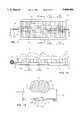
- FIG. 1illustrates a supine person and a plot showing pressure exerted on weight-bearing portions of the person's body by a surface that supports the body.
- FIG. 2is a top plan, partially schematic view of a preferred embodiment of the invention showing subdivision of a cooling layer into a plurality of zones.
- FIGS. 3 and 4are longitudinal sectional, partially schematic illustrations of the preferred embodiment of FIG. 2.
- FIG. 5is a schematic diagram showing control of the cooling zones of the preferred embodiment illustrated in FIG. 2.
- FIGS. 6 and 7are partially schematic, longitudinal sectional illustrations of a variation of the first preferred embodiment.
- FIG. 8is a partially schematic longitudinal section of a first alternate embodiment of the invention.
- FIG. 9is a longitudinal, partially schematic cross-section of the first alternate embodiment at section 9--9 of FIG. 8.
- FIG. 10is an enlargement of a portion of FIG. 9.
- FIG. 11is a top plan view of a second alternate embodiment of the invention.
- FIG. 12is a longitudinal sectional, partially schematic view taken along 12--12 of FIG. 11.
- FIG. 13is a cross sectional, partially schematic view taken along section 13--13 of FIG. 11.
- FIG. 1shows a supine person 12 resting on, which is to say supported by, a surface 14.
- a plot 15that represents pressure measured at the surface 14.
- the pressureis exerted by the weight-bearing portions of the body and has its peak magnitude in those areas where the body 12 contacts the surface 14.
- Note particularly that distinct pressure profilesare exhibited for the back of the head at 16, the upper back at 18, the buttocks at 20, the calves at 21, and the heels at 22. (The contributions of the elbows are not shown.)
- Theseare the areas of the body which bear much of the weight of the person, and they are referred to as "weight-bearing" areas.
- the weight-bearing areasthat include the buttocks and heels are at most risk for pressure injury.
- the inventionin its structure and operation, provides localized cooling to alleviate the effects of pressure acting between a support surface and the weight-bearing areas of a human or animal body.
- Localized coolingis provided by selectively operating zones of a multi-zone cooling layer to cool one or more portions of the support surface where weight-bearing areas of a supported human or animal body are borne, which consequently cools the weight-bearing areas.
- This principleis embodied preferably in an apparatus illustrated by the partially schematic cross-sectional drawings of FIGS. 2-4.
- the inventionincludes a cooling layer 30 that is divided into a plurality of zones, such as the zone 31.
- FIG. 2shows a top plan view of the cooling layer 30 with seven zones, one of which is the zone designated by the reference numeral 31.
- each of the zonescomprises a separate chamber of a flexible water mattress through which cooled water, below 37° C. (normal human temperature), can be circulated, independently of any other chamber.
- the chambersare rectangularly-shaped and each is comprised of one or more serpentine fluid channels formed by stake-point seals (such as the seal 32) that locally bond two sheets of material together.
- Each chamberhas its own respective inlet hose and outlet hose, the inlet hoses for all chambers being indicated by reference numeral 34 and the outlet hoses by reference numeral 36.
- each of the zones in the cooling layer 30 of the preferred embodimentoperates, refer in particular to the zone 31.
- the chamber of which the zone 31 is comprisedreceives a respective flow of cooled water through the inlet hose 34a and returns the respective flow of cooled water through the outlet hose 36a.
- an inlet flow of cooled water 37ais conducted to the zone 31 through the inlet hose 34a.
- the inlet flowdivides among the serpentine channels as indicated by 37b.
- the cooled waterflows through the chamber of the zone 31, exiting as indicated by 37c into the outlet hose 36a.
- water mattressis used in the description of this preferred embodiment, it should be understood that many different fluids could be circulated through a corresponding structure with a similar cooling effect.
- fluidsinclude, for example, glycol-water mixtures, alcohol-water mixtures, air, etc.
- the water mattress that embodies the cooling layer 30is divided into rectangular zones, with the longitudinal axis of each zone oriented substantially transversely with respect to the longitudinal axis A--A of a human body.
- each chamberwould preferably be in its transverse dimension at least half the width of the mattress. This permits cooling of a transverse segment of the body which is in high pressure contact with a support surface 40, without cooling adjacent, normally perfused, contact areas of the body, which could lead to general hypothermia and discomfort.
- This howeveris not intended to limit the subdivision of the cooling layer 30 into a parallel array of elongate, rectangular zones; indeed, the zones could be square or rectangular in shape and distributed within the cooling layer in a checkerboard pattern.
- each chamberis independently controlled.
- the fluid flowcan be manually controlled by a caregiver, or each chamber may have a corresponding pressure sensor to automatically initiate the flow of cooled fluid into, and through, that chamber when the pressure applied by the supported body against the support surface 40 exceeds a preselected threshold value.
- the preferred pressure sensing means in the embodiment illustrated in FIGS. 2-4comprise a piezoresistive pressure-sensitive film that is incorporated into a structure or member that includes or is contiguous with the support surface.
- the piezoresisitive pressure-sensitive filmwould have formed in it respective individual piezoresisitive pressure-sensitive areas that are illustrated in dashed outline in FIG. 2.
- One such piezoresistive pressure-sensitive areais indicated by reference numeral 39.
- Each of these areascomprises a respective pressure sensor.
- the pressure sensor 39comprises an elongated rectangular outline that is aligned, in plan, with the zone 31.
- each pressure sensoris aligned, as described above, with respect to a respective zone.
- FIG. 3shows a preferred structure for a mattress or a cushion that incorporates a support layer 42, preferably comprising a compressible material or structure in the form of a mattress.
- the cooling layer 30is in the form of a water mattress that can be similar in construction to a standard water mattress which is well known to the medical industry and may be obtained, for example, from Cincinnati Sub Zero Products, Cincinnati, Ohio, or Gaymar Industries, Orchard Park, N.Y., with the added feature of multiple, independent, preferably transverse fluid chambers.
- These mattressesare usually made of two sheets of flexible polyethylene or polyvinyl film, thermal formed into a labyrinth of fluid channels, and then heat sealed together. Water is circulated through such a mattress by an external pump with cooling capabilities. Circulating cooled water causes the water mattress to be a primary heat sink. The heat is ultimately dissipated into a secondary heat sink which is usually ambient air.
- the cooling meanscan be compression-based refrigeration cooling, thermo-electric based refrigeration cooling, radiator-based, ice-based, phase-change-material based, or based on any other suitable method that will maintain the circulating fluid at a temperature below the normal human body temperature 37° C.
- the cooling layeris located just beneath the surface 40 that supports at least a portion of a human or animal body.
- the structure that includes the surface 40may also integrate the pressure sensors 39, so that the pressure sensors lie between the surface 40 and the cooling layer 30. This is not intended to foreclose a structure in which the sensors 39 are disposed over or on the surface 40.
- the sensors 39also could be located beneath the cooling layer 30.
- the shaded area 44represents a portion of the human body supported on the surface 40.
- the lengths of the arrows 46, 47 and 48represent pressure exerted against the surface 40 by a weight-bearing portion of the body, such as the buttocks, and assuming further that pressure magnitudes represented by the lengths of those arrows exceed the magnitudes represented by the arrows 50 and 51, in the preferred embodiment cooled fluid is provided to the zones 31 that are aligned with the weight-bearing portion of the body indicated by the pressure profile 46, 47, 48.
- FIG. 5Means for selectively operating one or more zones of the plurality of zones in the cooling layer 30 to cool a portion of the surface 40 that receives pressure from a weight-bearing area of the body represented by shaded area 44 are illustrated in FIG. 5.
- the array of pressure sensors 39 including pressure sensor i and pressure sensor jprovide indications of pressures exerted against the surface 40 by a human or animal body.
- the pressure sensorsprovide voltage signals that are compared against a threshold voltage V th by a zone selector 50.
- the zone selectorcan comprise, for example substantially conventional threshold circuitry for processing signals from the pressure sensors.
- the zone selector 50For each pressure sensor providing a signal having a voltage magnitude exceeding V th , the zone selector 50 provides a signal that directs cooled fluid provided by a cooled fluid source 52 through a means 53 that may comprise, for example, a manifold.
- the fluid flow in each zonemay be controlled by a zone controller such as the zone controllers 55, each comprising, for example, a valve mechanism that initiates the flow of cooled fluid into the associated zone. This permits the provision of a separate, respective flow of cooled fluid into one or more zones of the cooling layer 30.
- each zone in the cooling layerwould have a known location with respect to the support surface.
- the caregiverwould note the location of weight-bearing areas known to be at risk for pressure injury and would activate the valve or valves necessary to initiate cooled fluid flow to the corresponding zones, thereby selectively cooling those specific skin areas at risk.
- Manual activation of zonesis illustrated, in FIG. 5, by the MANUAL CONTROL input on each zone controller 55.
- FIGS. 6 and 7show a variation of the preferred embodiment illustrated in FIGS. 3 and 4, with the addition of a relatively thin layer 60 of thermally-conductive material disposed between the cooling layer 30 and the surface 40.
- the layer 60is optional, and preferably comprises a pad of thermally conductive material which "evens out" the irregular upper surface that is an artifact of the thermo-formed channels in the water mattress embodying the cooling layer 30.
- the thermally-conductive material in the layer 60may include, for example, a polymeric gel, water, or another fluid.
- Pressure sensors 39may be disposed above, in, or below the thermally conductive layer 60.
- FIGS. 8-10illustrate a first alternate embodiment of the invention.
- the first alternate embodiment of the inventionis represented by an apparatus 80 having a patient support apparatus 82 which, in the figures is elongated to provide a cot-like structure that supports a supine person 81. It is to be understood that the first alternate embodiment is not intended to be limited strictly to support of a fully extended, reclining person, but is applicable as well to the support to less than all of a human or animal body.
- a cooling layerin the form of a manifold plenum structure 84 that is divided into zones for selective cooling in accordance with principles already discussed in the exposition of the preferred embodiment.
- the support apparatus 82includes a frame 85 for supporting the apparatus, for example, on a floor or other support surface, and a mesh 86 extending between, and anchored to, elongated parallel anchoring pipes 88.
- the manifold plenum structure 84is supported on a base 89 and includes two parallel, separated longitudinal air plenums 90 and a plurality of air plenums 93 disposed transversely with respect to the elongated longitudinal air plenums 90.
- the longitudinal air plenums 90communicate with the transverse air plenums 93 for conveyance of cooled air.
- One longitudinal air plenum 90includes a means for receiving a cooled air stream from a source of pressurized cooled air including the air cooling means 96 and blower 97.
- Each of the transverse air plenums 93is disposed beneath a respective portion of the mesh 86.
- the mesh 86comprises a support surface corresponding to support surface 40 discussed above, while the transverse air plenums 93 comprise a plurality of zones that are selectively controlled to cool elongated transverse portions of the mesh 86.
- Selective control of each air plenumis provided by an air jet slot valve 94 having a first, normally closed position covering an air jet slot 95, and a second, open position opening its associated air jet slot 95.
- the flow of pressurized airtravels through the longitudinal air plenums 90 and through all of the transverse air plenums 93, including the transverse air plenum 93 shown in FIG. 9.
- the transverse air plenum 93is positioned beneath the buttocks of the supine person 81 and has been operated to have its air jet slot valve 94 open in order to direct a flow of cooled air upwardly toward the mesh 86.
- the flow of cooled aircools the mesh 86 and the weight-bearing area in the buttocks of the person 81 that exerts pressure on the mesh 86 at the cross-sectional location.
- the air introduced by an air jet slot 95exits either from under the side and ends of the support apparatus 82, or through the mesh 86 (if the mesh is porous).
- FIG. 10is an enlarged illustration of a portion of the first alternative embodiment enclosed in the circle denoted by 100 in FIG. 9. The illustration is a mirror image of the corresponding section in the right-hand side of FIG. 9.
- the mesh 86is anchored to each of the elongated, parallel anchoring pipes 88 by a mesh anchoring flange 104 that is conventionally attached to the pipe 88 and which pinches the mesh 86 between itself and the pipe 88.
- a pressure transducer 102is disposed between the mesh 86 and the pipe 88.
- FIGS. 8-10shows, there are a plurality of pressure transducers 102 distributed along the anchoring pipes 88 such that each transverse air plenum 93 is aligned with a respective one of a plurality of pressure transducers 102.
- pressure transducerscan be arrayed in this or any suitable manner along one, or both, of the anchoring pipes 88.
- the patient 81is supported by a mesh that is preferably a woven fabric of synthetic, natural, metal, or glass fibers, or a combination thereof.
- the mesh 86has a loose weave so that air can pass through it.
- the transverse cooling zonesare defined by the transverse air plenums 93 that are, preferably, periodically spaced along the longitudinal dimension of the supine patient beneath the mesh 86.
- the air plenums 93can be arranged to form cooling zones of other shapes, such as a "checker-board" pattern.
- the air flow directed through the manifold plenum structure 84can either be cooled or at room temperature.
- Each air jet slot valve that selectively activates a plenummay be embodied by, for example, a simple door hinged longitudinally on the outside surface of a transverse air plenum 93 to open and shut over a corresponding air jet slot. Many other air valving means are feasible.
- each zone controllercan comprise, for example, an activator such as an electro-mechanical solenoid that mechanically opens and shuts the valve, thereby selectively providing air to blow on a portion of the mesh 86.
- the zone to be cooledcan be manually controlled by the caregiver by manual activation of a corresponding air jet slot valve 94.
- the sensor/zone selector combination illustrated in FIG. 5can be implemented using the structural elements illustrated in FIGS. 8-10.
- each of the sensors 102can comprise a piezoresistive pressure sensor.
- each air bladderis oriented in parallel with at least one adjacent air bladder, and transversely with respect to the longitudinal axis A--A of the supine person 81.
- Each of the air bladders 110includes an upper surface 111, and the upper surfaces 111 of the air bladders 110 collectively form the surface that supports the supine person 81.
- the surfacemay comprise a thin layer of compliant heat-conductive material contiguous with the upper surfaces of the air bladder.
- the rectangular air bladders 110are supported in an open, five-sided rectangular frame 112.
- the air bladders 110are made of flexible woven materials such as a synthetic fabric which may or may not be coated with a polymeric material, or bonded to a polymeric film.
- a first single elongated plenum 115 that encompasses the length of the frame 112receives a cooled air flow from 96, 97 and conveys it to the air bladders 110, each of which encompasses substantially the width of the frame 112.
- the first plenum 115feeds each air bladder through an air jet slot 117.
- Each air jet slot 117is controlled by an air jet slot valve 116 having an opened position, permitting cooled air to flow into, and circulate through, an air bladder 110, and having a closed position that prevents cooled air from flowing into the air bladder 110. Control of the air jet slot valves 116 can be as disclosed above in reference to the preferred and first alternate embodiments.
- the air jet slot valves 116are preferably solenoid-driven with solenoid control provided either by manually operated or automatically controlled means.
- an array of thin film pressure sensorscan be disposed in a single sheet across the upper surfaces 111 in such a manner as to align a sensor with each of the air bladders 110 for automatic control as illustrated above in connection with FIG. 5.
- Each air bladderincludes means for discharging air in a controlled manner, to allow continuous circulation of air within, and through, the bladder 110.
- the means for discharging aircan include migration through a controlled weave porosity of the fabric, air vents, or an air return duct.
- An air flow at higher temperature than the temperature of the cooled air flow delivered through the first plenum 115is generated by a fan 120 and heating element 121.
- a second, single elongate plenum 125receives the higher-temperature flow from 120, 121 and conducts it to the air bladders 110.
- the second plenum 125is provided for heating, if needed, and for maintaining the inflation of air bladders not receiving cooled air.
- the second plenum 125feeds each air bladder through an air jet slot 127 that is controlled by an air jet slot valve 126 having an opened position, permitting higher-temperature air to flow into, and circulate through, an air bladder 110, and having a closed position that prevents higher-temperature air from flowing into the air bladder 110.
- Control of the air jet slot valves 126can be as disclosed above in reference to the preferred and first alternate embodiments.
- the air jet slot valves 126are preferably solenoid-driven with solenoid control provided either by manually operated or automatically controlled means.
- the array of thin film pressure sensorscan be processed by a voltage threshold V th , with a pressure sensor generating a voltage above this threshold in response to weight-bearing pressure, which will automatically close the air jet slot valve 126 and open the air jet slot valve 116, permitting cooled air to circulate into and through the air bladder.
- the air jet slot valves 116would be closed, while the air jet slot valves 126 would be open. This reciprocal operation will maintain all air bladders at some predetermined state of inflation or distention in response to circulating air, thereby ensuring a uniform support of the body 81 across the surface that supports the body.
Landscapes
- Health & Medical Sciences (AREA)
- Vascular Medicine (AREA)
- Animal Behavior & Ethology (AREA)
- Engineering & Computer Science (AREA)
- Biomedical Technology (AREA)
- Heart & Thoracic Surgery (AREA)
- Physics & Mathematics (AREA)
- Life Sciences & Earth Sciences (AREA)
- Thermal Sciences (AREA)
- General Health & Medical Sciences (AREA)
- Public Health (AREA)
- Veterinary Medicine (AREA)
- Thermotherapy And Cooling Therapy Devices (AREA)
- Invalid Beds And Related Equipment (AREA)
- Housing For Livestock And Birds (AREA)
Abstract
Description
Claims (20)
Priority Applications (6)
| Application Number | Priority Date | Filing Date | Title |
|---|---|---|---|
| US08/707,967US5800480A (en) | 1996-08-30 | 1996-08-30 | Support apparatus with a plurality of thermal zones providing localized cooling |
| CA002213949ACA2213949C (en) | 1996-08-30 | 1997-08-20 | Support apparatus with a plurality of thermal zones providing localized cooling |
| MX9706560AMX9706560A (en) | 1996-08-30 | 1997-08-28 | Support apparatus with a plurality of thermal zones providing localized cooling. |
| US09/020,079US6033432A (en) | 1996-08-30 | 1998-02-06 | Support apparatus with a plurality of thermal zones providing localized cooling |
| US09/473,325US6210427B1 (en) | 1996-08-30 | 1999-12-28 | Support apparatus with a plurality of thermal zones providing localized cooling |
| US09/758,062US6497720B1 (en) | 1996-08-30 | 2001-01-10 | Support apparatus with a plurality of thermal zones providing localized cooling |
Applications Claiming Priority (1)
| Application Number | Priority Date | Filing Date | Title |
|---|---|---|---|
| US08/707,967US5800480A (en) | 1996-08-30 | 1996-08-30 | Support apparatus with a plurality of thermal zones providing localized cooling |
Related Child Applications (1)
| Application Number | Title | Priority Date | Filing Date |
|---|---|---|---|
| US09/020,079ContinuationUS6033432A (en) | 1996-08-30 | 1998-02-06 | Support apparatus with a plurality of thermal zones providing localized cooling |
Publications (1)
| Publication Number | Publication Date |
|---|---|
| US5800480Atrue US5800480A (en) | 1998-09-01 |
Family
ID=24843880
Family Applications (4)
| Application Number | Title | Priority Date | Filing Date |
|---|---|---|---|
| US08/707,967Expired - LifetimeUS5800480A (en) | 1996-08-30 | 1996-08-30 | Support apparatus with a plurality of thermal zones providing localized cooling |
| US09/020,079Expired - Fee RelatedUS6033432A (en) | 1996-08-30 | 1998-02-06 | Support apparatus with a plurality of thermal zones providing localized cooling |
| US09/473,325Expired - LifetimeUS6210427B1 (en) | 1996-08-30 | 1999-12-28 | Support apparatus with a plurality of thermal zones providing localized cooling |
| US09/758,062Expired - Fee RelatedUS6497720B1 (en) | 1996-08-30 | 2001-01-10 | Support apparatus with a plurality of thermal zones providing localized cooling |
Family Applications After (3)
| Application Number | Title | Priority Date | Filing Date |
|---|---|---|---|
| US09/020,079Expired - Fee RelatedUS6033432A (en) | 1996-08-30 | 1998-02-06 | Support apparatus with a plurality of thermal zones providing localized cooling |
| US09/473,325Expired - LifetimeUS6210427B1 (en) | 1996-08-30 | 1999-12-28 | Support apparatus with a plurality of thermal zones providing localized cooling |
| US09/758,062Expired - Fee RelatedUS6497720B1 (en) | 1996-08-30 | 2001-01-10 | Support apparatus with a plurality of thermal zones providing localized cooling |
Country Status (3)
| Country | Link |
|---|---|
| US (4) | US5800480A (en) |
| CA (1) | CA2213949C (en) |
| MX (1) | MX9706560A (en) |
Cited By (94)
| Publication number | Priority date | Publication date | Assignee | Title |
|---|---|---|---|---|
| US6033432A (en)* | 1996-08-30 | 2000-03-07 | Augustine Medical, Inc. | Support apparatus with a plurality of thermal zones providing localized cooling |
| US6067019A (en)* | 1996-11-25 | 2000-05-23 | Hill-Rom, Inc. | Bed exit detection apparatus |
| US6096068A (en)* | 1998-01-23 | 2000-08-01 | Innercool Therapies, Inc. | Selective organ cooling catheter and method of using the same |
| US6133837A (en)* | 1999-03-05 | 2000-10-17 | Hill-Rom, Inc. | Patient position system and method for a support surface |
| US6149677A (en)* | 1998-03-31 | 2000-11-21 | Innercool Therapies, Inc. | Circulating fluid hypothermia method |
| US6224624B1 (en) | 1998-03-24 | 2001-05-01 | Innercool Therapies, Inc. | Selective organ cooling apparatus and method |
| US6235048B1 (en) | 1998-01-23 | 2001-05-22 | Innercool Therapies, Inc. | Selective organ hypothermia method and apparatus |
| US6238428B1 (en) | 1998-01-23 | 2001-05-29 | Innercool Therapies, Inc. | Selective organ cooling apparatus and method employing turbulence-inducing element with curved terminations |
| US6245095B1 (en) | 1998-03-24 | 2001-06-12 | Innercool Therapies, Inc. | Method and apparatus for location and temperature specific drug action such as thrombolysis |
| US6251130B1 (en) | 1998-03-24 | 2001-06-26 | Innercool Therapies, Inc. | Device for applications of selective organ cooling |
| US6251129B1 (en) | 1998-03-24 | 2001-06-26 | Innercool Therapies, Inc. | Method for low temperature thrombolysis and low temperature thrombolytic agent with selective organ temperature control |
| US6254626B1 (en) | 1998-03-24 | 2001-07-03 | Innercool Therapies, Inc. | Articulation device for selective organ cooling apparatus |
| US6261312B1 (en) | 1998-06-23 | 2001-07-17 | Innercool Therapies, Inc. | Inflatable catheter for selective organ heating and cooling and method of using the same |
| US6273810B1 (en) | 1999-09-10 | 2001-08-14 | Mccord Winn Textron Inc. | Inflatable air cell having combined pneumatically adjusted occupant support and thermal conditioning |
| US6312452B1 (en) | 1998-01-23 | 2001-11-06 | Innercool Therapies, Inc. | Selective organ cooling catheter with guidewire apparatus and temperature-monitoring device |
| US6325818B1 (en) | 1999-10-07 | 2001-12-04 | Innercool Therapies, Inc. | Inflatable cooling apparatus for selective organ hypothermia |
| US6447865B1 (en) | 1998-07-22 | 2002-09-10 | Gaymar Industries, Inc. | Gelatinous composite article and construction |
| US6464716B1 (en) | 1998-01-23 | 2002-10-15 | Innercool Therapies, Inc. | Selective organ cooling apparatus and method |
| US6471717B1 (en) | 1998-03-24 | 2002-10-29 | Innercool Therapies, Inc. | Selective organ cooling apparatus and method |
| US6491716B2 (en) | 1998-03-24 | 2002-12-10 | Innercool Therapies, Inc. | Method and device for applications of selective organ cooling |
| US6491039B1 (en) | 1998-01-23 | 2002-12-10 | Innercool Therapies, Inc. | Medical procedure |
| US6551349B2 (en) | 1998-03-24 | 2003-04-22 | Innercool Therapies, Inc. | Selective organ cooling apparatus |
| US6559422B2 (en) | 2000-08-17 | 2003-05-06 | Ctex Seat Comfort Limited | Expandable chamber having combined occupant support and heating |
| US6558412B2 (en) | 1998-01-23 | 2003-05-06 | Innercool Therapies, Inc. | Selective organ hypothermia method and apparatus |
| US6576002B2 (en) | 1998-03-24 | 2003-06-10 | Innercool Therapies, Inc. | Isolated selective organ cooling method and apparatus |
| US6576001B2 (en) | 2000-03-03 | 2003-06-10 | Innercool Therapies, Inc. | Lumen design for catheter |
| US6585752B2 (en) | 1998-06-23 | 2003-07-01 | Innercool Therapies, Inc. | Fever regulation method and apparatus |
| US6599312B2 (en) | 1998-03-24 | 2003-07-29 | Innercool Therapies, Inc. | Isolated selective organ cooling apparatus |
| US6602276B2 (en) | 1998-03-31 | 2003-08-05 | Innercool Therapies, Inc. | Method and device for performing cooling- or cryo-therapies for, e.g., angioplasty with reduced restenosis or pulmonary vein cell necrosis to inhibit atrial fibrillation |
| US6606754B1 (en) | 1999-03-30 | 2003-08-19 | Gaymar Industries, Inc. | Supported hypo/hyperthermia pad |
| US6660028B2 (en) | 2000-06-02 | 2003-12-09 | Innercool Therapies, Inc. | Method for determining the effective thermal mass of a body or organ using a cooling catheter |
| US6685732B2 (en) | 1998-03-31 | 2004-02-03 | Innercool Therapies, Inc. | Method and device for performing cooling- or cryo-therapies for, e.g., angioplasty with reduced restenosis or pulmonary vein cell necrosis to inhibit atrial fibrillation employing microporous balloon |
| US6699266B2 (en) | 2001-12-08 | 2004-03-02 | Charles A. Lachenbruch | Support surface with phase change material or heat tubes |
| US6719779B2 (en) | 2000-11-07 | 2004-04-13 | Innercool Therapies, Inc. | Circulation set for temperature-controlled catheter and method of using the same |
| US6726708B2 (en) | 2000-06-14 | 2004-04-27 | Innercool Therapies, Inc. | Therapeutic heating and cooling via temperature management of a colon-inserted balloon |
| US6772825B2 (en) | 2002-11-04 | 2004-08-10 | Charles A. Lachenbruch | Heat exchange support surface |
| US20040225341A1 (en)* | 2002-07-11 | 2004-11-11 | Life Recovery Systems, Inc. | Apparatus for altering the body temperature of a patient |
| US6830581B2 (en) | 1999-02-09 | 2004-12-14 | Innercool Therspies, Inc. | Method and device for patient temperature control employing optimized rewarming |
| US6843800B1 (en) | 1998-01-23 | 2005-01-18 | Innercool Therapies, Inc. | Patient temperature regulation method and apparatus |
| US6869440B2 (en) | 1999-02-09 | 2005-03-22 | Innercool Therapies, Inc. | Method and apparatus for patient temperature control employing administration of anti-shivering agents |
| US6905494B2 (en) | 1998-03-31 | 2005-06-14 | Innercool Therapies, Inc. | Method and device for performing cooling- or cryo-therapies for, e.g., angioplasty with reduced restenosis or pulmonary vein cell necrosis to inhibit atrial fibrillation employing tissue protection |
| US6991645B2 (en) | 1998-01-23 | 2006-01-31 | Innercool Therapies, Inc. | Patient temperature regulation method and apparatus |
| US7001378B2 (en) | 1998-03-31 | 2006-02-21 | Innercool Therapies, Inc. | Method and device for performing cooling or cryo-therapies, for, e.g., angioplasty with reduced restenosis or pulmonary vein cell necrosis to inhibit atrial fibrillation employing tissue protection |
| US20060069418A1 (en)* | 2004-09-24 | 2006-03-30 | Schock Robert B | Apparatus for altering the body temperature of a patient |
| US7036162B1 (en)* | 2003-09-10 | 2006-05-02 | Gatten Kenneth W | Cooling mattress for sunbathing |
| USD551349S1 (en) | 2006-08-24 | 2007-09-18 | Life Recovery Systems Hd, Llc | Pneumatic mattress |
| US7291144B2 (en) | 1998-03-31 | 2007-11-06 | Innercool Therapies, Inc. | Method and device for performing cooling- or cryo-therapies for, e.g., angioplasty with reduced restenosis or pulmonary vein cell necrosis to inhibit atrial fibrillation |
| US7300453B2 (en) | 2003-02-24 | 2007-11-27 | Innercool Therapies, Inc. | System and method for inducing hypothermia with control and determination of catheter pressure |
| US7371254B2 (en) | 1998-01-23 | 2008-05-13 | Innercool Therapies, Inc. | Medical procedure |
| US7422600B2 (en) | 1999-02-09 | 2008-09-09 | Innercool Therapies, Inc. | Method and apparatus for patient temperature control employing administration of anti-shivering agents |
| JP2008544805A (en)* | 2005-07-05 | 2008-12-11 | ケーシーアイ ライセンシング インコーポレイテッド | Portable therapeutic cooling system |
| US7547320B2 (en) | 2002-07-11 | 2009-06-16 | Life Recovery System Hd, Llc | Apparatus for altering the body temperature of a patient |
| US20090227923A1 (en)* | 2008-03-07 | 2009-09-10 | Markus Christopher A | Cooling system for orthopedic cast |
| US20100018327A1 (en)* | 2005-06-21 | 2010-01-28 | Aisin Seiki Kabushiki Kaisha | Load detecting apparatus and load detecting method |
| US7666213B2 (en) | 2002-07-11 | 2010-02-23 | Life Recovery Systems Hd, Llc | Apparatus for altering the body temperature of a patient |
| EP1487386A4 (en)* | 2002-02-27 | 2010-04-07 | Medivance Inc | Improved medical thermal energy exchange pad |
| US20100161013A1 (en)* | 2004-07-02 | 2010-06-24 | Kci Licensing, Inc. | Portable Therapeutic Cooling System |
| US7771461B2 (en) | 2006-08-24 | 2010-08-10 | Life Recovery Systems Hd, Llc | Apparatus for altering the body temperature of a patient |
| US20100204764A1 (en)* | 2009-02-11 | 2010-08-12 | Garetz Bruce A | Method for Treating Hot Flashes Associated with Menopause During Sleep |
| US20100308846A1 (en)* | 2009-06-05 | 2010-12-09 | Gilles Camus | Pressure sensor comprising a capacitive cell and support device comprising said sensor |
| US7857781B2 (en) | 1998-04-21 | 2010-12-28 | Zoll Circulation, Inc. | Indwelling heat exchange catheter and method of using same |
| US20100325796A1 (en)* | 2009-06-29 | 2010-12-30 | Lachenbruch Charles A | Localized Microclimate Management |
| US20110024076A1 (en)* | 2008-04-15 | 2011-02-03 | Hill-Rom Services, Inc. | Microclimate management system |
| JP2011206556A (en)* | 2011-06-07 | 2011-10-20 | Kci Licensing Inc | Portable cooling system for treatment |
| US8161826B1 (en)* | 2009-03-05 | 2012-04-24 | Stryker Corporation | Elastically stretchable fabric force sensor arrays and methods of making |
| US8182520B2 (en) | 2006-12-07 | 2012-05-22 | Life Recovery Systems Hd, Llc | Apparatus for altering the body temperature of a patient |
| US20130091961A1 (en)* | 2011-10-12 | 2013-04-18 | Stryker Corporation | Pressure sensing mat |
| WO2013076628A1 (en)* | 2011-11-21 | 2013-05-30 | Koninklijke Philips Electronics N.V. | A system and a method for improving a person's sleep |
| US8584286B2 (en) | 2010-04-27 | 2013-11-19 | Ec Service Inc. | Systems and methods for providing a self deflating cushion |
| US8856993B2 (en) | 2008-04-15 | 2014-10-14 | Hill-Rom Services, Inc. | Temperature and moisture regulating topper for non-powered person-support surfaces |
| US8904876B2 (en) | 2012-09-29 | 2014-12-09 | Stryker Corporation | Flexible piezocapacitive and piezoresistive force and pressure sensors |
| US20150033474A1 (en)* | 2012-10-18 | 2015-02-05 | Tempur-Pedic Management, Llc | Support cushions and methods for controlling surface temperature of same |
| US8997588B2 (en) | 2012-09-29 | 2015-04-07 | Stryker Corporation | Force detecting mat with multiple sensor types |
| US20150208815A1 (en)* | 2012-10-18 | 2015-07-30 | Tempur-Pedic Management, Llc | Support cushions including reticulated materials and methods for controlling surface temperature of same |
| US20150341989A1 (en)* | 2014-05-21 | 2015-11-26 | Bell Helicopter Textron Inc. | Variable stiffness blanket with variable heating |
| US9333136B2 (en) | 2013-02-28 | 2016-05-10 | Hill-Rom Services, Inc. | Sensors in a mattress cover |
| US20160286972A1 (en)* | 2015-04-01 | 2016-10-06 | Dreamwell, Ltd. | Mattress assembly including thermally conductive foam layer |
| US9463124B2 (en) | 2013-01-15 | 2016-10-11 | Hill-Rom Services, Inc. | Microclimate system for a patient support apparatus |
| US20180185224A1 (en)* | 2016-12-29 | 2018-07-05 | Hill-Rom Services, Inc. | Support apparatuses comprising cooling elements |
| US10179064B2 (en) | 2014-05-09 | 2019-01-15 | Sleepnea Llc | WhipFlash [TM]: wearable environmental control system for predicting and cooling hot flashes |
| US10477978B1 (en) | 2008-07-30 | 2019-11-19 | Youngblood Ip Holdings, Llc | Multi-zone temperature modulation system for bed or blanket |
| ES2734949A1 (en)* | 2018-06-08 | 2019-12-12 | Rade Tecnologias Sl | STRETCHER (Machine-translation by Google Translate, not legally binding) |
| US10555848B2 (en) | 2017-04-29 | 2020-02-11 | Harikrishan S. Sachdev | Portable cushion and method of use |
| US20210038453A1 (en)* | 2009-08-31 | 2021-02-11 | Gentherm Incorporated | Climate-controlled topper member for beds |
| US20210162899A1 (en)* | 2017-10-27 | 2021-06-03 | Gentherm Gmbh | Surface temperature-controlling device |
| US11191687B2 (en) | 2017-04-29 | 2021-12-07 | Harikrishan S. Sachdev | Portable cushion and method of use |
| US11246746B2 (en)* | 2017-12-21 | 2022-02-15 | Stryker Corporation | Thermal transfer device for providing thermal treatment to a patient |
| WO2022231953A1 (en)* | 2021-04-29 | 2022-11-03 | Holtquist Zachariah Clarence | Mattress |
| US11559421B2 (en) | 2015-06-25 | 2023-01-24 | Hill-Rom Services, Inc. | Protective dressing with reusable phase-change material cooling insert |
| US11583437B2 (en) | 2018-02-06 | 2023-02-21 | Aspen Surgical Products, Inc. | Reusable warming blanket with phase change material |
| WO2024022632A1 (en)* | 2022-07-29 | 2024-02-01 | Thomas Hausmann | Apparatus for completely enveloping a human or animal body, and method for operating such an apparatus |
| US11904103B2 (en) | 2018-01-19 | 2024-02-20 | Eight Sleep Inc. | Sleep pod |
| US12053591B2 (en) | 2014-06-05 | 2024-08-06 | Eight Sleep Inc. | Methods and systems for gathering and analyzing human biological signals |
| US12274564B2 (en) | 2018-01-09 | 2025-04-15 | Eight Sleep Inc. | Systems and methods for detecting a biological signal of a user of an article of furniture |
Families Citing this family (76)
| Publication number | Priority date | Publication date | Assignee | Title |
|---|---|---|---|---|
| BR9911568A (en) | 1998-06-26 | 2001-09-18 | Hill Rom Co Inc | Apparatus for warming up a patient |
| US7555792B2 (en)* | 1998-11-06 | 2009-07-07 | Kci Licensing, Inc. | Patient cooling enclosure |
| US7226471B2 (en)* | 2002-11-08 | 2007-06-05 | Kci Licensing, Inc. | Patient cooling system |
| US7507249B2 (en)* | 2002-11-08 | 2009-03-24 | Kci Licensing, Inc. | Patient cooling system |
| US6945987B2 (en)* | 2002-11-08 | 2005-09-20 | Kci Licensing, Inc. | Patient cooling system |
| ES2241335T3 (en) | 1998-11-06 | 2005-10-16 | Kci Licensing, Inc. | RECEPTACLE FOR COOLING PATIENTS. |
| DE60023118T2 (en) | 1999-01-04 | 2006-07-13 | Medivance, Inc., Louisville | IMPROVED COOLING / HEATING CUSHION AND SYSTEM |
| US6419691B1 (en)* | 2000-03-23 | 2002-07-16 | Milene H. Hanner | Thermal energy therapy |
| AT409931B (en)* | 2001-01-30 | 2002-12-27 | Gluderer Lothar Erich | FOIL WANNENBIOSTEUERUNG |
| US6461379B1 (en)* | 2001-04-30 | 2002-10-08 | Medivance, Incorporated | Localized bodily cooling/heating apparatus and method |
| AU2002309987A1 (en)* | 2001-05-25 | 2002-12-09 | Hill-Rom Services, Inc. | Modular patient room |
| US20040243026A1 (en)* | 2001-07-25 | 2004-12-02 | Joerg Toepfer | Thermal applicator and application system |
| US6855158B2 (en) | 2001-09-11 | 2005-02-15 | Hill-Rom Services, Inc. | Thermo-regulating patient support structure |
| US6660027B2 (en) | 2001-10-11 | 2003-12-09 | Medivance Incorporated | Patient temperature control system with fluid preconditioning |
| US6818012B2 (en) | 2001-10-11 | 2004-11-16 | Medivance, Incorporated | Patient temperature control system with fluid temperature response |
| US6699267B2 (en)* | 2001-10-11 | 2004-03-02 | Medivance Incorporated | Patient temperature control system with fluid temperature response |
| US7008445B2 (en) | 2002-04-29 | 2006-03-07 | Medcool, Inc. | Method and device for rapidly inducing hypothermia |
| US7052509B2 (en)* | 2002-04-29 | 2006-05-30 | Medcool, Inc. | Method and device for rapidly inducing and then maintaining hypothermia |
| US7087075B2 (en) | 2002-09-30 | 2006-08-08 | Medtronic Emergency Response Systems, Inc. | Feedback system for rapid induction of mild hypothermia |
| US7179279B2 (en) | 2002-09-30 | 2007-02-20 | Medtronic Physio Control Corp. | Rapid induction of mild hypothermia |
| US7434459B2 (en)* | 2002-09-30 | 2008-10-14 | Sap Aktiengesellschaft | Context acquisition based on load sensing |
| JP4658612B2 (en)* | 2002-12-12 | 2011-03-23 | メドクール・インコーポレイテッド | Method and apparatus for rapidly inducing and maintaining hypothermia |
| US7056282B2 (en) | 2002-12-23 | 2006-06-06 | Medtronic Emergency Response Systems, Inc. | Coolant control for rapid induction of mild hypothermia |
| US6734398B1 (en)* | 2003-01-29 | 2004-05-11 | Michael D. Cecchi | Bladder system for controlling the temperature of laboratory fume hoods and working surfaces |
| DE602004027485D1 (en)* | 2003-06-13 | 2010-07-15 | Summerville S C | SELF-SUPPORTING SKIN-COOLING SUPPLEMENTS |
| US6962600B2 (en)* | 2003-08-04 | 2005-11-08 | Medcool, Inc. | Method and apparatus for reducing body temperature of a subject |
| US20050150049A1 (en)* | 2004-01-12 | 2005-07-14 | Schmidt Hans E. | Sleeping devices comprising a combination of down filling and a temperature regulating material |
| US7056116B2 (en)* | 2004-10-26 | 2006-06-06 | Ultradent Products, Inc. | Heat sink for dental curing light comprising a plurality of different materials |
| US8491644B1 (en) | 2005-02-22 | 2013-07-23 | Medivance Incorporated | Portable, refrigerant-based apparatus and method for rapid systemic patient cooling |
| US20080269852A1 (en)* | 2005-04-07 | 2008-10-30 | Medcool, Inc | Methods and Apparatus for Thermal Regulation of a Body |
| DK176826B1 (en)* | 2005-05-19 | 2009-11-09 | Quilts Of Denmark As | Mattress comprising an active heat-absorbing / emitting layer in combination with a layer of spacer material |
| US20080262579A1 (en)* | 2006-04-14 | 2008-10-23 | Berk Kevin J | Exercise method and apparatus which provides therapeutic modalities and reflexology |
| US7708338B2 (en)* | 2006-10-10 | 2010-05-04 | Amerigon Incorporated | Ventilation system for seat |
| EP2567637B1 (en) | 2006-10-13 | 2014-08-06 | Gentherm Incorporated | Air conditioning bed |
| US20080097561A1 (en)* | 2006-10-18 | 2008-04-24 | Medcool, Inc. | Dual cycle thermal system and method of use |
| US8529613B2 (en) | 2006-10-18 | 2013-09-10 | Medcool, Inc. | Adjustable thermal cap |
| US20080221493A1 (en)* | 2006-12-07 | 2008-09-11 | Life Recovery Systems Hd, Llc | Apparatus for altering the body temperature of a patient and administering decompression to the patients torso |
| WO2008101034A2 (en)* | 2007-02-13 | 2008-08-21 | Thermotek, Inc. | System and method for cooled airflow for dermatological applications |
| US20150366367A1 (en) | 2007-03-19 | 2015-12-24 | Augustine Temperature Management LLC | Electric heating pad with electrosurgical grounding |
| US10201935B2 (en) | 2007-03-19 | 2019-02-12 | Augustine Temperature Management LLC | Electric heating pad |
| US8283602B2 (en) | 2007-03-19 | 2012-10-09 | Augustine Temperature Management LLC | Heating blanket |
| WO2009036077A1 (en) | 2007-09-10 | 2009-03-19 | Amerigon, Inc. | Operational control schemes for ventilated seat or bed assemblies |
| US9125497B2 (en) | 2007-10-15 | 2015-09-08 | Gentherm Incorporated | Climate controlled bed assembly with intermediate layer |
| US8181290B2 (en) | 2008-07-18 | 2012-05-22 | Amerigon Incorporated | Climate controlled bed assembly |
| US9962284B2 (en)* | 2007-12-19 | 2018-05-08 | Johnson & Johnson Consumer Inc. | Thermal treatment device |
| WO2009108611A1 (en)* | 2008-02-25 | 2009-09-03 | Mc Neil-Ppc, Inc. | Thermal treatment device |
| US20100161014A1 (en)* | 2008-12-23 | 2010-06-24 | Lynch Joseph M | Thermal treatment device |
| US8893329B2 (en) | 2009-05-06 | 2014-11-25 | Gentherm Incorporated | Control schemes and features for climate-controlled beds |
| US20110092890A1 (en)* | 2009-10-20 | 2011-04-21 | Stryker Corporation | Microclimate management system |
| US20140183403A1 (en) | 2012-12-27 | 2014-07-03 | Peterson Chemical Technology, Inc. | Increasing the Heat Flow of Flexible Cellular Foam Through the Incorporation of Highly Thermally Conductive Solids |
| WO2011106600A2 (en) | 2010-02-26 | 2011-09-01 | 3M Innovative Properties Company | Patient support systems and methods for transferring patients and controlling patient temperature |
| US20110216013A1 (en)* | 2010-03-05 | 2011-09-08 | Sony Ericsson Mobile Communications Ab | Touch-sensitive input device, touch screen device, mobile device and method for operating a touch-sensitive input device |
| US8720218B2 (en)* | 2010-04-14 | 2014-05-13 | The Green Pet Shop Enterprises, Llc | Pressure activated recharging cooling platform |
| US10010446B2 (en)* | 2011-01-05 | 2018-07-03 | Hill-Rom Services, Inc. | Cooling system for an occupant of an occupant support and a cooling garment |
| WO2012125916A2 (en)* | 2011-03-16 | 2012-09-20 | Augustine Temperature Management, Llc | Heated under-body warming system |
| US20130046153A1 (en) | 2011-08-16 | 2013-02-21 | Elwha LLC, a limited liability company of the State of Delaware | Systematic distillation of status data relating to regimen compliance |
| US20130238042A1 (en) | 2012-03-12 | 2013-09-12 | Richard Gildersleeve | Systems and methods for providing temperature-controlled therapy |
| US10051973B2 (en) | 2012-07-31 | 2018-08-21 | Sealy Technology Llc | Air conditioned mattresses |
| US20140094884A1 (en)* | 2012-10-01 | 2014-04-03 | Zaheer Zaidi | Warming system |
| US9131781B2 (en) | 2012-12-27 | 2015-09-15 | Select Comfort Corporation | Distribution pad for a temperature control system |
| US20140316495A1 (en) | 2013-04-17 | 2014-10-23 | Augustine Biomedical And Design, Llc | Conformable heated mattress |
| RU2555379C1 (en)* | 2014-02-11 | 2015-07-10 | Антон Александрович Касаткин | Cooling device |
| US9962122B2 (en) | 2014-04-10 | 2018-05-08 | Augustine Temperature Management LLC | Underbody warming systems |
| WO2016077742A1 (en) | 2014-11-13 | 2016-05-19 | Augustine Temperature Management, Llc | Heated underbody warming systems with electrosurgical grounding |
| CA2986464A1 (en)* | 2015-05-21 | 2016-11-24 | Vitaheat Medical, Llc | Patient warming system |
| US10765577B2 (en) | 2015-06-30 | 2020-09-08 | Hill-Rom Services, Inc. | Microclimate system for a patient support apparatus |
| EP3167765B1 (en) | 2015-11-13 | 2023-08-23 | Hill-Rom Services, Inc. | Person support systems with cooling features |
| US10842288B2 (en) | 2017-01-31 | 2020-11-24 | Hill-Rom Services, Inc. | Person support systems with cooling features |
| US10772438B2 (en) | 2017-08-23 | 2020-09-15 | Sleep Number Corporation | Air system for a bed |
| US12225879B2 (en) | 2017-10-13 | 2025-02-18 | Maranda Enterprises, LLC | Animal cooling mat |
| US11570970B2 (en) | 2017-10-13 | 2023-02-07 | Maranda Enterprises | Dog cooling system |
| US11785916B1 (en) | 2017-12-04 | 2023-10-17 | Maranda Enterprises | Animal cooling mat |
| US10765580B1 (en) | 2019-03-27 | 2020-09-08 | Augustine Biomedical And Design, Llc | Patient securement system for the surgical trendelenburg position |
| US11814566B2 (en) | 2020-07-13 | 2023-11-14 | L&P Property Management Company | Thermally conductive nanomaterials in flexible foam |
| US11597862B2 (en) | 2021-03-10 | 2023-03-07 | L&P Property Management Company | Thermally conductive nanomaterial coatings on flexible foam or fabrics |
| US11844733B1 (en) | 2022-06-23 | 2023-12-19 | Augustine Biomedical And Design, Llc | Patient securement system for the surgical Trendelenburg position |
Citations (24)
| Publication number | Priority date | Publication date | Assignee | Title |
|---|---|---|---|---|
| US3289748A (en)* | 1964-09-04 | 1966-12-06 | United Aircraft Corp | Heat transfer garment |
| US3738702A (en)* | 1972-03-15 | 1973-06-12 | Gen Motors Corp | Means for cooling and heating a seat structure |
| US4026299A (en)* | 1975-09-26 | 1977-05-31 | Vari-Temp Manufacturing Co. | Cooling and heating apparatus |
| US4114620A (en)* | 1977-03-02 | 1978-09-19 | Moore-Perk Corporation | Patient treatment pad for hot or cold use |
| US4149541A (en)* | 1977-10-06 | 1979-04-17 | Moore-Perk Corporation | Fluid circulating pad |
| US4416281A (en)* | 1981-03-05 | 1983-11-22 | Guardline Disposables Limited | Surgical cushion for cooling an organ |
| US4706672A (en)* | 1983-09-26 | 1987-11-17 | Jones Robert C | Therapeutic thermal transfer device |
| US4844072A (en)* | 1985-12-27 | 1989-07-04 | Seabrook Medical Systems, Inc. | Liquid-circulating thermal therapy system |
| US4884304A (en)* | 1988-09-28 | 1989-12-05 | Life Support Systems, Inc. | Bedding system with selective heating and cooling |
| US4886063A (en)* | 1988-06-29 | 1989-12-12 | Crews Beverly J | Reusable therapeutic device |
| US4962761A (en)* | 1987-02-24 | 1990-10-16 | Golden Theodore A | Thermal bandage |
| US4966145A (en)* | 1987-03-19 | 1990-10-30 | Agency Of Industrial Science & Technology | Automatic body temperature adjuster |
| US5072875A (en)* | 1990-03-15 | 1991-12-17 | Federal Leasing Rehab Company | Apparatus for controlling the temperature of an area of the body |
| US5097829A (en)* | 1990-03-19 | 1992-03-24 | Tony Quisenberry | Temperature controlled cooling system |
| US5138138A (en)* | 1988-02-03 | 1992-08-11 | Stihler Electronic Medizintechnische Gerate Prod. Und Vertriebs-Gmbh | Heating system for an operating table |
| US5169384A (en)* | 1991-08-16 | 1992-12-08 | Bosniak Stephen L | Apparatus for facilitating post-traumatic, post-surgical, and/or post-inflammatory healing of tissue |
| US5174285A (en)* | 1990-01-08 | 1992-12-29 | Lake Shore Medical Development Partners Ltd. | Localized heat transfer device |
| US5176424A (en)* | 1988-06-10 | 1993-01-05 | Mazda Motor Corporation | Automobile seat assembly |
| US5183039A (en)* | 1991-08-23 | 1993-02-02 | Baxter International Inc. | Temperature control device for fluid filled pad |
| US5269369A (en)* | 1991-11-18 | 1993-12-14 | Wright State University | Temperature regulation system for the human body using heat pipes |
| US5433083A (en)* | 1989-09-29 | 1995-07-18 | Kuramarohit; Kullapat | Cooling garment |
| US5448788A (en)* | 1994-03-08 | 1995-09-12 | Wu; Shuenn-Jenq | Thermoelectric cooling-heating mattress |
| US5456701A (en)* | 1994-02-25 | 1995-10-10 | Southwest Technologies, Inc. | Therapy member including internal bladder with surrounding pliable gel |
| US5486206A (en)* | 1991-11-15 | 1996-01-23 | P.I., Inc. | Reusable thermal pack and flow retardant gel for use therein |
Family Cites Families (4)
| Publication number | Priority date | Publication date | Assignee | Title |
|---|---|---|---|---|
| US3757366A (en)* | 1971-08-18 | 1973-09-11 | W Sacher | Cushion for preventing and alleviating bedsores |
| US4788730A (en)* | 1987-12-02 | 1988-12-06 | Bexton Robert A | Gel-filled, variably-adjustable cushioning system for supporting a person |
| US5800480A (en)* | 1996-08-30 | 1998-09-01 | Augustine Medical, Inc. | Support apparatus with a plurality of thermal zones providing localized cooling |
| US6263530B1 (en)* | 1996-09-24 | 2001-07-24 | Steve Feher | Selectively cooled or heated cushion and apparatus therefor |
- 1996
- 1996-08-30USUS08/707,967patent/US5800480A/ennot_activeExpired - Lifetime
- 1997
- 1997-08-20CACA002213949Apatent/CA2213949C/ennot_activeExpired - Fee Related
- 1997-08-28MXMX9706560Apatent/MX9706560A/ennot_activeIP Right Cessation
- 1998
- 1998-02-06USUS09/020,079patent/US6033432A/ennot_activeExpired - Fee Related
- 1999
- 1999-12-28USUS09/473,325patent/US6210427B1/ennot_activeExpired - Lifetime
- 2001
- 2001-01-10USUS09/758,062patent/US6497720B1/ennot_activeExpired - Fee Related
Patent Citations (25)
| Publication number | Priority date | Publication date | Assignee | Title |
|---|---|---|---|---|
| US3289748A (en)* | 1964-09-04 | 1966-12-06 | United Aircraft Corp | Heat transfer garment |
| US3738702A (en)* | 1972-03-15 | 1973-06-12 | Gen Motors Corp | Means for cooling and heating a seat structure |
| US4026299A (en)* | 1975-09-26 | 1977-05-31 | Vari-Temp Manufacturing Co. | Cooling and heating apparatus |
| US4114620A (en)* | 1977-03-02 | 1978-09-19 | Moore-Perk Corporation | Patient treatment pad for hot or cold use |
| US4149541A (en)* | 1977-10-06 | 1979-04-17 | Moore-Perk Corporation | Fluid circulating pad |
| US4416281A (en)* | 1981-03-05 | 1983-11-22 | Guardline Disposables Limited | Surgical cushion for cooling an organ |
| US4706672A (en)* | 1983-09-26 | 1987-11-17 | Jones Robert C | Therapeutic thermal transfer device |
| US4844072A (en)* | 1985-12-27 | 1989-07-04 | Seabrook Medical Systems, Inc. | Liquid-circulating thermal therapy system |
| US4962761A (en)* | 1987-02-24 | 1990-10-16 | Golden Theodore A | Thermal bandage |
| US4966145A (en)* | 1987-03-19 | 1990-10-30 | Agency Of Industrial Science & Technology | Automatic body temperature adjuster |
| US5138138A (en)* | 1988-02-03 | 1992-08-11 | Stihler Electronic Medizintechnische Gerate Prod. Und Vertriebs-Gmbh | Heating system for an operating table |
| US5176424A (en)* | 1988-06-10 | 1993-01-05 | Mazda Motor Corporation | Automobile seat assembly |
| US4886063A (en)* | 1988-06-29 | 1989-12-12 | Crews Beverly J | Reusable therapeutic device |
| US4884304A (en)* | 1988-09-28 | 1989-12-05 | Life Support Systems, Inc. | Bedding system with selective heating and cooling |
| US5433083A (en)* | 1989-09-29 | 1995-07-18 | Kuramarohit; Kullapat | Cooling garment |
| US5344436A (en)* | 1990-01-08 | 1994-09-06 | Lake Shore Medical Development Partners, Ltd. | Localized heat transfer device |
| US5174285A (en)* | 1990-01-08 | 1992-12-29 | Lake Shore Medical Development Partners Ltd. | Localized heat transfer device |
| US5072875A (en)* | 1990-03-15 | 1991-12-17 | Federal Leasing Rehab Company | Apparatus for controlling the temperature of an area of the body |
| US5097829A (en)* | 1990-03-19 | 1992-03-24 | Tony Quisenberry | Temperature controlled cooling system |
| US5169384A (en)* | 1991-08-16 | 1992-12-08 | Bosniak Stephen L | Apparatus for facilitating post-traumatic, post-surgical, and/or post-inflammatory healing of tissue |
| US5183039A (en)* | 1991-08-23 | 1993-02-02 | Baxter International Inc. | Temperature control device for fluid filled pad |
| US5486206A (en)* | 1991-11-15 | 1996-01-23 | P.I., Inc. | Reusable thermal pack and flow retardant gel for use therein |
| US5269369A (en)* | 1991-11-18 | 1993-12-14 | Wright State University | Temperature regulation system for the human body using heat pipes |
| US5456701A (en)* | 1994-02-25 | 1995-10-10 | Southwest Technologies, Inc. | Therapy member including internal bladder with surrounding pliable gel |
| US5448788A (en)* | 1994-03-08 | 1995-09-12 | Wu; Shuenn-Jenq | Thermoelectric cooling-heating mattress |
Non-Patent Citations (4)
| Title |
|---|
| "Designed by Critical Care Physicians and Nurses with The Patient In Mind" brochure, Triadyne by KCI. |
| "Prevention of Pressure Ulcers by Focal Cooling: Histological Assessment in a Pcrcine Model", Paul A. Iaizzo, Ph.D. et al., Wounds: A Compendium of Clinical Research and Practice, Sep./Oct. 1995, vol. 7, No. 5, pp. 161-169. |
| Designed by Critical Care Physicians and Nurses with The Patient In Mind brochure, Triadyne by KCI.* |
| Prevention of Pressure Ulcers by Focal Cooling: Histological Assessment in a Pcrcine Model , Paul A. Iaizzo, Ph.D. et al., Wounds: A Compendium of Clinical Research and Practice, Sep./Oct. 1995, vol. 7, No. 5, pp. 161 169.* |
Cited By (181)
| Publication number | Priority date | Publication date | Assignee | Title |
|---|---|---|---|---|
| US6210427B1 (en)* | 1996-08-30 | 2001-04-03 | Augustine Medical, Inc. | Support apparatus with a plurality of thermal zones providing localized cooling |
| US6033432A (en)* | 1996-08-30 | 2000-03-07 | Augustine Medical, Inc. | Support apparatus with a plurality of thermal zones providing localized cooling |
| US6497720B1 (en)* | 1996-08-30 | 2002-12-24 | Augustine Medical, Inc. | Support apparatus with a plurality of thermal zones providing localized cooling |
| US6067019A (en)* | 1996-11-25 | 2000-05-23 | Hill-Rom, Inc. | Bed exit detection apparatus |
| US7371254B2 (en) | 1998-01-23 | 2008-05-13 | Innercool Therapies, Inc. | Medical procedure |
| US6755850B2 (en) | 1998-01-23 | 2004-06-29 | Innercool Therapies, Inc. | Selective organ hypothermia method and apparatus |
| US8163000B2 (en) | 1998-01-23 | 2012-04-24 | Innercool Therapies, Inc. | Selective organ cooling catheter with guidewire apparatus and temperature-monitoring device |
| US7066948B2 (en) | 1998-01-23 | 2006-06-27 | Innercool Therapies, Inc. | Selective organ cooling apparatus and method |
| US6235048B1 (en) | 1998-01-23 | 2001-05-22 | Innercool Therapies, Inc. | Selective organ hypothermia method and apparatus |
| US6238428B1 (en) | 1998-01-23 | 2001-05-29 | Innercool Therapies, Inc. | Selective organ cooling apparatus and method employing turbulence-inducing element with curved terminations |
| US6991645B2 (en) | 1998-01-23 | 2006-01-31 | Innercool Therapies, Inc. | Patient temperature regulation method and apparatus |
| US7094253B2 (en) | 1998-01-23 | 2006-08-22 | Innercool Therapies, Inc. | Fever regulation method and apparatus |
| US6905509B2 (en) | 1998-01-23 | 2005-06-14 | Innercool Therapies, Inc. | Selective organ cooling catheter with guidewire apparatus and temperature-monitoring device |
| US6887262B2 (en) | 1998-01-23 | 2005-05-03 | Innercool Therapies, Inc. | Selective organ cooling apparatus and method |
| US7101386B2 (en) | 1998-01-23 | 2006-09-05 | Innercool Therapies, Inc. | Patient temperature regulation method and apparatus |
| US6843800B1 (en) | 1998-01-23 | 2005-01-18 | Innercool Therapies, Inc. | Patient temperature regulation method and apparatus |
| US6312452B1 (en) | 1998-01-23 | 2001-11-06 | Innercool Therapies, Inc. | Selective organ cooling catheter with guidewire apparatus and temperature-monitoring device |
| US6786218B2 (en) | 1998-01-23 | 2004-09-07 | Innercool Therapies, Inc. | Medical procedure |
| US7311725B2 (en) | 1998-01-23 | 2007-12-25 | Innercool Therapies, Inc. | Patient temperature regulation method and apparatus |
| US6464716B1 (en) | 1998-01-23 | 2002-10-15 | Innercool Therapies, Inc. | Selective organ cooling apparatus and method |
| US6468296B1 (en) | 1998-01-23 | 2002-10-22 | Innercool Therapies, Inc. | Method for low temperature thrombolysis and low temperature thrombolytic agent with selective organ temperature control |
| US7063718B2 (en) | 1998-01-23 | 2006-06-20 | Innercool Therapies, Inc. | Selective organ hypothermia method and apparatus |
| US6096068A (en)* | 1998-01-23 | 2000-08-01 | Innercool Therapies, Inc. | Selective organ cooling catheter and method of using the same |
| US6702842B2 (en) | 1998-01-23 | 2004-03-09 | Innercool Therapies, Inc. | Selective organ cooling apparatus and method |
| US6478811B1 (en) | 1998-01-23 | 2002-11-12 | Innercool Therapies, Inc | Method for low temperature thrombolysis and low temperature thrombolytic agent with selective organ temperature control |
| US6482226B1 (en) | 1998-01-23 | 2002-11-19 | Innercool Therapies, Inc. | Selective organ hypothermia method and apparatus |
| US6695873B2 (en) | 1998-01-23 | 2004-02-24 | Innercool Therapies, Inc. | Inflatable catheter for selective organ heating and cooling and method of using the same |
| US6491039B1 (en) | 1998-01-23 | 2002-12-10 | Innercool Therapies, Inc. | Medical procedure |
| US6692488B2 (en) | 1998-01-23 | 2004-02-17 | Innercool Therapies, Inc. | Apparatus for cell necrosis |
| US7651518B2 (en) | 1998-01-23 | 2010-01-26 | Innercool Therapies, Inc. | Inflatable catheter for selective organ heating and cooling and method of using the same |
| US20030018375A1 (en)* | 1998-01-23 | 2003-01-23 | Dobak John D. | Selective organ cooling apparatus and method |
| US6533804B2 (en) | 1998-01-23 | 2003-03-18 | Innercool Therapies, Inc. | Inflatable catheter for selective organ heating and cooling and method of using the same |
| US6540771B2 (en) | 1998-01-23 | 2003-04-01 | Innercool Therapies, Inc. | Inflatable catheter for selective organ heating and cooling and method of using the same |
| US6676688B2 (en) | 1998-01-23 | 2004-01-13 | Innercool Therapies, Inc. | Method of making selective organ cooling catheter |
| US7998182B2 (en) | 1998-01-23 | 2011-08-16 | Innercool Therapies, Inc. | Selective organ cooling apparatus |
| US6558412B2 (en) | 1998-01-23 | 2003-05-06 | Innercool Therapies, Inc. | Selective organ hypothermia method and apparatus |
| US6676689B2 (en) | 1998-01-23 | 2004-01-13 | Innercool Therapies, Inc. | Inflatable catheter for selective organ heating and cooling and method of using the same |
| US7951183B2 (en) | 1998-01-23 | 2011-05-31 | Innercool Therapies, Inc. | Medical procedure |
| US7766949B2 (en) | 1998-01-23 | 2010-08-03 | Innercool Therapies, Inc. | Fever regulation method and apparatus |
| US6648908B2 (en) | 1998-01-23 | 2003-11-18 | Innercool Therapies, Inc. | Inflatable catheter for selective organ heating and cooling and method of using the same |
| US6599312B2 (en) | 1998-03-24 | 2003-07-29 | Innercool Therapies, Inc. | Isolated selective organ cooling apparatus |
| US6475231B2 (en) | 1998-03-24 | 2002-11-05 | Innercool Therapies, Inc. | Method and device for applications of selective organ cooling |
| US6251130B1 (en) | 1998-03-24 | 2001-06-26 | Innercool Therapies, Inc. | Device for applications of selective organ cooling |
| US6251129B1 (en) | 1998-03-24 | 2001-06-26 | Innercool Therapies, Inc. | Method for low temperature thrombolysis and low temperature thrombolytic agent with selective organ temperature control |
| US6582455B1 (en) | 1998-03-24 | 2003-06-24 | Innercool Therapies, Inc. | Method and device for applications of selective organ cooling |
| US6576002B2 (en) | 1998-03-24 | 2003-06-10 | Innercool Therapies, Inc. | Isolated selective organ cooling method and apparatus |
| US6551349B2 (en) | 1998-03-24 | 2003-04-22 | Innercool Therapies, Inc. | Selective organ cooling apparatus |
| US6254626B1 (en) | 1998-03-24 | 2001-07-03 | Innercool Therapies, Inc. | Articulation device for selective organ cooling apparatus |
| US6245095B1 (en) | 1998-03-24 | 2001-06-12 | Innercool Therapies, Inc. | Method and apparatus for location and temperature specific drug action such as thrombolysis |
| US6471717B1 (en) | 1998-03-24 | 2002-10-29 | Innercool Therapies, Inc. | Selective organ cooling apparatus and method |
| US6491716B2 (en) | 1998-03-24 | 2002-12-10 | Innercool Therapies, Inc. | Method and device for applications of selective organ cooling |
| US6740109B2 (en) | 1998-03-24 | 2004-05-25 | Innercool Therapies, Inc. | Isolated selective organ cooling method |
| US6478812B2 (en) | 1998-03-24 | 2002-11-12 | Innercool Therapies, Inc. | Method and device for applications of selective organ cooling |
| US6224624B1 (en) | 1998-03-24 | 2001-05-01 | Innercool Therapies, Inc. | Selective organ cooling apparatus and method |
| US6685732B2 (en) | 1998-03-31 | 2004-02-03 | Innercool Therapies, Inc. | Method and device for performing cooling- or cryo-therapies for, e.g., angioplasty with reduced restenosis or pulmonary vein cell necrosis to inhibit atrial fibrillation employing microporous balloon |
| US8157794B2 (en) | 1998-03-31 | 2012-04-17 | Innercool Therapies, Inc. | Method and device for performing cooling-or cryo-therapies for, e.g., angioplasty with reduced restenosis or pulmonary vein cell necrosis to inhibit atrial fibrillation |
| US6602276B2 (en) | 1998-03-31 | 2003-08-05 | Innercool Therapies, Inc. | Method and device for performing cooling- or cryo-therapies for, e.g., angioplasty with reduced restenosis or pulmonary vein cell necrosis to inhibit atrial fibrillation |
| US6905494B2 (en) | 1998-03-31 | 2005-06-14 | Innercool Therapies, Inc. | Method and device for performing cooling- or cryo-therapies for, e.g., angioplasty with reduced restenosis or pulmonary vein cell necrosis to inhibit atrial fibrillation employing tissue protection |
| US6231595B1 (en) | 1998-03-31 | 2001-05-15 | Innercool Therapies, Inc. | Circulating fluid hypothermia method and apparatus |
| US8043351B2 (en) | 1998-03-31 | 2011-10-25 | Innercool Therapies, Inc. | Method and device for performing cooling- or cryo-therapies for, e.g., angioplasty with reduced restenosis or pulmonary vein cell necrosis to inhibit atrial fibrillation employing tissue protection |
| US7291144B2 (en) | 1998-03-31 | 2007-11-06 | Innercool Therapies, Inc. | Method and device for performing cooling- or cryo-therapies for, e.g., angioplasty with reduced restenosis or pulmonary vein cell necrosis to inhibit atrial fibrillation |
| US6818011B2 (en) | 1998-03-31 | 2004-11-16 | Innercool Therapies, Inc. | Circulating fluid hypothermia method and apparatus |
| US7449018B2 (en) | 1998-03-31 | 2008-11-11 | Innercool Therapies, Inc. | Method and device for performing cooling- or cryo-therapies for, e.g., angioplasty with reduced restenosis or pulmonary vein cell necrosis to inhibit atrial fibrillation employing microporous balloon |
| US6149677A (en)* | 1998-03-31 | 2000-11-21 | Innercool Therapies, Inc. | Circulating fluid hypothermia method |
| US7001378B2 (en) | 1998-03-31 | 2006-02-21 | Innercool Therapies, Inc. | Method and device for performing cooling or cryo-therapies, for, e.g., angioplasty with reduced restenosis or pulmonary vein cell necrosis to inhibit atrial fibrillation employing tissue protection |
| US7288089B2 (en) | 1998-03-31 | 2007-10-30 | Innercool Therapies, Inc. | Method and device for performing cooling- or cryo-therapies for, e.g., angioplasty with reduced restenosis or pulmonary vein cell necrosis to inhibit atrial fibrillation employing tissue protection |
| US8043283B2 (en) | 1998-03-31 | 2011-10-25 | Innercool Therapies, Inc. | Method and device for performing cooling- or cryo-therapies for, e.g., angioplasty with reduced restenosis or pulmonary vein cell necrosis to inhibit atrial fibrillation |
| US7857781B2 (en) | 1998-04-21 | 2010-12-28 | Zoll Circulation, Inc. | Indwelling heat exchange catheter and method of using same |
| US6261312B1 (en) | 1998-06-23 | 2001-07-17 | Innercool Therapies, Inc. | Inflatable catheter for selective organ heating and cooling and method of using the same |
| US7018399B2 (en) | 1998-06-23 | 2006-03-28 | Innercool Therapies, Inc. | Method of making selective organ cooling catheter |
| US6585752B2 (en) | 1998-06-23 | 2003-07-01 | Innercool Therapies, Inc. | Fever regulation method and apparatus |
| US20020187332A1 (en)* | 1998-07-22 | 2002-12-12 | Flick Roland E. | Gelatinous composite article and construction |
| US6843873B2 (en) | 1998-07-22 | 2005-01-18 | Gaymar Industries, Inc. | Method of making a gelatinous composite |
| US6447865B1 (en) | 1998-07-22 | 2002-09-10 | Gaymar Industries, Inc. | Gelatinous composite article and construction |
| US6767621B2 (en) | 1998-07-22 | 2004-07-27 | Gaymar Industries, Inc. | Gelatinous composite article and construction |
| US6830581B2 (en) | 1999-02-09 | 2004-12-14 | Innercool Therspies, Inc. | Method and device for patient temperature control employing optimized rewarming |
| US6869440B2 (en) | 1999-02-09 | 2005-03-22 | Innercool Therapies, Inc. | Method and apparatus for patient temperature control employing administration of anti-shivering agents |
| US7422600B2 (en) | 1999-02-09 | 2008-09-09 | Innercool Therapies, Inc. | Method and apparatus for patient temperature control employing administration of anti-shivering agents |
| US7351254B2 (en) | 1999-02-09 | 2008-04-01 | Innercool Therapies, Inc. | Method and device for patient temperature control employing optimized rewarming |
| US7189254B2 (en) | 1999-02-09 | 2007-03-13 | Innercool Therapies, Inc. | Method and device for patient temperature control employing optimized rewarming |
| US6133837A (en)* | 1999-03-05 | 2000-10-17 | Hill-Rom, Inc. | Patient position system and method for a support surface |
| US6871365B2 (en) | 1999-03-30 | 2005-03-29 | Gaymar Industries, Inc. | Supported hypo/hyperthermia pad |
| US6606754B1 (en) | 1999-03-30 | 2003-08-19 | Gaymar Industries, Inc. | Supported hypo/hyperthermia pad |
| US6273810B1 (en) | 1999-09-10 | 2001-08-14 | Mccord Winn Textron Inc. | Inflatable air cell having combined pneumatically adjusted occupant support and thermal conditioning |
| US6325818B1 (en) | 1999-10-07 | 2001-12-04 | Innercool Therapies, Inc. | Inflatable cooling apparatus for selective organ hypothermia |
| US6676690B2 (en) | 1999-10-07 | 2004-01-13 | Innercool Therapies, Inc. | Inflatable heat transfer apparatus |
| US7052508B2 (en) | 1999-10-07 | 2006-05-30 | Innercool Therapies, Inc. | Inflatable heat transfer apparatus |
| US6576001B2 (en) | 2000-03-03 | 2003-06-10 | Innercool Therapies, Inc. | Lumen design for catheter |
| US7211105B2 (en) | 2000-06-02 | 2007-05-01 | Innercool Therapias, Inc. | Method for determining the effective thermal mass of a body or organ using a cooling catheter |
| US6660028B2 (en) | 2000-06-02 | 2003-12-09 | Innercool Therapies, Inc. | Method for determining the effective thermal mass of a body or organ using a cooling catheter |
| US6726708B2 (en) | 2000-06-14 | 2004-04-27 | Innercool Therapies, Inc. | Therapeutic heating and cooling via temperature management of a colon-inserted balloon |
| US7491223B2 (en) | 2000-06-14 | 2009-02-17 | Innercool Therapies, Inc. | Therapeutic heating and cooling via temperature management of a colon-inserted balloon |
| US6559422B2 (en) | 2000-08-17 | 2003-05-06 | Ctex Seat Comfort Limited | Expandable chamber having combined occupant support and heating |
| US6719779B2 (en) | 2000-11-07 | 2004-04-13 | Innercool Therapies, Inc. | Circulation set for temperature-controlled catheter and method of using the same |
| US7004960B2 (en) | 2000-11-07 | 2006-02-28 | Innercool Therapies, Inc. | Circulation set for temperature-controlled catheter and method of using the same |
| US6699266B2 (en) | 2001-12-08 | 2004-03-02 | Charles A. Lachenbruch | Support surface with phase change material or heat tubes |
| EP1487386A4 (en)* | 2002-02-27 | 2010-04-07 | Medivance Inc | Improved medical thermal energy exchange pad |
| US7666213B2 (en) | 2002-07-11 | 2010-02-23 | Life Recovery Systems Hd, Llc | Apparatus for altering the body temperature of a patient |
| US7303579B2 (en) | 2002-07-11 | 2007-12-04 | Life Recovery Systems Hd, Llc | Apparatus for altering the body temperature of a patient |
| US6969399B2 (en) | 2002-07-11 | 2005-11-29 | Life Recovery Systems Hd, Llc | Apparatus for altering the body temperature of a patient |
| US7547320B2 (en) | 2002-07-11 | 2009-06-16 | Life Recovery System Hd, Llc | Apparatus for altering the body temperature of a patient |
| US20040225341A1 (en)* | 2002-07-11 | 2004-11-11 | Life Recovery Systems, Inc. | Apparatus for altering the body temperature of a patient |
| US6772825B2 (en) | 2002-11-04 | 2004-08-10 | Charles A. Lachenbruch | Heat exchange support surface |
| US7300453B2 (en) | 2003-02-24 | 2007-11-27 | Innercool Therapies, Inc. | System and method for inducing hypothermia with control and determination of catheter pressure |
| US7036162B1 (en)* | 2003-09-10 | 2006-05-02 | Gatten Kenneth W | Cooling mattress for sunbathing |
| US20100161013A1 (en)* | 2004-07-02 | 2010-06-24 | Kci Licensing, Inc. | Portable Therapeutic Cooling System |
| US7377935B2 (en) | 2004-09-24 | 2008-05-27 | Life Recovery Systems Hd, Llc | Apparatus for altering the body temperature of a patient |
| US20060069418A1 (en)* | 2004-09-24 | 2006-03-30 | Schock Robert B | Apparatus for altering the body temperature of a patient |
| US8435277B2 (en) | 2004-09-24 | 2013-05-07 | Life Recovery Systems Hd, Llc | Apparatus for altering the body temperature of a patient |
| US7731739B2 (en) | 2004-09-24 | 2010-06-08 | Life-Recovery Systems Hd, Llc | Apparatus for altering the body temperature of a patient |
| US8425582B2 (en) | 2004-09-24 | 2013-04-23 | Life Recovery Systems Hd, Llc | Apparatus for altering the body temperature of a patient |
| US20110208275A1 (en)* | 2004-09-24 | 2011-08-25 | Life Recovery Systems Hd, Llc | Apparatus For Altering The Body Temperature Of A Patient |
| US7892271B2 (en) | 2004-09-24 | 2011-02-22 | Life Recovery Systems Hd, Llc | Apparatus for altering the body temperature of a patient |
| US7900523B2 (en)* | 2005-06-21 | 2011-03-08 | Aisin Seiki Kabushiki Kaisha | Load detecting apparatus and load detecting method |
| US20100018327A1 (en)* | 2005-06-21 | 2010-01-28 | Aisin Seiki Kabushiki Kaisha | Load detecting apparatus and load detecting method |
| JP2008544805A (en)* | 2005-07-05 | 2008-12-11 | ケーシーアイ ライセンシング インコーポレイテッド | Portable therapeutic cooling system |
| US7771461B2 (en) | 2006-08-24 | 2010-08-10 | Life Recovery Systems Hd, Llc | Apparatus for altering the body temperature of a patient |
| USD551349S1 (en) | 2006-08-24 | 2007-09-18 | Life Recovery Systems Hd, Llc | Pneumatic mattress |
| US8182520B2 (en) | 2006-12-07 | 2012-05-22 | Life Recovery Systems Hd, Llc | Apparatus for altering the body temperature of a patient |
| US20090227923A1 (en)* | 2008-03-07 | 2009-09-10 | Markus Christopher A | Cooling system for orthopedic cast |
| US8800386B2 (en) | 2008-03-15 | 2014-08-12 | Stryker Corporation | Force sensing sheet |
| US20110024076A1 (en)* | 2008-04-15 | 2011-02-03 | Hill-Rom Services, Inc. | Microclimate management system |
| US8856993B2 (en) | 2008-04-15 | 2014-10-14 | Hill-Rom Services, Inc. | Temperature and moisture regulating topper for non-powered person-support surfaces |
| US11147389B1 (en)* | 2008-07-30 | 2021-10-19 | Kryo, Inc. | Multi-zone temperature modulation system for bed or blanket |
| US10986934B1 (en)* | 2008-07-30 | 2021-04-27 | Kryo, Inc. | Multi-zone temperature modulation system for bed or blanket |
| US10813468B1 (en)* | 2008-07-30 | 2020-10-27 | Youngblood Ip Holdings, Llc | Multi-zone temperature modulation system for bed or blanket |
| US11583096B1 (en)* | 2008-07-30 | 2023-02-21 | Sleepme Inc. | Multi-zone temperature modulation system for bed or blanket |
| US10667622B1 (en)* | 2008-07-30 | 2020-06-02 | Youngblood Ip Holdings, Llc | Multi-zone temperature modulation system for bed or blanket |
| US10477978B1 (en) | 2008-07-30 | 2019-11-19 | Youngblood Ip Holdings, Llc | Multi-zone temperature modulation system for bed or blanket |
| US11324330B1 (en)* | 2008-07-30 | 2022-05-10 | Sleepme Inc. | Multi-zone temperature modulation system for bed or blanket |
| US20100204764A1 (en)* | 2009-02-11 | 2010-08-12 | Garetz Bruce A | Method for Treating Hot Flashes Associated with Menopause During Sleep |
| US8161826B1 (en)* | 2009-03-05 | 2012-04-24 | Stryker Corporation | Elastically stretchable fabric force sensor arrays and methods of making |
| US8661915B2 (en) | 2009-03-05 | 2014-03-04 | Stryker Corporation | Elastically stretchable fabric force sensor arrays and methods of making |
| US20100308846A1 (en)* | 2009-06-05 | 2010-12-09 | Gilles Camus | Pressure sensor comprising a capacitive cell and support device comprising said sensor |
| US8598893B2 (en) | 2009-06-05 | 2013-12-03 | Hill-Rom Industries Sa | Pressure sensor comprising a capacitive cell and support device comprising said sensor |
| US8578527B2 (en) | 2009-06-29 | 2013-11-12 | Hill-Rom Services, Inc. | Localized microclimate management |
| US8800078B2 (en) | 2009-06-29 | 2014-08-12 | Hill-Rom Services, Inc. | Localized microclimate management |
| US20100325796A1 (en)* | 2009-06-29 | 2010-12-30 | Lachenbruch Charles A | Localized Microclimate Management |
| US8327477B2 (en) | 2009-06-29 | 2012-12-11 | Hill-Rom Services, Inc. | Localized microclimate management |
| US20210038453A1 (en)* | 2009-08-31 | 2021-02-11 | Gentherm Incorporated | Climate-controlled topper member for beds |
| US12303445B2 (en) | 2009-08-31 | 2025-05-20 | Sleep Number Corporation | Temperature controlled bed system |
| US11642265B2 (en)* | 2009-08-31 | 2023-05-09 | Sleep Number Corporation | Climate-controlled topper member for beds |
| US8584286B2 (en) | 2010-04-27 | 2013-11-19 | Ec Service Inc. | Systems and methods for providing a self deflating cushion |
| JP2011206556A (en)* | 2011-06-07 | 2011-10-20 | Kci Licensing Inc | Portable cooling system for treatment |
| US20130091961A1 (en)* | 2011-10-12 | 2013-04-18 | Stryker Corporation | Pressure sensing mat |
| US8966997B2 (en)* | 2011-10-12 | 2015-03-03 | Stryker Corporation | Pressure sensing mat |
| WO2013076628A1 (en)* | 2011-11-21 | 2013-05-30 | Koninklijke Philips Electronics N.V. | A system and a method for improving a person's sleep |
| CN103945802A (en)* | 2011-11-21 | 2014-07-23 | 皇家飞利浦有限公司 | A system and a method for improving a person's sleep |
| US10675434B2 (en) | 2011-11-21 | 2020-06-09 | Koninklijke Philips N.V. | System and a method for improving a person's sleep |
| US8997588B2 (en) | 2012-09-29 | 2015-04-07 | Stryker Corporation | Force detecting mat with multiple sensor types |
| US8904876B2 (en) | 2012-09-29 | 2014-12-09 | Stryker Corporation | Flexible piezocapacitive and piezoresistive force and pressure sensors |
| US20150033474A1 (en)* | 2012-10-18 | 2015-02-05 | Tempur-Pedic Management, Llc | Support cushions and methods for controlling surface temperature of same |
| US20150208815A1 (en)* | 2012-10-18 | 2015-07-30 | Tempur-Pedic Management, Llc | Support cushions including reticulated materials and methods for controlling surface temperature of same |
| US9408475B2 (en)* | 2012-10-18 | 2016-08-09 | Tempur-Pedic Management, Llc | Support cushions and methods for controlling surface temperature of same |
| US9730847B2 (en) | 2013-01-15 | 2017-08-15 | Hill-Rom Services, Inc. | Microclimate system for a patient support apparatus |
| US9463124B2 (en) | 2013-01-15 | 2016-10-11 | Hill-Rom Services, Inc. | Microclimate system for a patient support apparatus |
| US9333136B2 (en) | 2013-02-28 | 2016-05-10 | Hill-Rom Services, Inc. | Sensors in a mattress cover |
| US11684529B2 (en) | 2013-02-28 | 2023-06-27 | Hill-Rom Services, Inc. | Mattress cover sensor method |
| US10179064B2 (en) | 2014-05-09 | 2019-01-15 | Sleepnea Llc | WhipFlash [TM]: wearable environmental control system for predicting and cooling hot flashes |
| US9585198B2 (en)* | 2014-05-21 | 2017-02-28 | Bell Helicopter Textron Inc. | Variable stiffness blanket with variable heating |
| US20150341989A1 (en)* | 2014-05-21 | 2015-11-26 | Bell Helicopter Textron Inc. | Variable stiffness blanket with variable heating |
| US12053591B2 (en) | 2014-06-05 | 2024-08-06 | Eight Sleep Inc. | Methods and systems for gathering and analyzing human biological signals |
| US12370339B2 (en) | 2014-06-05 | 2025-07-29 | Eight Sleep Inc. | Methods and systems for gathering and analyzing human biological signals |
| US12377240B2 (en) | 2014-06-05 | 2025-08-05 | Eight Sleep Inc. | Methods and systems for gathering and analyzing human biological signals |
| US10575653B2 (en)* | 2015-04-01 | 2020-03-03 | Dreamwell, Ltd. | Mattress assembly including thermally conductive foam layer |
| US20160286972A1 (en)* | 2015-04-01 | 2016-10-06 | Dreamwell, Ltd. | Mattress assembly including thermally conductive foam layer |
| US11559421B2 (en) | 2015-06-25 | 2023-01-24 | Hill-Rom Services, Inc. | Protective dressing with reusable phase-change material cooling insert |
| US20180185224A1 (en)* | 2016-12-29 | 2018-07-05 | Hill-Rom Services, Inc. | Support apparatuses comprising cooling elements |
| US10966889B2 (en)* | 2016-12-29 | 2021-04-06 | Hill-Rom Services, Inc. | Support apparatuses comprising cooling elements |
| US11191687B2 (en) | 2017-04-29 | 2021-12-07 | Harikrishan S. Sachdev | Portable cushion and method of use |
| US10555848B2 (en) | 2017-04-29 | 2020-02-11 | Harikrishan S. Sachdev | Portable cushion and method of use |
| US11707909B2 (en)* | 2017-10-27 | 2023-07-25 | Gentherm Gmbh | Surface temperature-controlling device |
| US20210162899A1 (en)* | 2017-10-27 | 2021-06-03 | Gentherm Gmbh | Surface temperature-controlling device |
| US11723793B2 (en) | 2017-12-21 | 2023-08-15 | Stryker Corporation | Thermal transfer device for providing thermal treatment to a patient |
| US11246746B2 (en)* | 2017-12-21 | 2022-02-15 | Stryker Corporation | Thermal transfer device for providing thermal treatment to a patient |
| US12274564B2 (en) | 2018-01-09 | 2025-04-15 | Eight Sleep Inc. | Systems and methods for detecting a biological signal of a user of an article of furniture |
| US11904103B2 (en) | 2018-01-19 | 2024-02-20 | Eight Sleep Inc. | Sleep pod |
| US11583437B2 (en) | 2018-02-06 | 2023-02-21 | Aspen Surgical Products, Inc. | Reusable warming blanket with phase change material |
| ES2734949A1 (en)* | 2018-06-08 | 2019-12-12 | Rade Tecnologias Sl | STRETCHER (Machine-translation by Google Translate, not legally binding) |
| WO2022231953A1 (en)* | 2021-04-29 | 2022-11-03 | Holtquist Zachariah Clarence | Mattress |
| WO2024022632A1 (en)* | 2022-07-29 | 2024-02-01 | Thomas Hausmann | Apparatus for completely enveloping a human or animal body, and method for operating such an apparatus |
Also Published As
| Publication number | Publication date |
|---|---|
| CA2213949A1 (en) | 1998-02-28 |
| CA2213949C (en) | 2005-05-31 |
| MX9706560A (en) | 1998-02-28 |
| US6210427B1 (en) | 2001-04-03 |
| US6033432A (en) | 2000-03-07 |
| US6497720B1 (en) | 2002-12-24 |
Similar Documents
| Publication | Publication Date | Title |
|---|---|---|
| US5800480A (en) | Support apparatus with a plurality of thermal zones providing localized cooling | |
| MXPA97006560A (en) | Support device with a plurality of thermal zones that provide local cooling | |
| US6123716A (en) | Support apparatus which cradles a body portion for application of localized cooling to high contact-pressure body surface areas | |
| US5837002A (en) | Support apparatus with localized cooling of high-contact-pressure body surface areas | |
| US5407421A (en) | Compressive brace | |
| US20230346616A1 (en) | Support apparatus, system and method | |
| US5926884A (en) | Air distribution device for the prevention and the treatment of decubitus ulcers and pressure sores | |
| US7278179B2 (en) | Inflatable decubitis mat with vent structures controlled by heat sensors | |
| JP3314167B2 (en) | Inflatable support | |
| MXPA97006559A (en) | Support device with cooling located in areas of the surface of the body with high contact | |
| US8745784B2 (en) | Mattress system | |
| US10426681B2 (en) | Topper for a patient surface with flexible fabric sleeves | |
| US10827844B2 (en) | Method for the treatment and prevention of decubitus ulcers for a patient due to interface of the patient with an air-powered low interface pressure overlay | |
| US20070068651A1 (en) | Laminated foam temperature regulation device | |
| MXPA97006561A (en) | Supporting apparatus accommodating a portion of the body for the application of localized cooling enáreas of the surface of the body with high contact | |
| US20070118993A1 (en) | Inflatable incontinence bed pad | |
| US20090194115A1 (en) | Apparatus for prevention and treatment of decubitus ulcers | |
| US7761945B2 (en) | Apparatus and methods for preventing pressure ulcers in bedfast patients | |
| US20120042453A1 (en) | Clinical support pad | |
| JP2001506877A (en) | Temperature control used with patient support | |
| Brienza et al. | Using support surfaces to manage tissue integrity | |
| KR0145083B1 (en) | Support system to reduce the formation of bedsores | |
| WO2005013878A3 (en) | Air-cushioned support system for use as patient lying surface, especially for operating tables | |
| US9931520B2 (en) | Disinfection using light therapy | |
| GB2489118A (en) | Radiolucent temperature controlled mattress system |
Legal Events
| Date | Code | Title | Description |
|---|---|---|---|
| AS | Assignment | Owner name:AUGUSTINE MEDICAL, INC., MINNESOTA Free format text:ASSIGNMENT OF ASSIGNORS INTEREST;ASSIGNORS:AUGUSTIN, SCOTT D.;IAIZZO, PAUL A.;SPARROW, EPHRAIM M.;AND OTHERS;REEL/FRAME:008262/0173;SIGNING DATES FROM 19961120 TO 19961121 | |
| AS | Assignment | Owner name:AUGUSTINE MEDICAL, INC., MINNESOTA Free format text:CORRECTIVE ASSIGNMENT TO CORRECT ASSIGNOR'S NAME. AN ASSIGNMENT WAS PREVIOUSLY RECORDED AT REEL 8262 FRAME 0173;ASSIGNORS:AUGUSTINE, SCOTT D.;IAIZZO, PAUL A.;SPARROW, EPHRAIM M.;AND OTHERS;REEL/FRAME:008397/0377;SIGNING DATES FROM 19961120 TO 19961121 | |
| STCF | Information on status: patent grant | Free format text:PATENTED CASE | |
| FEPP | Fee payment procedure | Free format text:PAYOR NUMBER ASSIGNED (ORIGINAL EVENT CODE: ASPN); ENTITY STATUS OF PATENT OWNER: SMALL ENTITY | |
| FPAY | Fee payment | Year of fee payment:4 | |
| AS | Assignment | Owner name:ARIZANT HEALTHCARE INC., MINNESOTA Free format text:ASSIGNMENT OF ASSIGNORS INTEREST;ASSIGNOR:AUGUSTINE MEDICAL, INC.;REEL/FRAME:013804/0785 Effective date:20030217 | |
| AS | Assignment | Owner name:MERRILL LYNCH CAPITAL, A DIVISION OF MERRILL LYNCH Free format text:SECURITY INTEREST;ASSIGNOR:ARIZANT HEALTHCARE INC.;REEL/FRAME:015629/0084 Effective date:20040730 | |
| FPAY | Fee payment | Year of fee payment:8 | |
| AS | Assignment | Owner name:GENERAL ELECTRIC CAPITAL CORPORATION,AS ADMINISTRA Free format text:SECURITY AGREEMENT;ASSIGNOR:ARIZANT HEALTHCARE INC.;REEL/FRAME:022813/0114 Effective date:20090611 | |
| AS | Assignment | Owner name:ARIZANT HEALTHCARE INC., MINNESOTA Free format text:RELEASE BY SECURED PARTY;ASSIGNOR:GE BUSINESS FINANCIAL SERVICES INC. (F/K/A MERRILL LYNCH BUSINESS FINANCIAL SERVICES INC.), AS ADMINISTRATIVE AGENT;REEL/FRAME:022813/0325 Effective date:20090611 | |
| FPAY | Fee payment | Year of fee payment:12 | |
| AS | Assignment | Owner name:GENERAL ELECTRIC CAPITAL CORPORATION, MARYLAND Free format text:ASSIGNMENT OF ASSIGNORS INTEREST;ASSIGNOR:ARIZANT HEALTHCARE INC.;REEL/FRAME:025137/0066 Effective date:20101013 | |
| AS | Assignment | Owner name:ARIZANT HEALTHCARE INC., MINNESOTA Free format text:CORRECTIVE ASSIGNMENT TO CORRECT THE NATURE OF THE CONVEYANCE AS A RELEASE BY SECURED PARTY, AND THE IDENTITY OF THE ASSIGNOR AND ASSIGNEE PREVIOUSLY RECORDED ON REEL 025137 FRAME 0066. ASSIGNOR(S) HEREBY CONFIRMS THE RELEASE OF SECURITY INTEREST IN ALL OF GRANTOR'S RIGHT, TITLE AND INTEREST IN PATENT RIGHTS;ASSIGNOR:GENERAL ELECTRIC CAPITAL CORPORATION, AS ADMINISTRATIVE AGENT;REEL/FRAME:025444/0901 Effective date:20101013 | |
| AS | Assignment | Owner name:3M INNOVATIVE PROPERTIES COMPANY, MINNESOTA Free format text:ASSIGNMENT OF ASSIGNORS INTEREST;ASSIGNOR:ARIZANT HEALTHCARE INC.;REEL/FRAME:032040/0362 Effective date:20131212 |