US5800458A - Compliance monitor for monitoring applied electrical stimulation - Google Patents
Compliance monitor for monitoring applied electrical stimulationDownload PDFInfo
- Publication number
- US5800458A US5800458AUS08/723,518US72351896AUS5800458AUS 5800458 AUS5800458 AUS 5800458AUS 72351896 AUS72351896 AUS 72351896AUS 5800458 AUS5800458 AUS 5800458A
- Authority
- US
- United States
- Prior art keywords
- electrical stimulation
- signal
- comparator
- stimulation
- phase
- Prior art date
- Legal status (The legal status is an assumption and is not a legal conclusion. Google has not performed a legal analysis and makes no representation as to the accuracy of the status listed.)
- Expired - Lifetime
Links
- 230000000638stimulationEffects0.000titleclaimsdescription106
- 238000012544monitoring processMethods0.000titleclaimsdescription11
- 230000004044responseEffects0.000claimsdescription13
- 230000007704transitionEffects0.000claims1
- 238000001827electrotherapyMethods0.000abstractdescription9
- 238000011282treatmentMethods0.000description27
- 238000004804windingMethods0.000description8
- 239000003990capacitorSubstances0.000description5
- 238000010586diagramMethods0.000description5
- 238000005259measurementMethods0.000description5
- 230000008859changeEffects0.000description3
- 210000003205muscleAnatomy0.000description3
- 238000002646transcutaneous electrical nerve stimulationMethods0.000description3
- 230000001186cumulative effectEffects0.000description2
- 238000013461designMethods0.000description2
- 230000006872improvementEffects0.000description2
- 238000000034methodMethods0.000description2
- 230000002232neuromuscularEffects0.000description2
- 238000011084recoveryMethods0.000description2
- 210000001519tissueAnatomy0.000description2
- 238000011269treatment regimenMethods0.000description2
- 238000001514detection methodMethods0.000description1
- 229940079593drugDrugs0.000description1
- 239000003814drugSubstances0.000description1
- 238000012986modificationMethods0.000description1
- 230000004048modificationEffects0.000description1
- 238000012806monitoring deviceMethods0.000description1
- 210000005036nerveAnatomy0.000description1
- 230000000541pulsatile effectEffects0.000description1
- 238000005070samplingMethods0.000description1
- 230000035807sensationEffects0.000description1
- 230000035945sensitivityEffects0.000description1
- 238000005728strengtheningMethods0.000description1
- 238000001356surgical procedureMethods0.000description1
- 238000011277treatment modalityMethods0.000description1
Images


Classifications
- A—HUMAN NECESSITIES
- A61—MEDICAL OR VETERINARY SCIENCE; HYGIENE
- A61N—ELECTROTHERAPY; MAGNETOTHERAPY; RADIATION THERAPY; ULTRASOUND THERAPY
- A61N1/00—Electrotherapy; Circuits therefor
- A61N1/18—Applying electric currents by contact electrodes
- A61N1/32—Applying electric currents by contact electrodes alternating or intermittent currents
- A61N1/36—Applying electric currents by contact electrodes alternating or intermittent currents for stimulation
- A61N1/36014—External stimulators, e.g. with patch electrodes
- A61N1/3603—Control systems
- A—HUMAN NECESSITIES
- A61—MEDICAL OR VETERINARY SCIENCE; HYGIENE
- A61N—ELECTROTHERAPY; MAGNETOTHERAPY; RADIATION THERAPY; ULTRASOUND THERAPY
- A61N1/00—Electrotherapy; Circuits therefor
- A61N1/18—Applying electric currents by contact electrodes
- A61N1/32—Applying electric currents by contact electrodes alternating or intermittent currents
- A61N1/323—Interference currents, i.e. treatment by several currents summed in the body
Definitions
- the present inventionrelates to a device for monitoring the use of an electrical stimulator used to treat various medical conditions.
- the present inventionrelates to a circuit that monitors whether electrical stimulation is being provided to a user.
- Electrotherapy treatmentswhich formerly were administered only in a clinical setting are now being prescribed for home use.
- Device miniaturization of the various treatment modalitiessuch as high voltage pulsed galvanic (“HVPG”), interferential, neuromuscular stimulation (NMS), microcurrent, and transcutaneous electrical nerve stimulation (TENS) allow patients to continue treatments daily at home by self-application or with the help of family members.
- HVPGhigh voltage pulsed galvanic
- NMSneuromuscular stimulation
- TESStranscutaneous electrical nerve stimulation
- an improvement in the recovery processresults from daily treatments as opposed to the once or twice a week clinical treatments.
- the prescribing physicianhas little reassurance other than the patient's word that the treatment regimen has been followed.
- the electrotherapy treatmentsprovide a pleasant sensation and relieve pain. In such a case, one would expect a high level of patient compliance.
- some stimulators for use in providing electrotherapy being marketedhave a means for displaying patient use time by accumulating and displaying the length of time that the stimulator is turned on.
- the problem with such monitoring devicesis that while the stimulator is turned on, there is no assurance that the patient is receiving current from the stimulator.
- a device that would monitor whether electrical stimulation is being suppliedis desirable.
- An object of the present inventionis to improve true patient compliance information by accumulating treatment time only when electrical stimulation is actually being delivered to the patient.
- the present inventionrelates to a compliance monitor for use in a stimulator unit used in various devices to provide electrotherapy.
- the compliance monitorcomprises a sensing element, a controller, and a timer.
- the sensing elementis connected to the controller, and the timer is operably connected to the controller.
- the sensing elementis located at an output channel in the stimulator unit to monitor the electrical stimulation supplied through the output channel of the stimulator unit.
- the sensing elementoutputs an stimulation indication signal which provides information on the level of electrical stimulation at the output channel.
- the controllerdetermines whether to increment the timer.
- the current sensing elementoutputs a current indication signal to the controller.
- the controllerupon receiving such a signal increments the timer.
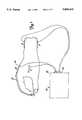
- FIG. 1shows a stimulator unit connected to a brace which is attached to a flexing portion of the body.
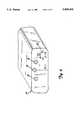
- FIG. 2is a perspective view of a stimulator unit having two output channels.
- FIG. 3is a perspective view of a stimulator unit having one output channel.
- FIG. 4is a front plan view of a stimulator unit having two non-isolated output channels.
- FIG. 5A-5Dillustrates a constant current pulse train and high and low cycles of current pulses.
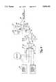
- FIG. 6is a block diagram of the compliance monitor and its interrelationship to the stimulator unit.
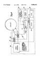
- FIG. 7is a block diagram of the compliance monitor showing the parts of the controller.
- FIG. 8is a schematic of the gating circuit in the controller.
- FIG. 9shows another embodiment of the controller.
- tissue treatment deviceis an electrotherapy unit 10 secured to a body portion 12.
- the electrotherapy unit 10comprises a stimulator unit 14 and at least two electrodes 16 (as shown in FIG. 1, the unit 10 has four electrodes 16).
- the stimulator unit 14will have at least one output channel 18.
- the unit 10has two output channels 18.
- a pair of electrodes 16is electrically connected to one output channel 18.
- Electrical currentis supplied to the body portion 12 through the electrodes 16 from the stimulator unit 14 via the output channel 18.
- the apparatus of the present inventionis located within the stimulator unit 14 such that it is able to monitor electrical stimulation flowing through the output channel 18.
- the stimulator unit 14may be, among others, a neuromuscular stimulator (“NMS”) unit, a transcutaneous electrical nerve stimulator (“TENS”) unit, a high voltage pulsed galvanic stimulator unit, an interferential stimulator unit, or a microcurrent stimulator unit.
- NMSneuromuscular stimulator
- TENStranscutaneous electrical nerve stimulator
- high voltage pulsed galvanic stimulator unitan interferential stimulator unit
- microcurrent stimulator unita microcurrent stimulator unit.
- the apparatus of the present inventionis designed to be used with any type of electrical stimulator unit 14. Although the present invention will be described in terms of sensing current, the present invention could be used to sense voltage or other physical value representative of unit output by a stimulator unit 14.
- FIG. 2shows a typical stimulator unit which has two isolated output channels 18. Furthermore, as shown in FIG. 2, the stimulator unit 14 may have an amplitude control 20, a frequency control 22, and a low battery indicator 24.
- FIGS. 3 and 4show a stimulator unit 14 having a single output channel 18 and a stimulator unit 14 having two non-isolated output channels 18 respectively.
- the non-isolated output channels 18share a common central electrode 19.
- the apparatus of the present inventionmay be used in these types of stimulator units 14 to determine the amount of time current is supplied to the user.
- a stimulator unit 14can provide a continuous train of current pulses 100 (see FIG. 5A).
- the stimulator unit 10monitors the current supplied and maintains the amount of current supplied through an output channel 18 at a constant level.
- the stimulator unit 10may also provide trains of interrupted current pulses 102.
- FIGS. 5B and 5Dshow a current pulse train 102 comprising a plurality of pulses 101 (see FIG. 5C).
- Pulse train 102is comprised of alternating high cycles 103 and low cycles 104.
- the high cycle 103 of pulse train 102has a ramp-up section 110, a peak current section 112, and a ramp-down section 114.
- Each high cycle 103 of pulse train 102comprises a plurality of pulses 101.
- the pulses 101vary in amplitude, and have a duration 105 and a pulse interval 106.
- Pulse duration 105 for most stimulatorsmay range from as low as 5 microseconds in HVPG stimulators to as high as 1000 microseconds in some muscle stimulators.
- the frequency for the pulses 101is between 1 pulses/second to 4000 pulses/second inclusive. However, for purposes of this invention, the frequency of this pulse 101 must not be less than the frequency of the high cycle 103.
- the high cycle 103 of a current pulse train 102current is delivered to the user.
- no currentis delivered to user. In certain treatment procedures the low cycle 104 could be as long as 50 seconds to one minute.
- stimulators 14 that provide pulsatile constant currentdeliver 0 to 100 milliamperes into patient loads of 100 to 1000 ohms.
- FIG. 6is a block diagram of a compliance monitor 30 located in a stimulator unit 14.
- the compliance monitor 30comprises a sensing element 32, a controller 34, and a timer 36.
- the stimulator unit 14houses a control reset switch 40 and a storage device 42, which are both operably connected to the controller 34.
- the stimulator unit 14has two isolated output channels 18 through which a current generator 46 supplies current to the patient.
- the stimulator unit 14also has a display device 44 for showing the amount of time the treatment has been received by the patient either on a cumulative basis or on a each discrete use basis.
- a sensing element 32is located at each of the two isolated output channels 18. Each sensing element 32 outputs a stimulation indication signal 48, which indicates whether current is flowing through the channel 18 that the sensing element 32 is monitoring. Each sensing element 32 is connected to the controller 34 so that the controller 34 is responsive to the stimulation indication signal 48 output by the sensing element 32. In some cases, this stimulation indication signal 48 may need to be amplified for use by the controller 34.
- each of the sensing elements 32determines whether current is flowing in the channel 18 that it is monitoring. Based on the state of current flow within its channel 18, each sensing element 32 outputs to the controller 34 a stimulation indication signal 48.
- This stimulation indication signal 48may need to be amplified if it is not strong enough for a controller 34 to use in determining whether current is flowing in the output channel 18.
- the controller 34determines whether to increment the timer 36.
- Each sensing element 32constantly monitors an output channel 18 to determine whether current is flowing through the channel 18 it is monitoring. When current is flowing through the channel 18, the timer is incremented. Once current stops flowing through the channel 18, the controller 34 will not increment the timer 36.
- the amount of time elapsed during the treatment periodmay be stored in the storage device 42. Also, the amount of time elapsed may be displayed on the display device 44. The patient may use the control reset switch 40 to reset the timer 36.
- the compliance monitor 30When a stimulator unit 14 provides a train of current pulses 102, in order to accurately measure the total treatment time, the compliance monitor 30 must not stop incrementing the timer 36 during the low cycle 104 of the pulse train 102. Thus, even though during a low cycle 104 of the pulse train 102 there is no current flowing in the output channel 18, the compliance monitor 30 should not stop incrementing the timer 36 during treatment. Thus, the compliance monitor 30 of the present invention must design for this condition.
- the treatment time measured by the apparatus of the present inventionincludes the high cycle 103 and the low cycle 104, this present invention provides design parameters which allows it to be modified to apply appropriate measurement protocols based on the selected treatment protocol.
- FIG. 7shows a block diagram of one embodiment of the compliance monitor 30 and its interrelationship to other parts of the stimulator unit 14.
- the controller 34comprises a level sensing amplifier and gating circuit 50 and a processor 52.
- the sensing element 32is electrically connected to the level sensing amplifier and gating circuit 50.
- the level sensing amplifier and gating circuit 50outputs a timer control signal, which allows the processor 52 to determine whether to increment the timer 36 or to not increment the timer 36.
- the processor 52is connected to the timer 36, the control reset switch 40, the storage device 42, the display device 44, and the current generator 46, which supplies pulsed current.
- FIG. 8is a circuit diagram of the sensing element 32 and the level sensing amplifier and gating circuit 50.
- the sensing element 32is formed by a transformer 60.
- the sensing element 32is a low-impedance, series sensing element.
- the transformer 60 used in the present inventioncomprises two isolated primary coil windings 62, 64 and a secondary coil winding 66.
- Each of the primary coil windings 62, 64has eight (8) turns.
- the inductance of each of the primary coil windings 62, 64is fifteen (15) microhenrys.
- the secondary coil winding 66has thirty-two turns. This secondary coil winding 66 is connected in parallel to capacitor C1. This secondary coil winding 66 is also connected to the negative input of the first comparator at node 67.
- the level sensing amplifier and gating circuit 50comprises a first comparator 70 having a positive terminal 72, a negative terminal 74 and an output 76, a second comparator 78 having a positive terminal 80, a negative terminal 82, and an output terminal 84, a time delay circuit 86, and a rectification circuit 88.
- the output 76 of the first comparator 70is connected to the rectification circuit 88.
- the rectification circuit 88is connected to the negative terminal 82 of the second comparator 78 and the delay circuit 86 at node 92.
- the output terminal 84 of the second comparator 78is connected to the processor 50.
- the positive terminals 72, 80is connected to one of nodes 94, 96 associated with one of first and second voltage dividing circuits 98, 99.
- the first voltage dividing circuit 98comprises resistor R1 and R2. Resistors R1 and R2 are connected to each other and the positive terminal 72 of the first comparator 70 at node 94.
- the other terminal of resistor R1is connected to the battery (or other power supply), and the other terminal of resistor R2 is connected to ground.
- the values of the secondary winding of the transformer and of resistors R1 and R2are selected so as to have a sense threshold of five percent or less of the maximum output of the stimulator.
- the first comparator 70Based on the threshold set by the values of the resistors R1 and R2 in the first voltage dividing circuit 98, which determines the sensitivity to current of the first comparator 70, and the current indication signal 48 output by the current sensing element 32, the first comparator 70 outputs a signal which indicates whether current is flowing in a channel 18.
- the second voltage dividing circuit 99comprises resistor R4 and R5. Resistors R4 and R5 are connected to each other and the positive terminal 80 of the second comparator at node 96. The other terminal of resistor R4 is connected to the battery (or other power supply), and the other terminal of resistor R5 is connected to ground.
- the valuesmust be chosen so that the controller 34 will increment the timer 36 during a low cycle 104 for a predetermined period of time, which defines the maximum amount of time a low cycle 104 can exist. However, if a particular treatment protocol requires a different time period measurement (e.g., not to include the entire low cycle), these values can be selected to allow for measurement of a treatment period in accordance with the treatment protocol.
- the time delay circuit 86comprises a capacitor C2 connected in parallel to a resistor R3. Values of C2 and R3 must be sufficiently large so that the voltage at the negative terminal 82 of the second comparator 78 remains below the voltage provided at the positive input of the second comparator by resistors R4 and R5 for a time in excess of the longest time period between output pulses of the stimulator. As described previously, for certain muscle stimulation treatments, the low cycles 104 of the pulse train 102 may be in excess of 30 or 40 seconds. Therefore, values for C2 and R3 may be as high as 10 microfarads and 10 megohms respectively. Thus, the time delay circuit 86 causes the output 84 of the second comparator 78, which is the timer control signal, to remain in a high state, thereby, providing accurate information regarding the amount of time the patient has been treated.
- the rectification circuit 88comprises a diode. This diode allows current to flow when the first comparator 70 outputs a low state through its output terminal 76. Otherwise, it prevents the flow of current to the first comparator 70.
- the stimulator unit 14is turned on and the current generator 46 provides a train of current pulses 102 through each of the output channels 18.
- the sensing element 32senses current in the output channel 18 and outputs a current indication signal 48 to the first comparator 70.
- This input to the negative terminal 72 of the first comparator 70causes the comparator's output to change from a high state to a low state. In the preferred embodiment, this change in output occurs during the ramp-up section 110 of the high cycle 103 of a pulse train 102.
- the values of resistors R1 and R2may be manipulated such that the threshold value allows the first comparator 70 output to change at a selected level during the ramp-up section 110 of the high cycle 103 of the pulse train 102.
- the diode 88allows current to flow to the first comparator 70.
- the output 76 of the first comparator 70is in a low state, capacitor C2 begins charging.
- the timer control signal 85 output by the second comparator 78 via its output 84 to the processor 52is in a high state. Based on the high state, the processor 52 increments the timer 36.
- the sensing element 32senses a drop in the amount of current in the output channel 18.
- the current indication signal 48 output by the current sensing element 32 to the negative input 72 of the first comparator 70causes it to output a high state.
- Capacitor C2begins to discharge through resistor R3.
- the voltage at the negative input of the second comparator 78remains below the voltage provided at the positive input 80 by resistors R4 and R5 for a time in excess of the longest time period between high cycles 103 of the pulse train 102 in of the stimulator 14.
- the timer control signal 85 output by the second comparator 78 through output 84remains in a high state, and the processor 52 continues to increment the timer 36.
- the processor 52will stop incrementing the digital timer 36.
- the processor 52displays the time value on an LCD display.
- the total time informationwould also be stored in a non-volatile memory (EPROM) using methods well known to those skilled in the art. Thus, a physician can accurately determine the cumulative time the patient had treatment.
- EPROMnon-volatile memory
- the sensing element 32may be the current sensor used in such units to maintain the constant current level.
- the output from the sensing element 32, which is used for feedback purposes in such units 14,may be by the controller 34 to determine the treatment period.
- FIG. 9shows a microprocessor based alternative embodiment.
- the controller 34is a processor 52.
- the processor 52has computer software to control sampling of stimulation indication signal 48 as well as interpretation of these sampled signals. As shown in FIG. 9, the detection of the low cycle may be achieved via software operative on the processor 52.
- the processor 52is responsive to the stimulation indication signal 48. Based on this signal 48, the processor 32 then determines whether current is flowing in a channel 18. If current is flowing in the channel 18, then the timer 36 is incremented. If current is not flowing in the channel 18, then the processor 52 continues to increment the timer 36 for a predetermined period of time. During that time, the processor 52 polls the sensing element 32 to determine whether the stimulation indication signal 48 indicates that current is flowing through the channel 18.
- the processor 52stops incrementing the timer 36. However, if current is detected, then the processor 52 continues to increment the timer 36.
- the processor 52can wait a predetermined period of time and again read the output from the sensing element 32 to determine if a high cycle 102 of the pulse train 102 has occurred.
- the computer software on the processor 52may be configured to sense selected treatment protocol waveform and to apply appropriate treatment period measurement protocol based on the treatment protocol waveform.
- the softwaremay, if necessary, apply a different treatment period measurement protocol based on the type of waveform output by a stimulator unit 14 (e.g., based on the waveforms output by a NMS unit, a TENS unit, a high voltage pulsed galvanic stimulator unit, an interferential stimulator unit, or a microcurrent stimulator unit).
- the transformermay be replaced with a simple small value resistor or parallel reversed diodes.
Landscapes
- Health & Medical Sciences (AREA)
- Life Sciences & Earth Sciences (AREA)
- Biophysics (AREA)
- Heart & Thoracic Surgery (AREA)
- Engineering & Computer Science (AREA)
- Biomedical Technology (AREA)
- Nuclear Medicine, Radiotherapy & Molecular Imaging (AREA)
- Radiology & Medical Imaging (AREA)
- Animal Behavior & Ethology (AREA)
- General Health & Medical Sciences (AREA)
- Public Health (AREA)
- Veterinary Medicine (AREA)
- Electrotherapy Devices (AREA)
Abstract
Description
Claims (28)
Priority Applications (1)
| Application Number | Priority Date | Filing Date | Title |
|---|---|---|---|
| US08/723,518US5800458A (en) | 1996-09-30 | 1996-09-30 | Compliance monitor for monitoring applied electrical stimulation |
Applications Claiming Priority (1)
| Application Number | Priority Date | Filing Date | Title |
|---|---|---|---|
| US08/723,518US5800458A (en) | 1996-09-30 | 1996-09-30 | Compliance monitor for monitoring applied electrical stimulation |
Publications (1)
| Publication Number | Publication Date |
|---|---|
| US5800458Atrue US5800458A (en) | 1998-09-01 |
Family
ID=24906610
Family Applications (1)
| Application Number | Title | Priority Date | Filing Date |
|---|---|---|---|
| US08/723,518Expired - LifetimeUS5800458A (en) | 1996-09-30 | 1996-09-30 | Compliance monitor for monitoring applied electrical stimulation |
Country Status (1)
| Country | Link |
|---|---|
| US (1) | US5800458A (en) |
Cited By (77)
| Publication number | Priority date | Publication date | Assignee | Title |
|---|---|---|---|---|
| US6064911A (en)* | 1997-08-08 | 2000-05-16 | Rehabilicare, Inc. | Device using both HVPC and NMS electrotherapy |
| USD434152S (en) | 1999-03-08 | 2000-11-21 | Stryker Instruments | Housing for electronics used in a patient therapy system |
| US6161095A (en)* | 1998-12-16 | 2000-12-12 | Health Hero Network, Inc. | Treatment regimen compliance and efficacy with feedback |
| US6334069B1 (en) | 1998-01-15 | 2001-12-25 | Regenesis Biomedical, Inc. | Pulsed electromagnetic energy treatment apparatus and method |
| US6442422B1 (en) | 1999-08-11 | 2002-08-27 | Ge Medical Systems Information Technologies, Inc. | Compliance monitoring apparatus and method |
| KR100357436B1 (en)* | 1999-02-08 | 2002-10-18 | 모승기 | Electrical clinical apparatus including safety circuit |
| US20030060847A1 (en)* | 2001-09-25 | 2003-03-27 | Petlan Jiri Joseph | Method and apparatus for treatment of living matter using pulsed radio frequency electromagnetic radiation |
| EP1181951A4 (en)* | 1999-05-17 | 2003-05-02 | Alexandr Alexandrovich Karasev | Electro-neuro-adaptive stimulator |
| US6564103B2 (en) | 2000-12-01 | 2003-05-13 | Visionquest Industries, Inc. | Electrical stimulator and method of use |
| USD481008S1 (en) | 2002-12-23 | 2003-10-21 | Vq Orthocare | Battery pack housing for electrical stimulator |
| USD482124S1 (en) | 2002-12-23 | 2003-11-11 | Vq Orthocare | Electrical neuromuscular stimulator |
| USD482453S1 (en) | 2002-12-26 | 2003-11-18 | Vq Orthocare | Modem housing for electrical stimulator |
| US20030233137A1 (en)* | 2002-06-13 | 2003-12-18 | Paul Edward L. | Transcutaneous electrical nerve stimulation device and method using microcurrent |
| US20040015212A1 (en)* | 2002-05-31 | 2004-01-22 | Empi, Corp. | Electrotherapy stimulation device having electrode peel off detection capabilities |
| US20040176820A1 (en)* | 2002-06-13 | 2004-09-09 | Paul Edward L. | Method and apparatus for performing microcurrent stimulation (MSC) therapy |
| USD498302S1 (en) | 2003-11-12 | 2004-11-09 | Vq Orthocare | Electrical stimulator |
| US20040236387A1 (en)* | 1998-06-03 | 2004-11-25 | Neurocontrol Corporation | Treatment of shoulder dysfunction using a percutaneous intramuscular stimulation system |
| US20050033405A1 (en)* | 2002-08-15 | 2005-02-10 | Gmp/Cardiac Care, Inc. | Rail stent-graft for repairing abdominal aortic aneurysm |
| US20050059153A1 (en)* | 2003-01-22 | 2005-03-17 | George Frank R. | Electromagnetic activation of gene expression and cell growth |
| US20050137649A1 (en)* | 2002-06-13 | 2005-06-23 | Paul Edward L.Jr. | Method and apparatus for performing microcurrent stimulation (MSC) therapy |
| US20050205566A1 (en)* | 2004-03-22 | 2005-09-22 | Solatronix, Inc. Incorporation | System and method of interferentially varying electromagnetic near field patterns |
| US20050278001A1 (en)* | 2004-06-15 | 2005-12-15 | Li Qin | Interferential and neuromuscular electrical stimulation system and apparatus |
| US20060009816A1 (en)* | 1998-06-03 | 2006-01-12 | Neurocontrol Corporation | Percutaneous intramuscular stimulation system |
| US20060052844A1 (en)* | 2004-09-02 | 2006-03-09 | Tom Newman | System and method for measuring modifying and reporting treatment compliance |
| EP1537893A3 (en)* | 1999-04-14 | 2006-03-29 | Transneuronix, Inc. | Programmable gastric stimulator apparatus |
| USD521933S1 (en) | 2003-12-05 | 2006-05-30 | Visionquest Industries, Inc. | Electrode lead wire connector |
| EP1294443A4 (en)* | 2000-06-16 | 2006-07-19 | Newmark Inc | Microcurrent therapy device |
| US20060217768A1 (en)* | 2005-01-28 | 2006-09-28 | Felix Buhlmann | Independent protection system for an electrical muscle stimulation apparatus and method of using same |
| US7167818B2 (en) | 1997-01-10 | 2007-01-23 | Health Hero Network, Inc. | Disease simulation system and method |
| US7223235B2 (en) | 1992-11-17 | 2007-05-29 | Health Hero Network, Inc. | System and method for monitoring blood pressure from a person |
| US7252636B2 (en) | 1997-03-28 | 2007-08-07 | Health Hero Network, Inc. | Networked system for interactive communication and remote monitoring of individuals |
| US7260480B1 (en) | 2003-04-07 | 2007-08-21 | Health Hero Network, Inc. | Method and system for integrating feedback loops in medical knowledge development and healthcare management |
| US7305348B1 (en) | 1996-02-20 | 2007-12-04 | Health Hero Network, Inc. | Aggregating and pooling health related information in a communication system with feedback |
| US7399276B1 (en) | 2003-05-08 | 2008-07-15 | Health Hero Network, Inc. | Remote health monitoring system |
| US20090157150A1 (en)* | 2007-11-26 | 2009-06-18 | Microtransponder Inc. | Implanted Driver with Resistive Charge Balancing |
| US20090157145A1 (en)* | 2007-11-26 | 2009-06-18 | Lawrence Cauller | Transfer Coil Architecture |
| US7555436B2 (en) | 1997-01-16 | 2009-06-30 | Health Hero Network, Inc. | Personalized display of health information |
| US20090198293A1 (en)* | 2003-12-19 | 2009-08-06 | Lawrence Cauller | Microtransponder Array for Implant |
| US7584108B2 (en) | 1996-12-23 | 2009-09-01 | Health Hero Network, Inc. | Network media access control system for encouraging patient compliance with a treatment plan |
| US7613590B2 (en) | 1992-11-17 | 2009-11-03 | Health Hero Network, Inc. | Modular microprocessor-based power tool system |
| US7624028B1 (en) | 1992-11-17 | 2009-11-24 | Health Hero Network, Inc. | Remote health monitoring and maintenance system |
| US20100004717A1 (en)* | 2008-07-02 | 2010-01-07 | Microtransponder Inc. | Timing Control for Paired Plasticity |
| US20100022908A1 (en)* | 2003-12-19 | 2010-01-28 | Board Of Regents, The University Of Texas System | System and Method for Interfacing Cellular Matter with a Machine |
| US20100036454A1 (en)* | 1998-06-03 | 2010-02-11 | Ndi Medical, Llc. | Systems and methods to place one or more leads in muscle for providing electrical stimulation to treat pain |
| US20100042180A1 (en)* | 2005-04-19 | 2010-02-18 | Compex Technologies, Inc | Electrical stimulation device and method for therapeutic treatment and pain management |
| US20100069994A1 (en)* | 2007-06-25 | 2010-03-18 | Microtransponder, Inc. | Methods of inducing paresthesia using wireless neurostimulation |
| US7689440B2 (en) | 1992-11-17 | 2010-03-30 | Health Hero Network, Inc. | Method and apparatus for remote health monitoring and providing health related information |
| US7765112B2 (en) | 1996-10-16 | 2010-07-27 | Health Hero Network, Inc. | Multiple patient monitoring system for proactive health management |
| US7814143B2 (en) | 1997-03-10 | 2010-10-12 | Health Hero Network, Inc. | System and method for modifying documents sent over a communications network |
| US7862506B2 (en) | 1994-05-23 | 2011-01-04 | Health Hero Network, Inc. | Diabetes management system |
| US20110178571A1 (en)* | 2007-04-19 | 2011-07-21 | Painless Medical Technologies, Ltd. | Method and Apparatus for Nerve and Muscle Stimulation and Pain Treatment |
| US8005690B2 (en) | 1998-09-25 | 2011-08-23 | Health Hero Network, Inc. | Dynamic modeling and scoring risk assessment |
| US8027809B2 (en) | 1992-11-17 | 2011-09-27 | Health Hero Network, Inc. | Home power management system |
| US8032399B2 (en) | 1994-04-26 | 2011-10-04 | Health Hero Network, Inc. | Treatment regimen compliance and efficacy with feedback |
| US8078431B2 (en) | 1992-11-17 | 2011-12-13 | Health Hero Network, Inc. | Home power management system |
| US8078407B1 (en) | 1997-03-28 | 2011-12-13 | Health Hero Network, Inc. | System and method for identifying disease-influencing genes |
| US8095340B2 (en) | 1992-11-17 | 2012-01-10 | Health Hero Network, Inc. | Home power management system |
| US8407063B2 (en) | 1992-11-17 | 2013-03-26 | Robert Bosch Healthcare Systems, Inc. | Multi-user remote health monitoring system with biometrics support |
| US8419636B2 (en) | 1992-11-17 | 2013-04-16 | Robert Bosch Healthcare Systems, Inc. | Method and system for improving adherence with a diet program or other medical regimen |
| WO2013069002A1 (en) | 2011-11-11 | 2013-05-16 | National University Of Ireland, Galway | A system for the management and prevention of venous pooling |
| US8457757B2 (en) | 2007-11-26 | 2013-06-04 | Micro Transponder, Inc. | Implantable transponder systems and methods |
| US8620438B1 (en) | 2007-02-13 | 2013-12-31 | Encore Medical Asset Corporation | Method and apparatus for applying neuromuscular electrical stimulation |
| CZ304552B6 (en)* | 2013-03-09 | 2014-07-02 | Jiří Kareš | Electric shock-preventing control device in instruments employing electricity for medical treatment and method of eliminating such electric shock |
| USD737328S1 (en) | 2013-06-17 | 2015-08-25 | Covidien Lp | Display screen with graphical user interface for venous refill detection |
| USD737327S1 (en) | 2013-06-17 | 2015-08-25 | Covidien Lp | Display screen with a transitional leak detection icon |
| USD737855S1 (en) | 2013-06-17 | 2015-09-01 | Covidien Lp | Display screen with a transitional venous refill detection icon |
| USD760728S1 (en) | 2013-06-17 | 2016-07-05 | Covidien Lp | Display screen with graphical user interface for patient use meter reset |
| USD774057S1 (en) | 2013-06-17 | 2016-12-13 | Covidien Lp | Display screen with a graphical user interface for compliance monitoring |
| US20170036009A1 (en)* | 2015-08-03 | 2017-02-09 | Clint Hughes | TENS with vibration and/or mechanical muscular manipulation |
| US20170196502A1 (en)* | 2010-09-30 | 2017-07-13 | Covidien Lp | Monitoring compliance using venous refill detection |
| US10076663B2 (en) | 2010-11-11 | 2018-09-18 | Spr Therapeutics, Inc. | Systems and methods for the treatment of pain through neural fiber stimulation |
| USD852970S1 (en)* | 2018-01-29 | 2019-07-02 | Charles A. Goodman | Sexual stimulation control box |
| US10722715B2 (en) | 2010-11-11 | 2020-07-28 | Spr Therapeutics, Inc. | Systems and methods for the treatment of pain through neural fiber stimulation |
| US10857361B2 (en) | 2010-11-11 | 2020-12-08 | Spr Therapeutics, Inc. | Systems and methods for the treatment of pain through neural fiber stimulation |
| US11331486B1 (en)* | 2019-08-01 | 2022-05-17 | Milly Ng | Method for reversing hearing loss |
| US11540973B2 (en) | 2016-10-21 | 2023-01-03 | Spr Therapeutics, Llc | Method and system of mechanical nerve stimulation for pain relief |
| US11623087B1 (en)* | 2019-08-01 | 2023-04-11 | Milly Ng | Method for non-surgical correction of joint deformity |
Citations (3)
| Publication number | Priority date | Publication date | Assignee | Title |
|---|---|---|---|---|
| US4509520A (en)* | 1982-02-22 | 1985-04-09 | Biolectron, Inc. | Electrical stimulating apparatus |
| US4553548A (en)* | 1983-08-19 | 1985-11-19 | Neuromedics, Inc. | Interrogator for muscle stimulator |
| US5233987A (en)* | 1992-07-09 | 1993-08-10 | Empi, Inc. | System and method for monitoring patient's compliance |
- 1996
- 1996-09-30USUS08/723,518patent/US5800458A/ennot_activeExpired - Lifetime
Patent Citations (3)
| Publication number | Priority date | Publication date | Assignee | Title |
|---|---|---|---|---|
| US4509520A (en)* | 1982-02-22 | 1985-04-09 | Biolectron, Inc. | Electrical stimulating apparatus |
| US4553548A (en)* | 1983-08-19 | 1985-11-19 | Neuromedics, Inc. | Interrogator for muscle stimulator |
| US5233987A (en)* | 1992-07-09 | 1993-08-10 | Empi, Inc. | System and method for monitoring patient's compliance |
Non-Patent Citations (1)
| Title |
|---|
| Declaration of David Kaysen (signed Mar. 2, 1998).* |
Cited By (174)
| Publication number | Priority date | Publication date | Assignee | Title |
|---|---|---|---|---|
| US8019618B2 (en) | 1992-11-17 | 2011-09-13 | Health Hero Network, Inc. | Report generation in a networked health-monitoring system |
| US8015030B2 (en) | 1992-11-17 | 2011-09-06 | Health Hero Network, Inc. | User-based health monitoring |
| US9215979B2 (en) | 1992-11-17 | 2015-12-22 | Robert Bosch Healthcare Systems, Inc. | Multi-user remote health monitoring system |
| US7223236B2 (en) | 1992-11-17 | 2007-05-29 | Health Hero Network, Inc. | System and method for monitoring user-related data from a person |
| US7264591B2 (en) | 1992-11-17 | 2007-09-04 | Health Hero Netowrk, Inc. | System and method for monitoring air flow from a person |
| US8617065B2 (en) | 1992-11-17 | 2013-12-31 | Robert Bosch Healthcare Systems, Inc. | Networked system for interactive communication and remote monitoring of individuals |
| US8489428B2 (en) | 1992-11-17 | 2013-07-16 | Robert Bosch Healthcare Systems, Inc. | Remote health monitoring and maintenance system |
| US8419636B2 (en) | 1992-11-17 | 2013-04-16 | Robert Bosch Healthcare Systems, Inc. | Method and system for improving adherence with a diet program or other medical regimen |
| US8407063B2 (en) | 1992-11-17 | 2013-03-26 | Robert Bosch Healthcare Systems, Inc. | Multi-user remote health monitoring system with biometrics support |
| US8260630B2 (en) | 1992-11-17 | 2012-09-04 | Health Hero Network, Inc. | Modular microprocessor-based appliance system |
| US8015025B2 (en) | 1992-11-17 | 2011-09-06 | Health Hero Network, Inc. | Method and apparatus for remote health monitoring and providing health related information |
| US8095340B2 (en) | 1992-11-17 | 2012-01-10 | Health Hero Network, Inc. | Home power management system |
| US8078431B2 (en) | 1992-11-17 | 2011-12-13 | Health Hero Network, Inc. | Home power management system |
| US7613590B2 (en) | 1992-11-17 | 2009-11-03 | Health Hero Network, Inc. | Modular microprocessor-based power tool system |
| US8027809B2 (en) | 1992-11-17 | 2011-09-27 | Health Hero Network, Inc. | Home power management system |
| US8024201B2 (en) | 1992-11-17 | 2011-09-20 | Health Hero Network, Inc. | Method and apparatus for remote health monitoring and providing health related information |
| US9477939B2 (en) | 1992-11-17 | 2016-10-25 | Robert Bosch Healthcare Systems, Inc. | Radio frequency based remote health monitoring |
| US7223235B2 (en) | 1992-11-17 | 2007-05-29 | Health Hero Network, Inc. | System and method for monitoring blood pressure from a person |
| US8249894B2 (en) | 1992-11-17 | 2012-08-21 | Robert Bosch Healthcare, Inc. | Networked remote patient monitoring with handheld devices |
| US7979284B2 (en) | 1992-11-17 | 2011-07-12 | Health Hero Network, Inc. | Interactive video based remote health monitoring system |
| US7624028B1 (en) | 1992-11-17 | 2009-11-24 | Health Hero Network, Inc. | Remote health monitoring and maintenance system |
| US7941327B2 (en) | 1992-11-17 | 2011-05-10 | Health Hero Network, Inc. | User monitoring |
| US7877276B2 (en) | 1992-11-17 | 2011-01-25 | Health Hero Network, Inc. | Messaging to remote patients in a networked health-monitoring system |
| US7689440B2 (en) | 1992-11-17 | 2010-03-30 | Health Hero Network, Inc. | Method and apparatus for remote health monitoring and providing health related information |
| US7761312B2 (en) | 1992-11-17 | 2010-07-20 | Health Hero Network, Inc. | Remote health monitoring and maintenance system |
| US7853455B2 (en) | 1992-11-17 | 2010-12-14 | Health Hero Network, Inc. | Remote health monitoring and maintenance system |
| US8032399B2 (en) | 1994-04-26 | 2011-10-04 | Health Hero Network, Inc. | Treatment regimen compliance and efficacy with feedback |
| US7862506B2 (en) | 1994-05-23 | 2011-01-04 | Health Hero Network, Inc. | Diabetes management system |
| US7867165B2 (en) | 1994-05-23 | 2011-01-11 | Health Hero Network, Inc. | System and method for monitoring a physiological condition |
| US7869852B2 (en) | 1994-05-23 | 2011-01-11 | Health Hero Network, Inc. | Diabetes management system |
| US7871376B2 (en) | 1994-05-23 | 2011-01-18 | Health Hero Network, Inc. | System and method for monitoring a physiological condition |
| US7972267B2 (en) | 1994-05-23 | 2011-07-05 | Health Hero Network, Inc. | Diabetes management system |
| US8616895B2 (en) | 1994-05-23 | 2013-12-31 | Robert Bosch Healthcare Systems, Inc. | System and method for monitoring a physiological condition |
| US8655259B2 (en) | 1994-05-23 | 2014-02-18 | Robert Bosch Healthcare Systems, Inc. | System and method for monitoring a physiological condition |
| US7258666B2 (en) | 1995-06-07 | 2007-08-21 | Health Hero Network, Inc. | System and methods for monitoring a patient's heart condition |
| US7684999B2 (en) | 1995-06-07 | 2010-03-23 | Health Hero Network, Inc. | User-based health monitoring |
| US7305348B1 (en) | 1996-02-20 | 2007-12-04 | Health Hero Network, Inc. | Aggregating and pooling health related information in a communication system with feedback |
| US7840420B2 (en) | 1996-10-16 | 2010-11-23 | Health Hero Network, Inc. | Multiple patient monitoring system for proactive health management |
| US7778845B2 (en) | 1996-10-16 | 2010-08-17 | Health Hero Network, Inc. | Multiple patient monitoring system for proactive health management |
| US7769605B2 (en) | 1996-10-16 | 2010-08-03 | Health Hero Network, Inc. | Multiple patient monitoring system for proactive health management |
| US7765112B2 (en) | 1996-10-16 | 2010-07-27 | Health Hero Network, Inc. | Multiple patient monitoring system for proactive health management |
| US7636667B2 (en) | 1996-12-23 | 2009-12-22 | Health Hero Networks, Inc. | Network media access control system for encouraging patient compliance with a treatment plan |
| US7590549B2 (en) | 1996-12-23 | 2009-09-15 | Health Hero Network, Inc. | Network media access control system for encouraging patient compliance with a treatment plan |
| US7584108B2 (en) | 1996-12-23 | 2009-09-01 | Health Hero Network, Inc. | Network media access control system for encouraging patient compliance with a treatment plan |
| US7643971B2 (en) | 1997-01-10 | 2010-01-05 | Health Hero Network, Inc. | Disease simulation system and method |
| US7167818B2 (en) | 1997-01-10 | 2007-01-23 | Health Hero Network, Inc. | Disease simulation system and method |
| US7392167B2 (en) | 1997-01-10 | 2008-06-24 | Health Hero Network, Inc. | Disease simulation system and method |
| US7555436B2 (en) | 1997-01-16 | 2009-06-30 | Health Hero Network, Inc. | Personalized display of health information |
| US7925522B2 (en) | 1997-01-16 | 2011-04-12 | Health Hero Network, Inc. | Personalized body image |
| US7613621B2 (en) | 1997-01-16 | 2009-11-03 | Health Hero Network, Inc. | Personalized body image |
| US7814143B2 (en) | 1997-03-10 | 2010-10-12 | Health Hero Network, Inc. | System and method for modifying documents sent over a communications network |
| US8078407B1 (en) | 1997-03-28 | 2011-12-13 | Health Hero Network, Inc. | System and method for identifying disease-influencing genes |
| US8608653B2 (en) | 1997-03-28 | 2013-12-17 | Robert Bosch Gmbh | Networked system for interactive communication and remote monitoring of individuals |
| US8990336B2 (en) | 1997-03-28 | 2015-03-24 | Robert Bosch Healthcare Systems, Inc. | Networked system for interactive communication and remote monitoring of individuals |
| US8870762B2 (en) | 1997-03-28 | 2014-10-28 | Robert Bosch Gmbh | Electronic data capture in clinical and pharmaceutical trials |
| US7987100B2 (en) | 1997-03-28 | 2011-07-26 | Health Hero Network, Inc. | Networked system for interactive communication and remote monitoring of individuals |
| US8353827B2 (en) | 1997-03-28 | 2013-01-15 | Robert Bosch Healthcare Systems, Inc. | Networked system for interactive communication and remote monitoring of individuals |
| US7730177B2 (en) | 1997-03-28 | 2010-06-01 | Health Hero Network, Inc. | Networked system for interactive communication and remote monitoring of individuals |
| US7921186B2 (en) | 1997-03-28 | 2011-04-05 | Health Hero Network, Inc. | Networked system for interactive communication and remote monitoring of individuals |
| US7707270B2 (en) | 1997-03-28 | 2010-04-27 | Health Hero Network, Inc. | Networked system for interactive communication and remote monitoring of individuals |
| US7587469B2 (en) | 1997-03-28 | 2009-09-08 | Health Hero Network, Inc. | Audio instructions for appliances |
| US7516192B2 (en) | 1997-03-28 | 2009-04-07 | Health Hero Network, Inc. | Networked system for interactive communication and remote monitoring of individuals |
| US7320030B2 (en) | 1997-03-28 | 2008-01-15 | Health Hero Network, Inc. | Remote health monitoring apparatus using scripted communications |
| US7734718B2 (en) | 1997-03-28 | 2010-06-08 | Health Hero Network, Inc. | Smart appliance functionality |
| US7533171B2 (en) | 1997-03-28 | 2009-05-12 | Health Hero Network, Inc. | Networked system for interactive communication and remote monitoring of individuals |
| US7252636B2 (en) | 1997-03-28 | 2007-08-07 | Health Hero Network, Inc. | Networked system for interactive communication and remote monitoring of individuals |
| US7310668B2 (en) | 1997-03-28 | 2007-12-18 | Health Hero Network, Inc. | Remotely monitoring an individual using scripted communications |
| US7822625B2 (en) | 1997-03-28 | 2010-10-26 | Health Hero Network, Inc. | Networked system for interactive communication and remote monitoring of individuals |
| US7870249B2 (en) | 1997-03-28 | 2011-01-11 | Health Hero Network, Inc. | Networked system for interactive communication and remote monitoring of individuals |
| US8140663B2 (en) | 1997-03-28 | 2012-03-20 | Health Hero Network, Inc. | Networked system for interactive communication and remote monitoring of individuals |
| US6064911A (en)* | 1997-08-08 | 2000-05-16 | Rehabilicare, Inc. | Device using both HVPC and NMS electrotherapy |
| US20110015698A1 (en)* | 1998-01-15 | 2011-01-20 | Regenesis Biomedical, Inc. | Pulsed electromagnetic energy treatment apparatus and method |
| US7024239B2 (en) | 1998-01-15 | 2006-04-04 | Regenesis Biomedical, Inc. | Pulsed electromagnetic energy treatment apparatus and method |
| US20020040233A1 (en)* | 1998-01-15 | 2002-04-04 | George Frank R. | Pulsed electromagnetic energy treatment apparatus and method |
| US6353763B1 (en) | 1998-01-15 | 2002-03-05 | Regenesis Biomedical, Inc. | Pulsed electromagnetic energy treatment apparatus and method |
| US6334069B1 (en) | 1998-01-15 | 2001-12-25 | Regenesis Biomedical, Inc. | Pulsed electromagnetic energy treatment apparatus and method |
| US20100036454A1 (en)* | 1998-06-03 | 2010-02-11 | Ndi Medical, Llc. | Systems and methods to place one or more leads in muscle for providing electrical stimulation to treat pain |
| US8626302B2 (en) | 1998-06-03 | 2014-01-07 | Spr Therapeutics, Llc | Systems and methods to place one or more leads in muscle for providing electrical stimulation to treat pain |
| US20040236387A1 (en)* | 1998-06-03 | 2004-11-25 | Neurocontrol Corporation | Treatment of shoulder dysfunction using a percutaneous intramuscular stimulation system |
| US20080177351A1 (en)* | 1998-06-03 | 2008-07-24 | Neurocontrol Corporation | Method of providing percutaneous intramuscular stimulation |
| US6845271B2 (en) | 1998-06-03 | 2005-01-18 | Neurocontrol Corporation | Treatment of shoulder dysfunction using a percutaneous intramuscular stimulation system |
| US20080065171A1 (en)* | 1998-06-03 | 2008-03-13 | Neurocontrol Corporation | Treatment of shoulder dysfunction using a percutaneous intramuscular stimulation system |
| US20060009816A1 (en)* | 1998-06-03 | 2006-01-12 | Neurocontrol Corporation | Percutaneous intramuscular stimulation system |
| US8249713B2 (en) | 1998-06-03 | 2012-08-21 | Spr Therapeutics, Llc | Treatment of shoulder dysfunction using a percutaneous intramuscular stimulation system |
| US8005690B2 (en) | 1998-09-25 | 2011-08-23 | Health Hero Network, Inc. | Dynamic modeling and scoring risk assessment |
| US8521546B2 (en) | 1998-09-25 | 2013-08-27 | Health Hero Network | Dynamic modeling and scoring risk assessment |
| US6161095A (en)* | 1998-12-16 | 2000-12-12 | Health Hero Network, Inc. | Treatment regimen compliance and efficacy with feedback |
| KR100357436B1 (en)* | 1999-02-08 | 2002-10-18 | 모승기 | Electrical clinical apparatus including safety circuit |
| USD434152S (en) | 1999-03-08 | 2000-11-21 | Stryker Instruments | Housing for electronics used in a patient therapy system |
| EP1537893A3 (en)* | 1999-04-14 | 2006-03-29 | Transneuronix, Inc. | Programmable gastric stimulator apparatus |
| EP1181951A4 (en)* | 1999-05-17 | 2003-05-02 | Alexandr Alexandrovich Karasev | Electro-neuro-adaptive stimulator |
| US6442422B1 (en) | 1999-08-11 | 2002-08-27 | Ge Medical Systems Information Technologies, Inc. | Compliance monitoring apparatus and method |
| EP1294443A4 (en)* | 2000-06-16 | 2006-07-19 | Newmark Inc | Microcurrent therapy device |
| US6564103B2 (en) | 2000-12-01 | 2003-05-13 | Visionquest Industries, Inc. | Electrical stimulator and method of use |
| US20030060847A1 (en)* | 2001-09-25 | 2003-03-27 | Petlan Jiri Joseph | Method and apparatus for treatment of living matter using pulsed radio frequency electromagnetic radiation |
| US6839589B2 (en)* | 2001-09-25 | 2005-01-04 | Jiri Joseph Petlan | Method and apparatus for treatment of living matter using pulsed radio frequency electromagnetic radiation |
| US20040015212A1 (en)* | 2002-05-31 | 2004-01-22 | Empi, Corp. | Electrotherapy stimulation device having electrode peel off detection capabilities |
| US20030233137A1 (en)* | 2002-06-13 | 2003-12-18 | Paul Edward L. | Transcutaneous electrical nerve stimulation device and method using microcurrent |
| US20050137649A1 (en)* | 2002-06-13 | 2005-06-23 | Paul Edward L.Jr. | Method and apparatus for performing microcurrent stimulation (MSC) therapy |
| US7187977B2 (en) | 2002-06-13 | 2007-03-06 | Atlantic Medical, Inc. | Transcutaneous electrical nerve stimulation device and method using microcurrent |
| US20040176820A1 (en)* | 2002-06-13 | 2004-09-09 | Paul Edward L. | Method and apparatus for performing microcurrent stimulation (MSC) therapy |
| WO2003105945A2 (en) | 2002-06-13 | 2003-12-24 | Paul Edward L Jr | Transcutaneous electrical nerve stimulation device and method using microcurrent |
| US20070016266A1 (en)* | 2002-06-13 | 2007-01-18 | Atlantic Medical, Inc. | Transcutaneous electrical nerve stimulation device and method using microcurrent |
| US7158834B2 (en) | 2002-06-13 | 2007-01-02 | Atlantic Medical, Inc. | Method and apparatus for performing microcurrent stimulation (MSC) therapy |
| US20050033405A1 (en)* | 2002-08-15 | 2005-02-10 | Gmp/Cardiac Care, Inc. | Rail stent-graft for repairing abdominal aortic aneurysm |
| USD482124S1 (en) | 2002-12-23 | 2003-11-11 | Vq Orthocare | Electrical neuromuscular stimulator |
| USD481008S1 (en) | 2002-12-23 | 2003-10-21 | Vq Orthocare | Battery pack housing for electrical stimulator |
| USD482453S1 (en) | 2002-12-26 | 2003-11-18 | Vq Orthocare | Modem housing for electrical stimulator |
| US20050059153A1 (en)* | 2003-01-22 | 2005-03-17 | George Frank R. | Electromagnetic activation of gene expression and cell growth |
| US7260480B1 (en) | 2003-04-07 | 2007-08-21 | Health Hero Network, Inc. | Method and system for integrating feedback loops in medical knowledge development and healthcare management |
| US8945009B2 (en) | 2003-05-08 | 2015-02-03 | Robert Bosch Heathcare Systems, Inc. | Remote health monitoring system |
| US7399276B1 (en) | 2003-05-08 | 2008-07-15 | Health Hero Network, Inc. | Remote health monitoring system |
| USD498302S1 (en) | 2003-11-12 | 2004-11-09 | Vq Orthocare | Electrical stimulator |
| USD521933S1 (en) | 2003-12-05 | 2006-05-30 | Visionquest Industries, Inc. | Electrode lead wire connector |
| US20090198293A1 (en)* | 2003-12-19 | 2009-08-06 | Lawrence Cauller | Microtransponder Array for Implant |
| US20100022908A1 (en)* | 2003-12-19 | 2010-01-28 | Board Of Regents, The University Of Texas System | System and Method for Interfacing Cellular Matter with a Machine |
| US20050205566A1 (en)* | 2004-03-22 | 2005-09-22 | Solatronix, Inc. Incorporation | System and method of interferentially varying electromagnetic near field patterns |
| US20050278001A1 (en)* | 2004-06-15 | 2005-12-15 | Li Qin | Interferential and neuromuscular electrical stimulation system and apparatus |
| US7613518B2 (en) | 2004-06-15 | 2009-11-03 | Encore Medical Asset Corporation | Interferential and neuromuscular electrical stimulation system and apparatus |
| US20060052844A1 (en)* | 2004-09-02 | 2006-03-09 | Tom Newman | System and method for measuring modifying and reporting treatment compliance |
| US8140165B2 (en) | 2005-01-28 | 2012-03-20 | Encore Medical Asset Corporation | Independent protection system for an electrical muscle stimulation apparatus and method of using same |
| US9808619B2 (en) | 2005-01-28 | 2017-11-07 | Encore Medical Asset Corporation | Independent protection system for an electrical muscle stimulation apparatus and method of using same |
| US20060217768A1 (en)* | 2005-01-28 | 2006-09-28 | Felix Buhlmann | Independent protection system for an electrical muscle stimulation apparatus and method of using same |
| US20100042180A1 (en)* | 2005-04-19 | 2010-02-18 | Compex Technologies, Inc | Electrical stimulation device and method for therapeutic treatment and pain management |
| US9669212B2 (en) | 2005-04-19 | 2017-06-06 | Djo, Llc | Electrical stimulation device and method for therapeutic treatment and pain management |
| US10328260B2 (en) | 2005-04-19 | 2019-06-25 | Djo, Llc | Electrical stimulation device and method for therapeutic treatment and pain management |
| US8958883B2 (en) | 2005-04-19 | 2015-02-17 | Pierre-Yves Mueller | Electrical stimulation device and method for therapeutic treatment and pain management |
| US9669211B2 (en) | 2007-02-13 | 2017-06-06 | Encore Medical Asset Corporation | Method and apparatus for applying neuromuscular electrical stimulation |
| US8620438B1 (en) | 2007-02-13 | 2013-12-31 | Encore Medical Asset Corporation | Method and apparatus for applying neuromuscular electrical stimulation |
| US9352151B2 (en) | 2007-02-13 | 2016-05-31 | Encore Medical Asset Corporation | Method and apparatus for applying neuromuscular electrical stimulation |
| US20110178571A1 (en)* | 2007-04-19 | 2011-07-21 | Painless Medical Technologies, Ltd. | Method and Apparatus for Nerve and Muscle Stimulation and Pain Treatment |
| US20100069994A1 (en)* | 2007-06-25 | 2010-03-18 | Microtransponder, Inc. | Methods of inducing paresthesia using wireless neurostimulation |
| US20090163889A1 (en)* | 2007-11-26 | 2009-06-25 | Microtransponder, Inc. | Biodelivery System for Microtransponder Array |
| US20090157142A1 (en)* | 2007-11-26 | 2009-06-18 | Microtransponder Inc. | Implanted Driver with Charge Balancing |
| US20090157145A1 (en)* | 2007-11-26 | 2009-06-18 | Lawrence Cauller | Transfer Coil Architecture |
| US8457757B2 (en) | 2007-11-26 | 2013-06-04 | Micro Transponder, Inc. | Implantable transponder systems and methods |
| US20090157150A1 (en)* | 2007-11-26 | 2009-06-18 | Microtransponder Inc. | Implanted Driver with Resistive Charge Balancing |
| US20100004705A1 (en)* | 2008-07-02 | 2010-01-07 | Microtransponder Inc. | Systems, Methods and Devices for Treating Tinnitus |
| US9345886B2 (en) | 2008-07-02 | 2016-05-24 | Microtransponder, Inc. | Timing control for paired plasticity |
| US8489185B2 (en) | 2008-07-02 | 2013-07-16 | The Board Of Regents, The University Of Texas System | Timing control for paired plasticity |
| US20100003656A1 (en)* | 2008-07-02 | 2010-01-07 | The Board Of Regents, The University Of Texas System | Systems, methods and devices for paired plasticity |
| US9089707B2 (en) | 2008-07-02 | 2015-07-28 | The Board Of Regents, The University Of Texas System | Systems, methods and devices for paired plasticity |
| US9272145B2 (en) | 2008-07-02 | 2016-03-01 | Microtransponder, Inc. | Timing control for paired plasticity |
| US9339654B2 (en) | 2008-07-02 | 2016-05-17 | Microtransponder, Inc. | Timing control for paired plasticity |
| US20100004717A1 (en)* | 2008-07-02 | 2010-01-07 | Microtransponder Inc. | Timing Control for Paired Plasticity |
| US8934967B2 (en) | 2008-07-02 | 2015-01-13 | The Board Of Regents, The University Of Texas System | Systems, methods and devices for treating tinnitus |
| US11116933B2 (en) | 2008-07-02 | 2021-09-14 | The Board Of Regents, The University Of Texas System | Systems, methods and devices for paired plasticity |
| US20170196502A1 (en)* | 2010-09-30 | 2017-07-13 | Covidien Lp | Monitoring compliance using venous refill detection |
| US10314531B2 (en)* | 2010-09-30 | 2019-06-11 | Kpr U.S., Llc | Monitoring compliance using venous refill detection |
| US20230079468A1 (en)* | 2010-09-30 | 2023-03-16 | Kpr U.S., Llc | Monitoring compliance using venous refill detection |
| US12274559B2 (en)* | 2010-09-30 | 2025-04-15 | Kpr U.S., Llc | Control unit for monitoring patient compliance with a compression therapy regimen |
| US11612746B2 (en) | 2010-11-11 | 2023-03-28 | Spr Therapeutics, Inc. | Systems and methods for the treatment of pain through neural fiber stimulation |
| US11344726B2 (en) | 2010-11-11 | 2022-05-31 | Spr Therapeutics, Inc. | Systems and methods for the treatment of pain through neural fiber stimulation |
| US10076663B2 (en) | 2010-11-11 | 2018-09-18 | Spr Therapeutics, Inc. | Systems and methods for the treatment of pain through neural fiber stimulation |
| US12194299B2 (en) | 2010-11-11 | 2025-01-14 | Spr Therapeutics, Inc. | Systems and methods for the treatment of pain through neural fiber stimulation |
| US12377270B2 (en) | 2010-11-11 | 2025-08-05 | Spr Therapeutics, Inc. | Systems and methods for the treatment of pain through neural fiber stimulation |
| US10722715B2 (en) | 2010-11-11 | 2020-07-28 | Spr Therapeutics, Inc. | Systems and methods for the treatment of pain through neural fiber stimulation |
| US10857361B2 (en) | 2010-11-11 | 2020-12-08 | Spr Therapeutics, Inc. | Systems and methods for the treatment of pain through neural fiber stimulation |
| US12076562B2 (en) | 2010-11-11 | 2024-09-03 | Spr Therapeutics, Inc. | Systems and methods for the treatment of pain through neural fiber stimulation |
| US12214198B2 (en) | 2010-11-11 | 2025-02-04 | Spr Therapeutics, Inc. | Systems and methods for the treatment of pain through neural fiber stimulation |
| WO2013069002A1 (en) | 2011-11-11 | 2013-05-16 | National University Of Ireland, Galway | A system for the management and prevention of venous pooling |
| CZ304552B6 (en)* | 2013-03-09 | 2014-07-02 | Jiří Kareš | Electric shock-preventing control device in instruments employing electricity for medical treatment and method of eliminating such electric shock |
| USD760728S1 (en) | 2013-06-17 | 2016-07-05 | Covidien Lp | Display screen with graphical user interface for patient use meter reset |
| USD737327S1 (en) | 2013-06-17 | 2015-08-25 | Covidien Lp | Display screen with a transitional leak detection icon |
| USD737855S1 (en) | 2013-06-17 | 2015-09-01 | Covidien Lp | Display screen with a transitional venous refill detection icon |
| USD737328S1 (en) | 2013-06-17 | 2015-08-25 | Covidien Lp | Display screen with graphical user interface for venous refill detection |
| USD774057S1 (en) | 2013-06-17 | 2016-12-13 | Covidien Lp | Display screen with a graphical user interface for compliance monitoring |
| US20170036009A1 (en)* | 2015-08-03 | 2017-02-09 | Clint Hughes | TENS with vibration and/or mechanical muscular manipulation |
| US11806300B2 (en) | 2016-10-21 | 2023-11-07 | Spr Therapeutics, Inc. | Method and system of mechanical nerve stimulation for pain relief |
| US11540973B2 (en) | 2016-10-21 | 2023-01-03 | Spr Therapeutics, Llc | Method and system of mechanical nerve stimulation for pain relief |
| US12310914B2 (en) | 2016-10-21 | 2025-05-27 | Spr Therapeutics, Inc. | Method and system of mechanical nerve stimulation for pain relief |
| USD852970S1 (en)* | 2018-01-29 | 2019-07-02 | Charles A. Goodman | Sexual stimulation control box |
| US11623087B1 (en)* | 2019-08-01 | 2023-04-11 | Milly Ng | Method for non-surgical correction of joint deformity |
| US11331486B1 (en)* | 2019-08-01 | 2022-05-17 | Milly Ng | Method for reversing hearing loss |
Similar Documents
| Publication | Publication Date | Title |
|---|---|---|
| US5800458A (en) | Compliance monitor for monitoring applied electrical stimulation | |
| US5233987A (en) | System and method for monitoring patient's compliance | |
| US7326181B2 (en) | Nervous tissue stimulation device and method | |
| CA1334597C (en) | Dental anesthesia apparatus | |
| CN110072451B (en) | Quantitative neuromuscular blockade sensing systems and methods | |
| US4151513A (en) | Apparatus for sensing and transmitting a pacemaker's stimulating pulse | |
| US4708142A (en) | Automatic cardiac capture threshold determination system and method | |
| US6620186B2 (en) | Method and system for medical lead impedance test | |
| EP0101513B1 (en) | Electrical stimulating apparatus | |
| US6442422B1 (en) | Compliance monitoring apparatus and method | |
| US9743878B2 (en) | Event-based lead impedance monitoring | |
| US8355783B2 (en) | Distributed lead functionality testing | |
| US4612934A (en) | Non-invasive multiprogrammable tissue stimulator | |
| EP1846094B1 (en) | System for performing neurophysiologic assessments during surgery | |
| US5755745A (en) | Portable muscle stimulator with removable data storage card | |
| US5910156A (en) | Non-physiologic sense detection for implantable medical devices | |
| US20050085743A1 (en) | Apparatus and method for intraoperative neural monitoring | |
| US3986496A (en) | Apparatus for sensing and transmitting a pacemaker's stimulating pulse | |
| US20020077572A1 (en) | Percutaneous intramuscular stimulation system | |
| CA1316987C (en) | Method and apparatus for measuring the lead current in a pacemaker | |
| EP3231365A1 (en) | Neurophysiologic monitoring system | |
| US7930028B2 (en) | Implantable cardiac device with a shock lead | |
| JPH09117453A (en) | Device and method for measurement of automatic current sensing threshold area | |
| EP1181951B1 (en) | Electro-neuro-adaptive stimulator | |
| EP1879653A1 (en) | System and method for capture management |
Legal Events
| Date | Code | Title | Description |
|---|---|---|---|
| AS | Assignment | Owner name:REHABILICARE, INC., MINNESOTA Free format text:ASSIGNMENT OF ASSIGNORS INTEREST;ASSIGNOR:WINGROVE, ROBERT C.;REEL/FRAME:008440/0206 Effective date:19970109 | |
| STCF | Information on status: patent grant | Free format text:PATENTED CASE | |
| AS | Assignment | Owner name:U.S. BANK NATIONAL ASSOCIATION, MINNESOTA Free format text:SECURITY INTEREST;ASSIGNOR:REHABILICARE INC.;REEL/FRAME:010133/0219 Effective date:19990714 | |
| FPAY | Fee payment | Year of fee payment:4 | |
| FPAY | Fee payment | Year of fee payment:8 | |
| AS | Assignment | Owner name:ENCORE MEDICAL ASSET CORPORATION,NEVADA Free format text:ASSIGNMENT OF ASSIGNORS INTEREST;ASSIGNOR:COMPEX TECHNOLOGIES, INC.;REEL/FRAME:017663/0173 Effective date:20060508 Owner name:ENCORE MEDICAL ASSET CORPORATION, NEVADA Free format text:ASSIGNMENT OF ASSIGNORS INTEREST;ASSIGNOR:COMPEX TECHNOLOGIES, INC.;REEL/FRAME:017663/0173 Effective date:20060508 | |
| AS | Assignment | Owner name:COMPEX TECHNOLOGIES, INC. AS SUCCESSOR IN INTEREST Free format text:RELEASE BY SECURED PARTY;ASSIGNOR:U.S. BANK NATIONAL ASSOCIATION;REEL/FRAME:018224/0963 Effective date:20060227 | |
| AS | Assignment | Owner name:BANK OF AMERICA, N.A., AS COLLATERAL AGENT, MASSAC Free format text:SECURITY AGREEMENT;ASSIGNORS:ENCORE MEDICAL HOLDINGS LLC;ENCORE MEDICAL FINANCE LLC;REEL/FRAME:018645/0158 Effective date:20061103 | |
| AS | Assignment | Owner name:ENCORE MEDICAL ASSET CORPORATION, NEVADA Free format text:RELEASE BY SECURED PARTY;ASSIGNOR:BANK OF AMERICA, N.A., AS COLLATERAL AGENT;REEL/FRAME:020196/0948 Effective date:20071116 | |
| AS | Assignment | Owner name:CREDIT SUISSE, AS COLLATERAL AGENT, NEW YORK Free format text:SECURITY AGREEMENT;ASSIGNOR:ENCORE MEDICAL ASSET CORPORATION;REEL/FRAME:020234/0433 Effective date:20071120 | |
| FEPP | Fee payment procedure | Free format text:PAT HOLDER NO LONGER CLAIMS SMALL ENTITY STATUS, ENTITY STATUS SET TO UNDISCOUNTED (ORIGINAL EVENT CODE: STOL); ENTITY STATUS OF PATENT OWNER: LARGE ENTITY | |
| FPAY | Fee payment | Year of fee payment:12 | |
| AS | Assignment | Owner name:THE BANK OF NEW YORK MELLON, AS SECOND LIEN AGENT, Free format text:SECURITY AGREEMENT;ASSIGNORS:DJO, LLC;EMPI, INC.;ENCORE MEDICAL ASSET CORPORATION;AND OTHERS;REEL/FRAME:028078/0320 Effective date:20120320 | |
| AS | Assignment | Owner name:WELLS FARGO BANK, NATIONAL ASSOCIATION, AS THE COL Free format text:SECURITY INTEREST;ASSIGNORS:DJO, LLC;EMPI, INC.;ENCORE MEDICAL ASSET CORPORATION;AND OTHERS;REEL/FRAME:035614/0001 Effective date:20150507 | |
| AS | Assignment | Owner name:EMPI, INC., MINNESOTA Free format text:RELEASE BY SECURED PARTY;ASSIGNOR:THE BANK OF NEW YORK MELLON, AS SECOND LIEN AGENT;REEL/FRAME:035706/0457 Effective date:20150507 Owner name:RIKCO INTERNATIONAL, LLC, WISCONSIN Free format text:RELEASE BY SECURED PARTY;ASSIGNOR:CREDIT SUISSE AG, AS COLLATERAL AGENT;REEL/FRAME:035706/0497 Effective date:20150507 Owner name:DJO, LLC, CALIFORNIA Free format text:RELEASE BY SECURED PARTY;ASSIGNOR:THE BANK OF NEW YORK MELLON, AS SECOND LIEN AGENT;REEL/FRAME:035706/0457 Effective date:20150507 Owner name:DJO, LLC, CALIFORNIA Free format text:RELEASE BY SECURED PARTY;ASSIGNOR:CREDIT SUISSE AG, AS COLLATERAL AGENT;REEL/FRAME:035706/0497 Effective date:20150507 Owner name:ENCORE MEDICAL ASSET CORPORATION, CALIFORNIA Free format text:RELEASE BY SECURED PARTY;ASSIGNOR:THE BANK OF NEW YORK MELLON, AS SECOND LIEN AGENT;REEL/FRAME:035706/0457 Effective date:20150507 Owner name:ENCORE MEDICAL ASSET CORPORATION, CALIFORNIA Free format text:RELEASE BY SECURED PARTY;ASSIGNOR:CREDIT SUISSE AG, AS COLLATERAL AGENT;REEL/FRAME:035706/0497 Effective date:20150507 Owner name:RIKCO INTERNATIONAL, LLC, WISCONSIN Free format text:RELEASE BY SECURED PARTY;ASSIGNOR:THE BANK OF NEW YORK MELLON, AS SECOND LIEN AGENT;REEL/FRAME:035706/0457 Effective date:20150507 Owner name:MACQUARIE US TRADING LLC, AS COLLATERAL AGENT, ILL Free format text:SECURITY AGREEMENT;ASSIGNORS:DJO, LLC;EMPI, INC.;ENCORE MEDICAL ASSET CORPORATION;AND OTHERS;REEL/FRAME:035707/0398 Effective date:20150507 Owner name:THE BANK OF NEW YORK MELLON, AS SECOND LIEN AGENT, Free format text:SECURITY AGREEMENT;ASSIGNORS:DJO, LLC;EMPI, INC.;ENCORE MEDICAL ASSET CORPORATION;AND OTHERS;REEL/FRAME:035707/0454 Effective date:20150507 Owner name:THE BANK OF NEW YORK MELLON, AS THIRD LIEN AGENT, Free format text:SECURITY AGREEMENT;ASSIGNORS:DJO, LLC;EMPI, INC.;ENCORE MEDICAL ASSET CORPORATION;AND OTHERS;REEL/FRAME:035707/0498 Effective date:20150507 | |
| AS | Assignment | Owner name:ENCORE MEDICAL ASSET CORPORATION, CALIFORNIA Free format text:RELEASE BY SECURED PARTY;ASSIGNOR:MACQUARIE US TRADING LLC AS COLLATERAL AGENT;REEL/FRAME:048655/0067 Effective date:20190222 Owner name:EMPI, INC., CALIFORNIA Free format text:RELEASE BY SECURED PARTY;ASSIGNOR:MACQUARIE US TRADING LLC AS COLLATERAL AGENT;REEL/FRAME:048655/0067 Effective date:20190222 Owner name:DJO, LLC, CALIFORNIA Free format text:RELEASE BY SECURED PARTY;ASSIGNOR:MACQUARIE US TRADING LLC AS COLLATERAL AGENT;REEL/FRAME:048655/0067 Effective date:20190222 Owner name:ENCORE MEDICAL, L.P., CALIFORNIA Free format text:RELEASE BY SECURED PARTY;ASSIGNOR:MACQUARIE US TRADING LLC AS COLLATERAL AGENT;REEL/FRAME:048655/0067 Effective date:20190222 Owner name:RIKCO INTERNATIONAL, LLC, CALIFORNIA Free format text:RELEASE BY SECURED PARTY;ASSIGNOR:MACQUARIE US TRADING LLC AS COLLATERAL AGENT;REEL/FRAME:048655/0067 Effective date:20190222 Owner name:DJO, LLC, CALIFORNIA Free format text:RELEASE BY SECURED PARTY;ASSIGNOR:THE BANK OF NEW YORK MELLON AS THIRD LIEN AGENT;REEL/FRAME:048608/0932 Effective date:20190222 Owner name:RIKCO INTERNATIONAL, LLC, CALIFORNIA Free format text:RELEASE BY SECURED PARTY;ASSIGNOR:THE BANK OF NEW YORK MELLON AS THIRD LIEN AGENT;REEL/FRAME:048608/0932 Effective date:20190222 Owner name:ENCORE MEDICAL ASSET CORPORATION, CALIFORNIA Free format text:RELEASE BY SECURED PARTY;ASSIGNOR:THE BANK OF NEW YORK MELLON AS THIRD LIEN AGENT;REEL/FRAME:048608/0932 Effective date:20190222 Owner name:EMPI, INC., CALIFORNIA Free format text:RELEASE BY SECURED PARTY;ASSIGNOR:THE BANK OF NEW YORK MELLON AS THIRD LIEN AGENT;REEL/FRAME:048608/0932 Effective date:20190222 Owner name:ENCORE MEDICAL, L.P., CALIFORNIA Free format text:RELEASE BY SECURED PARTY;ASSIGNOR:THE BANK OF NEW YORK MELLON AS THIRD LIEN AGENT;REEL/FRAME:048608/0932 Effective date:20190222 Owner name:ENCORE MEDICAL ASSET CORPORATION, CALIFORNIA Free format text:RELEASE BY SECURED PARTY;ASSIGNOR:THE BANK OF NEW YORK MELLON AS SECOND LIEN AGENT;REEL/FRAME:050129/0262 Effective date:20190222 Owner name:DJO, LLC, CALIFORNIA Free format text:RELEASE BY SECURED PARTY;ASSIGNOR:THE BANK OF NEW YORK MELLON AS SECOND LIEN AGENT;REEL/FRAME:050129/0262 Effective date:20190222 Owner name:EMPI, INC., CALIFORNIA Free format text:RELEASE BY SECURED PARTY;ASSIGNOR:THE BANK OF NEW YORK MELLON AS SECOND LIEN AGENT;REEL/FRAME:050129/0262 Effective date:20190222 Owner name:ENCORE MEDICAL, L.P., CALIFORNIA Free format text:RELEASE BY SECURED PARTY;ASSIGNOR:THE BANK OF NEW YORK MELLON AS SECOND LIEN AGENT;REEL/FRAME:050129/0262 Effective date:20190222 Owner name:RIKCO INTERNATIONAL, LLC, CALIFORNIA Free format text:RELEASE BY SECURED PARTY;ASSIGNOR:THE BANK OF NEW YORK MELLON AS SECOND LIEN AGENT;REEL/FRAME:050129/0262 Effective date:20190222 | |
| AS | Assignment | Owner name:ENCORE MEDICAL ASSET CORPORATION, CALIFORNIA Free format text:RELEASE BY SECURED PARTY;ASSIGNOR:WELLS FARGO BANK, NATIONAL ASSOCIATION AS COLLATERAL AGENT;REEL/FRAME:048672/0661 Effective date:20190222 Owner name:ENCORE MEDICAL, L.P., CALIFORNIA Free format text:RELEASE BY SECURED PARTY;ASSIGNOR:WELLS FARGO BANK, NATIONAL ASSOCIATION AS COLLATERAL AGENT;REEL/FRAME:048672/0661 Effective date:20190222 Owner name:EMPI, INC., CALIFORNIA Free format text:RELEASE BY SECURED PARTY;ASSIGNOR:WELLS FARGO BANK, NATIONAL ASSOCIATION AS COLLATERAL AGENT;REEL/FRAME:048672/0661 Effective date:20190222 Owner name:DJO, LLC, CALIFORNIA Free format text:RELEASE BY SECURED PARTY;ASSIGNOR:WELLS FARGO BANK, NATIONAL ASSOCIATION AS COLLATERAL AGENT;REEL/FRAME:048672/0661 Effective date:20190222 Owner name:RIKCO INTERNATIONAL, LLC, CALIFORNIA Free format text:RELEASE BY SECURED PARTY;ASSIGNOR:WELLS FARGO BANK, NATIONAL ASSOCIATION AS COLLATERAL AGENT;REEL/FRAME:048672/0661 Effective date:20190222 |