US5800433A - Spinal column retaining apparatus - Google Patents
Spinal column retaining apparatusDownload PDFInfo
- Publication number
- US5800433A US5800433AUS08/655,851US65585196AUS5800433AUS 5800433 AUS5800433 AUS 5800433AUS 65585196 AUS65585196 AUS 65585196AUS 5800433 AUS5800433 AUS 5800433A
- Authority
- US
- United States
- Prior art keywords
- fastener
- vertebra
- plate
- longitudinal axis
- lip
- Prior art date
- Legal status (The legal status is an assumption and is not a legal conclusion. Google has not performed a legal analysis and makes no representation as to the accuracy of the status listed.)
- Expired - Fee Related
Links
- 230000001154acute effectEffects0.000claimsabstractdescription10
- 210000000988bone and boneAnatomy0.000claimsdescription16
- 239000000463materialSubstances0.000description12
- 230000033001locomotionEffects0.000description10
- 238000003780insertionMethods0.000description3
- 230000037431insertionEffects0.000description3
- 229910001200FerrotitaniumInorganic materials0.000description2
- RTAQQCXQSZGOHL-UHFFFAOYSA-NTitaniumChemical compound[Ti]RTAQQCXQSZGOHL-UHFFFAOYSA-N0.000description2
- 239000000560biocompatible materialSubstances0.000description2
- 238000012986modificationMethods0.000description2
- 230000004048modificationEffects0.000description2
- 229910001220stainless steelInorganic materials0.000description2
- 239000010935stainless steelSubstances0.000description2
- 239000010936titaniumSubstances0.000description2
- 230000008468bone growthEffects0.000description1
- 230000002093peripheral effectEffects0.000description1
Images


Classifications
- A—HUMAN NECESSITIES
- A61—MEDICAL OR VETERINARY SCIENCE; HYGIENE
- A61F—FILTERS IMPLANTABLE INTO BLOOD VESSELS; PROSTHESES; DEVICES PROVIDING PATENCY TO, OR PREVENTING COLLAPSING OF, TUBULAR STRUCTURES OF THE BODY, e.g. STENTS; ORTHOPAEDIC, NURSING OR CONTRACEPTIVE DEVICES; FOMENTATION; TREATMENT OR PROTECTION OF EYES OR EARS; BANDAGES, DRESSINGS OR ABSORBENT PADS; FIRST-AID KITS
- A61F5/00—Orthopaedic methods or devices for non-surgical treatment of bones or joints; Nursing devices ; Anti-rape devices
- A61F5/01—Orthopaedic devices, e.g. long-term immobilising or pressure directing devices for treating broken or deformed bones such as splints, casts or braces
- A61F5/04—Devices for stretching or reducing fractured limbs; Devices for distractions; Splints
- A—HUMAN NECESSITIES
- A61—MEDICAL OR VETERINARY SCIENCE; HYGIENE
- A61B—DIAGNOSIS; SURGERY; IDENTIFICATION
- A61B17/00—Surgical instruments, devices or methods
- A61B17/56—Surgical instruments or methods for treatment of bones or joints; Devices specially adapted therefor
- A61B17/58—Surgical instruments or methods for treatment of bones or joints; Devices specially adapted therefor for osteosynthesis, e.g. bone plates, screws or setting implements
- A61B17/68—Internal fixation devices, including fasteners and spinal fixators, even if a part thereof projects from the skin
- A61B17/70—Spinal positioners or stabilisers, e.g. stabilisers comprising fluid filler in an implant
- A61B17/7059—Cortical plates
- A—HUMAN NECESSITIES
- A61—MEDICAL OR VETERINARY SCIENCE; HYGIENE
- A61B—DIAGNOSIS; SURGERY; IDENTIFICATION
- A61B17/00—Surgical instruments, devices or methods
- A61B17/56—Surgical instruments or methods for treatment of bones or joints; Devices specially adapted therefor
- A61B17/58—Surgical instruments or methods for treatment of bones or joints; Devices specially adapted therefor for osteosynthesis, e.g. bone plates, screws or setting implements
- A61B17/68—Internal fixation devices, including fasteners and spinal fixators, even if a part thereof projects from the skin
- A61B17/70—Spinal positioners or stabilisers, e.g. stabilisers comprising fluid filler in an implant
- A61B17/7001—Screws or hooks combined with longitudinal elements which do not contact vertebrae
- A61B17/7044—Screws or hooks combined with longitudinal elements which do not contact vertebrae also having plates, staples or washers bearing on the vertebrae
- A—HUMAN NECESSITIES
- A61—MEDICAL OR VETERINARY SCIENCE; HYGIENE
- A61B—DIAGNOSIS; SURGERY; IDENTIFICATION
- A61B17/00—Surgical instruments, devices or methods
- A61B17/56—Surgical instruments or methods for treatment of bones or joints; Devices specially adapted therefor
- A61B17/58—Surgical instruments or methods for treatment of bones or joints; Devices specially adapted therefor for osteosynthesis, e.g. bone plates, screws or setting implements
- A61B17/68—Internal fixation devices, including fasteners and spinal fixators, even if a part thereof projects from the skin
- A61B17/70—Spinal positioners or stabilisers, e.g. stabilisers comprising fluid filler in an implant
- A61B17/7001—Screws or hooks combined with longitudinal elements which do not contact vertebrae
- A61B17/7041—Screws or hooks combined with longitudinal elements which do not contact vertebrae with single longitudinal rod offset laterally from single row of screws or hooks
Definitions
- the present inventionrelates to an apparatus for use in retaining vertebrae of a spinal column in a desired spatial relationship.
- the present inventionrelates to an apparatus for use in retaining cervical vertebrae of a human spinal column in a desired spatial relationship.
- the present inventionis an apparatus for retaining first and second vertebrae of a spinal column in a desired spatial relationship.
- the apparatusincludes a longitudinal member positionable along the spinal column.
- a member connectable with the first vertebrahas first and second fastener openings and a portion engageable with the longitudinal member.
- a first fasteneris extendable through the first fastener opening in the member to connect the member with the first vertebra.
- the first fastenerhas a first end portion for attachment to the first vertebra and has a longitudinal axis.
- a second fasteneris extendable through the second fastener opening in the member to connect the member with the first vertebra.
- the second fastenerhas a first end portion for attachment to the first vertebra and has a longitudinal axis.
- the longitudinal axis of the first fastener and the longitudinal axis of the second fastenerconverge at an acute angle as viewed in the sagittal plane when the first and second fasteners connect the member with the first vertebra.
- the apparatusalso includes means for connecting the longitudinal member with the second vertebra.
- the member connectable with the first vertebrahas a body portion.
- the memberalso has a lip portion projecting in a first direction from the body portion of the member.
- the lip portion of the memberis engageable with a surface of the first vertebra facing toward the second vertebra.
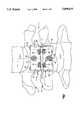
- FIG. 1is an elevational view of an apparatus constructed in accordance with the present invention for maintaining a desired spatial relationship between cervical vertebrae of a spinal column;
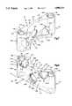
- FIG. 2is a view of the apparatus of FIG. 1, taken along the sagittal plane as indicated by line 2--2 of FIG. 1;
- FIG. 3is a sectional view taken generally along line 3--3 of FIG. 2;
- FIG. 4is a sectional view taken generally along line 4--4 of FIG. 2;
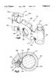
- FIG. 5is a perspective view of a first plate which forms a portion of the apparatus of FIG. 1;
- FIG. 6is another perspective view of the plate of FIG. 5;
- FIG. 7is a view similar to FIG. 5 of a second plate which forms a portion of the apparatus of FIG. 1;
- FIG. 8is another perspective view of the plate of FIG. 7;
- FIG. 9is a view similar to FIG. 1 of a modified embodiment of the invention.
- FIG. 10is a perspective view of a plate which is constructed in accordance with a second embodiment of the present invention.
- FIG. 11is an enlarged sectional view of a portion of the plate of FIG. 10 and showing a set screw and rod associated with the plate;
- FIG. 1illustrates an apparatus 10 for use in retaining bone portions such as cervical vertebrae V1 and V2 of a human spinal column C in a desired spatial relationship.
- the spinal column Chas an axis A which is a vertical axis of the human body.
- the apparatus 10includes a pair of surgically implantable rods 12 and 14 (FIGS. 1 and 2).
- the apparatus 10also includes first and second members or plates 30 and 32 which engage the rods 12 and 14; three fasteners 38, 40, and 42 for connecting the first plate with the first vertebra V1; and three fasteners 44, 46, and 48 for connecting the second plate with the second vertebra V2.
- the first rod 12(FIG. 1) is made of a suitable biocompatible material, such as titanium or stainless steel.
- the first rod 12has an elongate cylindrical configuration and has a circular cross section taken in a plane extending perpendicular to the longitudinal central axis of the first rod.
- the first rod 12has a smooth outer surface.
- a first end portion of the first rod 12is formed as a cap 50.
- the first rod 12also has a second end portion 52 opposite from the first end portion 50.
- the second rod 14is identical to the first rod 12.
- the second rod 14has a first end portion which is formed as a cap 54.
- the second rod 14also has a second end portion 56 opposite from the first end portion 54.
- the rods 12 and 14are bendable to a desired configuration to conform to a desired curvature of the spinal column C.
- the rods 12 and 14together have sufficient strength and rigidity to maintain the vertebrae V1 and V2 in a desired spatial relationship.
- the rods 12 and 14have a length which is sufficient to enable the rods to span at least the two vertebrae V1 and V2.
- the length of the rods 12 and 14will depend upon the condition to be corrected and the number of vertebrae to be held in a desired spatial relationship relative to each other by the apparatus 10. If more than two vertebrae are to be held in a desired spatial relationship relative to each other by the apparatus 10, the rods 12 and 14 would be longer and more than two plates, such as the plates 30 and 32, may be used.
- the first plate 30(FIGS. 5 and 6) is made of a suitable biocompatible material, such as titanium or stainless steel.
- the first plate 30includes a main body portion 60.
- the main body portion 60 of the first plate 30has a planar outer side surface 62 for facing anteriorly or away from the first vertebra V1.
- the first plate 30has an arcuate inner side surface 64 for facing posteriorly or toward the first vertebra V1.
- the inner side surface 64 of the first plate 30may engage the anterior surface of the first vertebra V1 when the first plate is connected with the first vertebra as described below.
- the main body portion 60 of the first plate 30has a central portion 66 which extends laterally between a first side portion 68 and a second side portion 70 of the first plate. Because the inner side surface 64 of the first plate 30 has an arcuate configuration, the central portion 66 of the first plate is relatively thin (as viewed in a direction from left to right in FIG. 3) as compared to the first side portion 68 and to the second side portion 70.
- the main body portion 60 of the first plate 30also has first and second end portions 72 and 74.
- the first end portion 72 of the first plate 30includes a planar first end surface 76 of the first plate 30.
- the second end portion 74includes a planar second end surface 78 of the first plate 30.
- the second end surface 78extends parallel to the first end surface 76.
- a first rod passage 80is formed in the first side portion 68 of the first plate 30.
- the first rod passage 80is an opening which extends between the first and second end surfaces 76 and 78 of the first plate 30 in a direction parallel to the planar outer side surface 62 of the first plate.
- the first rod passage 80is defined by a cylindrical surface 81 and tapered pilot surfaces 83 and 84 at opposite ends of the cylindrical surface 81.
- the diameter of the cylindrical surface 81is slightly greater than the diameter of the first rod 12, so that the first rod and the first plate 30 can be relatively movable.
- the second side portion 70 of the first plate 30is a mirror image of the first side portion 68.
- a second rod passage 82is formed in the second side portion 70 of the first plate 30.
- the second rod passage 82is an opening which extends between the first and second end surfaces 76 and 78 of the first plate 30 in a direction parallel to the planar outer side surface 62 of the first plate.
- the second rod passage 82extends parallel to the first rod passage 80.
- the second rod passage 82is defined by a cylindrical surface 85 and tapered pilot surfaces 86 and 87 at opposite ends of the cylindrical surface 85.
- the diameter of the second rod passage 82is the same as the diameter of the first rod passage 80.
- the diameter of the cylindrical surface 85is slightly greater than the diameter of the second rod 14, so that the second rod and the first plate 30 can be relatively movable.
- a circular first fastener opening 90extends through the central portion 66 of the first plate 30.
- the first fastener opening 90has an axis 92 (FIG. 2) which extends perpendicular to the plane of the outer side surface 62 of the first plate 30.
- the axis 92extends in a first direction as indicated by the arrow 94, that is, from right to left as viewed in FIG. 2, when the first plate 30 is mounted on the first vertebra V1.
- the first direction 94extends perpendicular to the axes of the rods 12 and 14.
- the first fastener opening 90is partially defined by a larger diameter cylindrical surface 96 (FIG. 6) which extends from the outer side surface 62 of the first plate 30 in a direction into the material of the central portion 66 of the first plate.
- the cylindrical surface 96is centered on the axis 92 of the first fastener opening 90.
- the first fastener opening 90is partially defined by a smaller diameter cylindrical surface 98 which extends from the inner side surface 64 of the first plate 30 in a direction into the material of the central portion 66 of the first plate to a location spaced radially inward from the surface 96.
- the cylindrical surface 98is centered on the axis 92 of the first fastener opening 90.
- An annular shoulder surface 100extends radially (relative to the axis 92) between the cylindrical surfaces 96 and 98.
- the shoulder surface 100 and the larger diameter cylindrical surface 96define a recess 102 in the outer side surface 62 of the first plate 30.
- the main body portion 60 of the first plate 30also includes a circular second fastener opening 110 formed at a location adjacent to, but spaced apart from, the first rod passage 80 in the first side portion 68 of the first plate.
- the second fastener opening 110extends through both the second end surface 78 of the first plate 30 and the outer side surface 62 of the first plate.
- the second fastener opening 110is partially defined by a larger diameter cylindrical surface 112 (FIG. 6) which extends from the outer side surface of the first plate 30 in a direction into the material of the first side portion 68 of the first plate.
- the cylindrical surface 112is centered on an axis 114 (FIG. 2) of the second fastener opening 110.
- the cylindrical surface 112is spaced apart from the first rod passage 80.
- the second fastener opening 110is partially defined by a smaller diameter cylindrical surface 116 (FIG. 6) which extends from the inner side surface 64 of the first plate 30 in a direction into the material of the first side portion 68 of the first plate, to a location spaced radially inward from the surface 112.
- the cylindrical surface 116is centered on the axis 114 of the second fastener opening 110.
- An annular shoulder surface 118extends radially (relative to the axis 114) between the cylindrical surfaces 112 and 116.
- the shoulder surface 118 and the larger diameter cylindrical surface 112define a recess 120 in the outer side surface 62 of the first plate 30.
- the axis 114 of the second fastener opening 110extends transverse to the axis 92 of the first fastener opening 90. Specifically, the axis 114 (FIG. 3) of the second fastener opening 110 converges with the axis 92 of the first fastener opening 90 as viewed in a transverse plane at right angles to the vertical axis A, as can be seen from FIG. 3. In the illustrated embodiment, the axis 114 converges at an angle of about 10° with the axis 92 as viewed in this transverse plane.
- the axis 114 of the second fastener opening 110also converges with the axis 92 of the first fastener opening 90 as viewed in the sagittal plane, as can be seen in FIG. 2.
- the axis 114converges at an angle of 45° with the axis 92 as viewed in the sagittal plane. It is contemplated that the angle of convergence as viewed in the sagittal plane could be in the range of from about 30° to about 60°.
- the main body portion 60 of the first plate 30also includes a circular third fastener opening 130 formed at a location adjacent to, but spaced apart from, the second rod passage 82 in the second side portion 70 of the first plate.
- the third fastener opening 130extends through both the second end surface 78 of the first plate 30 and the outer side surface 62 of the first plate.
- the third fastener opening 130is partially defined by a larger diameter cylindrical surface 132 (FIG. 6) which extends from the outer side surface 62 of the first plate 30 in a direction into the material of the second side portion 70 of the first plate.
- the cylindrical surface 132is centered on an axis 134 (FIG. 4) of the third fastener opening 130.
- the cylindrical surface 132is spaced apart from the second rod passage 82.
- the third fastener opening 130is partially defined by a smaller diameter cylindrical surface 136 (FIG. 6) which extends from the inner side surface 64 of the first plate 30 in a direction into the material of the second side portion 70 of the first plate, to a location spaced radially inward from the surface 32.
- the cylindrical surface 136is centered on the axis 134 of the third fastener opening 130.
- An annular shoulder surface 138extends radially (relative to the axis 134) between the cylindrical surfaces 132 and 136.
- the shoulder surface 138 and the larger diameter cylindrical surface 132define a recess 140 in the outer side surface 62 of the first plate 30.
- the axis 134 (FIG. 3) of the third fastener opening 130is coplanar with and extends parallel to the axis 114 of the second fastener opening 110.
- the axis 134 of the third fastener opening 130extends transverse to the axis 92 of the first fastener opening 90.
- the axis 134 of the third fastener opening 130converges with the axis 92 of the first fastener opening 90 as viewed in a transverse plane at right angles to the vertical axis A, as can be seen from FIG. 3.
- the axis 134converges with the axis 92 at an angle of 10° as viewed in this transverse plane.
- the axis 134 of the third fastener opening 130also converges with the axis 92 of the first fastener opening 90 as viewed in the sagittal plane, as can be seen from FIG. 2.
- the axis 134converges with the axis 92 at an angle of 45° as viewed in the sagittal plane. It is contemplated that this angle of convergence as viewed in the sagittal plane could be in the range of from about 30° to about 60°.
- the first plate 30includes a lip portion or lip 150 which is formed as one piece with the main body portion 60 of the first plate.
- the lip 150best seen in FIGS. 2 and 5, projects from the second end portion 74 of the main body portion 60 of the first plate 30.
- the lip 150projects in the first direction 94 (FIG. 2) when the first plate 30 is mounted on the first vertebra V1.
- the lip 150has a planar configuration as viewed in the first direction 94, for example, as seen in FIG. 2.
- the lip 150has an arcuate configuration, as can be seen in FIG. 5, when viewed in a direction parallel to the plane of the outer side surface 62 of the first plate 30.
- the arcuate configuration of the lip 150generally follows the arcuate configuration of the inner side surface 64 of the main body portion 60 of the first plate 30.
- the lip 150extends continuously between the first and second side portions 68 and 70 of the first plate 30.
- the lip 150may be discontinuous at one or more locations along the width of the plate 30.
- the lip 150has an outer end surface 152 (FIG. 2) which is formed as an extension of the second end surface 78 of the main body portion 60 of the first plate 30.
- An opposite inner end surface 154 (FIGS. 2 and 5) of the lip 150extends parallel to the outer end surface 152.
- the lip 150also has an inner side surface 156 which extends between the inner and outer end surfaces 154 and 152 of the lip 150.
- the second and third fastener openings 110 and 130extend partially through the lip 150.
- the second fastener opening 110as can be seen in FIG. 2, extends through the corner between, or intersection of, the lip 150 and the main body portion 60 of the first plate 30.
- the third fastener opening 130also extends through the corner between, or intersection of, the lip 150 and the main body portion 60 of the first plate 30.
- the second plate 32(FIG. 7) is generally similar in configuration to the first plate 30 (FIG. 5).
- the second plate 32 (FIG. 7)is configured, however, so that the head ends of fasteners received in certain fastener openings in the second plate are engageable with the rods 12 and 14 disposed in rod passages in the second plate. This engagement can block movement of the second plate 32 relative to the rods 12 and 14, in a manner described below.
- the second plate 32includes a main body portion 160 which has a planar outer side surface 162 for facing anteriorly or away from the vertebra V2.
- the main body portion 160also has an arcuate inner side surface 164 for facing posteriorly or toward the second vertebra V2.
- the inner side surface 164 of the second plate 32may engage the anterior surface of the second vertebra V2 when the second plate is connected with the second vertebra as described below.
- the main body portion 160has a central portion 166 which extends laterally between a first side portion 168 and a second side portion 170 of the second plate 32. Because the inner side surface 164 of the second plate 32 has an arcuate configuration, the central portion 166 of the second plate 32 is relatively thin (as viewed in a direction from left to right in FIG. 4) as compared to the first side portion 168 and to the second side portion 170.
- the main body portion 160 of the second plate 32also has first and second end portions 172 and 174.
- the first end portion 172 of the second plate 32includes a planar first end surface 176 of the second plate.
- the second end portion 174 of the second plate 32includes a planar second end surface 178 of the second plate.
- the second end surface 178extends parallel to the first end surface 176.
- a first rod passage 180is formed in the first side portion 168 of the second plate 32.
- the first rod passage 180is an opening which extends between the first and second end surfaces 176 and 178 in a direction parallel to the planar outer side surface 162 of the second plate 32.
- the first rod passage 180is defined by a cylindrical surface 181 and tapered pilot surfaces 183 and 184 at opposite ends of the cylindrical surface 181.
- the diameter of the cylindrical surface 181is slightly greater than the diameter of the first rod 12.
- a second rod passage 182is formed in the second side portion 170 of the second plate 32.
- the second rod passage 182is an opening which extends between the first and second end surfaces 176 and 178 in a direction parallel to the planar outer side surface 162 of the second plate 32.
- the second rod passage 182extends parallel to and has the same diameter as the second rod passage as first rod passage 180.
- the second rod passage 182is defined by a cylindrical surface 185 and tapered pilot surfaces 186 and 187 at opposite ends of the cylindrical surface 185.
- the diameter of the cylindrical surface 185is slightly greater than the diameter of the second rod 14.
- a circular first fastener opening 190extends through the central portion 166 of the second plate 32.
- the first fastener opening 190has an axis 192 (FIGS. 2 and 4) which extends perpendicular to the plane of the outer side surface 162 of the second plate 32.
- the axis 192extends in the first direction 94 when the second plate 32 is mounted on the second vertebra V2.
- the first fastener opening 190is partially defined by a larger diameter cylindrical surface 196 (FIG. 8) which extends from the outer side surface 162 of the second plate 32 in a direction into the material of the central portion 166 of the second plate.
- the cylindrical surface 196is centered on the axis 192 of the first fastener opening 190.
- the first fastener opening 190is partially defined by a smaller diameter cylindrical surface 198 which extends from the inner side surface 164 of the second plate 210 in a direction into the material of the central portion 166 of the second plate, to a location spaced radially inward from the surface 196.
- the cylindrical surface 198is centered on the axis 192 of the first fastener opening 190.
- An annular shoulder surface 200extends radially (relative to the axis 192) between the cylindrical surfaces 196 and 198.
- the shoulder surface 200 and the larger diameter cylindrical surface 196define a recess 202 in the outer side surface 162 of the second plate 32.
- the main body portion 160 of the second plate 32also includes a circular second fastener opening 210 formed at a location adjacent to and intersecting the first rod passage 180 in the first side portion 168 of the second plate.
- the second fastener opening 210extends through both the second end surface 178 of the second plate 32 and the outer side surface 162 of the second plate.
- the second fastener opening 210is partially defined by a larger diameter cylindrical surface 212 (FIG. 8) which extends from the outer side surface 262 of the second plate 32 in a direction into the material of the first side portion 168 of the second plate.
- the cylindrical surface 212is centered on an axis 214 (FIGS. 2 and 4) of the second fastener opening 210.
- the cylindrical surface 212intersects the cylindrical surface 181 which defines the first rod passage 180.
- the second fastener opening 210overlaps a portion of the first rod passage 180.
- the second fastener opening 210is partially defined by a smaller diameter cylindrical surface 216 which extends from the inner side surface 264 of the second plate 32 in a direction into the material of the first side portion 168 of the second plate, to a location spaced radially inward from the surface 212.
- the cylindrical surface 216is centered on the axis 214 of the second fastener opening 210.
- An annular shoulder surface 218extends radially (relative to the axis 214) between the cylindrical surfaces 212 and 216.
- the shoulder surface 218 and the larger diameter cylindrical surface 212define a recess 220 in the outer side surface 262 of the second plate 32.
- the axis 214 of the second fastener opening 210extends transverse to the axis 192 of the first fastener opening 190. Specifically, the axis 214 of the second fastener opening 210 converges with the axis 192 of the first fastener opening 190 as viewed in a transverse plane at right angles to the vertical axis A, as can be seen from FIG. 4. In the illustrated embodiment, the axis 214 converges with the axis 192 at angle of about 10° as viewed in this transverse plane.
- the axis 214 of the second fastener opening 210also converges with the axis 192 of the first fastener opening 190 as viewed in the sagittal plane, as can be seen in FIG. 2.
- the axis 214converges with the axis 192 at an angle of 45° as viewed in the sagittal plane. It is contemplated that this angle of convergence could be in the range of from about 30° to about 60° as viewed in the sagittal plane.
- the main body portion 160 of the second plate 32also includes a circular third fastener opening 230 formed at a location adjacent to and intersecting the second rod passage 182 in the second side portion 170 of the second plate.
- the third fastener opening 230extends through both the second end surface 178 of the second plate 32 and the outer side surface 162 of the second plate.
- the distance between the third fastener opening 230 in the second plate 32 and the second fastener opening 210 in the second plateis slightly less than the distance between the third fastener opening 130 in the first plate 30 and the second fastener opening 110 in the first plate.
- the third fastener opening 230is partially defined by a larger diameter cylindrical surface 232 (FIG. 8) which extends from the outer side surface 262 of the second plate 32 in a direction into the material of the second side portion 170 of the second plate.
- the cylindrical surface 232is centered on an axis 234 (FIG. 4) of the third fastener opening 230.
- the cylindrical surface 232intersects the cylindrical surface 185 which defines the second rod passage 182.
- the third fastener opening 230overlaps a portion of the second rod passage 182.
- the third fastener opening 230is partially defined by a smaller diameter cylindrical surface 236 (FIG. 8) which extends from the inner side surface 264 of the second plate 32 into the material of the second side portion 170 of the second plate to a location spaced radially inward from the surface 232.
- the cylindrical surface 236is centered on the axis 234 of the third fastener opening 230.
- An annular shoulder surface 238extends radially (relative to the axis 234) between the cylindrical surfaces 232 and 236.
- the shoulder surface 238 and the larger diameter cylindrical surface 232define a recess 240 in the outer side surface 162 of the second plate 32.
- the axis 234 of the third fastener opening 230is coplanar with and extends parallel to the axis 214 of the second fastener opening 210.
- the axis 234 of the third fastener opening 230extends transverse to the axis 192 of the first fastener opening 190.
- the axis 234 of the third fastener opening 230converges with the axis 192 of the first fastener opening 190 as viewed in a transverse plane at right angles to the vertical axis A, as can be seen from FIG. 4.
- the axis 234converges with the axis 192 at an angle of about 10° as viewed in this transverse plane.
- the axis 234 of the third fastener opening 230also converges with the axis 192 of the first fastener opening 190 as viewed in the sagittal plane, as can be seen from FIG. 2.
- the axis 234converges with the axis 192 at an angle of 45°. It is contemplated that this angle of convergence as viewed in the sagittal plane could be in the range of from about 30° to about 60°.
- the second plate 32includes a lip portion or lip 250 which is formed as one piece with the main body portion 160 of the second plate.
- the lip 250best seen in FIGS. 4 and 7, projects from the second end portion 174 of the main body portion 160 of the second plate 32.
- the lip 250projects in the first direction 94 (FIG. 2) when the second plate 32 is mounted on the second vertebra V2.
- the lip 250has a planar configuration as viewed in the first direction 94, for example, as seen in FIG. 2.
- the lip 250as viewed in a direction parallel to the plane of the outer side surface 162 of the second plate 32, has an arcuate configuration generally following the arcuate configuration of the inner side surface 164 of the main body portion 160 of the second plate 32.
- the lip 250extends continuously between the first and second side portions 168 and 170 of the second plate 32.
- the lip 250may be discontinuous at one or more locations along the width of the second plate 32.
- the lip 250has an outer end surface 252 (FIG. 2) which is formed as an extension of the second end surface 178 of the main body portion 160 of the second plate 32.
- An opposite inner end surface 254 (FIGS. 2 and 8) of the lip 250extends parallel to the outer side surface 252.
- the lip 250also has an inner side surface 256 which extends between the inner and outer end surfaces 252 and 254 of the lip 250.
- the second and third fastener openings 210 and 230extend partially through the lip 250.
- the second fastener opening 210, as well as the third fastener opening 230extend through the corner between, or intersection of, the lip 250 and the main body portion 160 of the second plate 32.
- the fasteners 38, 40, 42, 44, 46, and 48which connect the first plate 30 with the first vertebra V1 and the second plate 32 with the second vertebra V2, are identical to each other. Because the fasteners 38-48 are identical, only the fastener 40 is described herein in detail.
- the fastener 40(FIG. 3) includes a sleeve 300 and an expander 310.
- the sleeve 300has a hollow, elongate shank portion 302 centered on a longitudinal central axis 304 of the fastener 40.
- the shank portion 302defines a cylindrical central opening 308 in the sleeve 300.
- a coarse external helical thread convolution 306is formed on the outer peripheral surface of the shank portion 302 of the sleeve 300.
- the shank portion 302 of the sleeve 300is radially and axially slotted so that the shank portion is expandable radially.
- a series of projectionsare formed on the inner surface of the sleeve 300 for engagement by the expander 310 to expand the shank portion 302 of the sleeve in a manner described below.
- a head end portion 314 of the sleeve 300has a cylindrical outer side surface 316.
- An annular lip or rim 318extends around the head end portion 314 of the sleeve 300 and projects radially outward from the outer side surface 316.
- the head end portion 314 of the sleeve 300has a conical inner side surface 320 and a conical inner side surface 322.
- the conical inner side surface 322merges with an internal thread convolution 324 formed on the sleeve 300.
- the head end portion 314 of the sleeve 300is radially and axially slotted to define four segments 326 of the head end portion.
- the four segments 326are movable radially relative to each other and to the axis 304 of the fastener 40 so that the head end portion 314 of the sleeve 300 is expandable radially.
- the expander 310has a head end portion 340 and a shank portion 342.
- An inner end 344 of the shank portion 342 of the expander 310is slightly larger in diameter than the cylindrical central opening 308 in the sleeve 300.
- the head end portion 340 of the expander 310has an X-shaped driver slot 346 for receiving a driving tool for rotating the expander relative to the sleeve 300.
- the head end portion 340has a conical outer side surface 348 and a conical outer side surface 350.
- the conical outer side surface 350 on the head end portion 340 of the expander 310has a different angle of taper than does the conical inner side surface 322 on the head end portion 314 of the sleeve 300.
- the conical outer side surface 350 on the head end portion 340 of the expander 310merges with an external thread convolution 352 formed on the expander 310.
- the external thread convolution 352 on the expander 310screws into the internal thread convolution 324 on the sleeve 300.
- the rods 12 and 14are first assembled with the plates 30 and 32. Specifically, the first rod 12 is inserted through the first rod passage 80 in the first plate 30 and through the first rod passage 180 in the second plate 32. One of the tapered pilot surfaces 83 and 84 on the first plate 30, and one of the tapered pilot surfaces 183 and 184 on the second plate 32, guide insertion of the first rod 12. The second rod 12 is inserted through the second rod passage 82 in the first plate 30 and through the second rod passage 182 in the second plate 32. One of the tapered pilot surfaces 86 and 87 on the first plate 30, and one of the tapered pilot surfaces 186 and 187 on the second plate 32, guide insertion of the second rod 14.
- the assembly of the rods 12 and 14 and the plates 30 and 32is then positioned over the exposed anterior surface of the spinal column C.
- the first plate 30(FIG. 2) is positioned adjacent to the first vertebra V1 so that the first end surface 154 on the lip 150 of the first plate engages a lower surface 360 on the first vertebra V1.
- the lower surface 360 on the first vertebra V1faces toward the second vertebra V2.
- the second plate 32is positioned adjacent to the second vertebra V2 so that the first end surface 254 on the lip 250 of the second plate engages an upper surface 362 on the second vertebra V2.
- the upper surface 362 on the second vertebra V2faces toward the first vertebra V1.
- a suitable drill guide and drill(not shown) are used to drill fastener openings in the first vertebra V1 and in the second vertebra V2.
- the fasteners 38, 40 and 42are inserted to connect the first plate 30 with the first vertebra.
- the insertion and securing of the fastener 40, although not necessarily performed first,will be described as exemplary.
- the sleeve 300 of the fastener 40is inserted through the second fastener opening 110 in the first plate 30.
- the sleeve 300 of the fastener 40is threaded into the drilled opening in the vertebra V1 in a known manner (not shown) to fix the sleeve in position in the vertebra V1.
- the unexpanded head portion 314 of the sleeve 300is disposed in the recess 120 in the first plate 30.
- the expander 310 of the fastener 40is then inserted into the sleeve 300.
- the externally threaded portion 352 of the expander 310is screwed into the internal threads 324 on the sleeve 300.
- the inner end portion 344 of the expander 310causes the shank portion 302 of the sleeve to expand radially outward, helping to lock the sleeve in place in the vertebra V1.
- the head portion 340 of the expander 310engages the head portion 314 of the sleeve 300.
- the head portion 340 of the expander 310wedges the locking segments 326 on the sleeve 300 radially outward into engagement with the first plate 30 to rigidly lock the fastener 40 in position relative to the first plate.
- the head of the fastener 40is adjacent to the lip 150.
- the remaining fasteners 38 and 42 for the first plate 30are similarly secured to the vertebra V1 and are rigidly locked to the first plate.
- the heads of the fasteners 38 and 42are adjacent to the lip 150.
- the first plate 30is securely connected with the first vertebra V1.
- the fasteners 44, 46 and 48are similarly used to connect the second vertebra V2 and the second plate 32.
- the heads of the fasteners 44, 46, and 48are adjacent to the lip 250.
- the fasteners 44, 46 and 48are rigidly locked to the plate 32 and the plate 32 is securely connected with the second vertebra V2.
- the fastener 40(as well as the fastener 42, not shown in FIG. 2) extends at an angle (upward as viewed in FIG. 2) to the lip 150. Accordingly, when the fasteners 40 and 42 are tightened into the first vertebra V1, the fasteners tend to draw the lip 150 of the first plate 30 tightly against the surface 360 of the vertebra, that is, in an upward direction as viewed in FIG. 2. At the same time, the fasteners 40 and 42, as well as the fastener 38, tend to draw the main body portion 60 of the first plate 30 tightly against the anterior surface of the first vertebra V1, that is, in a direction to the left as viewed in FIG. 2. Accordingly, it can be seen that tightening the fasteners 38, 40 and 42 tends to draw the first plate 30 in two directions against the first vertebra V1.
- the first fastener 38has a longitudinal central axis which is coincident with the axis 92 of the first fastener opening 90 when the first fastener 38 is disposed in the first fastener opening 90 in the first plate 30.
- the longitudinal central axis 304 of the second fastener 40is coincident with the axis 114 of the second fastener opening 110.
- the axis 92 of the first fastener opening 90 and the axis 114 of the second fastener opening 110converge at an acute angle as viewed in the sagittal plane (FIG. 2). Therefore, the longitudinal axis of the first fastener 38 and the longitudinal axis 304 of the second fastener 40 converge at an acute angle as viewed in the sagittal plane (FIG. 2) when the first and second fasteners 38 and 40 connect the first plate 30 with the first vertebra V1.
- the axis of the first fastener 38 and the axis 304 of the second fastener 40converge at an angle of about 45° as viewed in the sagittal plane. It is contemplated that this angle of convergence in the sagittal plane could be in the range of from about 30° to about 60°.
- the longitudinal central axis of the third fastener 42is coincident with the axis 134 of the third fastener opening 130.
- the axis 92 of the first fastener opening 90 and the axis 134 of the third fastener opening 110converge at an acute angle as viewed in the sagittal plane (FIG. 2). Therefore, the longitudinal axis of the first fastener 38 and the longitudinal axis of the third fastener 42 converge at an acute angle as viewed in the sagittal plane (FIG. 2) when the first and third fasteners 38 and 42 connect the first plate 30 with the first vertebra V1.
- the axis of the first fastener 38 and the axis of the third fastener 42converge at an angle of about 45° as viewed in the sagittal plane. It is contemplated that this angle of convergence in the sagittal plane could be in the range of from about 30° to about 60°.
- the second plate 32is, in a similar manner, secured in position relative to the second vertebra V2. Tightening the fasteners 44, 46 and 48 tends to draw the second plate 32 in two directions against the second vertebra V2.
- the axis of the first fastener 44 and the axis of the second fastener 46converge at an acute angle as viewed in the sagittal plane (FIG. 2).
- the axis of the first fastener 44 and the axis of the third fastener 48converge at an acute angle as viewed in the sagittal plane (FIG. 2).
- these axesconverge at an angle of about 45° as viewed in the sagittal plane. It is contemplated that this angle of convergence in the sagittal plane could be in the range of from about 30° to about 60°.
- the outer fasteners 46 and 48secure the second plate and the second vertebra.
- the fasteners 46 and 48also serve to interlock the second plate 32 with the rods 12 and 14. This is because the locking segments 326 on the sleeves 300 of the fasteners 46 and 48 (FIG. 4) move radially outward into engagement with the rods 12 and 14, respectively, when each fastener's expander is fully screwed into the fastener's sleeve.
- the engagement between the fasteners 46 and 48 and the rods 12 and 14blocks movement of the fasteners 46 and 48 relative to the rods.
- the first plate 30,in contrast, is movable relative to the rods 12 and 14, because the second and third fastener openings 110 and 130 are spaced apart from the rod passages 80 and 82. Therefore, the first plate 30 is movable relative to the second plate 32.
- the first vertebra V1is movable vertically downward relative to the second vertebra V2.
- This relative movementallows for the maintaining of a load on bone graft placed between the vertebrae V1 and V2. If the first plate 30 were not movable vertically downward relative to the second plate 32, then the distance between the vertebrae V1 and V2 would be fixed. If bone graft were placed between the vertebrae V1 and V2 and the bone graft resorbed sufficiently, the bone graft could possibly shrink out of engagement with one or both of the vertebrae V1 and V2.
- Allowing relative movement of the plates 30 and 32can help to maintain a desired load on bone graft placed between the vertebrae V1 and V2 and maintains the vertebrae in contact with the bone graft to facilitate bone growth.
- the lips 150 and 250 on the plates 30 and 32are, preferably, configured so that the lips do not contact bone graft placed between the vertebrae.
- FIG. 9The upper plate 32 (FIG. 9) is fixed in position relative to the vertebra V1 and to the rods 12 and 14.
- the lower plate 32(FIG. 9) is fixed in position relative to the vertebra V2 and to the rods 12 and 14. Accordingly, the apparatus 10 (FIG. 9) blocks relative movement between the vertebrae V1 and V2.
- FIGS. 10 and 11illustrate a plate 30a which is constructed in accordance with a second embodiment of the present invention.
- the plate 30acan be substituted, in the apparatus 10, for the plate 30.
- the plate 30ais generally similar to the plate 30 (FIGS. 5 and 6), and similar reference numerals are used to designate similar parts, with the suffix "a" added in FIGS. 10 and 11 for clarity.
- a pair of set screws 370are provided for engaging the rods 12 and 14 to block movement of the plate, and thereby its associated bone portion, relative to the rods.
- the outer side surface 62a of the plate 30ais recessed at 372 adjacent to the second rod passage 82a.
- a seat 374extends inwardly from the recess 372 to a threaded opening 376.
- An inner end portion 378 of the opening 376intersects with the second rod passage 82a.
- a second threaded opening 380intersects the first rod passage 80a.
- fastenerssuch as the fasteners 38-42 are inserted through fastener openings 90a, 110a, and 130a in the plate 30a, to secure the plate to its associated bone portion.
- the head end portions of the fasteners for the plate 30ado not engage the rods 12 and 14, and do not clamp the rods against the plate 30a.
- a set screw 370is threaded into the opening 376.
- An inner end portion 382 of the set screw 370engages the cylindrical outer surface of the second rod 14.
- the engagement of the set screw 370 with the second rod 14clamps the rod against the second side portion 70a of the plate 30a.
- Another set screw 370is threaded into the opening 380 to engage the first rod 12 and clamp the first rod against the first side portion 68a of the plate 30a.
- the set screws 370, the rods 12 and 14, and the plate 30aare interlocked.
- the plate 30ais movable relative to (along the length of) the rods 12 and 14. Because the plate 30a is fixed to its associated bone portion, then the bone portion also is movable relative to the rods 12 and 14.
- a portion of the lip 150ais removed at the location of the fastener openings 110a and 130a, to provide better visibility.
- Thisprovides two lip segments 151 and 153 at the side portions 68a and 70a, respectively, of the plate 30a.
- the lip segments 151 and 153are spaced apart on opposite sides of the longitudinal axis, or centerline, of the plate 30a.
- a portion of the lip 150aalso is removed at the lateral center of the plate 30a, and a notch 384 is provided in the plate 30a, again to increase visibility.
Landscapes
- Health & Medical Sciences (AREA)
- Orthopedic Medicine & Surgery (AREA)
- Life Sciences & Earth Sciences (AREA)
- Neurology (AREA)
- Surgery (AREA)
- General Health & Medical Sciences (AREA)
- Veterinary Medicine (AREA)
- Engineering & Computer Science (AREA)
- Biomedical Technology (AREA)
- Heart & Thoracic Surgery (AREA)
- Public Health (AREA)
- Animal Behavior & Ethology (AREA)
- Molecular Biology (AREA)
- Medical Informatics (AREA)
- Nuclear Medicine, Radiotherapy & Molecular Imaging (AREA)
- Nursing (AREA)
- Vascular Medicine (AREA)
- Surgical Instruments (AREA)
- Prostheses (AREA)
- Medicines Containing Plant Substances (AREA)
- Investigating Or Analysing Biological Materials (AREA)
- Pharmaceuticals Containing Other Organic And Inorganic Compounds (AREA)
- Massaging Devices (AREA)
Abstract
Description
Claims (12)
Priority Applications (12)
| Application Number | Priority Date | Filing Date | Title |
|---|---|---|---|
| US08/655,851US5800433A (en) | 1996-05-31 | 1996-05-31 | Spinal column retaining apparatus |
| CA002203716ACA2203716C (en) | 1996-05-31 | 1997-04-25 | Spinal column retaining apparatus |
| EP97106886AEP0809971B1 (en) | 1996-05-31 | 1997-04-25 | Spinal column retaining system |
| ES97106886TES2196209T3 (en) | 1996-05-31 | 1997-04-25 | SPINAL COLUMN RETENTION SYSTEM. |
| DE69720591TDE69720591T2 (en) | 1996-05-31 | 1997-04-25 | Spine retention system |
| AT97106886TATE236581T1 (en) | 1996-05-31 | 1997-04-25 | SYSTEM FOR HOLDING THE SPINE |
| AU19151/97AAU695138B2 (en) | 1996-05-31 | 1997-04-29 | Spinal column retaining apparatus |
| JP12997097AJP3302611B2 (en) | 1996-05-31 | 1997-05-20 | Device for holding vertebrae in desired spatial relationship |
| CN97112102ACN1119125C (en) | 1996-05-31 | 1997-05-28 | Spinal column retaining apparatus |
| KR1019970021485AKR100212354B1 (en) | 1996-05-31 | 1997-05-29 | Spinal column retainer |
| US09/141,920US6214005B1 (en) | 1996-05-31 | 1998-08-28 | Spinal column retaining apparatus |
| JP2001350026AJP2002191615A (en) | 1996-05-31 | 2001-11-15 | Apparatus for holding vertebra in desired spaced relationship |
Applications Claiming Priority (1)
| Application Number | Priority Date | Filing Date | Title |
|---|---|---|---|
| US08/655,851US5800433A (en) | 1996-05-31 | 1996-05-31 | Spinal column retaining apparatus |
Related Child Applications (1)
| Application Number | Title | Priority Date | Filing Date |
|---|---|---|---|
| US09/141,920ContinuationUS6214005B1 (en) | 1996-05-31 | 1998-08-28 | Spinal column retaining apparatus |
Publications (1)
| Publication Number | Publication Date |
|---|---|
| US5800433Atrue US5800433A (en) | 1998-09-01 |
Family
ID=24630650
Family Applications (2)
| Application Number | Title | Priority Date | Filing Date |
|---|---|---|---|
| US08/655,851Expired - Fee RelatedUS5800433A (en) | 1996-05-31 | 1996-05-31 | Spinal column retaining apparatus |
| US09/141,920Expired - Fee RelatedUS6214005B1 (en) | 1996-05-31 | 1998-08-28 | Spinal column retaining apparatus |
Family Applications After (1)
| Application Number | Title | Priority Date | Filing Date |
|---|---|---|---|
| US09/141,920Expired - Fee RelatedUS6214005B1 (en) | 1996-05-31 | 1998-08-28 | Spinal column retaining apparatus |
Country Status (10)
| Country | Link |
|---|---|
| US (2) | US5800433A (en) |
| EP (1) | EP0809971B1 (en) |
| JP (2) | JP3302611B2 (en) |
| KR (1) | KR100212354B1 (en) |
| CN (1) | CN1119125C (en) |
| AT (1) | ATE236581T1 (en) |
| AU (1) | AU695138B2 (en) |
| CA (1) | CA2203716C (en) |
| DE (1) | DE69720591T2 (en) |
| ES (1) | ES2196209T3 (en) |
Cited By (140)
| Publication number | Priority date | Publication date | Assignee | Title |
|---|---|---|---|---|
| US6117135A (en)* | 1996-07-09 | 2000-09-12 | Synthes (U.S.A.) | Device for bone surgery |
| US6214005B1 (en) | 1996-05-31 | 2001-04-10 | Depuy Acromed, Inc. | Spinal column retaining apparatus |
| US6228085B1 (en)* | 1998-07-14 | 2001-05-08 | Theken Surgical Llc | Bone fixation system |
| US6234705B1 (en) | 1999-04-06 | 2001-05-22 | Synthes (Usa) | Transconnector for coupling spinal rods |
| US6277120B1 (en) | 2000-09-20 | 2001-08-21 | Kevin Jon Lawson | Cable-anchor system for spinal fixation |
| US6283967B1 (en) | 1999-12-17 | 2001-09-04 | Synthes (U.S.A.) | Transconnector for coupling spinal rods |
| WO2001089400A3 (en)* | 2000-05-25 | 2002-08-08 | Lionel C Sevrain | Anchoring system for fixing objects to bones |
| US20020120273A1 (en)* | 1999-10-13 | 2002-08-29 | Needham Dusty Anna | Anterior cervical plating system and method |
| US20020143336A1 (en)* | 2001-02-23 | 2002-10-03 | Hearn James P. | Sternum fixation device |
| US6461359B1 (en) | 1999-11-10 | 2002-10-08 | Clifford Tribus | Spine stabilization device |
| US6488683B2 (en)* | 2000-11-08 | 2002-12-03 | Cleveland Clinic Foundation | Method and apparatus for correcting spinal deformity |
| US20020183755A1 (en)* | 2001-06-04 | 2002-12-05 | Michelson Gary K. | Dynamic anterior cervical plate system having moveable segments, instrumentation, and method for installation thereof |
| US20020183756A1 (en)* | 2001-06-04 | 2002-12-05 | Michelson Gary K. | Dynamic, modular, single-lock anterior cervical plate system, having assembleable and moveable segments, instrumentation, and method for installation thereof |
| US20020183754A1 (en)* | 2001-06-04 | 2002-12-05 | Michelson Gary K. | Anterior cervical plate system having vertebral body engaging anchors, connecting plate, and method for installation thereof |
| US20020183757A1 (en)* | 2001-06-04 | 2002-12-05 | Michelson Gary K. | Dynamic single-lock anterior cervical plate system having non-detachably fastened and moveable segments, instrumentation, and method for installation thereof |
| US20020188296A1 (en)* | 2001-06-06 | 2002-12-12 | Michelson Gary K. | Dynamic, modular, multilock anterior cervical plate system having detachably fastened assembleable and moveable segments, instrumentation, and method for installation thereof |
| US6575975B2 (en) | 2000-04-19 | 2003-06-10 | Synthes (U.S.A.) | Bone fixation method |
| US6585769B1 (en) | 1999-04-05 | 2003-07-01 | Howmedica Osteonics Corp. | Artificial spinal ligament |
| US20030135213A1 (en)* | 2001-04-06 | 2003-07-17 | Lehuec Jean-Charles | Anterior planting system and method |
| US6599290B2 (en) | 2001-04-17 | 2003-07-29 | Ebi, L.P. | Anterior cervical plating system and associated method |
| US20030229348A1 (en)* | 2000-05-25 | 2003-12-11 | Sevrain Lionel C. | Auxiliary vertebrae connecting device |
| US6669700B1 (en) | 1997-05-15 | 2003-12-30 | Sdgi Holdings, Inc. | Anterior cervical plating system |
| US6692503B2 (en) | 1999-10-13 | 2004-02-17 | Sdgi Holdings, Inc | System and method for securing a plate to the spinal column |
| US20040034356A1 (en)* | 2002-07-16 | 2004-02-19 | Lehuec Jean-Charles | Plating system for stabilizing a bony segment |
| US20040049279A1 (en)* | 2000-05-25 | 2004-03-11 | Sevrain Lionel C. | Inter-vertebral disc prosthesis for rachis through anterior surgery thereof |
| US6740088B1 (en) | 2000-10-25 | 2004-05-25 | Sdgi Holdings, Inc. | Anterior lumbar plate and method |
| US20040116931A1 (en)* | 2002-12-17 | 2004-06-17 | Carlson Gregory D. | Vertebrae fixation device and method of use |
| US20040153070A1 (en)* | 2003-02-03 | 2004-08-05 | Barker B. Thomas | Midline occipital vertebral fixation system |
| US20040158246A1 (en)* | 1998-04-30 | 2004-08-12 | Sofamor S.N.C. | Anterior implant for the spine |
| US20040210219A1 (en)* | 2003-04-21 | 2004-10-21 | Bray Robert S. | Bone plate stabilization system and method for its use |
| US20040220571A1 (en)* | 1998-04-30 | 2004-11-04 | Richard Assaker | Bone plate assembly |
| US20050010219A1 (en)* | 2003-07-07 | 2005-01-13 | Dalton Brain E. | Bone fixation assembly and method of securement |
| US20050010221A1 (en)* | 2003-07-07 | 2005-01-13 | Dalton Brian E. | Spinal stabilization implant and method of application |
| US20050043732A1 (en)* | 2003-08-18 | 2005-02-24 | Dalton Brian E. | Cervical compression plate assembly |
| US20050049593A1 (en)* | 2003-09-03 | 2005-03-03 | Duong Lan Anh Nguyen | Bone plate with captive clips |
| US20050165487A1 (en)* | 2004-01-28 | 2005-07-28 | Muhanna Nabil L. | Artificial intervertebral disc |
| US20050165484A1 (en)* | 2004-01-22 | 2005-07-28 | Ferree Bret A. | Artificial disc replacement (ADR) fixation methods and apparatus |
| US20050192580A1 (en)* | 2004-02-26 | 2005-09-01 | Dalton Brian E. | Polyaxial locking screw plate assembly |
| US20050245933A1 (en)* | 2004-05-03 | 2005-11-03 | Sevrain Lionel C | Multi coaxial screw system |
| US20050267483A1 (en)* | 2004-05-28 | 2005-12-01 | Middleton Lance M | Instruments and methods for reducing and stabilizing bone fractures |
| US20060030851A1 (en)* | 2003-04-21 | 2006-02-09 | Rsb Spine Llc | Implant subsidence control |
| US20060036250A1 (en)* | 2004-08-12 | 2006-02-16 | Lange Eric C | Antero-lateral plating systems for spinal stabilization |
| WO2006022644A1 (en)* | 2004-07-26 | 2006-03-02 | Innovative Spinal Design, Inc. | Bone fixation plate |
| US20060052870A1 (en)* | 2004-09-09 | 2006-03-09 | Ferree Bret A | Methods and apparatus to prevent movement through artificial disc replacements |
| US20060058792A1 (en)* | 2004-09-16 | 2006-03-16 | Hynes Richard A | Intervertebral support device with bias adjustment and related methods |
| US7044952B2 (en) | 2001-06-06 | 2006-05-16 | Sdgi Holdings, Inc. | Dynamic multilock anterior cervical plate system having non-detachably fastened and moveable segments |
| US7087084B2 (en) | 1999-10-22 | 2006-08-08 | Archus Orthopedics, Inc. | Method for replacing a natural facet joint with a prosthesis having an artificial facet joint structure |
| US20060195089A1 (en)* | 2005-02-03 | 2006-08-31 | Lehuec Jean-Charles | Spinal plating and intervertebral support systems and methods |
| US20060241615A1 (en)* | 2005-04-19 | 2006-10-26 | Sdgi Holdings, Inc. | Antero-lateral plating systems and methods for spinal stabilization |
| US20070106384A1 (en)* | 2003-04-21 | 2007-05-10 | Rsb Spine Llc | Implant subsidence control |
| US20070219635A1 (en)* | 2002-02-19 | 2007-09-20 | Claude Mathieu | Intervertebral implant |
| US20070233253A1 (en)* | 2003-04-21 | 2007-10-04 | Bray Robert S | Lateral mount implant device |
| US7290347B2 (en) | 2004-04-22 | 2007-11-06 | Archus Orthopedics, Inc. | Facet joint prosthesis measurement and implant tools |
| US20080015694A1 (en)* | 2006-01-13 | 2008-01-17 | Clifford Tribus | Spine reduction and stabilization device |
| US20080021458A1 (en)* | 2006-07-07 | 2008-01-24 | Warsaw Orthopedic Inc. | Minimal spacing spinal stabilization device and method |
| US7344537B1 (en) | 2004-03-05 | 2008-03-18 | Theken Spine, Llc | Bone fixation rod system |
| US7406775B2 (en) | 2004-04-22 | 2008-08-05 | Archus Orthopedics, Inc. | Implantable orthopedic device component selection instrument and methods |
| US20080306550A1 (en)* | 2007-06-07 | 2008-12-11 | Matityahu Amir M | Spine repair assembly |
| US20090043340A1 (en)* | 2007-08-07 | 2009-02-12 | Holland Surgical Innovations, Inc. | Implantable bone plate system and related method for spinal repair |
| US20090062921A1 (en)* | 2001-01-23 | 2009-03-05 | Michelson Gary K | Implant with openings adapted to receive bone screws |
| US20090076555A1 (en)* | 2007-09-13 | 2009-03-19 | David Lowry | Transcorporeal spinal decompression and repair system and related method |
| US20090076516A1 (en)* | 2007-09-13 | 2009-03-19 | David Lowry | Device and method for tissue retraction in spinal surgery |
| US20090088604A1 (en)* | 2007-09-28 | 2009-04-02 | David Lowry | Vertebrally-mounted tissue retractor and method for use in spinal surgery |
| US20090099568A1 (en)* | 2007-08-07 | 2009-04-16 | David Lowry | Device and method for variably adjusting intervertebral distraction and lordosis |
| US20090105831A1 (en)* | 2007-10-19 | 2009-04-23 | Jones Robert J | Locking mechanisms and associated methods |
| US7527640B2 (en) | 2004-12-22 | 2009-05-05 | Ebi, Llc | Bone fixation system |
| US20090143716A1 (en)* | 2007-11-27 | 2009-06-04 | David Lowry | Methods and systems for repairing an intervertebral disc using a transcorporal approach |
| US20090171396A1 (en)* | 2003-04-21 | 2009-07-02 | Baynham Matthew G | Bone fixation plate |
| US7608104B2 (en) | 2003-05-14 | 2009-10-27 | Archus Orthopedics, Inc. | Prostheses, tools and methods for replacement of natural facet joints with artifical facet joint surfaces |
| US20090270927A1 (en)* | 2008-04-25 | 2009-10-29 | Pioneer Surgical Technology, Inc. | Bone Plate System |
| US20090280124A1 (en)* | 2003-04-07 | 2009-11-12 | Hera Biomedical Inc. | Methods for the Diagnosis and Treatment of Preeclampsia |
| US20090281571A1 (en)* | 2008-05-08 | 2009-11-12 | Aesculap Implant Systems, Inc. | Minimally invasive spinal stabilization system |
| US7666185B2 (en) | 2003-09-03 | 2010-02-23 | Synthes Usa, Llc | Translatable carriage fixation system |
| US20100049252A1 (en)* | 2008-08-21 | 2010-02-25 | Southern Spine, Llc | Transverse Connector Device for Extending an Existing Spinal Fixation System |
| US7674296B2 (en) | 2005-04-21 | 2010-03-09 | Globus Medical, Inc. | Expandable vertebral prosthesis |
| US7674293B2 (en) | 2004-04-22 | 2010-03-09 | Facet Solutions, Inc. | Crossbar spinal prosthesis having a modular design and related implantation methods |
| US7691145B2 (en) | 1999-10-22 | 2010-04-06 | Facet Solutions, Inc. | Prostheses, systems and methods for replacement of natural facet joints with artificial facet joint surfaces |
| US7727266B2 (en) | 2004-06-17 | 2010-06-01 | Warsaw Orthopedic, Inc. | Method and apparatus for retaining screws in a plate |
| US20100137916A1 (en)* | 2008-12-03 | 2010-06-03 | Warsaw Orthopedic, Inc., An Indiana Corporation | Spinal plates for stabilizing segments |
| US20100152793A1 (en)* | 2007-09-13 | 2010-06-17 | David Lowry | Transcorporeal spinal decompression and repair systems and related methods |
| US7740649B2 (en) | 2004-02-26 | 2010-06-22 | Pioneer Surgical Technology, Inc. | Bone plate system and methods |
| US7846207B2 (en) | 2003-02-06 | 2010-12-07 | Synthes Usa, Llc | Intervertebral implant |
| US7905910B2 (en) | 2003-09-29 | 2011-03-15 | Smith & Nephew, Inc. | Bone plates and bone plate assemblies |
| US7909860B2 (en) | 2003-09-03 | 2011-03-22 | Synthes Usa, Llc | Bone plate with captive clips |
| US7914556B2 (en) | 2005-03-02 | 2011-03-29 | Gmedelaware 2 Llc | Arthroplasty revision system and method |
| US7942913B2 (en) | 2004-04-08 | 2011-05-17 | Ebi, Llc | Bone fixation device |
| US7955364B2 (en) | 2005-09-21 | 2011-06-07 | Ebi, Llc | Variable angle bone fixation assembly |
| US20110166658A1 (en)* | 2009-11-09 | 2011-07-07 | Centinel Spine, Inc. | Spinal implant with attachment system |
| US8172885B2 (en) | 2003-02-05 | 2012-05-08 | Pioneer Surgical Technology, Inc. | Bone plate system |
| US8187303B2 (en) | 2004-04-22 | 2012-05-29 | Gmedelaware 2 Llc | Anti-rotation fixation element for spinal prostheses |
| US8221420B2 (en) | 2009-02-16 | 2012-07-17 | Aoi Medical, Inc. | Trauma nail accumulator |
| US8221461B2 (en) | 2004-10-25 | 2012-07-17 | Gmedelaware 2 Llc | Crossbar spinal prosthesis having a modular design and systems for treating spinal pathologies |
| US8231655B2 (en) | 2003-07-08 | 2012-07-31 | Gmedelaware 2 Llc | Prostheses and methods for replacement of natural facet joints with artificial facet joint surfaces |
| US8262710B2 (en) | 2006-10-24 | 2012-09-11 | Aesculap Implant Systems, Llc | Dynamic stabilization device for anterior lower lumbar vertebral fusion |
| US8282683B2 (en) | 2010-04-12 | 2012-10-09 | Globus Medical, Inc. | Expandable vertebral implant |
| US8328807B2 (en) | 2008-07-09 | 2012-12-11 | Icon Orthopaedic Concepts, Llc | Ankle arthrodesis nail and outrigger assembly |
| US8353911B2 (en) | 2007-05-21 | 2013-01-15 | Aoi Medical, Inc. | Extendable cutting member |
| US8361126B2 (en) | 2007-07-03 | 2013-01-29 | Pioneer Surgical Technology, Inc. | Bone plate system |
| US8398681B2 (en) | 2004-08-18 | 2013-03-19 | Gmedelaware 2 Llc | Adjacent level facet arthroplasty devices, spine stabilization systems, and methods |
| US8409254B2 (en) | 2003-05-14 | 2013-04-02 | Gmedelaware 2 Llc | Prostheses, tools and methods for replacement of natural facet joints with artificial facet joint surfaces |
| US8414584B2 (en) | 2008-07-09 | 2013-04-09 | Icon Orthopaedic Concepts, Llc | Ankle arthrodesis nail and outrigger assembly |
| US8425569B2 (en) | 2010-05-19 | 2013-04-23 | Transcorp, Inc. | Implantable vertebral frame systems and related methods for spinal repair |
| US8449582B2 (en) | 2006-03-02 | 2013-05-28 | The Cleveland Clinic Foundation | Cervical fusion apparatus and method for use |
| US8496686B2 (en) | 2005-03-22 | 2013-07-30 | Gmedelaware 2 Llc | Minimally invasive spine restoration systems, devices, methods and kits |
| US8540774B2 (en) | 2007-11-16 | 2013-09-24 | DePuy Synthes Products, LLC | Low profile intervertebral implant |
| US8562656B2 (en) | 2010-10-15 | 2013-10-22 | Warsaw Orrthopedic, Inc. | Retaining mechanism |
| US8623019B2 (en) | 2007-07-03 | 2014-01-07 | Pioneer Surgical Technology, Inc. | Bone plate system |
| US8702755B2 (en) | 2006-08-11 | 2014-04-22 | Gmedelaware 2 Llc | Angled washer polyaxial connection for dynamic spine prosthesis |
| US8709054B2 (en) | 2007-08-07 | 2014-04-29 | Transcorp, Inc. | Implantable vertebral frame systems and related methods for spinal repair |
| US8721723B2 (en) | 2009-01-12 | 2014-05-13 | Globus Medical, Inc. | Expandable vertebral prosthesis |
| US8900277B2 (en) | 2004-02-26 | 2014-12-02 | Pioneer Surgical Technology, Inc. | Bone plate system |
| US9039775B2 (en) | 2003-03-31 | 2015-05-26 | DePuy Synthes Products, Inc. | Spinal fixation plates |
| US9056016B2 (en) | 2003-12-15 | 2015-06-16 | Gmedelaware 2 Llc | Polyaxial adjustment of facet joint prostheses |
| USD734853S1 (en) | 2009-10-14 | 2015-07-21 | Nuvasive, Inc. | Bone plate |
| US9192419B2 (en) | 2008-11-07 | 2015-11-24 | DePuy Synthes Products, Inc. | Zero-profile interbody spacer and coupled plate assembly |
| US9198769B2 (en) | 2011-12-23 | 2015-12-01 | Pioneer Surgical Technology, Inc. | Bone anchor assembly, bone plate system, and method |
| US9220604B2 (en) | 2010-12-21 | 2015-12-29 | DePuy Synthes Products, Inc. | Intervertebral implants, systems, and methods of use |
| US9241809B2 (en) | 2010-12-21 | 2016-01-26 | DePuy Synthes Products, Inc. | Intervertebral implants, systems, and methods of use |
| US9358122B2 (en) | 2011-01-07 | 2016-06-07 | K2M, Inc. | Interbody spacer |
| US9521999B2 (en) | 2005-09-13 | 2016-12-20 | Arthrex, Inc. | Fully-threaded bioabsorbable suture anchor |
| US9526493B2 (en) | 1999-02-02 | 2016-12-27 | Arthrex, Inc. | Suture anchor with insert-molded rigid member |
| US9615866B1 (en) | 2004-10-18 | 2017-04-11 | Nuvasive, Inc. | Surgical fixation system and related methods |
| US9622739B2 (en) | 2004-04-06 | 2017-04-18 | Arthrex, Inc. | Suture anchor |
| US9707091B2 (en) | 2010-04-12 | 2017-07-18 | Globus Medical, Inc. | Expandable vertebral implant |
| US9867718B2 (en) | 2014-10-22 | 2018-01-16 | DePuy Synthes Products, Inc. | Intervertebral implants, systems, and methods of use |
| US9913735B2 (en) | 2010-04-12 | 2018-03-13 | Globus Medical, Inc. | Angling inserter tool for expandable vertebral implant |
| US10130489B2 (en) | 2010-04-12 | 2018-11-20 | Globus Medical, Inc. | Expandable vertebral implant |
| US10512548B2 (en) | 2006-02-27 | 2019-12-24 | DePuy Synthes Products, Inc. | Intervertebral implant with fixation geometry |
| US10543107B2 (en) | 2009-12-07 | 2020-01-28 | Samy Abdou | Devices and methods for minimally invasive spinal stabilization and instrumentation |
| US10548740B1 (en) | 2016-10-25 | 2020-02-04 | Samy Abdou | Devices and methods for vertebral bone realignment |
| US10575961B1 (en) | 2011-09-23 | 2020-03-03 | Samy Abdou | Spinal fixation devices and methods of use |
| US10695105B2 (en) | 2012-08-28 | 2020-06-30 | Samy Abdou | Spinal fixation devices and methods of use |
| US10857003B1 (en) | 2015-10-14 | 2020-12-08 | Samy Abdou | Devices and methods for vertebral stabilization |
| US10918498B2 (en) | 2004-11-24 | 2021-02-16 | Samy Abdou | Devices and methods for inter-vertebral orthopedic device placement |
| US10973648B1 (en) | 2016-10-25 | 2021-04-13 | Samy Abdou | Devices and methods for vertebral bone realignment |
| US11006982B2 (en) | 2012-02-22 | 2021-05-18 | Samy Abdou | Spinous process fixation devices and methods of use |
| US11026802B2 (en) | 2003-04-21 | 2021-06-08 | Rsb Spine Llc | Bone plate stabilization system and method for its use |
| US11173040B2 (en) | 2012-10-22 | 2021-11-16 | Cogent Spine, LLC | Devices and methods for spinal stabilization and instrumentation |
| US11179248B2 (en) | 2018-10-02 | 2021-11-23 | Samy Abdou | Devices and methods for spinal implantation |
| US11877779B2 (en) | 2020-03-26 | 2024-01-23 | Xtant Medical Holdings, Inc. | Bone plate system |
Families Citing this family (37)
| Publication number | Priority date | Publication date | Assignee | Title |
|---|---|---|---|---|
| US5843082A (en)* | 1996-05-31 | 1998-12-01 | Acromed Corporation | Cervical spine stabilization method and system |
| WO2002064044A2 (en)* | 2001-02-13 | 2002-08-22 | Yeung Jeffrey E | Intervertebral disc repair compression device and trocar |
| US7169182B2 (en) | 2001-07-16 | 2007-01-30 | Spinecore, Inc. | Implanting an artificial intervertebral disc |
| US6673113B2 (en) | 2001-10-18 | 2004-01-06 | Spinecore, Inc. | Intervertebral spacer device having arch shaped spring elements |
| US7771477B2 (en) | 2001-10-01 | 2010-08-10 | Spinecore, Inc. | Intervertebral spacer device utilizing a belleville washer having radially spaced concentric grooves |
| US7713302B2 (en)* | 2001-10-01 | 2010-05-11 | Spinecore, Inc. | Intervertebral spacer device utilizing a spirally slotted belleville washer having radially spaced concentric grooves |
| US6679883B2 (en) | 2001-10-31 | 2004-01-20 | Ortho Development Corporation | Cervical plate for stabilizing the human spine |
| US7766947B2 (en) | 2001-10-31 | 2010-08-03 | Ortho Development Corporation | Cervical plate for stabilizing the human spine |
| US6755833B1 (en)* | 2001-12-14 | 2004-06-29 | Kamaljit S. Paul | Bone support assembly |
| US7070599B2 (en)* | 2002-07-24 | 2006-07-04 | Paul Kamaljit S | Bone support assembly |
| FR2836370B1 (en)* | 2002-02-27 | 2005-02-04 | Materiel Orthopedique En Abreg | ANCHOR PLATE FOR OSTEOSYNTHESIS DEVICE OF THE VERTEBRAL COLUMN, AND DEVICE COMPRISING SAME |
| US20080027548A9 (en) | 2002-04-12 | 2008-01-31 | Ferree Bret A | Spacerless artificial disc replacements |
| US8038713B2 (en) | 2002-04-23 | 2011-10-18 | Spinecore, Inc. | Two-component artificial disc replacements |
| US6706068B2 (en)* | 2002-04-23 | 2004-03-16 | Bret A. Ferree | Artificial disc replacements with natural kinematics |
| US7001389B1 (en) | 2002-07-05 | 2006-02-21 | Navarro Richard R | Fixed and variable locking fixation assembly |
| US6908484B2 (en) | 2003-03-06 | 2005-06-21 | Spinecore, Inc. | Cervical disc replacement |
| AU2004220634B2 (en)* | 2003-03-06 | 2009-09-17 | Spinecore, Inc. | Instrumentation and methods for use in implanting a cervical disc replacement device |
| US7278997B1 (en) | 2003-03-07 | 2007-10-09 | Theken Spine, Llc | Instrument guide and implant holder |
| US7291152B2 (en)* | 2003-04-18 | 2007-11-06 | Abdou M Samy | Bone fixation system and method of implantation |
| US20050090822A1 (en)* | 2003-10-24 | 2005-04-28 | Dipoto Gene | Methods and apparatus for stabilizing the spine through an access device |
| US7883510B2 (en)* | 2004-08-27 | 2011-02-08 | Depuy Spine, Inc. | Vertebral staples and insertion tools |
| CN1293849C (en)* | 2004-09-14 | 2007-01-10 | 李郁松 | Physiological internal fixer for upper cervical vertebra |
| US7621914B2 (en)* | 2004-10-28 | 2009-11-24 | Biodynamics, Llc | Adjustable bone plate |
| US8777959B2 (en)* | 2005-05-27 | 2014-07-15 | Spinecore, Inc. | Intervertebral disc and insertion methods therefor |
| WO2007038429A1 (en)* | 2005-09-27 | 2007-04-05 | Endius, Inc. | Methods and apparatuses for stabilizing the spine through an access device |
| US20070233089A1 (en)* | 2006-02-17 | 2007-10-04 | Endius, Inc. | Systems and methods for reducing adjacent level disc disease |
| US8409258B2 (en)* | 2007-06-01 | 2013-04-02 | Polyvalor, Limited Partnership | Fusionless vertebral physeal device and method |
| US8414651B2 (en)* | 2008-01-16 | 2013-04-09 | Aesculap Implant Systems, Llc | Dynamic interbody |
| US8377132B2 (en)* | 2008-01-16 | 2013-02-19 | Aesculap Implant Systems, Llc | Standalone dynamic interbody |
| AU2009205679B2 (en) | 2008-01-18 | 2013-12-05 | Spinecore, Inc. | Instruments and methods for inserting artificial intervertebral implants |
| CN101617959B (en)* | 2008-07-04 | 2012-05-02 | 上海中医药大学附属曙光医院 | External connection fixation device for making rat spinal subluxation animal model |
| US8740983B1 (en) | 2009-11-11 | 2014-06-03 | Nuvasive, Inc. | Spinal fusion implants and related methods |
| US8840668B1 (en) | 2009-11-11 | 2014-09-23 | Nuvasive, Inc. | Spinal implants, instruments and related methods |
| USD745159S1 (en) | 2013-10-10 | 2015-12-08 | Nuvasive, Inc. | Intervertebral implant |
| EP3151766B1 (en)* | 2014-06-03 | 2021-03-03 | Geldwert, MD, Josef J. | Surgical implant for correction of hallux valgus or tailor's bunion |
| USD858769S1 (en) | 2014-11-20 | 2019-09-03 | Nuvasive, Inc. | Intervertebral implant |
| CN112294501B (en)* | 2020-10-30 | 2021-09-10 | 东南大学 | Adjustable and assembled animal vertebral body fixing instrument |
Citations (10)
| Publication number | Priority date | Publication date | Assignee | Title |
|---|---|---|---|---|
| US4041939A (en)* | 1975-04-28 | 1977-08-16 | Downs Surgical Limited | Surgical implant spinal screw |
| US4484570A (en)* | 1980-05-28 | 1984-11-27 | Synthes Ltd. | Device comprising an implant and screws for fastening said implant to a bone, and a device for connecting two separated pieces of bone |
| US5024213A (en)* | 1989-02-08 | 1991-06-18 | Acromed Corporation | Connector for a corrective device |
| US5147360A (en)* | 1990-02-19 | 1992-09-15 | Societe De Fabrication De Materiel Orthopedique | Osteosynthesis device for the correction of spinal curvatures |
| US5152303A (en)* | 1991-06-18 | 1992-10-06 | Carl Allen | Anterolateral spinal fixation system and related insertion process |
| US5261911A (en)* | 1991-06-18 | 1993-11-16 | Allen Carl | Anterolateral spinal fixation system |
| US5403314A (en)* | 1993-02-05 | 1995-04-04 | Acromed Corporation | Apparatus for retaining spinal elements in a desired spatial relationship |
| US5428826A (en)* | 1993-10-08 | 1995-06-27 | Uniden Corporation | High-speed scanning radio receiver |
| US5498263A (en)* | 1994-06-28 | 1996-03-12 | Acromed Corporation | Transverse connector for spinal column corrective devices |
| US5522816A (en)* | 1994-03-09 | 1996-06-04 | Acromed Corporation | Transverse connection for spinal column corrective devices |
Family Cites Families (18)
| Publication number | Priority date | Publication date | Assignee | Title |
|---|---|---|---|---|
| US3741205A (en) | 1971-06-14 | 1973-06-26 | K Markolf | Bone fixation plate |
| GB1551705A (en)* | 1975-04-28 | 1979-08-30 | Downs Surgicial Ltd | Surgial implant |
| US4289123A (en) | 1980-03-31 | 1981-09-15 | Dunn Harold K | Orthopedic appliance |
| DE3923995A1 (en)* | 1989-07-20 | 1991-01-31 | Lutz Biedermann | BONE STABILIZING ELEMENT |
| US5092893A (en)* | 1990-09-04 | 1992-03-03 | Smith Thomas E | Human orthopedic vertebra implant |
| US5180381A (en) | 1991-09-24 | 1993-01-19 | Aust Gilbert M | Anterior lumbar/cervical bicortical compression plate |
| ATE124238T1 (en) | 1992-05-18 | 1995-07-15 | Pina Vertriebs Ag | IMPLANT FOR THE SPINE. |
| ZA937672B (en)* | 1992-10-22 | 1994-05-16 | Danek Medical Inc | Spinal rod transverse connector for supporting vertebral fixation elements |
| DE69320593T2 (en)* | 1992-11-25 | 1999-03-04 | Codman & Shurtleff, Inc., Randolph, Mass. | Bone plate system |
| US5395372A (en)* | 1993-09-07 | 1995-03-07 | Danek Medical, Inc. | Spinal strut graft holding staple |
| US5454812A (en)* | 1993-11-12 | 1995-10-03 | Lin; Chih-I | Spinal clamping device having multiple distance adjusting strands |
| FR2713473A1 (en)* | 1993-12-13 | 1995-06-16 | Caffiniere De Jean Yves | Posterior vertebral osteosynthesis system |
| US5662652A (en)* | 1994-04-28 | 1997-09-02 | Schafer Micomed Gmbh | Bone surgery holding apparatus |
| US5683391A (en)* | 1995-06-07 | 1997-11-04 | Danek Medical, Inc. | Anterior spinal instrumentation and method for implantation and revision |
| US5683392A (en)* | 1995-10-17 | 1997-11-04 | Wright Medical Technology, Inc. | Multi-planar locking mechanism for bone fixation |
| US5681312A (en)* | 1996-05-31 | 1997-10-28 | Acromed Corporation | Spine construct with band clamp |
| US5713900A (en)* | 1996-05-31 | 1998-02-03 | Acromed Corporation | Apparatus for retaining bone portions in a desired spatial relationship |
| US5800433A (en) | 1996-05-31 | 1998-09-01 | Acromed Corporation | Spinal column retaining apparatus |
- 1996
- 1996-05-31USUS08/655,851patent/US5800433A/ennot_activeExpired - Fee Related
- 1997
- 1997-04-25ESES97106886Tpatent/ES2196209T3/ennot_activeExpired - Lifetime
- 1997-04-25DEDE69720591Tpatent/DE69720591T2/ennot_activeExpired - Fee Related
- 1997-04-25ATAT97106886Tpatent/ATE236581T1/ennot_activeIP Right Cessation
- 1997-04-25EPEP97106886Apatent/EP0809971B1/ennot_activeExpired - Lifetime
- 1997-04-25CACA002203716Apatent/CA2203716C/ennot_activeExpired - Fee Related
- 1997-04-29AUAU19151/97Apatent/AU695138B2/ennot_activeCeased
- 1997-05-20JPJP12997097Apatent/JP3302611B2/ennot_activeExpired - Fee Related
- 1997-05-28CNCN97112102Apatent/CN1119125C/ennot_activeExpired - Fee Related
- 1997-05-29KRKR1019970021485Apatent/KR100212354B1/ennot_activeExpired - Fee Related
- 1998
- 1998-08-28USUS09/141,920patent/US6214005B1/ennot_activeExpired - Fee Related
- 2001
- 2001-11-15JPJP2001350026Apatent/JP2002191615A/enactivePending
Patent Citations (10)
| Publication number | Priority date | Publication date | Assignee | Title |
|---|---|---|---|---|
| US4041939A (en)* | 1975-04-28 | 1977-08-16 | Downs Surgical Limited | Surgical implant spinal screw |
| US4484570A (en)* | 1980-05-28 | 1984-11-27 | Synthes Ltd. | Device comprising an implant and screws for fastening said implant to a bone, and a device for connecting two separated pieces of bone |
| US5024213A (en)* | 1989-02-08 | 1991-06-18 | Acromed Corporation | Connector for a corrective device |
| US5147360A (en)* | 1990-02-19 | 1992-09-15 | Societe De Fabrication De Materiel Orthopedique | Osteosynthesis device for the correction of spinal curvatures |
| US5152303A (en)* | 1991-06-18 | 1992-10-06 | Carl Allen | Anterolateral spinal fixation system and related insertion process |
| US5261911A (en)* | 1991-06-18 | 1993-11-16 | Allen Carl | Anterolateral spinal fixation system |
| US5403314A (en)* | 1993-02-05 | 1995-04-04 | Acromed Corporation | Apparatus for retaining spinal elements in a desired spatial relationship |
| US5428826A (en)* | 1993-10-08 | 1995-06-27 | Uniden Corporation | High-speed scanning radio receiver |
| US5522816A (en)* | 1994-03-09 | 1996-06-04 | Acromed Corporation | Transverse connection for spinal column corrective devices |
| US5498263A (en)* | 1994-06-28 | 1996-03-12 | Acromed Corporation | Transverse connector for spinal column corrective devices |
Non-Patent Citations (7)
| Title |
|---|
| Aesculap Scientific Information, 12, Wolfhard Caspar, (7 pgs) no date.* |
| Die Pina Systeme HWS Kompressions I Distraktionsimplantate, DuPuy (4 pgs)no date.* |
| Die Pina® Systeme HWS Kompressions-I Distraktionsimplantate, DuPuy® (4 pgs)no date. |
| Implant Cervical De Kehr, Fournitures Hospitalieres, (2 pgs) no date.* |
| Protesi Somatica Cervicale, Howmedica, Ingegneria Ricostruttiva D Avanguardia, (2 pgs) no date.* |
| Protesi Somatica Cervicale, Howmedica, Ingegneria Ricostruttiva D'Avanguardia, (2 pgs) no date. |
| Sofamor inovacion al servicio de la salud Instrumentacion, C.D. Hope (8 pgs) no date.* |
Cited By (347)
| Publication number | Priority date | Publication date | Assignee | Title |
|---|---|---|---|---|
| US6214005B1 (en) | 1996-05-31 | 2001-04-10 | Depuy Acromed, Inc. | Spinal column retaining apparatus |
| US6117135A (en)* | 1996-07-09 | 2000-09-12 | Synthes (U.S.A.) | Device for bone surgery |
| US8277493B2 (en) | 1997-05-15 | 2012-10-02 | Warsaw Orthopedic, Inc. | Anterior cervical plating system |
| US6669700B1 (en) | 1997-05-15 | 2003-12-30 | Sdgi Holdings, Inc. | Anterior cervical plating system |
| US20060189990A1 (en)* | 1997-05-15 | 2006-08-24 | Farris Robert A | Anterior cervical plating system |
| US7001387B2 (en) | 1997-05-15 | 2006-02-21 | Sdgi Holdings, Inc. | Anterior cervical plating system |
| US20040097934A1 (en)* | 1997-05-15 | 2004-05-20 | Farris Robert A. | Anterior cervical plating system |
| US20040220571A1 (en)* | 1998-04-30 | 2004-11-04 | Richard Assaker | Bone plate assembly |
| US20040158246A1 (en)* | 1998-04-30 | 2004-08-12 | Sofamor S.N.C. | Anterior implant for the spine |
| US8016864B2 (en) | 1998-04-30 | 2011-09-13 | Warsaw Orthopedic, Inc. | Anterior implant for the spine |
| US20100069968A1 (en)* | 1998-04-30 | 2010-03-18 | Sofamor S.N.C. | Anterior implant for the spine |
| US6228085B1 (en)* | 1998-07-14 | 2001-05-08 | Theken Surgical Llc | Bone fixation system |
| US9549726B2 (en) | 1999-02-02 | 2017-01-24 | Arthrex, Inc. | Suture anchor with insert-molded rigid member |
| US9526493B2 (en) | 1999-02-02 | 2016-12-27 | Arthrex, Inc. | Suture anchor with insert-molded rigid member |
| US20030195624A1 (en)* | 1999-04-05 | 2003-10-16 | Howmedica Osteonics Corp. | Method of repairing a bone joint |
| US6585769B1 (en) | 1999-04-05 | 2003-07-01 | Howmedica Osteonics Corp. | Artificial spinal ligament |
| US7115142B2 (en) | 1999-04-05 | 2006-10-03 | Bone Runner Technologies, LLC | Method of repairing a bone joint |
| US6306137B2 (en) | 1999-04-06 | 2001-10-23 | Synthes (U.S.A.) | Transconnector for coupling spinal rods |
| US6234705B1 (en) | 1999-04-06 | 2001-05-22 | Synthes (Usa) | Transconnector for coupling spinal rods |
| US20090326590A1 (en)* | 1999-10-13 | 2009-12-31 | Warsaw Orthopedic, Inc. | System and method for securing a plate to the spinal column |
| US6533786B1 (en) | 1999-10-13 | 2003-03-18 | Sdgi Holdings, Inc. | Anterior cervical plating system |
| US20020120273A1 (en)* | 1999-10-13 | 2002-08-29 | Needham Dusty Anna | Anterior cervical plating system and method |
| US8167919B2 (en) | 1999-10-13 | 2012-05-01 | Warsaw Orthopedic, Inc. | System and method for securing a plate to the spinal column |
| US6692503B2 (en) | 1999-10-13 | 2004-02-17 | Sdgi Holdings, Inc | System and method for securing a plate to the spinal column |
| US7087084B2 (en) | 1999-10-22 | 2006-08-08 | Archus Orthopedics, Inc. | Method for replacing a natural facet joint with a prosthesis having an artificial facet joint structure |
| US8066771B2 (en) | 1999-10-22 | 2011-11-29 | Gmedelaware 2 Llc | Facet arthroplasty devices and methods |
| US8070811B2 (en) | 1999-10-22 | 2011-12-06 | Gmedelaware 2 Llc | Facet arthroplasty devices and methods |
| US8066740B2 (en) | 1999-10-22 | 2011-11-29 | Gmedelaware 2 Llc | Facet joint prostheses |
| US7608106B2 (en) | 1999-10-22 | 2009-10-27 | Archus Orthopedics, Inc. | Facet arthroplasty devices and methods |
| US8092532B2 (en) | 1999-10-22 | 2012-01-10 | Gmedelaware 2 Llc | Facet arthroplasty devices and methods |
| US8163017B2 (en) | 1999-10-22 | 2012-04-24 | Gmedelaware 2 Llc | Facet arthroplasty devices and methods |
| US7691145B2 (en) | 1999-10-22 | 2010-04-06 | Facet Solutions, Inc. | Prostheses, systems and methods for replacement of natural facet joints with artificial facet joint surfaces |
| US6461359B1 (en) | 1999-11-10 | 2002-10-08 | Clifford Tribus | Spine stabilization device |
| US6283967B1 (en) | 1999-12-17 | 2001-09-04 | Synthes (U.S.A.) | Transconnector for coupling spinal rods |
| US6736817B2 (en) | 1999-12-17 | 2004-05-18 | Thomas N. Troxell | Transconnector for coupling spinal rods |
| US6575975B2 (en) | 2000-04-19 | 2003-06-10 | Synthes (U.S.A.) | Bone fixation method |
| US20030135216A1 (en)* | 2000-05-25 | 2003-07-17 | Sevrain Lionel C. | Anchoring system for fixing objects to bones |
| US7008427B2 (en) | 2000-05-25 | 2006-03-07 | Orthoplex, Llc | Inter-vertebral disc prosthesis for rachis through anterior surgery thereof |
| WO2001089400A3 (en)* | 2000-05-25 | 2002-08-08 | Lionel C Sevrain | Anchoring system for fixing objects to bones |
| US20040049279A1 (en)* | 2000-05-25 | 2004-03-11 | Sevrain Lionel C. | Inter-vertebral disc prosthesis for rachis through anterior surgery thereof |
| US20030229348A1 (en)* | 2000-05-25 | 2003-12-11 | Sevrain Lionel C. | Auxiliary vertebrae connecting device |
| KR100810198B1 (en)* | 2000-05-25 | 2008-03-06 | 오소플렉스 엘엘씨 | Fixtures for fixing objects to bones |
| US20040006343A1 (en)* | 2000-05-25 | 2004-01-08 | Sevrain Lionel C. | Auxiliary vertebrae connecting device |
| AU2001261979B2 (en)* | 2000-05-25 | 2005-09-01 | Orthoplex, Llc | Anchoring system for fixing objects to bones |
| US6277120B1 (en) | 2000-09-20 | 2001-08-21 | Kevin Jon Lawson | Cable-anchor system for spinal fixation |
| US20040143266A1 (en)* | 2000-10-25 | 2004-07-22 | Jeffrey Kozak | Anterior lumbar plate and method |
| US7060069B2 (en) | 2000-10-25 | 2006-06-13 | Sdgi Holdings, Inc. | Anterior lumbar plate and method |
| US8016863B2 (en) | 2000-10-25 | 2011-09-13 | Warsaw Orthopedic, Inc. | Anterior lumbar plate and method |
| US20040210221A1 (en)* | 2000-10-25 | 2004-10-21 | Jeffrey Kozak | Anterior lumbar plate and method |
| US8617224B2 (en) | 2000-10-25 | 2013-12-31 | Warsaw Orthopedic, Inc. | Anterior lumbar plate and method |
| US6740088B1 (en) | 2000-10-25 | 2004-05-25 | Sdgi Holdings, Inc. | Anterior lumbar plate and method |
| US6488683B2 (en)* | 2000-11-08 | 2002-12-03 | Cleveland Clinic Foundation | Method and apparatus for correcting spinal deformity |
| US8167946B2 (en)* | 2001-01-23 | 2012-05-01 | Warsaw Orthopedic, Inc. | Implant with openings adapted to receive bone screws |
| US20110009966A1 (en)* | 2001-01-23 | 2011-01-13 | Michelson Gary K | Implant with openings adapted to receive bone screws |
| US7794502B2 (en)* | 2001-01-23 | 2010-09-14 | Warsaw Orthopedic, Inc. | Implant with openings adapted to receive bone screws |
| US8668741B2 (en) | 2001-01-23 | 2014-03-11 | Warsaw Orthopedic, Inc. | Implant with openings adapted to receive bone screws |
| US20090062921A1 (en)* | 2001-01-23 | 2009-03-05 | Michelson Gary K | Implant with openings adapted to receive bone screws |
| US6872210B2 (en)* | 2001-02-23 | 2005-03-29 | James P. Hearn | Sternum fixation device |
| US8221421B2 (en)* | 2001-02-23 | 2012-07-17 | Synthes Usa, Llc | Sternum fixation device |
| US20050124996A1 (en)* | 2001-02-23 | 2005-06-09 | Hearn James P. | Sternum fixation device |
| US8876824B2 (en) | 2001-02-23 | 2014-11-04 | DePuy Synthes Products, LLC | Sternum fixation device |
| US20020143336A1 (en)* | 2001-02-23 | 2002-10-03 | Hearn James P. | Sternum fixation device |
| US7758616B2 (en)* | 2001-04-06 | 2010-07-20 | Warsaw Orthopedic, Inc. | Anterior plating system and method |
| US8388662B2 (en) | 2001-04-06 | 2013-03-05 | Warsaw Orthopedic, Inc | Anterior plating system and method |
| US20100228294A1 (en)* | 2001-04-06 | 2010-09-09 | Warsaw Othropedic.Inc. | Anterior plating system and method |
| US20030135213A1 (en)* | 2001-04-06 | 2003-07-17 | Lehuec Jean-Charles | Anterior planting system and method |
| US6884242B2 (en) | 2001-04-06 | 2005-04-26 | Society De Fabrication De Materiel Orthopedique, S.A. | Anterior plating system and method |
| US20050027293A1 (en)* | 2001-04-06 | 2005-02-03 | Lehuec Jean-Charles | Anterior plating system and method |
| US6793658B2 (en) | 2001-04-06 | 2004-09-21 | Society De Fabrication De Material Orthopedique, S.A. | Anterior plating system and method |
| US6599290B2 (en) | 2001-04-17 | 2003-07-29 | Ebi, L.P. | Anterior cervical plating system and associated method |
| US7112202B2 (en) | 2001-06-04 | 2006-09-26 | Warsaw Orthopedic, Inc. | Method for installing dynamic, modular, single-lock anterior cervical plate system having assembleable and moveable segments |
| US20020183754A1 (en)* | 2001-06-04 | 2002-12-05 | Michelson Gary K. | Anterior cervical plate system having vertebral body engaging anchors, connecting plate, and method for installation thereof |
| US20040181226A1 (en)* | 2001-06-04 | 2004-09-16 | Michelson Gary K. | Method for installing dynamic, modular, single-lock anterior cervical plate system having assembleable and moveable segments |
| US20020183756A1 (en)* | 2001-06-04 | 2002-12-05 | Michelson Gary K. | Dynamic, modular, single-lock anterior cervical plate system, having assembleable and moveable segments, instrumentation, and method for installation thereof |
| US8048076B2 (en) | 2001-06-04 | 2011-11-01 | Warsaw Orthopedic, Inc. | Method for installation of anterior cervical plate system having vertebral body engaging anchors and connecting plate |
| US7985224B2 (en) | 2001-06-04 | 2011-07-26 | Warsaw Orthopedic, Inc. | Method for installation of dynamic, single-lock anterior cervical plate system having non-detachably fastened and moveable segments |
| US7824432B2 (en) | 2001-06-04 | 2010-11-02 | Warsaw Orthopedic, Inc. | Method for installation of dynamic anterior cervical plate system having moveable segments |
| US7811285B2 (en) | 2001-06-04 | 2010-10-12 | Warsaw Orthopedic, Inc. | Dynamic, modular, single-lock anterior cervical plate system having assembleable and moveable segments and instrumentation for installation thereof |
| US20020183755A1 (en)* | 2001-06-04 | 2002-12-05 | Michelson Gary K. | Dynamic anterior cervical plate system having moveable segments, instrumentation, and method for installation thereof |
| US7186256B2 (en) | 2001-06-04 | 2007-03-06 | Warsaw Orthopedic, Inc. | Dynamic, modular, single-lock anterior cervical plate system having assembleable and movable segments |
| US7547306B2 (en) | 2001-06-04 | 2009-06-16 | Warsaw Orthopedic, Inc. | Method for installation of dynamic, single-lock anterior cervical plate system having non-detachably fastened and moveable segments |
| US8323283B2 (en) | 2001-06-04 | 2012-12-04 | Warsaw Orthopedic, Inc. | Plate system having bone portion engaging anchors and connecting plate |
| US7740630B2 (en) | 2001-06-04 | 2010-06-22 | Warsaw Orthopedic, Inc. | Anterior cervical plate system having vertebral body engaging anchors and connecting plate |
| US7097645B2 (en) | 2001-06-04 | 2006-08-29 | Sdgi Holdings, Inc. | Dynamic single-lock anterior cervical plate system having non-detachably fastened and moveable segments |
| US8834533B2 (en) | 2001-06-04 | 2014-09-16 | Warsaw Orthopedic, Inc. | Dynamic plate system having moveable segments |
| US7399301B2 (en) | 2001-06-04 | 2008-07-15 | Warsaw Orthopedic, Inc. | Instrumentation for use with dynamic single-lock anterior cervical plate system having non-detachably fastened and moveable segments |
| US20040181229A1 (en)* | 2001-06-04 | 2004-09-16 | Michelson Gary K. | Instrumentation for use with dynamic single-lock anterior cervical plate system having non-detachably fastened and moveable segments |
| US20050187554A1 (en)* | 2001-06-04 | 2005-08-25 | Michelson Gary K. | Method for installation of anterior cervical plate system having vertebral body engaging anchors and connecting plate |
| US7118573B2 (en) | 2001-06-04 | 2006-10-10 | Sdgi Holdings, Inc. | Dynamic anterior cervical plate system having moveable segments, instrumentation, and method for installation thereof |
| US20020183757A1 (en)* | 2001-06-04 | 2002-12-05 | Michelson Gary K. | Dynamic single-lock anterior cervical plate system having non-detachably fastened and moveable segments, instrumentation, and method for installation thereof |
| US7704250B2 (en) | 2001-06-06 | 2010-04-27 | Warsaw Orthopedic, Inc. | Instrumentation for use with dynamic multilock anterior cervical plate system having non-detachably fastened and moveable segments |
| US7115130B2 (en) | 2001-06-06 | 2006-10-03 | Warsaw Orthopedic, Inc. | Method for installing dynamic, modular, multilock anterior cervical plate system having detachably fastened assembleable and moveable segments |
| US7621943B2 (en) | 2001-06-06 | 2009-11-24 | Warsaw Orthopedic, Inc. | Method for installing dynamic multilock anterior cervical plate system having detachably fastened and moveable segments |
| US20020188296A1 (en)* | 2001-06-06 | 2002-12-12 | Michelson Gary K. | Dynamic, modular, multilock anterior cervical plate system having detachably fastened assembleable and moveable segments, instrumentation, and method for installation thereof |
| US7803157B2 (en) | 2001-06-06 | 2010-09-28 | Warsaw Orthopedic, Inc. | Dynamic, modular, multilock anterior cervical plate system having detachably fastened assembleable and moveable segments and instrumentation for installation thereof |
| US7044952B2 (en) | 2001-06-06 | 2006-05-16 | Sdgi Holdings, Inc. | Dynamic multilock anterior cervical plate system having non-detachably fastened and moveable segments |
| US7041105B2 (en) | 2001-06-06 | 2006-05-09 | Sdgi Holdings, Inc. | Dynamic, modular, multilock anterior cervical plate system having detachably fastened assembleable and moveable segments |
| US20040186476A1 (en)* | 2001-06-06 | 2004-09-23 | Michelson Gary K. | Method for installing dynamic, modular, multilock anterior cervical plate system having detachably fastened assembleable and moveable segments |
| WO2003003902A3 (en)* | 2001-07-05 | 2003-08-21 | Cleveland Clinic Foundation | Method and apparatus for correcting spinal deformity |
| US7618456B2 (en) | 2002-02-19 | 2009-11-17 | Synthes Usa, Llc | Intervertebral implant |
| US9572681B2 (en) | 2002-02-19 | 2017-02-21 | DePuy Synthes Products, Inc. | Intervertebral implant |
| US10492922B2 (en) | 2002-02-19 | 2019-12-03 | DePuy Synthes Products, Inc. | Intervertebral implant |
| US20070219635A1 (en)* | 2002-02-19 | 2007-09-20 | Claude Mathieu | Intervertebral implant |
| US6989012B2 (en) | 2002-07-16 | 2006-01-24 | Sdgi Holdings, Inc. | Plating system for stabilizing a bony segment |
| US20060074420A1 (en)* | 2002-07-16 | 2006-04-06 | Lehuec Jean-Charles | Plating system for stabilizing a bony segment |
| US20040034356A1 (en)* | 2002-07-16 | 2004-02-19 | Lehuec Jean-Charles | Plating system for stabilizing a bony segment |
| US8070784B2 (en) | 2002-07-16 | 2011-12-06 | Warsaw Orthopedic, Inc. | Plating system for stabilizing a bony segment |
| US20040116931A1 (en)* | 2002-12-17 | 2004-06-17 | Carlson Gregory D. | Vertebrae fixation device and method of use |
| US7575588B2 (en) | 2003-02-03 | 2009-08-18 | Warsaw Orthopedic Inc. | Midline occipital vertebral fixation system |
| US20040153070A1 (en)* | 2003-02-03 | 2004-08-05 | Barker B. Thomas | Midline occipital vertebral fixation system |
| US8172885B2 (en) | 2003-02-05 | 2012-05-08 | Pioneer Surgical Technology, Inc. | Bone plate system |
| US10064740B2 (en) | 2003-02-06 | 2018-09-04 | DePuy Synthes Products, LLC | Intervertebral implant |
| US8764831B2 (en) | 2003-02-06 | 2014-07-01 | DePuy Synthes Products, LLC | Intervertebral implant |
| US9463097B2 (en) | 2003-02-06 | 2016-10-11 | DePuy Synthes Products, Inc. | Intervertebral implant |
| US7846207B2 (en) | 2003-02-06 | 2010-12-07 | Synthes Usa, Llc | Intervertebral implant |
| US7862616B2 (en) | 2003-02-06 | 2011-01-04 | Synthes Usa, Llc | Intervertebral implant |
| US10660765B2 (en) | 2003-02-06 | 2020-05-26 | DePuy Synthes Products, Inc. | Intervertebral implant |
| US8709085B2 (en) | 2003-02-06 | 2014-04-29 | DePuy Synthes Products, LLC | Intervertebral implant |
| US8715354B2 (en) | 2003-02-06 | 2014-05-06 | DePuy Synthes Products, LLC | Intervertebral implant |
| US9320549B2 (en) | 2003-03-31 | 2016-04-26 | DePuy Synthes Products, Inc. | Spinal fixation plates |
| US9039775B2 (en) | 2003-03-31 | 2015-05-26 | DePuy Synthes Products, Inc. | Spinal fixation plates |
| US20090280124A1 (en)* | 2003-04-07 | 2009-11-12 | Hera Biomedical Inc. | Methods for the Diagnosis and Treatment of Preeclampsia |
| WO2004093654A3 (en)* | 2003-04-21 | 2005-08-11 | Rsb Spine Llc | Bone plate stabilization system and method for its use |
| US20070233253A1 (en)* | 2003-04-21 | 2007-10-04 | Bray Robert S | Lateral mount implant device |
| US8100976B2 (en) | 2003-04-21 | 2012-01-24 | Rsb Spine Llc | Implant subsidence control |
| US20070106384A1 (en)* | 2003-04-21 | 2007-05-10 | Rsb Spine Llc | Implant subsidence control |
| US20040210219A1 (en)* | 2003-04-21 | 2004-10-21 | Bray Robert S. | Bone plate stabilization system and method for its use |
| US6984234B2 (en)* | 2003-04-21 | 2006-01-10 | Rsb Spine Llc | Bone plate stabilization system and method for its use |
| US7985255B2 (en) | 2003-04-21 | 2011-07-26 | Rsb Spine Llc | Implant subsidence control |
| US8613772B2 (en) | 2003-04-21 | 2013-12-24 | Rsb Spine Llc | Lateral mount implant device |
| US20090171396A1 (en)* | 2003-04-21 | 2009-07-02 | Baynham Matthew G | Bone fixation plate |
| US8348982B2 (en) | 2003-04-21 | 2013-01-08 | Atlas Spine, Inc. | Bone fixation plate |
| US11026802B2 (en) | 2003-04-21 | 2021-06-08 | Rsb Spine Llc | Bone plate stabilization system and method for its use |
| AU2004232317B2 (en)* | 2003-04-21 | 2010-11-25 | Rsb Spine, Llc | Bone plate stabilization system and method for its use |
| US20060030851A1 (en)* | 2003-04-21 | 2006-02-09 | Rsb Spine Llc | Implant subsidence control |
| US8409254B2 (en) | 2003-05-14 | 2013-04-02 | Gmedelaware 2 Llc | Prostheses, tools and methods for replacement of natural facet joints with artificial facet joint surfaces |
| US9198766B2 (en) | 2003-05-14 | 2015-12-01 | Gmedelaware 2 Llc | Prostheses, tools, and methods for replacement of natural facet joints with artificial facet joint surfaces |
| US7608104B2 (en) | 2003-05-14 | 2009-10-27 | Archus Orthopedics, Inc. | Prostheses, tools and methods for replacement of natural facet joints with artifical facet joint surfaces |
| WO2005000156A3 (en)* | 2003-06-02 | 2005-08-18 | Neurortho Implants Design Llc | Auxiliary vertebrae connecting device |
| US6979334B2 (en) | 2003-07-07 | 2005-12-27 | Aesculap, Inc. | Bone fixation assembly and method of securement |
| US8211145B2 (en) | 2003-07-07 | 2012-07-03 | Aesculap, Inc. | Spinal stabilization implant and method of application |
| US6945974B2 (en) | 2003-07-07 | 2005-09-20 | Aesculap Inc. | Spinal stabilization implant and method of application |
| US6945975B2 (en) | 2003-07-07 | 2005-09-20 | Aesculap, Inc. | Bone fixation assembly and method of securement |
| US20050010219A1 (en)* | 2003-07-07 | 2005-01-13 | Dalton Brain E. | Bone fixation assembly and method of securement |
| US20050010218A1 (en)* | 2003-07-07 | 2005-01-13 | Dalton Brian E. | Bone fixation assembly and method of securement |
| US20050010221A1 (en)* | 2003-07-07 | 2005-01-13 | Dalton Brian E. | Spinal stabilization implant and method of application |
| US20050010217A1 (en)* | 2003-07-07 | 2005-01-13 | Dalton Brian E. | Spinal stabilization implant and method of application |
| US8523907B2 (en) | 2003-07-08 | 2013-09-03 | Gmedelaware 2 Llc | Prostheses, tools and methods for replacement of natural facet joints with artificial facet joint surfaces |
| US8231655B2 (en) | 2003-07-08 | 2012-07-31 | Gmedelaware 2 Llc | Prostheses and methods for replacement of natural facet joints with artificial facet joint surfaces |
| US20050043732A1 (en)* | 2003-08-18 | 2005-02-24 | Dalton Brian E. | Cervical compression plate assembly |
| US7763056B2 (en) | 2003-08-18 | 2010-07-27 | Dalton Brian E | Cervical compression plate assembly |
| US9220548B2 (en) | 2003-09-03 | 2015-12-29 | DePuy Synthes Products, Inc. | Bone plate with captive clips |
| US7909860B2 (en) | 2003-09-03 | 2011-03-22 | Synthes Usa, Llc | Bone plate with captive clips |
| US20100121329A1 (en)* | 2003-09-03 | 2010-05-13 | Ryan Christopher J | Translatable carriage fixation system |
| US8262659B2 (en) | 2003-09-03 | 2012-09-11 | Synthes Usa, Llc | Translatable carriage fixation system |
| US7857839B2 (en) | 2003-09-03 | 2010-12-28 | Synthes Usa, Llc | Bone plate with captive clips |
| US10368927B2 (en) | 2003-09-03 | 2019-08-06 | DePuy Synthes Products, Inc. | Bone plate with captive clips |
| US7666185B2 (en) | 2003-09-03 | 2010-02-23 | Synthes Usa, Llc | Translatable carriage fixation system |
| US20050049593A1 (en)* | 2003-09-03 | 2005-03-03 | Duong Lan Anh Nguyen | Bone plate with captive clips |
| US9414870B2 (en) | 2003-09-03 | 2016-08-16 | DePuy Synthes Products, Inc. | Translatable carriage fixation system |
| US9408646B2 (en) | 2003-09-03 | 2016-08-09 | DePuy Synthes Products, Inc. | Bone plate with captive clips |
| US7909858B2 (en) | 2003-09-29 | 2011-03-22 | Smith & Nephew, Inc. | Bone plate systems using provisional fixation |
| US7905910B2 (en) | 2003-09-29 | 2011-03-15 | Smith & Nephew, Inc. | Bone plates and bone plate assemblies |
| US9056016B2 (en) | 2003-12-15 | 2015-06-16 | Gmedelaware 2 Llc | Polyaxial adjustment of facet joint prostheses |
| US20050165484A1 (en)* | 2004-01-22 | 2005-07-28 | Ferree Bret A. | Artificial disc replacement (ADR) fixation methods and apparatus |
| US8066773B2 (en) | 2004-01-28 | 2011-11-29 | F3 Technologies, Llc | Artificial intervertebral disc |
| US20050165487A1 (en)* | 2004-01-28 | 2005-07-28 | Muhanna Nabil L. | Artificial intervertebral disc |
| US8900277B2 (en) | 2004-02-26 | 2014-12-02 | Pioneer Surgical Technology, Inc. | Bone plate system |
| US8048131B2 (en) | 2004-02-26 | 2011-11-01 | Aesculap Implant Systems, Llc | Polyaxial locking screw plate assembly |
| US7311712B2 (en) | 2004-02-26 | 2007-12-25 | Aesculap Implant Systems, Inc. | Polyaxial locking screw plate assembly |
| US20050192580A1 (en)* | 2004-02-26 | 2005-09-01 | Dalton Brian E. | Polyaxial locking screw plate assembly |
| US7740649B2 (en) | 2004-02-26 | 2010-06-22 | Pioneer Surgical Technology, Inc. | Bone plate system and methods |
| US7909859B2 (en) | 2004-02-26 | 2011-03-22 | Pioneer Surgical Technology, Inc. | Bone plate system and methods |
| US10166051B2 (en) | 2004-02-26 | 2019-01-01 | Pioneer Surgical Technology, Inc. | Bone plate system |
| US11129653B2 (en) | 2004-02-26 | 2021-09-28 | Pioneer Surgical Technology, Inc. | Bone plate system |
| US7344537B1 (en) | 2004-03-05 | 2008-03-18 | Theken Spine, Llc | Bone fixation rod system |
| US10537319B2 (en) | 2004-04-06 | 2020-01-21 | Arthrex, Inc. | Suture anchor |
| US9622739B2 (en) | 2004-04-06 | 2017-04-18 | Arthrex, Inc. | Suture anchor |
| US10010357B2 (en) | 2004-04-08 | 2018-07-03 | Zimmer Biomet Spine, Inc. | Bone fixation device |
| US7942913B2 (en) | 2004-04-08 | 2011-05-17 | Ebi, Llc | Bone fixation device |
| US8828064B2 (en) | 2004-04-08 | 2014-09-09 | Ebi, Llc | Bone fixation device |
| US7674293B2 (en) | 2004-04-22 | 2010-03-09 | Facet Solutions, Inc. | Crossbar spinal prosthesis having a modular design and related implantation methods |
| US8491635B2 (en) | 2004-04-22 | 2013-07-23 | Gmedelaware 2 Llc | Crossbar spinal prosthesis having a modular design and related implantation methods |
| US8675930B2 (en) | 2004-04-22 | 2014-03-18 | Gmedelaware 2 Llc | Implantable orthopedic device component selection instrument and methods |
| US8425557B2 (en) | 2004-04-22 | 2013-04-23 | Gmedelaware 2 Llc | Crossbar spinal prosthesis having a modular design and related implantation methods |
| US8187303B2 (en) | 2004-04-22 | 2012-05-29 | Gmedelaware 2 Llc | Anti-rotation fixation element for spinal prostheses |
| US7406775B2 (en) | 2004-04-22 | 2008-08-05 | Archus Orthopedics, Inc. | Implantable orthopedic device component selection instrument and methods |
| US7290347B2 (en) | 2004-04-22 | 2007-11-06 | Archus Orthopedics, Inc. | Facet joint prosthesis measurement and implant tools |
| US8496687B2 (en) | 2004-04-22 | 2013-07-30 | Gmedelaware 2 Llc | Crossbar spinal prosthesis having a modular design and related implantation methods |
| US20050245933A1 (en)* | 2004-05-03 | 2005-11-03 | Sevrain Lionel C | Multi coaxial screw system |
| US8142462B2 (en) | 2004-05-28 | 2012-03-27 | Cavitech, Llc | Instruments and methods for reducing and stabilizing bone fractures |
| US8562634B2 (en) | 2004-05-28 | 2013-10-22 | Cavitech, Llc | Instruments and methods for reducing and stabilizing bone fractures |
| US20050267483A1 (en)* | 2004-05-28 | 2005-12-01 | Middleton Lance M | Instruments and methods for reducing and stabilizing bone fractures |
| US7727266B2 (en) | 2004-06-17 | 2010-06-01 | Warsaw Orthopedic, Inc. | Method and apparatus for retaining screws in a plate |
| US8672984B2 (en) | 2004-06-17 | 2014-03-18 | Warsaw Orthopedic, Inc. | Method and apparatus for retaining screw in a plate |
| WO2006022644A1 (en)* | 2004-07-26 | 2006-03-02 | Innovative Spinal Design, Inc. | Bone fixation plate |
| US20060036250A1 (en)* | 2004-08-12 | 2006-02-16 | Lange Eric C | Antero-lateral plating systems for spinal stabilization |
| US8398681B2 (en) | 2004-08-18 | 2013-03-19 | Gmedelaware 2 Llc | Adjacent level facet arthroplasty devices, spine stabilization systems, and methods |
| US20060052870A1 (en)* | 2004-09-09 | 2006-03-09 | Ferree Bret A | Methods and apparatus to prevent movement through artificial disc replacements |
| US20060058792A1 (en)* | 2004-09-16 | 2006-03-16 | Hynes Richard A | Intervertebral support device with bias adjustment and related methods |
| WO2006034013A1 (en)* | 2004-09-16 | 2006-03-30 | Hynes Richard A | Intervertebral support device with bias adjustment and related methods |
| US7887566B2 (en) | 2004-09-16 | 2011-02-15 | Hynes Richard A | Intervertebral support device with bias adjustment and related methods |
| US9615866B1 (en) | 2004-10-18 | 2017-04-11 | Nuvasive, Inc. | Surgical fixation system and related methods |
| US8221461B2 (en) | 2004-10-25 | 2012-07-17 | Gmedelaware 2 Llc | Crossbar spinal prosthesis having a modular design and systems for treating spinal pathologies |
| US11096799B2 (en) | 2004-11-24 | 2021-08-24 | Samy Abdou | Devices and methods for inter-vertebral orthopedic device placement |
| US10918498B2 (en) | 2004-11-24 | 2021-02-16 | Samy Abdou | Devices and methods for inter-vertebral orthopedic device placement |
| US11992423B2 (en) | 2004-11-24 | 2024-05-28 | Samy Abdou | Devices and methods for inter-vertebral orthopedic device placement |
| US7887570B2 (en) | 2004-12-22 | 2011-02-15 | Ebi, Llc | Bone fixation system |
| US7527640B2 (en) | 2004-12-22 | 2009-05-05 | Ebi, Llc | Bone fixation system |
| US20060195089A1 (en)* | 2005-02-03 | 2006-08-31 | Lehuec Jean-Charles | Spinal plating and intervertebral support systems and methods |
| US7914556B2 (en) | 2005-03-02 | 2011-03-29 | Gmedelaware 2 Llc | Arthroplasty revision system and method |
| US8496686B2 (en) | 2005-03-22 | 2013-07-30 | Gmedelaware 2 Llc | Minimally invasive spine restoration systems, devices, methods and kits |
| US8470007B2 (en) | 2005-04-19 | 2013-06-25 | Warsaw Orthopedic, Inc. | Antero-lateral plating systems and methods for spinal stabilization |
| US8109980B2 (en) | 2005-04-19 | 2012-02-07 | Kyphon Sarl | Antero-lateral plating systems and methods for spinal stabilization |
| US7678113B2 (en) | 2005-04-19 | 2010-03-16 | Warsaw Orthopedic, Inc. | Antero-lateral plating systems and methods for spinal stabilization |
| US20060241615A1 (en)* | 2005-04-19 | 2006-10-26 | Sdgi Holdings, Inc. | Antero-lateral plating systems and methods for spinal stabilization |
| US7674296B2 (en) | 2005-04-21 | 2010-03-09 | Globus Medical, Inc. | Expandable vertebral prosthesis |
| US9521999B2 (en) | 2005-09-13 | 2016-12-20 | Arthrex, Inc. | Fully-threaded bioabsorbable suture anchor |
| US12064104B2 (en) | 2005-09-13 | 2024-08-20 | Arthrex, Inc. | Fully-threaded bioabsorbable suture anchor |
| US10595847B2 (en) | 2005-09-13 | 2020-03-24 | Arthrex, Inc. | Fully-threaded bioabsorbable suture anchor |
| US11324493B2 (en) | 2005-09-13 | 2022-05-10 | Arthrex, Inc. | Fully-threaded bioabsorbable suture anchor |
| US7955364B2 (en) | 2005-09-21 | 2011-06-07 | Ebi, Llc | Variable angle bone fixation assembly |
| US20080015694A1 (en)* | 2006-01-13 | 2008-01-17 | Clifford Tribus | Spine reduction and stabilization device |
| US8430929B2 (en) | 2006-01-13 | 2013-04-30 | Clifford Tribus | Spine reduction and stabilization device |
| US10512548B2 (en) | 2006-02-27 | 2019-12-24 | DePuy Synthes Products, Inc. | Intervertebral implant with fixation geometry |
| US11696837B2 (en) | 2006-02-27 | 2023-07-11 | DePuy Synthes Products, Inc. | Intervertebral implant with fixation geometry |
| US8449582B2 (en) | 2006-03-02 | 2013-05-28 | The Cleveland Clinic Foundation | Cervical fusion apparatus and method for use |
| US7799055B2 (en) | 2006-07-07 | 2010-09-21 | Warsaw Orthopedic, Inc. | Minimal spacing spinal stabilization device and method |
| US20080021458A1 (en)* | 2006-07-07 | 2008-01-24 | Warsaw Orthopedic Inc. | Minimal spacing spinal stabilization device and method |
| US8702755B2 (en) | 2006-08-11 | 2014-04-22 | Gmedelaware 2 Llc | Angled washer polyaxial connection for dynamic spine prosthesis |
| US8262710B2 (en) | 2006-10-24 | 2012-09-11 | Aesculap Implant Systems, Llc | Dynamic stabilization device for anterior lower lumbar vertebral fusion |
| WO2008085640A3 (en)* | 2007-01-05 | 2009-02-26 | Rsb Spine Llc | Implant subsidence control |
| US8353911B2 (en) | 2007-05-21 | 2013-01-15 | Aoi Medical, Inc. | Extendable cutting member |
| US20080306550A1 (en)* | 2007-06-07 | 2008-12-11 | Matityahu Amir M | Spine repair assembly |
| US9072548B2 (en)* | 2007-06-07 | 2015-07-07 | Anthem Orthopaedics Llc | Spine repair assembly |
| US8623019B2 (en) | 2007-07-03 | 2014-01-07 | Pioneer Surgical Technology, Inc. | Bone plate system |
| US9381046B2 (en) | 2007-07-03 | 2016-07-05 | Pioneer Surgical Technology, Inc. | Bone plate system |
| US8361126B2 (en) | 2007-07-03 | 2013-01-29 | Pioneer Surgical Technology, Inc. | Bone plate system |
| US9655665B2 (en) | 2007-07-03 | 2017-05-23 | Pioneer Surgical Technology, Inc. | Bone plate systems |
| US10226291B2 (en) | 2007-07-03 | 2019-03-12 | Pioneer Surgical Technology, Inc. | Bone plate system |
| US10898247B2 (en) | 2007-07-03 | 2021-01-26 | Pioneer Surgical Technology, Inc. | Bone plate system |
| US8709054B2 (en) | 2007-08-07 | 2014-04-29 | Transcorp, Inc. | Implantable vertebral frame systems and related methods for spinal repair |
| US20090043340A1 (en)* | 2007-08-07 | 2009-02-12 | Holland Surgical Innovations, Inc. | Implantable bone plate system and related method for spinal repair |
| US20090099568A1 (en)* | 2007-08-07 | 2009-04-16 | David Lowry | Device and method for variably adjusting intervertebral distraction and lordosis |
| US7867263B2 (en)* | 2007-08-07 | 2011-01-11 | Transcorp, Inc. | Implantable bone plate system and related method for spinal repair |
| US20090076555A1 (en)* | 2007-09-13 | 2009-03-19 | David Lowry | Transcorporeal spinal decompression and repair system and related method |
| US8323320B2 (en) | 2007-09-13 | 2012-12-04 | Transcorp, Inc. | Transcorporeal spinal decompression and repair system and related method |
| US20090076516A1 (en)* | 2007-09-13 | 2009-03-19 | David Lowry | Device and method for tissue retraction in spinal surgery |
| US9763801B2 (en) | 2007-09-13 | 2017-09-19 | Globus Medical, Inc. | Transcorporeal spinal decompression and repair systems and related methods |
| US20100152793A1 (en)* | 2007-09-13 | 2010-06-17 | David Lowry | Transcorporeal spinal decompression and repair systems and related methods |
| US8430882B2 (en) | 2007-09-13 | 2013-04-30 | Transcorp, Inc. | Transcorporeal spinal decompression and repair systems and related methods |
| US20090088604A1 (en)* | 2007-09-28 | 2009-04-02 | David Lowry | Vertebrally-mounted tissue retractor and method for use in spinal surgery |
| US8882813B2 (en) | 2007-10-19 | 2014-11-11 | Spinesmith Partners, L.P. | Locking mechanisms and associated methods |
| US20090105831A1 (en)* | 2007-10-19 | 2009-04-23 | Jones Robert J | Locking mechanisms and associated methods |
| US10543102B2 (en) | 2007-11-16 | 2020-01-28 | DePuy Synthes Products, Inc. | Low profile intervertebral implant |
| US10137003B2 (en) | 2007-11-16 | 2018-11-27 | DePuy Synthes Products, Inc. | Low profile intervertebral implant |
| US8540774B2 (en) | 2007-11-16 | 2013-09-24 | DePuy Synthes Products, LLC | Low profile intervertebral implant |
| US9744049B2 (en) | 2007-11-16 | 2017-08-29 | DePuy Synthes Products, Inc. | Low profile intervertebral implant |
| US9005295B2 (en) | 2007-11-16 | 2015-04-14 | DePuy Synthes Products, LLC | Low profile intervertebral implant |
| US8163021B2 (en) | 2007-11-27 | 2012-04-24 | Transcorp, Inc. | Methods and systems for repairing an intervertebral disc using a transcorporal approach |
| US20090143716A1 (en)* | 2007-11-27 | 2009-06-04 | David Lowry | Methods and systems for repairing an intervertebral disc using a transcorporal approach |
| US10206722B2 (en) | 2008-04-25 | 2019-02-19 | Pioneer Surgical Technology, Inc. | Bone plate system |
| US10888358B2 (en) | 2008-04-25 | 2021-01-12 | Pioneer Surgical Technology, Inc. | Bone plate system |
| US20090270927A1 (en)* | 2008-04-25 | 2009-10-29 | Pioneer Surgical Technology, Inc. | Bone Plate System |
| US9492211B2 (en) | 2008-04-25 | 2016-11-15 | Pioneer Surgical Technology, Inc. | Bone plate system |
| US8480716B2 (en) | 2008-04-25 | 2013-07-09 | Pioneer Surgical Technology, Inc. | Bone plate system |
| US20090281579A1 (en)* | 2008-05-08 | 2009-11-12 | Aesculap Implant Systems, Inc. | Minimally invasive spinal stabilization system |
| US8636740B2 (en) | 2008-05-08 | 2014-01-28 | Aesculap Implant Systems, Llc | Minimally invasive spinal stabilization system |
| US8932332B2 (en) | 2008-05-08 | 2015-01-13 | Aesculap Implant Systems, Llc | Minimally invasive spinal stabilization system |
| US20090281571A1 (en)* | 2008-05-08 | 2009-11-12 | Aesculap Implant Systems, Inc. | Minimally invasive spinal stabilization system |
| US8123785B2 (en) | 2008-05-08 | 2012-02-28 | Aesculap Implant Systems, Llc | Minimally invasive spinal stabilization system |
| US20090281576A1 (en)* | 2008-05-08 | 2009-11-12 | Aesculap Implant Systems, Inc. | Minimally invasive spinal stabilization system |
| US8328807B2 (en) | 2008-07-09 | 2012-12-11 | Icon Orthopaedic Concepts, Llc | Ankle arthrodesis nail and outrigger assembly |
| US8414584B2 (en) | 2008-07-09 | 2013-04-09 | Icon Orthopaedic Concepts, Llc | Ankle arthrodesis nail and outrigger assembly |
| US9226783B2 (en) | 2008-07-09 | 2016-01-05 | Icon Orthopaedic Concepts, Llc | Ankle arthrodesis nail and outrigger assembly |
| US20100049252A1 (en)* | 2008-08-21 | 2010-02-25 | Southern Spine, Llc | Transverse Connector Device for Extending an Existing Spinal Fixation System |
| US10433976B2 (en) | 2008-11-07 | 2019-10-08 | DePuy Synthes Products, Inc. | Zero-profile interbody spacer and coupled plate assembly |
| US9192419B2 (en) | 2008-11-07 | 2015-11-24 | DePuy Synthes Products, Inc. | Zero-profile interbody spacer and coupled plate assembly |
| US11517444B2 (en) | 2008-11-07 | 2022-12-06 | DePuy Synthes Products, Inc. | Zero-profile interbody spacer and coupled plate assembly |
| US10531960B2 (en) | 2008-11-07 | 2020-01-14 | DePuy Synthes Products, Inc. | Zero-profile interbody spacer and coupled plate assembly |
| US9402735B2 (en) | 2008-11-07 | 2016-08-02 | DePuy Synthes Products, Inc. | Zero-profile interbody spacer and coupled plate assembly |
| US11612492B2 (en) | 2008-11-07 | 2023-03-28 | DePuy Synthes Products, Inc. | Zero-profile interbody spacer and coupled plate assembly |
| US12263096B2 (en) | 2008-11-07 | 2025-04-01 | DePuy Synthes Products, Inc. | Zero-profile interbody spacer and coupled plate assembly |
| US9414935B2 (en) | 2008-11-07 | 2016-08-16 | DePuy Synthes Products, Inc. | Zero-profile interbody spacer and coupled plate assembly |
| US20100137916A1 (en)* | 2008-12-03 | 2010-06-03 | Warsaw Orthopedic, Inc., An Indiana Corporation | Spinal plates for stabilizing segments |
| US11399951B2 (en) | 2009-01-12 | 2022-08-02 | Globus Medical, Inc. | Expandable vertebral prosthesis |
| US12220324B2 (en) | 2009-01-12 | 2025-02-11 | Globus Medical, Inc. | Expandable vertebral prosthesis |
| US10314717B2 (en) | 2009-01-12 | 2019-06-11 | Globus Medical, Inc. | Expandable vertebral prosthesis |
| US8721723B2 (en) | 2009-01-12 | 2014-05-13 | Globus Medical, Inc. | Expandable vertebral prosthesis |
| US9962268B2 (en) | 2009-01-12 | 2018-05-08 | Globus Medical, Inc. | Expandable vertebral prosthesis |
| US8221420B2 (en) | 2009-02-16 | 2012-07-17 | Aoi Medical, Inc. | Trauma nail accumulator |
| USD734853S1 (en) | 2009-10-14 | 2015-07-21 | Nuvasive, Inc. | Bone plate |
| USD754857S1 (en) | 2009-10-14 | 2016-04-26 | Nuvasive, Inc. | Bone plate |
| US10130491B2 (en) | 2009-11-09 | 2018-11-20 | Centinel Spine, Inc. | Spinal implant with attachment system |
| US20110166658A1 (en)* | 2009-11-09 | 2011-07-07 | Centinel Spine, Inc. | Spinal implant with attachment system |
| US9066815B2 (en)* | 2009-11-09 | 2015-06-30 | Centinel Spine, Inc. | Spinal implant with attachment system |
| US9468534B2 (en) | 2009-11-09 | 2016-10-18 | Centinel Spine, Inc | Spinal implant with attachment system |
| US10548645B2 (en) | 2009-11-11 | 2020-02-04 | Globus Medical, Inc. | Implantable vertebral frame systems and related methods for spinal repair |
| US10945861B2 (en) | 2009-12-07 | 2021-03-16 | Samy Abdou | Devices and methods for minimally invasive spinal stabilization and instrumentation |
| US10543107B2 (en) | 2009-12-07 | 2020-01-28 | Samy Abdou | Devices and methods for minimally invasive spinal stabilization and instrumentation |
| US11918486B2 (en) | 2009-12-07 | 2024-03-05 | Samy Abdou | Devices and methods for minimally invasive spinal stabilization and instrumentation |
| US10857004B2 (en) | 2009-12-07 | 2020-12-08 | Samy Abdou | Devices and methods for minimally invasive spinal stabilization and instrumentation |
| US10610380B2 (en) | 2009-12-07 | 2020-04-07 | Samy Abdou | Devices and methods for minimally invasive spinal stabilization and instrumentation |
| US10492928B2 (en) | 2010-04-12 | 2019-12-03 | Globus Medical, Inc. | Angling inserter tool for expandable vertebral implant |
| US8282683B2 (en) | 2010-04-12 | 2012-10-09 | Globus Medical, Inc. | Expandable vertebral implant |
| US12279971B2 (en) | 2010-04-12 | 2025-04-22 | Globus Medical, Inc. | Angling inserter tool for expandable vertebral implant |
| US9707091B2 (en) | 2010-04-12 | 2017-07-18 | Globus Medical, Inc. | Expandable vertebral implant |
| US9913735B2 (en) | 2010-04-12 | 2018-03-13 | Globus Medical, Inc. | Angling inserter tool for expandable vertebral implant |
| US11298243B2 (en) | 2010-04-12 | 2022-04-12 | Globus Medical, Inc. | Angling inserter tool for expandable vertebral implant |
| US10130489B2 (en) | 2010-04-12 | 2018-11-20 | Globus Medical, Inc. | Expandable vertebral implant |
| US8425569B2 (en) | 2010-05-19 | 2013-04-23 | Transcorp, Inc. | Implantable vertebral frame systems and related methods for spinal repair |
| US8562656B2 (en) | 2010-10-15 | 2013-10-22 | Warsaw Orrthopedic, Inc. | Retaining mechanism |
| US9848992B2 (en) | 2010-12-21 | 2017-12-26 | DePuy Synthes Products, Inc. | Intervertebral implants, systems, and methods of use |
| US10507117B2 (en) | 2010-12-21 | 2019-12-17 | DePuy Synthes Products, Inc. | Intervertebral implants, systems, and methods of use |
| US11458027B2 (en) | 2010-12-21 | 2022-10-04 | DePuy Synthes Products, Inc. | Intervertebral implants, systems, and methods of use |
| US9241809B2 (en) | 2010-12-21 | 2016-01-26 | DePuy Synthes Products, Inc. | Intervertebral implants, systems, and methods of use |
| US9220604B2 (en) | 2010-12-21 | 2015-12-29 | DePuy Synthes Products, Inc. | Intervertebral implants, systems, and methods of use |
| US9358122B2 (en) | 2011-01-07 | 2016-06-07 | K2M, Inc. | Interbody spacer |
| US10575961B1 (en) | 2011-09-23 | 2020-03-03 | Samy Abdou | Spinal fixation devices and methods of use |
| US11324608B2 (en) | 2011-09-23 | 2022-05-10 | Samy Abdou | Spinal fixation devices and methods of use |
| US11517449B2 (en) | 2011-09-23 | 2022-12-06 | Samy Abdou | Spinal fixation devices and methods of use |
| US12167973B2 (en) | 2011-09-23 | 2024-12-17 | Samy Abdou | Spinal fixation devices and methods of use |
| US9198769B2 (en) | 2011-12-23 | 2015-12-01 | Pioneer Surgical Technology, Inc. | Bone anchor assembly, bone plate system, and method |
| US10980575B2 (en) | 2011-12-23 | 2021-04-20 | Pioneer Surgical Technology, Inc. | Instrument for inserting a spinal device |
| US11696786B2 (en) | 2011-12-23 | 2023-07-11 | Pioneer Surgical Technology, Inc. | Instrument for inserting a spinal device |
| US10159514B2 (en) | 2011-12-23 | 2018-12-25 | Pioneer Surgical Technology, Inc. | Method of implanting a bone plate |
| US11006982B2 (en) | 2012-02-22 | 2021-05-18 | Samy Abdou | Spinous process fixation devices and methods of use |
| US11839413B2 (en) | 2012-02-22 | 2023-12-12 | Samy Abdou | Spinous process fixation devices and methods of use |
| US11559336B2 (en) | 2012-08-28 | 2023-01-24 | Samy Abdou | Spinal fixation devices and methods of use |
| US10695105B2 (en) | 2012-08-28 | 2020-06-30 | Samy Abdou | Spinal fixation devices and methods of use |
| US11918483B2 (en) | 2012-10-22 | 2024-03-05 | Cogent Spine Llc | Devices and methods for spinal stabilization and instrumentation |
| US11173040B2 (en) | 2012-10-22 | 2021-11-16 | Cogent Spine, LLC | Devices and methods for spinal stabilization and instrumentation |
| US10010432B2 (en) | 2014-10-22 | 2018-07-03 | DePuy Synthes Products, Inc. | Intervertebral implants, systems, and methods of use |
| US9867718B2 (en) | 2014-10-22 | 2018-01-16 | DePuy Synthes Products, Inc. | Intervertebral implants, systems, and methods of use |
| US11540927B2 (en) | 2014-10-22 | 2023-01-03 | DePuy Synthes Products, Inc. | Intervertebral implants, systems, and methods of use |
| US10130492B2 (en) | 2014-10-22 | 2018-11-20 | DePuy Synthes Products, Inc. | Intervertebral implants, systems, and methods of use |
| US10702394B2 (en) | 2014-10-22 | 2020-07-07 | DePuy Synthes Products, Inc. | Intervertebral implants, systems, and methods of use |
| US10857003B1 (en) | 2015-10-14 | 2020-12-08 | Samy Abdou | Devices and methods for vertebral stabilization |
| US11246718B2 (en) | 2015-10-14 | 2022-02-15 | Samy Abdou | Devices and methods for vertebral stabilization |
| US10744000B1 (en) | 2016-10-25 | 2020-08-18 | Samy Abdou | Devices and methods for vertebral bone realignment |
| US11752008B1 (en) | 2016-10-25 | 2023-09-12 | Samy Abdou | Devices and methods for vertebral bone realignment |
| US10973648B1 (en) | 2016-10-25 | 2021-04-13 | Samy Abdou | Devices and methods for vertebral bone realignment |
| US10548740B1 (en) | 2016-10-25 | 2020-02-04 | Samy Abdou | Devices and methods for vertebral bone realignment |
| US11259935B1 (en) | 2016-10-25 | 2022-03-01 | Samy Abdou | Devices and methods for vertebral bone realignment |
| US11058548B1 (en) | 2016-10-25 | 2021-07-13 | Samy Abdou | Devices and methods for vertebral bone realignment |
| US11179248B2 (en) | 2018-10-02 | 2021-11-23 | Samy Abdou | Devices and methods for spinal implantation |
| US11877779B2 (en) | 2020-03-26 | 2024-01-23 | Xtant Medical Holdings, Inc. | Bone plate system |
Also Published As
| Publication number | Publication date |
|---|---|
| JP2002191615A (en) | 2002-07-09 |
| EP0809971B1 (en) | 2003-04-09 |
| EP0809971A2 (en) | 1997-12-03 |
| AU695138B2 (en) | 1998-08-06 |
| EP0809971A3 (en) | 1998-01-07 |
| US6214005B1 (en) | 2001-04-10 |
| JPH1043200A (en) | 1998-02-17 |
| CA2203716A1 (en) | 1997-11-30 |
| JP3302611B2 (en) | 2002-07-15 |
| DE69720591T2 (en) | 2003-11-20 |
| ES2196209T3 (en) | 2003-12-16 |
| CA2203716C (en) | 2003-07-22 |
| KR970076124A (en) | 1997-12-10 |
| DE69720591D1 (en) | 2003-05-15 |
| CN1119125C (en) | 2003-08-27 |
| CN1169848A (en) | 1998-01-14 |
| AU1915197A (en) | 1997-12-04 |
| ATE236581T1 (en) | 2003-04-15 |
| KR100212354B1 (en) | 1999-08-02 |
Similar Documents
| Publication | Publication Date | Title |
|---|---|---|
| US5800433A (en) | Spinal column retaining apparatus | |
| US6036693A (en) | Cervical spine stabilization method and system | |
| US6193720B1 (en) | Cervical spine stabilization method and system | |
| US5713900A (en) | Apparatus for retaining bone portions in a desired spatial relationship | |
| US5810817A (en) | Spinal therapy apparatus | |
| US5735853A (en) | Bone screw for osteosynthesis | |
| US5891145A (en) | Multi-axial screw | |
| US7780703B2 (en) | Device for securing spinal rods | |
| US5681312A (en) | Spine construct with band clamp | |
| EP1119304B1 (en) | Device for securing spinal rods | |
| US20090204155A1 (en) | Polyaxial bone anchor with headless pedicle screw | |
| AU727838B2 (en) | Cervical spine stabilization method and system |
Legal Events
| Date | Code | Title | Description |
|---|---|---|---|
| AS | Assignment | Owner name:ACROMED CORPORATION, OHIO Free format text:ASSIGNMENT OF ASSIGNORS INTEREST;ASSIGNORS:WEFERS, MICHAEL H.;SMITH, AARON C.;REEL/FRAME:008135/0147 Effective date:19960531 | |
| AS | Assignment | Owner name:ACROMED CORPORATION, OHIO Free format text:ASSIGNMENT OF ASSIGNORS INTEREST;ASSIGNORS:BENZEL, EDWARD C.;YUAN, HANSEN A.;DINELLO, ALEX;REEL/FRAME:008198/0916;SIGNING DATES FROM 19960530 TO 19960603 | |
| AS | Assignment | Owner name:DEPUY MOTECH ACROMED, INC., OHIO Free format text:CHANGE OF NAME;ASSIGNOR:ACROMED CORPORATION;REEL/FRAME:009711/0475 Effective date:19980603 | |
| AS | Assignment | Owner name:DEPUY ACROMED, INC., OHIO Free format text:CHANGE OF NAME;ASSIGNOR:DEPUY MOTECH ACROMED, INC.;REEL/FRAME:009790/0203 Effective date:19980923 | |
| FPAY | Fee payment | Year of fee payment:4 | |
| FEPP | Fee payment procedure | Free format text:PAT HOLDER NO LONGER CLAIMS SMALL ENTITY STATUS, ENTITY STATUS SET TO UNDISCOUNTED (ORIGINAL EVENT CODE: STOL); ENTITY STATUS OF PATENT OWNER: LARGE ENTITY | |
| REFU | Refund | Free format text:REFUND - PAYMENT OF MAINTENANCE FEE, 8TH YR, SMALL ENTITY (ORIGINAL EVENT CODE: R2552); ENTITY STATUS OF PATENT OWNER: LARGE ENTITY | |
| FPAY | Fee payment | Year of fee payment:8 | |
| REMI | Maintenance fee reminder mailed | ||
| LAPS | Lapse for failure to pay maintenance fees | ||
| STCH | Information on status: patent discontinuation | Free format text:PATENT EXPIRED DUE TO NONPAYMENT OF MAINTENANCE FEES UNDER 37 CFR 1.362 | |
| FP | Lapsed due to failure to pay maintenance fee | Effective date:20100901 |