US5800361A - Non-invasive estimation of arterial blood gases - Google Patents
Non-invasive estimation of arterial blood gasesDownload PDFInfo
- Publication number
- US5800361A US5800361AUS08/592,726US59272696AUS5800361AUS 5800361 AUS5800361 AUS 5800361AUS 59272696 AUS59272696 AUS 59272696AUS 5800361 AUS5800361 AUS 5800361A
- Authority
- US
- United States
- Prior art keywords
- gas
- phase
- volume
- data
- partial pressure
- Prior art date
- Legal status (The legal status is an assumption and is not a legal conclusion. Google has not performed a legal analysis and makes no representation as to the accuracy of the status listed.)
- Expired - Lifetime
Links
- 210000004369bloodAnatomy0.000titleclaimsabstractdescription29
- 239000008280bloodSubstances0.000titleclaimsabstractdescription29
- 239000007789gasSubstances0.000titleclaimsdescription99
- 238000000034methodMethods0.000claimsabstractdescription29
- 238000012545processingMethods0.000claimsabstractdescription11
- 238000005070samplingMethods0.000claimsabstractdescription7
- 230000036961partial effectEffects0.000claimsdescription27
- 238000005259measurementMethods0.000claimsdescription16
- 230000000241respiratory effectEffects0.000claimsdescription13
- 239000013598vectorSubstances0.000claimsdescription13
- 238000012544monitoring processMethods0.000claimsdescription5
- 230000002685pulmonary effectEffects0.000claimsdescription5
- 238000013473artificial intelligenceMethods0.000claimsdescription3
- 230000006870functionEffects0.000claimsdescription3
- 210000005166vasculatureAnatomy0.000claimsdescription2
- 239000011159matrix materialSubstances0.000claims4
- 238000013507mappingMethods0.000claims2
- 238000013480data collectionMethods0.000claims1
- 239000003973paintSubstances0.000claims1
- 238000003672processing methodMethods0.000claims1
- CURLTUGMZLYLDI-UHFFFAOYSA-NCarbon dioxideChemical compoundO=C=OCURLTUGMZLYLDI-UHFFFAOYSA-N0.000abstractdescription72
- 229910002092carbon dioxideInorganic materials0.000abstractdescription54
- 210000004072lungAnatomy0.000abstractdescription21
- 239000001569carbon dioxideSubstances0.000abstractdescription18
- 230000007704transitionEffects0.000description9
- 230000005855radiationEffects0.000description8
- 239000000203mixtureSubstances0.000description5
- 102000001554HemoglobinsHuman genes0.000description4
- 108010054147HemoglobinsProteins0.000description4
- QVGXLLKOCUKJST-UHFFFAOYSA-Natomic oxygenChemical compound[O]QVGXLLKOCUKJST-UHFFFAOYSA-N0.000description4
- 230000036541healthEffects0.000description4
- 229910052760oxygenInorganic materials0.000description4
- 239000001301oxygenSubstances0.000description4
- 230000003519ventilatory effectEffects0.000description4
- 238000013528artificial neural networkMethods0.000description3
- 230000001965increasing effectEffects0.000description3
- 238000012986modificationMethods0.000description3
- 230000004048modificationEffects0.000description3
- 230000010412perfusionEffects0.000description3
- 208000019693Lung diseaseDiseases0.000description2
- 238000004458analytical methodMethods0.000description2
- 238000006243chemical reactionMethods0.000description2
- 230000009429distressEffects0.000description2
- 238000005516engineering processMethods0.000description2
- 230000001771impaired effectEffects0.000description2
- 230000010363phase shiftEffects0.000description2
- 230000008569processEffects0.000description2
- 230000002829reductive effectEffects0.000description2
- 201000004193respiratory failureDiseases0.000description2
- 230000029058respiratory gaseous exchangeEffects0.000description2
- 238000009987spinningMethods0.000description2
- 238000001356surgical procedureMethods0.000description2
- 230000036962time dependentEffects0.000description2
- 238000009423ventilationMethods0.000description2
- 208000009079Bronchial SpasmDiseases0.000description1
- 208000014181Bronchial diseaseDiseases0.000description1
- 206010006482BronchospasmDiseases0.000description1
- 241000479907Devia <beetle>Species0.000description1
- 206010033799ParalysisDiseases0.000description1
- 238000001069Raman spectroscopyMethods0.000description1
- 208000004756Respiratory InsufficiencyDiseases0.000description1
- 206010040047SepsisDiseases0.000description1
- 238000010521absorption reactionMethods0.000description1
- 238000013459approachMethods0.000description1
- 230000002238attenuated effectEffects0.000description1
- 230000005540biological transmissionEffects0.000description1
- 210000001601blood-air barrierAnatomy0.000description1
- 230000008859changeEffects0.000description1
- 230000001684chronic effectEffects0.000description1
- 238000012937correctionMethods0.000description1
- 230000002596correlated effectEffects0.000description1
- 230000003247decreasing effectEffects0.000description1
- 230000001934delayEffects0.000description1
- 230000001419dependent effectEffects0.000description1
- 238000009795derivationMethods0.000description1
- 238000001514detection methodMethods0.000description1
- 229940079593drugDrugs0.000description1
- 239000003814drugSubstances0.000description1
- 210000000624ear auricleAnatomy0.000description1
- 230000002708enhancing effectEffects0.000description1
- 210000003743erythrocyteAnatomy0.000description1
- 238000001914filtrationMethods0.000description1
- 238000004868gas analysisMethods0.000description1
- 231100000206health hazardToxicity0.000description1
- 230000011132hemopoiesisEffects0.000description1
- 230000002631hypothermal effectEffects0.000description1
- 230000004199lung functionEffects0.000description1
- 238000004949mass spectrometryMethods0.000description1
- 238000005399mechanical ventilationMethods0.000description1
- 239000012528membraneSubstances0.000description1
- 238000010606normalizationMethods0.000description1
- 210000000056organAnatomy0.000description1
- 238000002496oximetryMethods0.000description1
- 230000002035prolonged effectEffects0.000description1
- 230000004202respiratory functionEffects0.000description1
- 230000004044responseEffects0.000description1
- 230000035939shockEffects0.000description1
- 238000012360testing methodMethods0.000description1
- 238000011144upstream manufacturingMethods0.000description1
Images


Classifications
- A—HUMAN NECESSITIES
- A61—MEDICAL OR VETERINARY SCIENCE; HYGIENE
- A61B—DIAGNOSIS; SURGERY; IDENTIFICATION
- A61B5/00—Measuring for diagnostic purposes; Identification of persons
- A61B5/41—Detecting, measuring or recording for evaluating the immune or lymphatic systems
- A61B5/412—Detecting or monitoring sepsis
- A—HUMAN NECESSITIES
- A61—MEDICAL OR VETERINARY SCIENCE; HYGIENE
- A61B—DIAGNOSIS; SURGERY; IDENTIFICATION
- A61B5/00—Measuring for diagnostic purposes; Identification of persons
- A61B5/08—Measuring devices for evaluating the respiratory organs
- A61B5/083—Measuring rate of metabolism by using breath test, e.g. measuring rate of oxygen consumption
- A61B5/0836—Measuring rate of CO2 production
Definitions
- the present inventionrelates to methods and apparatus for assessing the ventilatory status of a patient. More particularly, the present invention provides a system for implementing a non-invasive procedure for estimating the amount or concentration of dissolved carbon dioxide within the arterial portion of the vasculature.
- the arterial carbon dioxide contentexpressed as a partial pressure, i.e., pCO 2 is an important measure of ventilatory status which ultimately reflects pulmonary health.
- PaCO 2elevated arterial pCO 2
- the traditional method for obtaining arterial blood gas valuesis to extract a sample of arterial blood and measure the partial pressure of carbon dioxide using a blood gas analyzer (PaCO 2 ABG ).
- Arterial puncturehas inherent limitations: 1) arterial puncture carries a degree of patient discomfort and risk, 2) handling of the blood is a potential health hazard to health care providers, 3) significant delays are often encountered before results are obtained and, 4) measurements can only be made intermittently.
- Continuous invasive monitoringrequires in-dwelling arterial lines which entail inherent problems. These include sepsis, slow response times, and signal decay. The nature of this monitoring systems excludes its use under routine care and is generally restricted to intensive care units within a hospital facility.
- capnographyThere have been attempts to assess PaCO 2 levels indirectly, including a technique known as capnography.
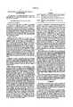
- the approach utilized in capnographyinvolves tracking patient exhalation and measuring expiratory gas CO 2 concentration against time during one or more respiratory cycles. The resulting relationship is plotted to create a graph depicting three distinct phases in breath CO 2 gas concentration during the patient exhale cycle. (See, FIG. 1).
- the three phasesreflect the clearing of the conducting airways which do not normally participate in gas exchange (i.e., airway dead space) (phase I) followed by the exhalation of air from conducting airways dynamically mixed with lung gases from the active (alveoli) membrane surfaces within the lung that have undergone gas exchange with arterial blood (Phase II).
- PetCO 2is a measure of the mean alveolar partial pressure of carbon dioxide from all functional gas exchange units of the lung. PetCO 2 obtained from capnography is a measure of mean alveolar pCO 2 , which value approximates PaCO 2 in normal lungs. Because CO 2 readily diffuses across the alveolar-capillary membrane, the PetCO 2 closely approximates the PaCO 2 with normal ventilation-perfusion.
- PetCO 2 and PaCO 2are primarily a function of the proportion of the lung where gas exchange does not occur (Fletcher, R., Johnson, G., and Brew, J., The Concept of Deadspace with Special Reference to Single Breath Test for Carbon Dioxide. Br. J. Anaesth., 53, 77, 1981).
- breathCO 2peak CO 2
- PaCO 2elevated arterial CO 2
- the instant inventionsets forth a non-invasive system to overcome the problems of the prior art.
- the present inventionprovides a system to rapidly and accurately derive a patient's arterial carbon dioxide concentration and employs a non-invasive method for monitoring arterial partial pressure of carbon dioxide in a patient as an indicator of ventilatory status.
- the present inventionalso comprises a system for detecting expiratory CO 2 concentration and volumetric rate data and accurately deriving actual arterial pCO 2 based thereon.
- the systemaffords non-invasive, substantially real time, determination of blood gas concentrations as derived from current expiratory data as correlated with processed data collected from past expiratory measurements.
- the present inventionconverts expiratory data from a time domain to a volume domain or by accumulating data in the volume domain in the first instance.
- the arterial CO 2 partial pressures of a patientcan then be ascertained by selectively analyzing the slope and intercept values associated with Phase II and Phase III expiratory data in the volume domain. If time domain data is converted to the volume domain, the conversion may be said to "normalize” the data by placing it in the volume domain, wherein time-dependent respiratory differences between patients are eliminated and a standardized gas concentration-to-incremental breath volume relationship is achieved.
- the present inventionalso provides for the accurate determination of arterial CO 2 partial pressures by measuring expiratory gas data and statistically filtering this data to ascertain readings having the highest correlation to actual pulmonary performance with a statistically significant level of confidence.
- the inventive systemprovides for the collection of concise expiratory data from a patient undergoing treatment.
- This dataincludes details on CO 2 gas partial pressure, concentration, and total gas volume sampled during breath exhaust cycle. Multiple readings are made to enhance accuracy.
- the expiratory datais converting to a volume domain from the time domain.
- the expiratory datais then charted to establish the three aforementioned distinct phases within the expiratory cycle.
- the associated linear details of these three phasesare extracted and used to project current arterial CO 2 partial pressure, PaCO 2 . This value is then utilized to quantify pulmonary performance and/or determine the existence of lung failure or distress.
- the systemincludes a sophisticated artificial intelligence engine that iteratively analyzes many separate and distinct measurements and the calculated values associated with the expiratory data. Based on these permutations, the engine quantifies those measured and derived values having the highest correlation to the actual arterial CO 2 partial pressures, resulting in a fixed relationship including specifically weighted variables for projecting arterial CO 2 partial pressures. This relationship, expressed as a vector, is implemented according to system parameters in actual patient monitoring during surgical procedures and other periods of time associated with potential pulmonary failure.
- FIG. 1graphically illustrates three phases of the CO 2 /volume curve in a healthy person
- FIG. 2represents the normal expiration of CO 2 plotted against the expired volume and the represented dead spaces
- FIG. 3is a schematic illustration of a system in accordance with a preferred embodiment of the present invention.
- FIG. 4is a flow chart of a preferred method of the present invention.
- FIG. 5is a capnograph for a healthy individual.
- FIG. 6is a capnograph of a person suffering from lung distress.
- the present inventioncomprises a non-invasive system and procedure for deriving the gas content of arterial blood through analysis of the expiratory gas concentrations and volumes.
- the expiratory gas concentrations and volumesmay be collected in a time domain, typically using a capnometer and pneumotachometer.
- the datamay be collected directly in the volume domain with a time delay or phase-shift correction between the pneumotachometer and capnometer data.
- the raw data for both pCO 2 and volumeare digitized at a frequency high enough to avoid aliasing. In adults with normal ventilatory frequencies, the data is typically collected at 100 Hz, producing a data point every 0.01 seconds. If taken in the time domain, the measurements are converted from the time domain (typically 1 point per 0.01 seconds) to a volume domain (typically 1 point per 1 ml of expired volume) utilizing a polynomial fit.
- the slope of the Phase II curve segmentis calculated.
- the initial point of Phase IIis where the curve transcends a threshold value (typically 0.5% for adults).
- the final point of Phase IIis defined, in this application, as the point at which the curve deviates from linearity by a specified amount (typically 5% for adults).
- the threshold and deviation valuesare based on lung size and respiration rate.
- the slope of the Phase III segmentis calculated, in an analogous manner, by calculating from the last data point of expiration toward Phase II until the curve deviates from linearity by a fixed amount (typically 5% for adults).
- the slopes of the Phase II and Phase III curve segmentsare used as initial input variables, which variables are combined into a vector with other parameters to produce an estimate of content of the gas in the arterial blood, i.e., the partial pressure of CO 2 . or PaCO 2 .
- expired CO 2 pattern obtained from capnographymay be graphically depicted as a three-phase curve.
- the CO 2 curveforms a plateau at the start of Phase III and reaches a value (PetCO 2 ) approximately equal to the PaCO 2 at the end of Phase III.
- the curvedoes not plateau and the final PetCO 2 values are a less reliable indication of the actual PaCO 2 .
- the instant inventiondetermines an estimated value which closely approximates the actual PaCO 2 under these and other conditions.
- the inventive systemis illustrated in FIG. 3 and comprises a differential pressure flowmeter or pneumotachometer (item 15), a flow signal unit (item 14), a gas sensor (item 16), a CO 2 signal unit (item 13), a processor (item 12) and a data display (item 11).
- This systemcan be used with or without mechanical ventilation of the patient.
- flow-measuring devicesuse one of the following methods to determine flow:
- volumemay be measured directly by counting revolutions of a vane placed in the flow path (spinning vane).
- PneumotachographsTheory and Clinical Application, Respiratory Care, Vol. 29-7, pages 736-749 (1984), which is incorporated by reference herein.
- Examples of known differential pressure flowmetersinclude those described in U.S. Pat. Nos. 4,047,521, 4,403,514, 5,038,773, 5,088,332, 5,347,843 and 5,379,650, the teachings of which are incorporated by reference herein.
- the exemplary device for respiratory flow measurementis the differential pressure flowmeter or "pneumotachometer" (FIG. 3, item 15), which provides a pressure differential indicative of respiratory flow, the differential being converted via transducers in flow signal unit (item 14) to electrical signals representative of the relationship between respiratory flow and pressure differential.
- the flowmeter (item 15)is manufactured and sold by Novametrix Medical Systems, Inc., Wallingford, Conn. However, any of the aforementioned types of flow measurement devices may be utilized in the inventive system.
- the currently preferred device for measuring carbon dioxide contentis a gas analyzer of the type employing non-dispersive infrared radiation which presents data representing the % CO 2 (or pCO 2 ) of a sample of exhaled breath.
- gas analyzersinclude those described in U.S. Pat. Nos. 4,859,858, 4,859,859, 4,914,720, 4,958,075, 5,146,092, 5,153,436, 5,206,511 and 5,251,121, the teachings of which patents are incorporated by reference herein.
- Other technologies used to measure the concentration of carbon dioxidesuch as Raman spectroscopy and mass spectroscopy can also be used in the present invention.
- the exemplary gas sensor(FIG. 3, item 16) capable of measuring carbon dioxide content in a patient's exhaled breath is available from Novametrix Medical Systems, Inc., Wallingford, Conn., under the trade name CAPNOSTATM. Other methods of measuring carbon dioxide content both at the airway (mainstream) or by removing a sample (sidestream) may be used in the present invention.
- Gas analyzers as described aboveemploy non-dispersive infrared radiation to measure the concentration of a selected gas in a mixture of gases.
- the infrared radiationcan be emitted from a thick film source and focused by a mirror to pass through the mixture of gases being analyzed. After passing through the gas mixture, the infrared beam is passed through a filter which reflects all of the radiation except for those in the narrow bands centered on a wavelength which is absorbed by the gas of concern (such as CO 2 ) in the mixture being analyzed (such as the air flow from a person's expired breath).
- This narrow band of radiationwhich typically extends approximately 190 angstroms to each side of the wavelength on which the radiation is centered, is allowed to reach a detector which is capable of producing an electrical output signal inversely proportional to the magnitude of the infrared radiation impinging upon it, as the radiation in that band is attenuated to an extent which is proportional to the concentration of the designated gas in the mixture of gases being analyzed.
- the strength of the signal generated by the detectoris consequently inversely proportional to the concentration of the designated gas and can be inverted to provide a signal indicative of that concentration.
- the processorcan be either a personal computer with a suitable digital interface for receiving the digital signals from the CO 2 signal unit (FIG. 3, item 13) and flow signal unit (FIG. 3, item 14), or any specially designed processor capable of calculating the vectors as disclosed further herein.
- capnography systems in the prior arthave attempted to estimate the PaCO 2 by using the peak or end-tidal value for a single breath (PetCO 2 ).
- PetCO 2peak or end-tidal value for a single breath
- Such systemsare effective at tracking gas changes in normal lungs but have been shown to be unreliable in diseased lungs such an COPD or when a significant pulmonary shunt exists.
- the inadequacy of PetCO 2 to measured PaCO 2is in part attributed to regions within the lung with high ventilation to perfusion ratios. Exhaled gases from regions where gas exchange does not occur due to inadequate perfusion reduce the obtained PetCO 2 .
- the increased slope of Phase III due to impaired gas exchangemakes the PetCO 2 valve a less reliable indicator of PaCO 2 .
- the digitized expired CO 2 and flow dataif taken in the time domain, is converted to the volume domain to account for variations between different people and thereby improve accuracy.
- flow signal unit 14may be employed to integrate a flow rate signal on a continuing basis into volume, CO 2 readings then being taken at predetermined volumetric intervals, the phase shift between the two sensors (including signal processing time) being corrected for as data is taken or subsequently processed.
- all datamay be taken in the time domain and converted to the volume domain after the fact by processing unit (FIG. 3, item 12).
- flow volumemay be measured directly, as by a spinning vane device.
- CO 2 concentrations versus respiratory flow or volumemay be depicted as a curve including a series of units, each defined by a pair of points.
- time domainthe progression from unit to unit is based on fractions of a second, regardless of the quantity of air expelled during that time period. The effective rate of sampling depends on the patient's rate of respiration.
- volume domaineach unit to unit movement is based on a unit of volume of air expelled, regardless of the expiratory time.
- the volume domainBy using the volume domain, the latter portion of the breath receives a weighting more indicative of its physiologic importance regardless of the health of the patient. For example, in a mechanically ventilated, chemically paralyzed, patient with COPD experiencing bronchospasm, the exhalation period is prolonged due to the narrowing of the airways (FIG. 6). With pharmaceutical intervention, expiratory resistance can be reduced, thereby reducing time required to complete exhalation. The exhalation time greatly varies between the non-medicated and medicated patient, yet the exhaled CO 2 to total gas volume exhaled ratio is relatively constant. Plotted in the volume domain, the capnograph of non-medicated and medicated patients would be the same. Conversely, in the prior art systems (time domain), measurements taken before and after medication would vary greatly.
- the CO 2 sensormeasures the pCO 2 in the person's expiratory breath.
- the pneumotachometermeasures the flow of the person's expiratory breath using differential pressures across a fixed resistance as previously referenced.
- the differential pressure values from the pneumotachometerare converted to electrical signals and digitized in flow signal unit (item 14) and the analog signals from CO 2 sensor (item 16) are digitized in CO 2 signal unit (item 13).
- the digital signalsare processed, as further disclosed herein, in the processor (item 12) and displayed via printer, VDT, LED or other display devices as known in the art (item 11).
- the estimated PaCO 2 valueis displayed after several breaths.
- the actual lag timeis dependent on the consistency of the data with a minimum of six breaths initially and every third breath thereafter.
- This data flowis illustrated, as part of the complete conversion routine, in FIG. 4.
- the CO 2 sensor (item 16) and associated signal unit (item 13)measures the CO 2 content of the patient's breath.
- the output from the flow sensor (item 15)is representative of the flow of the expiratory breath.
- the pneumotachometer (item 15) outputsare converted via transducers in flow signal unit (item 14) to electrical signals which are digitized as time dependent signals representing the flow rate of the patient's breath, and subsequently integrated into volume. These signals are sent to the processor (item 12).
- the flow data and CO 2 dataare isolated breath-by-breath and converted to the volume domain in order to express a more physiologic relationship.
- the volume domain progression from unit to unitis based on a unit of volume expired without regard to time.
- a variety of variablesare computed which depict features of Phase II, the transition period, and Phase III.
- the computed variablesare selected to include all features and idiosyncrasies of the capnograph.
- the derived variablesare of two types: 1) those with established physiologic importance, and 2) those which mathematically represent features of the capnograph whose physiologic significance is less clear. These derived variables have utility in normalization of the data to allow for diverse lung sizes and respiratory patterns.
- Artificial intelligenceis then used to evaluate each variable and assign a mathematical weight. In particular, a neural network is employed to insure the variables are evaluated without imposing an initial bias. These variables are computed as described hereafter.
- Suitable software systemsare readily available in the marketplace, and are exemplified by the neural network presently offered by NeuralWare, Inc. located at Penn Center West, Building IV, Suite 227, Pittsburgh, Pa. 15276.
- a threshold level of CO 2is detected by finding the point were the curve transcends from a value below 0.5% to a value above 0.5%. In the instant invention, this point is used as the initial point of Phase II. From the threshold point, subsequent CO 2 data points are adjoined and tested for linearity to the data point where the signal deviates from a linear path. The amount of allowed deviation is typically 5% in adults. The point where the deviation occurs marks the termination of Phase II and the slope of the Phase II segment is derived. As described further herein, the Phase II slope is used later. The slope of Phase III is determined in an analogous manner by starting at the last data point of expiration (Pet CO 2 ) and regressing toward the termination point of Phase II. Once the Phase II and III slopes are computed, the remaining input variables are derived as the following:
- the product of these intermediate variables and their assigned mathematical weightsare used in arguments in a hyperbolic scaling function to compute the final PaCO 2 .
- the mathematical weights for each variablewere initially defined from a set of 100 derived variables used as inputs to a fully connected, back-propagation, neural network and the actual arterial carbon dioxide used as the desired output. Once trained for 75,000 iterations, the resultant weights were extracted and used for subsequent derivations where the actual PaCO 2 was to be determined.
- FIG. 4System operation based on the stored vector arguments are shown in the flow chart in FIG. 4.
- the systeminputs the flow data and CO 2 data as isolated breath-by-breath and converted to the volume domain in order to express a more physiologic relationship.
- the volume domain progression from unit to unitis based on a unit of volume expired without regard to time.
- logicbegins at start block 100, and begins a processing loop defined by block 110, defining a sequence of 10 iterations (exemplary).
- the digitized respiratory datais loaded as variable RESP(I), converted to the volume domain at block 130, and then mapped, setting forth the three aforementioned phases of the capnograph, block 140, VRESP(I).
- Phase II thresholdis detected, THRESH(I), followed by block 160 wherein the detection of the Phase II deviation to Phase III, DEVIA(I) is effected.
- the variables for the capnographare determined, VAR(I), at block 170.
- the stored arguments based on the assessed weighting for the vectorare recalled at block 180, and the final vector generated, VEC(I).
- the PaCO 2is derived and stored for the Ith iteration, block 190.
- this processis repeated for the next sequence of respiratory data from the patient, for 10 iterations or breath cycles (exemplary).
- the datais refined by discarding four of the ten readings (two high and two low), XPaCO 2 (I), and the resulting six iteratives are statistically assessed and accepted if meeting a minimum confidential level (95 or 99%), by way of example. If accepted, the mean value of the remaining iterations is displayed, MPaCO 2 (I), block 220. The process continues giving pseudo real time data, as noted at block 230.
- the exemplary datawas computed for each breath contained in a 2-5 minute collection period.
- the calculated PaCO 2 values and standard deviations included in Table IIIwere determined by analysis of the median six (6) values of ten (10) consecutive breaths.
- the standard deviations for the six (6) median values for each patientwere computed for assurance of reproducibility of the data.
- the computed valueswere then compared to the PaCO 2 ABG values obtained simultaneously from an arterial blood gas sample. Using this method the accuracy for determination of PaCO 2 by the method of the instant invention is typically about ⁇ 2 mmHg.
- the actual data range for a 95 or 99% confidence levelsmay be graphically displayed, as on the data display (FIG. 3, item 11).
Landscapes
- Health & Medical Sciences (AREA)
- Life Sciences & Earth Sciences (AREA)
- Medical Informatics (AREA)
- Animal Behavior & Ethology (AREA)
- Veterinary Medicine (AREA)
- Biophysics (AREA)
- Pathology (AREA)
- Engineering & Computer Science (AREA)
- Biomedical Technology (AREA)
- Heart & Thoracic Surgery (AREA)
- Public Health (AREA)
- Molecular Biology (AREA)
- Surgery (AREA)
- Physics & Mathematics (AREA)
- General Health & Medical Sciences (AREA)
- Immunology (AREA)
- Vascular Medicine (AREA)
- Emergency Medicine (AREA)
- Obesity (AREA)
- Physiology (AREA)
- Pulmonology (AREA)
- Measurement Of The Respiration, Hearing Ability, Form, And Blood Characteristics Of Living Organisms (AREA)
- Investigating Or Analysing Biological Materials (AREA)
Abstract
Description
TABLE I ______________________________________ Phase I Represents CO.sub.2 -free gas expired from the airway conduction structures where gas exchange does not occur, Phase II The S-shaped upswing in CO.sub.2 concentration (expressed as a percent) represents the transition from airway to alveolar gas, and Phase III The alveolar plateau representing CO.sub.2 rich gas from the alveoli. ______________________________________
______________________________________ ABBREVIATIONS AND DEFINTIONS ______________________________________ CO.sub.2 Carbon dioxide pCO.sub.2 Partial pressure of carbon dioxide PetCO.sub.2 End tidal CO.sub.2 PECO.sub.2 Expiratory CO.sub.2 PaCO.sub.2 Arterial partial pressure of CO.sub.2 PaCO.sub.2.sup.ABG Arterial partial pressure of CO.sub.2 measured by an arterial blood gas analyzer % CO.sub.2 Carbon dioxide value expressed as a percentage of the total gas content COPD Chronic obstruction pulmonary disease ml Milliliters fds Fowler dead space (Airway dead space) I2 Intercept of Phase II on CO.sub.2 axis I3 Intercept of Phase III on CO.sub.2 axis m2 Slope of Phase II m3 Slope of Phase III ph2i Phase II deviation index ph3i Phase III deviation index Th Phase transition bend Tbi Phase transition bend index TV Tidal volume of air exhaled ang Angle between Phases II and III ______________________________________
TABLE II ______________________________________ Fds The Fowler dead space volume is determined by examining the volume that gives equal area between the start of the Phase II data and the start of the Phase III data. This computation is done by fractional difference. (Fowler W. S. Lung Function Studies II. The Respiratory Dead Space. Am. J. Physiol. 154: 405, 1948 - the teachings of which are hereby incorporated by reference). i2 The CO.sub.2 axis intercept of Phase II. The effective Phase II slope (m0) is used at the Fds volume. The equation is: i2 = modelCO.sub.2 (Fds) - m0 * Fds where modelCO.sub.2 (Fds) is the model evaluated at Fds. m3 The slope of Phase III. i3 The CO.sub.2 axis intercept of Phase III. The Phase III slope is used at the end tidal volume. The equation is: i2 = modelCO.sub.2 (PetCO.sub.2) - m3 * PetCO.sub.2 where modelCO.sub.2 (PetCO.sub.2) is the model evaluated at PetCO.sub.2. ang The angle in degrees between the Phase II and Phase III. The effective slope of Phase II (m0) is used. The angle between the lines is: (tan(m3) - tan(m0) + π) * (180/π). PetCO.sub.2 The end tidal value of pCO.sub.2. The last element in the CO.sub.2 (vol) data array is used for PetCo.sub.2. TV The total volume of air exhaled expressed in ml. ph2i The Phase II deviation index. This is smallest volume at which the Phase II line deviates from the smoothed CO.sub.2 data. The comparison is done by fractional difference. ph3i The Phase III deviation index. This is the smallest volume at which the Phase III line deviates from the smoothed CO.sub.2 data by the phase transition width (Tw). The negative of the second derivative of the model curve exhibits a peak in the region between Phase II and Phase III. The width of this peak is Tw and is determined as the full width at half the maximum of the peak. All second derivative curves have peaks that fall below half the maximum of increasing volume. However, the peaks in some derivative curves do not fall to 1/2 the maximum for decreasing volume. Thus, Tw is found from the right side half- width of the peak at half-maximum and multiplying by 2 to construct the full-width. Th The phase transition bend. This value is the maximum of the negative of the second derivative of the model curve. It reflects the measure of the sharpness of the transition. Thi The phase transition bend index. This value is the index (volume) at which the phase transition bend (Tb) occurs. Mod- A modified version of the angle in degrees between the Phase II Ang and Phase III lines. The modification scales the actual angle to enhance differences in the model fit curves. The scaling is heuristic. The modified angle is computed as: (tan(400 * m3) - tan(400 * m0) + π)(180/π). ______________________________________
TABLE III ______________________________________ Derived PaCO.sub.2 PaCO.sub.2 Patient No. PaCO.sub.2.sup.ABG mean std err ______________________________________ 1. 33.00 34.30 2.40 1.30 2. 33.00 31.33 1.84 1.67 3. 33.00 32.20 2.33 0.80 4. 33.50 32.00 1.77 1.50 5. 38.30 39.67 1.36 1.39 6. 40.00 38.37 0.86 1.63 7. 40.00 41.38 0.62 1.38 8. 42.00 42.63 0.15 0.63 9. 42.00 44.01 1.60 2.01 10. 44.00 45.47 0.18 1.47 11. 45.00 45.66 2.35 0.66 12. 46.00 46.40 1.31 0.40 13. 47.00 47.42 0.96 0.42 14. 49.00 51.03 0.12 2.03 15. 50.50 50.73 0.50 0.23 16. 51.00 49.77 0.31 1.23 17. 51.00 52.07 1.29 1.07 18. 51.00 52.22 0.69 1.22 19. 53.00 53.20 0.72 0.20 20. 57.00 56.60 1.22 1.00 21. 63.00 63.34 0.23 0.34 22. 65.00 62.20 0.77 2.80 23. 67.00 64.98 0.62 2.02 ______________________________________
Claims (19)
Priority Applications (4)
| Application Number | Priority Date | Filing Date | Title |
|---|---|---|---|
| US08/592,726US5800361A (en) | 1995-02-06 | 1996-01-26 | Non-invasive estimation of arterial blood gases |
| PCT/US1996/001538WO1996024285A1 (en) | 1995-02-06 | 1996-02-06 | Non-invasive estimation of arterial blood gases |
| EP96905370AEP0808126A1 (en) | 1995-02-06 | 1996-02-06 | Non-invasive estimation of arterial blood gases |
| US09/141,248US6251082B1 (en) | 1995-02-06 | 1998-08-27 | Non-invasive estimation of arterial blood gases |
Applications Claiming Priority (2)
| Application Number | Priority Date | Filing Date | Title |
|---|---|---|---|
| US08/384,519US5632281A (en) | 1995-02-06 | 1995-02-06 | Non-invasive estimation of arterial blood gases |
| US08/592,726US5800361A (en) | 1995-02-06 | 1996-01-26 | Non-invasive estimation of arterial blood gases |
Related Parent Applications (1)
| Application Number | Title | Priority Date | Filing Date |
|---|---|---|---|
| US08/384,519Continuation-In-PartUS5632281A (en) | 1995-02-06 | 1995-02-06 | Non-invasive estimation of arterial blood gases |
Related Child Applications (1)
| Application Number | Title | Priority Date | Filing Date |
|---|---|---|---|
| US09/141,248ContinuationUS6251082B1 (en) | 1995-02-06 | 1998-08-27 | Non-invasive estimation of arterial blood gases |
Publications (1)
| Publication Number | Publication Date |
|---|---|
| US5800361Atrue US5800361A (en) | 1998-09-01 |
Family
ID=27010638
Family Applications (2)
| Application Number | Title | Priority Date | Filing Date |
|---|---|---|---|
| US08/592,726Expired - LifetimeUS5800361A (en) | 1995-02-06 | 1996-01-26 | Non-invasive estimation of arterial blood gases |
| US09/141,248Expired - LifetimeUS6251082B1 (en) | 1995-02-06 | 1998-08-27 | Non-invasive estimation of arterial blood gases |
Family Applications After (1)
| Application Number | Title | Priority Date | Filing Date |
|---|---|---|---|
| US09/141,248Expired - LifetimeUS6251082B1 (en) | 1995-02-06 | 1998-08-27 | Non-invasive estimation of arterial blood gases |
Country Status (3)
| Country | Link |
|---|---|
| US (2) | US5800361A (en) |
| EP (1) | EP0808126A1 (en) |
| WO (1) | WO1996024285A1 (en) |
Cited By (33)
| Publication number | Priority date | Publication date | Assignee | Title |
|---|---|---|---|---|
| US6046453A (en)* | 1998-03-13 | 2000-04-04 | Datex-Ohmeda, Inc. | Agent identification for anesthetic gas monitors using minimum alveolar concentration (MAC) values |
| US6099481A (en)* | 1997-11-03 | 2000-08-08 | Ntc Technology, Inc. | Respiratory profile parameter determination method and apparatus |
| US6241683B1 (en)* | 1998-02-20 | 2001-06-05 | INSTITUT DE RECHERCHES CLINIQUES DE MONTRéAL (IRCM) | Phonospirometry for non-invasive monitoring of respiration |
| US6251082B1 (en)* | 1995-02-06 | 2001-06-26 | Ntc Technology, Inc. | Non-invasive estimation of arterial blood gases |
| US20020082511A1 (en)* | 1999-06-08 | 2002-06-27 | Ephraim Carlebach | Waveform interpreter for respiratory analysis |
| WO2003008027A1 (en)* | 2001-07-19 | 2003-01-30 | Resmed Ltd. | Pressure support ventilation of patients |
| US6575918B2 (en) | 2001-09-27 | 2003-06-10 | Charlotte-Mecklenburg Hospital | Non-invasive device and method for the diagnosis of pulmonary vascular occlusions |
| US6585662B1 (en)* | 2001-01-19 | 2003-07-01 | Boston Medical Technologies, Inc. | Pneumotachometer |
| US6648833B2 (en) | 2001-10-15 | 2003-11-18 | David R. Hampton | Respiratory analysis with capnography |
| US20030217747A1 (en)* | 2002-02-25 | 2003-11-27 | Scott Laboratories, Inc. | Fail-safe module integral with a sedation and analgesia system and method |
| EP1251773A4 (en)* | 2000-02-02 | 2005-06-15 | Healthetech Inc | Indirect calorimeter for medical applications |
| US6938619B1 (en) | 2000-06-13 | 2005-09-06 | Scott Laboratories, Inc. | Mask free delivery of oxygen and ventilatory monitoring |
| US20050211249A1 (en)* | 2002-11-19 | 2005-09-29 | Mirko Wagner | Ventilator method, ventilator and memory medium |
| US20060253038A1 (en)* | 2000-02-22 | 2006-11-09 | Kai Kuck | Methods and apparatus for improving time domain relationships between signals obtained from respiration |
| US20070084464A1 (en)* | 2000-08-29 | 2007-04-19 | Wickham Peter John D | Respiratory apparatus with improved flow-flattening detection |
| US20070218559A1 (en)* | 2006-03-15 | 2007-09-20 | Franco Wayne P | Method for performing a non-invasive blood gas test |
| USRE39966E1 (en)* | 1998-03-31 | 2008-01-01 | Hongwei Zhao | Apparatus and method for generating pressure changes in a mammalian oral/throat cavity |
| US8166971B2 (en)* | 2007-03-15 | 2012-05-01 | Ric Investments, Llc | End-tidal gas estimation system and method |
| US8176915B2 (en)* | 2007-03-15 | 2012-05-15 | Koninklijke Philips Electronics N.V. | End-tidal gas estimation system and method |
| US8335992B2 (en) | 2009-12-04 | 2012-12-18 | Nellcor Puritan Bennett Llc | Visual indication of settings changes on a ventilator graphical user interface |
| US8443294B2 (en) | 2009-12-18 | 2013-05-14 | Covidien Lp | Visual indication of alarms on a ventilator graphical user interface |
| US8453645B2 (en) | 2006-09-26 | 2013-06-04 | Covidien Lp | Three-dimensional waveform display for a breathing assistance system |
| US8555881B2 (en) | 1997-03-14 | 2013-10-15 | Covidien Lp | Ventilator breath display and graphic interface |
| US8597198B2 (en) | 2006-04-21 | 2013-12-03 | Covidien Lp | Work of breathing display for a ventilation system |
| US8924878B2 (en) | 2009-12-04 | 2014-12-30 | Covidien Lp | Display and access to settings on a ventilator graphical user interface |
| US20150151072A1 (en)* | 2008-06-30 | 2015-06-04 | Oridion Medical 1987 Ltd. | Ventilation analysis and monitoring |
| US9119925B2 (en) | 2009-12-04 | 2015-09-01 | Covidien Lp | Quick initiation of respiratory support via a ventilator user interface |
| US9262588B2 (en) | 2009-12-18 | 2016-02-16 | Covidien Lp | Display of respiratory data graphs on a ventilator graphical user interface |
| US9950129B2 (en) | 2014-10-27 | 2018-04-24 | Covidien Lp | Ventilation triggering using change-point detection |
| US20180289882A1 (en)* | 2017-04-10 | 2018-10-11 | Fresenius Medical Care Holdings, Inc. | Optical detection of air bubbles in either saline or blood or a mixture of both |
| US10362967B2 (en) | 2012-07-09 | 2019-07-30 | Covidien Lp | Systems and methods for missed breath detection and indication |
| US11324954B2 (en) | 2019-06-28 | 2022-05-10 | Covidien Lp | Achieving smooth breathing by modified bilateral phrenic nerve pacing |
| US11672934B2 (en) | 2020-05-12 | 2023-06-13 | Covidien Lp | Remote ventilator adjustment |
Families Citing this family (32)
| Publication number | Priority date | Publication date | Assignee | Title |
|---|---|---|---|---|
| US6306098B1 (en) | 1996-12-19 | 2001-10-23 | Novametrix Medical Systems Inc. | Apparatus and method for non-invasively measuring cardiac output |
| AU2622800A (en)* | 1999-01-21 | 2000-08-07 | Metasensors, Inc. | Non-invasive cardiac output and pulmonary function monitoring using respired gasanalysis techniques and physiological modeling |
| US6413226B1 (en) | 1999-10-22 | 2002-07-02 | Respironics, Inc. | Method and apparatus for determining cardiac output |
| US20050037374A1 (en)* | 1999-11-08 | 2005-02-17 | Melker Richard J. | Combined nanotechnology and sensor technologies for simultaneous diagnosis and treatment |
| US20050233459A1 (en)* | 2003-11-26 | 2005-10-20 | Melker Richard J | Marker detection method and apparatus to monitor drug compliance |
| JP4773019B2 (en) | 1999-11-08 | 2011-09-14 | ユニバーシティ オブ フロリダ リサーチ ファンデーション インコーポレーティッド | Marker detection method and apparatus for monitoring drug compliance |
| US7699788B2 (en) | 2000-02-22 | 2010-04-20 | Ric Investments, Llc. | Noninvasive effective lung volume estimation |
| US7104963B2 (en) | 2002-01-22 | 2006-09-12 | University Of Florida Research Foundation, Inc. | Method and apparatus for monitoring intravenous (IV) drug concentration using exhaled breath |
| US6981947B2 (en) | 2002-01-22 | 2006-01-03 | University Of Florida Research Foundation, Inc. | Method and apparatus for monitoring respiratory gases during anesthesia |
| US7135001B2 (en) | 2001-03-20 | 2006-11-14 | Ric Investments, Llc | Rebreathing methods including oscillating, substantially equal rebreathing and nonrebreathing periods |
| US7052854B2 (en)* | 2001-05-23 | 2006-05-30 | University Of Florida Research Foundation, Inc. | Application of nanotechnology and sensor technologies for ex-vivo diagnostics |
| WO2002095359A2 (en)* | 2001-05-23 | 2002-11-28 | University Of Florida | Method and apparatus for detecting illicit substances |
| US7052468B2 (en)* | 2001-05-24 | 2006-05-30 | University Of Florida Research Foundation, Inc. | Method and apparatus for detecting environmental smoke exposure |
| US20070167853A1 (en)* | 2002-01-22 | 2007-07-19 | Melker Richard J | System and method for monitoring health using exhaled breath |
| JP2005537041A (en)* | 2002-05-13 | 2005-12-08 | スコット・ラボラトリーズ・インコーポレイテッド | Transparent early detection, warning, and intervention systems and methods in medical procedures |
| US20060160134A1 (en)* | 2002-10-21 | 2006-07-20 | Melker Richard J | Novel application of biosensors for diagnosis and treatment of disease |
| WO2004049912A2 (en)* | 2002-12-02 | 2004-06-17 | Scott Laboratories, Inc. | Respiratory monitoring systems and methods |
| US8021308B2 (en) | 2003-06-19 | 2011-09-20 | Capnia, Inc. | Breath end-tidal gas monitor |
| US20050191757A1 (en)* | 2004-01-20 | 2005-09-01 | Melker Richard J. | Method and apparatus for detecting humans and human remains |
| EP1579882A1 (en)* | 2004-03-26 | 2005-09-28 | Stephan Dr. Böhm | Non-invasive method and apparatus for optimizing the respiration for atelectatic lungs |
| DE102004039194A1 (en)* | 2004-08-12 | 2006-02-23 | Universitätsklinikum Freiburg | Apparatus and method for detecting and evaluating expirograms |
| US20060062734A1 (en)* | 2004-09-20 | 2006-03-23 | Melker Richard J | Methods and systems for preventing diversion of prescription drugs |
| US20060257883A1 (en)* | 2005-05-10 | 2006-11-16 | Bjoraker David G | Detection and measurement of hematological parameters characterizing cellular blood components |
| US7914460B2 (en)* | 2006-08-15 | 2011-03-29 | University Of Florida Research Foundation, Inc. | Condensate glucose analyzer |
| US20080117416A1 (en)* | 2006-10-27 | 2008-05-22 | Hunter Ian W | Use of coherent raman techniques for medical diagnostic and therapeutic purposes, and calibration techniques for same |
| KR20150024299A (en) | 2011-12-21 | 2015-03-06 | 카프니아, 인코포레이티드 | Collection and analysis of a volume of exhaled gas with compensation for the frequency of a breathing parameter |
| JP6424172B2 (en) | 2013-01-08 | 2018-11-14 | キャプニア, インク.Capnia, Inc. | Breathing selection for analysis |
| CN105101873A (en) | 2013-02-12 | 2015-11-25 | 卡普尼亚公司 | Sampling and storage registry device for breath gas analysis |
| CA2922356C (en) | 2013-08-30 | 2023-01-03 | Capnia, Inc. | Neonatal carbon dioxide measurement system |
| US10568568B2 (en) | 2014-08-27 | 2020-02-25 | Capnia, Inc. | Methods for immune globulin administration |
| JP7186174B2 (en)* | 2016-12-05 | 2022-12-08 | メディパインズ コーポレイション | Systems and methods for respiration measurements using respiratory gas samples |
| CN109730680A (en)* | 2019-03-07 | 2019-05-10 | 核工业四一六医院 | Partial pressure of carbon dioxide in endexpiratory gas monitoring device is in anesthesia recovery room clinical testing procedure |
Citations (7)
| Publication number | Priority date | Publication date | Assignee | Title |
|---|---|---|---|---|
| US4608995A (en)* | 1983-01-19 | 1986-09-02 | Karolinska Institutet Institutionen For Medicinsk Teknik | Method and apparatus for the non-invasive determination of the minute volume of the heart |
| US4909259A (en)* | 1989-04-21 | 1990-03-20 | Tehrani Fleur T | Method and apparatus for determining metabolic rate ratio |
| US4947860A (en)* | 1985-10-10 | 1990-08-14 | Joseph Fisher | Non-invasive method and apparatus for measuring mixed venous carbon dioxide pressure (PvCO2) and other physiological variables |
| US4986268A (en)* | 1988-04-06 | 1991-01-22 | Tehrani Fleur T | Method and apparatus for controlling an artificial respirator |
| US5339818A (en)* | 1989-09-20 | 1994-08-23 | University Of Utah Research Foundation | Method for determining blood pressure utilizing a neural network |
| US5355880A (en)* | 1992-07-06 | 1994-10-18 | Sandia Corporation | Reliable noninvasive measurement of blood gases |
| US5402796A (en)* | 1990-09-19 | 1995-04-04 | University Of Melbourne | Arterial CO2 Monitor and closed loop controller |
Family Cites Families (4)
| Publication number | Priority date | Publication date | Assignee | Title |
|---|---|---|---|---|
| US4423739A (en)* | 1981-08-24 | 1984-01-03 | Andros Analyzers Incorporated | End tidal carbon dioxide gas analyzer |
| SE465497B (en) | 1989-11-24 | 1991-09-23 | Minco Ab | DEVICE FOR STUDYING A PERSON'S LUNG FUNCTION |
| US5800361A (en)* | 1995-02-06 | 1998-09-01 | Ntc Technology Inc. | Non-invasive estimation of arterial blood gases |
| US5632281A (en)* | 1995-02-06 | 1997-05-27 | Rayburn; Daniel B. | Non-invasive estimation of arterial blood gases |
- 1996
- 1996-01-26USUS08/592,726patent/US5800361A/ennot_activeExpired - Lifetime
- 1996-02-06EPEP96905370Apatent/EP0808126A1/ennot_activeWithdrawn
- 1996-02-06WOPCT/US1996/001538patent/WO1996024285A1/ennot_activeApplication Discontinuation
- 1998
- 1998-08-27USUS09/141,248patent/US6251082B1/ennot_activeExpired - Lifetime
Patent Citations (7)
| Publication number | Priority date | Publication date | Assignee | Title |
|---|---|---|---|---|
| US4608995A (en)* | 1983-01-19 | 1986-09-02 | Karolinska Institutet Institutionen For Medicinsk Teknik | Method and apparatus for the non-invasive determination of the minute volume of the heart |
| US4947860A (en)* | 1985-10-10 | 1990-08-14 | Joseph Fisher | Non-invasive method and apparatus for measuring mixed venous carbon dioxide pressure (PvCO2) and other physiological variables |
| US4986268A (en)* | 1988-04-06 | 1991-01-22 | Tehrani Fleur T | Method and apparatus for controlling an artificial respirator |
| US4909259A (en)* | 1989-04-21 | 1990-03-20 | Tehrani Fleur T | Method and apparatus for determining metabolic rate ratio |
| US5339818A (en)* | 1989-09-20 | 1994-08-23 | University Of Utah Research Foundation | Method for determining blood pressure utilizing a neural network |
| US5402796A (en)* | 1990-09-19 | 1995-04-04 | University Of Melbourne | Arterial CO2 Monitor and closed loop controller |
| US5355880A (en)* | 1992-07-06 | 1994-10-18 | Sandia Corporation | Reliable noninvasive measurement of blood gases |
Non-Patent Citations (18)
| Title |
|---|
| Blanch, Lluis, et al., "Relationship Between Expired Capnogram and Respiratory System Resistance in Critically Ill Patients During Total Ventilatory Support", Chest, vol. 105; No. 1; ISSN: 0012-3692 (Database version of article), Jan. 1994. |
| Blanch, Lluis, et al., Relationship Between Expired Capnogram and Respiratory System Resistance in Critically Ill Patients During Total Ventilatory Support , Chest , vol. 105; No. 1; ISSN: 0012 3692 (Database version of article), Jan. 1994.* |
| Bongard, Fred, et al., Pulse Oximetry and Capnography in Intensive and Transitional Care Units; Summary from the Medical Surgical Critical Care Conference, Harbor UCLA Medical Center, California Medical Association, The Western Journal of Medicine , vol. 156; No. 1; ISSN: 0093 0415 (Database version of article), Jan. 1992.* |
| Bongard, Fred, et al., Pulse Oximetry and Capnography in Intensive and Transitional Care Units; Summary from the Medical-Surgical Critical Care Conference, Harbor-UCLA Medical Center, California Medical Association, The Western Journal of Medicine, vol. 156; No. 1; ISSN: 0093-0415 (Database version of article), Jan. 1992. |
| Callaham, Michael, "Measuring Exhaled Carbon Dioxide in Cardiac Arrest; Emergency Medicine", California Medical Association, The Western Journal of Medicine, vol. 151; No. 1; ISSN: 0093-0415 (Database version of article), Jul. 1989. |
| Callaham, Michael, Measuring Exhaled Carbon Dioxide in Cardiac Arrest; Emergency Medicine , California Medical Association, The Western Journal of Medicine , vol. 151; No. 1; ISSN: 0093 0415 (Database version of article), Jul. 1989.* |
| Fletcher, Roger, The Single Breath Test for Carbon Dioxide, University of Lund, Lund, Sweden, 1980; pp. 1 113 (entire work).* |
| Fletcher, Roger, The Single Breath Test for Carbon Dioxide, University of Lund, Lund, Sweden, 1980; pp. 1-113 (entire work). |
| Jordanoglou, J., et al, "Measurement of Effective Alveolar Carbon Dioxide Tension During Spontaneous Breathing in Normal Subjects and Patients With Chronic Airways Obstruction" Thorax, University of Athens, Medical School, Athens, Greece, Nov. 16, 1994. |
| Jordanoglou, J., et al, Measurement of Effective Alveolar Carbon Dioxide Tension During Spontaneous Breathing in Normal Subjects and Patients With Chronic Airways Obstruction Thorax , University of Athens, Medical School, Athens, Greece, Nov. 16, 1994.* |
| Maltais, Francois, et al., "Respiratory Mechanics In Status Asthmaticus: Effects of Inhalational Anesthesia", Chest, vol. 106; No. 5; ISSN: 0012-3692 (Database version of article), Nov. 1994. |
| Maltais, Francois, et al., Respiratory Mechanics In Status Asthmaticus: Effects of Inhalational Anesthesia , Chest , vol. 106; No. 5; ISSN: 0012 3692 (Database version of article), Nov. 1994.* |
| Sanders, Mark H., et al. "Accuracy of End-Tidal and Transcutaneous PCO2 Monitoring During Sleep", Chest, vol. 106; No. 2; ISSN: 0012-3692 (Database Version of Article); Aug. 1994. |
| Sanders, Mark H., et al. Accuracy of End Tidal and Transcutaneous PCO 2 Monitoring During Sleep , Chest , vol. 106; No. 2; ISSN: 0012 3692 (Database Version of Article); Aug. 1994.* |
| Weil, Max Harry, et al., "End Tidal PCO2 During Cardiopulmonary Resuscitation; Carbon Dioxide Tension", The Journal of American Medical Association, vol. 263; No. 6; ISSN: 0098-7484; (Database version of article), Feb. 9, 1990. |
| Weil, Max Harry, et al., End Tidal PCO 2 During Cardiopulmonary Resuscitation; Carbon Dioxide Tension , The Journal of American Medical Association , vol. 263; No. 6; ISSN: 0098 7484; (Database version of article), Feb. 9, 1990.* |
| Zimmerman, Mark, et al, "Estimated vs. Actual Values for Dead Space/Tidal Volume Ratios During Incremental Exercise in Patients Evaluated for Dyspnea", Chest, vol. 106; No. 1; ISSN: 0012-3692 (Database version of article); Jul. 1994. |
| Zimmerman, Mark, et al, Estimated vs. Actual Values for Dead Space/Tidal Volume Ratios During Incremental Exercise in Patients Evaluated for Dyspnea , Chest , vol. 106; No. 1; ISSN: 0012 3692 (Database version of article); Jul. 1994.* |
Cited By (69)
| Publication number | Priority date | Publication date | Assignee | Title |
|---|---|---|---|---|
| US6251082B1 (en)* | 1995-02-06 | 2001-06-26 | Ntc Technology, Inc. | Non-invasive estimation of arterial blood gases |
| US8555881B2 (en) | 1997-03-14 | 2013-10-15 | Covidien Lp | Ventilator breath display and graphic interface |
| US8555882B2 (en) | 1997-03-14 | 2013-10-15 | Covidien Lp | Ventilator breath display and graphic user interface |
| US6099481A (en)* | 1997-11-03 | 2000-08-08 | Ntc Technology, Inc. | Respiratory profile parameter determination method and apparatus |
| US6179784B1 (en) | 1997-11-03 | 2001-01-30 | Ntc Technology Inc. | Respiratory profile parameter determination method and apparatus |
| US8251914B2 (en) | 1997-11-03 | 2012-08-28 | Ric Investments, Llc | Respiratory profile parameter determination method and apparatus |
| US7662106B2 (en)* | 1997-11-03 | 2010-02-16 | Ric Investments, Llc. | Respiratory profile parameter determination apparatus |
| US20100097380A1 (en)* | 1997-11-03 | 2010-04-22 | Ric Investments, Llc | Respiratory profile parameter determination method and apparatus |
| US6471658B1 (en) | 1997-11-03 | 2002-10-29 | Ntc Technology, Inc. | Respiratory profile parameter determination method and apparatus |
| US20030045807A1 (en)* | 1997-11-03 | 2003-03-06 | Rich Daniels | Respiratory profile parameter determination method and apparatus |
| US6241683B1 (en)* | 1998-02-20 | 2001-06-05 | INSTITUT DE RECHERCHES CLINIQUES DE MONTRéAL (IRCM) | Phonospirometry for non-invasive monitoring of respiration |
| US6046453A (en)* | 1998-03-13 | 2000-04-04 | Datex-Ohmeda, Inc. | Agent identification for anesthetic gas monitors using minimum alveolar concentration (MAC) values |
| USRE39966E1 (en)* | 1998-03-31 | 2008-01-01 | Hongwei Zhao | Apparatus and method for generating pressure changes in a mammalian oral/throat cavity |
| US6428483B1 (en) | 1999-05-08 | 2002-08-06 | Oridion Medical 1987, Ltd. | Waveform interpreter for respiratory analysis |
| US6997880B2 (en)* | 1999-06-08 | 2006-02-14 | Oridion Medical 1987, Ltd. | Waveform interpreter for respiratory analysis |
| US20020082511A1 (en)* | 1999-06-08 | 2002-06-27 | Ephraim Carlebach | Waveform interpreter for respiratory analysis |
| EP1251773A4 (en)* | 2000-02-02 | 2005-06-15 | Healthetech Inc | Indirect calorimeter for medical applications |
| US8398559B2 (en)* | 2000-02-22 | 2013-03-19 | Respironics, Inc. | Methods and apparatus for improving time domain relationships between signals obtained from respiration |
| US20060253038A1 (en)* | 2000-02-22 | 2006-11-09 | Kai Kuck | Methods and apparatus for improving time domain relationships between signals obtained from respiration |
| US6938619B1 (en) | 2000-06-13 | 2005-09-06 | Scott Laboratories, Inc. | Mask free delivery of oxygen and ventilatory monitoring |
| US7152604B2 (en) | 2000-06-13 | 2006-12-26 | Scott Laboratories, Inc. | Apparatus and method for mask free delivery of an inspired gas mixture and gas sampling |
| US20070095347A1 (en)* | 2000-06-13 | 2007-05-03 | Scott Laboratories, Inc. | Apparatus and method for mask free delivery of an inspired gas mixture and gas sampling |
| US7997271B2 (en)* | 2000-06-13 | 2011-08-16 | Scott Laboratories, Inc | Apparatus and method for mask free delivery of an inspired gas mixture and gas sampling |
| US9782133B2 (en) | 2000-08-29 | 2017-10-10 | Resmed Limited | Respiratory apparatus with improved flow-flattening detection |
| US20070084464A1 (en)* | 2000-08-29 | 2007-04-19 | Wickham Peter John D | Respiratory apparatus with improved flow-flattening detection |
| US8739789B2 (en)* | 2000-08-29 | 2014-06-03 | Resmed Limited | Respiratory apparatus with improved flow-flattening detection |
| US8707953B2 (en) | 2000-08-29 | 2014-04-29 | Resmed Limited | Respiratory apparatus with improved flow-flattening detection |
| US6585662B1 (en)* | 2001-01-19 | 2003-07-01 | Boston Medical Technologies, Inc. | Pneumotachometer |
| US10046127B2 (en) | 2001-07-19 | 2018-08-14 | Redmed Limited | Pressure support ventilation of patients |
| US20090173347A1 (en)* | 2001-07-19 | 2009-07-09 | Michael Berthon-Jones | Pressure support ventilation of patients |
| WO2003008027A1 (en)* | 2001-07-19 | 2003-01-30 | Resmed Ltd. | Pressure support ventilation of patients |
| US7520279B2 (en) | 2001-07-19 | 2009-04-21 | Resmed Limited | Pressure support ventilation of patients |
| CN1313172C (en)* | 2001-07-19 | 2007-05-02 | 雷斯姆德公司 | Method and device for pressure support ventilation of a patient |
| US20030221689A1 (en)* | 2001-07-19 | 2003-12-04 | Michael Berthon-Jones | Pressure support ventilation of patients |
| US8225789B2 (en) | 2001-07-19 | 2012-07-24 | Resmed Limited | Pressure support ventilation of patients |
| US6575918B2 (en) | 2001-09-27 | 2003-06-10 | Charlotte-Mecklenburg Hospital | Non-invasive device and method for the diagnosis of pulmonary vascular occlusions |
| US6648833B2 (en) | 2001-10-15 | 2003-11-18 | David R. Hampton | Respiratory analysis with capnography |
| US20030217747A1 (en)* | 2002-02-25 | 2003-11-27 | Scott Laboratories, Inc. | Fail-safe module integral with a sedation and analgesia system and method |
| US7527052B2 (en) | 2002-02-25 | 2009-05-05 | Scott Laboratories, Inc. | Fail-safe module integral with a sedation and analgesia system and method |
| US8555876B2 (en) | 2002-02-25 | 2013-10-15 | Scott Laboratories, Inc. | Fail-safe module integral with a sedation and analgesia system and method |
| US20090199851A1 (en)* | 2002-02-25 | 2009-08-13 | Scott Laboratories, Inc | Fail-safe module integral with a sedation and analgesia system and method |
| US20050211249A1 (en)* | 2002-11-19 | 2005-09-29 | Mirko Wagner | Ventilator method, ventilator and memory medium |
| US20070218559A1 (en)* | 2006-03-15 | 2007-09-20 | Franco Wayne P | Method for performing a non-invasive blood gas test |
| US7291502B2 (en)* | 2006-03-15 | 2007-11-06 | Franco Wayne P | Method for performing a non-invasive blood gas test |
| US10582880B2 (en) | 2006-04-21 | 2020-03-10 | Covidien Lp | Work of breathing display for a ventilation system |
| US8597198B2 (en) | 2006-04-21 | 2013-12-03 | Covidien Lp | Work of breathing display for a ventilation system |
| US8453645B2 (en) | 2006-09-26 | 2013-06-04 | Covidien Lp | Three-dimensional waveform display for a breathing assistance system |
| US8166971B2 (en)* | 2007-03-15 | 2012-05-01 | Ric Investments, Llc | End-tidal gas estimation system and method |
| US8176915B2 (en)* | 2007-03-15 | 2012-05-15 | Koninklijke Philips Electronics N.V. | End-tidal gas estimation system and method |
| US20150151072A1 (en)* | 2008-06-30 | 2015-06-04 | Oridion Medical 1987 Ltd. | Ventilation analysis and monitoring |
| US8924878B2 (en) | 2009-12-04 | 2014-12-30 | Covidien Lp | Display and access to settings on a ventilator graphical user interface |
| US9119925B2 (en) | 2009-12-04 | 2015-09-01 | Covidien Lp | Quick initiation of respiratory support via a ventilator user interface |
| US8335992B2 (en) | 2009-12-04 | 2012-12-18 | Nellcor Puritan Bennett Llc | Visual indication of settings changes on a ventilator graphical user interface |
| US8499252B2 (en) | 2009-12-18 | 2013-07-30 | Covidien Lp | Display of respiratory data graphs on a ventilator graphical user interface |
| US9262588B2 (en) | 2009-12-18 | 2016-02-16 | Covidien Lp | Display of respiratory data graphs on a ventilator graphical user interface |
| US8443294B2 (en) | 2009-12-18 | 2013-05-14 | Covidien Lp | Visual indication of alarms on a ventilator graphical user interface |
| US10362967B2 (en) | 2012-07-09 | 2019-07-30 | Covidien Lp | Systems and methods for missed breath detection and indication |
| US11642042B2 (en) | 2012-07-09 | 2023-05-09 | Covidien Lp | Systems and methods for missed breath detection and indication |
| US9950129B2 (en) | 2014-10-27 | 2018-04-24 | Covidien Lp | Ventilation triggering using change-point detection |
| US10940281B2 (en) | 2014-10-27 | 2021-03-09 | Covidien Lp | Ventilation triggering |
| US11712174B2 (en) | 2014-10-27 | 2023-08-01 | Covidien Lp | Ventilation triggering |
| WO2018191050A1 (en)* | 2017-04-10 | 2018-10-18 | Fresenius Medical Care Holdings, Inc. | Optical detection of air bubbles in either saline or blood or a mixture of both |
| US20180289882A1 (en)* | 2017-04-10 | 2018-10-11 | Fresenius Medical Care Holdings, Inc. | Optical detection of air bubbles in either saline or blood or a mixture of both |
| US10576196B2 (en) | 2017-04-10 | 2020-03-03 | Fresenius Medical Care Holdings, Inc. | Optical detection of air bubbles in either saline or blood or a mixture of both |
| US11083832B2 (en) | 2017-04-10 | 2021-08-10 | Fresenius Medical Care Holdings, Inc. | Optical detection of air bubbles in either saline or blood or a mixture of both |
| US11324954B2 (en) | 2019-06-28 | 2022-05-10 | Covidien Lp | Achieving smooth breathing by modified bilateral phrenic nerve pacing |
| US12036409B2 (en) | 2019-06-28 | 2024-07-16 | Covidien Lp | Achieving smooth breathing by modified bilateral phrenic nerve pacing |
| US11672934B2 (en) | 2020-05-12 | 2023-06-13 | Covidien Lp | Remote ventilator adjustment |
| US12144925B2 (en) | 2020-05-12 | 2024-11-19 | Covidien Lp | Remote ventilator adjustment |
Also Published As
| Publication number | Publication date |
|---|---|
| US6251082B1 (en) | 2001-06-26 |
| EP0808126A1 (en) | 1997-11-26 |
| WO1996024285A1 (en) | 1996-08-15 |
Similar Documents
| Publication | Publication Date | Title |
|---|---|---|
| US5800361A (en) | Non-invasive estimation of arterial blood gases | |
| US5632281A (en) | Non-invasive estimation of arterial blood gases | |
| EP2124744B1 (en) | End-tidal gas estimation system and method | |
| Gold et al. | Pulmonary function testing | |
| US6402697B1 (en) | Non-invasive cardiac output and pulmonary function monitoring using respired gas analysis techniques and physiological modeling | |
| Singh et al. | Real-time human respiration carbon dioxide measurement device for cardiorespiratory assessment | |
| Fagard et al. | Measurement of cardiac output: Fick principle using catheterization | |
| JP2019516442A (en) | Breath analysis device | |
| US20070123792A1 (en) | System and method for determining airway obstruction | |
| WO2002071017A2 (en) | A system and method of metabolic rate measurement | |
| EP0449971A1 (en) | Methods and apparatus for cardiac output measurement | |
| US8424524B2 (en) | Method and apparatus for producing an average signal characteristic profile from cyclically recurring signals | |
| Schlegelmilch et al. | Pulmonary function testing | |
| CN117257274A (en) | Ventilation amount detection method, electronic equipment and metabolic cabin | |
| Davies et al. | A new technique for recording respiratory transients at the start of exercise | |
| Breen et al. | Bymixer provides on-line calibration of measurement of CO2 volume exhaled per breath | |
| CN1153463A (en) | Non-invasive measurement of arterial blood gases | |
| Jakovljevic et al. | Lack of agreement between gas exchange variables measured by two metabolic systems | |
| Sheth et al. | Validation of the Innocor device for noninvasive measurement of oxygen consumption in children and adults | |
| Breen et al. | Non-steady state monitoring by respiratory gas exchange | |
| Garay | Pulmonary function testing | |
| EP4371481A1 (en) | Method and apparatus for determining arterial co2 concentration | |
| Mehra et al. | Evaluation and monitoring of respiratory function | |
| Titheradge et al. | Evaluating Airflow Sensor Methods: Precision in Indirect Calorimetry | |
| Gedeon et al. | A new method for non‐invasive determination of effective pulmonary blood flow and cardiac output in spontaneously breathing subjects |
Legal Events
| Date | Code | Title | Description |
|---|---|---|---|
| AS | Assignment | Owner name:NTC TECHNOLOGY INC., DELAWARE Free format text:ASSIGNMENT OF ASSIGNORS INTEREST;ASSIGNOR:RAYBURN, DANIEL B.;REEL/FRAME:009167/0816 Effective date:19980508 | |
| STCF | Information on status: patent grant | Free format text:PATENTED CASE | |
| CC | Certificate of correction | ||
| FPAY | Fee payment | Year of fee payment:4 | |
| AS | Assignment | Owner name:RESPIRONICS NOVAMETRIX, INC., CONNECTICUT Free format text:MERGER;ASSIGNOR:NTC TECHNOLOGIES, INC.;REEL/FRAME:015348/0259 Effective date:20021219 Owner name:RESPIRONICS NOVAMETRIX, INC.,CONNECTICUT Free format text:MERGER;ASSIGNOR:NTC TECHNOLOGIES, INC.;REEL/FRAME:015348/0259 Effective date:20021219 | |
| AS | Assignment | Owner name:RESPIRONICS NOVAMETRIX, LLC.,CONNECTICUT Free format text:MERGER;ASSIGNOR:RESPIRONICS NOVAMETRIX, INC.;REEL/FRAME:016301/0886 Effective date:20021216 Owner name:RESPIRONICS NOVAMETRIX, LLC., CONNECTICUT Free format text:MERGER;ASSIGNOR:RESPIRONICS NOVAMETRIX, INC.;REEL/FRAME:016301/0886 Effective date:20021216 | |
| AS | Assignment | Owner name:RESPIRONICS, INC.,PENNSYLVANIA Free format text:DIVIDEND FROM SUBSIDIARY TO PARENT;ASSIGNOR:RESPIRONICS NOVAMETRIX, LLC.;REEL/FRAME:016637/0931 Effective date:20030101 Owner name:RESPIRONICS, INC., PENNSYLVANIA Free format text:DIVIDEND FROM SUBSIDIARY TO PARENT;ASSIGNOR:RESPIRONICS NOVAMETRIX, LLC.;REEL/FRAME:016637/0931 Effective date:20030101 | |
| AS | Assignment | Owner name:RIC INVESTMENTS, INC.,DELAWARE Free format text:ASSIGNMENT OF ASSIGNORS INTEREST;ASSIGNOR:RESPIRONICS, INC.;REEL/FRAME:016649/0763 Effective date:20020627 Owner name:RIC INVESTMENTS, LLC.,DELAWARE Free format text:CHANGE OF NAME;ASSIGNOR:RIC INVESTMENTS, INC.;REEL/FRAME:016653/0709 Effective date:20040317 Owner name:RIC INVESTMENTS, INC., DELAWARE Free format text:ASSIGNMENT OF ASSIGNORS INTEREST;ASSIGNOR:RESPIRONICS, INC.;REEL/FRAME:016649/0763 Effective date:20020627 Owner name:RIC INVESTMENTS, LLC., DELAWARE Free format text:CHANGE OF NAME;ASSIGNOR:RIC INVESTMENTS, INC.;REEL/FRAME:016653/0709 Effective date:20040317 | |
| FEPP | Fee payment procedure | Free format text:PAT HOLDER NO LONGER CLAIMS SMALL ENTITY STATUS, ENTITY STATUS SET TO UNDISCOUNTED (ORIGINAL EVENT CODE: STOL); ENTITY STATUS OF PATENT OWNER: LARGE ENTITY | |
| REFU | Refund | Free format text:REFUND - PAYMENT OF MAINTENANCE FEE, 8TH YR, SMALL ENTITY (ORIGINAL EVENT CODE: R2552); ENTITY STATUS OF PATENT OWNER: LARGE ENTITY | |
| FPAY | Fee payment | Year of fee payment:8 | |
| FPAY | Fee payment | Year of fee payment:12 |