US5800348A - Apparatus and method for medical monitoring, in particular pulse oximeter - Google Patents
Apparatus and method for medical monitoring, in particular pulse oximeterDownload PDFInfo
- Publication number
- US5800348A US5800348AUS08/710,794US71079496AUS5800348AUS 5800348 AUS5800348 AUS 5800348AUS 71079496 AUS71079496 AUS 71079496AUS 5800348 AUS5800348 AUS 5800348A
- Authority
- US
- United States
- Prior art keywords
- electromagnetic waves
- signals
- phase shift
- signal
- modulation
- Prior art date
- Legal status (The legal status is an assumption and is not a legal conclusion. Google has not performed a legal analysis and makes no representation as to the accuracy of the status listed.)
- Expired - Lifetime
Links
Images


Classifications
- A—HUMAN NECESSITIES
- A61—MEDICAL OR VETERINARY SCIENCE; HYGIENE
- A61B—DIAGNOSIS; SURGERY; IDENTIFICATION
- A61B5/00—Measuring for diagnostic purposes; Identification of persons
- A61B5/145—Measuring characteristics of blood in vivo, e.g. gas concentration or pH-value ; Measuring characteristics of body fluids or tissues, e.g. interstitial fluid or cerebral tissue
- A61B5/1455—Measuring characteristics of blood in vivo, e.g. gas concentration or pH-value ; Measuring characteristics of body fluids or tissues, e.g. interstitial fluid or cerebral tissue using optical sensors, e.g. spectral photometrical oximeters
- A61B5/14551—Measuring characteristics of blood in vivo, e.g. gas concentration or pH-value ; Measuring characteristics of body fluids or tissues, e.g. interstitial fluid or cerebral tissue using optical sensors, e.g. spectral photometrical oximeters for measuring blood gases
- G—PHYSICS
- G01—MEASURING; TESTING
- G01N—INVESTIGATING OR ANALYSING MATERIALS BY DETERMINING THEIR CHEMICAL OR PHYSICAL PROPERTIES
- G01N21/00—Investigating or analysing materials by the use of optical means, i.e. using sub-millimetre waves, infrared, visible or ultraviolet light
- G01N21/17—Systems in which incident light is modified in accordance with the properties of the material investigated
- G01N21/25—Colour; Spectral properties, i.e. comparison of effect of material on the light at two or more different wavelengths or wavelength bands
- G01N21/31—Investigating relative effect of material at wavelengths characteristic of specific elements or molecules, e.g. atomic absorption spectrometry
- G01N21/314—Investigating relative effect of material at wavelengths characteristic of specific elements or molecules, e.g. atomic absorption spectrometry with comparison of measurements at specific and non-specific wavelengths
- G01N21/3151—Investigating relative effect of material at wavelengths characteristic of specific elements or molecules, e.g. atomic absorption spectrometry with comparison of measurements at specific and non-specific wavelengths using two sources of radiation of different wavelengths
Definitions
- This inventionrelates to an apparatus for measuring medical parameters of a patient by irradiation of electromagnetic waves into a sample or material and for measurement and subsequent analysis of the electromagnetic waves which have passed through said sample or material, and to a related method. More specifically and in one particular embodiment, the invention relates to the field of pulse oximetry.
- Optical methods for measuring medical parameters of a patientare well-known in the art. These include, for example, blood flow measurement, measurement of the perfusion, blood gas analysis, infrared gas analyzers etc., and in particular pulse oximetry. What is common to all of these methods is that light of the visible or adjoining spectra (such as infrared), or other electromagnetic waves, are irradiated into the tissue of a patient, into a sample taken from a patient (such as a blood sample) or into air inspired or expired by the patient. The light transmitted through, or reflected by such sample or material is then analyzed for changes of its characteristics, such as absorbance, wavelength etc., in order to determine a medical parameter of interest.
- spectrasuch as infrared
- such methodsare not limited to the use of electromagnetic waves of optical nature (i.e., in the visible spectrum), but that they may use other waves in the electromagnetic spectrum as well. Further, such methods may use the in vivo, as well as the in vitro approach, i.e., they may be focused on the analysis of the patient (e.g., its tissue), or on samples taken from a patient.
- Pulse oximetryis a non-invasive technique to evaluate the condition of a patient.
- a sensor or a probecomprises light emitting means such as light-emitting diodes (LEDs). Two or more of these LEDs with different wavelengths (e.g., red and infrared) may be used.
- the emitted lightis directed into the tissue of the patient, and light receiving means such as photodiodes or phototransistors measure the amount of transmitted or reflected light.
- the transmitter and receiver diodesare arranged opposite to each other with respect to the human tissue, whereas in the case of reflection measurement, they are arranged on the same side of the tissue.
- the measured intensitycan be used to calculate oxygen saturation in the arterial blood of the patient if measured at least at two wavelengths.
- the mathematical background thereforwhich makes use of Lambert-Beer's law, has been described in sufficient detail in a multiplicity of former publications. See, for example, EP-A-262 778 which contains a rather good breakdown of the theory.
- the sensor detachably connected to the pulse oximetercomprises at least two LEDs emitting light of a wavelength of e.g. 660 nm (Nanometers)--red--and 900 nm-infrared.
- the intensity of the emitted lightcan be modulated by the oximeter in that the exciting current of the LEDs is varied.
- the photocurrent received by the receiving elementis measured by the oximeter and used to calculate the oxygen saturation of the arterial blood.
- a hardware circuit contained in the front-end portion of an appropriate monitormakes use of a time multiplex approach, where the LEDs are switched on and off one after the other (see U.S. Pat. No. 4,407,290; U.S. Pat. No. 4,523,279 or U.S. Pat. No. 3,847,483).
- the train of pulsesusually consists of a minimum of 3 phases: an active red, an active infrared and a dark phase, where the ambient light is measured during the latter phase.
- there can be more than 3 phasesto allow for more LEDs to be powered in one multiplexing time frame or additional dark phases.
- the phasesare often of similar duration.
- the modulation frequency(repetition rate of the whole frame) ranges e.g. from 200 Hz to 2 kHz. This frequency should not be mixed up with the frequency of the light emitted by the LED's.
- the common modulation methoduses pulse trains with pulses of rectangular shape to excite the LEDs, wherein the first pulse excites the red LED, the second pulse the infrared LED, and an interval without excitation is used to measure the ambient light (called "dark phase” in this context).
- the frequency spectrum of a time multiplex signal (as described above) at the receiving photo diodeconsists of a couple of elements.
- the firstis, of course, the spectral line of the LED modulation frequency.
- Other spectral lines of reduced amplitudeappear at the harmonics of the basic modulation frequency, due to the fact that the spectrum of a pulse sequence contains spectral lines at multiples of the pulse repetition frequency.
- Such harmonics of significant amplitudeappear up to an order of several tens.
- spectral linesare not sharp lines, but rather broadened to some extent, such that they cover small bands in the spectrum. This is due to the fact that the signals are further modulated by the variation of the blood pulse (which contains components up to approx. 10 Hertz). This variation of the blood pulse is actually of interest for medical monitoring. Its frequency may be used to derive the patient's heart rate, and its amplitude is actually required to calculate oxygen saturation.
- the blood pulsetherefore broadens the spectral lines of the modulation frequency and its harmonics for about ⁇ 10 Hertz. This is also called “physiological bandwidth", due to its origin in the physiological signal.
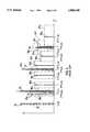
- FIG. 1depicts the essential functional blocks of a prior art oximeter.
- a microprocessor 1controls operation of the oxygen saturation parameter. It generates digitally represented pulses for excitation of the LEDs. These are fed, via line 2, to digital-to-analog converter 3 which outputs analog signals of rectangular shape and feeds them, via line 4, to amplifier 5.
- Dotted line 6represents schematically the interface between the monitor and the sensor. That is, line 7 is physically a cable which connects the sensor and the monitor, and all elements left to dotted line 7 are in practice incorporated into the sensor.
- the sensorcontains at least 2 LEDs 8 and 9 which emit light into the tissue of a patient, here a finger 10. Light transmitted through finger 10 reaches photodiode 11 and is fed, via line 12, to another amplifier 13.
- the amplified analog signal produced by amplifier 13is fed (line 14) to a demodulation and filter section 14.
- This demodulation sectioncomprises a demultiplexer 14a which feeds the amplified signal, depending on its time slot, to three different paths 14b to 14d which implement a low-pass/sample and hold function each.
- Demultiplexer 14ais controlled such that signals received during operation of LED 8 are fed to path 14b, signals received during operation of LED 9 are fed to path 14c, and signals received during the dark or ambient phase (LED's 8 and 9 switched off) are fed to path 14d.
- Each of paths 14b to 14doperates as an independent low-pass filter--see, e.g., resistor 14e and capacitor 14f in path 14b--; the capacitor acts insofar also as a sample and hold device.
- the three paths 14b to 14dare then combined again by multiplexer 14g (which is synchronized with demultiplexer 14a, see dotted line 14h), and the signals are fed to analog-to-digital converter (ADC) 15.
- ADCanalog-to-digital converter
- This ADCsamples the incoming signals, typically once per channel, but a higher sampling rate is also possible. In other words, if a pulse is sent to the red LED 8, it is sensed once by ADC 15 to determine its amplitude, and the variation of the amplitude in succeeding pulse trains reflects pulsatile variation of the arterial blood.
- microprocessor 1which performs the necessary calculations to determine oxygen saturation. The results are then displayed on a display 17.
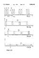
- FIG. 2is a timing diagram of the pulse train used to excite LEDs 8 and 9.
- a first pulse 18controls red LED 8 (FIG. 1), and a second pulse 19 infrared LED 9.
- a dark phase 20is provided which is used on the receiver side to measure the amount of ambient light.
- the modulation frequencyis defined by ##EQU1##
- FIGS. 3a to 3cdepict the same pattern at the receiver side, separated according to paths 14b to 14d (FIG. 1), i.e., when the pulses have passed the human tissue.
- FIG. 3ashows the pulse of the red LED 8 (path 14b),
- FIG. 3bthe pulse of the infrared LED 9 (path 14c), and
- FIG. 3cthe signal detected on path 14d (ambient light).
- the pulse of FIG. 3c which represents ambient lightis not modulated by pulsating tissue (ref. no. 23c).
- the technique discussed herecorresponds to a demodulation with a rectangular or square wave.
- FIG. 4depicts the spectrum of the signal transmitted through the patient's tissue and amplified, but prior to demodulation and sampling, i.e., as it appears on line 14 (FIG. 1).
- the basic LED modulation frequency F LEDis shown as spectral line 24. This is not a "sharp" spectral line. Instead, it is slightly broadened, due to the physiological signal (as discussed above) which in turn modulates the LED signal. The effect is that the LED modulation spectral line appears in fact as a small-band spectrum with a bandwidth of approx. ⁇ 10 Hertz around the center of its base frequency.
- Reference numbers 24a and 24bdesignate harmonics of the basic LED modulation frequency, i.e., 2*f LED and 3*f LED . It is understood that these harmonics appear also broadened by the physiological bandwidth, i.e., they are centered at ⁇ 10 Hertz around the corresponding harmonic frequency.
- reference number 25represents the spectral line of the mains (power line)--at f Line --which is the major source of interference; typically, at 50 Hertz (Europe) or 60 Hertz (United States). It is understood that, although the power line has always a specific frequency, this frequency is subject to variations (however small and slow) of the mains frequency. This variability or tolerance band is indicated by dashed box 25'.
- the spectrumalso contains harmonics of the basic mains frequency f Line . These are denoted as 25a through 25g in FIG. 4 and represent frequencies of 2*f Line to 8*f Line (it will be appreciated that harmonics of even higher order do also exist, but have not been drawn in FIG. 4). Like the basic mains frequency, their harmonics are also spread, see dotted boxes 25a' through 25g'. The diagram shows that the higher the order of the harmonics, the higher the possible variations in frequency.
- FIG. 4reveals also another effect. That is, some of the harmonics of the LED modulation frequency f LED , and of the mains frequency f Line , are quite close to each other. A typical example is shown by reference number 26.
- the received signalis demodulated by demultiplexer 14a.
- This kind of demodulationcorresponds to synchronous AM demodulation with a square wave, as e.g. described in U.S. Pat. No. 4,807,630).
- Demodulation with a square wavehas the effect that all kinds of difference and sum frequencies--in particular, of the harmonics--appear in the base band close to the signal of interest; i.e., the harmonics are folded down into the base band.
- This effectis, by way of example, illustrated in FIG. 5.
- This figureis based on the understanding that the LED sampling frequency is equal to the LED modulation frequency. (Every channel--red, infrared, dark--is separately sampled and demodulated).
- the harmonics of the mains frequencyare only one source of interference which may distort the useful signal for determining oxygen saturation.
- the pulse oximetry sensorpicks up ambient light and various electromagnetic noise.
- the major source for ambient lightis room illumination with fluorescence ceiling lamps which gives broad spectral bands with harmonics at harmonics of the power line frequencies, typically 50 Hertz or 60 Hertz.
- electrical noisealso comes very often from the power line and shows up as harmonics of the mains frequency.
- Other well known sources for largely interfering electrical noiseare electro-surgery devices used in the operating rooms. They can be very broad-band and at any frequency.
- Any noise lines in one of the LED modulation bandswill be demodulated and intrinsically folded down to the base band and contribute to poor signal-to-noise ratios (S/N).
- S/Nsignal-to-noise ratios
- a very dangerous situation for the patientcan occur in the monitoring of neonates. These are often treated with very bright UV lamps for the bilirubin photo therapy. As they produce poor signals because of a poor vascular perfusion, the amount of ambient light can cause even situations with a signal-to-noise ratio ⁇ 1. A pulse oximeter is very likely to be mislead in these situations.
- EP0502717 A1discloses means and methods for evaluating the concentration of a constituent in an object by measuring the transmission of light of two wavelengths therethrough.
- First and second light emittersemit light at respective, first and second different wavelengths.
- a modulator/driverdrives the light emitters with respective first and second carriers which vary as a function of time, the carriers being of the same carrier frequency having a phase difference other than 0 and other than an integer multiple of 180°.
- a detectorreceives light from the first and second light emitters after the same has passed through the object and generates a resulting detector signal carrying information relating to transmission of the object at both wavelengths.
- a first demodulated signal which is a sum of a component proportional to the object's transmission at the first wavelength and one or more carrier modulated componentsis generated by a demodulator from the detector signal in a first channel
- a second demodulated signal which is a sum of a component proportional to the object's transmission at the second wavelength and one or more carrier modulated componentsis generated by the demodulator in a second channel.
- the carrier modulated components of the signalsare filtered out of the first and second channels by a demodulated signal filter.
- the demodulatormultiplies the detector signal in the first channel with a sinusoidal signal in phase with the first carrier to generate the first demodulated signal, and multiplies the detector signal in the second channel with a sinusoidal signal in phase with the second carrier to generate the second demodulated signal. Therefore, in accordance with the disclosure of EP 0502717 A1, the sinusoidal signal for demodulating the detector signals in the first and the second channel are in phase with the first carrier and the second carrier, respectively.
- This demodulation methodis disadvantageously to the effect that there exists a cross-talking between the first and the second channels, and therefore no accurate evaluation of the concentration of a constituent in an object is possible.
- the present inventionis based on the perception that in prior art analysis systems for measuring medical parameters, for example the system that is disclosed in EP 0502717 A1, an accurate measurement and subsequent analysis of medical parameters is impossible due to a phase shift which is introduced by the system between the electromagnetic waves which are used to irradiate a sample and the electromagnetic waves which are used for analysis. Therefore, the present invention provides methods and apparatus for measuring medical parameters of a patient by irradiation of electromagnetic waves into a sample and for measurement and subsequent analysis of the electromagnetic waves which have passed through said sample, wherein the system phase shift is compensated during the analysis of the received electromagnetic waves.
- the above objectis achieved by a method for measuring medical parameters of a patient by irridation of electro-magnetic waves into a sample and for measurement and subsequent analysis of the electromagnetic waves which have passed through said sample, said method comprising the steps of:
- demodulating signals repesentative of the received electromagnetic wavesby multiplying the same with a first sinusoidal demodulation signal and with a second sinusoidal demodulation signal having the first phase difference with respect to said first sinusoidal signal, said first and second sinusoidal demodulation signals having the same frequency as said first and second modulation signals, such as to generate a first and a second demodulated signal;
- first and the second sinusoidal demodulation signalshave a phase difference relative to the first and second modulation signals corresponding to a system phase shift
- the first and second sinusoidal demodulation signalscomprise a phase difference relative to the first and second modulation signals which corresponds to the system phase shift, whereby the influence of the system phase shift on the result of the analysis is eliminated and therefore a cross-talking between channels is reduced.
- the above objectis achieved by a method for measuring medical parameters of a patient by irridation of electromagnetic waves into a sample and for measurement and subsequent analysis of the electromagnetic waves which have passed through said sample, said method comprising the steps of:
- demodulating signals repesentative of the received electromagnetic wavesby multiplying the same with a first sinusoidal demodulation signal and with a second sinusoidal demodulation signal having the first phase difference with respect to said first sinusoidal signal, said first and second sinusoidal demodulation signals having the same frequency as said first and second modulation signals, such as to generate a first and a second demodulated signal;
- demodulating signals of received electromagnetic wavesare demodulated by sinusoidal demodulation signals to generate a first and a second demodulated signal.
- These first and second demodulated signalsare analysed, for example by a microprocessor, under consideration of a system phase shift.
- a correction matrixis calculated which is used to correct the demodulated signals in order to eliminate the influence of the system phase shift on the result of the analysis.
- the influence of the system phase shift on the result of the analysiscan be eliminated by software, for example in the central processing unit of the system.
- the above objectis achieved by a method for measuring medical parameters of a patient by irridation of electromagnetic waves into a sample and for measurement and subsequent analysis of the electromagnetic waves which have passed through said sample, said method comprising the steps of:
- demodulating signals representative of the delayed received electromagnetic wavesby multiplying the same with a first sinusoidal demodulation signal and with a second sinusoidal demodulation signal having the first phase difference with respect to said first sinusoidal signal, said first and second sinusoidal demodulation signals having the same frequency as said first and second modulation signals, such as to generate a first and a second demodulated signal;
- the influence of the system phase shift on the result of the analysisis eliminated by adding a phase shift to the received electromagnetic waves, such that a total phase shift of the received electromagnetic waves relative to transmitted electromagnetic waves is substantially an integral multiple of 360°.
- This total phase shift of an integral multiple of 360°makes sure that a cross-talking between channels of the received electromagnetic waves is reduced.
- an apparatus for measuring medical parameters of a patient by irridation of electromagnetic waves into a sample and for measurement and subsequent analysis of the electromagnetic waves which have passed through said samplecomprising:
- first and the second sinusoidal demodulation signalshave a phase difference relative to the first and second modulation signals corresponding to a system phase shift
- the above objectis achieved by an apparatus for measuring medical parameters of a patient by irridation of electromagnetic waves into a sample and for measurement and subsequent analysis of the electromagnetic waves which have passed through said sample, said method comprising the steps of:
- an apparatus for measuring medical parameters of a patient by irridation of electromagnetic waves into a sample and for measurement and subsequent analysis of the electromagnetic waves which have passed through said samplecomprising:
- the modulation signalsthemselves may be sine waves, in which case the mathematical theory becomes particularly easy. However, square or rectangular waves may be used as well. Square waves are easy to generate and have another related advantage: That is, the duty cycle may be easily varied without changing the fundamental frequency, in order to adapt the signal strength in various channels. (The shape of the modulation signals should not be mixed up with the signals used for demodulation; according to the invention, the latter have always to be sinusoidal signals).
- a low pass filteris provided through which the output signal of the multiplier circuit is fed.
- a bandfilterconnected between the receiver of the electromagnetic waves and the demodulator. This bandfilter blocks the harmonics, and even the fundamental frequencies of any noise, and further operates as an anti-aliasing filter for subsequent analog-to-digital conversion.
- the biological material examined in vivois the patient's tissue.
- the electromagnetic wavesare preferably waves selected from the visible and the adjoining spectra of light, in particular red and/or infrared light.
- the emitters of lightare advantageously light-emitting diodes which are of small size and easy to incorporate into a sensor.
- FIG. 1depicts a block diagram of a prior art oximeter
- FIG. 2is a timing diagram of the pulse train emitted by a prior art oximeter
- FIGS. 3a to 3care timing diagrams of the pulse trains received by a prior art oximeter
- FIG. 4is the spectrum of a prior art time multiplex oximeter prior to demodulation
- FIG. 5depicts the effect of demodulation on the spectrum in prior art oximeters
- FIG. 6is a block diagram of a pulse oximeter according to the present invention.
- FIG. 7depicts the shape and timing of the pulses used to control the light-emitting diodes
- FIG. 8is a block diagram of the digital signal processor
- FIG. 9is an example of a spectrum processed by an apparatus according to the present invention.
- FIG. 10shows the effect of the quadrature modulation technique according to the present invention on the signal-to-noise improvements
- FIG. 11 and FIG. 12are vector diagrams for illustrating phase shift measurements
- FIG. 13is a schematic representation for illustrating direct phase measurement on an unfiltered signal.
- FIGS. 1 through 5 illustrating the prior art approachhave already been discussed above, such that there is no need to consider them further.
- FIG. 6depicts a block diagram of a two-wavelength pulse oximeter according to the invention.
- a microcontroller or CPU (central processing unit) 28controls overall operation of the oximeter. In particular, it starts the measurements, adjusts the gain and controls the timing of LED excitation. Further, most of the signal processing, in particular calculation of the pulse oximetry values (oxygen saturation), of the pulse rate, the perfusion indicator and plethysmograhic waveforms is performed by CPU 28. Such algorithms--specifically suited for artifact suppression are, for example, described in another patent, U.S. Pat. No. 5,299,120, originating from the inventor of the present case.
- CPU 28may further communicate with other equipment, such as a host monitor 29, via a digital link 30. The host monitor is equipped with data and waveform display capabilities, controls the alarm limits etc. It is, however, understood that the display of data, manual input etc. could also be performed locally. Further, CPU 28 may even communicate with larger systems such as hospital information systems or central stations.
- the control signals for driving, i.e., for switching the LEDsare fed from CPU 28, via line 31, to an LED driver circuit 32 (the digital-to-analog converter is not shown here and may be integrated in CPU 28).
- LED driver circuit 32contains current sources which operate light emitting diodes (LEDs) 33 and 34 in switched mode.
- a red LEDis designated as 33, and an infrared LED as 34. Both LEDs, as well as a photodiode 35, are integrated into an appropriate sensor. Such sensors are well-known in the art and need not be discussed in detail here. Reference is made, for example, to DE-C-37 03 458. The rest of the elements shown in FIG. 6 are not incorporated in the sensor, but in an appropriate monitor, a signal pick-up box or the like.
- LED driver circuit 32operates LEDs 33 and 34 in antiparallel mode. That is, red LED 33 is operated by pulses of one polarity, and infrared LED 34 is operated by pulses of the opposite polarity. This design requires less connections between the sensor and the associated monitor, although it is not a necessary prerequisite for practising the present invention.
- these pulsesare of rectangular shape, although they could also be shaped as a sine, or incorporate any other suitable shape.
- the pulse driving the red LED 33is designated as 36.
- Another pulse 37(of opposite polarity, not shown in FIG. 7) drives infrared LED 34.
- An important design feature of the timing chosen in the pulse oximeter according to the inventionis that the pulses of the red and the infrared LED, respectively, are offset by 90°, see reference number 38. (In terms of timing, this phase shift corresponds to T LED /4).
- the reference lines for the 90° phase shiftare the center of the red and infrared pulse, respectively. This is of importance if a duty cycle adjustment is necessary or desirable to balance the red and infrared signals.
- Such duty cycle adjustmentmeans to adapt the pulse length of either or both of the pulses, as indicated by arrows 39a to 39d.
- the light pulses generated by LEDs 33 and 34pass human tissue, as indicated by a finger 40, and are received by photodiode 35.
- the output signal of the photodiodeis fed to a photo amplifier 41.
- This photo amplifierconverts the photo current of the photodiode into a voltage.
- its bandwidthcan be limited to f FLED in the present invention. Its gain is selected as high as possible, but within the limits of the maximum expected photo currents.
- Reference number 42designates a band filter.
- the main purpose of that stageis to block out-of-the band noise and to serve as an anti-aliasing filter for analog-to-digital sampling.
- the passbandis designed as narrow as possible around the center frequency f LED .
- the bandwidthis only slightly broader than the bandwidth of the physiological blood pulse signal. Any harmonics of the LED sampling frequency can be blocked out as they do not contribute to the demodulated signal.
- Programmable gain amplifier 43(controlled by CPU 28, see line 44) ensures that the filtered signal fits within the input range of analog-to-digital converter (ADC) 45. It is therefore used to adapt to the large dynamic variability of the photoelectrical signal. As pulse oximetry sensors are used on very different body locations, the different tissue types and thickness between emitters and receivers result in largely different light intensities.
- the gain of that amplifieris controlled by the CPU to adapt the output amplitude to fit the full scale input range of the analog-to-digital converter for good quantization.
- Digital signal processor (DSP) 46represents, to some extent, the "heart" of the present invention. It demodulates the received, filtered and digitized pulses with sinusoidal functions. In the shown embodiment, this demodulation is performed in the digital domain--i.e., by a digital processor--, and in fact the functionality of DSP 46 may be provided by CPU 28 as well. However, this is not a necessary requirement; DSP 46 may also be a separate signal processor in digital or analog technology. The major functions of DSP 46 are demodulation, low pass filtering and down sampling.
- DSP 46In order to explain the functionality provided by DSP 46, reference is now made to FIG. 8.
- the output signal of ADC 45, A(t),is fed to two multipliers 47 and 48, which perform a multiplication with sinusoidal functions sin( ⁇ LED t) and cos( ⁇ LED t), respecitvely.
- the demodulated signalsare now fed, via lines 49 and 50, to respective digital low pass filters 51 and 52. Their functionality will be discussed in greater detail below.
- the LEDsare driven so that the optical emissions of the LEDs are pure sine waves, shifted by 90° in phase, e.g. the red LED with a sine and the infrared LED with a cosine.
- thisis not the case, as shown above; however, the mathematical background may be explained more easily by the assumption of sinusoidal driving.
- ADC 45i.e., the input signal to DSP 46 is then
- a R and A IRthemselves are modulated by the patient's blood pulse:
- S R (t) and S IR (t)are composed of a DC and an AC component.
- the DC componentrepresents the constant tissue absorption, whereas the AC component is related to the variable absorbance due to pulsatile blood volume change).
- the CPUis programmed to determine the system phase shift ⁇ in order to make the demodulator phase shift ⁇ equal to the system phase shift ⁇ .
- the demodulated signalscontain both the sum and difference frequencies. These signals are then fed through digital low pass filters 51 and 52 which have a cut-off frequency just beyond the physiological bandwidth of the blood pulse. In an ideal low pass filter, this operation cuts off all harmonics of the modulation frequency f LED .
- signals A R and A IRare not constant, but are modulated by the blood pulsation itself.
- L R (t) and L IR (t)are now small-band signals, which means that the data rate is reduced to a level desirable by standard down-sampling techniques. It is further understood that all other frequencies in the received signal, like electrical or optical interference, are blocked completely by the method according to the present invention. The result is very pure, noise-free signal reconstruction. Therefore fore, it is possible to choose an interference-free modulation band, even at lowest frequencies.
- FIG. 9This figures depicts a typical spectrum in a representation similar to FIG. 4. However, FIG. 9 depicts even a more sensitive case, just because some of the harmonics of the LED modulation frequency, and some harmonics of the mains frequency coincide. Reference numbers 53 and 54 relate to such cases:
- the demodulation technique according to the present inventionis, however, still able to filter the harmonics of the mains frequency out, as will now be shown by means of FIG. 10.
- the quadrature demodulation techniquein combination with sampling, produces a shift of the related spectra, together with the generation of sum and difference frequencies.
- the amount of frequency shiftis f demod , i.e., the frequency of the sine functions used for demodulation, which is in this case identical to the LED modulation frequency f LED .
- the shifted spectra(two in total) are shown in FIG. 10, namely the spectrum shifted by +f demod (upper diagram) and the spectrum shifted by -f demod (second diagram from top). (The frequency designations are, except of the shift, identical in both diagrams, so they are only shown in the upper one).
- the resulting spectrumis shown in the lower diagram.
- a low passfilters out the base band and blocks all higher frequencies (its attenuation characteristics is designated by reference number 55).
- the baseband signaldoes not contain any noise resulting from the harmonics of the power line or other sources of interference, which makes up the great advantage of the present invention over the prior art approach.
- the system phase shift ⁇ of the systemis determined, and on the basis of the determined system phase shift ⁇ the phase shift ⁇ of the sinusoidal demodulation signals with respect to the first and second modulation signals is adjusted.
- phase shift ⁇is defined as the phase difference between the excitation signals which drive each LED and the receiving signal as sampled by the A/D converter.
- a software routine in the CPUperforms that measurement routinely at power up and selected events during normal operation. Events can be programmed time intervals, a change of the sensor connected, changing the gain of programmable gain amplifier, and thereby its filter characteristics, and so on.
- the normal operating modeis interrupted.
- the red LEDis disabled, whereas the infrared LED is driven in its normal mode.
- a default phase ⁇ equal ⁇ DEFis applied to the demodulator.
- the real-time values in the red channel L R ' and the infrared channel L IR 'are stored.
- the correct phase shift ⁇ to be applied to the demodulatoris calculated, see the following equation.
- the correct phase shift ⁇is applied to the demodulator.
- the red LEDis enabled again. After having awaited until low pass filters have settled again, the normal operating mode is resumed.
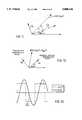
- the arrow designated by L' IRrepresents the infrared demodulation vector.
- the value of the demodulated signal in the red channelwould be close to 0, if the default phase ( ⁇ DEF ) was already correct.
- a cross-talk L R ' from the infrared exitationexists because the default phase (or the phase from a prior adjustment) is only close to the correct value, that means the correction angle ⁇ 0.
- the vector diagram shown in FIG. 12shows the situation after having applied the phase adjustment.
- the arrow on the left hand side L Rrepresents the adjusted red demodulation vector.
- the arrow on the right hand side L IRrepresents the adjusted infrared demodulation vector.
- the middle arrowrepresents the received electromagnetic waves A(t) being a combination of the electromagnetic wave A R (t) (red excitation) and the electromagnetic wave A IR (t) (infrared excitation).
- the correct phase shift a to be applied to the demodulatorcorresponds to the system phase shift ⁇ .
- This auto-phase-adjustis that it compensates for any phase shifts and drifts which can occur for reason of temperature, aging and component tolerances. It also adapts to changing sensor characteristics.
- a further advantage of this implementation of automatic adjustis that it can be applied without interruption of the continuous plethysmographic wave form, if the pleth signal is derived from the infrared LED.
- C! -1is the inverse matrix of C!.
- the normal operating modeis interrupted, the red LED is disabled and the infrared LED is continuously driven in normal mode.
- real-time values in the "red" channel L R ' and the "infrared" channel L IR 'are stored.
- the system phase shift ⁇is calculated on the basis of equation (13).
- the red LEDis enabled again, and after a waiting time, until low-pass filters have settled, the normal operating mode is resumed.
- the normal operating mode in this casemeans applying equation (21) with the previously determined phase shift ⁇ .
- the correction calculation described abovecan be performed for example by the CPU 28.
- Another method to overcome signal cross-coupling between "red” and “infrared” channels in accordance with the present inventionis to use an all-pass filter anywhere in the signal path between photoreceiver and demodulator.
- the all-pass filterhas the function of a phase shifter. This all-pass filter should have a phase shift ⁇ at the excitation base frequency f LED which yields to:
- phase measurement procedurewould be as follows.
- the normal operating modeis interrupted, the red LED is disabled, the infrared LED is continuously driven, and the all-pass function is switched off (by-pass etc.). Thereafter, there is a waiting time for some milliseconds until the low-pass filters have settled. After this waiting time, the real-time values in the "red" channel L R' and the "infrared” channel L IR ', are stored. On the basis of these stored values and equation (13) the system phase shift ⁇ is calculated.
- the phase shift ⁇ which the all-pass filter should haveis determined according equation (22).
- the appropriate filter constants for this type of all-pass filterare selected.
- the normal operating modein this case means activating the all-pass function in the signal flow with the determined characteristics in order to produce a phase shift ⁇ of the received electromagnetic waves in the signal path between photoreceiver and modulator.
- a further method to determine the system phase shift ⁇is described.
- the difference in the zero-crossing between the incoming signal A(t) and the LED drive signal J R (t) and J IR (t)is measured before demodulation, rather than measuring the amplitudes of the incoming signals on the low-pass filtered side.
- the incoming signal A(t)is shown as a sinusoidal wave form.
- the "infrared" excitation waveis shown as a quare waveform J IR (t).
- the phase difference ⁇ of this two waveforms which corresponds to the system phase shift ⁇is determined on the basis of a negative zero-crossing of both these signals.
- the phase shift determined by this methodcan be used in the same way as the phase shift determined on the basis of equation (13).
- sinusoidal demodulationcan be applied in a two LED pulse oximeter without the quadrature concept, but with only the sinusoidal demodulation, if there is a different modulation frequency chosen for each LED.
- interference immunity of this systemmay also be applied to other sensoric measurements where ambient noise is an issue, not only in medical instrumentation. It is always possible where an excitation is used for stimulation. Examples are impedance measurements in bridges like pressure strain gauges or spectrometer devices with chopped sources.
Landscapes
- Physics & Mathematics (AREA)
- Health & Medical Sciences (AREA)
- Spectroscopy & Molecular Physics (AREA)
- Life Sciences & Earth Sciences (AREA)
- General Health & Medical Sciences (AREA)
- Pathology (AREA)
- Optics & Photonics (AREA)
- Biomedical Technology (AREA)
- Analytical Chemistry (AREA)
- General Physics & Mathematics (AREA)
- Immunology (AREA)
- Chemical & Material Sciences (AREA)
- Toxicology (AREA)
- Biophysics (AREA)
- Engineering & Computer Science (AREA)
- Biochemistry (AREA)
- Heart & Thoracic Surgery (AREA)
- Medical Informatics (AREA)
- Molecular Biology (AREA)
- Surgery (AREA)
- Animal Behavior & Ethology (AREA)
- Public Health (AREA)
- Veterinary Medicine (AREA)
- Measurement Of The Respiration, Hearing Ability, Form, And Blood Characteristics Of Living Organisms (AREA)
Abstract
Description
A(t)=A.sub.R (t)+A.sub.IR (t) (2)
A.sub.R (t)=A.sub.R *sin (2π*f.sub.LED *t+φ) (3a)
A.sub.IR (t)=A.sub.IR *cos (2π*f.sub.LED *t+φ) (3b)
A.sub.R =S.sub.R (t) (4a)
A.sub.IR =S.sub.IR (t) (4b)
D.sub.R (t)=A(t)*M.sub.R (t) (5a)
D.sub.IR (t)=A(t)*M.sub.IR (t) (5b)
M.sub.R (t)=sin (ω.sub.LED *t+σ) (5c)
D.sub.IR (t)=cos (ω.sub.LED *t+σ) (5d)
D.sub.R (t)=1/2A.sub.R -1/2A.sub.R *cos (2ω.sub.LED *t+2φ)+1/2A.sub.IR *sin (2ω.sub.LED *t+2φ) (6a)
D.sub.IR (t)=1/2A.sub.IR -1/2A.sub.IR *cos (2ω.sub.LED *t+2φ)+1/2A.sub.R *sin (2ω.sub.LED *t2φ) (6b)
L.sub.R (t)=1/2A.sub.R (7a)
L.sub.IR (t)=1/2A.sub.IR (7b)
2*f.sub.LED ≈3*f.sub.Line (Ref. no. 53) (8a)
4*f.sub.LED ≈6*ff.sub.Line (Ref. no. 54) (8b)
D.sub.R (t)=1/2A.sub.R cos (φ)-cos (2ω.sub.LED *t+σ)!+1/2A.sub.IR sin (-φ)*sin (2ω.sub.LED *t+σ)!(14a)
D.sub.IR (t)=1/2A.sub.R sin (φ)+sin (2ω.sub.LED *t+σ)!+1/2A.sub.IR cos (φ)*cos (2ω.sub.LED *t+σ)!(15a)
D.sub.R (t)=1/2A.sub.R cos (φ)-cos (2ω.sub.LED *t)!+1/2A.sub.IR sin (-φ)*sin (2ω.sub.LED *t)! (14b)
D.sub.IR (t)=1/2A.sub.R sin (φ)+sin (2ω.sub.LED *t)!+1/2A.sub.IR cos (φ)*cos (2ω.sub.LED *t)! (15b)
L.sub.R (t)=1/2A.sub.R *cos (φ)+1/2A.sub.IR *sin (-φ)(16)
L.sub.IR (t)=1/2A.sub.R *sin (φ)+1/2A.sub.IR *cos (φ)(17)
A!= C!.sup.-1 · L! (12)
δ+φ=n*360° (22)
Claims (77)
Priority Applications (1)
| Application Number | Priority Date | Filing Date | Title |
|---|---|---|---|
| US08/710,794US5800348A (en) | 1995-08-31 | 1996-09-23 | Apparatus and method for medical monitoring, in particular pulse oximeter |
Applications Claiming Priority (6)
| Application Number | Priority Date | Filing Date | Title |
|---|---|---|---|
| EP95113654AEP0760223A1 (en) | 1995-08-31 | 1995-08-31 | Apparatus for monitoring, in particular pulse oximeter |
| EP95113654 | 1995-08-31 | ||
| US56587995A | 1995-12-01 | 1995-12-01 | |
| EP19960112658EP0761159B1 (en) | 1995-08-31 | 1996-08-06 | Apparatus for medical monitoring, in particular pulse oximeter |
| EP96112658 | 1996-08-06 | ||
| US08/710,794US5800348A (en) | 1995-08-31 | 1996-09-23 | Apparatus and method for medical monitoring, in particular pulse oximeter |
Related Parent Applications (1)
| Application Number | Title | Priority Date | Filing Date |
|---|---|---|---|
| US56587995AContinuation-In-Part | 1995-08-31 | 1995-12-01 |
Publications (1)
| Publication Number | Publication Date |
|---|---|
| US5800348Atrue US5800348A (en) | 1998-09-01 |
Family
ID=27236581
Family Applications (1)
| Application Number | Title | Priority Date | Filing Date |
|---|---|---|---|
| US08/710,794Expired - LifetimeUS5800348A (en) | 1995-08-31 | 1996-09-23 | Apparatus and method for medical monitoring, in particular pulse oximeter |
Country Status (1)
| Country | Link |
|---|---|
| US (1) | US5800348A (en) |
Cited By (132)
| Publication number | Priority date | Publication date | Assignee | Title |
|---|---|---|---|---|
| US5995858A (en)* | 1997-11-07 | 1999-11-30 | Datascope Investment Corp. | Pulse oximeter |
| US6101404A (en)* | 1996-05-23 | 2000-08-08 | Samsung Electronics Co., Ltd. | Optical diagnosis point detector for noninvasive diagnosis of blood constituents and noninvasive diagnostic device |
| WO2001044781A3 (en)* | 1999-12-17 | 2001-12-13 | Datex Ohmeda Inc | Oversampling pulse oximeter |
| WO2001044780A3 (en)* | 1999-12-17 | 2002-01-03 | Datex Ohmeda Inc | Synchronized modulation/demodulation method and apparatus for frequency division multiplexed spectrophotometric system |
| US20020027649A1 (en)* | 2000-07-08 | 2002-03-07 | Victor Chudner | Method for blood infrared spectroscopy diagnosing of inner organs pathology |
| US6393311B1 (en) | 1998-10-15 | 2002-05-21 | Ntc Technology Inc. | Method, apparatus and system for removing motion artifacts from measurements of bodily parameters |
| US6505133B1 (en) | 2000-11-15 | 2003-01-07 | Datex-Ohmeda, Inc. | Simultaneous signal attenuation measurements utilizing code division multiplexing |
| US6519486B1 (en) | 1998-10-15 | 2003-02-11 | Ntc Technology Inc. | Method, apparatus and system for removing motion artifacts from measurements of bodily parameters |
| FR2830325A1 (en)* | 2001-09-28 | 2003-04-04 | Centre Nat Rech Scient | DEVICE FOR MEASURING THE LIGHT ABSORPTION CHARACTERISTICS OF A BIOLOGICAL TISSUE SAMPLE, ASSOCIATED MEASUREMENT METHOD, AND APPLICATIONS IN THE FIELD OF PLANT ANALYSIS AND THE MEDICAL FIELD |
| US20030114737A1 (en)* | 2001-11-20 | 2003-06-19 | Minolta Co., Ltd. | Blood component measurement apparatus |
| US6597439B1 (en)* | 1999-02-12 | 2003-07-22 | Fuji Photo Film Co., Ltd. | Method and apparatus for measurement of light from illuminated specimen eliminating influence of background light |
| US20030236647A1 (en)* | 2002-03-16 | 2003-12-25 | Yoon Gil-Won | Diagnostic method and apparatus using light |
| US20040152965A1 (en)* | 1997-04-14 | 2004-08-05 | Diab Mohamed K. | Method and apparatus for demodulating signals in a pulse oximetry system |
| US20050049468A1 (en)* | 2003-09-03 | 2005-03-03 | Sven-Erik Carlson | Increasing the performance of an optical pulsoximeter |
| US20050187451A1 (en)* | 2004-02-25 | 2005-08-25 | Norris Mark A. | Simultaneous signal attenuation measurements utilizing frequency orthogonal random codes |
| US6970738B1 (en) | 2002-02-04 | 2005-11-29 | Innovamedica S.A. De C.V. | Complex impedance spectrometer using parallel demodulation and digital conversion |
| WO2006094108A1 (en)* | 2005-03-01 | 2006-09-08 | Masimo Laboratories, Inc. | Multiple wavelength sensor equalization |
| US20060258927A1 (en)* | 1998-10-15 | 2006-11-16 | Edgar Reuben W Jr | Method, apparatus, and system for removing motion artifacts from measurements of bodily parameters |
| US20080033266A1 (en)* | 1994-10-07 | 2008-02-07 | Diab Mohamed K | Signal processing apparatus |
| WO2008029171A3 (en)* | 2006-09-08 | 2008-05-02 | Crowcon Detection Instr Ltd | Gas detector |
| US20080125664A1 (en)* | 2006-11-27 | 2008-05-29 | Denso Corporation | Pulse wave detection apparatus |
| EP1987442A2 (en)* | 2006-02-20 | 2008-11-05 | Fraunhofer-Gesellschaft zur Förderung der angewandten Forschung e.V. | Adaptive filtering for determining vital parameters more reliably |
| US7477924B2 (en) | 2006-05-02 | 2009-01-13 | Nellcor Puritan Bennett Llc | Medical sensor and technique for using the same |
| US7483731B2 (en) | 2005-09-30 | 2009-01-27 | Nellcor Puritan Bennett Llc | Medical sensor and technique for using the same |
| US7486979B2 (en) | 2005-09-30 | 2009-02-03 | Nellcor Puritan Bennett Llc | Optically aligned pulse oximetry sensor and technique for using the same |
| US7489958B2 (en) | 1997-04-14 | 2009-02-10 | Masimo Corporation | Signal processing apparatus and method |
| US7499740B2 (en) | 2004-02-25 | 2009-03-03 | Nellcor Puritan Bennett Llc | Techniques for detecting heart pulses and reducing power consumption in sensors |
| US7509154B2 (en) | 1991-03-07 | 2009-03-24 | Masimo Corporation | Signal processing apparatus |
| US7522948B2 (en) | 2006-05-02 | 2009-04-21 | Nellcor Puritan Bennett Llc | Medical sensor and technique for using the same |
| US7555327B2 (en) | 2005-09-30 | 2009-06-30 | Nellcor Puritan Bennett Llc | Folding medical sensor and technique for using the same |
| US7574245B2 (en) | 2006-09-27 | 2009-08-11 | Nellcor Puritan Bennett Llc | Flexible medical sensor enclosure |
| US7574244B2 (en) | 2005-08-08 | 2009-08-11 | Nellcor Puritan Bennett Llc | Compliant diaphragm medical sensor and technique for using the same |
| US7590439B2 (en) | 2005-08-08 | 2009-09-15 | Nellcor Puritan Bennett Llc | Bi-stable medical sensor and technique for using the same |
| EP1420242A4 (en)* | 2001-07-19 | 2009-11-11 | Hitachi Medical Corp | Biological optical measuring instrument |
| US7650177B2 (en) | 2005-09-29 | 2010-01-19 | Nellcor Puritan Bennett Llc | Medical sensor for reducing motion artifacts and technique for using the same |
| US7657295B2 (en) | 2005-08-08 | 2010-02-02 | Nellcor Puritan Bennett Llc | Medical sensor and technique for using the same |
| US7658652B2 (en) | 2006-09-29 | 2010-02-09 | Nellcor Puritan Bennett Llc | Device and method for reducing crosstalk |
| US7676253B2 (en) | 2005-09-29 | 2010-03-09 | Nellcor Puritan Bennett Llc | Medical sensor and technique for using the same |
| US7680522B2 (en) | 2006-09-29 | 2010-03-16 | Nellcor Puritan Bennett Llc | Method and apparatus for detecting misapplied sensors |
| US20100070550A1 (en)* | 2008-09-12 | 2010-03-18 | Cardinal Health 209 Inc. | Method and apparatus of a sensor amplifier configured for use in medical applications |
| US7684842B2 (en) | 2006-09-29 | 2010-03-23 | Nellcor Puritan Bennett Llc | System and method for preventing sensor misuse |
| US7689259B2 (en) | 2000-04-17 | 2010-03-30 | Nellcor Puritan Bennett Llc | Pulse oximeter sensor with piece-wise function |
| US7740589B2 (en) | 2003-07-21 | 2010-06-22 | Siemens Aktiengesellschaft | Method and apparatus for training adjustment in sports, in particular in running sports |
| US7796403B2 (en) | 2006-09-28 | 2010-09-14 | Nellcor Puritan Bennett Llc | Means for mechanical registration and mechanical-electrical coupling of a faraday shield to a photodetector and an electrical circuit |
| US7869849B2 (en) | 2006-09-26 | 2011-01-11 | Nellcor Puritan Bennett Llc | Opaque, electrically nonconductive region on a medical sensor |
| US7880884B2 (en) | 2008-06-30 | 2011-02-01 | Nellcor Puritan Bennett Llc | System and method for coating and shielding electronic sensor components |
| US7881762B2 (en) | 2005-09-30 | 2011-02-01 | Nellcor Puritan Bennett Llc | Clip-style medical sensor and technique for using the same |
| US7887345B2 (en) | 2008-06-30 | 2011-02-15 | Nellcor Puritan Bennett Llc | Single use connector for pulse oximetry sensors |
| US7890153B2 (en) | 2006-09-28 | 2011-02-15 | Nellcor Puritan Bennett Llc | System and method for mitigating interference in pulse oximetry |
| US7894869B2 (en) | 2007-03-09 | 2011-02-22 | Nellcor Puritan Bennett Llc | Multiple configuration medical sensor and technique for using the same |
| US7899510B2 (en) | 2005-09-29 | 2011-03-01 | Nellcor Puritan Bennett Llc | Medical sensor and technique for using the same |
| US20110098543A1 (en)* | 2003-07-08 | 2011-04-28 | Masimo Laboratories, Inc | Method and apparatus for reducing coupling between signals in a measurement system |
| US7937130B2 (en) | 1991-03-07 | 2011-05-03 | Masimo Corporation | Signal processing apparatus |
| WO2011123239A1 (en)* | 2010-03-31 | 2011-10-06 | Nellcor Puritan Bennett Llc | Multi-wavelength photon density wave system using an optical switch |
| US8062221B2 (en) | 2005-09-30 | 2011-11-22 | Nellcor Puritan Bennett Llc | Sensor for tissue gas detection and technique for using the same |
| US8068891B2 (en) | 2006-09-29 | 2011-11-29 | Nellcor Puritan Bennett Llc | Symmetric LED array for pulse oximetry |
| US8070508B2 (en) | 2007-12-31 | 2011-12-06 | Nellcor Puritan Bennett Llc | Method and apparatus for aligning and securing a cable strain relief |
| US8073518B2 (en) | 2006-05-02 | 2011-12-06 | Nellcor Puritan Bennett Llc | Clip-style medical sensor and technique for using the same |
| US8071935B2 (en) | 2008-06-30 | 2011-12-06 | Nellcor Puritan Bennett Llc | Optical detector with an overmolded faraday shield |
| US8092379B2 (en) | 2005-09-29 | 2012-01-10 | Nellcor Puritan Bennett Llc | Method and system for determining when to reposition a physiological sensor |
| US8092993B2 (en) | 2007-12-31 | 2012-01-10 | Nellcor Puritan Bennett Llc | Hydrogel thin film for use as a biosensor |
| US8112375B2 (en) | 2008-03-31 | 2012-02-07 | Nellcor Puritan Bennett Llc | Wavelength selection and outlier detection in reduced rank linear models |
| US8133176B2 (en) | 1999-04-14 | 2012-03-13 | Tyco Healthcare Group Lp | Method and circuit for indicating quality and accuracy of physiological measurements |
| US8145288B2 (en) | 2006-08-22 | 2012-03-27 | Nellcor Puritan Bennett Llc | Medical sensor for reducing signal artifacts and technique for using the same |
| US8175671B2 (en) | 2006-09-22 | 2012-05-08 | Nellcor Puritan Bennett Llc | Medical sensor for reducing signal artifacts and technique for using the same |
| US8175667B2 (en) | 2006-09-29 | 2012-05-08 | Nellcor Puritan Bennett Llc | Symmetric LED array for pulse oximetry |
| US8190224B2 (en) | 2006-09-22 | 2012-05-29 | Nellcor Puritan Bennett Llc | Medical sensor for reducing signal artifacts and technique for using the same |
| US8199007B2 (en) | 2007-12-31 | 2012-06-12 | Nellcor Puritan Bennett Llc | Flex circuit snap track for a biometric sensor |
| US8219170B2 (en) | 2006-09-20 | 2012-07-10 | Nellcor Puritan Bennett Llc | System and method for practicing spectrophotometry using light emitting nanostructure devices |
| US8221319B2 (en) | 2009-03-25 | 2012-07-17 | Nellcor Puritan Bennett Llc | Medical device for assessing intravascular blood volume and technique for using the same |
| US8224412B2 (en) | 2000-04-17 | 2012-07-17 | Nellcor Puritan Bennett Llc | Pulse oximeter sensor with piece-wise function |
| US8233954B2 (en) | 2005-09-30 | 2012-07-31 | Nellcor Puritan Bennett Llc | Mucosal sensor for the assessment of tissue and blood constituents and technique for using the same |
| US20120212744A1 (en)* | 2011-02-21 | 2012-08-23 | Yokogawa Electric Corporation | Laser gas analyzer |
| US8260391B2 (en) | 2005-09-12 | 2012-09-04 | Nellcor Puritan Bennett Llc | Medical sensor for reducing motion artifacts and technique for using the same |
| US8265724B2 (en) | 2007-03-09 | 2012-09-11 | Nellcor Puritan Bennett Llc | Cancellation of light shunting |
| US8280469B2 (en) | 2007-03-09 | 2012-10-02 | Nellcor Puritan Bennett Llc | Method for detection of aberrant tissue spectra |
| US8311601B2 (en) | 2009-06-30 | 2012-11-13 | Nellcor Puritan Bennett Llc | Reflectance and/or transmissive pulse oximeter |
| US8346328B2 (en) | 2007-12-21 | 2013-01-01 | Covidien Lp | Medical sensor and technique for using the same |
| US8352004B2 (en) | 2007-12-21 | 2013-01-08 | Covidien Lp | Medical sensor and technique for using the same |
| US8364220B2 (en) | 2008-09-25 | 2013-01-29 | Covidien Lp | Medical sensor and technique for using the same |
| US8366613B2 (en) | 2007-12-26 | 2013-02-05 | Covidien Lp | LED drive circuit for pulse oximetry and method for using same |
| US8391941B2 (en) | 2009-07-17 | 2013-03-05 | Covidien Lp | System and method for memory switching for multiple configuration medical sensor |
| US8396527B2 (en) | 2006-09-22 | 2013-03-12 | Covidien Lp | Medical sensor for reducing signal artifacts and technique for using the same |
| US8417310B2 (en) | 2009-08-10 | 2013-04-09 | Covidien Lp | Digital switching in multi-site sensor |
| US8417309B2 (en) | 2008-09-30 | 2013-04-09 | Covidien Lp | Medical sensor |
| US8423112B2 (en) | 2008-09-30 | 2013-04-16 | Covidien Lp | Medical sensor and technique for using the same |
| US8428675B2 (en) | 2009-08-19 | 2013-04-23 | Covidien Lp | Nanofiber adhesives used in medical devices |
| US8433383B2 (en) | 2001-10-12 | 2013-04-30 | Covidien Lp | Stacked adhesive optical sensor |
| US8437822B2 (en) | 2008-03-28 | 2013-05-07 | Covidien Lp | System and method for estimating blood analyte concentration |
| US8442608B2 (en) | 2007-12-28 | 2013-05-14 | Covidien Lp | System and method for estimating physiological parameters by deconvolving artifacts |
| US8452366B2 (en) | 2009-03-16 | 2013-05-28 | Covidien Lp | Medical monitoring device with flexible circuitry |
| US8452364B2 (en) | 2007-12-28 | 2013-05-28 | Covidien LLP | System and method for attaching a sensor to a patient's skin |
| US8483790B2 (en) | 2002-10-18 | 2013-07-09 | Covidien Lp | Non-adhesive oximeter sensor for sensitive skin |
| US8509869B2 (en) | 2009-05-15 | 2013-08-13 | Covidien Lp | Method and apparatus for detecting and analyzing variations in a physiologic parameter |
| US8505821B2 (en) | 2009-06-30 | 2013-08-13 | Covidien Lp | System and method for providing sensor quality assurance |
| US8560034B1 (en) | 1993-10-06 | 2013-10-15 | Masimo Corporation | Signal processing apparatus |
| US8577434B2 (en) | 2007-12-27 | 2013-11-05 | Covidien Lp | Coaxial LED light sources |
| WO2013190423A1 (en)* | 2012-06-18 | 2013-12-27 | Koninklijke Philips N.V. | Photoplethysmographic device and method |
| US8634891B2 (en) | 2009-05-20 | 2014-01-21 | Covidien Lp | Method and system for self regulation of sensor component contact pressure |
| US8649839B2 (en) | 1996-10-10 | 2014-02-11 | Covidien Lp | Motion compatible sensor for non-invasive optical blood analysis |
| US8666467B2 (en) | 2001-05-17 | 2014-03-04 | Lawrence A. Lynn | System and method for SPO2 instability detection and quantification |
| US20140073887A1 (en)* | 2011-05-17 | 2014-03-13 | Lonsgate Technologies, Inc. | Systems and methods for determining physiological characteristics of a patient using pulse oximetry |
| US8728001B2 (en) | 2006-02-10 | 2014-05-20 | Lawrence A. Lynn | Nasal capnographic pressure monitoring system |
| US8781544B2 (en) | 2007-03-27 | 2014-07-15 | Cercacor Laboratories, Inc. | Multiple wavelength optical sensor |
| US8801613B2 (en) | 2009-12-04 | 2014-08-12 | Masimo Corporation | Calibration for multi-stage physiological monitors |
| US20140243622A1 (en)* | 2006-04-11 | 2014-08-28 | The University Of Nottingham | Photoplethysmography |
| US8862196B2 (en) | 2001-05-17 | 2014-10-14 | Lawrence A. Lynn | System and method for automatic detection of a plurality of SP02 time series pattern types |
| US8897850B2 (en) | 2007-12-31 | 2014-11-25 | Covidien Lp | Sensor with integrated living hinge and spring |
| US8914088B2 (en) | 2008-09-30 | 2014-12-16 | Covidien Lp | Medical sensor and technique for using the same |
| US8965471B2 (en) | 2007-04-21 | 2015-02-24 | Cercacor Laboratories, Inc. | Tissue profile wellness monitor |
| US9010634B2 (en) | 2009-06-30 | 2015-04-21 | Covidien Lp | System and method for linking patient data to a patient and providing sensor quality assurance |
| US9031793B2 (en) | 2001-05-17 | 2015-05-12 | Lawrence A. Lynn | Centralized hospital monitoring system for automatically detecting upper airway instability and for preventing and aborting adverse drug reactions |
| US9042952B2 (en) | 1997-01-27 | 2015-05-26 | Lawrence A. Lynn | System and method for automatic detection of a plurality of SPO2 time series pattern types |
| US9053222B2 (en) | 2002-05-17 | 2015-06-09 | Lawrence A. Lynn | Patient safety processor |
| US20150250411A1 (en)* | 2013-09-30 | 2015-09-10 | Shenzhen Breo Technology Co., Ltd. | Blood oxygen saturation detection method and system |
| EP2849633A4 (en)* | 2012-05-14 | 2015-12-02 | Lionsgate Technologies Inc | Systems, methods and related apparatus for determining physiological parameters |
| CN105496421A (en)* | 2016-01-11 | 2016-04-20 | 天津工业大学 | Ambient light noise removing photoelectric receiving circuit based on pulse blood oxygen saturation detection |
| US20160235313A1 (en)* | 2015-02-13 | 2016-08-18 | Texas Instruments Incorporated | Optical receiver chain for components of a photoplethysmograph signal |
| US9468378B2 (en) | 1997-01-27 | 2016-10-18 | Lawrence A. Lynn | Airway instability detection system and method |
| US9521971B2 (en) | 1997-07-14 | 2016-12-20 | Lawrence A. Lynn | System and method for automatic detection of a plurality of SPO2 time series pattern types |
| US9839381B1 (en) | 2009-11-24 | 2017-12-12 | Cercacor Laboratories, Inc. | Physiological measurement system with automatic wavelength adjustment |
| US20180059246A1 (en)* | 2016-08-29 | 2018-03-01 | Heptagon Micro Optics Pte. Ltd. | Optoelectronic modules for distance measurements and supplemental measurements |
| US20190041722A1 (en)* | 2017-08-01 | 2019-02-07 | Zoetis Services Llc | Apparatus for analyzing a media, and associated egg identification apparatus and method |
| US10354753B2 (en) | 2001-05-17 | 2019-07-16 | Lawrence A. Lynn | Medical failure pattern search engine |
| US10912500B2 (en) | 2008-07-03 | 2021-02-09 | Masimo Corporation | Multi-stream data collection system for noninvasive measurement of blood constituents |
| US10959652B2 (en) | 2001-07-02 | 2021-03-30 | Masimo Corporation | Low power pulse oximeter |
| US11583227B2 (en) | 2018-11-11 | 2023-02-21 | Biobeat Technologies Ltd. | Wearable apparatus and method for monitoring medical properties |
| US11638532B2 (en) | 2008-07-03 | 2023-05-02 | Masimo Corporation | User-worn device for noninvasively measuring a physiological parameter of a user |
| US12029586B2 (en) | 2006-10-12 | 2024-07-09 | Masimo Corporation | Oximeter probe off indicator defining probe off space |
| US12114974B2 (en) | 2020-01-13 | 2024-10-15 | Masimo Corporation | Wearable device with physiological parameters monitoring |
| US12193811B2 (en) | 2019-12-26 | 2025-01-14 | Biobeat Technologies Ltd. | Sensor device for optical measurement of biological properties |
| US12336796B2 (en) | 2021-07-13 | 2025-06-24 | Masimo Corporation | Wearable device with physiological parameters monitoring |
Citations (5)
| Publication number | Priority date | Publication date | Assignee | Title |
|---|---|---|---|---|
| EP0102816A2 (en)* | 1982-09-02 | 1984-03-14 | Nellcor Incorporated | Pulse oximeter |
| US4867571A (en)* | 1986-09-26 | 1989-09-19 | Sensormedics Corporation | Wave form filter pulse detector and method for modulated signal |
| EP0502717A1 (en)* | 1991-03-05 | 1992-09-09 | SensorMedics Corporation | Photoplethysmographics using phase-division multiplexing |
| US5158082A (en)* | 1990-08-23 | 1992-10-27 | Spacelabs, Inc. | Apparatus for heating tissue with a photoplethysmograph sensor |
| US5349953A (en)* | 1991-03-05 | 1994-09-27 | Sensormedics, Corp. | Photoplethysmographics using component-amplitude-division multiplexing |
- 1996
- 1996-09-23USUS08/710,794patent/US5800348A/ennot_activeExpired - Lifetime
Patent Citations (5)
| Publication number | Priority date | Publication date | Assignee | Title |
|---|---|---|---|---|
| EP0102816A2 (en)* | 1982-09-02 | 1984-03-14 | Nellcor Incorporated | Pulse oximeter |
| US4867571A (en)* | 1986-09-26 | 1989-09-19 | Sensormedics Corporation | Wave form filter pulse detector and method for modulated signal |
| US5158082A (en)* | 1990-08-23 | 1992-10-27 | Spacelabs, Inc. | Apparatus for heating tissue with a photoplethysmograph sensor |
| EP0502717A1 (en)* | 1991-03-05 | 1992-09-09 | SensorMedics Corporation | Photoplethysmographics using phase-division multiplexing |
| US5349953A (en)* | 1991-03-05 | 1994-09-27 | Sensormedics, Corp. | Photoplethysmographics using component-amplitude-division multiplexing |
Cited By (287)
| Publication number | Priority date | Publication date | Assignee | Title |
|---|---|---|---|---|
| US8046042B2 (en) | 1991-03-07 | 2011-10-25 | Masimo Corporation | Signal processing apparatus |
| US8942777B2 (en) | 1991-03-07 | 2015-01-27 | Masimo Corporation | Signal processing apparatus |
| US8128572B2 (en) | 1991-03-07 | 2012-03-06 | Masimo Corporation | Signal processing apparatus |
| US8364226B2 (en) | 1991-03-07 | 2013-01-29 | Masimo Corporation | Signal processing apparatus |
| US7509154B2 (en) | 1991-03-07 | 2009-03-24 | Masimo Corporation | Signal processing apparatus |
| US8046041B2 (en) | 1991-03-07 | 2011-10-25 | Masimo Corporation | Signal processing apparatus |
| US8948834B2 (en) | 1991-03-07 | 2015-02-03 | Masimo Corporation | Signal processing apparatus |
| US7937130B2 (en) | 1991-03-07 | 2011-05-03 | Masimo Corporation | Signal processing apparatus |
| US7962190B1 (en) | 1991-03-07 | 2011-06-14 | Masimo Corporation | Signal processing apparatus |
| US8036728B2 (en) | 1991-03-07 | 2011-10-11 | Masimo Corporation | Signal processing apparatus |
| US8560034B1 (en) | 1993-10-06 | 2013-10-15 | Masimo Corporation | Signal processing apparatus |
| US8463349B2 (en) | 1994-10-07 | 2013-06-11 | Masimo Corporation | Signal processing apparatus |
| US8019400B2 (en) | 1994-10-07 | 2011-09-13 | Masimo Corporation | Signal processing apparatus |
| US20080033266A1 (en)* | 1994-10-07 | 2008-02-07 | Diab Mohamed K | Signal processing apparatus |
| US8126528B2 (en) | 1994-10-07 | 2012-02-28 | Masimo Corporation | Signal processing apparatus |
| US8755856B2 (en) | 1994-10-07 | 2014-06-17 | Masimo Corporation | Signal processing apparatus |
| US8359080B2 (en) | 1994-10-07 | 2013-01-22 | Masimo Corporation | Signal processing apparatus |
| US6101404A (en)* | 1996-05-23 | 2000-08-08 | Samsung Electronics Co., Ltd. | Optical diagnosis point detector for noninvasive diagnosis of blood constituents and noninvasive diagnostic device |
| US8649839B2 (en) | 1996-10-10 | 2014-02-11 | Covidien Lp | Motion compatible sensor for non-invasive optical blood analysis |
| US9468378B2 (en) | 1997-01-27 | 2016-10-18 | Lawrence A. Lynn | Airway instability detection system and method |
| US9042952B2 (en) | 1997-01-27 | 2015-05-26 | Lawrence A. Lynn | System and method for automatic detection of a plurality of SPO2 time series pattern types |
| US7003339B2 (en)* | 1997-04-14 | 2006-02-21 | Masimo Corporation | Method and apparatus for demodulating signals in a pulse oximetry system |
| US20080033265A1 (en)* | 1997-04-14 | 2008-02-07 | Diab Mohamed K | Method and apparatus for demodulating signals in a pulse oximetry system |
| US9289167B2 (en) | 1997-04-14 | 2016-03-22 | Masimo Corporation | Signal processing apparatus and method |
| US8718737B2 (en) | 1997-04-14 | 2014-05-06 | Masimo Corporation | Method and apparatus for demodulating signals in a pulse oximetry system |
| US7499741B2 (en) | 1997-04-14 | 2009-03-03 | Masimo Corporation | Signal processing apparatus and method |
| US7489958B2 (en) | 1997-04-14 | 2009-02-10 | Masimo Corporation | Signal processing apparatus and method |
| US8150487B2 (en) | 1997-04-14 | 2012-04-03 | Masimo Corporation | Method and apparatus for demodulating signals in a pulse oximetry system |
| US9351673B2 (en) | 1997-04-14 | 2016-05-31 | Masimo Corporation | Method and apparatus for demodulating signals in a pulse oximetry system |
| US20160270735A1 (en)* | 1997-04-14 | 2016-09-22 | Masimo Corporation | Method and apparatus for demodulating signals in a pulse oximetry system |
| US20060161056A1 (en)* | 1997-04-14 | 2006-07-20 | Diab Mohamed K | Method and apparatus for demodulating signals in a pulse oximetry system |
| US20040152965A1 (en)* | 1997-04-14 | 2004-08-05 | Diab Mohamed K. | Method and apparatus for demodulating signals in a pulse oximetry system |
| US8190227B2 (en) | 1997-04-14 | 2012-05-29 | Masimo Corporation | Signal processing apparatus and method |
| US8180420B2 (en) | 1997-04-14 | 2012-05-15 | Masimo Corporation | Signal processing apparatus and method |
| US8185180B2 (en)* | 1997-04-14 | 2012-05-22 | Masimo Corporation | Method and apparatus for demodulating signals in a pulse oximetry system |
| US20070225582A1 (en)* | 1997-04-14 | 2007-09-27 | Masimo Corporation | Method and apparatus for demodulating signals in a pulse oximetry system |
| US8888708B2 (en) | 1997-04-14 | 2014-11-18 | Masimo Corporation | Signal processing apparatus and method |
| US7221971B2 (en)* | 1997-04-14 | 2007-05-22 | Masimo Corporation | Method and apparatus for demodulating signals in a pulse oximetry system |
| US9521971B2 (en) | 1997-07-14 | 2016-12-20 | Lawrence A. Lynn | System and method for automatic detection of a plurality of SPO2 time series pattern types |
| US5995858A (en)* | 1997-11-07 | 1999-11-30 | Datascope Investment Corp. | Pulse oximeter |
| US6519486B1 (en) | 1998-10-15 | 2003-02-11 | Ntc Technology Inc. | Method, apparatus and system for removing motion artifacts from measurements of bodily parameters |
| US7072702B2 (en) | 1998-10-15 | 2006-07-04 | Ric Investments, Llc | Method, apparatus and system for removing motion artifacts from measurements of bodily parameters |
| US6393311B1 (en) | 1998-10-15 | 2002-05-21 | Ntc Technology Inc. | Method, apparatus and system for removing motion artifacts from measurements of bodily parameters |
| US6810277B2 (en) | 1998-10-15 | 2004-10-26 | Ric Investments, Inc. | Method, apparatus and system for removing motion artifacts from measurements of bodily parameters |
| US20060258927A1 (en)* | 1998-10-15 | 2006-11-16 | Edgar Reuben W Jr | Method, apparatus, and system for removing motion artifacts from measurements of bodily parameters |
| US7991448B2 (en) | 1998-10-15 | 2011-08-02 | Philips Electronics North America Corporation | Method, apparatus, and system for removing motion artifacts from measurements of bodily parameters |
| US6597439B1 (en)* | 1999-02-12 | 2003-07-22 | Fuji Photo Film Co., Ltd. | Method and apparatus for measurement of light from illuminated specimen eliminating influence of background light |
| US8133176B2 (en) | 1999-04-14 | 2012-03-13 | Tyco Healthcare Group Lp | Method and circuit for indicating quality and accuracy of physiological measurements |
| US6397092B1 (en) | 1999-12-17 | 2002-05-28 | Datex-Ohmeda, Inc. | Oversampling pulse oximeter |
| WO2001044781A3 (en)* | 1999-12-17 | 2001-12-13 | Datex Ohmeda Inc | Oversampling pulse oximeter |
| US6748253B2 (en) | 1999-12-17 | 2004-06-08 | Datex-Ohmeda, Inc. | Oversampling pulse oximeter |
| US6363269B1 (en) | 1999-12-17 | 2002-03-26 | Datex-Ohmeda, Inc. | Synchronized modulation/demodulation method and apparatus for frequency division multiplexed spectrophotometric system |
| WO2001044780A3 (en)* | 1999-12-17 | 2002-01-03 | Datex Ohmeda Inc | Synchronized modulation/demodulation method and apparatus for frequency division multiplexed spectrophotometric system |
| US8224412B2 (en) | 2000-04-17 | 2012-07-17 | Nellcor Puritan Bennett Llc | Pulse oximeter sensor with piece-wise function |
| US8078246B2 (en) | 2000-04-17 | 2011-12-13 | Nellcor Puritan Bennett Llc | Pulse oximeter sensor with piece-wise function |
| US7689259B2 (en) | 2000-04-17 | 2010-03-30 | Nellcor Puritan Bennett Llc | Pulse oximeter sensor with piece-wise function |
| US20020027649A1 (en)* | 2000-07-08 | 2002-03-07 | Victor Chudner | Method for blood infrared spectroscopy diagnosing of inner organs pathology |
| US6749565B2 (en)* | 2000-07-08 | 2004-06-15 | Victor Chudner | Method for blood infrared spectroscopy diagnosing of inner organs pathology |
| US8932227B2 (en) | 2000-07-28 | 2015-01-13 | Lawrence A. Lynn | System and method for CO2 and oximetry integration |
| US10058269B2 (en) | 2000-07-28 | 2018-08-28 | Lawrence A. Lynn | Monitoring system for identifying an end-exhalation carbon dioxide value of enhanced clinical utility |
| US6505133B1 (en) | 2000-11-15 | 2003-01-07 | Datex-Ohmeda, Inc. | Simultaneous signal attenuation measurements utilizing code division multiplexing |
| US6778923B2 (en) | 2000-11-15 | 2004-08-17 | DatexθOhmeda, Inc. | Reduced cross talk pulse oximeter |
| US20030028357A1 (en)* | 2000-11-15 | 2003-02-06 | Norris Mark A. | Reduced cross talk pulse oximeter |
| US10366790B2 (en) | 2001-05-17 | 2019-07-30 | Lawrence A. Lynn | Patient safety processor |
| US8666467B2 (en) | 2001-05-17 | 2014-03-04 | Lawrence A. Lynn | System and method for SPO2 instability detection and quantification |
| US10354753B2 (en) | 2001-05-17 | 2019-07-16 | Lawrence A. Lynn | Medical failure pattern search engine |
| US9031793B2 (en) | 2001-05-17 | 2015-05-12 | Lawrence A. Lynn | Centralized hospital monitoring system for automatically detecting upper airway instability and for preventing and aborting adverse drug reactions |
| US8862196B2 (en) | 2001-05-17 | 2014-10-14 | Lawrence A. Lynn | System and method for automatic detection of a plurality of SP02 time series pattern types |
| US10032526B2 (en) | 2001-05-17 | 2018-07-24 | Lawrence A. Lynn | Patient safety processor |
| US10297348B2 (en) | 2001-05-17 | 2019-05-21 | Lawrence A. Lynn | Patient safety processor |
| US11439321B2 (en) | 2001-05-17 | 2022-09-13 | Lawrence A. Lynn | Monitoring system for identifying an end-exhalation carbon dioxide value of enhanced clinical utility |
| US11219391B2 (en) | 2001-07-02 | 2022-01-11 | Masimo Corporation | Low power pulse oximeter |
| US10959652B2 (en) | 2001-07-02 | 2021-03-30 | Masimo Corporation | Low power pulse oximeter |
| US10980455B2 (en) | 2001-07-02 | 2021-04-20 | Masimo Corporation | Low power pulse oximeter |
| EP1420242A4 (en)* | 2001-07-19 | 2009-11-11 | Hitachi Medical Corp | Biological optical measuring instrument |
| US7368694B2 (en) | 2001-09-28 | 2008-05-06 | Centre National De La Recherche Scientifique (C.N.R.S) | Device for measuring light absorption characteristics of a biological tissue sample |
| US20040233448A1 (en)* | 2001-09-28 | 2004-11-25 | Yves Goulas | Device for measuring light absorption characteristics of a biological tissue sample |
| FR2830325A1 (en)* | 2001-09-28 | 2003-04-04 | Centre Nat Rech Scient | DEVICE FOR MEASURING THE LIGHT ABSORPTION CHARACTERISTICS OF A BIOLOGICAL TISSUE SAMPLE, ASSOCIATED MEASUREMENT METHOD, AND APPLICATIONS IN THE FIELD OF PLANT ANALYSIS AND THE MEDICAL FIELD |
| WO2003029791A1 (en)* | 2001-09-28 | 2003-04-10 | Centre National De La Recherche Scientifique (C.N.R.S.) | Device for measuring light absorption characteristics of a biological tissue sample |
| US8433383B2 (en) | 2001-10-12 | 2013-04-30 | Covidien Lp | Stacked adhesive optical sensor |
| US6829496B2 (en)* | 2001-11-20 | 2004-12-07 | Minolta Co., Ltd. | Blood component measurement apparatus |
| US20030114737A1 (en)* | 2001-11-20 | 2003-06-19 | Minolta Co., Ltd. | Blood component measurement apparatus |
| US6970738B1 (en) | 2002-02-04 | 2005-11-29 | Innovamedica S.A. De C.V. | Complex impedance spectrometer using parallel demodulation and digital conversion |
| EP1834577A3 (en)* | 2002-03-16 | 2007-10-03 | Samsung Electronics Co., Ltd. | Diagnostic method and apparatus using light |
| US20030236647A1 (en)* | 2002-03-16 | 2003-12-25 | Yoon Gil-Won | Diagnostic method and apparatus using light |
| EP1344488A3 (en)* | 2002-03-16 | 2004-09-15 | Samsung Electronics Co., Ltd. | Diagnostic method and apparatus using light |
| US6990426B2 (en) | 2002-03-16 | 2006-01-24 | Samsung Electronics Co., Ltd. | Diagnostic method and apparatus using light |
| US9053222B2 (en) | 2002-05-17 | 2015-06-09 | Lawrence A. Lynn | Patient safety processor |
| US8483790B2 (en) | 2002-10-18 | 2013-07-09 | Covidien Lp | Non-adhesive oximeter sensor for sensitive skin |
| US20110098543A1 (en)* | 2003-07-08 | 2011-04-28 | Masimo Laboratories, Inc | Method and apparatus for reducing coupling between signals in a measurement system |
| US8676286B2 (en)* | 2003-07-08 | 2014-03-18 | Cercacor Laboratories, Inc. | Method and apparatus for reducing coupling between signals in a measurement system |
| US9801588B2 (en) | 2003-07-08 | 2017-10-31 | Cercacor Laboratories, Inc. | Method and apparatus for reducing coupling between signals in a measurement system |
| US9084569B2 (en) | 2003-07-08 | 2015-07-21 | Cercacor Laboratories, Inc. | Method and apparatus for reducing coupling between signals in a measurement system |
| US7740589B2 (en) | 2003-07-21 | 2010-06-22 | Siemens Aktiengesellschaft | Method and apparatus for training adjustment in sports, in particular in running sports |
| US20050049468A1 (en)* | 2003-09-03 | 2005-03-03 | Sven-Erik Carlson | Increasing the performance of an optical pulsoximeter |
| US20050187451A1 (en)* | 2004-02-25 | 2005-08-25 | Norris Mark A. | Simultaneous signal attenuation measurements utilizing frequency orthogonal random codes |
| US7499740B2 (en) | 2004-02-25 | 2009-03-03 | Nellcor Puritan Bennett Llc | Techniques for detecting heart pulses and reducing power consumption in sensors |
| US7194292B2 (en) | 2004-02-25 | 2007-03-20 | General Electric Company | Simultaneous signal attenuation measurements utilizing frequency orthogonal random codes |
| US8929964B2 (en) | 2005-03-01 | 2015-01-06 | Cercacor Laboratories, Inc. | Multiple wavelength sensor drivers |
| US12283374B2 (en) | 2005-03-01 | 2025-04-22 | Willow Laboratories, Inc. | Noninvasive multi-parameter patient monitor |
| US7764982B2 (en) | 2005-03-01 | 2010-07-27 | Masimo Laboratories, Inc. | Multiple wavelength sensor emitters |
| US7761127B2 (en) | 2005-03-01 | 2010-07-20 | Masimo Laboratories, Inc. | Multiple wavelength sensor substrate |
| US10984911B2 (en) | 2005-03-01 | 2021-04-20 | Cercacor Laboratories, Inc. | Multiple wavelength sensor emitters |
| US8849365B2 (en) | 2005-03-01 | 2014-09-30 | Cercacor Laboratories, Inc. | Multiple wavelength sensor emitters |
| US8050728B2 (en) | 2005-03-01 | 2011-11-01 | Masimo Laboratories, Inc. | Multiple wavelength sensor drivers |
| US8581732B2 (en) | 2005-03-01 | 2013-11-12 | Carcacor Laboratories, Inc. | Noninvasive multi-parameter patient monitor |
| US20060229509A1 (en)* | 2005-03-01 | 2006-10-12 | Ammar Al-Ali | Multiple wavelength sensor attachment |
| US10327683B2 (en) | 2005-03-01 | 2019-06-25 | Cercacor Laboratories, Inc. | Multiple wavelength sensor emitters |
| US7729733B2 (en) | 2005-03-01 | 2010-06-01 | Masimo Laboratories, Inc. | Configurable physiological measurement system |
| US20060241358A1 (en)* | 2005-03-01 | 2006-10-26 | Ammar Al-Ali | Multiple wavelength sensor interconnect |
| US10251585B2 (en) | 2005-03-01 | 2019-04-09 | Cercacor Laboratories, Inc. | Noninvasive multi-parameter patient monitor |
| US20060211925A1 (en)* | 2005-03-01 | 2006-09-21 | Marcelo Lamego | Physiological parameter confidence measure |
| US8912909B2 (en) | 2005-03-01 | 2014-12-16 | Cercacor Laboratories, Inc. | Noninvasive multi-parameter patient monitor |
| US10123726B2 (en) | 2005-03-01 | 2018-11-13 | Cercacor Laboratories, Inc. | Configurable physiological measurement system |
| US10856788B2 (en) | 2005-03-01 | 2020-12-08 | Cercacor Laboratories, Inc. | Noninvasive multi-parameter patient monitor |
| US8483787B2 (en) | 2005-03-01 | 2013-07-09 | Cercacor Laboratories, Inc. | Multiple wavelength sensor drivers |
| US11430572B2 (en) | 2005-03-01 | 2022-08-30 | Cercacor Laboratories, Inc. | Multiple wavelength sensor emitters |
| US8130105B2 (en) | 2005-03-01 | 2012-03-06 | Masimo Laboratories, Inc. | Noninvasive multi-parameter patient monitor |
| US7377794B2 (en) | 2005-03-01 | 2008-05-27 | Masimo Corporation | Multiple wavelength sensor interconnect |
| US8634889B2 (en) | 2005-03-01 | 2014-01-21 | Cercacor Laboratories, Inc. | Configurable physiological measurement system |
| US11545263B2 (en) | 2005-03-01 | 2023-01-03 | Cercacor Laboratories, Inc. | Multiple wavelength sensor emitters |
| US7957780B2 (en) | 2005-03-01 | 2011-06-07 | Masimo Laboratories, Inc. | Physiological parameter confidence measure |
| WO2006094108A1 (en)* | 2005-03-01 | 2006-09-08 | Masimo Laboratories, Inc. | Multiple wavelength sensor equalization |
| US9131882B2 (en) | 2005-03-01 | 2015-09-15 | Cercacor Laboratories, Inc. | Noninvasive multi-parameter patient monitor |
| US9167995B2 (en) | 2005-03-01 | 2015-10-27 | Cercacor Laboratories, Inc. | Physiological parameter confidence measure |
| US8190223B2 (en) | 2005-03-01 | 2012-05-29 | Masimo Laboratories, Inc. | Noninvasive multi-parameter patient monitor |
| US8385996B2 (en) | 2005-03-01 | 2013-02-26 | Cercacor Laboratories, Inc. | Multiple wavelength sensor emitters |
| US9241662B2 (en) | 2005-03-01 | 2016-01-26 | Cercacor Laboratories, Inc. | Configurable physiological measurement system |
| US7563110B2 (en) | 2005-03-01 | 2009-07-21 | Masimo Laboratories, Inc. | Multiple wavelength sensor interconnect |
| US12230393B2 (en) | 2005-03-01 | 2025-02-18 | Willow Laboratories, Inc. | Multiple wavelength sensor emitters |
| US8718735B2 (en) | 2005-03-01 | 2014-05-06 | Cercacor Laboratories, Inc. | Physiological parameter confidence measure |
| US9351675B2 (en) | 2005-03-01 | 2016-05-31 | Cercacor Laboratories, Inc. | Noninvasive multi-parameter patient monitor |
| US8224411B2 (en) | 2005-03-01 | 2012-07-17 | Masimo Laboratories, Inc. | Noninvasive multi-parameter patient monitor |
| US9750443B2 (en) | 2005-03-01 | 2017-09-05 | Cercacor Laboratories, Inc. | Multiple wavelength sensor emitters |
| US7647083B2 (en) | 2005-03-01 | 2010-01-12 | Masimo Laboratories, Inc. | Multiple wavelength sensor equalization |
| US8301217B2 (en) | 2005-03-01 | 2012-10-30 | Cercacor Laboratories, Inc. | Multiple wavelength sensor emitters |
| US9549696B2 (en) | 2005-03-01 | 2017-01-24 | Cercacor Laboratories, Inc. | Physiological parameter confidence measure |
| US8255027B2 (en) | 2005-03-01 | 2012-08-28 | Cercacor Laboratories, Inc. | Multiple wavelength sensor substrate |
| US7596398B2 (en) | 2005-03-01 | 2009-09-29 | Masimo Laboratories, Inc. | Multiple wavelength sensor attachment |
| US7647084B2 (en) | 2005-08-08 | 2010-01-12 | Nellcor Puritan Bennett Llc | Medical sensor and technique for using the same |
| US7657294B2 (en) | 2005-08-08 | 2010-02-02 | Nellcor Puritan Bennett Llc | Compliant diaphragm medical sensor and technique for using the same |
| US7684843B2 (en) | 2005-08-08 | 2010-03-23 | Nellcor Puritan Bennett Llc | Medical sensor and technique for using the same |
| US7590439B2 (en) | 2005-08-08 | 2009-09-15 | Nellcor Puritan Bennett Llc | Bi-stable medical sensor and technique for using the same |
| US7657295B2 (en) | 2005-08-08 | 2010-02-02 | Nellcor Puritan Bennett Llc | Medical sensor and technique for using the same |
| US7574244B2 (en) | 2005-08-08 | 2009-08-11 | Nellcor Puritan Bennett Llc | Compliant diaphragm medical sensor and technique for using the same |
| US7693559B2 (en) | 2005-08-08 | 2010-04-06 | Nellcor Puritan Bennett Llc | Medical sensor having a deformable region and technique for using the same |
| US7738937B2 (en) | 2005-08-08 | 2010-06-15 | Nellcor Puritan Bennett Llc | Medical sensor and technique for using the same |
| US7657296B2 (en) | 2005-08-08 | 2010-02-02 | Nellcor Puritan Bennett Llc | Unitary medical sensor assembly and technique for using the same |
| US8528185B2 (en) | 2005-08-08 | 2013-09-10 | Covidien Lp | Bi-stable medical sensor and technique for using the same |
| US8260391B2 (en) | 2005-09-12 | 2012-09-04 | Nellcor Puritan Bennett Llc | Medical sensor for reducing motion artifacts and technique for using the same |
| US8060171B2 (en) | 2005-09-29 | 2011-11-15 | Nellcor Puritan Bennett Llc | Medical sensor for reducing motion artifacts and technique for using the same |
| US7650177B2 (en) | 2005-09-29 | 2010-01-19 | Nellcor Puritan Bennett Llc | Medical sensor for reducing motion artifacts and technique for using the same |
| US7729736B2 (en) | 2005-09-29 | 2010-06-01 | Nellcor Puritan Bennett Llc | Medical sensor and technique for using the same |
| US8092379B2 (en) | 2005-09-29 | 2012-01-10 | Nellcor Puritan Bennett Llc | Method and system for determining when to reposition a physiological sensor |
| US8600469B2 (en) | 2005-09-29 | 2013-12-03 | Covidien Lp | Medical sensor and technique for using the same |
| US8965473B2 (en) | 2005-09-29 | 2015-02-24 | Covidien Lp | Medical sensor for reducing motion artifacts and technique for using the same |
| US7869850B2 (en) | 2005-09-29 | 2011-01-11 | Nellcor Puritan Bennett Llc | Medical sensor for reducing motion artifacts and technique for using the same |
| US7904130B2 (en) | 2005-09-29 | 2011-03-08 | Nellcor Puritan Bennett Llc | Medical sensor and technique for using the same |
| US7899510B2 (en) | 2005-09-29 | 2011-03-01 | Nellcor Puritan Bennett Llc | Medical sensor and technique for using the same |
| US7676253B2 (en) | 2005-09-29 | 2010-03-09 | Nellcor Puritan Bennett Llc | Medical sensor and technique for using the same |
| US8062221B2 (en) | 2005-09-30 | 2011-11-22 | Nellcor Puritan Bennett Llc | Sensor for tissue gas detection and technique for using the same |
| US8352009B2 (en) | 2005-09-30 | 2013-01-08 | Covidien Lp | Medical sensor and technique for using the same |
| US7486979B2 (en) | 2005-09-30 | 2009-02-03 | Nellcor Puritan Bennett Llc | Optically aligned pulse oximetry sensor and technique for using the same |
| US7881762B2 (en) | 2005-09-30 | 2011-02-01 | Nellcor Puritan Bennett Llc | Clip-style medical sensor and technique for using the same |
| US7555327B2 (en) | 2005-09-30 | 2009-06-30 | Nellcor Puritan Bennett Llc | Folding medical sensor and technique for using the same |
| US8386002B2 (en) | 2005-09-30 | 2013-02-26 | Covidien Lp | Optically aligned pulse oximetry sensor and technique for using the same |
| US8233954B2 (en) | 2005-09-30 | 2012-07-31 | Nellcor Puritan Bennett Llc | Mucosal sensor for the assessment of tissue and blood constituents and technique for using the same |
| US8352010B2 (en) | 2005-09-30 | 2013-01-08 | Covidien Lp | Folding medical sensor and technique for using the same |
| US7483731B2 (en) | 2005-09-30 | 2009-01-27 | Nellcor Puritan Bennett Llc | Medical sensor and technique for using the same |
| US8728001B2 (en) | 2006-02-10 | 2014-05-20 | Lawrence A. Lynn | Nasal capnographic pressure monitoring system |
| US20090216499A1 (en)* | 2006-02-20 | 2009-08-27 | Andreas Tobola | Adaptive filtering for more reliably determining physiological parameters |
| EP1987442A2 (en)* | 2006-02-20 | 2008-11-05 | Fraunhofer-Gesellschaft zur Förderung der angewandten Forschung e.V. | Adaptive filtering for determining vital parameters more reliably |
| US8676542B2 (en)* | 2006-02-20 | 2014-03-18 | Fraunhofer-Gesellschaft zur Foederung der Angewandten Forshung e.V. | Adaptive filtering for more reliably determining physiological parameters |
| US11103150B2 (en)* | 2006-04-11 | 2021-08-31 | The University Of Nottingham | Photoplethysmography |
| US20140243622A1 (en)* | 2006-04-11 | 2014-08-28 | The University Of Nottingham | Photoplethysmography |
| US7522948B2 (en) | 2006-05-02 | 2009-04-21 | Nellcor Puritan Bennett Llc | Medical sensor and technique for using the same |
| US8437826B2 (en) | 2006-05-02 | 2013-05-07 | Covidien Lp | Clip-style medical sensor and technique for using the same |
| US8073518B2 (en) | 2006-05-02 | 2011-12-06 | Nellcor Puritan Bennett Llc | Clip-style medical sensor and technique for using the same |
| US7477924B2 (en) | 2006-05-02 | 2009-01-13 | Nellcor Puritan Bennett Llc | Medical sensor and technique for using the same |
| US8577436B2 (en) | 2006-08-22 | 2013-11-05 | Covidien Lp | Medical sensor for reducing signal artifacts and technique for using the same |
| US8145288B2 (en) | 2006-08-22 | 2012-03-27 | Nellcor Puritan Bennett Llc | Medical sensor for reducing signal artifacts and technique for using the same |
| WO2008029171A3 (en)* | 2006-09-08 | 2008-05-02 | Crowcon Detection Instr Ltd | Gas detector |
| US8219170B2 (en) | 2006-09-20 | 2012-07-10 | Nellcor Puritan Bennett Llc | System and method for practicing spectrophotometry using light emitting nanostructure devices |
| US8396527B2 (en) | 2006-09-22 | 2013-03-12 | Covidien Lp | Medical sensor for reducing signal artifacts and technique for using the same |
| US8175671B2 (en) | 2006-09-22 | 2012-05-08 | Nellcor Puritan Bennett Llc | Medical sensor for reducing signal artifacts and technique for using the same |
| US8190225B2 (en) | 2006-09-22 | 2012-05-29 | Nellcor Puritan Bennett Llc | Medical sensor for reducing signal artifacts and technique for using the same |
| US8190224B2 (en) | 2006-09-22 | 2012-05-29 | Nellcor Puritan Bennett Llc | Medical sensor for reducing signal artifacts and technique for using the same |
| US8195264B2 (en) | 2006-09-22 | 2012-06-05 | Nellcor Puritan Bennett Llc | Medical sensor for reducing signal artifacts and technique for using the same |
| US7869849B2 (en) | 2006-09-26 | 2011-01-11 | Nellcor Puritan Bennett Llc | Opaque, electrically nonconductive region on a medical sensor |
| US8315685B2 (en) | 2006-09-27 | 2012-11-20 | Nellcor Puritan Bennett Llc | Flexible medical sensor enclosure |
| US7574245B2 (en) | 2006-09-27 | 2009-08-11 | Nellcor Puritan Bennett Llc | Flexible medical sensor enclosure |
| US8660626B2 (en) | 2006-09-28 | 2014-02-25 | Covidien Lp | System and method for mitigating interference in pulse oximetry |
| US7796403B2 (en) | 2006-09-28 | 2010-09-14 | Nellcor Puritan Bennett Llc | Means for mechanical registration and mechanical-electrical coupling of a faraday shield to a photodetector and an electrical circuit |
| US7890153B2 (en) | 2006-09-28 | 2011-02-15 | Nellcor Puritan Bennett Llc | System and method for mitigating interference in pulse oximetry |
| US7680522B2 (en) | 2006-09-29 | 2010-03-16 | Nellcor Puritan Bennett Llc | Method and apparatus for detecting misapplied sensors |
| US7684842B2 (en) | 2006-09-29 | 2010-03-23 | Nellcor Puritan Bennett Llc | System and method for preventing sensor misuse |
| US7794266B2 (en) | 2006-09-29 | 2010-09-14 | Nellcor Puritan Bennett Llc | Device and method for reducing crosstalk |
| US7658652B2 (en) | 2006-09-29 | 2010-02-09 | Nellcor Puritan Bennett Llc | Device and method for reducing crosstalk |
| US8068891B2 (en) | 2006-09-29 | 2011-11-29 | Nellcor Puritan Bennett Llc | Symmetric LED array for pulse oximetry |
| US8175667B2 (en) | 2006-09-29 | 2012-05-08 | Nellcor Puritan Bennett Llc | Symmetric LED array for pulse oximetry |
| US12029586B2 (en) | 2006-10-12 | 2024-07-09 | Masimo Corporation | Oximeter probe off indicator defining probe off space |
| US20080125664A1 (en)* | 2006-11-27 | 2008-05-29 | Denso Corporation | Pulse wave detection apparatus |
| US8265724B2 (en) | 2007-03-09 | 2012-09-11 | Nellcor Puritan Bennett Llc | Cancellation of light shunting |
| US7894869B2 (en) | 2007-03-09 | 2011-02-22 | Nellcor Puritan Bennett Llc | Multiple configuration medical sensor and technique for using the same |
| US8280469B2 (en) | 2007-03-09 | 2012-10-02 | Nellcor Puritan Bennett Llc | Method for detection of aberrant tissue spectra |
| US8781544B2 (en) | 2007-03-27 | 2014-07-15 | Cercacor Laboratories, Inc. | Multiple wavelength optical sensor |
| US9848807B2 (en) | 2007-04-21 | 2017-12-26 | Masimo Corporation | Tissue profile wellness monitor |
| US8965471B2 (en) | 2007-04-21 | 2015-02-24 | Cercacor Laboratories, Inc. | Tissue profile wellness monitor |
| US12156733B2 (en) | 2007-04-21 | 2024-12-03 | Masimo Corporation | Tissue profile wellness monitor |
| US10980457B2 (en) | 2007-04-21 | 2021-04-20 | Masimo Corporation | Tissue profile wellness monitor |
| US11647923B2 (en) | 2007-04-21 | 2023-05-16 | Masimo Corporation | Tissue profile wellness monitor |
| US10251586B2 (en) | 2007-04-21 | 2019-04-09 | Masimo Corporation | Tissue profile wellness monitor |
| US8352004B2 (en) | 2007-12-21 | 2013-01-08 | Covidien Lp | Medical sensor and technique for using the same |
| US8346328B2 (en) | 2007-12-21 | 2013-01-01 | Covidien Lp | Medical sensor and technique for using the same |
| US8366613B2 (en) | 2007-12-26 | 2013-02-05 | Covidien Lp | LED drive circuit for pulse oximetry and method for using same |
| US8577434B2 (en) | 2007-12-27 | 2013-11-05 | Covidien Lp | Coaxial LED light sources |
| US8452364B2 (en) | 2007-12-28 | 2013-05-28 | Covidien LLP | System and method for attaching a sensor to a patient's skin |
| US8442608B2 (en) | 2007-12-28 | 2013-05-14 | Covidien Lp | System and method for estimating physiological parameters by deconvolving artifacts |
| US8897850B2 (en) | 2007-12-31 | 2014-11-25 | Covidien Lp | Sensor with integrated living hinge and spring |
| US8070508B2 (en) | 2007-12-31 | 2011-12-06 | Nellcor Puritan Bennett Llc | Method and apparatus for aligning and securing a cable strain relief |
| US8199007B2 (en) | 2007-12-31 | 2012-06-12 | Nellcor Puritan Bennett Llc | Flex circuit snap track for a biometric sensor |
| US8092993B2 (en) | 2007-12-31 | 2012-01-10 | Nellcor Puritan Bennett Llc | Hydrogel thin film for use as a biosensor |
| US8437822B2 (en) | 2008-03-28 | 2013-05-07 | Covidien Lp | System and method for estimating blood analyte concentration |
| US8112375B2 (en) | 2008-03-31 | 2012-02-07 | Nellcor Puritan Bennett Llc | Wavelength selection and outlier detection in reduced rank linear models |
| US8071935B2 (en) | 2008-06-30 | 2011-12-06 | Nellcor Puritan Bennett Llc | Optical detector with an overmolded faraday shield |
| US7880884B2 (en) | 2008-06-30 | 2011-02-01 | Nellcor Puritan Bennett Llc | System and method for coating and shielding electronic sensor components |
| US7887345B2 (en) | 2008-06-30 | 2011-02-15 | Nellcor Puritan Bennett Llc | Single use connector for pulse oximetry sensors |
| US11642036B2 (en) | 2008-07-03 | 2023-05-09 | Masimo Corporation | User-worn device for noninvasively measuring a physiological parameter of a user |
| US11647914B2 (en) | 2008-07-03 | 2023-05-16 | Masimo Corporation | User-worn device for noninvasively measuring a physiological parameter of a user |
| US11484229B2 (en) | 2008-07-03 | 2022-11-01 | Masimo Corporation | User-worn device for noninvasively measuring a physiological parameter of a user |
| US11484230B2 (en) | 2008-07-03 | 2022-11-01 | Masimo Corporation | User-worn device for noninvasively measuring a physiological parameter of a user |
| US11642037B2 (en) | 2008-07-03 | 2023-05-09 | Masimo Corporation | User-worn device for noninvasively measuring a physiological parameter of a user |
| US12036009B1 (en) | 2008-07-03 | 2024-07-16 | Masimo Corporation | User-worn device for noninvasively measuring a physiological parameter of a user |
| US11426103B2 (en) | 2008-07-03 | 2022-08-30 | Masimo Corporation | Multi-stream data collection system for noninvasive measurement of blood constituents |
| US10912500B2 (en) | 2008-07-03 | 2021-02-09 | Masimo Corporation | Multi-stream data collection system for noninvasive measurement of blood constituents |
| US10945648B2 (en) | 2008-07-03 | 2021-03-16 | Masimo Corporation | User-worn device for noninvasively measuring a physiological parameter of a user |
| US11751773B2 (en) | 2008-07-03 | 2023-09-12 | Masimo Corporation | Emitter arrangement for physiological measurements |
| US12023139B1 (en) | 2008-07-03 | 2024-07-02 | Masimo Corporation | User-worn device for noninvasively measuring a physiological parameter of a user |
| US11638532B2 (en) | 2008-07-03 | 2023-05-02 | Masimo Corporation | User-worn device for noninvasively measuring a physiological parameter of a user |
| US10912501B2 (en) | 2008-07-03 | 2021-02-09 | Masimo Corporation | User-worn device for noninvasively measuring a physiological parameter of a user |
| US10912502B2 (en) | 2008-07-03 | 2021-02-09 | Masimo Corporation | User-worn device for noninvasively measuring a physiological parameter of a user |
| US20100070550A1 (en)* | 2008-09-12 | 2010-03-18 | Cardinal Health 209 Inc. | Method and apparatus of a sensor amplifier configured for use in medical applications |
| US8364220B2 (en) | 2008-09-25 | 2013-01-29 | Covidien Lp | Medical sensor and technique for using the same |
| US8423112B2 (en) | 2008-09-30 | 2013-04-16 | Covidien Lp | Medical sensor and technique for using the same |
| US8914088B2 (en) | 2008-09-30 | 2014-12-16 | Covidien Lp | Medical sensor and technique for using the same |
| US8417309B2 (en) | 2008-09-30 | 2013-04-09 | Covidien Lp | Medical sensor |
| US8452366B2 (en) | 2009-03-16 | 2013-05-28 | Covidien Lp | Medical monitoring device with flexible circuitry |
| US8221319B2 (en) | 2009-03-25 | 2012-07-17 | Nellcor Puritan Bennett Llc | Medical device for assessing intravascular blood volume and technique for using the same |
| US8509869B2 (en) | 2009-05-15 | 2013-08-13 | Covidien Lp | Method and apparatus for detecting and analyzing variations in a physiologic parameter |
| US8634891B2 (en) | 2009-05-20 | 2014-01-21 | Covidien Lp | Method and system for self regulation of sensor component contact pressure |
| US8505821B2 (en) | 2009-06-30 | 2013-08-13 | Covidien Lp | System and method for providing sensor quality assurance |
| US8311601B2 (en) | 2009-06-30 | 2012-11-13 | Nellcor Puritan Bennett Llc | Reflectance and/or transmissive pulse oximeter |
| US9010634B2 (en) | 2009-06-30 | 2015-04-21 | Covidien Lp | System and method for linking patient data to a patient and providing sensor quality assurance |
| US8391941B2 (en) | 2009-07-17 | 2013-03-05 | Covidien Lp | System and method for memory switching for multiple configuration medical sensor |
| US8417310B2 (en) | 2009-08-10 | 2013-04-09 | Covidien Lp | Digital switching in multi-site sensor |
| US8428675B2 (en) | 2009-08-19 | 2013-04-23 | Covidien Lp | Nanofiber adhesives used in medical devices |
| US12127833B2 (en) | 2009-11-24 | 2024-10-29 | Willow Laboratories, Inc. | Physiological measurement system with automatic wavelength adjustment |
| US10750983B2 (en) | 2009-11-24 | 2020-08-25 | Cercacor Laboratories, Inc. | Physiological measurement system with automatic wavelength adjustment |
| US11534087B2 (en) | 2009-11-24 | 2022-12-27 | Cercacor Laboratories, Inc. | Physiological measurement system with automatic wavelength adjustment |
| US9839381B1 (en) | 2009-11-24 | 2017-12-12 | Cercacor Laboratories, Inc. | Physiological measurement system with automatic wavelength adjustment |
| US10729402B2 (en) | 2009-12-04 | 2020-08-04 | Masimo Corporation | Calibration for multi-stage physiological monitors |
| US11571152B2 (en) | 2009-12-04 | 2023-02-07 | Masimo Corporation | Calibration for multi-stage physiological monitors |
| US8801613B2 (en) | 2009-12-04 | 2014-08-12 | Masimo Corporation | Calibration for multi-stage physiological monitors |
| US12186079B2 (en) | 2009-12-04 | 2025-01-07 | Masimo Corporation | Calibration for multi-stage physiological monitors |
| US8391943B2 (en) | 2010-03-31 | 2013-03-05 | Covidien Lp | Multi-wavelength photon density wave system using an optical switch |
| WO2011123239A1 (en)* | 2010-03-31 | 2011-10-06 | Nellcor Puritan Bennett Llc | Multi-wavelength photon density wave system using an optical switch |
| US20120212744A1 (en)* | 2011-02-21 | 2012-08-23 | Yokogawa Electric Corporation | Laser gas analyzer |
| US8482735B2 (en)* | 2011-02-21 | 2013-07-09 | Yokogawa Electric Corporation | Laser gas analyzer |
| US10219751B2 (en) | 2011-05-17 | 2019-03-05 | Lionsgate Technologies, Inc. | Systems and methods for determining physiological characteristics of a patient using pulse oximetry |
| US20140073887A1 (en)* | 2011-05-17 | 2014-03-13 | Lonsgate Technologies, Inc. | Systems and methods for determining physiological characteristics of a patient using pulse oximetry |
| US8958859B2 (en)* | 2011-05-17 | 2015-02-17 | Lionsgate Technologies, Inc. | Systems and methods for determining physiological characteristics of a patient using pulse oximetry |
| EP2849633A4 (en)* | 2012-05-14 | 2015-12-02 | Lionsgate Technologies Inc | Systems, methods and related apparatus for determining physiological parameters |
| RU2635172C2 (en)* | 2012-06-18 | 2017-11-09 | Конинклейке Филипс Н.В. | Photoplethysmographic device and method |
| CN104507381A (en)* | 2012-06-18 | 2015-04-08 | 皇家飞利浦有限公司 | Photoplethysmographic device and method |
| WO2013190423A1 (en)* | 2012-06-18 | 2013-12-27 | Koninklijke Philips N.V. | Photoplethysmographic device and method |
| US20150250411A1 (en)* | 2013-09-30 | 2015-09-10 | Shenzhen Breo Technology Co., Ltd. | Blood oxygen saturation detection method and system |
| US9717426B2 (en)* | 2015-02-13 | 2017-08-01 | Texas Instruments Incorporated | Optical receiver chain for components of a photoplethysmograph signal |
| US20160235313A1 (en)* | 2015-02-13 | 2016-08-18 | Texas Instruments Incorporated | Optical receiver chain for components of a photoplethysmograph signal |
| CN105496421A (en)* | 2016-01-11 | 2016-04-20 | 天津工业大学 | Ambient light noise removing photoelectric receiving circuit based on pulse blood oxygen saturation detection |
| US10466355B2 (en)* | 2016-08-29 | 2019-11-05 | Ams Sensors Singapore Pte. Ltd. | Optoelectronic modules for distance measurements and supplemental measurements |
| US20180059246A1 (en)* | 2016-08-29 | 2018-03-01 | Heptagon Micro Optics Pte. Ltd. | Optoelectronic modules for distance measurements and supplemental measurements |
| US12169350B2 (en)* | 2017-08-01 | 2024-12-17 | Zoetis Services Llc | Apparatus for analyzing a media, and associated egg identification apparatus and method |
| US20190041722A1 (en)* | 2017-08-01 | 2019-02-07 | Zoetis Services Llc | Apparatus for analyzing a media, and associated egg identification apparatus and method |
| US11583227B2 (en) | 2018-11-11 | 2023-02-21 | Biobeat Technologies Ltd. | Wearable apparatus and method for monitoring medical properties |
| US12193811B2 (en) | 2019-12-26 | 2025-01-14 | Biobeat Technologies Ltd. | Sensor device for optical measurement of biological properties |
| US12114974B2 (en) | 2020-01-13 | 2024-10-15 | Masimo Corporation | Wearable device with physiological parameters monitoring |
| US12336796B2 (en) | 2021-07-13 | 2025-06-24 | Masimo Corporation | Wearable device with physiological parameters monitoring |
Similar Documents
| Publication | Publication Date | Title |
|---|---|---|
| US5800348A (en) | Apparatus and method for medical monitoring, in particular pulse oximeter | |
| EP0760223A1 (en) | Apparatus for monitoring, in particular pulse oximeter | |
| US5193543A (en) | Method and apparatus for measuring arterial blood constituents | |
| US6748253B2 (en) | Oversampling pulse oximeter | |
| US5995858A (en) | Pulse oximeter | |
| US10433738B2 (en) | Method and apparatus for optical sensing of tissue variation at increased accuracy | |
| EP0761159B1 (en) | Apparatus for medical monitoring, in particular pulse oximeter | |
| US6912413B2 (en) | Pulse oximeter | |
| US5349952A (en) | Photoplethysmographics using phase-division multiplexing | |
| US5343818A (en) | Photoplethysmographics using energy-reducing waveform shaping | |
| CA2221864C (en) | Active pulse blood constituent monitoring | |
| US5846190A (en) | Method of and apparatus for recognizing falsified pulse oximetry measurements | |
| US5692505A (en) | Data processing systems and methods for pulse oximeters | |
| EP0319158A1 (en) | Blood constituent monitoring apparatus and methods with frequency division multiplexing | |
| EP0870465A1 (en) | Method and apparatus for the non-invasive determination of the concentration of a component | |
| EP0341059A2 (en) | Pulse oximetry | |
| EP0387291A1 (en) | Apparatus and method for use in pulse oximeters | |
| US8504130B2 (en) | Non-interfering physiological sensor system | |
| JP2693958B2 (en) | Oximeter and method for measuring blood components in arteries | |
| EP1478265A1 (en) | Active pulse spectrophotometry | |
| EP0555553A2 (en) | Improved arterial blood monitoring system | |
| EP3277172B1 (en) | Optical analysis system and method | |
| US20060293574A1 (en) | Separating oximeter signal components based on color | |
| Guizzetti et al. | An Intelligent Acquisition System for Near Infrared |
Legal Events
| Date | Code | Title | Description |
|---|---|---|---|
| AS | Assignment | Owner name:HEWLETT-PACKARD COMPANY, CALIFORNIA Free format text:ASSIGNMENT OF ASSIGNORS INTEREST;ASSIGNOR:HEWLETT-PACKARD GMBH;REEL/FRAME:008169/0275 Effective date:19960912 | |
| STCF | Information on status: patent grant | Free format text:PATENTED CASE | |
| AS | Assignment | Owner name:HEWLETT-PACKARD COMPANY, A DELAWARE CORPORATION, C Free format text:MERGER;ASSIGNOR:HEWLETT-PACKARD COMPANY, A CALIFORNIA CORPORATION;REEL/FRAME:010841/0649 Effective date:19980520 | |
| AS | Assignment | Owner name:AGILENT TECHNOLOGIES INC, CALIFORNIA Free format text:ASSIGNMENT OF ASSIGNORS INTEREST;ASSIGNOR:HEWLETT-PACKARD COMPANY;REEL/FRAME:010977/0540 Effective date:19991101 | |
| REMI | Maintenance fee reminder mailed | ||
| FPAY | Fee payment | Year of fee payment:4 | |
| SULP | Surcharge for late payment | ||
| FPAY | Fee payment | Year of fee payment:8 | |
| AS | Assignment | Owner name:KONINKLIJKE PHILIPS ELECTRONICS N V, NETHERLANDS Free format text:ASSIGNMENT OF ASSIGNORS INTEREST;ASSIGNOR:AGILENT TECHNOLOGIES, INC.;REEL/FRAME:022835/0572 Effective date:20090610 | |
| FPAY | Fee payment | Year of fee payment:12 |