US5800293A - Laminated wood bat and method of making same - Google Patents
Laminated wood bat and method of making sameDownload PDFInfo
- Publication number
- US5800293A US5800293AUS08/745,185US74518596AUS5800293AUS 5800293 AUS5800293 AUS 5800293AUS 74518596 AUS74518596 AUS 74518596AUS 5800293 AUS5800293 AUS 5800293A
- Authority
- US
- United States
- Prior art keywords
- bat
- sheets
- thickness
- laminated
- panel
- Prior art date
- Legal status (The legal status is an assumption and is not a legal conclusion. Google has not performed a legal analysis and makes no representation as to the accuracy of the status listed.)
- Expired - Fee Related
Links
Images


Classifications
- A—HUMAN NECESSITIES
- A63—SPORTS; GAMES; AMUSEMENTS
- A63B—APPARATUS FOR PHYSICAL TRAINING, GYMNASTICS, SWIMMING, CLIMBING, OR FENCING; BALL GAMES; TRAINING EQUIPMENT
- A63B59/00—Bats, rackets, or the like, not covered by groups A63B49/00 - A63B57/00
- A63B59/50—Substantially rod-shaped bats for hitting a ball in the air, e.g. for baseball
- A63B59/52—Substantially rod-shaped bats for hitting a ball in the air, e.g. for baseball made of wood or bamboo
- A—HUMAN NECESSITIES
- A63—SPORTS; GAMES; AMUSEMENTS
- A63B—APPARATUS FOR PHYSICAL TRAINING, GYMNASTICS, SWIMMING, CLIMBING, OR FENCING; BALL GAMES; TRAINING EQUIPMENT
- A63B59/00—Bats, rackets, or the like, not covered by groups A63B49/00 - A63B57/00
- A—HUMAN NECESSITIES
- A63—SPORTS; GAMES; AMUSEMENTS
- A63B—APPARATUS FOR PHYSICAL TRAINING, GYMNASTICS, SWIMMING, CLIMBING, OR FENCING; BALL GAMES; TRAINING EQUIPMENT
- A63B59/00—Bats, rackets, or the like, not covered by groups A63B49/00 - A63B57/00
- A63B59/50—Substantially rod-shaped bats for hitting a ball in the air, e.g. for baseball
- B—PERFORMING OPERATIONS; TRANSPORTING
- B27—WORKING OR PRESERVING WOOD OR SIMILAR MATERIAL; NAILING OR STAPLING MACHINES IN GENERAL
- B27M—WORKING OF WOOD NOT PROVIDED FOR IN SUBCLASSES B27B - B27L; MANUFACTURE OF SPECIFIC WOODEN ARTICLES
- B27M3/00—Manufacture or reconditioning of specific semi-finished or finished articles
- B27M3/22—Manufacture or reconditioning of specific semi-finished or finished articles of sport articles, e.g. bowling pins, frames of tennis rackets, skis, paddles
- A—HUMAN NECESSITIES
- A63—SPORTS; GAMES; AMUSEMENTS
- A63B—APPARATUS FOR PHYSICAL TRAINING, GYMNASTICS, SWIMMING, CLIMBING, OR FENCING; BALL GAMES; TRAINING EQUIPMENT
- A63B2102/00—Application of clubs, bats, rackets or the like to the sporting activity ; particular sports involving the use of balls and clubs, bats, rackets, or the like
- A63B2102/18—Baseball, rounders or similar games
Definitions
- the present inventionrelates to a laminated wood ball bat, especially for baseball and soft ball, and a method of making the same.
- the batis constructed of a plurality of thin wood veneer strips extending longitudinally in generally parallel relation throughout the length of the bat which are bonded together throughout their facing surfaces.
- the method of forming the batincludes the steps of placing large sheets of thin wood veneer in stacked relation in the cavity of a press with glue being applied to the contacting surfaces of the stacked sheets of veneer.
- the pressexerts pressure on the veneer sheets to densify and compress the stacked sheets while the glue is cured to form a large laminated panel having a thickness of half bat billets.
- each half bat billet panelcan be optionally grooved to form a core in the hitting zone and a recess receiving a reinforcing rod in the handle.
- Two half bat billet panelsare then placed in a press cavity with the facing surfaces being glue coated to form a laminated full thickness bat billet panel which is then cut into substantially identical square bat billets.
- the laminated square, cured bat billetsare then formed into the desired bat configuration in a lathe and a final finish is applied.
- Wood baseball and softball batshave been used for many years and usually are constructed from a billet of cured Ash wood formed to proper dimensional characteristics by the use of a lathe in a well known manner. Availability of the raw material used in making wood bats has materially diminished and the cost of the raw material has materially increased resulting in efforts to construct ball bats from alternative materials. Hollow metal bats of aluminum have been developed and are in wide use, especially at subprofessional levels. Also, efforts have been made to construct ball bats of laminated wood components as well as other composite materials.
- U.S. Pat. No. 4,844,460discloses a wood bat constructed of four longitudinal quarter billets with each billet having a square transverse cross-sectional configuration. The longitudinal quarter billets are glued together to form a square composite billet which is subsequently shaped to a desired bat configuration. This patent discloses in great detail how the physical characteristics of the bat are obtained.
- a laminated wood batwhich is constructed of a plurality of wood plates with layers of carbon fiber webs impregnated with a resin sandwiched between the plates. Also, the plates are joined together along their facing surfaces by dovetail interlocking ribs and grooves. The plates are relatively thick in that four plates are disclosed to form the bat in this patent.
- U.S. Pat. No. 5,114,144discloses a wood composite bat having a central core of foam plastic or aluminum, an inner layer of resin impregnated fiber and an outer layer of longitudinally extending strips of veneer laid in side-by-side abutting relation to form the outer contour of the bat without overlap of the strips.
- the present inventionincludes a laminated wood bat constructed of a plurality of thin wood veneer strips extending longitudinally of the bat.
- the veneer stripsare positioned substantially parallel with the wood grain in all the veneer strips extending longitudinally or the wood grain in some or every other veneer strip extending transversely.
- the veneer stripsare stacked together with glue covering substantially the entire surface between adjacent strips.
- the stackis placed in a press and the glue is cured while the press exerts a compression force on the sheets of veneer to form a large panel of veneer strips with the wood grain in each veneer strip extending longitudinally in the same direction or the wood grain in some or every other veneer strip extending transversely.
- the panelis then cut longitudinally into a plurality of elongated billets having a generally square cross-section. Each billet is then final shaped into a desired bat configuration to form a completed laminated wood bat.
- a laminated wood batconstructed of a plurality of thin wood veneer strips oriented in stacked, generally parallel, longitudinal relation with adjacent strips surfaces having a layer of glue thereon for securely bonding the thin veneer layers together to form the bat.
- Another object of the inventionis to provide a laminated wood bat in accordance with the preceding object in which the laminated construction is substantially stronger than one piece bats and will not split in the event of breakage inasmuch as the laminations bend and remain connected rather than completely breaking the bat into two pieces which can cause injury to other ball players or to spectators when a portion of the bat flies away from the batter's hands.
- a further object of the inventionis to provide a laminated wood bat in accordance with the preceding objects in which the veneer strips have a thickness generally ranging from about 1/64 inch up to and including about 1/2 inch with the bat being transversely and longitudinally solid or alternatively with an internal core in the hitting zone.
- An internal corecan be readily incorporated into the laminated bat during construction so that it is not visible from the exterior of the bat and can be of any length and any size and less dense than the wood, such as being hollow or filled with a foam plastic material or more dense than the wood, such as being provided with an internal weight member, to provide the desired weight and balance characteristics to the bat.
- An additional object of the inventionis to provide a laminated wood bat optionally with a core or recess formed in the handle in which a reinforcing rod is placed to regulate the flexibility and rigidity of the handle portion of the bat.
- Still another object of the present inventionis to provide a method of forming a wood laminated bat by assembling a plurality of sheets of thin wood veneer in a press with a layer of glue applied to engaging surfaces of the sheets, applying pressure while curing the glue to form a laminated panel with the thickness corresponding to one side of the square cross section of a generally elongated billet from which the bat is formed.
- the cured panelis next cut into a plurality of equal size elongated billets having a width equal to the other side of the square cross section.
- the billetsare then shaped to the desired final bat configuration in a lathe.
- a still further object of the inventionis to provide a method of forming a laminated wood bat in accordance with the preceding object in which a hollow core or recess are formed in the bat when two laminated half panels are formed from a plurality of laminated veneer sheets.
- One or more longitudinal recessesare formed in one surface of each of the two laminated half panels, each of which is one half as thick as a full thickness billet laminated panel.
- the half billet panelsare glued together in a press with the recess or recesses formed in the half billet panels being in registry to form a core and a recess in the completed billet panel.
- the coreis preferably spaced from the end of the completed billet panel which forms the barrel of the bat and the recess, if desired, is also spaced from the handle end of the bat to receive a handle reinforcing rod.
- the hollow core in the hitting zone and the recess in the handleare terminated inwardly from the respective ends of the bat to provide a laminated wood bat with a continuous external surface.
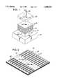
- FIG. 1is a diagrammatic perspective view illustrating a plurality of thin veneer sheets with glue on facing surfaces positioned with respect to a press cavity and a press plate and ram to form a laminated half billet panel in accordance with the present invention.
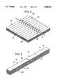
- FIG. 2is a perspective view of the half billet panel of the present invention with recesses being formed in one surface of the half billet panel.
- FIG. 3is a diagrammatic perspective view of two half billet panels oriented in relation to press components with the recesses in the half billet panels in facing relation and the facing surfaces being provided with glue for laminating the half billet panels into a completed full thickness billet panel in accordance with the present invention.
- FIG. 4is a perspective view of a completed full thickness billet panel with a gang saw arrangement schematically illustrated to show a cutting of the billet panel in accordance with the present invention into a plurality of equal sized elongated billets having generally equal square cross-sections.
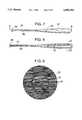
- FIG. 5is a perspective view of a square bat billet with a central core and recess formed therein in accordance with the present invention.
- FIG. 6is a transverse sectional view of a bat billet illustrating the facing recesses defining an internal core in the hitting zone of the bat to be formed from the billet in accordance with the present invention.
- FIG. 7is a plan view of a laminated wood bat of this invention formed by turning the billet of FIG. 5 in a conventional lathe operation.
- FIG. 8is a longitudinal, sectional view of the laminated wood bat taken along section line 8--8 on FIG. 7 illustrating a hollow core arrangement and reinforcing rod in the handle recess.
- FIG. 9is a transverse, sectional view, on an enlarged scale, taken along section line 9--9 on FIG. 8 illustrating further structural details of the laminates and hollow core in the hitting zone of the bat.
- FIG. 10is an enlarged top plan view of the barrel end portion of a bat in accordance with the present invention illustrating longitudinal wood grain and longitudinal edges of the laminates.
- FIG. 11is an end view of the barrel end of a bat of the present invention illustrating the laminates.
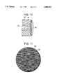
- FIG. 12is a sectional view similar to FIG. 9 but illustrating the laminates being continuous and no core being provided in the bat in accordance with the present invention.
- FIG. 13is a sectional view similar to FIG. 9 but illustrating the core filled with a less dense material such as foam plastic or other lightweight material, in accordance with the present invention.
- FIG. 14is a sectional view similar to FIG. 9 but illustrating the core filled with a material more dense than the wood laminates, such as metal to provide desired weight and balance characteristics in accordance with the present invention.
- FIGS. 1-6 of the drawingsillustrate schematically the method of forming the bat of the present invention and FIGS. 7-14 illustrate the various completed bat structures of this invention.
- the batis designated by reference numeral 20 and the external dimensional characteristics are conventional.
- the batincludes a barrel 22 which defines the hitting zone which tapers smoothly into a handle portion 24 having the usual knob 26 thereon.
- the overall length of the batmay vary within certain limits, the overall weight of the bat may also vary within certain limits with the barrel portion 22 having a diameter normally up to and including 23/4 inch, and the handle portion may have an outside diameter that may vary within limits.
- the bat 20conforms with standardized rules of various leagues, associations and the like.
- wood veneer sheets 30are used which are preferably 36 inches square but can be up to and include 48 inches square and which range in thickness from about 1/64 inch up to and including about 1/2 inches as shown in FIG. 1.
- a plurality of the veneer sheets 30are placed in the cavity 32 of press platen 34 with the surfaces of the stacked sheets 30 which face each other being provided with a layer of glue 31 applied as a thin but continuous coating not over 1/64 inch, by a conventional paint roller or the like.
- the glue 31is conventional 2 part epoxy resin.
- One preferred compositionis available from National Casein Co. of Chicago, Ill., or Bordens Packaging and Industrial Products of Bellevue, Wash.
- the number of veneer sheets 30 placed in the cavity 32will vary depending upon the thickness of the veneer sheets which preferably range between about 1/8 inch and about 1/4 inch to regulate the flexibility and rigidity to be comparable to that of a standard Ash wood bat.
- a press plate 36is engaged with the uppermost veneer sheet and a press ram 38 actuated to compress the sheets 30 and the glue with the press plate exerting approximately a 20 ton compression force.
- the veneer sheets 30all have their wood grain extending in the same direction or some of the veneer sheets or every other veneer strip may have their wood grain extending transversely.
- the veneer sheets 30are somewhat porous which enables the glue to penetrate into the interstices in the veneer sheets when the assembly of sheets 30 and glue is compressed in the press which densifies and compresses the wood fibers in the veneer sheets which increase the strength characteristics of the veneer sheets and panel.
- the assembled, compressed and densified sheets 30 and glueare then subjected to microwave or acoustic energy for curing the glue to form a stable, rigid, laminated wood veneer panel.
- the completed laminated wood veneer panelis formed by two half thickness panel 40.
- the total thickness of the compressed, densified and cured veneer half thickness panel 40is preferably about 11/2 inches. Therefore, if veneer sheets 30 are 3/8 thick, only three or four panels need be used. If the veneer sheets 30 are 1/64 inch in thickness, approximately forty-eight sheets may be used with the total thickness of the sheets 30 and glue layers being compressed and densified to form a laminated half thickness panel 40 that is approximately 11/2 inches thick as illustrated in FIG. 2.
- the laminated half thickness panel 40is used in forming the laminated wood bat embodiments illustrated in FIGS. 7-14. Preferably veneer sheets having a thickness ranging between about 1/32 inch and about 1/8 inch are used in forming the half thickness laminated panel 40.
- FIG. 2illustrates schematically by broken lines 42 how the half thickness panel 40 will be cut into half thickness billets 44 which are all preferably about 3 inches wide.
- a single half thickness panel 40will not be cut into half billets. Rather, full size elongated billets 62 are formed only after one half thickness panel 40 is assembled with another corresponding half thickness panel 40 as illustrated in FIG. 3.
- each half thickness panelis provided with one or more longitudinally extending grooves or recesses, such as at 46 and 47, by the use of a router or similar apparatus.
- the length and depth of the grooves or recesses 46 and 47are determined by the weight and balance characteristics of the finished bat.
- the transverse cross-sectional configurationis preferably generally semicylindrical with the inner ends tapering outwardly to eliminate sharp internal corners in the hitting zone and handle portion of the bat and to merge with the top surface of the panel 40.
- the outer ends of the grooves or recesses 46 and 47are generally semispherical and are spaced inwardly from the edge of half thickness panel 40.
- the facing surfacesare provided with a layer of glue and the facing surfaces have the grooves or recesses 46 and 47 oriented in aligned registry with each other inasmuch as all of the recesses and grooves are accurately positioned in the same location with respect to the surface area of each half thickness billet 44.
- a press plate 52 and ram 54are used to apply pressure to the half thickness panels 40 to cause the glue to penetrate into the facing surfaces of the half thickness panels 40.
- the glueis cured by microwave or acoustic energy to form a completed full thickness panel 60 as illustrated in FIG. 4 in which the total thickness of the full thickness panel 60 is approximately 3 inches resulting from bonding two half thickness panels 40, each approximately 11/2 inch thick, together by a layer of glue which partially penetrates into the facing surfaces of the half thickness panels 40.
- the full thickness panel 60is then cut into a plurality of full thickness square bat billets 62 by appropriately positioned gang saws 64 mounted on a shaft 66 and operated in a conventional manner to saw the full thickness panel 60 along each of the saw cut lines 68 to form longitudinally continuous full thickness bat billets 62 each of which is preferably approximately 36 inches long, but can be longer, 3 inches wide and 3 inches thick.
- the grooves or recesses 46 and 47 in each of the half billets 44are in aligned registry to form either a hollow core 72 in the hitting zone or barrel 22, or a hollow recess 73 in the handle portion 24, or both.
- a reinforcing rod 82must be positioned in the bottom recess 47 when the half thickness panels 40 are assembled. Also, if the hollow core 72 is to be filled, the filling material must be placed in the bottom recess 46 when the half thickness panels 40 are assembled.
- the reinforcing rod 82is preferably approximately 1/4 inch to 1/2 inch in diameter and is up to 18 inches long and extends longitudinally from about 1 inch inwardly from the knob end of the bat.
- the rodis preferably constructed of metal or graphite and regulates the flexibility, rigidity and strength of the handle portion of the bat.
- the full thickness bat billet 62is a stable structure with the laminates formed by the veneer sheets 30 all being generally parallel with all of the wood grain extending longitudinally of the billet or the wood grain of some of or every other one of the laminations extending transversely of the billet.
- the outer end of the core 72is spaced from the end of the square full thickness bat billet 62, as illustrated in FIG. 5.
- FIG. 6illustrates the cross-sectional structural configuration of the full thickness bat billet 62.
- the square full thickness bat billet 62is then placed in a lathe and shaped into the final external shape and configuration of the bat 20 in a well known lathe operation.
- the bat 20 as illustrated in FIGS. 7-11has external dimensional characteristics that can vary as to length and the configuration of the handle and barrel.
- the core 72has an outer end terminating inwardly from the barrel end of the bat and an inner end terminating at the inner end of the barrel portion 22 with the dimensional characteristics of the core varying to obtain the desired weight characteristics inasmuch as the glue content of the bat can constitute up to as much as approximately 25% of the bat weight.
- a conventional Ash wood bat that is 34 inches in lengthweighs approximately 32 ounces.
- the core 72is dimensioned from zero length up to 14 inches and up to 11/2 inches in diameter and, preferably, approximately 6 inches to 12 inches in length to provide a laminated bat 20 that is 34 inches long with a weight of approximately 32 ounces.
- FIG. 9illustrates the laminates defined by the wood veneer sheets 30 and illustrates the centered relationship of the core 72 with respect to the external circumference of the barrel portion 22 of the bat which maintains the bat balance with respect to its longitudinal axis. Also, the size, shape and orientation of the core 72 in the bat can be varied to provide the optimum balance point of the bat.
- FIG. 10is an enlarged view of the external surface of the bat illustrating the longitudinal edges of the wood veneer sheets 30 and also illustrating the orientation of the wood grain of the outermost wood veneer sheets when a square full thickness bat billet 62 using longitudinal wood grain in each veneer sheet is formed into the cylindrical transverse cross-section of the bat 20.
- FIGS. 10 and 11illustrate the convex contour of the tip end of the bat with FIG. 11 illustrating more specifically the orientation of the wood veneer sheets or laminates 30.
- the barrel end of the batcan be cup shaped as indicated by the dotted line 80 in FIG. 10 by terminating the core 72 about two inches from the end of the bat with the concave cup shaped end being approximately one inch deep thereby further enabling optimum orientation of the balance point of the bat and providing variation in the total weight.
- the construction of the laminated wood bat from wood veneer sheetsis cost competitive with a wood bat from a one piece billet cut from a tree in view of the increased strength characteristics resulting in a substantial increase in the useful life expectancy of the laminated bat.
- the structure of the bat and the method of forming the batenables more bats to be formed from a single tree by enabling parts of the Ash tree not formerly usable to be used in making bats.
- the use of the curable glue and its penetration into the wood veneer sheetsenables other woods, such as Poplar, to be used in making wood bats.
- the laminated wood batis substantially stronger than a conventional wood bat and substantially reduces breakage due to its increase in strength as compared to a conventional wood bat.
- the compression and densifying of the wood fibers in the porous veneer sheets 30 due to the pressure exerted by the pressalso materially increases the strength characteristics of laminated bats. Even if the laminated wood bat breaks, it does not split or break into separate components, one or both of which frequently fly towards other players or into the stands. Rather, the laminated wood bat will bend with the glue maintaining the laminates in connected relation thus introducing a substantial safety factor when using the laminated wood bat.
- a plurality of full thickness billets 62can be formed with the bat 20 then formed into final shape by use of a lathe. This enables the balance point of the bat and the total weight of the bat to be accurately determined by utilizing the core 72 which is optionally filled when assembling panels 40.
- the core 72is hollow.
- the corecan be filled with a material that is less dense than the wood veneer, such as by the use of foam plastic 74, as illustrated in FIG. 13. Suitable materials are foam urethane, foam rubber, or similar foam plastics available from many commercial sources. The foam plastic controls the weight of the bat to that of a standard Ash wood bat.
- the coremay be filled with material that is more dense than the wood, such as by the use of metal 76 or other more dense material as illustrated in FIG. 14.
- the core 72can be completely eliminated by omitting the steps of forming the recesses or grooves 46 in the half thickness panels 40 thus providing a bat that is provided with laminates 78 which are continuous transversely of the bat as illustrated in FIG. 12.
- the core 72can be any length and any size, less dense than the laminates or more dense than the laminates, or the core area may be solid with the laminates being continuous which enables the weight, balance and strength characteristics of the laminated bat to be optimized.
- the bat of this inventioncan be made without recesses 47 and hollow recess 73, although recess 73 and reinforcing rod 82 therein are preferred.
- the porosity of the wood veneer sheets 30enables the glue content to be up to approximately 25% of the total weight. It has been found that the finished bat 20 is up to approximately eight times more resistant to breakage than a conventional Ash wood bat due to compression and densification of the veneer sheets, penetration of the glue and curing the glue to permanently bond the laminates.
Landscapes
- Life Sciences & Earth Sciences (AREA)
- Engineering & Computer Science (AREA)
- Health & Medical Sciences (AREA)
- General Health & Medical Sciences (AREA)
- Physical Education & Sports Medicine (AREA)
- Wood Science & Technology (AREA)
- Manufacturing & Machinery (AREA)
- Forests & Forestry (AREA)
Abstract
Description
Claims (8)
Priority Applications (1)
| Application Number | Priority Date | Filing Date | Title |
|---|---|---|---|
| US08/745,185US5800293A (en) | 1995-08-03 | 1996-11-07 | Laminated wood bat and method of making same |
Applications Claiming Priority (2)
| Application Number | Priority Date | Filing Date | Title |
|---|---|---|---|
| US08/510,847US5620179A (en) | 1995-08-03 | 1995-08-03 | Laminated wood bat and method of making same |
| US08/745,185US5800293A (en) | 1995-08-03 | 1996-11-07 | Laminated wood bat and method of making same |
Related Parent Applications (1)
| Application Number | Title | Priority Date | Filing Date |
|---|---|---|---|
| US08/510,847DivisionUS5620179A (en) | 1995-08-03 | 1995-08-03 | Laminated wood bat and method of making same |
Publications (1)
| Publication Number | Publication Date |
|---|---|
| US5800293Atrue US5800293A (en) | 1998-09-01 |
Family
ID=24032453
Family Applications (2)
| Application Number | Title | Priority Date | Filing Date |
|---|---|---|---|
| US08/510,847Expired - LifetimeUS5620179A (en) | 1995-08-03 | 1995-08-03 | Laminated wood bat and method of making same |
| US08/745,185Expired - Fee RelatedUS5800293A (en) | 1995-08-03 | 1996-11-07 | Laminated wood bat and method of making same |
Family Applications Before (1)
| Application Number | Title | Priority Date | Filing Date |
|---|---|---|---|
| US08/510,847Expired - LifetimeUS5620179A (en) | 1995-08-03 | 1995-08-03 | Laminated wood bat and method of making same |
Country Status (1)
| Country | Link |
|---|---|
| US (2) | US5620179A (en) |
Cited By (19)
| Publication number | Priority date | Publication date | Assignee | Title |
|---|---|---|---|---|
| US6461260B1 (en) | 2000-05-15 | 2002-10-08 | Worth, Inc. | Composite wrap bat |
| US6497631B1 (en) | 1999-09-15 | 2002-12-24 | Wilson Sporting Goods Co. | Ball bat |
| US6540627B1 (en) | 2002-01-02 | 2003-04-01 | Jose E. Leal | Adjustable power bat |
| US20030150521A1 (en)* | 2000-05-31 | 2003-08-14 | Eric Liess | Method for producing decorations on an object and resulting object |
| US6761653B1 (en) | 2000-05-15 | 2004-07-13 | Worth, Llc | Composite wrap bat with alternative designs |
| US6776735B1 (en) | 1998-12-14 | 2004-08-17 | Reichhold, Inc. | Baseball bat |
| US20050124441A1 (en)* | 2003-06-23 | 2005-06-09 | Wound Wood Technologies, Llc | Spiral wound laminate wood and method for construction |
| US20060137765A1 (en)* | 2004-10-22 | 2006-06-29 | Olympus Corporation | Method of processing wood |
| US20060156665A1 (en)* | 2004-10-22 | 2006-07-20 | Olympus Corporation | Method of processing wood |
| US20090173429A1 (en)* | 2005-04-12 | 2009-07-09 | Qurz Inc. | Method for manufacturing glue laminated wood material and method for manufacturing luggage |
| US7717812B2 (en) | 2008-03-08 | 2010-05-18 | Dale R Winger | Water-based sport training |
| US20100222188A1 (en)* | 2008-03-08 | 2010-09-02 | Winger Dale R | Water-based training |
| US7841372B2 (en) | 2007-06-15 | 2010-11-30 | Gill William H | Apparatus for hardening the head area of a wooden baseball bat |
| US20110195809A1 (en)* | 2010-01-28 | 2011-08-11 | Mcdonald Matthew | Symmetrical wood composite bat |
| US20140274496A1 (en)* | 2013-03-15 | 2014-09-18 | Brett Bros. Sports International, Inc. | Multilayered Ball Bats |
| GR1009390B (en)* | 2017-05-24 | 2018-10-25 | Κωνσταντινος Θωμα Καρατσιωρης | Beach racket |
| US10940377B2 (en) | 2018-06-19 | 2021-03-09 | Easton Diamond Sports, Llc | Composite ball bats with transverse fibers |
| US11701794B1 (en)* | 2019-05-31 | 2023-07-18 | RezBats, LLC | Method of forming a sports bat and sports bat article |
| US12246230B2 (en) | 2021-08-20 | 2025-03-11 | Easton Diamond Sports, Llc | Composite ball bats with transverse interlaminar interfaces |
Families Citing this family (21)
| Publication number | Priority date | Publication date | Assignee | Title |
|---|---|---|---|---|
| CA2212211A1 (en)* | 1997-01-28 | 1998-07-28 | Sam Holman | Wooden baseball bat and method |
| US6334823B1 (en) | 1997-01-28 | 2002-01-01 | Sam J. Holman | Laminate maple baseball construction |
| USD398680S (en) | 1997-02-13 | 1998-09-22 | Kennedy Thomas J | Aluminum composite double wall bat |
| US6007440A (en)* | 1998-03-27 | 1999-12-28 | Bender; Donald A. | Laminated ball bat |
| US6234922B1 (en)* | 1998-07-06 | 2001-05-22 | Craig C. White | Fielding practice bat |
| US6238309B1 (en) | 1999-07-19 | 2001-05-29 | Joe M. Sample | Break resistant ball bat |
| US20020114034A1 (en)* | 2000-05-22 | 2002-08-22 | Winston Way | Split wave method and apparatus for transmitting data in long-haul optical fiber systems |
| US20040029660A1 (en)* | 2002-08-08 | 2004-02-12 | Chen Sam H. | Laminated sport bat with internal chamber |
| GB2391486B (en)* | 2002-08-09 | 2005-08-24 | Timothy William Keeley | Sports bat handle |
| USD526034S1 (en)* | 2003-06-26 | 2006-08-01 | Marc Christian Davis | Veneer ball bat |
| US20040266569A1 (en)* | 2003-06-26 | 2004-12-30 | Davis Marc Christian | Laminated ball bat with engineered sweet spot zone and method of making same |
| US20050020391A1 (en)* | 2003-07-17 | 2005-01-27 | Pinnacle Sports Equipment Co., Inc. | Bamboo bat and method of manufacture |
| US6916261B2 (en)* | 2003-10-03 | 2005-07-12 | Stephen M. Cullen | Composite bamboo sporting implement |
| US7771296B2 (en)* | 2008-11-05 | 2010-08-10 | Pinnacle Sports Equipment Co., Inc. | Bamboo bat having fiber-fused core and method of manufacturing the same |
| US8870688B2 (en)* | 2008-11-05 | 2014-10-28 | Pinnacle Sports Equipment Co. Inc. | Bat having fiber-fused core section and method of manufacturing the same |
| US20110094626A1 (en)* | 2009-10-27 | 2011-04-28 | Frederick Roy Bonds | Wooden sports articles and a method of manufacture |
| CN202802681U (en)* | 2012-09-10 | 2013-03-20 | 锺旻儒 | Combined type bat |
| CN203507454U (en)* | 2013-09-27 | 2014-04-02 | 锺旻儒 | Combined type bat |
| TWM480406U (en)* | 2014-02-14 | 2014-06-21 | Gao-Xing Wu | Ball bat |
| CA3220083A1 (en)* | 2022-11-14 | 2024-05-14 | Dany Chiasson | Exercise bar |
| WO2025144617A1 (en)* | 2023-12-28 | 2025-07-03 | Lightfoot Bradley W | Reinforced baseball bat and process for forming |
Citations (15)
| Publication number | Priority date | Publication date | Assignee | Title |
|---|---|---|---|---|
| US310248A (en)* | 1885-01-06 | Base-ball bat | ||
| US1450646A (en)* | 1920-05-01 | 1923-04-03 | Sadenwater Frank | Baseball bat |
| US1549803A (en)* | 1923-05-07 | 1925-08-18 | William C Rastetter | Ball bat |
| US1601915A (en)* | 1921-08-25 | 1926-10-05 | John A Hillerich | Bat |
| US1706680A (en)* | 1928-02-29 | 1929-03-26 | Smith Benjamin Boorman | Baseball bat |
| US2039221A (en)* | 1932-05-21 | 1936-04-28 | Hillerich & Bradsby Co Inc | Treatment of wood for baseball bats |
| FI22649A (en)* | 1945-12-15 | 1948-01-10 | Baseball bat | |
| US2793859A (en)* | 1955-02-08 | 1957-05-28 | Harold F Darling | Baseball bat and method of making the same |
| US4572508A (en)* | 1984-11-14 | 1986-02-25 | You Chin San | Composite laminated baseball bat |
| US4689257A (en)* | 1984-09-10 | 1987-08-25 | Baum Charles S | Veneer laminate composite structure |
| US4844460A (en)* | 1985-10-31 | 1989-07-04 | Figgie International Inc. | Method of fabricating a ball-striking implement |
| US5114144A (en)* | 1990-05-04 | 1992-05-19 | The Baum Research & Development Company, Inc. | Composite baseball bat |
| US5165686A (en)* | 1990-12-18 | 1992-11-24 | Morgan Edward H | Wooden baseball bat |
| US5476706A (en)* | 1992-11-16 | 1995-12-19 | Shimizu; Okiyoshi | Sporting implement having a head portion with a hitting surface for contacting a ball |
| US5490669A (en)* | 1992-10-13 | 1996-02-13 | Smart; Merlin L. | Laminated ball bat |
Family Cites Families (2)
| Publication number | Priority date | Publication date | Assignee | Title |
|---|---|---|---|---|
| US1121189A (en)* | 1914-06-13 | 1914-12-15 | Spalding & Bros Ag | Base-ball bat. |
| US1603904A (en)* | 1926-04-13 | 1926-10-19 | Cohn Edward | Reenforced bat |
- 1995
- 1995-08-03USUS08/510,847patent/US5620179A/ennot_activeExpired - Lifetime
- 1996
- 1996-11-07USUS08/745,185patent/US5800293A/ennot_activeExpired - Fee Related
Patent Citations (15)
| Publication number | Priority date | Publication date | Assignee | Title |
|---|---|---|---|---|
| US310248A (en)* | 1885-01-06 | Base-ball bat | ||
| US1450646A (en)* | 1920-05-01 | 1923-04-03 | Sadenwater Frank | Baseball bat |
| US1601915A (en)* | 1921-08-25 | 1926-10-05 | John A Hillerich | Bat |
| US1549803A (en)* | 1923-05-07 | 1925-08-18 | William C Rastetter | Ball bat |
| US1706680A (en)* | 1928-02-29 | 1929-03-26 | Smith Benjamin Boorman | Baseball bat |
| US2039221A (en)* | 1932-05-21 | 1936-04-28 | Hillerich & Bradsby Co Inc | Treatment of wood for baseball bats |
| FI22649A (en)* | 1945-12-15 | 1948-01-10 | Baseball bat | |
| US2793859A (en)* | 1955-02-08 | 1957-05-28 | Harold F Darling | Baseball bat and method of making the same |
| US4689257A (en)* | 1984-09-10 | 1987-08-25 | Baum Charles S | Veneer laminate composite structure |
| US4572508A (en)* | 1984-11-14 | 1986-02-25 | You Chin San | Composite laminated baseball bat |
| US4844460A (en)* | 1985-10-31 | 1989-07-04 | Figgie International Inc. | Method of fabricating a ball-striking implement |
| US5114144A (en)* | 1990-05-04 | 1992-05-19 | The Baum Research & Development Company, Inc. | Composite baseball bat |
| US5165686A (en)* | 1990-12-18 | 1992-11-24 | Morgan Edward H | Wooden baseball bat |
| US5490669A (en)* | 1992-10-13 | 1996-02-13 | Smart; Merlin L. | Laminated ball bat |
| US5476706A (en)* | 1992-11-16 | 1995-12-19 | Shimizu; Okiyoshi | Sporting implement having a head portion with a hitting surface for contacting a ball |
Cited By (25)
| Publication number | Priority date | Publication date | Assignee | Title |
|---|---|---|---|---|
| US6776735B1 (en) | 1998-12-14 | 2004-08-17 | Reichhold, Inc. | Baseball bat |
| US6497631B1 (en) | 1999-09-15 | 2002-12-24 | Wilson Sporting Goods Co. | Ball bat |
| US6761653B1 (en) | 2000-05-15 | 2004-07-13 | Worth, Llc | Composite wrap bat with alternative designs |
| US6869372B1 (en) | 2000-05-15 | 2005-03-22 | Worth, Llc | Composite wrap bat |
| US6461260B1 (en) | 2000-05-15 | 2002-10-08 | Worth, Inc. | Composite wrap bat |
| US7114419B2 (en)* | 2000-05-31 | 2006-10-03 | Eric Liess | Method for producing decorations on an object and resulting object |
| US20030150521A1 (en)* | 2000-05-31 | 2003-08-14 | Eric Liess | Method for producing decorations on an object and resulting object |
| US6540627B1 (en) | 2002-01-02 | 2003-04-01 | Jose E. Leal | Adjustable power bat |
| US20050124441A1 (en)* | 2003-06-23 | 2005-06-09 | Wound Wood Technologies, Llc | Spiral wound laminate wood and method for construction |
| US7322389B2 (en)* | 2004-10-22 | 2008-01-29 | Olympus Corporation | Method of processing wood |
| US20060156665A1 (en)* | 2004-10-22 | 2006-07-20 | Olympus Corporation | Method of processing wood |
| US7296604B2 (en)* | 2004-10-22 | 2007-11-20 | Olympus Corporation | Method of processing wood |
| US20060137765A1 (en)* | 2004-10-22 | 2006-06-29 | Olympus Corporation | Method of processing wood |
| US20090173429A1 (en)* | 2005-04-12 | 2009-07-09 | Qurz Inc. | Method for manufacturing glue laminated wood material and method for manufacturing luggage |
| US7841372B2 (en) | 2007-06-15 | 2010-11-30 | Gill William H | Apparatus for hardening the head area of a wooden baseball bat |
| US20100222188A1 (en)* | 2008-03-08 | 2010-09-02 | Winger Dale R | Water-based training |
| US7717812B2 (en) | 2008-03-08 | 2010-05-18 | Dale R Winger | Water-based sport training |
| US8096902B2 (en) | 2008-03-08 | 2012-01-17 | Winger Dale R | Water-based training |
| US20110195809A1 (en)* | 2010-01-28 | 2011-08-11 | Mcdonald Matthew | Symmetrical wood composite bat |
| US8795107B2 (en) | 2010-01-28 | 2014-08-05 | Matthew McDonald | Symmetrical wood composite bat |
| US20140274496A1 (en)* | 2013-03-15 | 2014-09-18 | Brett Bros. Sports International, Inc. | Multilayered Ball Bats |
| GR1009390B (en)* | 2017-05-24 | 2018-10-25 | Κωνσταντινος Θωμα Καρατσιωρης | Beach racket |
| US10940377B2 (en) | 2018-06-19 | 2021-03-09 | Easton Diamond Sports, Llc | Composite ball bats with transverse fibers |
| US11701794B1 (en)* | 2019-05-31 | 2023-07-18 | RezBats, LLC | Method of forming a sports bat and sports bat article |
| US12246230B2 (en) | 2021-08-20 | 2025-03-11 | Easton Diamond Sports, Llc | Composite ball bats with transverse interlaminar interfaces |
Also Published As
| Publication number | Publication date |
|---|---|
| US5620179A (en) | 1997-04-15 |
Similar Documents
| Publication | Publication Date | Title |
|---|---|---|
| US5800293A (en) | Laminated wood bat and method of making same | |
| EP1861181B1 (en) | Cue stick and method of making same | |
| US4572508A (en) | Composite laminated baseball bat | |
| US5217221A (en) | Hockey stick formed of composite materials | |
| US4200479A (en) | Method of making a hockey stick | |
| US4159114A (en) | Ice hockey stick | |
| US4968032A (en) | Hockey stick shaft | |
| TWI685425B (en) | Skateboard decks | |
| US20090108554A1 (en) | Skateboard deck | |
| US5810676A (en) | Lightweight shaft | |
| US4070019A (en) | Laminated game rackets and method of constructing same | |
| US2894503A (en) | Archery bow | |
| US20050124441A1 (en) | Spiral wound laminate wood and method for construction | |
| US20040163571A1 (en) | Fire door core assembly | |
| US4555115A (en) | Golf club head construction | |
| FI69566C (en) | RACKETRAM BYGGD AV LAMINAT | |
| CA1310674C (en) | Reinforced hockey stick | |
| US6942587B2 (en) | Hollow wooden hockey stick | |
| EP3917769B1 (en) | Sliding board with corrugated mediums | |
| CA1325096C (en) | Laminated veneer round pole | |
| EP0077134A1 (en) | Method for making fiber sheet reinforced wood racket | |
| CN205073617U (en) | A racket for ball game | |
| US4313614A (en) | Ski and its manufacture | |
| JPH0225412Y2 (en) | ||
| US3099449A (en) | Wooden bowling pins of spherical belly type and prefabricated segments therefor |
Legal Events
| Date | Code | Title | Description |
|---|---|---|---|
| AS | Assignment | Owner name:HILLERICH & BRADSBY CO., KENTUCKY Free format text:CONSUOTING AGREEMENT;ASSIGNOR:MACKAY, J.W., JR.;REEL/FRAME:008635/0005 Effective date:19920701 | |
| AS | Assignment | Owner name:HILLERICH & BRADSBY CO., KENTUCKY Free format text:ASSIGNMENT OF ASSIGNORS INTEREST;ASSIGNOR:MACKAY, JACK W., JR.;REEL/FRAME:008703/0305 Effective date:19970829 | |
| FPAY | Fee payment | Year of fee payment:4 | |
| FPAY | Fee payment | Year of fee payment:8 | |
| AS | Assignment | Owner name:PNC BANK, NATIONAL ASSOCIATION, OHIO Free format text:SECURITY AGREEMENT;ASSIGNOR:HILLERICH & BRADSBY & CO.;REEL/FRAME:022443/0676 Effective date:20081230 Owner name:PNC BANK, NATIONAL ASSOCIATION,OHIO Free format text:SECURITY AGREEMENT;ASSIGNOR:HILLERICH & BRADSBY & CO.;REEL/FRAME:022443/0676 Effective date:20081230 | |
| REMI | Maintenance fee reminder mailed | ||
| LAPS | Lapse for failure to pay maintenance fees | ||
| STCH | Information on status: patent discontinuation | Free format text:PATENT EXPIRED DUE TO NONPAYMENT OF MAINTENANCE FEES UNDER 37 CFR 1.362 | |
| FP | Lapsed due to failure to pay maintenance fee | Effective date:20100901 | |
| AS | Assignment | Owner name:HILLERICH & BRADSBY CO., KENTUCKY Free format text:REASSINMENT AND RELEASE OF SECURITY INTEREST-PATENTS;ASSIGNOR:PNC BANK, NATIONAL ASSOCIATION;REEL/FRAME:031709/0923 Effective date:20130809 | |
| AS | Assignment | Owner name:WELLS FARGO BANK, NATIONAL ASSOCIATION, NEW YORK Free format text:SECURITY AGREEMENT;ASSIGNOR:HILLERICH & BRADSBY CO.;REEL/FRAME:032817/0181 Effective date:20130809 | |
| AS | Assignment | Owner name:CRYSTAL FINANCIAL SBIC LP, MASSACHUSETTS Free format text:SECURITY INTEREST;ASSIGNOR:HILLERICH & BRADSBY CO.;REEL/FRAME:033258/0602 Effective date:20140627 | |
| AS | Assignment | Owner name:HILLERICH & BRADSBY, CO., KENTUCKY Free format text:RELEASE BY SECURED PARTY;ASSIGNOR:WELLS FARGO BANK, NATIONAL ASSOCIATION;REEL/FRAME:035476/0003 Effective date:20150421 | |
| AS | Assignment | Owner name:HILLERICH & BRADSBY, CO., KENTUCKY Free format text:RELEASE BY SECURED PARTY;ASSIGNOR:CRYSTAL FINANCIAL SBIC LP;REEL/FRAME:035485/0966 Effective date:20150421 |