US5799204A - System utilizing BIOS-compatible high performance video controller being default controller at boot-up and capable of switching to another graphics controller after boot-up - Google Patents
System utilizing BIOS-compatible high performance video controller being default controller at boot-up and capable of switching to another graphics controller after boot-upDownload PDFInfo
- Publication number
- US5799204A US5799204AUS08/432,106US43210695AUS5799204AUS 5799204 AUS5799204 AUS 5799204AUS 43210695 AUS43210695 AUS 43210695AUS 5799204 AUS5799204 AUS 5799204A
- Authority
- US
- United States
- Prior art keywords
- video
- controller
- slot
- standard
- subsystem
- Prior art date
- Legal status (The legal status is an assumption and is not a legal conclusion. Google has not performed a legal analysis and makes no representation as to the accuracy of the status listed.)
- Expired - Lifetime
Links
Images


Classifications
- G—PHYSICS
- G09—EDUCATION; CRYPTOGRAPHY; DISPLAY; ADVERTISING; SEALS
- G09G—ARRANGEMENTS OR CIRCUITS FOR CONTROL OF INDICATING DEVICES USING STATIC MEANS TO PRESENT VARIABLE INFORMATION
- G09G5/00—Control arrangements or circuits for visual indicators common to cathode-ray tube indicators and other visual indicators
- G09G5/36—Control arrangements or circuits for visual indicators common to cathode-ray tube indicators and other visual indicators characterised by the display of a graphic pattern, e.g. using an all-points-addressable [APA] memory
- G09G5/363—Graphics controllers
- G—PHYSICS
- G06—COMPUTING OR CALCULATING; COUNTING
- G06F—ELECTRIC DIGITAL DATA PROCESSING
- G06F3/00—Input arrangements for transferring data to be processed into a form capable of being handled by the computer; Output arrangements for transferring data from processing unit to output unit, e.g. interface arrangements
- G06F3/14—Digital output to display device ; Cooperation and interconnection of the display device with other functional units
- G—PHYSICS
- G09—EDUCATION; CRYPTOGRAPHY; DISPLAY; ADVERTISING; SEALS
- G09G—ARRANGEMENTS OR CIRCUITS FOR CONTROL OF INDICATING DEVICES USING STATIC MEANS TO PRESENT VARIABLE INFORMATION
- G09G2360/00—Aspects of the architecture of display systems
- G09G2360/06—Use of more than one graphics processor to process data before displaying to one or more screens
Definitions
- the present inventionrelates to apparatus and methods for video controllers, and more particularly to apparatus and methods for high-performance video controllers in microprocessor-based computers.
- Busesprovide the communication path between the computer's central processing unit (CPU) and other components of the computer, such as memory and interfaces to peripheral devices, e.g. monitors, printers, disk drives, modems, etc.
- Buses, including the PCI bustypically have a plurality of slots for receiving a slot connector associated with a peripheral device.
- a monitortypically is connected to the bus by a video card with a slot connector.
- BIOSbasic input-output system
- video controllertypically, a video graphics adapter--VGA
- BIOSbasic input-output system
- the standard video controlleris usually found on the video card that links the monitor to the PCI bus.
- the inventionis a high-performance video controller for a microprocessor-based computer having a bus, which has a plurality of slots for receiving slot connectors for peripheral-type devices (such as video cards, disk drive controllers and modems), wherein (i) the bus is of the type imposing a single-device-per-slot limitation and (ii) the computer has a BIOS requiring on boot-up of the computer the presence of a standard video controller (e.g. VGA).
- a standard video controllere.g. VGA
- the inventionincludes (a) a connector arrangement having at least one slot connector, and (b) a standard-video-controller subsystem coupled to the connector arrangement and having a video output, and (c) a second-video-controller subsystem that is also coupled to the connector arrangement and that also has a video output.
- the standard-video-controller subsystemincludes the electronic components--or component--one would normally find in a standard video controller.
- the second-video-controller subsystempreferably includes the electronic components for a video controller that is more advanced than the standard video controller (and which, presumably, is not recognized by the standard BIOS).
- the second-video-controller subsystemincludes all the electronic components necessary for an advanced graphics controller.
- the connector arrangementhas a plurality of slot connectors so that the standard-video-controller subsystem is connected to a separate slot from the second-video-controller subsystem, which also has its own slot.
- only a single slot connectoris used, and the two subsystems share the same slot through a switching arrangement.
- the slot connectorsare preferably mechanically rigidly linked to one another, spaced apart the same amount as the bus's slots, so that the two connectors can be plugged into parallel slots together. It is also preferred to use a plurality of circuit boards that are also mechanically rigidly linked to one another, such that each slot connector is associated with one of the circuit boards. Such a connection between the circuit boards allows a two-circuit-board configuration to be handled and installed efficiently and conveniently.
- the inventionincludes a switch configured to provide, at the system video output, the video output of the standard-video-controller subsystem during boot-up and otherwise the video output of the second-video-controller subsystem.
- the switch arrangementis disposed between (i) the video outputs of each of the standard-video-controller subsystem and the second-video-controller subsystem and (ii) the system video output.
- a bridging switch arrangementmay be also be disposed between (i) each of the standard-video-controller subsystem and the second-video-controller subsystem and (ii) the connector arrangement, preferably along with a switch arrangement disposed between (i) the video outputs of each of the standard-video-controller subsystem and the second-video controller subsystem and (ii) the system video output.
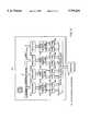
- FIG. 1is a block diagram of showing modules of a video graphics processor-controller may be used in the present invention.
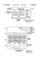
- FIG. 2is a block diagram of a graphics processor system that may be used in a preferred embodiment of the present invention.
- FIG. 3is a block diagram of a frame buffer system that may be used with the graphics processor system shown in FIG. 2.
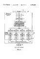
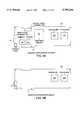
- FIG. 4is a block diagram showing a preferred embodiment of the invention.
- FIG. 5is a block diagram showing an alternative embodiment of the invention.
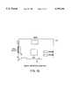
- FIGS. 6A-6Dshow a variety of switch arrangements that may be used in the embodiments shown in FIGS. 4 and 5.
- FIGS. 7A-7Eshow an arrangement of circuit boards for implementing an embodiment of the invention using the graphics processor and frame buffer systems shown in FIGS. 2 and 3.
- FIG. 8is a block diagram of an alternative graphics processor system (including the frame buffer system) that may be used in the present invention.
- FIGS. 9A-9Dshow an arrangement of circuit boards for implementing an embodiment of the invention using the graphics processor system shown in FIG. 8.
- a preferred embodiment of the present inventionhas been implemented using, as the second-video-controller subsystem, a graphics controller-processor having the general structure shown in FIG. 1.
- This embodimentis suitable for use with computers, such as those utilizing the Intel family of 80 ⁇ 86 processors (including the Pentium), running an operating system such as Microsoft Windows NT, designed to communicate over a PCI Local Bus, pursuant to the PCI Local Bus Specification, revision 2.0 (Apr. 30, 1993), which has been incorporated hereinabove by reference.
- the embodimentmay also be configured, for example, to operate in an X-windows Unix environment, and on other buses, such as VL (VESA Local Bus).
- VLVESA Local Bus
- the architecture of this graphics controller-processorcan be broken down into six basic subsystems. Of these two are optional.
- the basic systemhas a graphics engine 12 that accepts requests via a FIFO buffer 11. These requests are broken down by the graphics engine 12 into pixel requests, which are written over a wide high-speed (secondary) bus 17 to a set of resolvers 13, which in turn control reading and writing of the frame buffer 14.
- the back end subsystem 18reads the frame buffer and displays it on the screen of a suitable monitor.
- the texture processors 15 and roam processor 16are optional subsystems.
- the roam processor subsystemincludes its own resolvers 161 and roam frame buffer 162.
- FIGS. 2 and 3are more detailed block diagrams of an advanced graphics processor system and a frame buffer system in accordance with the embodiment of FIG. 1 and are referred to in the discussion below.
- the components of this systemare placed on circuit boards--more than one circuit board being necessary because of the large number of processing and memory components required.
- the rendering subsystemincludes the PCI buffer 202, which is an ASIC (application specific integrated circuit), the DMA ASIC 211, graphics FIFO 21, and graphics engine ASIC 22.
- Renderingis the process of drawing triangles, lines, and line strings.
- the rendering subsystemalso performs region fill operations, bit expands and blit operations.
- Software on the host processorperforms the necessary 3D transform and lighting calculations. These calculations result in vertex data which consists of coordinate (X,Y,Z) and color information (R,G,B,A).
- the host computertypically sends the vertex data to a buffer in main memory.
- the vertex dataenters the rendering subsystem through the PCI bus interface in the PCI buffer ASIC 202.
- the PCI buffer 202 ASICprovides an internal FIFO to allow PCI bus burst transfers. It also provides an interface to the expansion cable.
- the DMA ASIC 211is a multichannel, Direct Memory Access (DMA) engine capable of burst transfer for lengths of up to 4MB.
- the system softwareuses the DMA ASIC to transfer vertex data from main memory of the host computer to the graphics FIFO 21.
- the graphics engine ASIC 22is the main graphics processor and the core of the rendering subsystem. It takes vertex data from the graphics FIFO 21 and produces rendered spans of pixel data. The graphics engine ASIC 22 sends the data to the frame buffer subsystem over a high speed pixel path called the Image/Z (IZ) bus 27.
- IZImage/Z
- the graphics engineuses for major logic blocks to perform the pixel rendering. They are: (1) request handler, (2) slope calculation, (3) span generation, and (4) pixel interpolation.
- the request handlermonitors the output of the graphics FIFO 21 for data. When data arrives, the request handler analyzes it and writes it to an appropriate processing block. The request handler routes vertex data for triangles and lines to the slope calculation block. Drawing requests (other than vertex data for triangles and lines) such as blits, fills, and bit expands, bypass the slope calculation and span generation blocks. The request handler routes this data directly to the pixel interpolation block.
- the slope calculation blockperforms the slope calculation part of the rendering process for triangles and lines. Floating-point math ensures the accuracy of triangle edges.
- the slope calculation blockcalculates color derivatives, depth derivatives, and edge slopes. It also adjusts the vertex data to a pixel center for the topmost vertex.
- the slope calculation blockconverts all data to a fixed-point format and routes it to the span generation block.
- the span generation blockperforms the span calculation part of the rendering process for triangles and lines.
- the span generation blockdetermines the leftmost x and y coordinates for each scan line in a triangle. It also calculates the initial color and depth value for each scanline, and routes the data to the pixel interpolation block.
- the pixel interpolation blockis common for all graphics drawing requests. For triangle meshes, the pixel interpolation block expands the data from the span generation block to pixel data by successively adding the x-derivative value to the initial color and depth values (z) for each span.
- the pixel interpolation blockalso maps the (x,y) address to a linear address before sending the address and pixel data to either the frame buffer or texture subsystem 250 over the IZ bus.
- the IZ bus 27is a 64 bit, 256 MB per second bus with a pixel span protocol to facilitate high data throughput. This protocol allows burst transfers of pixel data to occur between the rendering subsystem and the frame buffer subsystem. The maximum burst size is 4096 pixels.
- the graphics engine 22is thus an ASIC which receives requests from a host processor via the PCI system bus 201. Requests are written to graphics FIFO buffer 21 and are read, decoded and executed by the graphics engine 22. Requests include graphic primitives (points, lines and triangles), rectangular fill, get/put pixel data, blits, and control requests.
- the graphics enginealso supports a second FIFO interface which can connect to a boardset enabling fast JPEG decompression and display to the frame buffer.
- the four resolver ASICs 331-334 on the graphics processor boardcontrol the flow of data to and from the frame buffer memory. These resolvers provide a 256-bit frame buffer interface. This wide interface allows the embodiment to achieve a very high drawing bandwidth.
- the resolversthus coordinate the movement of data from the frame buffer memory to the video selector and mapper (VSM) ASIC chips 381-388 and DAC 39 (digital to analog converter) in the display subsystem.
- VSMvideo selector and mapper
- DAC 39digital to analog converter
- the graphics engine ASIC 22sends interpolated pixel data over the IZ bus 27 to the resolver ASIC's IZ input FIFO.
- the pixel dataconsists of color (Red, Green, Blue, and Alpha-RGBA) and depth (Z) data.
- the resolver IZ input FIFOis 128 words deep, so that the resolver can accommodate bursts of pixel data without slowing overall system performance.
- the resolverexamines pixel data from the input FIFO and determines if it should write the pixel data to the VRAM (video RAM) on the frame buffer board.
- the resolverperforms Z, mask and alpha tests to determine if data should be written.
- the resolvermay perform an Arithmetic and Logic Unit (ALU) operation on a combination of the source data (data from the graphics engine) and the destination data (data in VRAM).
- ALUArithmetic and Logic Unit
- the operationsinclude logical operations, Porter and Duff style alpha blend operations, and OpenGL style alpha blend operations.
- the resolverperforms several different types of VRAM write cycles including reads, writes, or read-modify-writes. It maximizes memory bandwidth by choosing an appropriate type. The resolver performs block write cycles to maximize performance for window clear and fill requests.
- the resolvers 331-334are thus a set of identical ASICs that accept span requests over the IZ bus 27 and read from or write to the frame buffer formed by VRAM memory chips 341-314. They also perform the tasks of masking, alpha test, Z buffering, and frame buffer merge (read/modify/write) operations (such as X windows ALU operations and alpha blend operations).
- the basic systemcontains one frame buffer--virtual screens are not supported--but in a typical embodiment 34 MB of memory is provided by 136 VRAMs, each VRAM having 2 megabits of memory. Each pixel in the frame buffer memory in this embodiment then has 126 bits or planes.
- This frame bufferallows window-based double buffering on up to 15 different windows independently in each of the three sets of planes. They are also used to specify RGB to VLT routing for the image planes, and are used to allow roam buffer display in a window.
- Most writes to the frame bufferare to a single "visual"-- i.e. a single set of planes. For example, visual 2 is the image (RGB) set of planes, and visual 1 is the overlay set of planes. Certain "implied" data may be written at the same time a write occurs to some visuals.
- the implied datacomes out of a static register in the graphics engine (via the span header) and consists of the control data which is listed with the visible planes above--for example a write to the image planes can also write the WID2 bits and the image VLT context bits. Implied writes may be independently enabled or disabled via write enables.
- the back endhas a set of VSMs 381-388 (Video Selector and Mapper) which drive RAM DACs 39 (Digital to Analog Converters), and the video timing logic.
- VSM ASICreceives pixel data from the frame buffer. It selects which buffer (front or back), and which data (image or overlay), to display.
- the VSMuses the video selection planes to choose a VLT mapping if it decides to display image planes.
- the VSMsends the mapping result to the DAC on the processor board.
- the VSMsthus read the appropriate planes of the frame buffer, perform lookup through one of the 8 VLTs, and send RGB to the RAMDACs.
- the DACconverts pixel data from the VSM to an analog voltage and sends it to a monitor 391 for display.
- the integrated DACcontains a Video Lookup Table (VLT) consisting of 256 locations ⁇ 3 colors (RGB) ⁇ 10 bits per color used for gamma correction.
- VLTVideo Lookup Table
- the DACalso provides a user definable 64 ⁇ 64 pixel hardware cursor.
- the WID bits associated with those planesare used to index into one of three small lookup tables.
- a bit in this LUTselects which buffer is to be displayed for that plane set.
- the LUT associated with the image planesalso is used to specify routing between the RGB planes and the VLTs.
- the overlay VLT context bitis used to select between VLT context 0 and 1.
- the image VLT context bitscan select any of the 8 VLT contexts available. All VLT contexts are capable of being specified as either pseudo color or true color when driven by the image visual.
- Bits in the WID tablesare also provided to select the roam buffer, and disable display of the overlay and highlight planes.
- the roam subsystemis shown in FIG. 1. (For purposes of simplicity, it is not shown in FIG. 3, but is generally analogous in structure to the frame buffer structure shown in FIG. 3.)
- This subsystemis effectively an additional frame buffer larger than the actual screen size.
- This buffercan be roamed in a toroidal fashion within a window in the static frame buffer.
- the frame bufferhas a set of resolvers 161 that are configured as "roamers” connected to the IZ bus 17, the frame buffer 14 as above, and a pixel shifter followed by a set of VSMs (like 381-388) which feed into the digital RGB stream to the RAMDACs 39. Since the VLTs are in the VSMs, the roam buffer has its own set of 8 VLT contexts.
- the roam bufferdisplays through a window defined by the WID bits in the static frame buffer.
- Each of the WIDsindex into their lookup table in the static frame buffer VSMs, and if all three enable the roam buffer, the roam buffer will display. If any do not select roam, roam will not display. This allows static frame buffer pixels to overlay the roam buffer.
- the texturing subsystem 250is an optional subsystem which interfaces solely through the IZ bus 27.
- the texturing subsystem 250logically lies between the rendering subsystem and the frame buffer subsystem.
- the texturing subsystem 250comprises four texture processor ASICs 251-254 and 32 MB of texture memory 251a, 252a, 253a and 254a. Each texture processor ASIC performs texturing operations for a single band (red, green, blue or alpha) or texture memory.
- the texture processors 251-254receive two types of setup parameters from the graphics engine 22: one type for triangles and one type for pixel spans within a triangle.
- the triangle setup parametersconsist of texturing control information and texture coordinate derivatives
- the pixel span setup parametersconsist of initial texture coordinates.
- the texture memoryis capable of storing several sets of mip-mapped textures for subsequent texture mapping.
- mip-mappingmultiple-sized versions of a texture are stored. Each version is filtered to account for distance from the viewer.
- the texture processorchooses eight texels nearest the actual texel value from the nearest two mip maps.
- the texture processorinterpolates these eight texels to produce the actual texel value through the use of trilinear interpolation.
- the actual texel valuereplaces or blends with the Gouraud shaded pixel value generated by the graphics engine 22.
- the texture processorsroute the textured pixels to the resolvers 331-334 and the resolvers 331-334 write the textured pixels into the frame buffer 341-344.
- the graphics engine 22When the graphics engine 22 receives textured requests (that is, requests which contain texture coordinates), it sends special span requests to the texturing subsystem 250 over the IZ bus 27.
- the texturing subsystem 250intercepts these spans, textures the pixels within it, and then resends the span to the resolvers 331-334.
- Texture memory 251a, 252a, 253a, and 254alooks like frame buffer memory 341-344 to the graphics engine, and is loaded/read back by normal get/put and fill operations.
- FIGS. 4 and 5show two ways that the above-described advanced graphics processing system may be used in the present invention as a second-video-controller subsystem.
- a preferred arrangement shown in FIG. 4uses two slots on the PCI bus.
- a VGA subsystem 41is connected to a PCI bus slot 43.
- An advanced graphics subsystem 42is attached to a separate PCI bus slot 44.
- Both of these subsystemsare connected to the monitor 391 through a switch 46 that permits either the VGA subsystem 41 or the advanced graphics subsystem 42 to transmit video signals to the monitor 391.
- the switching functionmay be accomplished in a number of ways, including without limitation by an analog multiplexer such as that shown in FIG. 6A, by several FET switches such as the arrangement shown in FIG. 6B, by a wired-OR arrangement as shown in FIG. 6C where the selection is performed by current-mode DACs, or by a relay such as that shown in FIG. 6D. Digital means may also be used to affect the switching.
- the advanced graphics subsystem 42preferably provides a video select signal to the switch 46 to cause the switch to select either of the two subsystems.
- This video select signalwould normally be triggered after the BIOS boot-up, when the software for the advanced graphics subsystem is loaded and executed and then indicates to the advanced graphics subsystem to take over the video processing function from the VGA subsystem (or other standard-video-controller subsystem).
- the VGA subsystemis typically only used during the boot process and in full-screen DOS mode. The user can select to display either VGA mode or advanced-graphics mode.
- VGA subsystem 41 and the advanced graphics subsystem 42share the same PCI bus slot 41.
- a bridge 51 that switches between the VGA subsystem 41 and the advanced graphics subsystem 42connects these two subsystems to the PCI bus slot 41.
- FIGS. 7A-7Eshow how the components of a video controller according to the present invention and including a VGA subsystem 41 and an advanced graphics subsystem 42 based on the graphics processor and frame buffer systems shown in FIGS. 2 and 3 are arranged on circuit boards.
- most of the video controller's componentsare located outside of the host computer's housing.
- the host adapter board 270Inside the host computer's housing is the host adapter board 270, which includes a slot connector 71 for attaching to the host computer's PCI bus, a PCI buffer chip (PCIBUF) 202 and other buffer components 74, and a connector 73 for a cable, which is represented in FIG. 2 as connecting the PCIBUF component 202 on the host adapter board 270 to the expansion adapter 203.
- the cableconnects the components of the video controller inside the host computer's housing with video controller components located in a separate housing.
- FIG. 7Bshows the expansion adapter board 203, which provides the interface between the host adapter board 270 and the components in the separate housing, and which includes a cable connector 75 for connecting to the other end of the cable attached to the connector 73 of the host adapter board 270.
- the expansion adapter board 203receives and buffers the image data from the host adapter board 270, and includes memory chips 76 for use as the data buffer.
- FIG. 7Cshows the graphics processor board 280, which is also represented in the block diagram of FIG. 2.
- the graphics processor board 280includes a DMA chip 211, a graphics-engine chip 22, a connector 271 for the IZ bus (item 27 in FIGS.
- FIG. 7Dshows the frame buffer board 310, which is represented in the block diagram of FIG. 3.
- the frame buffer board 310includes a connector 272 for the IZ bus, resolver chips 33, video RAM chips 34, VSM chips 38 and a RAMDAC chip 39.
- the frame buffer board 310also includes a connector 79 for connecting to the VGA board 411, which is mounted in the host computer's housing, and a connector 91 for connecting the monitor.
- the VGA board 411which is depicted in FIG. 7E, includes a slot connector 72 for connecting to the PCI bus, and a VGA port 78, which may be connected by means of a cable to the VGA connector 79 on the frame buffer board 310.
- FIG. 8An alternative advanced graphics processing system is depicted as a block diagram in FIG. 8. It will be appreciated that this system has components that are similar in nature to some of the components shown in the system shown in FIGS. 2 and 3.
- the FIG. 8 systemis connected to the PCI bus 201, and includes a PCIDMA 211, a graphics FIFO buffer 21, a graphics engine 22, and IZ bus 27, resolvers 33, video RAM 34, VSMs 38 and a D/A converter 39, which is connected to a monitor 391. Further details of this graphics processing system and how it may be implemented in the present invention may be found in the GLZ Hardware Technical Reference published Aug. 1994 by Intergraph Corporation, Huntsville, Ala. 35894-0001.
- FIGS. 9A-9Dshows one preferred arrangement of components.
- FIGS. 9A and 9Bdepict the front and back sides of the graphics processor board 281, which is represented in the block diagram of FIG. 8 as including all the advanced graphics components except for the video RAM 34 and the VSMs 38.
- the graphics processor board 281includes a slot connector 71 for connecting to the PCI bus, a PCIDMA chip 211, a graphics-engine chip 22, and resolvers 332.
- the graphics processor board 281is electrically connected--such as by means of a ribbon cable--to the frame buffer board 282, the front and back of which is depicted in FIGS. 9C and 9D, and which is also depicted in the block diagram of FIG. 8.
- the frame buffer board 282includes video RAM chips 34 and VSM chips 381-384, as shown in FIGS. 9C and 9D.
- the signals from the VSM chips 381-384are sent back to the graphics processor board 281, where they are converted into analog signals by the RAMDAC chip 39.
- the analog signalsthen pass to the video port 91, which is connected to the monitor.
- a VGA chip 412(such as the Cirrus 5434 chip) is mounted on the frame buffer board 282.
- the VGA chip 412is connected to the PCI bus by means of the slot connector 72 on the frame buffer board 282.
- the VGA chipis also connected electrically through a switch (item 46 in FIG. 4) to the video port 91 on the graphics processor board 281.
- the frame buffer boardholds components from both the advanced graphics subsystem (the VSMs and the video RAM) and the standard-video-controller subsystem (the VGA chip), and further provides separate access for the standard-video-controller subsystem to the PCI bus--through the slot connector 72.
- the advanced graphics subsystem's access to the PCI busis through the slot connector 71 on the graphics processor board 281, but since this board (the dimensions of which are dictated by the dimensions of the personal computer's housing) cannot fit all of the components for the advanced graphics subsystem, some of the advanced graphics subsystem's components are placed on the board--the frame buffer board 282--containing the component or components of the standard-video-controller subsystem (the VGA chip 412).
- the graphics processor board 281 and the frame buffer board 282can be separately installed in the host computer's housing and then electrically connected by means of a ribbon cable or the like
- the preferred embodiment of the inventionhas the two boards rigidly and mechanically fastened to each other, by bolts or the like, with spacers to keep the two boards--and importantly the two slot connectors 71 and 72--spaced apart the correct amount, i.e., the amount that the slots in the host computers bus are spaced apart.
- Such an arrangement, where the boards are mechanically as well as electrically linkedeases the installation of the video controller system.
Landscapes
- Engineering & Computer Science (AREA)
- Computer Graphics (AREA)
- Physics & Mathematics (AREA)
- Computer Hardware Design (AREA)
- General Physics & Mathematics (AREA)
- Theoretical Computer Science (AREA)
- Controls And Circuits For Display Device (AREA)
Abstract
Description
Claims (18)
Priority Applications (1)
| Application Number | Priority Date | Filing Date | Title |
|---|---|---|---|
| US08/432,106US5799204A (en) | 1995-05-01 | 1995-05-01 | System utilizing BIOS-compatible high performance video controller being default controller at boot-up and capable of switching to another graphics controller after boot-up |
Applications Claiming Priority (1)
| Application Number | Priority Date | Filing Date | Title |
|---|---|---|---|
| US08/432,106US5799204A (en) | 1995-05-01 | 1995-05-01 | System utilizing BIOS-compatible high performance video controller being default controller at boot-up and capable of switching to another graphics controller after boot-up |
Publications (1)
| Publication Number | Publication Date |
|---|---|
| US5799204Atrue US5799204A (en) | 1998-08-25 |
Family
ID=23714803
Family Applications (1)
| Application Number | Title | Priority Date | Filing Date |
|---|---|---|---|
| US08/432,106Expired - LifetimeUS5799204A (en) | 1995-05-01 | 1995-05-01 | System utilizing BIOS-compatible high performance video controller being default controller at boot-up and capable of switching to another graphics controller after boot-up |
Country Status (1)
| Country | Link |
|---|---|
| US (1) | US5799204A (en) |
Cited By (41)
| Publication number | Priority date | Publication date | Assignee | Title |
|---|---|---|---|---|
| US6003131A (en)* | 1996-03-20 | 1999-12-14 | Samsung Electronics Co., Ltd. | Computer system with a variety of applications and method for operating the same |
| US6081891A (en)* | 1997-04-18 | 2000-06-27 | Samsung Electronics Co., Ltd. | Video bios loading apparatus and a control method thereof |
| US6094690A (en)* | 1997-11-13 | 2000-07-25 | Samsung Electronics Co., Ltd. | Computer system with dynamic enabling and disabling function of the internal VGA module |
| US6141021A (en)* | 1997-12-12 | 2000-10-31 | Intel Corporation | Method and apparatus for eliminating contention on an accelerated graphics port |
| WO2001011456A1 (en)* | 1999-08-06 | 2001-02-15 | Intergraph Corporation | Video card with interchangeable connector module |
| US6275240B1 (en)* | 1999-05-27 | 2001-08-14 | Intel Corporation | Method and apparatus for maintaining load balance on a graphics bus when an upgrade device is installed |
| US6304244B1 (en)* | 1998-04-24 | 2001-10-16 | International Business Machines Corporation | Method and system for dynamically selecting video controllers present within a computer system |
| EP1061434A3 (en)* | 1999-06-15 | 2002-02-27 | ATI International SRL | Method and apparatus for rendering video |
| GB2376321A (en)* | 2001-06-08 | 2002-12-11 | Hewlett Packard Co | Interface allowing the output of display controllers of first and second electronic devices to be passed to a display screen of the first electronic device |
| US6624816B1 (en) | 1999-09-10 | 2003-09-23 | Intel Corporation | Method and apparatus for scalable image processing |
| US6836885B1 (en)* | 1998-09-21 | 2004-12-28 | Wyse Technology Inc. | Method and apparatus for display of windowing application programs on a terminal |
| US6847358B1 (en) | 1999-08-06 | 2005-01-25 | Microsoft Corporation | Workstation for processing and producing a video signal |
| US20050073524A1 (en)* | 1999-08-06 | 2005-04-07 | Microsoft Corporation | System and method for producing a video signal |
| US20050088445A1 (en)* | 2003-10-22 | 2005-04-28 | Alienware Labs Corporation | Motherboard for supporting multiple graphics cards |
| US20050151746A1 (en)* | 1999-08-06 | 2005-07-14 | Microsoft Corporation | Video card with interchangeable connector module |
| US6919897B1 (en) | 1999-08-06 | 2005-07-19 | Microsoft Corporation | System and method for pre-processing a video signal |
| US20050270298A1 (en)* | 2004-05-14 | 2005-12-08 | Mercury Computer Systems, Inc. | Daughter card approach to employing multiple graphics cards within a system |
| US20060061577A1 (en)* | 2004-09-22 | 2006-03-23 | Vijay Subramaniam | Efficient interface and assembler for a graphics processor |
| US20060098020A1 (en)* | 2004-11-08 | 2006-05-11 | Cheng-Lai Shen | Mother-board |
| US20060146067A1 (en)* | 2005-01-05 | 2006-07-06 | Dialog Semiconductor Gmbh | Hexagonal color pixel structure with white pixels |
| EP1691271A1 (en)* | 2005-02-14 | 2006-08-16 | ASUSTeK Computer Inc. | Mother-board for two PCI Express graphics cards |
| US20060282253A1 (en)* | 1995-12-29 | 2006-12-14 | Wyse Technology, Inc. | Method and apparatus for display of windowing application programs on a terminal |
| US20060282604A1 (en)* | 2005-05-27 | 2006-12-14 | Ati Technologies, Inc. | Methods and apparatus for processing graphics data using multiple processing circuits |
| US20060290700A1 (en)* | 2003-07-15 | 2006-12-28 | Alienware Labs. Corp. | Multiple parallel processor computer graphics system |
| US20070097105A1 (en)* | 2005-10-28 | 2007-05-03 | Gaiot Louis M | Video controller switching system and method |
| US20080094427A1 (en)* | 2004-10-29 | 2008-04-24 | Jeroen Debonnet | Asynchronous Video Capture for Insertion Into High Resolution Image |
| US20080204373A1 (en)* | 2007-02-27 | 2008-08-28 | Leroy Sutton | R-port assembly for video signal format conversion |
| US20080211816A1 (en)* | 2003-07-15 | 2008-09-04 | Alienware Labs. Corp. | Multiple parallel processor computer graphics system |
| US7460086B1 (en) | 1999-12-13 | 2008-12-02 | Honeywell International Inc. | Multiple and hybrid graphics display types |
| US7525549B1 (en)* | 2004-12-16 | 2009-04-28 | Nvidia Corporation | Display balance/metering |
| US7545380B1 (en)* | 2004-12-16 | 2009-06-09 | Nvidia Corporation | Sequencing of displayed images for alternate frame rendering in a multi-processor graphics system |
| US7633560B1 (en)* | 2005-08-30 | 2009-12-15 | American Megatrends, Inc. | System and apparatus for selectively terminating a video signal based on the presence or absence of a terminating device |
| US20100153758A1 (en)* | 2006-08-31 | 2010-06-17 | Ati Technologies Ulc | Method and apparatus for optimizing power consumption in a multiprocessor environment |
| US8233000B1 (en)* | 2007-11-08 | 2012-07-31 | Nvidia Corporation | System and method for switching between graphical processing units |
| US8259119B1 (en) | 2007-11-08 | 2012-09-04 | Nvidia Corporation | System and method for switching between graphical processing units |
| CN102779019A (en)* | 2011-05-10 | 2012-11-14 | 富泰华工业(深圳)有限公司 | Electronic device and startup display method |
| US20130120409A1 (en)* | 2005-12-27 | 2013-05-16 | Sony Corporation | Information processing apparatus, information processing method and program |
| US8853836B1 (en) | 1998-06-24 | 2014-10-07 | Amkor Technology, Inc. | Integrated circuit package and method of making the same |
| US9389875B2 (en) | 2012-09-28 | 2016-07-12 | Hewlett-Packard Development Company, L.P. | Selectable graphics controllers to display output |
| TWI561972B (en)* | 2011-12-15 | 2016-12-11 | Hon Hai Prec Ind Co Ltd | Portable detection device and detection method thereof |
| CN111033428A (en)* | 2018-01-23 | 2020-04-17 | 深圳市大疆创新科技有限公司 | Device and system for controlling device motion using a single chip |
Citations (12)
| Publication number | Priority date | Publication date | Assignee | Title |
|---|---|---|---|---|
| US4400735A (en)* | 1981-07-10 | 1983-08-23 | Zenith Radio Corporation | Multi-component video system controller |
| US4679166A (en)* | 1983-01-17 | 1987-07-07 | Tandy Corporation | Co-processor combination |
| US4803464A (en)* | 1984-04-16 | 1989-02-07 | Gould Inc. | Analog display circuit including a wideband amplifier circuit for a high resolution raster display system |
| US4862156A (en)* | 1984-05-21 | 1989-08-29 | Atari Corporation | Video computer system including multiple graphics controllers and associated method |
| US5072411A (en)* | 1988-01-27 | 1991-12-10 | Kabushiki Kaisha Toshiba | Computer system which can operate in a plurality of display modes |
| US5113497A (en)* | 1988-03-30 | 1992-05-12 | Kabushiki Kaisha Toshiba | I/o control system for a plurality of peripheral devices |
| US5159683A (en)* | 1986-07-29 | 1992-10-27 | Western Digital Corporation | Graphics controller adapted to automatically sense the type of connected video monitor and configure the control and display signals supplied to the monitor accordingly |
| US5208745A (en)* | 1988-07-25 | 1993-05-04 | Electric Power Research Institute | Multimedia interface and method for computer system |
| US5222212A (en)* | 1988-09-16 | 1993-06-22 | Chips And Technologies, Inc. | Fakeout method and circuitry for displays |
| US5303027A (en)* | 1991-06-20 | 1994-04-12 | Hewlett-Packard Company | Photodiode array |
| US5404445A (en)* | 1991-10-31 | 1995-04-04 | Toshiba America Information Systems, Inc. | External interface for a high performance graphics adapter allowing for graphics compatibility |
| US5594874A (en)* | 1993-09-30 | 1997-01-14 | Cirrus Logic, Inc. | Automatic bus setting, sensing and switching interface unit |
- 1995
- 1995-05-01USUS08/432,106patent/US5799204A/ennot_activeExpired - Lifetime
Patent Citations (12)
| Publication number | Priority date | Publication date | Assignee | Title |
|---|---|---|---|---|
| US4400735A (en)* | 1981-07-10 | 1983-08-23 | Zenith Radio Corporation | Multi-component video system controller |
| US4679166A (en)* | 1983-01-17 | 1987-07-07 | Tandy Corporation | Co-processor combination |
| US4803464A (en)* | 1984-04-16 | 1989-02-07 | Gould Inc. | Analog display circuit including a wideband amplifier circuit for a high resolution raster display system |
| US4862156A (en)* | 1984-05-21 | 1989-08-29 | Atari Corporation | Video computer system including multiple graphics controllers and associated method |
| US5159683A (en)* | 1986-07-29 | 1992-10-27 | Western Digital Corporation | Graphics controller adapted to automatically sense the type of connected video monitor and configure the control and display signals supplied to the monitor accordingly |
| US5072411A (en)* | 1988-01-27 | 1991-12-10 | Kabushiki Kaisha Toshiba | Computer system which can operate in a plurality of display modes |
| US5113497A (en)* | 1988-03-30 | 1992-05-12 | Kabushiki Kaisha Toshiba | I/o control system for a plurality of peripheral devices |
| US5208745A (en)* | 1988-07-25 | 1993-05-04 | Electric Power Research Institute | Multimedia interface and method for computer system |
| US5222212A (en)* | 1988-09-16 | 1993-06-22 | Chips And Technologies, Inc. | Fakeout method and circuitry for displays |
| US5303027A (en)* | 1991-06-20 | 1994-04-12 | Hewlett-Packard Company | Photodiode array |
| US5404445A (en)* | 1991-10-31 | 1995-04-04 | Toshiba America Information Systems, Inc. | External interface for a high performance graphics adapter allowing for graphics compatibility |
| US5594874A (en)* | 1993-09-30 | 1997-01-14 | Cirrus Logic, Inc. | Automatic bus setting, sensing and switching interface unit |
Cited By (89)
| Publication number | Priority date | Publication date | Assignee | Title |
|---|---|---|---|---|
| US20060282253A1 (en)* | 1995-12-29 | 2006-12-14 | Wyse Technology, Inc. | Method and apparatus for display of windowing application programs on a terminal |
| US8904362B2 (en) | 1995-12-29 | 2014-12-02 | Wyse Technology L.L.C. | Method and apparatus for display of windowing application programs on a terminal |
| US8079021B2 (en) | 1995-12-29 | 2011-12-13 | Wyse Technology Inc. | Method and apparatus for display of windowing application programs on a terminal |
| US7720672B1 (en) | 1995-12-29 | 2010-05-18 | Wyse Technology Inc. | Method and apparatus for display of windowing application programs on a terminal |
| US6003131A (en)* | 1996-03-20 | 1999-12-14 | Samsung Electronics Co., Ltd. | Computer system with a variety of applications and method for operating the same |
| US6081891A (en)* | 1997-04-18 | 2000-06-27 | Samsung Electronics Co., Ltd. | Video bios loading apparatus and a control method thereof |
| US6094690A (en)* | 1997-11-13 | 2000-07-25 | Samsung Electronics Co., Ltd. | Computer system with dynamic enabling and disabling function of the internal VGA module |
| US6141021A (en)* | 1997-12-12 | 2000-10-31 | Intel Corporation | Method and apparatus for eliminating contention on an accelerated graphics port |
| US6304244B1 (en)* | 1998-04-24 | 2001-10-16 | International Business Machines Corporation | Method and system for dynamically selecting video controllers present within a computer system |
| US9224676B1 (en) | 1998-06-24 | 2015-12-29 | Amkor Technology, Inc. | Integrated circuit package and method of making the same |
| US8963301B1 (en) | 1998-06-24 | 2015-02-24 | Amkor Technology, Inc. | Integrated circuit package and method of making the same |
| US8853836B1 (en) | 1998-06-24 | 2014-10-07 | Amkor Technology, Inc. | Integrated circuit package and method of making the same |
| US6836885B1 (en)* | 1998-09-21 | 2004-12-28 | Wyse Technology Inc. | Method and apparatus for display of windowing application programs on a terminal |
| US6275240B1 (en)* | 1999-05-27 | 2001-08-14 | Intel Corporation | Method and apparatus for maintaining load balance on a graphics bus when an upgrade device is installed |
| US20020024523A1 (en)* | 1999-05-27 | 2002-02-28 | Riffault Patrick Louis-Rene | Method and apparatus for maintaining load balance on a graphics bus when an upgrade device is installed |
| US6922194B2 (en)* | 1999-05-27 | 2005-07-26 | Intel Corporation | Method and apparatus for maintaining load balance on a graphics bus when an upgrade device is installed |
| US20030137483A1 (en)* | 1999-06-15 | 2003-07-24 | Callway Edward G. | Method and apparatus for rendering video |
| US8310489B2 (en) | 1999-06-15 | 2012-11-13 | Ati Technologies Ulc | Method and apparatus for rendering video |
| EP2309376A3 (en)* | 1999-06-15 | 2012-05-30 | ATI Technologies ULC | Method and apparatus for rendering video |
| US6424320B1 (en) | 1999-06-15 | 2002-07-23 | Ati International Srl | Method and apparatus for rendering video |
| US20100085366A1 (en)* | 1999-06-15 | 2010-04-08 | Ati Technologies Ulc | Method and apparatus for rendering video |
| US7663632B2 (en)* | 1999-06-15 | 2010-02-16 | Ati Technologies Ulc | Method and apparatus for rendering video |
| EP1061434A3 (en)* | 1999-06-15 | 2002-02-27 | ATI International SRL | Method and apparatus for rendering video |
| US20050122309A1 (en)* | 1999-08-06 | 2005-06-09 | Microsoft Corporation | Workstation for processing and producing a video signal |
| US20050073524A1 (en)* | 1999-08-06 | 2005-04-07 | Microsoft Corporation | System and method for producing a video signal |
| US6919897B1 (en) | 1999-08-06 | 2005-07-19 | Microsoft Corporation | System and method for pre-processing a video signal |
| US20050151746A1 (en)* | 1999-08-06 | 2005-07-14 | Microsoft Corporation | Video card with interchangeable connector module |
| US6924806B1 (en) | 1999-08-06 | 2005-08-02 | Microsoft Corporation | Video card with interchangeable connector module |
| US7742052B2 (en) | 1999-08-06 | 2010-06-22 | Microsoft Corporation | Video card with interchangeable connector module |
| US7015925B2 (en) | 1999-08-06 | 2006-03-21 | Microsoft Corporation | System and method for producing a video signal |
| US7557815B2 (en) | 1999-08-06 | 2009-07-07 | Microsoft Corporation | System and method for producing a video signal |
| US7030886B2 (en) | 1999-08-06 | 2006-04-18 | Microsoft Corporation | System and method for producing a video signal |
| US20060092159A1 (en)* | 1999-08-06 | 2006-05-04 | Microsoft Corporation | System and method for producing a video signal |
| WO2001011456A1 (en)* | 1999-08-06 | 2001-02-15 | Intergraph Corporation | Video card with interchangeable connector module |
| US20050104888A1 (en)* | 1999-08-06 | 2005-05-19 | Microsoft Corporation | Workstation for processing and producing a video signal |
| US7417633B2 (en) | 1999-08-06 | 2008-08-26 | Microsoft Corporation | Workstation for processing and producing a video signal |
| US20050122310A1 (en)* | 1999-08-06 | 2005-06-09 | Microsoft Corporation | System and method for producing a video signal |
| US7408547B2 (en) | 1999-08-06 | 2008-08-05 | Microsoft Corporation | Workstation for processing and producing a video signal |
| US7382375B2 (en) | 1999-08-06 | 2008-06-03 | Microsoft Corporation | Video card with interchangeable connector module |
| US20050151745A1 (en)* | 1999-08-06 | 2005-07-14 | Microsoft Corporation | Video card with interchangeable connector module |
| US6847358B1 (en) | 1999-08-06 | 2005-01-25 | Microsoft Corporation | Workstation for processing and producing a video signal |
| US6624816B1 (en) | 1999-09-10 | 2003-09-23 | Intel Corporation | Method and apparatus for scalable image processing |
| US7460086B1 (en) | 1999-12-13 | 2008-12-02 | Honeywell International Inc. | Multiple and hybrid graphics display types |
| US20030002523A1 (en)* | 2001-06-08 | 2003-01-02 | Loh Weng Wah | Electronic interface device |
| US7176847B2 (en) | 2001-06-08 | 2007-02-13 | Hewlett-Packard Development Company, L.P. | Electronic interface device |
| GB2376321A (en)* | 2001-06-08 | 2002-12-11 | Hewlett Packard Co | Interface allowing the output of display controllers of first and second electronic devices to be passed to a display screen of the first electronic device |
| GB2376321B (en)* | 2001-06-08 | 2005-04-20 | Hewlett Packard Co | Electronic interface device |
| US20080211816A1 (en)* | 2003-07-15 | 2008-09-04 | Alienware Labs. Corp. | Multiple parallel processor computer graphics system |
| US20060290700A1 (en)* | 2003-07-15 | 2006-12-28 | Alienware Labs. Corp. | Multiple parallel processor computer graphics system |
| US7782327B2 (en) | 2003-07-15 | 2010-08-24 | Alienware Labs. Corp. | Multiple parallel processor computer graphics system |
| US7782325B2 (en) | 2003-10-22 | 2010-08-24 | Alienware Labs Corporation | Motherboard for supporting multiple graphics cards |
| US20050088445A1 (en)* | 2003-10-22 | 2005-04-28 | Alienware Labs Corporation | Motherboard for supporting multiple graphics cards |
| WO2005043381A1 (en)* | 2003-10-22 | 2005-05-12 | Alienware Labs Corporation | Motherboard for supporting multiple graphic cards |
| US20050270298A1 (en)* | 2004-05-14 | 2005-12-08 | Mercury Computer Systems, Inc. | Daughter card approach to employing multiple graphics cards within a system |
| US20060061577A1 (en)* | 2004-09-22 | 2006-03-23 | Vijay Subramaniam | Efficient interface and assembler for a graphics processor |
| US20080094427A1 (en)* | 2004-10-29 | 2008-04-24 | Jeroen Debonnet | Asynchronous Video Capture for Insertion Into High Resolution Image |
| US7849249B2 (en) | 2004-11-08 | 2010-12-07 | Asustek Computer Inc. | Mother-board having multiple graphics interfaces |
| US7594061B2 (en)* | 2004-11-08 | 2009-09-22 | Asustek Computer Inc. | Motherboard with multiple graphics interfaces |
| US20060098020A1 (en)* | 2004-11-08 | 2006-05-11 | Cheng-Lai Shen | Mother-board |
| US20090327559A1 (en)* | 2004-11-08 | 2009-12-31 | Asustek Computer Inc. | Mother-board |
| US20090189908A1 (en)* | 2004-12-16 | 2009-07-30 | Nvidia Corporation | Display Balance / Metering |
| US7545380B1 (en)* | 2004-12-16 | 2009-06-09 | Nvidia Corporation | Sequencing of displayed images for alternate frame rendering in a multi-processor graphics system |
| US9001134B2 (en)* | 2004-12-16 | 2015-04-07 | Nvidia Corporation | Display balance / metering |
| US7525549B1 (en)* | 2004-12-16 | 2009-04-28 | Nvidia Corporation | Display balance/metering |
| US20060146067A1 (en)* | 2005-01-05 | 2006-07-06 | Dialog Semiconductor Gmbh | Hexagonal color pixel structure with white pixels |
| EP1691271A1 (en)* | 2005-02-14 | 2006-08-16 | ASUSTeK Computer Inc. | Mother-board for two PCI Express graphics cards |
| US9865030B2 (en) | 2005-05-27 | 2018-01-09 | Ati Technologies Ulc | Methods and apparatus for processing graphics data using multiple processing circuits |
| US9424622B2 (en) | 2005-05-27 | 2016-08-23 | Ati Technologies Ulc | Methods and apparatus for processing graphics data using multiple processing circuits |
| US20060282604A1 (en)* | 2005-05-27 | 2006-12-14 | Ati Technologies, Inc. | Methods and apparatus for processing graphics data using multiple processing circuits |
| US20110109806A1 (en)* | 2005-08-30 | 2011-05-12 | American Megatrends, Inc. | System and apparatus for selectively terminating a video signal based on the presence or absence of a terminating device |
| US8248538B2 (en) | 2005-08-30 | 2012-08-21 | American Megatrends, Inc. | System and apparatus for selectively terminating a video signal based on the presence or absence of a terminating device |
| US7633560B1 (en)* | 2005-08-30 | 2009-12-15 | American Megatrends, Inc. | System and apparatus for selectively terminating a video signal based on the presence or absence of a terminating device |
| US7898601B1 (en) | 2005-08-30 | 2011-03-01 | American Megatrends, Inc. | System and apparatus for selectively terminating a video signal based on the presence or absence of a terminating device |
| US20070097105A1 (en)* | 2005-10-28 | 2007-05-03 | Gaiot Louis M | Video controller switching system and method |
| US8004530B2 (en)* | 2005-10-28 | 2011-08-23 | Hewlett-Packard Development Company, L.P. | Video controller switching system and method |
| US20130120409A1 (en)* | 2005-12-27 | 2013-05-16 | Sony Corporation | Information processing apparatus, information processing method and program |
| US8970606B2 (en)* | 2005-12-27 | 2015-03-03 | Sony Corporation | Facilitating use of multiple graphics chips |
| US20100153758A1 (en)* | 2006-08-31 | 2010-06-17 | Ati Technologies Ulc | Method and apparatus for optimizing power consumption in a multiprocessor environment |
| US9164564B2 (en)* | 2006-08-31 | 2015-10-20 | Ati Technologies Ulc | Method and apparatus for optimizing power consumption in a multiprocessor environment |
| US20080204373A1 (en)* | 2007-02-27 | 2008-08-28 | Leroy Sutton | R-port assembly for video signal format conversion |
| US8233000B1 (en)* | 2007-11-08 | 2012-07-31 | Nvidia Corporation | System and method for switching between graphical processing units |
| US8259119B1 (en) | 2007-11-08 | 2012-09-04 | Nvidia Corporation | System and method for switching between graphical processing units |
| US20120290825A1 (en)* | 2011-05-10 | 2012-11-15 | Hon Hai Precision Industry Co., Ltd. | Electronic device and booting method |
| US8868895B2 (en)* | 2011-05-10 | 2014-10-21 | Fu Tai Hua Industry (Shenzhen) Co., Ltd. | Method and apparatus to display on display unit by determining amount of data being streamed to the display unit during initialization process |
| CN102779019B (en)* | 2011-05-10 | 2017-04-12 | 富泰华工业(深圳)有限公司 | Electronic device and startup display method |
| CN102779019A (en)* | 2011-05-10 | 2012-11-14 | 富泰华工业(深圳)有限公司 | Electronic device and startup display method |
| TWI561972B (en)* | 2011-12-15 | 2016-12-11 | Hon Hai Prec Ind Co Ltd | Portable detection device and detection method thereof |
| US9389875B2 (en) | 2012-09-28 | 2016-07-12 | Hewlett-Packard Development Company, L.P. | Selectable graphics controllers to display output |
| CN111033428A (en)* | 2018-01-23 | 2020-04-17 | 深圳市大疆创新科技有限公司 | Device and system for controlling device motion using a single chip |
Similar Documents
| Publication | Publication Date | Title |
|---|---|---|
| US5799204A (en) | System utilizing BIOS-compatible high performance video controller being default controller at boot-up and capable of switching to another graphics controller after boot-up | |
| US8035645B2 (en) | Graphics processing system including at least three bus devices | |
| US5821949A (en) | Three-dimensional graphics accelerator with direct data channels for improved performance | |
| US5999196A (en) | System and method for data multiplexing within geometry processing units of a three-dimensional graphics accelerator | |
| US5909225A (en) | Frame buffer cache for graphics applications | |
| CA2068001C (en) | High definition multimedia display | |
| KR100328421B1 (en) | Architecture of high performance 3D graphics accelerator | |
| US5838334A (en) | Memory and graphics controller which performs pointer-based display list video refresh operations | |
| US6154223A (en) | Integrated graphics subsystem with message-passing architecture | |
| US6002411A (en) | Integrated video and memory controller with data processing and graphical processing capabilities | |
| US5224210A (en) | Method and apparatus for graphics pipeline context switching in a multi-tasking windows system | |
| US5740409A (en) | Command processor for a three-dimensional graphics accelerator which includes geometry decompression capabilities | |
| US7372465B1 (en) | Scalable graphics processing for remote display | |
| KR100925305B1 (en) | Connecting graphics adapters for scalable performance | |
| US20090085928A1 (en) | Antialiasing using multiple display heads of a graphics processor | |
| US5794037A (en) | Direct access to slave processing by unprotected application using context saving and restoration | |
| US6864892B2 (en) | Graphics data synchronization with multiple data paths in a graphics accelerator | |
| US5831637A (en) | Video stream data mixing for 3D graphics systems | |
| GB2245129A (en) | Local display bus architecture and communications method for raster display | |
| US5790125A (en) | System and method for use in a computerized imaging system to efficiently transfer graphics information to a graphics subsystem employing masked span | |
| US7576745B1 (en) | Connecting graphics adapters | |
| US20030001857A1 (en) | Method and apparatus for determining logical texture coordinate bindings | |
| US20060007247A1 (en) | Graphics resampling system and method for use thereof | |
| US7479965B1 (en) | Optimized alpha blend for anti-aliased render | |
| US6529196B1 (en) | Efficient stroking of vectors with arbitrary endpoints |
Legal Events
| Date | Code | Title | Description |
|---|---|---|---|
| AS | Assignment | Owner name:INTERGRAPH CORPORATION, ALABAMA Free format text:ASSIGNMENT OF ASSIGNORS INTEREST;ASSIGNOR:PESTO, WILLIAM STEVE, JR.;REEL/FRAME:007543/0813 Effective date:19950605 | |
| AS | Assignment | Owner name:CITICORP USA, INC., NEW YORK Free format text:SECURITY AGREEMENT;ASSIGNOR:INTERGRAPH CORPORATION;REEL/FRAME:007662/0422 Effective date:19951006 | |
| AS | Assignment | Owner name:FOOTHILL CAPITAL CORPORATION, CALIFORNIA Free format text:SECURITY INTEREST;ASSIGNOR:INTERGRAPH CORPORATION;REEL/FRAME:008239/0350 Effective date:19961220 | |
| AS | Assignment | Owner name:INTERGRAPH CORPORATION, ALABAMA Free format text:TERMINATION AND RELEASE;ASSIGNOR:CITICORP USA, INC.;REEL/FRAME:008454/0190 Effective date:19970106 | |
| STCF | Information on status: patent grant | Free format text:PATENTED CASE | |
| AS | Assignment | Owner name:FOOTHILL CAPITAL CORPORATION, CALIFORNIA Free format text:SECURITY AGREEMENT;ASSIGNOR:INTEGRAPH CORPORATION;REEL/FRAME:010425/0955 Effective date:19991130 | |
| AS | Assignment | Owner name:3DLABS, CALIFORNIA Free format text:ASSIGNMENT OF ASSIGNORS INTEREST;ASSIGNOR:INTERGRAPH CORPORATION;REEL/FRAME:011122/0951 Effective date:20000816 | |
| AS | Assignment | Owner name:FOOTHILL CAPITAL CORPORATION, CALIFORNIA Free format text:SECURITY AGREEMENT;ASSIGNORS:3DLABS INC., LTD., AND CERTAIN OF PARENT'S SUBSIDIARIES;3DLABS INC., LTD.;3DLABS (ALABAMA) INC.;AND OTHERS;REEL/FRAME:012043/0880 Effective date:20010727 | |
| FPAY | Fee payment | Year of fee payment:4 | |
| AS | Assignment | Owner name:3DLABS (ALABAMA) INC., ALABAMA Free format text:RELEASE OF SECURITY AGREEMENT;ASSIGNOR:WELL FARGO FOOTHILL, INC., FORMERLY KNOWN AS FOOTHILL CAPITAL CORPORATION;REEL/FRAME:015722/0752 Effective date:20030909 Owner name:3DLABS INC., A CORP. OF DE, CALIFORNIA Free format text:RELEASE OF SECURITY AGREEMENT;ASSIGNOR:WELL FARGO FOOTHILL, INC., FORMERLY KNOWN AS FOOTHILL CAPITAL CORPORATION;REEL/FRAME:015722/0752 Effective date:20030909 Owner name:3DLABS INC., A COMPANY ORGANIZED UNDER THE LAWS OF Free format text:RELEASE OF SECURITY AGREEMENT;ASSIGNOR:WELL FARGO FOOTHILL, INC., FORMERLY KNOWN AS FOOTHILL CAPITAL CORPORATION;REEL/FRAME:015722/0752 Effective date:20030909 Owner name:3DLABS LIMITED, A COMPANY ORGANIZED UNDER THE LAWS Free format text:RELEASE OF SECURITY AGREEMENT;ASSIGNOR:WELL FARGO FOOTHILL, INC., FORMERLY KNOWN AS FOOTHILL CAPITAL CORPORATION;REEL/FRAME:015722/0752 Effective date:20030909 Owner name:3DLABS (ALABAMA) INC.,ALABAMA Free format text:RELEASE OF SECURITY AGREEMENT;ASSIGNOR:WELL FARGO FOOTHILL, INC., FORMERLY KNOWN AS FOOTHILL CAPITAL CORPORATION;REEL/FRAME:015722/0752 Effective date:20030909 Owner name:3DLABS INC., A CORP. OF DE,CALIFORNIA Free format text:RELEASE OF SECURITY AGREEMENT;ASSIGNOR:WELL FARGO FOOTHILL, INC., FORMERLY KNOWN AS FOOTHILL CAPITAL CORPORATION;REEL/FRAME:015722/0752 Effective date:20030909 Owner name:3DLABS INC., LTD., A COMPANY ORGANIZED UNDER THE L Free format text:RELEASE OF SECURITY AGREEMENT;ASSIGNOR:WELL FARGO FOOTHILL, INC., FORMERLY KNOWN AS FOOTHILL CAPITAL CORPORATION;REEL/FRAME:015722/0752 Effective date:20030909 | |
| FPAY | Fee payment | Year of fee payment:8 | |
| AS | Assignment | Owner name:3DLABS, INC. LTD., BERMUDA Free format text:CORRECTION;ASSIGNOR:INTERGRAPH CORPORATION, A DELAWARE CORPORATION;REEL/FRAME:018480/0116 Effective date:20000816 | |
| FPAY | Fee payment | Year of fee payment:12 | |
| AS | Assignment | Owner name:ZIILABS INC., LTD., BERMUDA Free format text:CHANGE OF NAME;ASSIGNOR:3DLABS INC., LTD.;REEL/FRAME:032588/0125 Effective date:20110106 |