US5799196A - Method and apparatus of providing power management using a self-powered universal serial bus (USB) device - Google Patents
Method and apparatus of providing power management using a self-powered universal serial bus (USB) deviceDownload PDFInfo
- Publication number
- US5799196A US5799196AUS08/677,325US67732596AUS5799196AUS 5799196 AUS5799196 AUS 5799196AUS 67732596 AUS67732596 AUS 67732596AUS 5799196 AUS5799196 AUS 5799196A
- Authority
- US
- United States
- Prior art keywords
- power
- supply unit
- power supply
- coupled
- computer system
- Prior art date
- Legal status (The legal status is an assumption and is not a legal conclusion. Google has not performed a legal analysis and makes no representation as to the accuracy of the status listed.)
- Expired - Lifetime
Links
Images


Classifications
- G—PHYSICS
- G06—COMPUTING OR CALCULATING; COUNTING
- G06F—ELECTRIC DIGITAL DATA PROCESSING
- G06F1/00—Details not covered by groups G06F3/00 - G06F13/00 and G06F21/00
- G06F1/26—Power supply means, e.g. regulation thereof
- G06F1/32—Means for saving power
- G06F1/3203—Power management, i.e. event-based initiation of a power-saving mode
- G06F1/3206—Monitoring of events, devices or parameters that trigger a change in power modality
- G06F1/3209—Monitoring remote activity, e.g. over telephone lines or network connections
- G—PHYSICS
- G06—COMPUTING OR CALCULATING; COUNTING
- G06F—ELECTRIC DIGITAL DATA PROCESSING
- G06F1/00—Details not covered by groups G06F3/00 - G06F13/00 and G06F21/00
- G06F1/26—Power supply means, e.g. regulation thereof
- G—PHYSICS
- G06—COMPUTING OR CALCULATING; COUNTING
- G06F—ELECTRIC DIGITAL DATA PROCESSING
- G06F1/00—Details not covered by groups G06F3/00 - G06F13/00 and G06F21/00
- G06F1/26—Power supply means, e.g. regulation thereof
- G06F1/266—Arrangements to supply power to external peripherals either directly from the computer or under computer control, e.g. supply of power through the communication port, computer controlled power-strips
- G—PHYSICS
- G06—COMPUTING OR CALCULATING; COUNTING
- G06F—ELECTRIC DIGITAL DATA PROCESSING
- G06F1/00—Details not covered by groups G06F3/00 - G06F13/00 and G06F21/00
- G06F1/26—Power supply means, e.g. regulation thereof
- G06F1/32—Means for saving power
- G06F1/3203—Power management, i.e. event-based initiation of a power-saving mode
- G06F1/3206—Monitoring of events, devices or parameters that trigger a change in power modality
- G06F1/3215—Monitoring of peripheral devices
Definitions
- the present inventionis related to computer systems and in particular to power-saving functions for personal computers.
- Suspend modeis a low-power state that uses only enough power to enable specialized suspend circuitry in the computer to monitor the computer's environment while the rest of the system is shut-down and drawing no power.
- an internal eventsuch as an alarm
- an external eventsuch as an incoming modem call
- a computer systemreceives stand-by power from a peripheral bus incorporating a power source independent of the main power supply unit of the computer system.
- a certain portion of the computer logicincluding a power manager, is coupled to the main power supply unit and also to the peripheral bus.
- the power managershuts down the main power supply unit but remains active by drawing stand-by power from the peripheral bus.
- the power managerturns on the main power supply unit to resume full computer operations.
- USBUniversal Serial Bus
- functionsUSB-compliant peripherals
- a "root” hub embedded in the computerroutes data between the USB peripherals and the appropriate processing logic in the computer.
- the standardalso defines USB software that works with current power management software to enable the suspending and resuming of devices attached to the Universal Serial Bus in response to the state of the computer.
- the combination of the computer, the standard operating system, the root hub, and the USB softwareis called a USB "host.”
- a USB host in the subject inventionis coupled to a remote USB device located external to the computer.
- a first power sourceis coupled to a main power supply unit to provide power for the computer while the remote device receives power from a remote power supply unit coupled to a second power source.
- the hostcontains two types of logic: logic which can be powered down and logic which must be continually powered. Both types of logic are coupled to the main power supply unit so that they draw power from the first power source when the computer is operating normally.
- the continually-powered logicis also coupled to a control switch on the main power supply unit and further coupled to the remote power supply unit. When the computer enters suspend mode, the main power supply unit is turned off but the continually-powered logic remains active by drawing power from the second power source.
- the remote USB devicesignals the continually-powered logic which then switches on the main power supply unit to resume the powered down logic.
- the remote USB devicecan be either a USB hub or a USB function.
- the external eventis generated by a USB function (peripheral) attached to the hub, such as a keyboard or a mouse.
- a USB functionperipheral
- the remote deviceis a USB function
- the functionitself generates the external event that resumes the computer.
- suspend/resume circuitrycan be located in the computer and coupled to the remote hub.
- the suspend/resume circuitrycomprises a first USB function that draws its power from the second power source.
- the suspend/resume functionis further coupled to the control switch on the main power supply unit.
- a second USB functionsuch as a keyboard or mouse, which is also coupled to the USB through the remote hub, provides input data to the computer.
- input data generated by the second USB functionsends a signal on the Universal Serial Bus which causes the suspend/resume function to turn on the main power supply unit so that the computer receives power and resumes full operation.
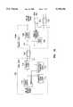
- FIG. 1Ais a functional block diagram of a computer system configured with a Universal Serial Bus and a self-powered remote USB hub as disclosed in one embodiment of the invention.
- FIG. 1Bis a functional block diagram of a computer system configured with a Universal Serial Bus and a self-powered remote USB function as disclosed in one embodiment of the invention.
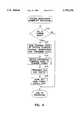
- FIG. 2is a logic flow diagram illustrating a procedure executed by the remote USB hub having an attached peripheral that generates an I/O event for processing by the computer of FIG. 1A.
- FIG. 3is a logic flow diagram illustrating a procedure that brings the computer of FIG. 1A back to full-power from a suspended state.
- FIG. 4is a logic flow diagram illustrating a procedure that places the computer of FIG. 1A into a suspended state.
- FIG. 5is a functional block diagram of a computer system configured with a Universal Serial Bus and suspend/resume function as disclosed in one embodiment of the invention.
- FIG. 6is a logic flow diagram illustrating a procedure that brings the computer of FIG. 5 back to full-power from a suspended state.
- USBUniversal Serial Bus
- the USB standardspecifies a transfer rate of up to 12 Mbps to support telephony, audio and compressed video data streams. It also establishes a universal cable connector which can provide power at various levels to peripherals attached to the bus. In addition, the USB standard defines a common logical interface for all types of peripherals that simplifies the design of supporting USB software and enables easy configuration of a system.
- the Universal Serial Busis logically comparable to the existing serial bus in that each device appears to have a direct connection to the computer, but it is physically configured as a "tiered star" network.
- a USB devicecalled a “hub” that serves as the bus connection point for other USB devices, either other hubs or “functions.”
- Functionsare generally standard computer peripherals which conform to the USB standard, or specialized circuitry designed to add certain functionality to the computer. Functions can be hardware, firmware, software, or a combination.
- Each hubhas multiple attachment points, known as "ports,” to which its functions and other hubs are connected by means of USB-specific cables. Hubs are interconnected to form a USB network containing up to 127 functions.
- All but the hub in the top tiercan be located external to the computer cabinet and are referred to as “remote” or “downstream” hubs.
- the remote hubscan be stand-alone units or embedded in USB peripherals. All hubs have a number of downstream ports used to attach functions or lower tier hubs, and a single "root” port that connects the hub to a hub in the next highest tier "upstream" in the USB network structure.
- the USB networkis controlled by the computer and its standard operating system software in conjunction with USB system software.
- the root hubis embedded in the computer and its root port provides the USB's physical interface to the computer.
- the combination of the computer, the standard operating system, the root hub, and the USB softwareis called a USB "host.”
- the USB networkperforms the standard functions of a communications bus by transferring data and commands from the computer's central processing unit (CPU) to the root hub which passes the information downstream to the appropriate remote hub that controls the receiving function and thence to the function itself. Signals from the function to the CPU retrace the same route in reverse, and traverse the network "upstream" to the host.
- CPUcentral processing unit
- Bus-powered hubsdraw all their power from their USB connection, while self-powered hubs draw theirs from an external power source, or a combination of both the external power source and the USB.
- Bus-powered and self-powered hubsboth provide power to devices attached to them.
- a bus-powered hubcan only re-distribute the amount of power it receives from its connection to the USB, and each downstream port on a bus-powered hub can supply a maximum of 100 mA to its attached device.
- a self-powered hubmust be able to supply 500 mA to each downstream device attached to the hub.
- the functionsare likewise divided into bus-powered and self-powered classes, with bus-powered functions further categorized as low-power and high-power.
- Low-power functionscan be powered from either type of hub, but high-power functions must be connected to self-powered hubs in order to have sufficient power to operate.
- Low-power functionsare generally peripherals such as a mouse or a keyboard; high-power functions include printers and speakers.
- Self-powered functionscan be attached to either type of hub as the function does not draw its operating power from the hub, although it can draw minimal power from the USB to support itself when in a suspended state.
- USB hubs and functionsmust enter a minimal power "suspend” state when they detect no I/O activity on their USB connections for a certain period of time.
- each hubis responsible for passing on a polling signal from the USB host to the devices attached to the hub to prevent them from suspending. Suspended hubs cannot transfer data on the bus until enabled by a "resume” command as discussed below.
- a suspend stateis triggered when the Universal Serial Bus is quiescent due to the USB host discontinuing all communication traffic, or because of a lack of I/O activity during certain types of computer operations.
- each hubdetects an idle condition on its root port for at least 3 ms it begins its suspend routine which includes terminating all signals to its downstream ports.
- the hubs in the next lower tierwill experience an idle condition and enter suspend mode, thus propagating the suspend state downward throughout the USB network.
- the functions attached to a suspended hubalso suspend upon detecting the idle condition.
- the systemexits the suspend state when a resume signal is issued either by the USB host and passed downstream through the network tiers, or when the internal logic of a suspended function initiates a "remote wakeup resume signal" to be sent upstream to the USB host.
- a resume signalis issued either by the USB host and passed downstream through the network tiers, or when the internal logic of a suspended function initiates a "remote wakeup resume signal" to be sent upstream to the USB host.
- an external eventsuch as the user typing a key or moving a mouse
- an internal eventsuch as the expiration of a timer
- the functionWhen the function is attached to a remote USB hub, it begins the resume process by sending a resume signal to its hub (the "re-enabling" hub).
- the re-enabling hubimmediately drives the resume signal through its root port upstream to the next highest tier, and downstream to its enabled ports and thus to the attached functions and lower tier hubs.
- the resume signalwakes up each hub in the path from the re-enabling hub to the root hub, and each hub drives the resume signal to its root and enabled downstream ports.
- the resume signalarrives at the USB host, the host takes control of the resume process by sending signals back downstream to resume the rest of the USB network and to notify the USB devices that the USB network is enabled.
- the re-enabling hubUpon receipt of the notification, the re-enabling hub sends the event signal from the function upstream for processing.
- An external event generated by a USB function attached to the USB host through the root hubcauses a resume process similar to that described above, except that the function drives the resume signal directly to the host.
- a personal computer system serving as a USB host 100contains a main power supply unit 118 coupled to a first power source, logic 112 that is powered down when the computer is suspended, such as read-only memory, graphics controllers, and internal peripheral connections, and logic 110 that is continually powered, such as main memory, real-time clock, and the central processing unit.
- logic 112 and 110are not limiting and it will be apparent to those of skill in the art that firmware, circuitry executing software, and hardware comprising the computer are eligible for inclusion in logic 112 or logic 110.
- the USB host 100also contains a USB root hub (not shown) which serves as the top-level attachment point for USB devices.
- the USB host 100is coupled to a self-powered remote USB device.
- the remote USB deviceis a USB hub 104A in FIG. 1A and a USB function 104B in FIG. 1B.
- Both USB devices 104A, 104Bcontain a remote power supply unit 108 coupled to a second power source, logic 106 specific to the type of the remote device, and a power gate 107, shown as a diode in FIG. 1A and 1B, that prevents power from flowing from the main power supply 118 to the remote device 104A, 104B but permits power from the remote power supply unit 108 to flow to the continually-powered logic 110 as explained below.
- the power supply units 108 and 118regulate the voltage supplied by the first and second power sources respectively.
- the first and second power sourcescan be batteries, AC wall current, or other well-known power sources.
- USB cables 102The connections between USB devices are represented as USB cables 102 in FIGS. 1A and 1B although it will be apparent to those of skill in the art that the Universal Serial Bus comprises the root hub in the USB host 100, the remote USB device 104A, 104B, and any additional USB devices downstream from the USB host 100, as well as the USB cables 102.
- USB cables 102contain four wires, two to transmit data, plus VBus and GND wires which deliver power to attached devices. Only VBus and GND wires are shown in FIGS. 1A and 1B.
- the expansion of the Universal Serial Bus with more remote hubs, additional attached functions, and the placement of the remote device further downstream from the USB host 100is contemplated by the invention and the operation of the expanded USB in accordance with the disclosure will be apparent to those skilled in the art.
- USB-compliant peripherals that generate external event signalsare attached downstream to the remote hub 104A which provides full, operating power to those USB peripheral(s) that are bus-powered through remote power supply unit 108.
- One way to connect the remote power supply unit 108 to the second power sourceis to embed the remote hub 104A in a USB peripheral which has a direct and continuous AC connection.
- the remote hub 104Ais placed near the USB peripheral(s) that generate external event signals (mouse, keyboard, modem, etc.) to minimize cable lengths between the peripherals and their attachment points on the hub 104A.
- the remote hub 104Ais embedded in a self-powered peripheral that is also near the computer, such as a set of external speakers.
- a self-powered peripheralsuch as a modem, are also good candidates to contain the remote hub 104A as will be apparent to those skilled in the art.
- the USB function 104Bis one of the USB peripherals that generate external event signals. Because the remote function 104B supplies stand-by power to the continually-powered logic 110 when the main power supply unit 118 is turned off, remote function 104B is a self-powered USB function. In one embodiment where the USB peripheral is large, such as a keyboard, the remote power supply unit 108 is embedded in the peripheral. In an alternate embodiment where the peripheral is a mouse, for example, the remote power supply unit 108 is located external to the USB peripheral.
- the continually-powered logic 110 in the USB host 100is coupled to the main power supply unit 118 through two separate connections.
- One connectionsupplies power to the circuitry executing the continually-powered logic 110 during normal operations.
- the continually-powered logic 110draws stand-by power through its attachment to the remote device 104A, 104B when the powered down logic 112 is in suspend mode and the main power supply unit 118 is turned off.
- the second connection between the continually-powered logic 110 and the main power supply unit 118enables the continually-powered logic 110 to turn on the main power supply unit 118 to return full power to the host 100 upon receiving a resume signal from the remote device 104A, 104B or the occurrence of an event in the continually-powered logic 110, such as expiration of a timer.
- Power logic 114is coupled to both the main power supply unit 118 and the remote power supply unit 108, and determines from which power supply unit the continually-power logic 110 draws its power.
- the power logic 114is implemented in firmware, but can be implemented as hardware, part of the USB system software, or in a combination of components in the computer as will be apparent to those skilled in the art.
- An external event directed to a USB peripheralcauses the execution of a process shown in FIG. 2.
- the processoperates slightly differently when the peripheral is active and when it is suspended, and also when the peripheral is attached to a USB remote hub as in FIG. 1A or is a remote function as in FIG. 1B.
- the USB peripheralWhen the USB peripheral is active (block 212), it processes the event signal and waits for the next poll from the USB host 100. The data is then transferred at block 218 to the USB host 100 when the USB peripheral is remote function 104B, or to the remote hub 104A which then drives the data through its root port to the USB host 100 when the USB peripheral is attached to remote hub 104A.
- the USB peripheralWhen the USB peripheral is suspended, it initiates remote wakeup resume signaling at block 214 and then waits (block 216) until it receives notice that the USB is fully awake before sending the data upstream (block 218).
- the resume signalWhen the USB peripheral is remote function 104B, the resume signal is sent directly to the continually-powered logic 110.
- the resume signalwakes-up the remote hub 104A.
- the remote hub 104Apasses the resume signal upstream to the continually-powered logic 110, and downstream to any additional attached USB devices (block 214).
- the receipt of the resume signal by the continually-powered logic 110triggers the process shown in FIG. 3.
- the main power supply unit 118is switched on by the continually-powered logic 110 at block 310 and the power logic 114 transfers the continually-powered logic 110 from remote power supply unit 108 to main power supply unit 118 (block 312).
- All suspended computer logic 112is then turned back on and the state of the system that was saved upon entry into suspend mode is also restored (block 314).
- the triggering eventis from USB peripheral (block 316)
- the now-active USB host 100re-enables the USB network as explained above.
- the resume processis now complete and the USB peripheral can transmit its event data to the host.
- the system suspend procedurefollows analogous logic, shown in FIG. 4, when power management software executing in host 100 determines the system should enter suspend mode (block 410).
- Power management softwareis typically implemented as part of the operating environment of the host 100, such as APM (Advanced Power Management) in Microsoft Windows 95 or 3.1, and is external to the Universal Serial Bus.
- APMAdvanced Power Management
- the USB system softwareintercepts APM suspend and resume commands.
- APMsaves the current state of the system and then powers down internal peripherals and logic 112 in the computer at block 412.
- the USB system softwareintercepts the suspend command and signals the power logic 114 to transfer the continually-powered logic 110 from the main power supply unit 118 to the stand-by remote power supply unit 108 (block 414).
- the USB system softwarenext terminates all USB traffic (block 416).
- the root hub in the USB host 100observes an idle condition on its root port for at least 3 ms, it suspends, and the suspend state propagates downward through the USB network to all the USB devices. After the requisite 3 ms of no I/O traffic, each downstream USB peripheral enters suspend mode as illustrated by blocks 210, 220 and 222 of FIG. 2.
- APMWhen APM detects the USB network is suspended, it switches off the main power supply unit 118 at block 418. At this point, all bus-powered USB devices that receive their power from the main power supply unit 118 via the USB are powered down. Self-powered USB devices, and downstream bus-powered USB functions that receive power from self-powered hubs, such as remote hub 104A, are suspended. The continually-powered logic 110, drawing power from the remote power supply unit 108, remains enabled so it may resume the USB host 100 when a wake-up event occurs.
- the USB host 100is configured with a root hub 506 and a suspend/resume function 510 as shown in block diagram form in FIG. 5.
- the suspend/resume function 510is described in terms of a software module executing in a portion of the circuitry of host 100, it will be apparent to those of skill in the art that it can also be implemented as a firmware program, or a logic circuit, or other similar apparatus.
- the USB network 502has two hubs coupled together: the root hub 506 and a self-powered remote hub 504.
- the root hub 506is further coupled to an data/address bus 514 so that it can pass data between the USB 502 and the central processing unit (CPU) 516 of the host 100.
- Peripherals that generate external event signalssuch as a keyboard, a mouse or a modem, are attached to the remote hub 504 and shown generically as USB peripheral 512.
- the remote hub 504provides full operating power to those USB peripheral(s) 512 that are bus-powered.
- USB 502with more remote hubs, additional attached functions, and the placement of the remote hub 504 further downstream from the root hub 506 is contemplated by the invention and the operation of the expanded USB in accordance with the disclosure will be apparent to those skilled in the art.
- the suspend/resume function 510is coupled to a power supply unit 518 through two separate connections. One connection supplies power to the circuitry executing the suspend/resume function 510 during normal operations.
- the suspend/resume function 510draws stand-by power through its attachment to one of the downstream ports of the remote hub 504 when the rest of the computer's circuitry is in a suspended state and the power supply unit 518 is turned off.
- the second connection between the suspend/resume function 510 and the power supply unit 518enables the suspend/resume function 510 to return full power to the host 100 upon receiving a resume signal from the remote hub 504 or the occurrence of an event in the suspend/resume function's internal logic.
- the suspend and resume processes for this embodimentoperate similarly to those shown in FIGS. 2 and 4 and described above in conjunction with a USB peripheral attached to remote hub 104A by substituting the suspend/resume function 510 for the continually-powered logic 110.
- the receipt of the resume signal by the suspend/resume function 510triggers a process shown in FIG. 6 that has different timing than that shown in FIG. 3.
- the power supply unit 518is switched on by suspend/resume function 510 at block 610. All suspended computer circuitry is then turned back on and the state of the system that was saved upon entry into suspend mode is also restored (block 612).
- the now-active host 100transfers the circuitry running the suspend/resume function 510 from stand-by power to the main power supply unit (block 614). Because the triggering event is from USB peripheral 512 (block 616), the USB is re-enabled by the resume signal as described in conjunction with FIG. 3.
- the resume processis now complete and the remote hub 504 can transmit its event data.
- an internal event in the suspend/resume function 510causes the procedure represented by block 622 to be executed in order to resume the USB network since the event did not originate from a USB peripheral.
- the suspend/resume function 510receives its main power as well as its stand-by power from the remote hub 504 and so is not switched to and from the power supply unit 518.
Landscapes
- Engineering & Computer Science (AREA)
- Theoretical Computer Science (AREA)
- General Engineering & Computer Science (AREA)
- Physics & Mathematics (AREA)
- General Physics & Mathematics (AREA)
- Computer Hardware Design (AREA)
- Power Sources (AREA)
Abstract
Description
The present invention is related to computer systems and in particular to power-saving functions for personal computers.
Many users of personal computers require that their computer be available to respond to internal or external events on a 24-hour basis. Until recently, those users had to leave their computers powered-on continuously, a practice which consumed unnecessary energy and also placed an excessive load on the computer's power supply unit. To offset these drawbacks while satisfying the demand for around-the-clock availability, computer vendors began offering a "sleep" or suspend mode, first on portable, and then on desktop computer systems. Suspend mode is a low-power state that uses only enough power to enable specialized suspend circuitry in the computer to monitor the computer's environment while the rest of the system is shut-down and drawing no power. When the suspend circuitry detects the occurrence of an internal event, such as an alarm, or an external event, such as an incoming modem call, it quickly resumes full power to the remainder of the computer.
One difficulty in implementing a suspend mode in a computer is providing the small amount of power required by the suspend circuitry. While the obvious solution is to use a single power supply unit designed to provide both full and low power, the reality is that such power units are generally expensive and suffer from poor efficiency at low power levels. Another solution equips the computer with two power supplies: one optimized for full power, the other for low power. However, this design has major drawbacks, in particular the added expense of providing two power supplies and the additional space taken in the computer cabinet by the power supply units.
What is needed, therefore, is an alternative low-power source which interfaces with existing power management software to satisfy the power needs of suspend/resume functions without the inefficiencies and expense of the current solutions.
A computer system receives stand-by power from a peripheral bus incorporating a power source independent of the main power supply unit of the computer system. A certain portion of the computer logic, including a power manager, is coupled to the main power supply unit and also to the peripheral bus. When the computer enters a suspend mode, the power manager shuts down the main power supply unit but remains active by drawing stand-by power from the peripheral bus. When an event occurs that requires processing by the computer, the power manager turns on the main power supply unit to resume full computer operations.
Existing serial and parallel peripheral buses built into most personal computer systems can route power from the main power supply of the computer to peripherals connected to them. However, the existing buses cannot provide stand-by power to peripherals when the computer is in suspend mode because the main power supply is off, but a bus that draws power from a source independent of the main power supply can provide stand-by power.
Recently, a consortium of computer vendors proposed a new type of bus structure to replace the existing serial peripheral bus. The Universal Serial Bus (USB) open-architecture standard specifies USB devices known as "hubs" that provide attachment points for other USB devices, such as USB-compliant peripherals (called "functions") or additional hubs. Self-powered hubs and functions contain independent power supplies to power themselves, and self-powered hubs can also power any other devices attached to them. A "root" hub embedded in the computer routes data between the USB peripherals and the appropriate processing logic in the computer. The standard also defines USB software that works with current power management software to enable the suspending and resuming of devices attached to the Universal Serial Bus in response to the state of the computer. The combination of the computer, the standard operating system, the root hub, and the USB software is called a USB "host."
A USB host in the subject invention is coupled to a remote USB device located external to the computer. A first power source is coupled to a main power supply unit to provide power for the computer while the remote device receives power from a remote power supply unit coupled to a second power source. The host contains two types of logic: logic which can be powered down and logic which must be continually powered. Both types of logic are coupled to the main power supply unit so that they draw power from the first power source when the computer is operating normally. The continually-powered logic is also coupled to a control switch on the main power supply unit and further coupled to the remote power supply unit. When the computer enters suspend mode, the main power supply unit is turned off but the continually-powered logic remains active by drawing power from the second power source. When an external event occurs that requires processing by the computer, the remote USB device signals the continually-powered logic which then switches on the main power supply unit to resume the powered down logic.
The remote USB device can be either a USB hub or a USB function. When the remote device is a USB hub, the external event is generated by a USB function (peripheral) attached to the hub, such as a keyboard or a mouse. When the remote device is a USB function, the function itself generates the external event that resumes the computer.
Furthermore, when the remote device is a USB hub, specialized suspend/resume circuitry can be located in the computer and coupled to the remote hub. The suspend/resume circuitry comprises a first USB function that draws its power from the second power source. The suspend/resume function is further coupled to the control switch on the main power supply unit. A second USB function, such as a keyboard or mouse, which is also coupled to the USB through the remote hub, provides input data to the computer. When the computer is in suspend mode, input data generated by the second USB function sends a signal on the Universal Serial Bus which causes the suspend/resume function to turn on the main power supply unit so that the computer receives power and resumes full operation.
Combining the ability of the Universal Serial Bus to provide an alternative low power source with existing power management software that controls the computer's main power supply unit provides a superior solution to supplying the power needs of suspend/resume capabilities in a computer without the inefficiencies of a dual-stage power supply unit or the expense of incorporating both low-power and full-power units.
FIG. 1A is a functional block diagram of a computer system configured with a Universal Serial Bus and a self-powered remote USB hub as disclosed in one embodiment of the invention.
FIG. 1B is a functional block diagram of a computer system configured with a Universal Serial Bus and a self-powered remote USB function as disclosed in one embodiment of the invention.
FIG. 2 is a logic flow diagram illustrating a procedure executed by the remote USB hub having an attached peripheral that generates an I/O event for processing by the computer of FIG. 1A.
FIG. 3 is a logic flow diagram illustrating a procedure that brings the computer of FIG. 1A back to full-power from a suspended state.
FIG. 4 is a logic flow diagram illustrating a procedure that places the computer of FIG. 1A into a suspended state.
FIG. 5 is a functional block diagram of a computer system configured with a Universal Serial Bus and suspend/resume function as disclosed in one embodiment of the invention.
FIG. 6 is a logic flow diagram illustrating a procedure that brings the computer of FIG. 5 back to full-power from a suspended state.
In the following detailed description of the embodiments, reference is made to the accompanying drawings which form a part hereof, and in which is shown by way of illustration specific embodiments in which the invention may be practiced. These embodiments are described in sufficient detail to enable those skilled in the art to practice the invention, and it is to be understood that other embodiments may be utilized and that structural, logical and electrical changes may be made without departing from the spirit and scope of the present inventions. The following detailed description is, therefore, not to be taken in a limiting sense, and the scope of the present inventions is defined only by the appended claims.
Numbering in the Figures is usually done with the hundreds digits corresponding to the figure number, with the exception that identical components which appear in multiple figures are identified by the same reference numbers. Signals and connections may be referred to by the same number or label, and the actual meaning should be clear from the context of use.
The Universal Serial Bus (USB) open-architecture standard was developed to alleviate the shortcomings of the existing serial bus interface that connects external peripherals to a personal computer. The standard serial bus cannot sustain the faster data transfer rates required by newer technologies such as audio and video. Furthermore, the existing serial bus must support many different physical connections for the great variety of peripherals that connect to it and must contend with multiple logical interfaces for such devices, making system configuration difficult.
The USB standard specifies a transfer rate of up to 12 Mbps to support telephony, audio and compressed video data streams. It also establishes a universal cable connector which can provide power at various levels to peripherals attached to the bus. In addition, the USB standard defines a common logical interface for all types of peripherals that simplifies the design of supporting USB software and enables easy configuration of a system.
The Universal Serial Bus is logically comparable to the existing serial bus in that each device appears to have a direct connection to the computer, but it is physically configured as a "tiered star" network. At the center of each star is a USB device called a "hub" that serves as the bus connection point for other USB devices, either other hubs or "functions." Functions are generally standard computer peripherals which conform to the USB standard, or specialized circuitry designed to add certain functionality to the computer. Functions can be hardware, firmware, software, or a combination. Each hub has multiple attachment points, known as "ports," to which its functions and other hubs are connected by means of USB-specific cables. Hubs are interconnected to form a USB network containing up to 127 functions.
All but the hub in the top tier (the "root" hub) can be located external to the computer cabinet and are referred to as "remote" or "downstream" hubs. The remote hubs can be stand-alone units or embedded in USB peripherals. All hubs have a number of downstream ports used to attach functions or lower tier hubs, and a single "root" port that connects the hub to a hub in the next highest tier "upstream" in the USB network structure.
The USB network is controlled by the computer and its standard operating system software in conjunction with USB system software. The root hub is embedded in the computer and its root port provides the USB's physical interface to the computer. The combination of the computer, the standard operating system, the root hub, and the USB software is called a USB "host." The USB network performs the standard functions of a communications bus by transferring data and commands from the computer's central processing unit (CPU) to the root hub which passes the information downstream to the appropriate remote hub that controls the receiving function and thence to the function itself. Signals from the function to the CPU retrace the same route in reverse, and traverse the network "upstream" to the host.
Remote hubs are of two basic types: bus-powered and self-powered. Bus-powered hubs draw all their power from their USB connection, while self-powered hubs draw theirs from an external power source, or a combination of both the external power source and the USB. Bus-powered and self-powered hubs both provide power to devices attached to them. However, a bus-powered hub can only re-distribute the amount of power it receives from its connection to the USB, and each downstream port on a bus-powered hub can supply a maximum of 100 mA to its attached device. A self-powered hub must be able to supply 500 mA to each downstream device attached to the hub.
The functions are likewise divided into bus-powered and self-powered classes, with bus-powered functions further categorized as low-power and high-power. Low-power functions can be powered from either type of hub, but high-power functions must be connected to self-powered hubs in order to have sufficient power to operate. Low-power functions are generally peripherals such as a mouse or a keyboard; high-power functions include printers and speakers. Self-powered functions can be attached to either type of hub as the function does not draw its operating power from the hub, although it can draw minimal power from the USB to support itself when in a suspended state.
All USB hubs and functions must enter a minimal power "suspend" state when they detect no I/O activity on their USB connections for a certain period of time. During normal operations, each hub is responsible for passing on a polling signal from the USB host to the devices attached to the hub to prevent them from suspending. Suspended hubs cannot transfer data on the bus until enabled by a "resume" command as discussed below.
A suspend state is triggered when the Universal Serial Bus is quiescent due to the USB host discontinuing all communication traffic, or because of a lack of I/O activity during certain types of computer operations. When each hub detects an idle condition on its root port for at least 3 ms it begins its suspend routine which includes terminating all signals to its downstream ports. As each network tier is suspended, the hubs in the next lower tier will experience an idle condition and enter suspend mode, thus propagating the suspend state downward throughout the USB network. The functions attached to a suspended hub also suspend upon detecting the idle condition.
The system exits the suspend state when a resume signal is issued either by the USB host and passed downstream through the network tiers, or when the internal logic of a suspended function initiates a "remote wakeup resume signal" to be sent upstream to the USB host. In the latter case, an external event, such as the user typing a key or moving a mouse, or an internal event, such as the expiration of a timer, awakens the corresponding function. Since a USB function is only suspended when its section of the USB network is suspended, the appropriate section of the USB network must be resumed before the function can send the event data to the USB host for processing.
When the function is attached to a remote USB hub, it begins the resume process by sending a resume signal to its hub (the "re-enabling" hub). The re-enabling hub immediately drives the resume signal through its root port upstream to the next highest tier, and downstream to its enabled ports and thus to the attached functions and lower tier hubs. The resume signal wakes up each hub in the path from the re-enabling hub to the root hub, and each hub drives the resume signal to its root and enabled downstream ports. When the resume signal arrives at the USB host, the host takes control of the resume process by sending signals back downstream to resume the rest of the USB network and to notify the USB devices that the USB network is enabled. Upon receipt of the notification, the re-enabling hub sends the event signal from the function upstream for processing.
An external event generated by a USB function attached to the USB host through the root hub causes a resume process similar to that described above, except that the function drives the resume signal directly to the host.
A personal computer system serving as aUSB host 100, as shown in block diagram form in FIGS. 1A and 1B, contains a mainpower supply unit 118 coupled to a first power source,logic 112 that is powered down when the computer is suspended, such as read-only memory, graphics controllers, and internal peripheral connections, andlogic 110 that is continually powered, such as main memory, real-time clock, and the central processing unit. The examples given forlogic logic 112 orlogic 110.
TheUSB host 100 also contains a USB root hub (not shown) which serves as the top-level attachment point for USB devices. TheUSB host 100 is coupled to a self-powered remote USB device. The remote USB device is aUSB hub 104A in FIG. 1A and aUSB function 104B in FIG. 1B. BothUSB devices power supply unit 108 coupled to a second power source,logic 106 specific to the type of the remote device, and apower gate 107, shown as a diode in FIG. 1A and 1B, that prevents power from flowing from themain power supply 118 to theremote device power supply unit 108 to flow to the continually-poweredlogic 110 as explained below. Thepower supply units
The connections between USB devices are represented asUSB cables 102 in FIGS. 1A and 1B although it will be apparent to those of skill in the art that the Universal Serial Bus comprises the root hub in theUSB host 100, theremote USB device USB host 100, as well as theUSB cables 102.USB cables 102 contain four wires, two to transmit data, plus VBus and GND wires which deliver power to attached devices. Only VBus and GND wires are shown in FIGS. 1A and 1B. The expansion of the Universal Serial Bus with more remote hubs, additional attached functions, and the placement of the remote device further downstream from theUSB host 100 is contemplated by the invention and the operation of the expanded USB in accordance with the disclosure will be apparent to those skilled in the art.
In FIG. 1A, USB-compliant peripherals that generate external event signals, such as a keyboard, a mouse or a modem, are attached downstream to theremote hub 104A which provides full, operating power to those USB peripheral(s) that are bus-powered through remotepower supply unit 108. One way to connect the remotepower supply unit 108 to the second power source is to embed theremote hub 104A in a USB peripheral which has a direct and continuous AC connection. In one embodiment, theremote hub 104A is placed near the USB peripheral(s) that generate external event signals (mouse, keyboard, modem, etc.) to minimize cable lengths between the peripherals and their attachment points on thehub 104A. Since these types of USB peripherals are usually located near the computer cabinet, in this embodiment theremote hub 104A is embedded in a self-powered peripheral that is also near the computer, such as a set of external speakers. Other self-powered peripherals, such as a modem, are also good candidates to contain theremote hub 104A as will be apparent to those skilled in the art.
In FIG. 1B, theUSB function 104B is one of the USB peripherals that generate external event signals. Because theremote function 104B supplies stand-by power to the continually-poweredlogic 110 when the mainpower supply unit 118 is turned off,remote function 104B is a self-powered USB function. In one embodiment where the USB peripheral is large, such as a keyboard, the remotepower supply unit 108 is embedded in the peripheral. In an alternate embodiment where the peripheral is a mouse, for example, the remotepower supply unit 108 is located external to the USB peripheral.
The continually-poweredlogic 110 in theUSB host 100 is coupled to the mainpower supply unit 118 through two separate connections. One connection supplies power to the circuitry executing the continually-poweredlogic 110 during normal operations. The continually-poweredlogic 110 draws stand-by power through its attachment to theremote device logic 112 is in suspend mode and the mainpower supply unit 118 is turned off. The second connection between the continually-poweredlogic 110 and the mainpower supply unit 118 enables the continually-poweredlogic 110 to turn on the mainpower supply unit 118 to return full power to thehost 100 upon receiving a resume signal from theremote device logic 110, such as expiration of a timer.Power logic 114 is coupled to both the mainpower supply unit 118 and the remotepower supply unit 108, and determines from which power supply unit the continually-power logic 110 draws its power. In this embodiment, thepower logic 114 is implemented in firmware, but can be implemented as hardware, part of the USB system software, or in a combination of components in the computer as will be apparent to those skilled in the art.
An external event directed to a USB peripheral, such as a keystroke, a mouse movement, or a modem ring, causes the execution of a process shown in FIG. 2. The process operates slightly differently when the peripheral is active and when it is suspended, and also when the peripheral is attached to a USB remote hub as in FIG. 1A or is a remote function as in FIG. 1B.
When the USB peripheral is active (block 212), it processes the event signal and waits for the next poll from theUSB host 100. The data is then transferred at block 218 to theUSB host 100 when the USB peripheral isremote function 104B, or to theremote hub 104A which then drives the data through its root port to theUSB host 100 when the USB peripheral is attached toremote hub 104A.
When the USB peripheral is suspended, it initiates remote wakeup resume signaling atblock 214 and then waits (block 216) until it receives notice that the USB is fully awake before sending the data upstream (block 218). When the USB peripheral isremote function 104B, the resume signal is sent directly to the continually-poweredlogic 110. When the USB peripheral is attached to theremote hub 104A, the resume signal wakes-up theremote hub 104A. Theremote hub 104A passes the resume signal upstream to the continually-poweredlogic 110, and downstream to any additional attached USB devices (block 214).
The receipt of the resume signal by the continually-poweredlogic 110 triggers the process shown in FIG. 3. First, the mainpower supply unit 118 is switched on by the continually-poweredlogic 110 atblock 310 and thepower logic 114 transfers the continually-poweredlogic 110 from remotepower supply unit 108 to main power supply unit 118 (block 312). All suspendedcomputer logic 112 is then turned back on and the state of the system that was saved upon entry into suspend mode is also restored (block 314). Because the triggering event is from USB peripheral (block 316), the now-active USB host 100 re-enables the USB network as explained above. The resume process is now complete and the USB peripheral can transmit its event data to the host.
If an internal event in the continually-poweredlogic 110, such as an alarm, triggers a resume, the same logic in FIG. 3 is followed, except that the procedure represented byblock 322 must be executed in order to resume the USB network since the event did not originate from a USB peripheral.
The system suspend procedure follows analogous logic, shown in FIG. 4, when power management software executing inhost 100 determines the system should enter suspend mode (block 410). Power management software is typically implemented as part of the operating environment of thehost 100, such as APM (Advanced Power Management) in Microsoft Windows 95 or 3.1, and is external to the Universal Serial Bus. However, the USB system software intercepts APM suspend and resume commands. When initiating a suspend state, APM saves the current state of the system and then powers down internal peripherals andlogic 112 in the computer atblock 412.
The USB system software intercepts the suspend command and signals thepower logic 114 to transfer the continually-poweredlogic 110 from the mainpower supply unit 118 to the stand-by remote power supply unit 108 (block 414). The USB system software next terminates all USB traffic (block 416). When the root hub in theUSB host 100 observes an idle condition on its root port for at least 3 ms, it suspends, and the suspend state propagates downward through the USB network to all the USB devices. After the requisite 3 ms of no I/O traffic, each downstream USB peripheral enters suspend mode as illustrated byblocks
When APM detects the USB network is suspended, it switches off the mainpower supply unit 118 atblock 418. At this point, all bus-powered USB devices that receive their power from the mainpower supply unit 118 via the USB are powered down. Self-powered USB devices, and downstream bus-powered USB functions that receive power from self-powered hubs, such asremote hub 104A, are suspended. The continually-poweredlogic 110, drawing power from the remotepower supply unit 108, remains enabled so it may resume theUSB host 100 when a wake-up event occurs.
In an alternate embodiment, theUSB host 100 is configured with aroot hub 506 and a suspend/resume function 510 as shown in block diagram form in FIG. 5. Although the suspend/resume function 510 is described in terms of a software module executing in a portion of the circuitry ofhost 100, it will be apparent to those of skill in the art that it can also be implemented as a firmware program, or a logic circuit, or other similar apparatus.
TheUSB network 502 has two hubs coupled together: theroot hub 506 and a self-poweredremote hub 504. Theroot hub 506 is further coupled to an data/address bus 514 so that it can pass data between theUSB 502 and the central processing unit (CPU) 516 of thehost 100. Peripherals that generate external event signals, such as a keyboard, a mouse or a modem, are attached to theremote hub 504 and shown generically asUSB peripheral 512. Theremote hub 504 provides full operating power to those USB peripheral(s) 512 that are bus-powered. The expansion of theUSB 502 with more remote hubs, additional attached functions, and the placement of theremote hub 504 further downstream from theroot hub 506 is contemplated by the invention and the operation of the expanded USB in accordance with the disclosure will be apparent to those skilled in the art.
The suspend/resume function 510 is coupled to apower supply unit 518 through two separate connections. One connection supplies power to the circuitry executing the suspend/resume function 510 during normal operations. The suspend/resume function 510 draws stand-by power through its attachment to one of the downstream ports of theremote hub 504 when the rest of the computer's circuitry is in a suspended state and thepower supply unit 518 is turned off. The second connection between the suspend/resume function 510 and thepower supply unit 518 enables the suspend/resume function 510 to return full power to thehost 100 upon receiving a resume signal from theremote hub 504 or the occurrence of an event in the suspend/resume function's internal logic.
The suspend and resume processes for this embodiment operate similarly to those shown in FIGS. 2 and 4 and described above in conjunction with a USB peripheral attached toremote hub 104A by substituting the suspend/resume function 510 for the continually-poweredlogic 110.
The receipt of the resume signal by the suspend/resume function 510 triggers a process shown in FIG. 6 that has different timing than that shown in FIG. 3. First, thepower supply unit 518 is switched on by suspend/resume function 510 atblock 610. All suspended computer circuitry is then turned back on and the state of the system that was saved upon entry into suspend mode is also restored (block 612). The now-active host 100 transfers the circuitry running the suspend/resume function 510 from stand-by power to the main power supply unit (block 614). Because the triggering event is from USB peripheral 512 (block 616), the USB is re-enabled by the resume signal as described in conjunction with FIG. 3. The resume process is now complete and theremote hub 504 can transmit its event data.
As before, an internal event in the suspend/resume function 510 causes the procedure represented byblock 622 to be executed in order to resume the USB network since the event did not originate from a USB peripheral.
In a further alternate embodiment, the suspend/resume function 510 receives its main power as well as its stand-by power from theremote hub 504 and so is not switched to and from thepower supply unit 518.
It is to be understood that the above description is intended to be illustrative, and not restrictive. Many other embodiments will be apparent to those of skill in the art upon reviewing the above description. The scope of the invention should, therefore, be determined with reference to the appended claims, along with the full scope of equivalents to which such claims are entitled.
Claims (17)
1. A computer system coupled to a peripheral bus incorporating a power source therein, the computer system comprising:
a central processing unit;
a power supply unit coupled to a power source and coupled to the central processing unit wherein the central processing unit draws power from the power supply unit during normal operation of the computer; and
a power manager coupled to the incorporated power source and to the power supply unit to shut down the power supply unit, and to monitor the computer system using power supplied by the incorporated power source when the computer system is in a suspend mode.
2. The computer system of claim 1 wherein the central processing unit and the power manager are coupled to a data/address bus.
3. The computer system of claim 2 wherein the power manager monitors activity on the data/address bus.
4. The computer system of claim 3 wherein an input peripheral is coupled to the data/address bus, and input therefrom causes the power manager to resume normal operation of the computer system.
5. The computer system of claim 1 wherein the power manager receives power from the power supply unit during normal operation of the computer system.
6. A computer system with suspend and resume modes comprising:
a host computer having logic coupled to a main power supply unit, wherein the main power supply unit is further coupled to a first power source wherein the main power supply unit supplies power to the host computer logic during normal operations; and
a Universal Serial Bus remote device coupled to the host computer logic and having a remote power supply unit coupled to a second power source, wherein the remote power supply unit supplies power to the host computer logic when the host computer is in suspend mode.
7. The computer system of claim 6, wherein the remote device is a Universal Serial Bus hub.
8. The computer system of claim 7, further comprising a Universal Serial Bus function coupled to the Universal Serial Bus remote hub so that the Universal Serial Bus function directs the host computer logic to turn on the main power supply unit to provide power from the first power source to the host computer to resume normal operations.
9. The computer system of claim 6, wherein the remote device is a Universal Serial Bus function that directs the host computer logic to turn on the main power supply unit to provide power from the first power source to the host computer to resume normal operations.
10. The computer system of claim 6, wherein the host computer logic comprises:
logic that is powered down when the host computer is in suspend mode; and
logic that is continually powered by the second power source when the host computer is in suspend mode so that the continually powered logic can direct the main power supply unit to provide power from the first power source to the powered down logic to resume normal operations.
11. A computer system with suspend and resume modes comprising:
a host computer having a central processing unit coupled to a data/address bus and further coupled to a power supply unit, wherein the power supply unit is further coupled to a first power source to supply power to the host computer;
a Universal Serial Bus communicatively coupled to the data/address bus and further coupled to a second power source to supply power to the Universal Serial Bus;
first and second functions communicately coupled to the Universal Serial Bus, wherein the first and second functions draw power from the second power source; and
the second function further coupled to the power supply unit whereby a signal sent from the first function on the Universal Serial Bus causes the second function to direct the power supply unit to provide power from the first power source to the host computer.
12. The computer system of claim 11, wherein the Universal Serial Bus comprises:
a Universal Serial Bus root hub communicately coupled to the data/address bus of the host computer; and
a Universal Serial Bus remote hub communicately coupled to the Universal Serial Bus root hub and further coupled to the second power source.
13. The computer system of claim 12, wherein the remote hub is physically located external to the host computer.
14. The computer system of claim 12, wherein the first function is an input peripheral communicately coupled to the remote hub and the second function is suspend/resume circuitry communicately coupled to the remote hub.
15. The computer system of claim 14, wherein the suspend/resume circuitry receives power from the first power source through its connection to the power supply unit.
16. The computer system of claim 14, wherein the suspend/resume circuitry is further communicately coupled to the data/address bus so that it can receive data from the central processing unit.
17. A method of controlling the source of power used for a computer system having a suspend mode and a normal mode comprising the steps of:
receiving AC power from a main power source;
converting the AC power to DC power by means of a power supply unit wherein the computer system draws the DC power from the power supply in normal mode;
receiving DC power from a power supply incorporated into a peripheral bus via the peripheral bus;
shutting down the power supply unit when the computer enters suspend mode; and
monitoring computer system activity using circuitry receiving the DC power from the peripheral bus.
Priority Applications (1)
| Application Number | Priority Date | Filing Date | Title |
|---|---|---|---|
| US08/677,325US5799196A (en) | 1996-07-02 | 1996-07-02 | Method and apparatus of providing power management using a self-powered universal serial bus (USB) device |
Applications Claiming Priority (1)
| Application Number | Priority Date | Filing Date | Title |
|---|---|---|---|
| US08/677,325US5799196A (en) | 1996-07-02 | 1996-07-02 | Method and apparatus of providing power management using a self-powered universal serial bus (USB) device |
Publications (1)
| Publication Number | Publication Date |
|---|---|
| US5799196Atrue US5799196A (en) | 1998-08-25 |
Family
ID=24718237
Family Applications (1)
| Application Number | Title | Priority Date | Filing Date |
|---|---|---|---|
| US08/677,325Expired - LifetimeUS5799196A (en) | 1996-07-02 | 1996-07-02 | Method and apparatus of providing power management using a self-powered universal serial bus (USB) device |
Country Status (1)
| Country | Link |
|---|---|
| US (1) | US5799196A (en) |
Cited By (150)
| Publication number | Priority date | Publication date | Assignee | Title |
|---|---|---|---|---|
| US5903777A (en)* | 1997-10-02 | 1999-05-11 | National Semiconductor Corp. | Increasing the availability of the universal serial bus interconnects |
| US6009529A (en)* | 1997-04-14 | 1999-12-28 | Samsung Electronics Co., Ltd. | Method of realizing DPMS function of display device using USB |
| US6065053A (en) | 1997-10-01 | 2000-05-16 | Micron Electronics, Inc. | System for resetting a server |
| US6067628A (en)* | 1998-04-09 | 2000-05-23 | Intel Corporation | Method to monitor universal serial bus hub overcurrent |
| US6073255A (en) | 1997-05-13 | 2000-06-06 | Micron Electronics, Inc. | Method of reading system log |
| US6088816A (en) | 1997-10-01 | 2000-07-11 | Micron Electronics, Inc. | Method of displaying system status |
| US6122758A (en) | 1997-05-13 | 2000-09-19 | Micron Electronics, Inc. | System for mapping environmental resources to memory for program access |
| US6128732A (en)* | 1997-12-15 | 2000-10-03 | Compaq Computer Corporation | Implementing universal serial bus support with a minimum of system RAM |
| US6128743A (en)* | 1998-09-28 | 2000-10-03 | Pertech, Inc. | Intelligent system and method for universal bus communication and power |
| US6134673A (en) | 1997-05-13 | 2000-10-17 | Micron Electronics, Inc. | Method for clustering software applications |
| US6134668A (en) | 1997-05-13 | 2000-10-17 | Micron Electronics, Inc. | Method of selective independent powering of portion of computer system through remote interface from remote interface power supply |
| US6138250A (en) | 1997-05-13 | 2000-10-24 | Micron Electronics, Inc. | System for reading system log |
| US6138179A (en) | 1997-10-01 | 2000-10-24 | Micron Electronics, Inc. | System for automatically partitioning and formatting a primary hard disk for installing software in which selection of extended partition size is not related to size of hard disk |
| WO2000041496A3 (en)* | 1999-01-12 | 2000-11-02 | Powerdsine Ltd | Structured cabling system providing electrical power and data communications simultaneously |
| US6145098A (en) | 1997-05-13 | 2000-11-07 | Micron Electronics, Inc. | System for displaying system status |
| US6151652A (en)* | 1997-06-27 | 2000-11-21 | Canon Kabushiki Kaisha | I/O card, electronic equipment using I/O card, and procedure of starting up such electronic equipment |
| US6154835A (en) | 1997-10-01 | 2000-11-28 | Micron Electronics, Inc. | Method for automatically configuring and formatting a computer system and installing software |
| US6163849A (en) | 1997-05-13 | 2000-12-19 | Micron Electronics, Inc. | Method of powering up or powering down a server to a maintenance state |
| US6163853A (en) | 1997-05-13 | 2000-12-19 | Micron Electronics, Inc. | Method for communicating a software-generated pulse waveform between two servers in a network |
| US6170067B1 (en) | 1997-05-13 | 2001-01-02 | Micron Technology, Inc. | System for automatically reporting a system failure in a server |
| US6170028B1 (en) | 1997-05-13 | 2001-01-02 | Micron Electronics, Inc. | Method for hot swapping a programmable network adapter by using a programmable processor to selectively disabling and enabling power thereto upon receiving respective control signals |
| US6173346B1 (en) | 1997-05-13 | 2001-01-09 | Micron Electronics, Inc. | Method for hot swapping a programmable storage adapter using a programmable processor for selectively enabling or disabling power to adapter slot in response to respective request signals |
| US6178514B1 (en)* | 1998-07-31 | 2001-01-23 | Bradley C. Wood | Method and apparatus for connecting a device to a bus carrying power and a signal |
| US6179486B1 (en) | 1997-05-13 | 2001-01-30 | Micron Electronics, Inc. | Method for hot add of a mass storage adapter on a system including a dynamically loaded adapter driver |
| US6182180B1 (en) | 1997-05-13 | 2001-01-30 | Micron Electronics, Inc. | Apparatus for interfacing buses |
| US6189109B1 (en) | 1997-05-13 | 2001-02-13 | Micron Electronics, Inc. | Method of remote access and control of environmental conditions |
| US6192434B1 (en) | 1997-05-13 | 2001-02-20 | Micron Electronics, Inc | System for hot swapping a programmable adapter by using a programmable processor to selectively disabling and enabling power thereto upon receiving respective control signals |
| US6195717B1 (en) | 1997-05-13 | 2001-02-27 | Micron Electronics, Inc. | Method of expanding bus loading capacity |
| US6199173B1 (en) | 1997-10-01 | 2001-03-06 | Micron Electronics, Inc. | Method for mapping environmental resources to memory for program access |
| US6202111B1 (en) | 1997-05-13 | 2001-03-13 | Micron Electronics, Inc. | Method for the hot add of a network adapter on a system including a statically loaded adapter driver |
| US6202160B1 (en) | 1997-05-13 | 2001-03-13 | Micron Electronics, Inc. | System for independent powering of a computer system |
| US6205503B1 (en) | 1998-07-17 | 2001-03-20 | Mallikarjunan Mahalingam | Method for the hot swap and add of input/output platforms and devices |
| WO2001020433A1 (en)* | 1999-09-14 | 2001-03-22 | Infineon Technologies Ag | Device and method for supplying power to computer peripheral equipment using the bus system of the computer |
| US6212585B1 (en) | 1997-10-01 | 2001-04-03 | Micron Electronics, Inc. | Method of automatically configuring a server after hot add of a device |
| US6219734B1 (en) | 1997-05-13 | 2001-04-17 | Micron Electronics, Inc. | Method for the hot add of a mass storage adapter on a system including a statically loaded adapter driver |
| US6223234B1 (en) | 1998-07-17 | 2001-04-24 | Micron Electronics, Inc. | Apparatus for the hot swap and add of input/output platforms and devices |
| US6230226B1 (en)* | 1997-09-30 | 2001-05-08 | Intel Corporation | Compound device implementing hub and function endpoints on a single chip |
| US6243838B1 (en) | 1997-05-13 | 2001-06-05 | Micron Electronics, Inc. | Method for automatically reporting a system failure in a server |
| US6243773B1 (en) | 1997-05-13 | 2001-06-05 | Micron Electronics, Inc. | Configuration management system for hot adding and hot replacing devices |
| US6247079B1 (en) | 1997-05-13 | 2001-06-12 | Micron Electronics, Inc | Apparatus for computer implemented hot-swap and hot-add |
| US6247080B1 (en) | 1997-05-13 | 2001-06-12 | Micron Electronics, Inc. | Method for the hot add of devices |
| US6249828B1 (en) | 1997-05-13 | 2001-06-19 | Micron Electronics, Inc. | Method for the hot swap of a mass storage adapter on a system including a statically loaded adapter driver |
| US6249834B1 (en) | 1997-05-13 | 2001-06-19 | Micron Technology, Inc. | System for expanding PCI bus loading capacity |
| US6249885B1 (en) | 1997-05-13 | 2001-06-19 | Karl S. Johnson | Method for managing environmental conditions of a distributed processor system |
| US6253329B1 (en)* | 1998-01-16 | 2001-06-26 | Samsung Electronics Co., Ltd. | Universal serial bus (USB) hub having a plurality of input power sources |
| US6253334B1 (en) | 1997-05-13 | 2001-06-26 | Micron Electronics, Inc. | Three bus server architecture with a legacy PCI bus and mirrored I/O PCI buses |
| US6263387B1 (en) | 1997-10-01 | 2001-07-17 | Micron Electronics, Inc. | System for automatically configuring a server after hot add of a device |
| US20010009027A1 (en)* | 2000-01-17 | 2001-07-19 | Alps Electric Co., Ltd. | Computer power supply startup apparatus |
| US6269417B1 (en) | 1997-05-13 | 2001-07-31 | Micron Technology, Inc. | Method for determining and displaying the physical slot number of an expansion bus device |
| US6269412B1 (en) | 1997-05-13 | 2001-07-31 | Micron Technology, Inc. | Apparatus for recording information system events |
| US6272645B1 (en)* | 1998-08-12 | 2001-08-07 | Windbond Electronics Corp. | Method and control circuit for waking up a computer system from standby mode |
| US6275375B1 (en)* | 1997-01-10 | 2001-08-14 | Samsung Electronics Co., Ltd. | Monitor stand with hub mount |
| US6282673B1 (en) | 1997-05-13 | 2001-08-28 | Micron Technology, Inc. | Method of recording information system events |
| US6292905B1 (en) | 1997-05-13 | 2001-09-18 | Micron Technology, Inc. | Method for providing a fault tolerant network using distributed server processes to remap clustered network resources to other servers during server failure |
| US6304929B1 (en) | 1997-05-13 | 2001-10-16 | Micron Electronics, Inc. | Method for hot swapping a programmable adapter by using a programmable processor to selectively disabling and enabling power thereto upon receiving respective control signals |
| US6308278B1 (en)* | 1997-12-29 | 2001-10-23 | Intel Corporation | Supplying standby voltage to memory and wakeup circuitry to wake a computer from a low power mode |
| US6324608B1 (en) | 1997-05-13 | 2001-11-27 | Micron Electronics | Method for hot swapping of network components |
| US6330690B1 (en) | 1997-05-13 | 2001-12-11 | Micron Electronics, Inc. | Method of resetting a server |
| US6334160B1 (en) | 1999-01-28 | 2001-12-25 | Hewlett-Packard Co. | Apparatus and method for providing multiple protocols through a common connector in a device |
| US6341322B1 (en) | 1997-05-13 | 2002-01-22 | Micron Electronics, Inc. | Method for interfacing two buses |
| WO2001080026A3 (en)* | 2000-04-18 | 2002-01-24 | Digi Int Inc | Bus control module |
| US6345364B1 (en) | 1998-04-11 | 2002-02-05 | Samsung Electronics Co., Ltd. | Power supply of display apparatus with universal serial bus device |
| WO2001025886A3 (en)* | 1999-10-07 | 2002-02-14 | Intel Corp | Power management method for a computer system having a hub interface architecture |
| US6357011B2 (en)* | 1998-07-15 | 2002-03-12 | Gateway, Inc. | Bus-powered computer peripheral with supplement battery power to overcome bus-power limit |
| US20020062416A1 (en)* | 2000-11-17 | 2002-05-23 | Moon-Kyou Kim | Portable computer system and control method thereof |
| US6408351B1 (en)* | 1998-03-31 | 2002-06-18 | Compaq Computer Corporation | Host modem having a peripheral codec powered by a peripheral bus |
| US6418492B1 (en) | 1997-05-13 | 2002-07-09 | Micron Electronics | Method for computer implemented hot-swap and hot-add |
| EP1209848A3 (en)* | 2000-11-28 | 2002-08-14 | Winbond Electronics Corporation | Apparatus and method for remote wake-up of a suspended computer |
| US6466994B1 (en) | 1999-03-31 | 2002-10-15 | International Business Machines Corporation | Method and system for programming a system board using a peripheral controller |
| US6467042B1 (en)* | 2000-12-27 | 2002-10-15 | Cypress Semiconductor Corporation | Method and/or apparatus for lowering power consumption in a peripheral device |
| US6499073B1 (en) | 1997-05-13 | 2002-12-24 | Micron Electronics, Inc. | System using programmable processor for selectively enabling or disabling power to adapter in response to respective request signals |
| US6516418B1 (en)* | 1998-07-23 | 2003-02-04 | Samsung Electronics Co., Ltd. | Portable computer having universal serial bus ports controlled power supply and a method of the same |
| EP1295473A1 (en)* | 2000-06-27 | 2003-03-26 | Thomson Licensing S.A. | Multimedia apparatus receiving audio-visual broadcast |
| US6541879B1 (en) | 2001-03-23 | 2003-04-01 | Cypress Semiconductor Corp. | USB hub power management |
| US20030070103A1 (en)* | 2001-09-15 | 2003-04-10 | Lg Electronics Inc. | Power supply controlling apparatus of a device connected to a serial bus |
| US6557068B2 (en) | 1998-09-03 | 2003-04-29 | Hewlett-Packard Development Company, L.P. | High speed peripheral interconnect apparatus, method and system |
| US6567921B1 (en)* | 1999-01-25 | 2003-05-20 | Agere Systems, Inc. | Asynchronous low power mode bus controller circuit and method of low power mode operation |
| US20030099076A1 (en)* | 1999-08-02 | 2003-05-29 | Shimon Elkayam | Integral board and module for power over LAN |
| US6574741B1 (en)* | 1998-10-13 | 2003-06-03 | Yamaha Corporation | Communications apparatus with light emitting elements |
| US20030110403A1 (en)* | 2001-12-10 | 2003-06-12 | Intel Corporation | System for shared power supply in computer peripheral devices |
| KR20030047663A (en)* | 2001-12-08 | 2003-06-18 | 삼성전자주식회사 | display apparatus and method for power supplying to USB device thereof |
| US6584519B1 (en) | 1998-12-22 | 2003-06-24 | Canon Kabushiki Kaisha | Extender for universal serial bus |
| WO2003054673A1 (en)* | 2001-12-21 | 2003-07-03 | Koninklijke Philips Electronics N.V. | Communication bus system operable in a sleep mode and a normal mode |
| US6625738B1 (en)* | 1998-12-15 | 2003-09-23 | Alps Electric Co., Ltd. | USB apparatus that turns on computer power supply using signals substantially longer than information conveying pulse widths when predetermined operation is performed on input device |
| US6643566B1 (en) | 1999-01-12 | 2003-11-04 | Powerdsine Ltd. | System for power delivery over data communication cabling infrastructure |
| US6665801B1 (en) | 2000-01-27 | 2003-12-16 | Symbol Technologies, Inc. | Method and apparatus for charging a self powered USB device at different charge rates according to the charge level of a rechargeable element on the device |
| US20040010348A1 (en)* | 2000-12-29 | 2004-01-15 | Gye-Baeg Lee | Apparatus and method for supplying power to IP system using LAN power of hub |
| US20040015732A1 (en)* | 2002-07-18 | 2004-01-22 | Agere Systems, Inc. | Method and apparatus for minimizing power requirements in a computer peripheral device while in suspend state and returning to full operation state without loss of data |
| US20040017112A1 (en)* | 2002-07-23 | 2004-01-29 | Samsung Electronics Co., Ltd. | Power supply controlling device of an electronic equipment |
| US20040037300A1 (en)* | 1999-01-12 | 2004-02-26 | Amir Lehr | Structure cabling system |
| US6701453B2 (en) | 1997-05-13 | 2004-03-02 | Micron Technology, Inc. | System for clustering software applications |
| US20040048664A1 (en)* | 1997-08-24 | 2004-03-11 | Satoshi Shinohara | Game apparatus, game machine manipulation device, game system and interactive communication method for game apparatus |
| US20040083396A1 (en)* | 2002-10-22 | 2004-04-29 | Riospring, Inc. | Method and apparatus for power management in disk drives |
| GB2395820A (en)* | 2002-11-15 | 2004-06-02 | Flex P Ind Sdn Bhd | Communication hub for bus powered devices with a rechargeable power source for providing power to high power devices |
| US6753921B1 (en)* | 1998-12-14 | 2004-06-22 | Olympus Optical Co., Ltd. | Camera and camera system |
| US6816934B2 (en) | 2000-12-22 | 2004-11-09 | Hewlett-Packard Development Company, L.P. | Computer system with registered peripheral component interconnect device for processing extended commands and attributes according to a registered peripheral component interconnect protocol |
| US20040225804A1 (en)* | 2000-12-05 | 2004-11-11 | Intel Corporation | Power supply with bus hub |
| US20040225903A1 (en)* | 2003-05-07 | 2004-11-11 | Hitachi, Ltd. | Control method of storage system, storage system, and storage apparatus |
| WO2004104847A3 (en)* | 2003-05-26 | 2005-01-06 | Philips Intellectual Property | Device for signal connection and energy supply for consumer electronics apparatuses |
| KR100480017B1 (en)* | 2002-07-11 | 2005-03-30 | 엘지전자 주식회사 | Apparatus and method for controlling power saving in display |
| US20050114580A1 (en)* | 2003-11-22 | 2005-05-26 | Nokia Corporation | Interface for serial data communication |
| US20050134321A1 (en)* | 2003-12-09 | 2005-06-23 | Nokia Corporation | Interface for serial data communication |
| US6920569B1 (en)* | 1999-04-29 | 2005-07-19 | Koninklijke Philips Electronics N.V. | Device configured as stand-alone or slave based on detection of power supply in a powered data bus system |
| US6928562B2 (en) | 2001-03-09 | 2005-08-09 | International Business Machines Corporation | Method and system for managing power in a system having an internal USB HUB |
| US20060020736A1 (en)* | 1999-04-30 | 2006-01-26 | Jackson Daniel K | Method and apparatus for extending communications over USB |
| US20060034478A1 (en)* | 2004-08-11 | 2006-02-16 | Davenport Kevin E | Audio eyeglasses |
| US7085877B1 (en)* | 2002-03-26 | 2006-08-01 | Adaptec, Inc. | Method and apparatus for combination host bus adapter |
| US20060179335A1 (en)* | 2005-02-04 | 2006-08-10 | Samsung Electronics Co., Ltd. | Power control system and method, and main and auxiliary devices applied to the same |
| US7103788B1 (en)* | 2001-10-31 | 2006-09-05 | Microsoft Corporation | Selective suspension of bus devices |
| US20070143505A1 (en)* | 2005-12-21 | 2007-06-21 | Portal Player, Inc. | Passive usb power configuration switching |
| US20070260783A1 (en)* | 2006-04-25 | 2007-11-08 | Combs James L | Detection and Power of Host USB Devices by a USB Client Device |
| US7320071B1 (en)* | 2001-05-22 | 2008-01-15 | National Semiconductor Corporation | Secure universal serial bus |
| US7346728B1 (en)* | 2005-04-18 | 2008-03-18 | Intel Corporation | Method and apparatus for a hub capable of being self-powered for use in a USB-compliant system |
| US20080114998A1 (en)* | 2006-11-12 | 2008-05-15 | Microsemi Corp. - Analog Mixed Signal Group Ltd. | Reduced Guard Band for Power Over Ethernet |
| US20080143185A1 (en)* | 2006-12-14 | 2008-06-19 | Ingles Roger H | System for Supplying Power for Peripheral Devices |
| US20080270780A1 (en)* | 2006-06-06 | 2008-10-30 | Lopez Fernando A | Design structure for disabling a universal serial bus port |
| US7447144B2 (en) | 2000-09-21 | 2008-11-04 | Serconet, Ltd. | Telephone communication system and method over local area network wiring |
| EP1360571A4 (en)* | 2001-01-18 | 2009-03-04 | Lenovo Singapore Pte Ltd | Power managing in a system having internal usb hub |
| US7522615B2 (en) | 2002-11-13 | 2009-04-21 | Serconet, Ltd. | Addressable outlet, and a network using same |
| US7552364B2 (en) | 1997-05-13 | 2009-06-23 | Micron Technology, Inc. | Diagnostic and managing distributed processor system |
| US20090210734A1 (en)* | 2008-02-19 | 2009-08-20 | Winbond Electronics Corporation | Wakeup of a non-powered universal serial bus |
| US20090313412A1 (en)* | 2008-06-13 | 2009-12-17 | Cheng-Su Huang | Hub Capable of Enhancing Power Supplying Capability |
| US7653123B1 (en) | 2004-09-24 | 2010-01-26 | Cypress Semiconductor Corporation | Dynamic data rate using multiplicative PN-codes |
| US20100030392A1 (en)* | 2008-07-31 | 2010-02-04 | Microsemi Corp. - Analog Mixed Signal Group Ltd. | Time Integrated Guard Band |
| EP2151737A1 (en)* | 2008-08-01 | 2010-02-10 | KNORR-BREMSE Systeme für Nutzfahrzeuge GmbH | Switch assembly for a serial communication with wake-up function |
| US20100049881A1 (en)* | 2008-08-21 | 2010-02-25 | Qualcomm Incorporated | Universal serial bus (usb) remote wakeup |
| US7689724B1 (en) | 2002-08-16 | 2010-03-30 | Cypress Semiconductor Corporation | Apparatus, system and method for sharing data from a device between multiple computers |
| US20100115299A1 (en)* | 2008-11-04 | 2010-05-06 | Microsemi Corp. - Analog Mixed Signal Group, Ltd. | Compensation for high powered midspan power sourcing equipment |
| US7765344B2 (en) | 2002-09-27 | 2010-07-27 | Cypress Semiconductor Corporation | Apparatus and method for dynamically providing hub or host operations |
| US7830858B2 (en) | 1998-07-28 | 2010-11-09 | Mosaid Technologies Incorporated | Local area network of serial intelligent cells |
| US7835386B2 (en) | 1999-07-07 | 2010-11-16 | Mosaid Technologies Incorporated | Local area network for distributing data communication, sensing and control signals |
| CN101888086A (en)* | 2009-05-11 | 2010-11-17 | 索尼公司 | Power supply unit, power receiving apparatus, electric power system and method for supplying power to |
| US7865646B1 (en)* | 2001-03-16 | 2011-01-04 | National Semiconductor Corporation | Sharing of functions between an embedded controller and a host processor |
| US20110167281A1 (en)* | 2010-01-06 | 2011-07-07 | Apple Inc. | Accessory power management |
| US20110167287A1 (en)* | 2010-01-06 | 2011-07-07 | Apple Inc. | Providing power to an accessory during portable computing device hibernation |
| US20110279091A1 (en)* | 2010-05-17 | 2011-11-17 | Samsung Led Co., Ltd. | Method for reducing standby power and wireless device using the same |
| US8155012B2 (en) | 1998-04-10 | 2012-04-10 | Chrimar Systems, Inc. | System and method for adapting a piece of terminal equipment |
| KR101159517B1 (en) | 2005-04-29 | 2012-07-02 | 시그마텔, 인크. | System and method for accessing universal serial bus networks |
| US8363797B2 (en) | 2000-03-20 | 2013-01-29 | Mosaid Technologies Incorporated | Telephone outlet for implementing a local area network over telephone lines and a local area network using such outlets |
| US8473647B2 (en) | 2007-09-17 | 2013-06-25 | Apple Inc. | Methods and apparatus for decreasing power consumption and bus activity |
| CN103678213A (en)* | 2013-03-28 | 2014-03-26 | 威盛电子股份有限公司 | Universal serial bus hub and its control method |
| US9395799B2 (en) | 2012-08-09 | 2016-07-19 | Nvidia Corporation | Power management techniques for USB interfaces |
| CN106104504A (en)* | 2014-04-29 | 2016-11-09 | 密克罗奇普技术公司 | System and method for disconnection detection on a dual-mode port of a USB hub |
| US9588563B2 (en) | 2014-05-30 | 2017-03-07 | Apple Inc. | Protocol for managing a controllable power adapter accessory |
| US20170300099A1 (en)* | 2015-01-23 | 2017-10-19 | Icron Technologies Corporation | Systems and methods for managing usb power delivery |
| US10216253B2 (en) | 2013-03-28 | 2019-02-26 | Via Technologies, Inc. | Universal serial bus hub and control method thereof |
| CN111628358A (en)* | 2019-02-27 | 2020-09-04 | 同星科技股份有限公司 | USB expansion device with double power supplies and double power supply method |
| US11032353B2 (en) | 2004-01-13 | 2021-06-08 | May Patents Ltd. | Information device |
| US11221658B2 (en)* | 2020-01-16 | 2022-01-11 | Alpha And Omega Semiconductor (Cayman), Ltd. | Multi-port power delivery system and related control method |
| US20220035433A1 (en)* | 2020-07-31 | 2022-02-03 | Apple Inc. | Mechanism for Saving Power on a Bus Interface |
Citations (19)
| Publication number | Priority date | Publication date | Assignee | Title |
|---|---|---|---|---|
| US5167024A (en)* | 1989-09-08 | 1992-11-24 | Apple Computer, Inc. | Power management for a laptop computer with slow and sleep modes |
| US5197143A (en)* | 1990-10-01 | 1993-03-23 | Digital Equipment Corporation | Device and method for distributing information in a computer system |
| US5237258A (en)* | 1985-08-26 | 1993-08-17 | Applied Research And Technology, Inc. | Unique computer power system with backup power |
| US5239495A (en)* | 1989-06-23 | 1993-08-24 | Kabushiki Kaisha Toshiba | Power supply control system for a portable computer |
| US5283905A (en)* | 1991-06-24 | 1994-02-01 | Compaq Computer Corporation | Power supply for computer system manager |
| US5305459A (en)* | 1990-04-06 | 1994-04-19 | Valeo Securite Habitacle | Circuit for "waking up" a microprocessor power supply, in particular for an ID card in a car remote control system |
| US5313642A (en)* | 1990-10-03 | 1994-05-17 | Seagull Scientific Systems, Inc. | Power interface for peripheral devices |
| US5355503A (en)* | 1990-05-31 | 1994-10-11 | National Semiconductor Corporation | Event driven scanning of data input equipment using multi-input wake-up techniques |
| US5361364A (en)* | 1990-11-22 | 1994-11-01 | Hitachi, Ltd. | Peripheral equipment control device |
| US5381043A (en)* | 1990-01-29 | 1995-01-10 | Hitachi, Ltd. | Power supply arrangement and connector |
| US5384721A (en)* | 1992-04-27 | 1995-01-24 | Sharp Kabushiki Kaisha | Information processing system with a power control unit |
| US5410713A (en)* | 1992-01-02 | 1995-04-25 | Smith Corona/Acer | Power-management system for a computer |
| US5457785A (en)* | 1993-02-10 | 1995-10-10 | Elonex Technologies, Inc. | CPU-independent and device-driver transparent system for translating a computer's internal bus signals onto an intermediate bus and further translating onto an expansion bus |
| US5483464A (en)* | 1993-03-31 | 1996-01-09 | Samsung Electronics Co., Ltd. | Power saving apparatus for use in peripheral equipment of a computer |
| US5530879A (en)* | 1994-09-07 | 1996-06-25 | International Business Machines Corporation | Computer system having power management processor for switching power supply from one state to another responsive to a closure of a switch, a detected ring or an expiration of a timer |
| US5579524A (en)* | 1993-10-04 | 1996-11-26 | Elonex I.P. Holdings, Ltd. | Optimized power supply system for computer equipment |
| US5592632A (en)* | 1991-11-05 | 1997-01-07 | Monolithic System Technology, Inc. | Defect tolerant integrated circuit subsystem for communication between a module and a bus controller in a wafer-scale integrated circuit system |
| US5621898A (en)* | 1994-11-29 | 1997-04-15 | Compaq Computer Corporation | Arbiter organization for serial bus transfers |
| US5675813A (en)* | 1995-10-26 | 1997-10-07 | Microsoft Corporation | System and method for power control in a universal serial bus |
- 1996
- 1996-07-02USUS08/677,325patent/US5799196A/ennot_activeExpired - Lifetime
Patent Citations (19)
| Publication number | Priority date | Publication date | Assignee | Title |
|---|---|---|---|---|
| US5237258A (en)* | 1985-08-26 | 1993-08-17 | Applied Research And Technology, Inc. | Unique computer power system with backup power |
| US5239495A (en)* | 1989-06-23 | 1993-08-24 | Kabushiki Kaisha Toshiba | Power supply control system for a portable computer |
| US5167024A (en)* | 1989-09-08 | 1992-11-24 | Apple Computer, Inc. | Power management for a laptop computer with slow and sleep modes |
| US5381043A (en)* | 1990-01-29 | 1995-01-10 | Hitachi, Ltd. | Power supply arrangement and connector |
| US5305459A (en)* | 1990-04-06 | 1994-04-19 | Valeo Securite Habitacle | Circuit for "waking up" a microprocessor power supply, in particular for an ID card in a car remote control system |
| US5355503A (en)* | 1990-05-31 | 1994-10-11 | National Semiconductor Corporation | Event driven scanning of data input equipment using multi-input wake-up techniques |
| US5197143A (en)* | 1990-10-01 | 1993-03-23 | Digital Equipment Corporation | Device and method for distributing information in a computer system |
| US5313642A (en)* | 1990-10-03 | 1994-05-17 | Seagull Scientific Systems, Inc. | Power interface for peripheral devices |
| US5361364A (en)* | 1990-11-22 | 1994-11-01 | Hitachi, Ltd. | Peripheral equipment control device |
| US5283905A (en)* | 1991-06-24 | 1994-02-01 | Compaq Computer Corporation | Power supply for computer system manager |
| US5592632A (en)* | 1991-11-05 | 1997-01-07 | Monolithic System Technology, Inc. | Defect tolerant integrated circuit subsystem for communication between a module and a bus controller in a wafer-scale integrated circuit system |
| US5410713A (en)* | 1992-01-02 | 1995-04-25 | Smith Corona/Acer | Power-management system for a computer |
| US5384721A (en)* | 1992-04-27 | 1995-01-24 | Sharp Kabushiki Kaisha | Information processing system with a power control unit |
| US5457785A (en)* | 1993-02-10 | 1995-10-10 | Elonex Technologies, Inc. | CPU-independent and device-driver transparent system for translating a computer's internal bus signals onto an intermediate bus and further translating onto an expansion bus |
| US5483464A (en)* | 1993-03-31 | 1996-01-09 | Samsung Electronics Co., Ltd. | Power saving apparatus for use in peripheral equipment of a computer |
| US5579524A (en)* | 1993-10-04 | 1996-11-26 | Elonex I.P. Holdings, Ltd. | Optimized power supply system for computer equipment |
| US5530879A (en)* | 1994-09-07 | 1996-06-25 | International Business Machines Corporation | Computer system having power management processor for switching power supply from one state to another responsive to a closure of a switch, a detected ring or an expiration of a timer |
| US5621898A (en)* | 1994-11-29 | 1997-04-15 | Compaq Computer Corporation | Arbiter organization for serial bus transfers |
| US5675813A (en)* | 1995-10-26 | 1997-10-07 | Microsoft Corporation | System and method for power control in a universal serial bus |
Non-Patent Citations (4)
| Title |
|---|
| "Universal Serial Bus Specification", 1.0 Final Draft Revision, Compaq, Digital Equipment Corp., IBM PC Co., Intel, Microsoft, NEC, Northern Telecom, pp. 1-253, (Nov. 13, 1995). |
| Michael Slater, "Universal Bus To Simplify PC I/O: New interface to service keyboards, mice, telecom, and more.", Microprocessor Report, Apr. 17, 1995 vol. 9 No. 5 p1(5), MicroDesign Resources Inc., 8 pgs., (Jan. 14, 1996). |
| Michael Slater, Universal Bus To Simplify PC I/O: New interface to service keyboards, mice, telecom, and more. , Microprocessor Report, Apr. 17, 1995 vol. 9 No. 5 p1(5), MicroDesign Resources Inc., 8 pgs., (Jan. 14, 1996).* |
| Universal Serial Bus Specification , 1.0 Final Draft Revision, Compaq, Digital Equipment Corp., IBM PC Co., Intel, Microsoft, NEC, Northern Telecom, pp. 1 253, (Nov. 13, 1995).* |
Cited By (278)
| Publication number | Priority date | Publication date | Assignee | Title |
|---|---|---|---|---|
| US6275375B1 (en)* | 1997-01-10 | 2001-08-14 | Samsung Electronics Co., Ltd. | Monitor stand with hub mount |
| US6009529A (en)* | 1997-04-14 | 1999-12-28 | Samsung Electronics Co., Ltd. | Method of realizing DPMS function of display device using USB |
| US6282673B1 (en) | 1997-05-13 | 2001-08-28 | Micron Technology, Inc. | Method of recording information system events |
| US6195717B1 (en) | 1997-05-13 | 2001-02-27 | Micron Electronics, Inc. | Method of expanding bus loading capacity |
| US6073255A (en) | 1997-05-13 | 2000-06-06 | Micron Electronics, Inc. | Method of reading system log |
| US6742069B2 (en) | 1997-05-13 | 2004-05-25 | Micron Technology, Inc. | Method of providing an interface to a plurality of peripheral devices using bus adapter chips |
| US6122758A (en) | 1997-05-13 | 2000-09-19 | Micron Electronics, Inc. | System for mapping environmental resources to memory for program access |
| US6895526B2 (en) | 1997-05-13 | 2005-05-17 | Micron Technology, Inc. | System and method for communicating a software-generated pulse waveform between two servers in a network |
| US6701453B2 (en) | 1997-05-13 | 2004-03-02 | Micron Technology, Inc. | System for clustering software applications |
| US6134673A (en) | 1997-05-13 | 2000-10-17 | Micron Electronics, Inc. | Method for clustering software applications |
| US6134668A (en) | 1997-05-13 | 2000-10-17 | Micron Electronics, Inc. | Method of selective independent powering of portion of computer system through remote interface from remote interface power supply |
| US6138250A (en) | 1997-05-13 | 2000-10-24 | Micron Electronics, Inc. | System for reading system log |
| US6697963B1 (en) | 1997-05-13 | 2004-02-24 | Micron Technology, Inc. | Method of updating a system environmental setting |
| US7065600B2 (en) | 1997-05-13 | 2006-06-20 | Micron Technology, Inc. | Method of providing an interface to a plurality of peripheral devices using bus adapter chips |
| US6145098A (en) | 1997-05-13 | 2000-11-07 | Micron Electronics, Inc. | System for displaying system status |
| US7263570B2 (en) | 1997-05-13 | 2007-08-28 | Micron Technology, Inc. | Method of providing an interface to a plurality of peripheral devices using bus adapter chips |
| US7370226B2 (en) | 1997-05-13 | 2008-05-06 | Micron Technology, Inc. | System and method for communicating a software-generated pulse waveform between two servers in a network |
| US6163849A (en) | 1997-05-13 | 2000-12-19 | Micron Electronics, Inc. | Method of powering up or powering down a server to a maintenance state |
| US6163853A (en) | 1997-05-13 | 2000-12-19 | Micron Electronics, Inc. | Method for communicating a software-generated pulse waveform between two servers in a network |
| US6170067B1 (en) | 1997-05-13 | 2001-01-02 | Micron Technology, Inc. | System for automatically reporting a system failure in a server |
| US6170028B1 (en) | 1997-05-13 | 2001-01-02 | Micron Electronics, Inc. | Method for hot swapping a programmable network adapter by using a programmable processor to selectively disabling and enabling power thereto upon receiving respective control signals |
| US6173346B1 (en) | 1997-05-13 | 2001-01-09 | Micron Electronics, Inc. | Method for hot swapping a programmable storage adapter using a programmable processor for selectively enabling or disabling power to adapter slot in response to respective request signals |
| US6604207B2 (en) | 1997-05-13 | 2003-08-05 | Micron Technology, Inc. | System architecture for remote access and control of environmental management |
| US6179486B1 (en) | 1997-05-13 | 2001-01-30 | Micron Electronics, Inc. | Method for hot add of a mass storage adapter on a system including a dynamically loaded adapter driver |
| US6182180B1 (en) | 1997-05-13 | 2001-01-30 | Micron Electronics, Inc. | Apparatus for interfacing buses |
| US6189109B1 (en) | 1997-05-13 | 2001-02-13 | Micron Electronics, Inc. | Method of remote access and control of environmental conditions |
| US6192434B1 (en) | 1997-05-13 | 2001-02-20 | Micron Electronics, Inc | System for hot swapping a programmable adapter by using a programmable processor to selectively disabling and enabling power thereto upon receiving respective control signals |
| US6292905B1 (en) | 1997-05-13 | 2001-09-18 | Micron Technology, Inc. | Method for providing a fault tolerant network using distributed server processes to remap clustered network resources to other servers during server failure |
| US6598173B1 (en) | 1997-05-13 | 2003-07-22 | Micron Technology, Inc. | Method of remote access and control of environmental conditions |
| US6202111B1 (en) | 1997-05-13 | 2001-03-13 | Micron Electronics, Inc. | Method for the hot add of a network adapter on a system including a statically loaded adapter driver |
| US6202160B1 (en) | 1997-05-13 | 2001-03-13 | Micron Electronics, Inc. | System for independent powering of a computer system |
| US7370225B2 (en) | 1997-05-13 | 2008-05-06 | Micron Technology, Inc. | System and method for communicating a software-generated pulse waveform between two servers in a network |
| US7444550B2 (en) | 1997-05-13 | 2008-10-28 | Micron Technology, Inc. | System and method for communicating a software-generated pulse waveform between two servers in a network |
| US7444537B2 (en) | 1997-05-13 | 2008-10-28 | Micron Technology, Inc. | System and method for communicating a software-generated pulse waveform between two servers in a network |
| US6219734B1 (en) | 1997-05-13 | 2001-04-17 | Micron Electronics, Inc. | Method for the hot add of a mass storage adapter on a system including a statically loaded adapter driver |
| US7451343B2 (en) | 1997-05-13 | 2008-11-11 | Micron Technology, Inc. | System and method for communicating a software-generated pulse waveform between two servers in a network |
| US7552364B2 (en) | 1997-05-13 | 2009-06-23 | Micron Technology, Inc. | Diagnostic and managing distributed processor system |
| US7669064B2 (en) | 1997-05-13 | 2010-02-23 | Micron Technology, Inc. | Diagnostic and managing distributed processor system |
| US6243838B1 (en) | 1997-05-13 | 2001-06-05 | Micron Electronics, Inc. | Method for automatically reporting a system failure in a server |
| US6243773B1 (en) | 1997-05-13 | 2001-06-05 | Micron Electronics, Inc. | Configuration management system for hot adding and hot replacing devices |
| US6247079B1 (en) | 1997-05-13 | 2001-06-12 | Micron Electronics, Inc | Apparatus for computer implemented hot-swap and hot-add |
| US6247080B1 (en) | 1997-05-13 | 2001-06-12 | Micron Electronics, Inc. | Method for the hot add of devices |
| US6249828B1 (en) | 1997-05-13 | 2001-06-19 | Micron Electronics, Inc. | Method for the hot swap of a mass storage adapter on a system including a statically loaded adapter driver |
| US6249834B1 (en) | 1997-05-13 | 2001-06-19 | Micron Technology, Inc. | System for expanding PCI bus loading capacity |
| US6249885B1 (en) | 1997-05-13 | 2001-06-19 | Karl S. Johnson | Method for managing environmental conditions of a distributed processor system |
| US6523131B1 (en) | 1997-05-13 | 2003-02-18 | Micron Technology, Inc. | Method for communicating a software-generated pulse waveform between two servers in a network |
| US6253334B1 (en) | 1997-05-13 | 2001-06-26 | Micron Electronics, Inc. | Three bus server architecture with a legacy PCI bus and mirrored I/O PCI buses |
| US6499073B1 (en) | 1997-05-13 | 2002-12-24 | Micron Electronics, Inc. | System using programmable processor for selectively enabling or disabling power to adapter in response to respective request signals |
| US6484226B2 (en) | 1997-05-13 | 2002-11-19 | Micron Technology, Inc. | System and method for the add or swap of an adapter on an operating computer |
| US6266721B1 (en) | 1997-05-13 | 2001-07-24 | Micron Electronics, Inc. | System architecture for remote access and control of environmental management |
| US8468372B2 (en) | 1997-05-13 | 2013-06-18 | Round Rock Research, Llc | Diagnostic and managing distributed processor system |
| US6269412B1 (en) | 1997-05-13 | 2001-07-31 | Micron Technology, Inc. | Apparatus for recording information system events |
| US6418492B1 (en) | 1997-05-13 | 2002-07-09 | Micron Electronics | Method for computer implemented hot-swap and hot-add |
| US6341322B1 (en) | 1997-05-13 | 2002-01-22 | Micron Electronics, Inc. | Method for interfacing two buses |
| US6272648B1 (en) | 1997-05-13 | 2001-08-07 | Micron Electronics, Inc. | System for communicating a software-generated pulse waveform between two servers in a network |
| US6332202B1 (en) | 1997-05-13 | 2001-12-18 | Micron Technology, Inc. | Method of remote access and control of environmental conditions |
| US6269417B1 (en) | 1997-05-13 | 2001-07-31 | Micron Technology, Inc. | Method for determining and displaying the physical slot number of an expansion bus device |
| US6330690B1 (en) | 1997-05-13 | 2001-12-11 | Micron Electronics, Inc. | Method of resetting a server |
| US6304929B1 (en) | 1997-05-13 | 2001-10-16 | Micron Electronics, Inc. | Method for hot swapping a programmable adapter by using a programmable processor to selectively disabling and enabling power thereto upon receiving respective control signals |
| US6324608B1 (en) | 1997-05-13 | 2001-11-27 | Micron Electronics | Method for hot swapping of network components |
| US6151652A (en)* | 1997-06-27 | 2000-11-21 | Canon Kabushiki Kaisha | I/O card, electronic equipment using I/O card, and procedure of starting up such electronic equipment |
| US20040048664A1 (en)* | 1997-08-24 | 2004-03-11 | Satoshi Shinohara | Game apparatus, game machine manipulation device, game system and interactive communication method for game apparatus |
| US6230226B1 (en)* | 1997-09-30 | 2001-05-08 | Intel Corporation | Compound device implementing hub and function endpoints on a single chip |
| US6154835A (en) | 1997-10-01 | 2000-11-28 | Micron Electronics, Inc. | Method for automatically configuring and formatting a computer system and installing software |
| US6088816A (en) | 1997-10-01 | 2000-07-11 | Micron Electronics, Inc. | Method of displaying system status |
| US6138179A (en) | 1997-10-01 | 2000-10-24 | Micron Electronics, Inc. | System for automatically partitioning and formatting a primary hard disk for installing software in which selection of extended partition size is not related to size of hard disk |
| US6065053A (en) | 1997-10-01 | 2000-05-16 | Micron Electronics, Inc. | System for resetting a server |
| US6263387B1 (en) | 1997-10-01 | 2001-07-17 | Micron Electronics, Inc. | System for automatically configuring a server after hot add of a device |
| US6199173B1 (en) | 1997-10-01 | 2001-03-06 | Micron Electronics, Inc. | Method for mapping environmental resources to memory for program access |
| US6212585B1 (en) | 1997-10-01 | 2001-04-03 | Micron Electronics, Inc. | Method of automatically configuring a server after hot add of a device |
| US5903777A (en)* | 1997-10-02 | 1999-05-11 | National Semiconductor Corp. | Increasing the availability of the universal serial bus interconnects |
| US6128732A (en)* | 1997-12-15 | 2000-10-03 | Compaq Computer Corporation | Implementing universal serial bus support with a minimum of system RAM |
| US6308278B1 (en)* | 1997-12-29 | 2001-10-23 | Intel Corporation | Supplying standby voltage to memory and wakeup circuitry to wake a computer from a low power mode |
| US6253329B1 (en)* | 1998-01-16 | 2001-06-26 | Samsung Electronics Co., Ltd. | Universal serial bus (USB) hub having a plurality of input power sources |
| US6408351B1 (en)* | 1998-03-31 | 2002-06-18 | Compaq Computer Corporation | Host modem having a peripheral codec powered by a peripheral bus |
| US6067628A (en)* | 1998-04-09 | 2000-05-23 | Intel Corporation | Method to monitor universal serial bus hub overcurrent |
| US9049019B2 (en) | 1998-04-10 | 2015-06-02 | Chrimar Systems, Inc. | Network equipment and optional tether |
| US8942107B2 (en) | 1998-04-10 | 2015-01-27 | Chrimar Systems, Inc. | Piece of ethernet terminal equipment |
| US8155012B2 (en) | 1998-04-10 | 2012-04-10 | Chrimar Systems, Inc. | System and method for adapting a piece of terminal equipment |
| US9812825B2 (en) | 1998-04-10 | 2017-11-07 | Chrimar Systems, Inc. | Ethernet device |
| US9019838B2 (en) | 1998-04-10 | 2015-04-28 | Chrimar Systems, Inc. | Central piece of network equipment |
| US8902760B2 (en) | 1998-04-10 | 2014-12-02 | Chrimar Systems, Inc. | Network system and optional tethers |
| US6345364B1 (en) | 1998-04-11 | 2002-02-05 | Samsung Electronics Co., Ltd. | Power supply of display apparatus with universal serial bus device |
| US6357011B2 (en)* | 1998-07-15 | 2002-03-12 | Gateway, Inc. | Bus-powered computer peripheral with supplement battery power to overcome bus-power limit |
| US6205503B1 (en) | 1998-07-17 | 2001-03-20 | Mallikarjunan Mahalingam | Method for the hot swap and add of input/output platforms and devices |
| US6223234B1 (en) | 1998-07-17 | 2001-04-24 | Micron Electronics, Inc. | Apparatus for the hot swap and add of input/output platforms and devices |
| US6516418B1 (en)* | 1998-07-23 | 2003-02-04 | Samsung Electronics Co., Ltd. | Portable computer having universal serial bus ports controlled power supply and a method of the same |
| US8325636B2 (en) | 1998-07-28 | 2012-12-04 | Mosaid Technologies Incorporated | Local area network of serial intelligent cells |
| US8867523B2 (en) | 1998-07-28 | 2014-10-21 | Conversant Intellectual Property Management Incorporated | Local area network of serial intelligent cells |
| US8885659B2 (en) | 1998-07-28 | 2014-11-11 | Conversant Intellectual Property Management Incorporated | Local area network of serial intelligent cells |
| US7830858B2 (en) | 1998-07-28 | 2010-11-09 | Mosaid Technologies Incorporated | Local area network of serial intelligent cells |
| US7852874B2 (en) | 1998-07-28 | 2010-12-14 | Mosaid Technologies Incorporated | Local area network of serial intelligent cells |
| US8885660B2 (en) | 1998-07-28 | 2014-11-11 | Conversant Intellectual Property Management Incorporated | Local area network of serial intelligent cells |
| US7965735B2 (en) | 1998-07-28 | 2011-06-21 | Mosaid Technologies Incorporated | Local area network of serial intelligent cells |
| US7969917B2 (en) | 1998-07-28 | 2011-06-28 | Mosaid Technologies Incorporated | Local area network of serial intelligent cells |
| US7986708B2 (en) | 1998-07-28 | 2011-07-26 | Mosaid Technologies Incorporated | Local area network of serial intelligent cells |
| US8908673B2 (en) | 1998-07-28 | 2014-12-09 | Conversant Intellectual Property Management Incorporated | Local area network of serial intelligent cells |
| US6178514B1 (en)* | 1998-07-31 | 2001-01-23 | Bradley C. Wood | Method and apparatus for connecting a device to a bus carrying power and a signal |
| US6272645B1 (en)* | 1998-08-12 | 2001-08-07 | Windbond Electronics Corp. | Method and control circuit for waking up a computer system from standby mode |
| US20050033893A1 (en)* | 1998-09-03 | 2005-02-10 | Compaq Computer Corporation | High speed peripheral interconnect apparatus, method and system |
| US7587542B2 (en) | 1998-09-03 | 2009-09-08 | Hewlett-Packard Development Company, L.P. | Device adapted to send information in accordance with a communication protocol |
| US7099986B2 (en) | 1998-09-03 | 2006-08-29 | Hewlett-Packard Development Company, L.P. | High speed peripheral interconnect apparatus, method and system |
| US20060031621A1 (en)* | 1998-09-03 | 2006-02-09 | Compaq Computer Corporation | High speed peripheral interconnect apparatus, method and system |
| US6557068B2 (en) | 1998-09-03 | 2003-04-29 | Hewlett-Packard Development Company, L.P. | High speed peripheral interconnect apparatus, method and system |
| US7464207B2 (en) | 1998-09-03 | 2008-12-09 | Hewlett-Packard Development Company, L.P. | Device operating according to a communication protocol |
| US20050273534A1 (en)* | 1998-09-03 | 2005-12-08 | Compaq Computer Corporation | High speed peripheral interconnect apparatus, method and system |
| US6128743A (en)* | 1998-09-28 | 2000-10-03 | Pertech, Inc. | Intelligent system and method for universal bus communication and power |
| US6574741B1 (en)* | 1998-10-13 | 2003-06-03 | Yamaha Corporation | Communications apparatus with light emitting elements |
| EP0994601A3 (en)* | 1998-10-13 | 2003-10-22 | Yamaha Corporation | Communications apparatus with light emitting elements |
| US6753921B1 (en)* | 1998-12-14 | 2004-06-22 | Olympus Optical Co., Ltd. | Camera and camera system |
| US6625738B1 (en)* | 1998-12-15 | 2003-09-23 | Alps Electric Co., Ltd. | USB apparatus that turns on computer power supply using signals substantially longer than information conveying pulse widths when predetermined operation is performed on input device |
| US6954808B2 (en) | 1998-12-22 | 2005-10-11 | Canon Kabushiki Kaisha | Extender for universal serial bus |
| US6584519B1 (en) | 1998-12-22 | 2003-06-24 | Canon Kabushiki Kaisha | Extender for universal serial bus |
| US20030177294A1 (en)* | 1998-12-22 | 2003-09-18 | Canon Kabushiki Kaisha | Extender for universal serial bus |
| US6985713B2 (en) | 1999-01-12 | 2006-01-10 | Powerdsine, Ltd. | Data communication network providing power over network connections with node identification functionality |
| US8559996B2 (en) | 1999-01-12 | 2013-10-15 | Cisco Technology Inc. | Power control subsystem with a plurality of current limit values |
| US7257724B2 (en) | 1999-01-12 | 2007-08-14 | Powerdsine Ltd. - Microsemi Corporation | Method and apparatus for power management in a local area network |
| US7813752B2 (en) | 1999-01-12 | 2010-10-12 | Microsemi Corp. - Analog Mixed Signal Group Ltd. | Power control subsystem for powering a node over communication cabling |
| US9823732B2 (en) | 1999-01-12 | 2017-11-21 | Cisco Technology Inc. | Power control subsystem with a plurality of current limit values |
| US20040266492A1 (en)* | 1999-01-12 | 2004-12-30 | Amir Lehr | Power supply subsystem for powering a node over communication cabling |
| WO2000041496A3 (en)* | 1999-01-12 | 2000-11-02 | Powerdsine Ltd | Structured cabling system providing electrical power and data communications simultaneously |
| US20050003795A1 (en)* | 1999-01-12 | 2005-01-06 | Amir Lehr | Power supply subsystem for powering a node over communication cabling |
| US9606596B2 (en) | 1999-01-12 | 2017-03-28 | Cisco Technology Inc. | Power control subsystem with a plurality of current limit values |
| US20050041800A1 (en)* | 1999-01-12 | 2005-02-24 | Amir Lehr | Method and apparatus for supplying power in a local area network |
| US20050049758A1 (en)* | 1999-01-12 | 2005-03-03 | Amir Lehr | Method and apparatus for power management in a local area network |
| US7254734B2 (en) | 1999-01-12 | 2007-08-07 | Powerdsine, Ltd. - Microsemi Corporation | Structure cabling system |
| US20040095917A1 (en)* | 1999-01-12 | 2004-05-20 | Amir Lehr | Structure cabling system |
| US7305573B2 (en) | 1999-01-12 | 2007-12-04 | Microsemi Corp. - Analog Mixed Signal Group Ltd. | Determining whether characteristics of a local area network node allow it to receive power over communication cabling |
| US7466819B2 (en) | 1999-01-12 | 2008-12-16 | Microsemi Corp. | System for powering a switch over data communication cabling infrastructure |
| US6909943B2 (en) | 1999-01-12 | 2005-06-21 | Power Dsine, Ltd. | System for power delivery over data communication cabling infrastructure |
| US20070135155A1 (en)* | 1999-01-12 | 2007-06-14 | Amir Lehr | Power Control Subsystem with a Plurality of Current Limit Values |
| US7325150B2 (en) | 1999-01-12 | 2008-01-29 | Microsemi Corp.—Analog Mixed Signal Group, Ltd. | Combiner for power delivery over data communication cabling infrastructure |
| US20050169243A1 (en)* | 1999-01-12 | 2005-08-04 | Amir Lehr | Combiner for power delivery over data communication cabling infrastructure |
| US20050169297A1 (en)* | 1999-01-12 | 2005-08-04 | Amir Lehr | System for powering a switch over data communication cabling infrastructure |
| US7327743B2 (en) | 1999-01-12 | 2008-02-05 | Microsemi Corp—Analog Mixed Signal Group, Ltd. | Structure cabling system |
| US7346785B2 (en)* | 1999-01-12 | 2008-03-18 | Microsemi Corp. - Analog Mixed Signal Group Ltd. | Structure cabling system |
| US20030036819A1 (en)* | 1999-01-12 | 2003-02-20 | Amir Lehr | Data communication network |
| US20040049321A1 (en)* | 1999-01-12 | 2004-03-11 | Amir Lehr | System for power delivery over data communication cabling infrastructure |
| US20040037300A1 (en)* | 1999-01-12 | 2004-02-26 | Amir Lehr | Structure cabling system |
| US6473608B1 (en) | 1999-01-12 | 2002-10-29 | Powerdsine Ltd. | Structure cabling system |
| CN100376093C (en)* | 1999-01-12 | 2008-03-19 | 袍尔得辛有限公司 | Local area network and switch, method for switch, method for service node |
| US7437217B2 (en) | 1999-01-12 | 2008-10-14 | Microsemi Corp. - Analog Mixed Signal Group Ltd. | Method and apparatus for supplying power in a local area network |
| US6643566B1 (en) | 1999-01-12 | 2003-11-04 | Powerdsine Ltd. | System for power delivery over data communication cabling infrastructure |
| US7421290B2 (en) | 1999-01-12 | 2008-09-02 | Microsemi Corp.—Analog Mixed Signal Group Ltd. | Power supply subsystem for powering a node over communication cabling |
| US7006815B2 (en) | 1999-01-12 | 2006-02-28 | Powerdsine, Ltd. | Power supply subsystem for powering a node over communication cabling |
| US20020191553A1 (en)* | 1999-01-12 | 2002-12-19 | Amir Lehr | Structure cabling system |
| AU763004B2 (en)* | 1999-01-12 | 2003-07-10 | Microsemi Corp. - Analog Mixed Signal Group Ltd | Improved structure cabling system |
| US20060091865A1 (en)* | 1999-01-12 | 2006-05-04 | Amir Lehr | Power control subsystem for powering a node over communication cabling |
| US6567921B1 (en)* | 1999-01-25 | 2003-05-20 | Agere Systems, Inc. | Asynchronous low power mode bus controller circuit and method of low power mode operation |
| US6334160B1 (en) | 1999-01-28 | 2001-12-25 | Hewlett-Packard Co. | Apparatus and method for providing multiple protocols through a common connector in a device |
| US6466994B1 (en) | 1999-03-31 | 2002-10-15 | International Business Machines Corporation | Method and system for programming a system board using a peripheral controller |
| US6920569B1 (en)* | 1999-04-29 | 2005-07-19 | Koninklijke Philips Electronics N.V. | Device configured as stand-alone or slave based on detection of power supply in a powered data bus system |
| US7177973B2 (en) | 1999-04-30 | 2007-02-13 | Intel Corporation | Method and apparatus for extending communications over a universal serial bus through domain transformation |
| US20060020736A1 (en)* | 1999-04-30 | 2006-01-26 | Jackson Daniel K | Method and apparatus for extending communications over USB |
| US7835386B2 (en) | 1999-07-07 | 2010-11-16 | Mosaid Technologies Incorporated | Local area network for distributing data communication, sensing and control signals |
| US8582598B2 (en) | 1999-07-07 | 2013-11-12 | Mosaid Technologies Incorporated | Local area network for distributing data communication, sensing and control signals |
| US8121132B2 (en) | 1999-07-07 | 2012-02-21 | Mosaid Technologies Incorporated | Local area network for distributing data communication, sensing and control signals |
| US7046983B2 (en) | 1999-08-02 | 2006-05-16 | Powerdsine, Ltd. | Integral board and module for power over LAN |
| US20030099076A1 (en)* | 1999-08-02 | 2003-05-29 | Shimon Elkayam | Integral board and module for power over LAN |
| US6782491B1 (en) | 1999-09-14 | 2004-08-24 | Infineon Technologies Ag | Device and method for supplying power to computer peripheral equipment using the bus system of the computer |
| DE19944053C2 (en)* | 1999-09-14 | 2001-08-02 | Infineon Technologies Ag | Device and method for the power supply of computer accessories via the bus system of the computer |
| DE19944053A1 (en)* | 1999-09-14 | 2001-04-19 | Infineon Technologies Ag | Device and method for the power supply of computer accessories via the bus system of the computer |
| WO2001020433A1 (en)* | 1999-09-14 | 2001-03-22 | Infineon Technologies Ag | Device and method for supplying power to computer peripheral equipment using the bus system of the computer |
| US6480965B1 (en) | 1999-10-07 | 2002-11-12 | Intel Corporation | Power management method for a computer system having a hub interface architecture |
| WO2001025886A3 (en)* | 1999-10-07 | 2002-02-14 | Intel Corp | Power management method for a computer system having a hub interface architecture |
| US6963984B2 (en)* | 2000-01-17 | 2005-11-08 | Alps Electric Co., Ltd. | Computer power supply startup apparatus |
| US20010009027A1 (en)* | 2000-01-17 | 2001-07-19 | Alps Electric Co., Ltd. | Computer power supply startup apparatus |
| US6665801B1 (en) | 2000-01-27 | 2003-12-16 | Symbol Technologies, Inc. | Method and apparatus for charging a self powered USB device at different charge rates according to the charge level of a rechargeable element on the device |
| US8855277B2 (en) | 2000-03-20 | 2014-10-07 | Conversant Intellectual Property Managment Incorporated | Telephone outlet for implementing a local area network over telephone lines and a local area network using such outlets |
| US8363797B2 (en) | 2000-03-20 | 2013-01-29 | Mosaid Technologies Incorporated | Telephone outlet for implementing a local area network over telephone lines and a local area network using such outlets |
| WO2001080026A3 (en)* | 2000-04-18 | 2002-01-24 | Digi Int Inc | Bus control module |
| US6904530B2 (en) | 2000-04-18 | 2005-06-07 | Digi International Inc. | Bus control module for improving legacy support |
| US7219180B1 (en) | 2000-04-18 | 2007-05-15 | Digi International Inc. | Combined uninterruptable power supply and bus control module to improve power management and legacy support |
| EP1843578A3 (en)* | 2000-06-27 | 2007-11-21 | Thomson Licensing | Multimedia device for the reception of audiovisual transmission |
| EP1295473A1 (en)* | 2000-06-27 | 2003-03-26 | Thomson Licensing S.A. | Multimedia apparatus receiving audio-visual broadcast |
| US7480233B2 (en) | 2000-09-21 | 2009-01-20 | Serconet Ltd. | Telephone communication system and method over local area network wiring |
| US7447144B2 (en) | 2000-09-21 | 2008-11-04 | Serconet, Ltd. | Telephone communication system and method over local area network wiring |
| US8817779B2 (en) | 2000-09-21 | 2014-08-26 | Conversant Intellectual Property Management Incorporated | Telephone communication system and method over local area network wiring |
| US8619538B2 (en) | 2000-09-21 | 2013-12-31 | Mosaid Technologies Incorporated | Communication system and method over local area network wiring |
| US7843799B2 (en) | 2000-09-21 | 2010-11-30 | Mosaid Technologies Incorporated | Telephone communication system and method over local area network wiring |
| US7489709B2 (en) | 2000-09-21 | 2009-02-10 | Serconet Ltd. | Telephone communication system and method over local area network wiring |
| US20020062416A1 (en)* | 2000-11-17 | 2002-05-23 | Moon-Kyou Kim | Portable computer system and control method thereof |
| US7051144B2 (en)* | 2000-11-17 | 2006-05-23 | Samsung Electronics Co., Ltd. | Portable computer system and control method for reducing power consumption therein |
| EP1209848A3 (en)* | 2000-11-28 | 2002-08-14 | Winbond Electronics Corporation | Apparatus and method for remote wake-up of a suspended computer |
| US20040225804A1 (en)* | 2000-12-05 | 2004-11-11 | Intel Corporation | Power supply with bus hub |
| US6816934B2 (en) | 2000-12-22 | 2004-11-09 | Hewlett-Packard Development Company, L.P. | Computer system with registered peripheral component interconnect device for processing extended commands and attributes according to a registered peripheral component interconnect protocol |
| US6467042B1 (en)* | 2000-12-27 | 2002-10-15 | Cypress Semiconductor Corporation | Method and/or apparatus for lowering power consumption in a peripheral device |
| US20040010348A1 (en)* | 2000-12-29 | 2004-01-15 | Gye-Baeg Lee | Apparatus and method for supplying power to IP system using LAN power of hub |
| EP1360571A4 (en)* | 2001-01-18 | 2009-03-04 | Lenovo Singapore Pte Ltd | Power managing in a system having internal usb hub |
| US6928562B2 (en) | 2001-03-09 | 2005-08-09 | International Business Machines Corporation | Method and system for managing power in a system having an internal USB HUB |
| US7865646B1 (en)* | 2001-03-16 | 2011-01-04 | National Semiconductor Corporation | Sharing of functions between an embedded controller and a host processor |
| US6541879B1 (en) | 2001-03-23 | 2003-04-01 | Cypress Semiconductor Corp. | USB hub power management |
| US7320071B1 (en)* | 2001-05-22 | 2008-01-15 | National Semiconductor Corporation | Secure universal serial bus |
| US7320077B2 (en)* | 2001-09-15 | 2008-01-15 | Lg Electronics Inc. | Power supply controlling apparatus of a device connected to a serial bus |
| US20030070103A1 (en)* | 2001-09-15 | 2003-04-10 | Lg Electronics Inc. | Power supply controlling apparatus of a device connected to a serial bus |
| US7103788B1 (en)* | 2001-10-31 | 2006-09-05 | Microsoft Corporation | Selective suspension of bus devices |
| KR20030047663A (en)* | 2001-12-08 | 2003-06-18 | 삼성전자주식회사 | display apparatus and method for power supplying to USB device thereof |
| US20030110403A1 (en)* | 2001-12-10 | 2003-06-12 | Intel Corporation | System for shared power supply in computer peripheral devices |
| WO2003054673A1 (en)* | 2001-12-21 | 2003-07-03 | Koninklijke Philips Electronics N.V. | Communication bus system operable in a sleep mode and a normal mode |
| CN1303496C (en)* | 2001-12-21 | 2007-03-07 | 皇家飞利浦电子股份有限公司 | Communication bus system operable in a sleep mode and a normal mode |
| US7085877B1 (en)* | 2002-03-26 | 2006-08-01 | Adaptec, Inc. | Method and apparatus for combination host bus adapter |
| KR100480017B1 (en)* | 2002-07-11 | 2005-03-30 | 엘지전자 주식회사 | Apparatus and method for controlling power saving in display |
| US7032120B2 (en) | 2002-07-18 | 2006-04-18 | Agere Systems Inc. | Method and apparatus for minimizing power requirements in a computer peripheral device while in suspend state and returning to full operation state without loss of data |
| US20040015732A1 (en)* | 2002-07-18 | 2004-01-22 | Agere Systems, Inc. | Method and apparatus for minimizing power requirements in a computer peripheral device while in suspend state and returning to full operation state without loss of data |
| US20040017112A1 (en)* | 2002-07-23 | 2004-01-29 | Samsung Electronics Co., Ltd. | Power supply controlling device of an electronic equipment |
| US7002814B2 (en)* | 2002-07-23 | 2006-02-21 | Samsung Electronics Co., Ltd. | Power supply controlling device of an electronic equipment |
| US7689724B1 (en) | 2002-08-16 | 2010-03-30 | Cypress Semiconductor Corporation | Apparatus, system and method for sharing data from a device between multiple computers |
| US7765344B2 (en) | 2002-09-27 | 2010-07-27 | Cypress Semiconductor Corporation | Apparatus and method for dynamically providing hub or host operations |
| US20040083396A1 (en)* | 2002-10-22 | 2004-04-29 | Riospring, Inc. | Method and apparatus for power management in disk drives |
| US7522615B2 (en) | 2002-11-13 | 2009-04-21 | Serconet, Ltd. | Addressable outlet, and a network using same |
| US8295185B2 (en) | 2002-11-13 | 2012-10-23 | Mosaid Technologies Inc. | Addressable outlet for use in wired local area network |
| US7990908B2 (en) | 2002-11-13 | 2011-08-02 | Mosaid Technologies Incorporated | Addressable outlet, and a network using the same |
| US7911992B2 (en) | 2002-11-13 | 2011-03-22 | Mosaid Technologies Incorporated | Addressable outlet, and a network using the same |
| GB2395820B (en)* | 2002-11-15 | 2006-01-25 | Flex P Ind Sdn Bhd | Method and apparatus for a communication hub |
| GB2395820A (en)* | 2002-11-15 | 2004-06-02 | Flex P Ind Sdn Bhd | Communication hub for bus powered devices with a rechargeable power source for providing power to high power devices |
| US20060129858A1 (en)* | 2003-05-07 | 2006-06-15 | Hitachi, Ltd. | Control method of storage system, storage system, and storage apparatus |
| US7870402B2 (en) | 2003-05-07 | 2011-01-11 | Hitachi, Ltd. | Control method of storage system, storage system, and storage apparatus |
| US7246248B2 (en) | 2003-05-07 | 2007-07-17 | Hitachi, Ltd. | Control method of storage system, storage system, and storage apparatus |
| US7032118B2 (en)* | 2003-05-07 | 2006-04-18 | Hitachi, Ltd. | Control method of storage system, storage system, and storage apparatus |
| US20040225903A1 (en)* | 2003-05-07 | 2004-11-11 | Hitachi, Ltd. | Control method of storage system, storage system, and storage apparatus |
| WO2004104847A3 (en)* | 2003-05-26 | 2005-01-06 | Philips Intellectual Property | Device for signal connection and energy supply for consumer electronics apparatuses |
| US7174408B2 (en)* | 2003-11-22 | 2007-02-06 | Nokia Corporation | Interface for serial data communication |
| US20050114580A1 (en)* | 2003-11-22 | 2005-05-26 | Nokia Corporation | Interface for serial data communication |
| US20050134321A1 (en)* | 2003-12-09 | 2005-06-23 | Nokia Corporation | Interface for serial data communication |
| US8271714B2 (en)* | 2003-12-09 | 2012-09-18 | Nokia Corporation | Interface for serial data communication |
| US11032353B2 (en) | 2004-01-13 | 2021-06-08 | May Patents Ltd. | Information device |
| US20060034478A1 (en)* | 2004-08-11 | 2006-02-16 | Davenport Kevin E | Audio eyeglasses |
| US7653123B1 (en) | 2004-09-24 | 2010-01-26 | Cypress Semiconductor Corporation | Dynamic data rate using multiplicative PN-codes |
| US7523325B2 (en) | 2005-02-04 | 2009-04-21 | Samsung Electronics Co., Ltd. | Power control system and method, and main and auxiliary devices applied to the same |
| US20060179335A1 (en)* | 2005-02-04 | 2006-08-10 | Samsung Electronics Co., Ltd. | Power control system and method, and main and auxiliary devices applied to the same |
| US7346728B1 (en)* | 2005-04-18 | 2008-03-18 | Intel Corporation | Method and apparatus for a hub capable of being self-powered for use in a USB-compliant system |
| KR101159517B1 (en) | 2005-04-29 | 2012-07-02 | 시그마텔, 인크. | System and method for accessing universal serial bus networks |
| US20070143505A1 (en)* | 2005-12-21 | 2007-06-21 | Portal Player, Inc. | Passive usb power configuration switching |
| US7698490B2 (en)* | 2005-12-21 | 2010-04-13 | Nvidia Corporation | Passive USB power configuration switching |
| US20070260783A1 (en)* | 2006-04-25 | 2007-11-08 | Combs James L | Detection and Power of Host USB Devices by a USB Client Device |
| US7908414B2 (en) | 2006-04-25 | 2011-03-15 | Lexmark International, Inc. | Detecting by USB client device a connection to host USB device wherein power is not supply from host USB device to USB client device |
| US20080270780A1 (en)* | 2006-06-06 | 2008-10-30 | Lopez Fernando A | Design structure for disabling a universal serial bus port |
| US7895456B2 (en) | 2006-11-12 | 2011-02-22 | Microsemi Corp. - Analog Mixed Signal Group Ltd | Reduced guard band for power over Ethernet |
| US20080114998A1 (en)* | 2006-11-12 | 2008-05-15 | Microsemi Corp. - Analog Mixed Signal Group Ltd. | Reduced Guard Band for Power Over Ethernet |
| US7644203B2 (en) | 2006-12-14 | 2010-01-05 | Samsung Electronics Co., Ltd. | System for supplying power for peripheral devices |
| US20080143185A1 (en)* | 2006-12-14 | 2008-06-19 | Ingles Roger H | System for Supplying Power for Peripheral Devices |
| US8473647B2 (en) | 2007-09-17 | 2013-06-25 | Apple Inc. | Methods and apparatus for decreasing power consumption and bus activity |
| US20090210734A1 (en)* | 2008-02-19 | 2009-08-20 | Winbond Electronics Corporation | Wakeup of a non-powered universal serial bus |
| US8375234B2 (en) | 2008-02-19 | 2013-02-12 | Winbond Electronics Corporation | Wakeup of a non-powered universal serial bus |
| US20090313412A1 (en)* | 2008-06-13 | 2009-12-17 | Cheng-Su Huang | Hub Capable of Enhancing Power Supplying Capability |
| US20100030392A1 (en)* | 2008-07-31 | 2010-02-04 | Microsemi Corp. - Analog Mixed Signal Group Ltd. | Time Integrated Guard Band |
| US8160753B2 (en) | 2008-07-31 | 2012-04-17 | Microsemi Corp.—Analog Mixed Signal Group Ltd. | Time integrated guard band |
| EP2151737A1 (en)* | 2008-08-01 | 2010-02-10 | KNORR-BREMSE Systeme für Nutzfahrzeuge GmbH | Switch assembly for a serial communication with wake-up function |
| US8078768B2 (en)* | 2008-08-21 | 2011-12-13 | Qualcomm Incorporated | Universal Serial Bus (USB) remote wakeup |
| CN102124454B (en)* | 2008-08-21 | 2014-07-09 | 高通股份有限公司 | Universal serial bus (usb) remote wakeup |
| CN102124454A (en)* | 2008-08-21 | 2011-07-13 | 高通股份有限公司 | Universal serial bus (usb) remote wakeup |
| US20100049881A1 (en)* | 2008-08-21 | 2010-02-25 | Qualcomm Incorporated | Universal serial bus (usb) remote wakeup |
| US8195965B2 (en) | 2008-11-04 | 2012-06-05 | Microsemi Corp. - Analog Mixed Signal Group Ltd. | Compensation for high powered midspan power sourcing equipment |
| US20100115299A1 (en)* | 2008-11-04 | 2010-05-06 | Microsemi Corp. - Analog Mixed Signal Group, Ltd. | Compensation for high powered midspan power sourcing equipment |
| CN101888086A (en)* | 2009-05-11 | 2010-11-17 | 索尼公司 | Power supply unit, power receiving apparatus, electric power system and method for supplying power to |
| US8756445B2 (en) | 2010-01-06 | 2014-06-17 | Apple Inc. | Providing power to an accessory during portable computing device hibernation |
| US20110167287A1 (en)* | 2010-01-06 | 2011-07-07 | Apple Inc. | Providing power to an accessory during portable computing device hibernation |
| US8473761B2 (en) | 2010-01-06 | 2013-06-25 | Apple Inc. | Accessory power management |
| US8230242B2 (en) | 2010-01-06 | 2012-07-24 | Apple Inc. | Accessory power management |
| US20110167281A1 (en)* | 2010-01-06 | 2011-07-07 | Apple Inc. | Accessory power management |
| US8069356B2 (en) | 2010-01-06 | 2011-11-29 | Apple Inc. | Accessory power management |
| US8890487B2 (en)* | 2010-05-17 | 2014-11-18 | Samsung Electronics Co., Ltd. | Method for reducing standby power and wireless device using the same |
| US20110279091A1 (en)* | 2010-05-17 | 2011-11-17 | Samsung Led Co., Ltd. | Method for reducing standby power and wireless device using the same |
| US9395799B2 (en) | 2012-08-09 | 2016-07-19 | Nvidia Corporation | Power management techniques for USB interfaces |
| CN103678213A (en)* | 2013-03-28 | 2014-03-26 | 威盛电子股份有限公司 | Universal serial bus hub and its control method |
| CN103678213B (en)* | 2013-03-28 | 2017-02-15 | 威盛电子股份有限公司 | Universal serial bus hub and its control method |
| US10216253B2 (en) | 2013-03-28 | 2019-02-26 | Via Technologies, Inc. | Universal serial bus hub and control method thereof |
| CN106104504A (en)* | 2014-04-29 | 2016-11-09 | 密克罗奇普技术公司 | System and method for disconnection detection on a dual-mode port of a USB hub |
| US10565145B2 (en)* | 2014-04-29 | 2020-02-18 | Microchip Technology Incorporated | Felxconnect disconnect detection |
| US9588563B2 (en) | 2014-05-30 | 2017-03-07 | Apple Inc. | Protocol for managing a controllable power adapter accessory |
| US20170300099A1 (en)* | 2015-01-23 | 2017-10-19 | Icron Technologies Corporation | Systems and methods for managing usb power delivery |
| US10520998B2 (en)* | 2015-01-23 | 2019-12-31 | Icron Technologies Corporation | Systems and methods for managing USB power delivery |
| CN111628358A (en)* | 2019-02-27 | 2020-09-04 | 同星科技股份有限公司 | USB expansion device with double power supplies and double power supply method |
| CN111628358B (en)* | 2019-02-27 | 2021-08-31 | 同星科技股份有限公司 | USB extension device with dual power supply and dual power supply method |
| US11221658B2 (en)* | 2020-01-16 | 2022-01-11 | Alpha And Omega Semiconductor (Cayman), Ltd. | Multi-port power delivery system and related control method |
| US20220035433A1 (en)* | 2020-07-31 | 2022-02-03 | Apple Inc. | Mechanism for Saving Power on a Bus Interface |
| US11703935B2 (en)* | 2020-07-31 | 2023-07-18 | Apple Inc. | Mechanism for saving power on a bus interface |
| US20240028103A1 (en)* | 2020-07-31 | 2024-01-25 | Apple Inc. | Mechanism for Saving Power on a Bus Interface |
Similar Documents
| Publication | Publication Date | Title |
|---|---|---|
| US5799196A (en) | Method and apparatus of providing power management using a self-powered universal serial bus (USB) device | |
| US5721934A (en) | Retrofit external power saving system and method for use | |
| US5638541A (en) | System and method for managing power on desktop systems | |
| US6708278B2 (en) | Apparatus and method for awakening bus circuitry from a low power state | |
| US6460143B1 (en) | Apparatus and method for awakening bus circuitry from a low power state | |
| US6622178B1 (en) | Method and apparatus for activating a computer system in response to a stimulus from a universal serial bus peripheral | |
| US6256742B1 (en) | Information processing apparatus having a power saving function | |
| US6665801B1 (en) | Method and apparatus for charging a self powered USB device at different charge rates according to the charge level of a rechargeable element on the device | |
| US5754869A (en) | Method and apparatus for managing power consumption of the CPU and on-board system devices of personal computers | |
| US6105143A (en) | Power control device and method of controlling power of peripheral devices of a computer system using a universal serial bus (USB) hub | |
| JP3803418B2 (en) | Method for managing power of a computer system and the computer system | |
| US6105142A (en) | Intelligent power management interface for computer system hardware | |
| US5167024A (en) | Power management for a laptop computer with slow and sleep modes | |
| JP2760787B2 (en) | Operation control device for electronic computer system | |
| US6467042B1 (en) | Method and/or apparatus for lowering power consumption in a peripheral device | |
| US6567921B1 (en) | Asynchronous low power mode bus controller circuit and method of low power mode operation | |
| US20060101294A1 (en) | Apparatus for controlling standby power | |
| US20030159076A1 (en) | Keyboard controller providing power management for a portable computer system | |
| US6404423B1 (en) | Method for display power management and monitor equipped with a power management function | |
| JPH08508831A (en) | Low power consumption monitor standby system | |
| HK1052569B (en) | Sleep state transitioning method and system thereof | |
| JP3789792B2 (en) | Portable computer system and control method thereof | |
| KR20040034314A (en) | The power management method of portable computer | |
| JPH08272497A (en) | Keyboard device | |
| CN102778943A (en) | State control method and device and portable terminal |
Legal Events
| Date | Code | Title | Description |
|---|---|---|---|
| AS | Assignment | Owner name:GATEWAY 2000,INC., SOUTH DAKOTA Free format text:ASSIGNMENT OF ASSIGNORS INTEREST;ASSIGNOR:FLANNERY,MICHAEL R.;REEL/FRAME:008087/0576 Effective date:19960701 | |
| STCF | Information on status: patent grant | Free format text:PATENTED CASE | |
| AS | Assignment | Owner name:GATEWAY, INC., SOUTH DAKOTA Free format text:CHANGE OF NAME;ASSIGNOR:GATEWAY 2000, INC.;REEL/FRAME:011590/0750 Effective date:19990601 | |
| FPAY | Fee payment | Year of fee payment:4 | |
| REMI | Maintenance fee reminder mailed | ||
| FPAY | Fee payment | Year of fee payment:8 | |
| SULP | Surcharge for late payment | Year of fee payment:7 | |
| FPAY | Fee payment | Year of fee payment:12 |