US5798521A - Apparatus and method for measuring strain in bragg gratings - Google Patents
Apparatus and method for measuring strain in bragg gratingsDownload PDFInfo
- Publication number
- US5798521A US5798521AUS08/806,732US80673297AUS5798521AUS 5798521 AUS5798521 AUS 5798521AUS 80673297 AUS80673297 AUS 80673297AUS 5798521 AUS5798521 AUS 5798521A
- Authority
- US
- United States
- Prior art keywords
- optical fiber
- wavelength
- spatial domain
- measurement
- interference fringes
- Prior art date
- Legal status (The legal status is an assumption and is not a legal conclusion. Google has not performed a legal analysis and makes no representation as to the accuracy of the status listed.)
- Expired - Lifetime
Links
Images


Classifications
- G—PHYSICS
- G01—MEASURING; TESTING
- G01D—MEASURING NOT SPECIALLY ADAPTED FOR A SPECIFIC VARIABLE; ARRANGEMENTS FOR MEASURING TWO OR MORE VARIABLES NOT COVERED IN A SINGLE OTHER SUBCLASS; TARIFF METERING APPARATUS; MEASURING OR TESTING NOT OTHERWISE PROVIDED FOR
- G01D5/00—Mechanical means for transferring the output of a sensing member; Means for converting the output of a sensing member to another variable where the form or nature of the sensing member does not constrain the means for converting; Transducers not specially adapted for a specific variable
- G01D5/26—Mechanical means for transferring the output of a sensing member; Means for converting the output of a sensing member to another variable where the form or nature of the sensing member does not constrain the means for converting; Transducers not specially adapted for a specific variable characterised by optical transfer means, i.e. using infrared, visible, or ultraviolet light
- G01D5/32—Mechanical means for transferring the output of a sensing member; Means for converting the output of a sensing member to another variable where the form or nature of the sensing member does not constrain the means for converting; Transducers not specially adapted for a specific variable characterised by optical transfer means, i.e. using infrared, visible, or ultraviolet light with attenuation or whole or partial obturation of beams of light
- G01D5/34—Mechanical means for transferring the output of a sensing member; Means for converting the output of a sensing member to another variable where the form or nature of the sensing member does not constrain the means for converting; Transducers not specially adapted for a specific variable characterised by optical transfer means, i.e. using infrared, visible, or ultraviolet light with attenuation or whole or partial obturation of beams of light the beams of light being detected by photocells
- G01D5/353—Mechanical means for transferring the output of a sensing member; Means for converting the output of a sensing member to another variable where the form or nature of the sensing member does not constrain the means for converting; Transducers not specially adapted for a specific variable characterised by optical transfer means, i.e. using infrared, visible, or ultraviolet light with attenuation or whole or partial obturation of beams of light the beams of light being detected by photocells influencing the transmission properties of an optical fibre
- G01D5/35383—Mechanical means for transferring the output of a sensing member; Means for converting the output of a sensing member to another variable where the form or nature of the sensing member does not constrain the means for converting; Transducers not specially adapted for a specific variable characterised by optical transfer means, i.e. using infrared, visible, or ultraviolet light with attenuation or whole or partial obturation of beams of light the beams of light being detected by photocells influencing the transmission properties of an optical fibre using multiple sensor devices using multiplexing techniques
- G—PHYSICS
- G01—MEASURING; TESTING
- G01B—MEASURING LENGTH, THICKNESS OR SIMILAR LINEAR DIMENSIONS; MEASURING ANGLES; MEASURING AREAS; MEASURING IRREGULARITIES OF SURFACES OR CONTOURS
- G01B11/00—Measuring arrangements characterised by the use of optical techniques
- G01B11/16—Measuring arrangements characterised by the use of optical techniques for measuring the deformation in a solid, e.g. optical strain gauge
- G01B11/18—Measuring arrangements characterised by the use of optical techniques for measuring the deformation in a solid, e.g. optical strain gauge using photoelastic elements
Definitions
- the present inventionis generally related to an apparatus and method for measuring the strain of Bragg gratings written into an optical fiber.
- optical fibersIt is often desirable to measure optical fibers for strains that occur when the optical fibers are stressed. Such stress can occur if the optical fiber is subject to physical forces that stretch, contort or contract the optical fiber. Stress to the optical fibers can also occur as a result of variations in temperature of the environment within which the optical fiber is located. Such physical forces and temperature variation are typically found in aerospace environments such as aircraft or spacecraft.
- Fiber Bragg Gratingshave been used to sense strain in optical fibers.
- Fiber Bragg Gratingscomprise a portion of the optical fiber where the index of refraction has been changed.
- the gratingsare written on a section of the optical fiber which is then bonded to longer lead-in, lead-out optical fibers.
- Coherent light of a specific wavelengthis transmitted down the core of the optical fiber.
- the coherent lightreflects off the Bragg Gratings of the same wavelength and passes back up the fiber.
- the index of refraction of the gratingchanges thereby altering the period of the modulation of the index of refraction.
- Multiple Fiber Bragg Grating configurationscan also be used for measuring strain.
- each Bragg gratinghas a unique central frequency (and no overlap of the frequency response).
- multiplexed signalscan be transmitted by the optical fiber and discriminated by the Fiber Bragg Gratings.
- Conventional systems and methods of interrogating Bragg gratingsinvolve the determination of the center frequency of the grating. These methods typically discard the information available from the entire spectral response of the Bragg grating. Thus, these conventional systems and methods measure only the point strain in an optical fiber. What is needed is a system and method for measuring the strain at each point in the Bragg grating.
- optical radiationis transmitted over a plurality of contiguous predetermined wavelength ranges into a reference optical fiber and an optical fiber under test to produce reference and measurement interference fringes.
- the optical fiber under testhas a plurality of gratings written therein.
- the reference and measurement interference fringesare detected and sampled such that each sampled value of the reference and measurement fringes is associated with a corresponding sample number.
- the next stepentails determining for each sample number the wavelength change of the reference optical fiber due to the wavelength of the optical radiation. Each wavelength change determined for each sample number is then matched with a corresponding sampled value of each measurement fringe. Each sampled measurement fringe is transformed into a spatial domain waveform such that each spatial domain waveform corresponds to one of the contiguous predetermined wavelength ranges. The spatial domain waveforms are then summed to form a summation spatial domain waveform. The summation spatial domain waveform is then analyzed to determine the location of each grating with respect to a reflector of the optical fiber under test. The next step entails determining from each spatial waveform a portion of the spatial domain waveform that corresponds to a particular grating. Each of these determined portions of the spatial domain waveforms are transformed into a corresponding frequency spectrum representation. The strain on the grating at each wavelength of optical radiation is then determined by determining the difference between the current wavelength and an earlier, zero-strain wavelength measurement.
- FIG. 1is a block diagram of the strain measurement apparatus of the present invention.
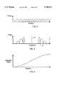
- FIG. 2illustrates a reference fringe waveform at the input of a detector shown in the apparatus of FIG. 1.
- FIG. 3illustrates the Fourier Transform of the waveform shown in FIG. 2.
- FIG. 4is a graph illustrating the advancement of phase as a function of time or sample number derived from the inverse Fourier Transform of the waveform shown in FIG. 3.
- FIG. 5is a graph illustrating the pairing of points in the graph of FIG. 4 with corresponding points in a measurement fringe waveform.
- FIG. 6is a graph illustrating the spatial domain and the frequency domain characteristics of gratings as the wavelength of a coherent light source, shown in FIG. 1, is varied over a predetermined wavelength range.
- FIGS. 1-6 of the drawingsin which like numerals refer to like features of the invention.
- apparatus 10 of the present inventiongenerally comprises control system 12, data acquisition (DAQ) circuit 14, detectors 16 and 18, laser controller 20, and coherent light source or tunable laser 22.
- DAQdata acquisition
- Control system 12performs several functions including receiving and analyzing digital data outputted by DAQ circuit 14 and outputting control signals to laser controller 20. Control system 12 outputs control signals over data bus 23 for input to laser controller 20.
- Control system 12may be implemented by a microprocessor or computer having a random access memory (RAM).
- the RAMshould be large enough to perform signal processing algorithms such as Fourier Transform analysis.
- Control system 12may be implemented by any one of the many commercially available personal computers such as the Power Macintosh 8100 manufactured by Apple Computer Inc. of Cupertino, Calif. It is highly preferable that the RAM have a size of at least 40 megabytes.
- the functions of control system 12are implemented by a software program that provides built-in hardware interfaces, displays and signal processing algorithms.
- the software programis configured with a programming language such as LabviewTM. LabViewTM provides built-in hardware interfaces, displays and signal processing algorithms that significantly reduce the total amount of programming actually required.
- Laser controller 20is a commercially available external cavity tunable laser controller and includes a piezoelectric tuning (PZT) system.
- Laser controller 20comprises circuitry to provide the drive current, temperature stabilization, picomotor tuning and drive voltage for the PZT system. Positioning the picomotor is accomplished through commands outputted by control system 12 over data bus 23. These commands are inputted into a data input port of laser controller 20.
- the PZT systemreceives an analog control voltage 24 from DAQ circuit 14 and tunes laser 22 to a specific wavelength. The actual wavelength depends upon the magnitude of the analog control voltage 24.
- the PZTtunes laser 22 over a predetermined range of wavelengths in response to a corresponding range of analog control voltages.
- Laser controller 20may be realized by a commercially available laser controller.
- laser controller 20has operational characteristics similar to the New Focus 6200 External Cavity Tunable Laser Controller, manufactured by New Focus of Santa Clara, Calif.
- the New Focus 6200 Controllerhas a GPIB port for receiving data from data bus 23.
- the New Focus 6200 Controlleralso includes a PZT system that is able to tune laser 22 over the range of 0.29 nm (nanometer). The operation of laser controller 20 will be discussed below in detail.
- laser 22is an external cavity laser which is tuned by changing the angle of a Bragg grating within the cavity and is tunable over a predetermined bandwidth.
- Laser 22may be realized by a commercially available tunable laser.
- laser 22has operational characteristics similar to the New Focus 6213 Laser.
- the New Focus 6213 Laseris tunable over its 1310 nm gain bandwidth, has a linewidth of about 100 KHz and output power of about 1 mW (milliwatt). The operation of laser 22 will be discussed below.
- Detectors 16 and 18are optical receivers. Each detector is configured to detect and convert the power or intensity of interference fringes at the detector's input into a voltage. In a preferred embodiment, each detector 16 and 18 has operational characteristics similar to the commercially available New Focus 2011 Front End Optical Receiver.
- DAQ circuit 14comprises an analog-to-digital converter (ADC) and a digital-to-analog converter (DAC).
- Data bus 26transfers data between DAQ circuit 14 and control system 12.
- the ADC circuitconverts the outputs of detectors 16 and 18 into a pair of multi-bit signals. Since high resolution is desired, it is highly preferable if each multi-bit signal comprises at least has sixteen (16) bits.
- the analog-to-digital conversionsare made at a predetermined conversion rate. Preferably, the conversion rate is between about 10 kHz and 20 kHz.
- the DAC within DAQ circuit 14receives a multi-bit signal over data bus 26 from control system 12 and converts the multi-bit signal into analog control voltage 24.
- the multi-bit signal input into the DAC circuitis comprised of at least twelve (12) bits.
- analog control voltage 24controls the tuning of the PZT system of controller 20.
- DAQ circuit 14may be realized by a commercially available data acquisition card. In a preferred embodiment, DAQ circuit 14 has operational characteristics similar to the commercially available National Instruments NB-MI-16XH-42 Data Acquisition and Control Card manufactured by National Instruments of Austin, Texas. The NB-MIO-16XH-42 can convert analog signals on two (2) channels at a 12 KHz rate to a pair of sixteen (16) bit signals.
- Coupler 30is a 2/1 fiber optic coupler that divides the light such that half the light passes through optical fiber 32 and the other half passes through optical fiber 34.
- the light in optical fiber 32passes through fiber optic coupler 36 and optical fiber 38.
- Air gap reflector 40is located in the end of optical fiber 38. In a preferred embodiment, air gap reflector 40 is formed by two (2) cleaved ends of fibers in a NorlandTM Splice Tube. Air gap reflector 40 produces a minimal reflection, typically about 7%.
- Optical fiber 42extends from the exit of reflector 40.
- Optical fiber 42has a predetermined length and is referred to herein as reference length L REF .
- Air gap reflector 44is constructed in a manner similar to air-gap reflector 40.
- Optical fiber 46extends from the exit of air-gap reflector 44. End 48 of optical fiber 46 is shattered so that no light is reflected back down optical fiber 42.
- the light reflected from air gap reflector 40passes through coupler 36.
- the light reflected from air-gap reflector 44passes through coupler 36.
- the light reflected from reflector 40interferes with the light reflected from reflector 44 and produces a fringe or interference fringe (also known as an interference fringe pattern).
- the terms fringe or interference fringeare defined as the change from high to low intensity when the interference shifts from a constructive interference to a destructive interference.
- the interference fringeis inputted into detector 16 via optical fiber 37. This interference fringe is referred to herein as a "reference interference fringe".
- Detector 16detects the intensity of the interference fringe. The intensity is the power of the resulting interference fringe.
- Detector 16converts the intensity (or power) into current which is then converted into a voltage.
- the voltageis inputted into DAQ circuit 14 which converts the voltage into a multi-bit signal via the ADC of DAQ circuit 14. As stated above, this multi-bit signal preferably comprises 16 (sixteen) bits.
- Optical fibers 38, 42 and reflectors 40, 44form a "reference cavity".
- optical fiber 52The other half of the light emanating from tunable laser 22 passes through coupler 30, optical fiber 34 and optical coupler 50.
- the light exiting optical coupler 50travels down optical fiber 52.
- the length of optical fiber 52can be any length, possibly even kilometers long. It is highly preferable that optical fiber 52 contain no reflections.
- Air gap reflector 54is located at the end of optical fiber 52 and is formed in a manner similar to air gap reflectors 40 and 44 discussed above. Air gap reflector 54 is referred to as a reference reflector.
- Optical fiber 56extends from the exit of air gap reflector 40 and is referred to as a "buffer section".
- Optical fiber 56has a predetermined length referred to as buffer length L B . It is highly preferable that optical fiber 56 (or buffer section) contain no reflections.
- Optical fiber section 58is a "sensing section" and has a plurality of Bragg gratings 60 written thereon. In a preferred embodiment, optical fiber section 58 has
- the light that is not reflected by the reference reflector 54travels through optical fiber 56 (or buffer section) and, if it has the proper wavelength, is reflected by one or more of the Bragg gratings 60.
- the end of optical fiber 58(the sensing section) is preferably shattered so that no light is reflected.
- the light reflected from Bragg gratings 60 and the light reflected from reference air gap reflector 54return through optical fiber 52 and passes through optical coupler 50.
- the output of optical coupler 50is coupled to optical fiber 62 which passes the light into detector 18.
- the light reflected from Bragg gratings 60interferes with the light reflected from reference air gap reflector 54 thereby producing an interference fringe. This fringe is referred to herein as the "measurement interference fringe".
- the total intensity of this measurement interference fringedepends upon the phase amplitude of the lightwaves reflected from reflector 54 and Bragg gratings 60. If the wavelength of optical fiber 58 changes due to strain, the amplitude and phase of the lightwave reflected from gratings 60 will also change thereby resulting variations in the power of the interference fringe at the input to detector 18.
- Detector 18converts the power (or intensity) of this interference fringe into a voltage level.
- the ADC of DAQ circuit 14converts this voltage into a multi-bit signal. As discussed above, this multi-bit signal preferably comprises 16 (sixteen) bits.
- the multi-bit signalis inputted into control system 12 through data bus 26.
- the light detected by detector 16is converted into a multi-bit signal by DAQ circuit 14.
- This multi-bit signalis used by control system 12 to accurately measure the change in the wavelength of tunable laser 22 as it is tuned by the PZT of laser controller 20.
- the change in wavelength of tunable laser 22is monotonic.
- measurement of the change in wavelengthmay be achieved by counting the fringes detected by detector 16 as the wavelength of tunable laser 22 is swept.
- the relationship between the wavelength of the light outputted by tunable laser 22 and the fringe sizeis expressed by the formula:
- ⁇is the wavelength of the output of tunable laser 22
- L REFis the length of optical fiber 42
- nis the index of refraction of the optical fiber 42.
- nis about 1.46.
- laser 22can be implemented by any coherent light source that has wavelength tuning capability.
- the first step of the method of the present inventioncomprises setting the wavelength of tunable laser 22 to the beginning of the predetermined sweep range.
- control system 12outputs a command over data bus 23 which is inputted into the data input (the GPIB port) of laser controller 20.
- the commandrepresents a predetermined initial position of the picomotor of laser controller 20.
- the next stepentails sweeping tunable laser 22 through a wavelength range that is determined by the tuning range of the PZT.
- the PZT of laser controller 20has a tuning range of about 0.29 nm as discussed above. It is highly preferred that the PZT be swept over a range that is less than the maximum tuning range of the PZT in order to avoid distortion. Thus, the PZT is swept over a range of 0.23 nm.
- control system 12outputs a series of multi-bit signals over data bus 26 to DAQ circuit 14. These multi-bit signals are digital representations of analog voltages within a predetermined range. The voltage range depends upon the operational characteristics of laser controller 20.
- the multi-bit signalsare inputted into the DAC of DAQ circuit 14 which converts the multi-bit signals into analog voltages within the predetermined range.
- the analog voltagesare inputted into the PZT voltage input of laser controller 20.
- FIG. 2shows an example of a reference fringe at the input of detector 16 which results from one (1) wavelength sweep by the PZT.
- the horizontal axis in FIG. 2is typically in the time domain. However, since the ADC of DAQ circuit 14 is sampling at even increments, the horizontal axis in FIG. 2 represents sample number n.
- the vertical axis in FIG. 2represents power at the input to detector 16.
- the intensities of the reference and measurement interference fringesare converted to analog voltages as discussed above.
- the analog voltagesare inputted into the ADC of DAQ circuit 14 which converts the analog voltages into respective digital representations of the intensities of the reference interference fringe and the measurement interference fringe. These digital representations are transferred to control system 12 via data bus 26. Control system 12 creates arrays of these digital representations and the corresponding sample times or sample numbers, i.e. each digital representation has a corresponding sample number.
- control system 12At the end of each sweep, control system 12 outputs a command over data bus 23 that is inputted into laser controller 20. This command advances the picomotor by 0.23 nm. The steps described above are then repeated. Control system 12 outputs another series of multi-bit signals for input into the DAC of DAQ circuit 14. In response, the DAQ circuit 14 outputs the same predetermined range of voltages discussed above (e.g. -3 v to +3 v) for input into the PZT input of laser controller 20. Tunable laser 22 is again swept over a 0.23 nm. The total number of sweeps determines the number of reference and measurement fringes that will be measured. The number of sweeps depends upon the desired bandwidth coverage.
- laser 22is controlled to output optical radiation over a plurality of contiguous wavelength ranges or bands. For example, if it is necessary to vary the wavelength of tunable laser 22 by 2.3 nm, and the tuning range of the PZT is 0.23 nm, then ten (10) contiguous sweeps are needed. As a result, there will be ten (10) sets of reference interference fringe data and ten (10) sets of measurement interference fringe data.
- control system 12performs a Fourier Transform of the reference interference fringe waveform shown in FIG. 2. This is actually achieved by performing a Discrete Fourier Transform (DFT) on the array that consists of the digital representations of the reference interference fringe and the sample numbers as discussed above.
- DFTDiscrete Fourier Transform
- the DFT datais processed such that the frequency responses at OHz and all frequencies above the Nyquist frequency are filtered out, i.e. these responses are set to zero. This can be accomplished by a software routine executed by control system 12.
- the Nyquist frequencyis one-half the wavenumber sample-rate.
- FIG. 3shows the Fourier Transform of the reference interference fringe shown in FIG. 2.
- Numeral 63refers to the Nyquist frequency.
- Numeral 65refers to the negative frequencies (or the frequencies above the Nyquist frequency).
- control system 12After the frequency response of the specified frequencies are set to zero, control system 12 performs an inverse Fourier Transform on the array resulting from the DFT discussed above. This can be accomplished with a suitable software routine executed by control system 12.
- the inverse Fourier Transform on the aforementioned arrayproduces a complex array having real and complex parts.
- the real partis comprised of the original reference interference fringe minus the d.c. offset.
- the imaginary partis the quadrature complement to the original reference interference fringe minus the d.c. offset.
- the complex arrayis then converted to polar representation and the phase is unwrapped. Since phase is an angle, traversing 360° results in arrival at the starting point, 0°. Thus, such a complete traversal is referred to as "wrapping" around the phase circle.
- phaseadjacent samples are analyzed to determine if the phase is 0° or 360°. This results in phase values that are larger than 360° and which form relatively smooth curves. Similar to the DFT and the inverse thereof described above, conversion to polar representation and phase "unwrapping" may be implemented by a software routine executed by control system 12.
- the conversion to polar representation and phase unwrappingyields a graph of the advancement of phase as a function of time or sample number.
- This phase advancementresults from the PZT sweeping through the wavelength sweep range. Every 2 ⁇ of phase change corresponds to a wavelength change of ⁇ fringe .
- the precise wavelength change of reference optical fiber 42, with respect to the starting wavelength of each sweepis known at every sample point.
- X-axis 64denotes measurement locations in the wavenumber domain of measurement interference fringe 68.
- the next step of the method of the present inventioncomprises pairing or matching each point in measurement interference fringe array with a point in the phase advancement graph shown (FIG. 4).
- the measurement fringe arraycomprises sampled values of the measurement interference fringe produced by the ADC of DAQ circuit 14 and stored in control system 12. Such a point-to-point matching results in a measure of each measurement fringe as a function of wavelength change.
- This pairing or matching stepproduces an array of calibration data for use in determining the actual strain on the Bragg gratings.
- a wavelength change in optical fiber 42 (the reference optical fiber) caused by the PZTis matched to a point in the measurement fringe. Therefore, the actual wavelength change produced by the PZT is taken into consideration when determining the wavelength change in optical fiber 52 (the sensing section) due to strain.
- the next stepentails performing a Fast Fourier Transform (FFT) on measurement fringe 68 (FIG. 5).
- FFTFast Fourier Transform
- measurement points 66 of X-axis 64are not evenly spaced.
- Measurement interference fringe 68was sampled at even increments of time.
- the measurement points 66were not sampled at even increment of wavenumber. Therefore, in a most preferred embodiment, the measurement points of measurement interference fringe 68 are linearized prior to performing the FFT.
- the first step in linearizing the measurement pointsis selecting a sample spacing and length.
- the sample spacingis chosen to be about the average spacing of uneven measurement points 66 of X-axis 64. As shown in FIG.
- the selected spacingis denoted by tick marks 70 on upper X-axis 72.
- the values of the measurement interference fringe 68are determined at each sample position (or tick mark) on upper X-axis 72. This is accomplished by identifying the original measurement or sample point 66 (on X-axis 64) lying to the left and right of each tick mark 70 and linearly interpolating the value of the measurement interference fringe 68 at the tick mark. Then, an FFT is performed on the interpolated values of the measurement interference fringe. Performing the FFT transfers the measurement fringe from the wavenumber domain to the spatial domain. As described above, the FFT of the linearized measurement fringe array is effected by control system 12 via execution of the appropriate software routine. FIG.
- FIG. 6illustrates the transformation of three (3) sets of measurement interference fringe arrays, produced by sweeping three (3) contiguous wavelength ranges, from the wavenumber domain into the spatial domain.
- the X-axis associated with each waveform 74, 76 and 78is distance along optical fiber 52 with respect to reflector 54.
- Waveforms 74, 76, and 78represent the FFT of the aforementioned interference fringes.
- the point-to-point matching, linearization of sample points and the FFTis effected by control system 12 via execution of the appropriate software routine.
- the next stepentails summing the corresponding amplitudes of each of the waveforms 74, 76 and 78 to produce waveform 80.
- Control system 12via the appropriate software routine, performs the aforementioned summing function.
- Waveform 80allows location of each grating in space without respect to its wavelength. Waveform 80 is used only to identify the grating location and width for use in the next step of the method. Each grating location is with respect to reference reflector 54 (FIG. 1).
- the next step of the method of the present inventionentails extracting values from waveforms 74, 76 and 78, that are associated with a particular grating.
- the extracted valuesare Fourier Transformed by control system 12, back into the wavenumber domain. This transformation results in spectrum graphs 92, 94, 96.
- Each spectrum graph 92, 94, and 96represents the spectrum of the selected Bragg grating over the three (3) contiguous wavelength ranges that are swept via laser controller 20 and tunable laser 22.
- Spectrum graphs 92, 94, and 96may be concatenated to form composite spectrum graph 98 wherein portions 100, 102, 104 correspond to graphs 92, 94 and 96, respectively.
- the next stepis to analyze the shift in the spectrum (graph 98) of the selected grating.
- the strain on the grating at each wavelength of optical radiationis determined by determining the difference between the current wavelength and an earlier, zero-strain wavelength measurement.
- correlation waveforms 106, 108 and 110result from interference of light reflected from two (2) Bragg gratings.
- Waveform 112is the summation of correlation waveforms 106, 108 and 110.
Landscapes
- Physics & Mathematics (AREA)
- General Physics & Mathematics (AREA)
- Length Measuring Devices By Optical Means (AREA)
Abstract
Description
This application claims the benefit of co-pending U.S. provisional application Ser. No. 60/012,356, filed Feb. 27, 1996.
The invention described herein was made by an employee of the United States Government and may be used by or for the Government for governmental purposes without the payment of any royalties thereon or therefor.
1. Field of the Invention
The present invention is generally related to an apparatus and method for measuring the strain of Bragg gratings written into an optical fiber.
2. Problem to be Solved
It is often desirable to measure optical fibers for strains that occur when the optical fibers are stressed. Such stress can occur if the optical fiber is subject to physical forces that stretch, contort or contract the optical fiber. Stress to the optical fibers can also occur as a result of variations in temperature of the environment within which the optical fiber is located. Such physical forces and temperature variation are typically found in aerospace environments such as aircraft or spacecraft.
Fiber Bragg Gratings have been used to sense strain in optical fibers. Fiber Bragg Gratings comprise a portion of the optical fiber where the index of refraction has been changed. The gratings are written on a section of the optical fiber which is then bonded to longer lead-in, lead-out optical fibers. Coherent light of a specific wavelength is transmitted down the core of the optical fiber. The coherent light reflects off the Bragg Gratings of the same wavelength and passes back up the fiber. As the grating spacing changes in response to strain, the index of refraction of the grating changes thereby altering the period of the modulation of the index of refraction. Multiple Fiber Bragg Grating configurations can also be used for measuring strain. In such a configuration, each Bragg grating has a unique central frequency (and no overlap of the frequency response). Thus, multiplexed signals can be transmitted by the optical fiber and discriminated by the Fiber Bragg Gratings. Conventional systems and methods of interrogating Bragg gratings involve the determination of the center frequency of the grating. These methods typically discard the information available from the entire spectral response of the Bragg grating. Thus, these conventional systems and methods measure only the point strain in an optical fiber. What is needed is a system and method for measuring the strain at each point in the Bragg grating.
It is therefore an object of the present invention to provide a new and improved apparatus and method for measuring the modulation of the index of refraction of a Bragg grating.
It is another object of the present invention to provide a new and improved apparatus and method for measuring the strain at every point along a Bragg grating.
It is a further object of the present invention to provide a new and improved apparatus and method for measuring the strain at every point along a Bragg grating with a relatively high degree of accuracy.
It is yet another object of the present invention to provide a new and improved apparatus and method for measuring the strain at every point along a Bragg grating that may be implemented cost effectively.
Still other objects and advantages of the present invention will in part be obvious and will in part be apparent from the specification.
The above and other objects and advantages, which will be apparent to one of skill in the art, are achieved in the present invention which is directed to an apparatus and method for measuring the complete spectral response of Fiber Bragg Gratings so that the strain at each point in the grating can be measured. In accordance with the present invention, optical radiation is transmitted over a plurality of contiguous predetermined wavelength ranges into a reference optical fiber and an optical fiber under test to produce reference and measurement interference fringes. The optical fiber under test has a plurality of gratings written therein. The reference and measurement interference fringes are detected and sampled such that each sampled value of the reference and measurement fringes is associated with a corresponding sample number. The next step entails determining for each sample number the wavelength change of the reference optical fiber due to the wavelength of the optical radiation. Each wavelength change determined for each sample number is then matched with a corresponding sampled value of each measurement fringe. Each sampled measurement fringe is transformed into a spatial domain waveform such that each spatial domain waveform corresponds to one of the contiguous predetermined wavelength ranges. The spatial domain waveforms are then summed to form a summation spatial domain waveform. The summation spatial domain waveform is then analyzed to determine the location of each grating with respect to a reflector of the optical fiber under test. The next step entails determining from each spatial waveform a portion of the spatial domain waveform that corresponds to a particular grating. Each of these determined portions of the spatial domain waveforms are transformed into a corresponding frequency spectrum representation. The strain on the grating at each wavelength of optical radiation is then determined by determining the difference between the current wavelength and an earlier, zero-strain wavelength measurement.
The features of the invention are believed to be novel and the elements characteristic of the invention are set forth with particularity in the appended claims. The figures are for illustration purposes only and are not drawn to scale. The invention itself, however, both as to organization and method of operation, may best be understood by reference to the detailed description which follows taken in conjunction with the accompanying drawings in which:
FIG. 1 is a block diagram of the strain measurement apparatus of the present invention.
FIG. 2 illustrates a reference fringe waveform at the input of a detector shown in the apparatus of FIG. 1.
FIG. 3 illustrates the Fourier Transform of the waveform shown in FIG. 2.
FIG. 4 is a graph illustrating the advancement of phase as a function of time or sample number derived from the inverse Fourier Transform of the waveform shown in FIG. 3.
FIG. 5 is a graph illustrating the pairing of points in the graph of FIG. 4 with corresponding points in a measurement fringe waveform.
FIG. 6 is a graph illustrating the spatial domain and the frequency domain characteristics of gratings as the wavelength of a coherent light source, shown in FIG. 1, is varied over a predetermined wavelength range.
In describing the preferred embodiments of the present invention, reference will be made herein to FIGS. 1-6 of the drawings in which like numerals refer to like features of the invention.
As discussed above, conventional systems and methods of interrogating Bragg gratings involve the determination of the center frequency of the grating. These conventional methods do not utilize the information available from the entire spectral response of the Bragg grating. Contrary to these conventional methods, the apparatus and method of the present invention measures the entire spectral response of the in-fiber Bragg grating. By measuring the complete spectral response of the Bragg grating, the strain at each point in the grating can be measured. Therefore, longer (and fewer) gratings could be used to cover the same fiber length.
Referring to FIG. 1,apparatus 10 of the present invention generally comprisescontrol system 12, data acquisition (DAQ)circuit 14,detectors laser controller 20, and coherent light source ortunable laser 22.
In a preferred embodiment,laser 22 is an external cavity laser which is tuned by changing the angle of a Bragg grating within the cavity and is tunable over a predetermined bandwidth.Laser 22 may be realized by a commercially available tunable laser. In a most preferred embodiment,laser 22 has operational characteristics similar to the New Focus 6213 Laser. The New Focus 6213 Laser is tunable over its 1310 nm gain bandwidth, has a linewidth of about 100 KHz and output power of about 1 mW (milliwatt). The operation oflaser 22 will be discussed below.
Referring to FIG. 1,laser 22 transmits optical radiation or lightwaves throughoptical fiber 28 and intocoupler 30.Coupler 30 is a 2/1 fiber optic coupler that divides the light such that half the light passes throughoptical fiber 32 and the other half passes throughoptical fiber 34. The light inoptical fiber 32 passes throughfiber optic coupler 36 andoptical fiber 38.Air gap reflector 40 is located in the end ofoptical fiber 38. In a preferred embodiment,air gap reflector 40 is formed by two (2) cleaved ends of fibers in a Norland™ Splice Tube.Air gap reflector 40 produces a minimal reflection, typically about 7%.Optical fiber 42 extends from the exit ofreflector 40.Optical fiber 42 has a predetermined length and is referred to herein as reference length LREF. The transmitted light continues downoptical fiber 42 until it encounters air-gap reflector 44 located at the end ofoptical fiber 42.Air gap reflector 44 is constructed in a manner similar to air-gap reflector 40.Optical fiber 46 extends from the exit of air-gap reflector 44.End 48 ofoptical fiber 46 is shattered so that no light is reflected back downoptical fiber 42. The light reflected fromair gap reflector 40 passes throughcoupler 36. Similarly, the light reflected from air-gap reflector 44 passes throughcoupler 36. The light reflected fromreflector 40 interferes with the light reflected fromreflector 44 and produces a fringe or interference fringe (also known as an interference fringe pattern). As used herein, the terms fringe or interference fringe are defined as the change from high to low intensity when the interference shifts from a constructive interference to a destructive interference. The interference fringe is inputted intodetector 16 viaoptical fiber 37. This interference fringe is referred to herein as a "reference interference fringe".Detector 16 detects the intensity of the interference fringe. The intensity is the power of the resulting interference fringe.Detector 16 converts the intensity (or power) into current which is then converted into a voltage. The voltage is inputted intoDAQ circuit 14 which converts the voltage into a multi-bit signal via the ADC ofDAQ circuit 14. As stated above, this multi-bit signal preferably comprises 16 (sixteen) bits.Optical fibers reflectors
The other half of the light emanating fromtunable laser 22 passes throughcoupler 30,optical fiber 34 andoptical coupler 50. The light exitingoptical coupler 50 travels downoptical fiber 52. The length ofoptical fiber 52 can be any length, possibly even kilometers long. It is highly preferable thatoptical fiber 52 contain no reflections.Air gap reflector 54 is located at the end ofoptical fiber 52 and is formed in a manner similar toair gap reflectors Air gap reflector 54 is referred to as a reference reflector.Optical fiber 56 extends from the exit ofair gap reflector 40 and is referred to as a "buffer section".Optical fiber 56 has a predetermined length referred to as buffer length LB. It is highly preferable that optical fiber 56 (or buffer section) contain no reflections.Optical fiber section 58 is a "sensing section" and has a plurality ofBragg gratings 60 written thereon. In a preferred embodiment,optical fiber section 58 has a length LS that is substantially equal to LB.
The light that is not reflected by thereference reflector 54 travels through optical fiber 56 (or buffer section) and, if it has the proper wavelength, is reflected by one or more of the Bragg gratings 60. The end of optical fiber 58 (the sensing section) is preferably shattered so that no light is reflected. The light reflected fromBragg gratings 60 and the light reflected from referenceair gap reflector 54 return throughoptical fiber 52 and passes throughoptical coupler 50. The output ofoptical coupler 50 is coupled tooptical fiber 62 which passes the light intodetector 18. The light reflected fromBragg gratings 60 interferes with the light reflected from referenceair gap reflector 54 thereby producing an interference fringe. This fringe is referred to herein as the "measurement interference fringe". The total intensity of this measurement interference fringe depends upon the phase amplitude of the lightwaves reflected fromreflector 54 and Bragg gratings 60. If the wavelength ofoptical fiber 58 changes due to strain, the amplitude and phase of the lightwave reflected fromgratings 60 will also change thereby resulting variations in the power of the interference fringe at the input todetector 18.
As described above, the light detected bydetector 16 is converted into a multi-bit signal byDAQ circuit 14. This multi-bit signal is used bycontrol system 12 to accurately measure the change in the wavelength oftunable laser 22 as it is tuned by the PZT oflaser controller 20. The change in wavelength oftunable laser 22 is monotonic. Thus, measurement of the change in wavelength may be achieved by counting the fringes detected bydetector 16 as the wavelength oftunable laser 22 is swept. The relationship between the wavelength of the light outputted bytunable laser 22 and the fringe size is expressed by the formula:
Δλ.sub.fringe =λ.sup.2 /2nL.sub.ref
wherein λ is the wavelength of the output oftunable laser 22, LREF is the length ofoptical fiber 42, and n is the index of refraction of theoptical fiber 42. Typically, n is about 1.46.
The method of the present invention will now be discussed in detail. For purposes of the ensuing discussion, the components of the apparatus of the present invention will have the operational characteristics of the commercially available components discussed above. However, it is to be understood that other components having similar operational characteristics may be used to implement the method of the present invention. For example,laser 22 can be implemented by any coherent light source that has wavelength tuning capability.
The first step of the method of the present invention comprises setting the wavelength oftunable laser 22 to the beginning of the predetermined sweep range. To effects setting the wavelength oftunable laser 22,control system 12 outputs a command overdata bus 23 which is inputted into the data input (the GPIB port) oflaser controller 20. The command represents a predetermined initial position of the picomotor oflaser controller 20.
The next step entails sweepingtunable laser 22 through a wavelength range that is determined by the tuning range of the PZT. The PZT oflaser controller 20 has a tuning range of about 0.29 nm as discussed above. It is highly preferred that the PZT be swept over a range that is less than the maximum tuning range of the PZT in order to avoid distortion. Thus, the PZT is swept over a range of 0.23 nm. In order to accomplish this,control system 12 outputs a series of multi-bit signals overdata bus 26 toDAQ circuit 14. These multi-bit signals are digital representations of analog voltages within a predetermined range. The voltage range depends upon the operational characteristics oflaser controller 20. For example, iflaser controller 20 has operational characteristics of the New Focus 6200 Controller discussed above, then a voltage range of -3 volts to +3 volts would be suitable to effect a sweep range of 0.23 nm. The multi-bit signals are inputted into the DAC ofDAQ circuit 14 which converts the multi-bit signals into analog voltages within the predetermined range. The analog voltages are inputted into the PZT voltage input oflaser controller 20.
As the wavelength oftunable laser 22 is swept over the range based on the PZT tuning range, the intensities of the reference interference fringes emanating from the reference cavity (described above) and the measurement interference fringes emanating from the sensing section (described above) are detected bydetectors detector 16 which results from one (1) wavelength sweep by the PZT. The horizontal axis in FIG. 2 is typically in the time domain. However, since the ADC ofDAQ circuit 14 is sampling at even increments, the horizontal axis in FIG. 2 represents sample number n. The vertical axis in FIG. 2 represents power at the input todetector 16. The intensities of the reference and measurement interference fringes are converted to analog voltages as discussed above. The analog voltages are inputted into the ADC ofDAQ circuit 14 which converts the analog voltages into respective digital representations of the intensities of the reference interference fringe and the measurement interference fringe. These digital representations are transferred to controlsystem 12 viadata bus 26.Control system 12 creates arrays of these digital representations and the corresponding sample times or sample numbers, i.e. each digital representation has a corresponding sample number.
At the end of each sweep,control system 12 outputs a command overdata bus 23 that is inputted intolaser controller 20. This command advances the picomotor by 0.23 nm. The steps described above are then repeated.Control system 12 outputs another series of multi-bit signals for input into the DAC ofDAQ circuit 14. In response, theDAQ circuit 14 outputs the same predetermined range of voltages discussed above (e.g. -3 v to +3 v) for input into the PZT input oflaser controller 20.Tunable laser 22 is again swept over a 0.23 nm. The total number of sweeps determines the number of reference and measurement fringes that will be measured. The number of sweeps depends upon the desired bandwidth coverage. Thus,laser 22 is controlled to output optical radiation over a plurality of contiguous wavelength ranges or bands. For example, if it is necessary to vary the wavelength oftunable laser 22 by 2.3 nm, and the tuning range of the PZT is 0.23 nm, then ten (10) contiguous sweeps are needed. As a result, there will be ten (10) sets of reference interference fringe data and ten (10) sets of measurement interference fringe data.
As shown in FIG. 2, frequency is not constant, as would be expected from a linear wavelength sweep. It is highly preferable that the non-linearity be removed from the measurement interference fringe. If the non-linearity is not removed, the Fourier Transform into distance space from wavenumber space may be corrupted, and reflections may be "smeared out" over the length of the fiber. In order to remove the non-linearity,control system 12 performs a Fourier Transform of the reference interference fringe waveform shown in FIG. 2. This is actually achieved by performing a Discrete Fourier Transform (DFT) on the array that consists of the digital representations of the reference interference fringe and the sample numbers as discussed above. The DFT produces another array of data that will be discussed below. Next, the DFT data is processed such that the frequency responses at OHz and all frequencies above the Nyquist frequency are filtered out, i.e. these responses are set to zero. This can be accomplished by a software routine executed bycontrol system 12. After linearization, the Nyquist frequency is one-half the wavenumber sample-rate. FIG. 3 shows the Fourier Transform of the reference interference fringe shown in FIG. 2.Numeral 63 refers to the Nyquist frequency.Numeral 65 refers to the negative frequencies (or the frequencies above the Nyquist frequency).
After the frequency response of the specified frequencies are set to zero,control system 12 performs an inverse Fourier Transform on the array resulting from the DFT discussed above. This can be accomplished with a suitable software routine executed bycontrol system 12. The inverse Fourier Transform on the aforementioned array produces a complex array having real and complex parts. The real part is comprised of the original reference interference fringe minus the d.c. offset. The imaginary part is the quadrature complement to the original reference interference fringe minus the d.c. offset. The complex array is then converted to polar representation and the phase is unwrapped. Since phase is an angle, traversing 360° results in arrival at the starting point, 0°. Thus, such a complete traversal is referred to as "wrapping" around the phase circle. To "unwrap" the phase, adjacent samples are analyzed to determine if the phase is 0° or 360°. This results in phase values that are larger than 360° and which form relatively smooth curves. Similar to the DFT and the inverse thereof described above, conversion to polar representation and phase "unwrapping" may be implemented by a software routine executed bycontrol system 12.
Referring to FIG. 4, the conversion to polar representation and phase unwrapping yields a graph of the advancement of phase as a function of time or sample number. This phase advancement results from the PZT sweeping through the wavelength sweep range. Every 2π of phase change corresponds to a wavelength change of Δλfringe. As a result, the precise wavelength change of referenceoptical fiber 42, with respect to the starting wavelength of each sweep, is known at every sample point.
Referring to FIG. 5,X-axis 64 denotes measurement locations in the wavenumber domain ofmeasurement interference fringe 68. The next step of the method of the present invention comprises pairing or matching each point in measurement interference fringe array with a point in the phase advancement graph shown (FIG. 4). The measurement fringe array comprises sampled values of the measurement interference fringe produced by the ADC ofDAQ circuit 14 and stored incontrol system 12. Such a point-to-point matching results in a measure of each measurement fringe as a function of wavelength change. This pairing or matching step produces an array of calibration data for use in determining the actual strain on the Bragg gratings. Thus, for a particular sample time, a wavelength change in optical fiber 42 (the reference optical fiber) caused by the PZT is matched to a point in the measurement fringe. Therefore, the actual wavelength change produced by the PZT is taken into consideration when determining the wavelength change in optical fiber 52 (the sensing section) due to strain.
The next step entails performing a Fast Fourier Transform (FFT) on measurement fringe 68 (FIG. 5). However, as shown in FIG. 5, measurement points 66 ofX-axis 64 are not evenly spaced.Measurement interference fringe 68 was sampled at even increments of time. However, since the PZT is not linear, as described above, measurement points 66 were not sampled at even increment of wavenumber. Therefore, in a most preferred embodiment, the measurement points ofmeasurement interference fringe 68 are linearized prior to performing the FFT. The first step in linearizing the measurement points is selecting a sample spacing and length. Preferably, the sample spacing is chosen to be about the average spacing of uneven measurement points 66 ofX-axis 64. As shown in FIG. 5, the selected spacing is denoted bytick marks 70 onupper X-axis 72. Next, the values of themeasurement interference fringe 68 are determined at each sample position (or tick mark) onupper X-axis 72. This is accomplished by identifying the original measurement or sample point 66 (on X-axis 64) lying to the left and right of eachtick mark 70 and linearly interpolating the value of themeasurement interference fringe 68 at the tick mark. Then, an FFT is performed on the interpolated values of the measurement interference fringe. Performing the FFT transfers the measurement fringe from the wavenumber domain to the spatial domain. As described above, the FFT of the linearized measurement fringe array is effected bycontrol system 12 via execution of the appropriate software routine. FIG. 6 illustrates the transformation of three (3) sets of measurement interference fringe arrays, produced by sweeping three (3) contiguous wavelength ranges, from the wavenumber domain into the spatial domain. The X-axis associated with eachwaveform optical fiber 52 with respect toreflector 54.Waveforms control system 12 via execution of the appropriate software routine.
The next step entails summing the corresponding amplitudes of each of thewaveforms waveform 80.Control system 12, via the appropriate software routine, performs the aforementioned summing function.Waveform 80 allows location of each grating in space without respect to its wavelength.Waveform 80 is used only to identify the grating location and width for use in the next step of the method. Each grating location is with respect to reference reflector 54 (FIG. 1).
The next step of the method of the present invention entails extracting values fromwaveforms vertical lines values waveforms control system 12, back into the wavenumber domain. This transformation results inspectrum graphs spectrum graph laser controller 20 andtunable laser 22.Spectrum graphs composite spectrum graph 98 whereinportions graphs
The next step is to analyze the shift in the spectrum (graph 98) of the selected grating. The strain on the grating at each wavelength of optical radiation is determined by determining the difference between the current wavelength and an earlier, zero-strain wavelength measurement.
Although the discussion above pertains to a selected grating, it is to be understood that the steps above are implemented for all gratings. Thus, the strain at each grating in each Bragg grating 60 can be measured independently.
Referring again to FIG. 6,correlation waveforms Waveform 112 is the summation ofcorrelation waveforms Bragg gratings 60. Such correlation effects occur between zero and Ls. Thus, the use of optical fiber 56 (buffer) is highly preferred.
While the present invention has been particularly described, in conjunction with a specific preferred embodiment, it is evident that many alternatives, modifications and variations will be apparent to those skilled in the art in light of the foregoing description. It is therefore contemplated that the appended claims will embrace any such alternatives, modifications and variations as falling within the true scope and spirit of the present invention.
Claims (30)
1. A method for measuring strain of gratings written in an optical fiber comprising the steps of:
a) providing a reference optical fiber network having a reference optical fiber;
b) transmitting optical radiation over a plurality of contiguous predetermined wavelength ranges into the reference optical fiber network and an optical fiber network under test, the optical fiber network under test including a reflector and a sensing optical fiber having a plurality of gratings written thereon, the transmission of optical radiation over each wavelength range into the reference optical fiber network and the optical fiber network under test producing a plurality of reference interference fringes and measurement interference fringes, respectively;
c) detecting the reference and measurement interference fringes;
d) sampling the detected reference and measurement interference fringes such that each sampled value of the reference and measurement interference fringes is associated with a corresponding sample number;
e) determining for each sample number the wavelength change of the reference optical fiber due to the wavelength of the optical radiation;
f) matching each wavelength change determined in step (e) with a corresponding sampled value of each measurement interference fringe;
g) transforming each sampled measurement interference fringe into a spatial domain waveform such that each spatial domain waveform corresponds to one of the contiguous predetermined wavelength ranges;
h) summing the spatial domain waveforms to form a summation spatial domain waveform;
i) determining from the summation spatial domain waveform the location of each grating with respect to the reflector of the optical fiber network under test;
j) determining from each spatial domain waveform of transforming step (g) a portion of the spatial domain waveform corresponding to a particular grating;
k) transforming each portion determined in step (j) into a corresponding frequency spectrum representation; and
l) determining the strain on the grating at each wavelength of optical radiation by determining the difference between the current wavelength and an earlier, zero-strain wavelength measurement.
2. The method according to claim 1 further comprising the step (m) of repeating steps (j)-(l) for every grating written on the sensing optical fiber.
3. The method according to claim 1 wherein step (k) further comprises concatenating each frequency spectrum representation to form a composite frequency spectrum representation.
4. The method according to claim 1 wherein detecting step (c) comprises the steps of:
detecting the power of the reference and measurement interference fringes; and
converting the power of the reference and measurement interference fringes to analog voltage waveforms.
5. The method according to claim 1 wherein sampling step (d) comprises the step of:
digitizing the sample values; and
forming arrays comprising the digitized sample values of the reference and measurement interference fringes and sample numbers associated with the digitized sample values wherein each digitized sample value has a corresponding sample number indicating a point in time when the digitized sampled value was produced.
6. The method according to claim 5 further comprising the steps of:
forming data arrays comprising the digitized samples and the corresponding sample numbers; and
storing the data arrays in a storage medium.
7. The method according to claim 1 wherein the determining step (e) comprises producing a discrete Fourier Transform based on the samples and sample numbers associated with the reference interference fringe.
8. The method according to claim 7 further comprising the step of filtering the produced discrete Fourier Transform such that the responses at 0 Hz and all frequencies above a predetermined Nyquist frequency are substantially zero.
9. The method according to claim 8 further comprising the step of producing an inverse Fourier Transform based on the filtered discrete Fourier Transform to produce a complex array comprising a real part and an imaginary part, the real part being the reference interference fringe without a DC offset, the imaginary part being the quadrature complement to the real part.
10. The method according to claim 9 further comprising the step of converting the complex array to polar representation.
11. The method according to claim 10 further comprising the step of unwrapping the phase of the polar representation to produce phase values for each sample number.
12. The method according to claim 11 further comprising the step of determining the change in wavelength of the reference optical fiber for each phase value.
13. The method according to claim 1 wherein transforming step (g) comprises the step of producing a discrete Fourier Transform based on the samples and sample numbers associated with the measurement interference fringes to produce the spatial domain waveforms.
14. The method according to claim 13 wherein each measurement interference fringe is linearized prior to producing the discrete Fourier Transform.
15. The method according to claim 1 wherein each contiguous wavelength range has a bandwidth that is less than 0.29 nm.
16. An apparatus for measuring strain of gratings written in an optical fiber comprising:
a reference optical fiber network having a reference optical fiber;
a coherent light source for transmitting optical radiation over a plurality of contiguous predetermined wavelength ranges into the reference optical fiber network and an optical fiber network under test, the optical fiber network under test including a reflector and a sensing optical fiber having a plurality of gratings written thereon, the transmission of optical radiation over each wavelength range into the reference optical fiber network and the optical fiber network under test producing a plurality of reference interference fringes and measurement interference fringes, respectively;
a detector for detecting the reference and measurement interference fringes;
a circuit for sampling the detected reference and measurement interference fringes such that each sampled value of the reference and measurement interference fringes is associated with a corresponding sample number; and
a control system for (l) determining for each sample number the wavelength change of the reference optical fiber due to the wavelength of optical radiation, (ii) matching each wavelength change with a corresponding sampled value of each measurement interference fringe, (iii) transforming each sampled measurement interference fringe into a spatial domain waveform such that each spatial domain waveform corresponds to one of the contiguous predetermined wavelength ranges, (iv) summing the spatial domain waveforms to form a summation spatial domain waveform, (v) determining from the summation spatial domain waveform the location of each grating with respect to the reflector of the optical fiber network under test, (vi) determining from each spatial domain waveform the portion of the spatial domain waveform corresponding to a particular grating, (vii) transforming each portion into a frequency spectrum representation, and (viii) determining the strain on the grating at each wavelength of optical radiation by determining the difference between the current wavelength and an earlier, zero-strain wavelength measurement.
17. The apparatus according to claim 16 wherein the control system performs functions (l)-(viii) on each grating written into the sensing optical fiber.
18. The apparatus according to claim 16 wherein the control system comprises means for concatenating each frequency spectrum representation to form a composite frequency spectrum representation.
19. The apparatus according to claim 16 further comprising:
an analog to digital converter for digitizing the sampled values of the reference and measurement interference fringes; and
means for forming arrays comprising the digitized sample values of the reference and measurement interference fringes and sample numbers associated with the digitized sample values wherein each digitized sample value has a corresponding sample number indicating a point in time when the digitized sampled value was produced.
20. The apparatus according to claim 16 wherein the control system further comprises means for producing a discrete Fourier Transform based on samples and sample numbers associated with the reference interference fringe.
21. The apparatus according to claim 20 wherein the control system further comprises means for filtering the produced discrete Fourier Transform such that the responses at 0 Hz and all frequencies above a predetermined Nyquist frequency are substantially zero.
22. The apparatus according to claim 20 wherein the control system further comprises means for producing the inverse Fourier Transform based on the filtered discrete Fourier Transform to produce a complex array comprising a real part and an imaginary part, the real part being the reference interference fringe without a DC offset, the imaginary part being the quadrature complement to the real part.
23. The apparatus according to claim 22 wherein the control system further comprises means for converting the complex array to polar representation.
24. The apparatus according to claim 23 wherein the control system further comprises means for unwrapping the phase of the polar representation to produce phase values for each sample number.
25. The apparatus according to claim 24 wherein the control system further comprises means for determining the change in wavelength of the reference optical fiber for each phase value.
26. The apparatus according to claim 16 wherein the control system further comprises means for producing a Fourier Transform based on the samples and sample numbers associated with the measurement interference fringes to produce the spatial domain waveforms.
27. The apparatus according to claim 26 wherein the control system further comprises means for linearizing each measurement interference fringe prior to producing the Fourier Transform.
28. The apparatus according to claim 16 wherein the coherent light source comprises a tunable laser.
29. The apparatus according to claim 28 further comprising a laser controller for tuning the laser over each of the contiguous wavelength ranges.
30. An apparatus for measuring strain of gratings written in an optical fiber comprising:
a reference optical fiber network having a reference optical fiber;
means for transmitting optical radiation over a plurality of contiguous predetermined wavelength ranges into the reference optical fiber network and an optical fiber network under test, the optical fiber network under test including a reflector and a sensing optical fiber having a plurality of gratings written thereon, the transmission of optical radiation over each wavelength range into the reference optical fiber network and the optical fiber network under test producing a plurality of reference interference fringes and measurement reference interference fringes, respectively;
means for detecting the reference and measurement interference fringes;
means for sampling the detected reference and measurement interference fringes such that each sampled value of the reference and measurement interference fringes is associated with a corresponding sample number;
means for determining for each sample number the wavelength change of the reference optical fiber due to the wavelength of the optical radiation;
means for matching each determined wavelength change with a corresponding sampled value of each measurement interference fringe;
means for transforming each sampled measurement interference fringe into a spatial domain waveform such that each spatial domain waveform corresponds to one of the contiguous predetermined wavelength ranges;
means for summing the spatial domain waveforms to form a summation spatial domain waveform;
means for determining from the summation spatial domain waveform the location of each grating with respect to the reflector of the optical fiber network under test;
means for determining from each spatial domain waveform a portion of the spatial domain waveform corresponding to a particular grating;
means for transforming each determined portion into a corresponding frequency spectrum representation; and
means for determining the grating at each wavelength of optical radiation by determining the difference between the current wavelength and an earlier, zero-strain wavelength measurement.
Priority Applications (1)
| Application Number | Priority Date | Filing Date | Title |
|---|---|---|---|
| US08/806,732US5798521A (en) | 1996-02-27 | 1997-02-27 | Apparatus and method for measuring strain in bragg gratings |
Applications Claiming Priority (2)
| Application Number | Priority Date | Filing Date | Title |
|---|---|---|---|
| US1235696P | 1996-02-27 | 1996-02-27 | |
| US08/806,732US5798521A (en) | 1996-02-27 | 1997-02-27 | Apparatus and method for measuring strain in bragg gratings |
Publications (1)
| Publication Number | Publication Date |
|---|---|
| US5798521Atrue US5798521A (en) | 1998-08-25 |
Family
ID=26683461
Family Applications (1)
| Application Number | Title | Priority Date | Filing Date |
|---|---|---|---|
| US08/806,732Expired - LifetimeUS5798521A (en) | 1996-02-27 | 1997-02-27 | Apparatus and method for measuring strain in bragg gratings |
Country Status (1)
| Country | Link |
|---|---|
| US (1) | US5798521A (en) |
Cited By (142)
| Publication number | Priority date | Publication date | Assignee | Title |
|---|---|---|---|---|
| WO1999009370A1 (en)* | 1997-08-19 | 1999-02-25 | University Of Maryland | Large scale high speed multiplexed optical fiber sensor network |
| US5880463A (en)* | 1996-10-31 | 1999-03-09 | Ando Electric Co., Ltd. | Optical fiber strain-measuring apparatus |
| US6417507B1 (en)* | 1998-12-24 | 2002-07-09 | Bae Systems Plc | Modulated fibre bragg grating strain gauge assembly for absolute gauging of strain |
| US6480655B1 (en) | 2000-04-03 | 2002-11-12 | Meadewestvaco Corporation | Apparatus for the measurement of paperboard strain in a confined area |
| US20030020896A1 (en)* | 2000-04-03 | 2003-01-30 | Fisk Jeffery Alan | Method and apparatus for measuring web strain in a confined area |
| US6545760B1 (en) | 1999-03-25 | 2003-04-08 | The United States Of America As Represented By The Administrator Of The National Aeronautics And Space Administration | Apparatus and method for measuring strain in optical fibers using rayleigh scatter |
| US6566648B1 (en)* | 1999-03-25 | 2003-05-20 | The United States Of America As Represented By The United States National Aeronautics And Space Administration | Edge triggered apparatus and method for measuring strain in bragg gratings |
| US6606186B2 (en) | 2001-07-25 | 2003-08-12 | Pgs Americas, Inc. | Dynamic fiber optic sensor signal processing scheme |
| US20040046109A1 (en)* | 2002-09-05 | 2004-03-11 | Chen Peter C. | Method and apparatus for high speed interrogation of fiber optic detector arrays |
| US20040196467A1 (en)* | 2003-04-02 | 2004-10-07 | Luna Technologies, Inc. | Apparatus and method for correcting errors generated by a laser with non-ideal tuning characteristics |
| US20040202399A1 (en)* | 2001-10-26 | 2004-10-14 | Lake Shore Cryotronics, Inc. | System and method for measuring physical, chemical and biological stimuli using vertical cavity surface emitting lasers with integrated tuner |
| US20040202400A1 (en)* | 2003-04-14 | 2004-10-14 | Lake Shore Cryotronics, Inc. | System and method for measuring physical stimuli using vertical cavity surface emitting lasers with integrated tuning means |
| US20040245441A1 (en)* | 2003-01-27 | 2004-12-09 | Jan-Willem Pieterse | System and method for monitoring environmental effects using optical sensors |
| US6856400B1 (en) | 2000-12-14 | 2005-02-15 | Luna Technologies | Apparatus and method for the complete characterization of optical devices including loss, birefringence and dispersion effects |
| EP1586879A1 (en)* | 2004-04-16 | 2005-10-19 | Agilent Technologies, Inc. | Determination of a physical parameter by means of an optical device |
| US20060013523A1 (en)* | 2004-07-16 | 2006-01-19 | Luna Innovations Incorporated | Fiber optic position and shape sensing device and method relating thereto |
| EP1626259A1 (en)* | 2004-08-12 | 2006-02-15 | Agilent Technologies, Inc. | Optical sensing of a physical parameter |
| US20060140529A1 (en)* | 2004-12-23 | 2006-06-29 | Childers Brooks A | Random refractive index modulated optical fibers |
| US20060159134A1 (en)* | 2005-01-20 | 2006-07-20 | Patricia Bodan | Continuous wavelength tuning of DBR laser |
| US20060200049A1 (en)* | 2005-03-04 | 2006-09-07 | Giovanni Leo | Medical apparatus system having optical fiber load sensing capability |
| US7154081B1 (en) | 2002-11-26 | 2006-12-26 | Luna Innovations Incorporated | Composite structures, such as coated wiring assemblies, having integral fiber optic-based condition detectors and systems which employ the same |
| US20070046298A1 (en)* | 2005-08-26 | 2007-03-01 | The Boeing Company | System and method for microwave non-destructive inspection |
| US20070051882A1 (en)* | 2005-09-08 | 2007-03-08 | Brooks Childers | System and method for monitoring a well |
| US20070060847A1 (en)* | 2005-03-04 | 2007-03-15 | Giovanni Leo | Medical apparatus system having optical fiber load sensing capability |
| US20070065077A1 (en)* | 2004-07-16 | 2007-03-22 | Luna Innovations Incorporated | Fiber Optic Position and Shape Sensing Device and Method Relating Thereto |
| US20070125163A1 (en)* | 2005-11-21 | 2007-06-07 | Dria Dennis E | Method for monitoring fluid properties |
| US7245791B2 (en) | 2005-04-15 | 2007-07-17 | Shell Oil Company | Compaction monitoring system |
| US20070265503A1 (en)* | 2006-03-22 | 2007-11-15 | Hansen Medical, Inc. | Fiber optic instrument sensing system |
| US20070289741A1 (en)* | 2005-04-15 | 2007-12-20 | Rambow Frederick H K | Method of Fracturing an Earth Formation, Earth Formation Borehole System, Method of Producing a Mineral Hydrocarbon Substance |
| US20080009750A1 (en)* | 2006-06-09 | 2008-01-10 | Endosense Sa | Catheter having tri-axial force sensor |
| US20080008586A1 (en)* | 2001-12-08 | 2008-01-10 | Aloys Wobben | Rotor blade of a wind power installation, comprising a warning light |
| US20080024785A1 (en)* | 2006-07-26 | 2008-01-31 | Luna Innovations Incorporated | High resolution interferometric optical frequency domain reflectometry (ofdr) beyond the laser coherence length |
| US20080212082A1 (en)* | 2004-07-16 | 2008-09-04 | Luna Innovations Incorporated | Fiber optic position and/or shape sensing based on rayleigh scatter |
| US20080218770A1 (en)* | 2007-02-02 | 2008-09-11 | Hansen Medical, Inc. | Robotic surgical instrument and methods using bragg fiber sensors |
| US20080285909A1 (en)* | 2007-04-20 | 2008-11-20 | Hansen Medical, Inc. | Optical fiber shape sensing systems |
| US20080294144A1 (en)* | 2007-05-24 | 2008-11-27 | Giovanni Leo | Touch Sensing Catheter |
| US20090046276A1 (en)* | 2007-08-17 | 2009-02-19 | U.S.A. as represented by the Administrator of the National Aeronautics and Spac Administration | System And Method For Determination Of The Reflection Wavelength Of Multiple Low-Reflectivity Bragg Gratings In A Sensing Optical Fiber |
| US7520176B1 (en) | 2006-12-05 | 2009-04-21 | The United States Of America As Represented By The Administrator Of The National Aeronautics And Space Administration | Method for real-time structure shape-sensing |
| US20090123111A1 (en)* | 2006-02-22 | 2009-05-14 | Hansen Medical, Inc. | Optical fiber grating sensors and methods of manufacture |
| US20090137952A1 (en)* | 2007-08-14 | 2009-05-28 | Ramamurthy Bhaskar S | Robotic instrument systems and methods utilizing optical fiber sensor |
| US20090287092A1 (en)* | 2008-05-14 | 2009-11-19 | Giovanni Leo | Temperature compensated strain sensing catheter |
| US20090314925A1 (en)* | 2008-06-18 | 2009-12-24 | Mako Surgical Corp. | Fiber optic tracking system and method for tracking |
| US20090324161A1 (en)* | 2008-06-30 | 2009-12-31 | Intuitive Surgical, Inc. | Fiber optic shape sensor |
| US20100014071A1 (en)* | 2008-07-17 | 2010-01-21 | Schlumberger Technology Corporation | Frequency-scanned optical time domain reflectometry |
| US20100049436A1 (en)* | 2008-08-20 | 2010-02-25 | Lockheed Martin Corporation | Undersea position and velocity measuring system and process |
| US20100076700A1 (en)* | 2008-09-22 | 2010-03-25 | Universita Degli Studi Di Bari | System for optical fiber strain measure |
| US20100215311A1 (en)* | 2009-02-23 | 2010-08-26 | United States Of America As Represented By The Administrator Of The National Aeronautics And Spac | Method and Apparatus for Shape and End Position Determination Using an Optical Fiber |
| US20100254650A1 (en)* | 2007-09-06 | 2010-10-07 | Frederick Henry Kreisler Rambow | High spatial resolution distributed temperature sensing system |
| WO2010083269A3 (en)* | 2009-01-17 | 2010-10-21 | Luna Innovations Incorporated | Optical imaging for optical device inspection |
| US20110071543A1 (en)* | 2009-09-23 | 2011-03-24 | Intuitive Surgical, Inc. | Curved cannula surgical system control |
| US20110109898A1 (en)* | 2009-09-18 | 2011-05-12 | Luna Innovations Incorporated | Optical position and/or shape sensing |
| WO2011060046A2 (en) | 2009-09-23 | 2011-05-19 | Intuitive Surgical Operations, Inc. | Curved cannula instrument |
| WO2011059889A1 (en) | 2009-11-13 | 2011-05-19 | Intuitive Surgical Operations, Inc. | Method and system to sense relative partial-pose information using a shape sensor |
| WO2011059888A2 (en) | 2009-11-13 | 2011-05-19 | Intuitive Surgical Operations, Inc. | Optical fiber shape sensor calibration |
| WO2011060054A2 (en) | 2009-11-13 | 2011-05-19 | Intuitive Surgical Operations, Inc. | Surgical port feature |
| WO2011060225A2 (en) | 2009-11-13 | 2011-05-19 | Intuitive Surgical Operations, Inc. | Method and system to sense relative partial-pose information using a shape sensor |
| WO2011060031A1 (en) | 2009-09-23 | 2011-05-19 | Intuitive Surgical Operations, Inc. | Curved cannula surgical system |
| US20110185807A1 (en)* | 2008-08-27 | 2011-08-04 | Shell Internationale Research Maatschappij B.V. | Monitoring system for well casing |
| WO2011100124A1 (en) | 2010-02-12 | 2011-08-18 | Intuitive Surgical Operations, Inc. | Method and system for absolute three-dimensional measurements using a twist-insensitive shape sensor |
| WO2011127134A2 (en) | 2010-04-09 | 2011-10-13 | Luna Innovations Incorporated | Strain sensing with optical fiber rosettes |
| EP2397813A1 (en) | 2004-12-14 | 2011-12-21 | Luna Innovations Incorporated | Compensating for time varying phase changes in interferometric measurements |
| WO2011153126A3 (en)* | 2010-06-01 | 2012-04-05 | Luna Innovations Incorporated | Registration of an extended reference for parameter measurement in an optical sensing system |
| CN101267254B (en)* | 2008-04-01 | 2012-05-30 | 山东大学 | Two-line optical sensing network and its method based on spectrum division multiplexing method |
| US8400620B2 (en) | 2010-06-01 | 2013-03-19 | Luna Innovations Incorporated | Registration of an extended reference for parameter measurement in an optical sensing system |
| US8567265B2 (en) | 2006-06-09 | 2013-10-29 | Endosense, SA | Triaxial fiber optic force sensing catheter |
| US20130308138A1 (en)* | 2011-01-28 | 2013-11-21 | Koninklijke Philips N.V. | Fiber optic sensor for determining 3d shape |
| US8622935B1 (en) | 2007-05-25 | 2014-01-07 | Endosense Sa | Elongated surgical manipulator with body position and distal force sensing |
| US8700358B1 (en) | 2007-03-07 | 2014-04-15 | The United States Of America As Represented By The Administrator Of The National Aeronautics And Space Administration | Method for reducing the refresh rate of Fiber Bragg Grating sensors |
| US8780339B2 (en) | 2009-07-15 | 2014-07-15 | Koninklijke Philips N.V. | Fiber shape sensing systems and methods |
| US8894589B2 (en) | 2005-08-01 | 2014-11-25 | Endosense Sa | Medical apparatus system having optical fiber load sensing capability |
| WO2014136020A3 (en)* | 2013-03-07 | 2014-12-11 | Koninklijke Philips N.V. | Adaptive up-sampling for accurate real-time interpolations |
| US9009003B1 (en) | 2012-05-03 | 2015-04-14 | The United States Of America As Represented By The Administrator Of The National Aeronautics And Space Administration | Apparatus and method for elimination of polarization-induced fading in fiber-optic sensor system |
| US9025158B2 (en) | 2010-06-01 | 2015-05-05 | Intuitive Surgical Operations, Inc. | Interferometric measurement with crosstalk suppression |
| US9254178B2 (en) | 2009-09-23 | 2016-02-09 | Intuitive Surgical Operations, Inc. | Curved cannula surgical system |
| US9286673B2 (en) | 2012-10-05 | 2016-03-15 | Volcano Corporation | Systems for correcting distortions in a medical image and methods of use thereof |
| US9292918B2 (en) | 2012-10-05 | 2016-03-22 | Volcano Corporation | Methods and systems for transforming luminal images |
| US9301687B2 (en) | 2013-03-13 | 2016-04-05 | Volcano Corporation | System and method for OCT depth calibration |
| US9307926B2 (en) | 2012-10-05 | 2016-04-12 | Volcano Corporation | Automatic stent detection |
| US9324141B2 (en) | 2012-10-05 | 2016-04-26 | Volcano Corporation | Removal of A-scan streaking artifact |
| US9360630B2 (en) | 2011-08-31 | 2016-06-07 | Volcano Corporation | Optical-electrical rotary joint and methods of use |
| US9358076B2 (en) | 2011-01-20 | 2016-06-07 | Hansen Medical, Inc. | System and method for endoluminal and translumenal therapy |
| US9367965B2 (en) | 2012-10-05 | 2016-06-14 | Volcano Corporation | Systems and methods for generating images of tissue |
| US9383263B2 (en) | 2012-12-21 | 2016-07-05 | Volcano Corporation | Systems and methods for narrowing a wavelength emission of light |
| US9429696B2 (en) | 2012-06-25 | 2016-08-30 | Intuitive Surgical Operations, Inc. | Systems and methods for reducing measurement error in optical fiber shape sensors |
| US9444548B1 (en) | 2014-10-15 | 2016-09-13 | The United States Of America As Represented By The Administrator Of The National Aeronautics And Space Administration | Wavelet-based processing for fiber optic sensing systems |
| US9478940B2 (en) | 2012-10-05 | 2016-10-25 | Volcano Corporation | Systems and methods for amplifying light |
| US9486143B2 (en) | 2012-12-21 | 2016-11-08 | Volcano Corporation | Intravascular forward imaging device |
| US9596993B2 (en) | 2007-07-12 | 2017-03-21 | Volcano Corporation | Automatic calibration systems and methods of use |
| US9612105B2 (en) | 2012-12-21 | 2017-04-04 | Volcano Corporation | Polarization sensitive optical coherence tomography system |
| US9622706B2 (en) | 2007-07-12 | 2017-04-18 | Volcano Corporation | Catheter for in vivo imaging |
| CN106643484A (en)* | 2016-10-17 | 2017-05-10 | 南京航空航天大学 | Shock location method based on transient fractal calculation and quasi-two-dimensional normal distribution fitting |
| US9709379B2 (en) | 2012-12-20 | 2017-07-18 | Volcano Corporation | Optical coherence tomography system that is reconfigurable between different imaging modes |
| US9730613B2 (en) | 2012-12-20 | 2017-08-15 | Volcano Corporation | Locating intravascular images |
| US9770172B2 (en) | 2013-03-07 | 2017-09-26 | Volcano Corporation | Multimodal segmentation in intravascular images |
| US9797795B2 (en) | 2013-10-29 | 2017-10-24 | Intuitive Surgical Operations, Inc. | Distributed pressure measurement by embedded fiber optic strain sensor |
| US9814527B2 (en) | 2009-09-23 | 2017-11-14 | Intuitive Surgical Operations, Inc. | Cannula mounting fixture |
| US9841269B2 (en) | 2011-12-05 | 2017-12-12 | Intuitive Surgical Operations, Inc. | Method and apparatus for compensating for a time-varying disturbance in interferometric sensing systems |
| US9858668B2 (en) | 2012-10-05 | 2018-01-02 | Volcano Corporation | Guidewire artifact removal in images |
| US9867530B2 (en) | 2006-08-14 | 2018-01-16 | Volcano Corporation | Telescopic side port catheter device with imaging system and method for accessing side branch occlusions |
| US10058284B2 (en) | 2012-12-21 | 2018-08-28 | Volcano Corporation | Simultaneous imaging, monitoring, and therapy |
| US10070827B2 (en) | 2012-10-05 | 2018-09-11 | Volcano Corporation | Automatic image playback |
| US10132614B2 (en) | 2014-12-15 | 2018-11-20 | Intuitive Surgical Operations, Inc. | Dissimilar cores in multicore optical fiber for strain and temperature separation |
| US10130427B2 (en) | 2010-09-17 | 2018-11-20 | Auris Health, Inc. | Systems and methods for positioning an elongate member inside a body |
| US10168143B2 (en) | 2017-03-08 | 2019-01-01 | International Business Machines Corporation | Strain monitoring of MRAM arrays |
| US10166003B2 (en) | 2012-12-21 | 2019-01-01 | Volcano Corporation | Ultrasound imaging with variable line density |
| US10191220B2 (en) | 2012-12-21 | 2019-01-29 | Volcano Corporation | Power-efficient optical circuit |
| US10219780B2 (en) | 2007-07-12 | 2019-03-05 | Volcano Corporation | OCT-IVUS catheter for concurrent luminal imaging |
| US10219887B2 (en) | 2013-03-14 | 2019-03-05 | Volcano Corporation | Filters with echogenic characteristics |
| US10226597B2 (en) | 2013-03-07 | 2019-03-12 | Volcano Corporation | Guidewire with centering mechanism |
| US10238367B2 (en) | 2012-12-13 | 2019-03-26 | Volcano Corporation | Devices, systems, and methods for targeted cannulation |
| US10292677B2 (en) | 2013-03-14 | 2019-05-21 | Volcano Corporation | Endoluminal filter having enhanced echogenic properties |
| US10332228B2 (en) | 2012-12-21 | 2019-06-25 | Volcano Corporation | System and method for graphical processing of medical data |
| US10413317B2 (en) | 2012-12-21 | 2019-09-17 | Volcano Corporation | System and method for catheter steering and operation |
| US10420530B2 (en) | 2012-12-21 | 2019-09-24 | Volcano Corporation | System and method for multipath processing of image signals |
| US10422631B2 (en) | 2014-11-11 | 2019-09-24 | Luna Innovations Incorporated | Optical fiber and method and apparatus for accurate fiber optic sensing under multiple stimuli |
| US10426590B2 (en) | 2013-03-14 | 2019-10-01 | Volcano Corporation | Filters with echogenic characteristics |
| US10480936B2 (en) | 2015-06-15 | 2019-11-19 | Koninklijke Philips N.V. | Optical shape sensing system and method for sensing a position and/or shape of a medical device using backscatter reflectometry |
| US10561368B2 (en) | 2011-04-14 | 2020-02-18 | St. Jude Medical International Holding S.À R.L. | Compact force sensor for catheters |
| US10568586B2 (en) | 2012-10-05 | 2020-02-25 | Volcano Corporation | Systems for indicating parameters in an imaging data set and methods of use |
| US10595820B2 (en) | 2012-12-20 | 2020-03-24 | Philips Image Guided Therapy Corporation | Smooth transition catheters |
| US10638939B2 (en) | 2013-03-12 | 2020-05-05 | Philips Image Guided Therapy Corporation | Systems and methods for diagnosing coronary microvascular disease |
| US10667720B2 (en) | 2011-07-29 | 2020-06-02 | Auris Health, Inc. | Apparatus and methods for fiber integration and registration |
| US10724082B2 (en) | 2012-10-22 | 2020-07-28 | Bio-Rad Laboratories, Inc. | Methods for analyzing DNA |
| US10732075B2 (en)* | 2015-04-02 | 2020-08-04 | Intuitive Surgical Operations, Inc. | Registering measured optical fiber interferometric data with reference optical fiber interferometric data |
| US20200264018A1 (en)* | 2017-10-02 | 2020-08-20 | Intuitive Surgical Operations, Inc. | An optical fiber with microgratings and methods and apparatus for making and using same |
| US10758207B2 (en) | 2013-03-13 | 2020-09-01 | Philips Image Guided Therapy Corporation | Systems and methods for producing an image from a rotational intravascular ultrasound device |
| US10939826B2 (en) | 2012-12-20 | 2021-03-09 | Philips Image Guided Therapy Corporation | Aspirating and removing biological material |
| US10942022B2 (en) | 2012-12-20 | 2021-03-09 | Philips Image Guided Therapy Corporation | Manual calibration of imaging system |
| US10993694B2 (en) | 2012-12-21 | 2021-05-04 | Philips Image Guided Therapy Corporation | Rotational ultrasound imaging catheter with extended catheter body telescope |
| US11026591B2 (en) | 2013-03-13 | 2021-06-08 | Philips Image Guided Therapy Corporation | Intravascular pressure sensor calibration |
| US11040140B2 (en) | 2010-12-31 | 2021-06-22 | Philips Image Guided Therapy Corporation | Deep vein thrombosis therapeutic methods |
| US11141931B2 (en) | 2016-09-15 | 2021-10-12 | University Of Tennessee Research Foundation | Smart joint for similar and dissimilar materials including polymers, fiber reinforced composites, metals, concrete, wood based products, and other structural materials |
| US11141063B2 (en) | 2010-12-23 | 2021-10-12 | Philips Image Guided Therapy Corporation | Integrated system architectures and methods of use |
| US11154313B2 (en) | 2013-03-12 | 2021-10-26 | The Volcano Corporation | Vibrating guidewire torquer and methods of use |
| US11272845B2 (en) | 2012-10-05 | 2022-03-15 | Philips Image Guided Therapy Corporation | System and method for instant and automatic border detection |
| US11371893B2 (en) | 2016-11-10 | 2022-06-28 | Ryan Seeley | Optical sensor and systems and methods |
| US11406498B2 (en) | 2012-12-20 | 2022-08-09 | Philips Image Guided Therapy Corporation | Implant delivery system and implants |
| US11445937B2 (en) | 2016-01-07 | 2022-09-20 | St. Jude Medical International Holding S.À R.L. | Medical device with multi-core fiber for optical sensing |
| US11473941B2 (en)* | 2016-12-29 | 2022-10-18 | Intuitive Surgical Operations, Inc. | Methods and apparatus for determining shape parameter(s) using a sensing fiber having a single core with multiple light propagating modes |
| US11478306B2 (en)* | 2016-12-27 | 2022-10-25 | Olympus Corporation | Shape acquiring method and controlling method for medical manipulator |
| US12201477B2 (en) | 2012-10-05 | 2025-01-21 | Philips Image Guided Therapy Corporation | Methods and systems for establishing parameters for three-dimensional imaging |
| US12343198B2 (en) | 2013-03-14 | 2025-07-01 | Philips Image Guided Therapy Corporation | Delivery catheter having imaging capabilities |
Citations (14)
| Publication number | Priority date | Publication date | Assignee | Title |
|---|---|---|---|---|
| US4525858A (en)* | 1983-01-03 | 1985-06-25 | General Electric Company | Method and apparatus for reconstruction of three-dimensional surfaces from interference fringes |
| US4690552A (en)* | 1985-08-19 | 1987-09-01 | Industrial Holographics, Inc. | Optical method and apparatus for strain analysis |
| US4777358A (en)* | 1987-03-30 | 1988-10-11 | Geo-Centers, Inc. | Optical differential strain gauge |
| US4793689A (en)* | 1985-12-26 | 1988-12-27 | Canon Kabushiki Kaisha | Lens barrel with vibration wave motor |
| US4806012A (en)* | 1984-08-13 | 1989-02-21 | United Technologies Corporation | Distributed, spatially resolving optical fiber strain gauge |
| US4805461A (en)* | 1987-10-02 | 1989-02-21 | Washington State University Research Foundation, Inc. | Transducer and systems for high speed measurement of shock loads |
| US4840481A (en)* | 1987-12-10 | 1989-06-20 | Simmonds Precision | Polarimetric optical frequency domain distributed strain sensor and method |
| US4939368A (en)* | 1989-04-13 | 1990-07-03 | Massachusetts Institute Of Technology | Polychromatic optical strain gauge |
| US5064270A (en)* | 1989-12-19 | 1991-11-12 | Thomson-Csf | Optical fiber sensor |
| US5397891A (en)* | 1992-10-20 | 1995-03-14 | Mcdonnell Douglas Corporation | Sensor systems employing optical fiber gratings |
| US5399854A (en)* | 1994-03-08 | 1995-03-21 | United Technologies Corporation | Embedded optical sensor capable of strain and temperature measurement using a single diffraction grating |
| US5526109A (en)* | 1991-06-27 | 1996-06-11 | The United States Of America As Represented By The Administrator Of The National Aeronautics And Space Administration | Multi-velocity component LDV |
| US5555086A (en)* | 1991-05-31 | 1996-09-10 | Litton Systems, Inc. | Coherence multiplexed interferometric signal processing system and method |
| US5591965A (en)* | 1995-05-08 | 1997-01-07 | Udd; Eric | Multiparameter sensor system using a multiple grating fiber optic birefringent fiber |
- 1997
- 1997-02-27USUS08/806,732patent/US5798521A/ennot_activeExpired - Lifetime
Patent Citations (14)
| Publication number | Priority date | Publication date | Assignee | Title |
|---|---|---|---|---|
| US4525858A (en)* | 1983-01-03 | 1985-06-25 | General Electric Company | Method and apparatus for reconstruction of three-dimensional surfaces from interference fringes |
| US4806012A (en)* | 1984-08-13 | 1989-02-21 | United Technologies Corporation | Distributed, spatially resolving optical fiber strain gauge |
| US4690552A (en)* | 1985-08-19 | 1987-09-01 | Industrial Holographics, Inc. | Optical method and apparatus for strain analysis |
| US4793689A (en)* | 1985-12-26 | 1988-12-27 | Canon Kabushiki Kaisha | Lens barrel with vibration wave motor |
| US4777358A (en)* | 1987-03-30 | 1988-10-11 | Geo-Centers, Inc. | Optical differential strain gauge |
| US4805461A (en)* | 1987-10-02 | 1989-02-21 | Washington State University Research Foundation, Inc. | Transducer and systems for high speed measurement of shock loads |
| US4840481A (en)* | 1987-12-10 | 1989-06-20 | Simmonds Precision | Polarimetric optical frequency domain distributed strain sensor and method |
| US4939368A (en)* | 1989-04-13 | 1990-07-03 | Massachusetts Institute Of Technology | Polychromatic optical strain gauge |
| US5064270A (en)* | 1989-12-19 | 1991-11-12 | Thomson-Csf | Optical fiber sensor |
| US5555086A (en)* | 1991-05-31 | 1996-09-10 | Litton Systems, Inc. | Coherence multiplexed interferometric signal processing system and method |
| US5526109A (en)* | 1991-06-27 | 1996-06-11 | The United States Of America As Represented By The Administrator Of The National Aeronautics And Space Administration | Multi-velocity component LDV |
| US5397891A (en)* | 1992-10-20 | 1995-03-14 | Mcdonnell Douglas Corporation | Sensor systems employing optical fiber gratings |
| US5399854A (en)* | 1994-03-08 | 1995-03-21 | United Technologies Corporation | Embedded optical sensor capable of strain and temperature measurement using a single diffraction grating |
| US5591965A (en)* | 1995-05-08 | 1997-01-07 | Udd; Eric | Multiparameter sensor system using a multiple grating fiber optic birefringent fiber |
Cited By (270)
| Publication number | Priority date | Publication date | Assignee | Title |
|---|---|---|---|---|
| US5880463A (en)* | 1996-10-31 | 1999-03-09 | Ando Electric Co., Ltd. | Optical fiber strain-measuring apparatus |
| WO1999009370A1 (en)* | 1997-08-19 | 1999-02-25 | University Of Maryland | Large scale high speed multiplexed optical fiber sensor network |
| US6492636B1 (en)* | 1997-08-19 | 2002-12-10 | The University Of Maryland | Large scale high speed multiplexed optical fiber sensor network |
| US6417507B1 (en)* | 1998-12-24 | 2002-07-09 | Bae Systems Plc | Modulated fibre bragg grating strain gauge assembly for absolute gauging of strain |
| US6545760B1 (en) | 1999-03-25 | 2003-04-08 | The United States Of America As Represented By The Administrator Of The National Aeronautics And Space Administration | Apparatus and method for measuring strain in optical fibers using rayleigh scatter |
| US6566648B1 (en)* | 1999-03-25 | 2003-05-20 | The United States Of America As Represented By The United States National Aeronautics And Space Administration | Edge triggered apparatus and method for measuring strain in bragg gratings |
| US6710861B2 (en) | 2000-04-03 | 2004-03-23 | Meadwestvaco Corporation | Method and apparatus for measuring web strain in a confined area |
| US20030020896A1 (en)* | 2000-04-03 | 2003-01-30 | Fisk Jeffery Alan | Method and apparatus for measuring web strain in a confined area |
| US6480655B1 (en) | 2000-04-03 | 2002-11-12 | Meadewestvaco Corporation | Apparatus for the measurement of paperboard strain in a confined area |
| US7042573B2 (en) | 2000-12-14 | 2006-05-09 | Luna Innovations Incorporated | Apparatus and method for the complete characterization of optical devices including loss, birefringence and dispersion effects |
| US6856400B1 (en) | 2000-12-14 | 2005-02-15 | Luna Technologies | Apparatus and method for the complete characterization of optical devices including loss, birefringence and dispersion effects |
| US20050088661A1 (en)* | 2000-12-14 | 2005-04-28 | Luna Technologies | Apparatus and method for the complete characterization of optical devices including loss, birefringence and dispersion effects |
| US6606186B2 (en) | 2001-07-25 | 2003-08-12 | Pgs Americas, Inc. | Dynamic fiber optic sensor signal processing scheme |
| US20040202399A1 (en)* | 2001-10-26 | 2004-10-14 | Lake Shore Cryotronics, Inc. | System and method for measuring physical, chemical and biological stimuli using vertical cavity surface emitting lasers with integrated tuner |
| US6819812B2 (en) | 2001-10-26 | 2004-11-16 | Lake Shore Cryotronics, Inc. | System and method for measuring physical, chemical and biological stimuli using vertical cavity surface emitting lasers with integrated tuner |
| US20080008586A1 (en)* | 2001-12-08 | 2008-01-10 | Aloys Wobben | Rotor blade of a wind power installation, comprising a warning light |
| US20040046109A1 (en)* | 2002-09-05 | 2004-03-11 | Chen Peter C. | Method and apparatus for high speed interrogation of fiber optic detector arrays |
| US7154081B1 (en) | 2002-11-26 | 2006-12-26 | Luna Innovations Incorporated | Composite structures, such as coated wiring assemblies, having integral fiber optic-based condition detectors and systems which employ the same |
| US20040245441A1 (en)* | 2003-01-27 | 2004-12-09 | Jan-Willem Pieterse | System and method for monitoring environmental effects using optical sensors |
| US7119325B2 (en) | 2003-01-27 | 2006-10-10 | Bookham Technology Plc | System and method for monitoring environmental effects using optical sensors |
| WO2004090507A3 (en)* | 2003-04-02 | 2005-04-14 | Luna Technologies Inc | Apparatus and method for correcting errors generated by a laser with non-ideal tuning characteristics |
| US6900897B2 (en)* | 2003-04-02 | 2005-05-31 | Luna Technologies, Inc. | Apparatus and method for correcting errors generated by a laser with non-ideal tuning characteristics |
| US20040196467A1 (en)* | 2003-04-02 | 2004-10-07 | Luna Technologies, Inc. | Apparatus and method for correcting errors generated by a laser with non-ideal tuning characteristics |
| US20040202400A1 (en)* | 2003-04-14 | 2004-10-14 | Lake Shore Cryotronics, Inc. | System and method for measuring physical stimuli using vertical cavity surface emitting lasers with integrated tuning means |
| US6836578B2 (en) | 2003-04-14 | 2004-12-28 | Lake Shore Cryotronics, Inc. | System and method for measuring physical stimuli using vertical cavity surface emitting lasers with integrated tuning means |
| US7312435B2 (en) | 2004-04-16 | 2007-12-25 | Agilent Technologies, Inc. | Determination of a physical state of an optical device |
| EP1586879A1 (en)* | 2004-04-16 | 2005-10-19 | Agilent Technologies, Inc. | Determination of a physical parameter by means of an optical device |
| US20050230607A1 (en)* | 2004-04-16 | 2005-10-20 | Agilent Technologies, Inc. | Determination of a physical state of an optical device |
| US20060013523A1 (en)* | 2004-07-16 | 2006-01-19 | Luna Innovations Incorporated | Fiber optic position and shape sensing device and method relating thereto |
| US7781724B2 (en)* | 2004-07-16 | 2010-08-24 | Luna Innovations Incorporated | Fiber optic position and shape sensing device and method relating thereto |
| US7772541B2 (en)* | 2004-07-16 | 2010-08-10 | Luna Innnovations Incorporated | Fiber optic position and/or shape sensing based on rayleigh scatter |
| US20070065077A1 (en)* | 2004-07-16 | 2007-03-22 | Luna Innovations Incorporated | Fiber Optic Position and Shape Sensing Device and Method Relating Thereto |
| US20080212082A1 (en)* | 2004-07-16 | 2008-09-04 | Luna Innovations Incorporated | Fiber optic position and/or shape sensing based on rayleigh scatter |
| EP1626259A1 (en)* | 2004-08-12 | 2006-02-15 | Agilent Technologies, Inc. | Optical sensing of a physical parameter |
| EP2397813A1 (en) | 2004-12-14 | 2011-12-21 | Luna Innovations Incorporated | Compensating for time varying phase changes in interferometric measurements |
| US20060140529A1 (en)* | 2004-12-23 | 2006-06-29 | Childers Brooks A | Random refractive index modulated optical fibers |
| US7369730B2 (en) | 2004-12-23 | 2008-05-06 | Baker Hughes Incorporated | Random refractive index modulated optical fibers |
| US7254146B2 (en) | 2005-01-20 | 2007-08-07 | Bae Systems Information And Electronic Systems Integration Inc. | Continuous wavelength tuning of DBR laser |
| US20060159134A1 (en)* | 2005-01-20 | 2006-07-20 | Patricia Bodan | Continuous wavelength tuning of DBR laser |
| US10973606B2 (en) | 2005-03-04 | 2021-04-13 | St. Jude Medical International Holding S.À R.L. | Medical apparatus system having optical fiber load sensing capability |
| US20060200049A1 (en)* | 2005-03-04 | 2006-09-07 | Giovanni Leo | Medical apparatus system having optical fiber load sensing capability |
| US9907618B2 (en) | 2005-03-04 | 2018-03-06 | St Jude Medical International Holding S.À R.L. | Medical apparatus system having optical fiber sensing capability |
| US8182433B2 (en) | 2005-03-04 | 2012-05-22 | Endosense Sa | Medical apparatus system having optical fiber load sensing capability |
| US8961436B2 (en) | 2005-03-04 | 2015-02-24 | St. Jude Medical Luxembourg Holding S.á.r.l. | Medical apparatus system having optical fiber load sensing capability |
| US8932288B2 (en) | 2005-03-04 | 2015-01-13 | Endosense Sa | Medical apparatus system having optical fiber load sensing capability |
| US8075498B2 (en) | 2005-03-04 | 2011-12-13 | Endosense Sa | Medical apparatus system having optical fiber load sensing capability |
| US11998404B2 (en) | 2005-03-04 | 2024-06-04 | St. Jude Medical International Holding S.À R.L. | Medical apparatus system having optical fiber load sensing capability |
| US20070060847A1 (en)* | 2005-03-04 | 2007-03-15 | Giovanni Leo | Medical apparatus system having optical fiber load sensing capability |
| US7245791B2 (en) | 2005-04-15 | 2007-07-17 | Shell Oil Company | Compaction monitoring system |
| US20070289741A1 (en)* | 2005-04-15 | 2007-12-20 | Rambow Frederick H K | Method of Fracturing an Earth Formation, Earth Formation Borehole System, Method of Producing a Mineral Hydrocarbon Substance |
| US8894589B2 (en) | 2005-08-01 | 2014-11-25 | Endosense Sa | Medical apparatus system having optical fiber load sensing capability |
| US20070046298A1 (en)* | 2005-08-26 | 2007-03-01 | The Boeing Company | System and method for microwave non-destructive inspection |
| US7307431B2 (en)* | 2005-08-26 | 2007-12-11 | The Boeing Company | System and method for microwave non-destructive inspection |
| US20070051882A1 (en)* | 2005-09-08 | 2007-03-08 | Brooks Childers | System and method for monitoring a well |
| US7282698B2 (en) | 2005-09-08 | 2007-10-16 | Baker Hughes Incorporated | System and method for monitoring a well |
| US7409858B2 (en) | 2005-11-21 | 2008-08-12 | Shell Oil Company | Method for monitoring fluid properties |
| US20070125163A1 (en)* | 2005-11-21 | 2007-06-07 | Dria Dennis E | Method for monitoring fluid properties |
| US8989528B2 (en) | 2006-02-22 | 2015-03-24 | Hansen Medical, Inc. | Optical fiber grating sensors and methods of manufacture |
| US20090123111A1 (en)* | 2006-02-22 | 2009-05-14 | Hansen Medical, Inc. | Optical fiber grating sensors and methods of manufacture |
| US20070265503A1 (en)* | 2006-03-22 | 2007-11-15 | Hansen Medical, Inc. | Fiber optic instrument sensing system |
| US8567265B2 (en) | 2006-06-09 | 2013-10-29 | Endosense, SA | Triaxial fiber optic force sensing catheter |
| US8435232B2 (en) | 2006-06-09 | 2013-05-07 | Nicolas Aeby | Catheter having tri-axial force sensor |
| US9597036B2 (en) | 2006-06-09 | 2017-03-21 | St. Jude Medical International Holding S.À R.L. | Triaxial fiber optic force sensing catheter and method of use |
| US10596346B2 (en) | 2006-06-09 | 2020-03-24 | St. Jude Medical International Holding S.À R.L. | Triaxial fiber optic force sensing catheter |
| US11883131B2 (en) | 2006-06-09 | 2024-01-30 | St. Jude Medical International Holding S.À R.L. | Triaxial fiber optic force sensing catheter |
| US8048063B2 (en) | 2006-06-09 | 2011-11-01 | Endosense Sa | Catheter having tri-axial force sensor |
| US20080009750A1 (en)* | 2006-06-09 | 2008-01-10 | Endosense Sa | Catheter having tri-axial force sensor |
| EP3540401A1 (en) | 2006-07-26 | 2019-09-18 | Intuitive Surgical Operations, Inc. | High resolution interferometric optical frequency domain reflectometry (ofdr) beyond the laser coherence length |
| US7515276B2 (en) | 2006-07-26 | 2009-04-07 | Luna Innovations Incorporated | High resolution interferometric optical frequency domain reflectometry (OFDR) beyond the laser coherence length |
| WO2008013705A2 (en) | 2006-07-26 | 2008-01-31 | Luna Innovations Incorporated | High resolution interferometric optical frequency domain reflectometry ( ofdr) beyond the laser coherence length |
| US20080024785A1 (en)* | 2006-07-26 | 2008-01-31 | Luna Innovations Incorporated | High resolution interferometric optical frequency domain reflectometry (ofdr) beyond the laser coherence length |
| US9867530B2 (en) | 2006-08-14 | 2018-01-16 | Volcano Corporation | Telescopic side port catheter device with imaging system and method for accessing side branch occlusions |
| US7520176B1 (en) | 2006-12-05 | 2009-04-21 | The United States Of America As Represented By The Administrator Of The National Aeronautics And Space Administration | Method for real-time structure shape-sensing |
| US20080218770A1 (en)* | 2007-02-02 | 2008-09-11 | Hansen Medical, Inc. | Robotic surgical instrument and methods using bragg fiber sensors |
| US8700358B1 (en) | 2007-03-07 | 2014-04-15 | The United States Of America As Represented By The Administrator Of The National Aeronautics And Space Administration | Method for reducing the refresh rate of Fiber Bragg Grating sensors |
| US8515215B2 (en) | 2007-04-20 | 2013-08-20 | Koninklijke Philips Electronics N.V. | Optical fiber shape sensing systems |
| US20110172680A1 (en)* | 2007-04-20 | 2011-07-14 | Koninklijke Philips Electronics N.V. | Optical fiber shape sensing systems |
| US8050523B2 (en) | 2007-04-20 | 2011-11-01 | Koninklijke Philips Electronics N.V. | Optical fiber shape sensing systems |
| US8705903B2 (en) | 2007-04-20 | 2014-04-22 | Koninklijke Philips N.V. | Optical fiber instrument system for detecting and decoupling twist effects |
| US8818143B2 (en) | 2007-04-20 | 2014-08-26 | Koninklijke Philips Electronics N.V. | Optical fiber instrument system for detecting twist of elongated instruments |
| US20080285909A1 (en)* | 2007-04-20 | 2008-11-20 | Hansen Medical, Inc. | Optical fiber shape sensing systems |
| US8811777B2 (en) | 2007-04-20 | 2014-08-19 | Koninklijke Philips Electronics N.V. | Optical fiber shape sensing systems |
| US20080294144A1 (en)* | 2007-05-24 | 2008-11-27 | Giovanni Leo | Touch Sensing Catheter |
| US8157789B2 (en) | 2007-05-24 | 2012-04-17 | Endosense Sa | Touch sensing catheter |
| US20210138198A1 (en)* | 2007-05-25 | 2021-05-13 | St. Jude Medical International Holding S.á r.l. | Elongated surgical manipulator with body position and distal force sensing |
| US9993617B1 (en) | 2007-05-25 | 2018-06-12 | St. Jude Medical International Holdings S.À R.L. | Elongated surgical manipulator with body position and distal force sensing |
| US8622935B1 (en) | 2007-05-25 | 2014-01-07 | Endosense Sa | Elongated surgical manipulator with body position and distal force sensing |
| US10905855B2 (en) | 2007-05-25 | 2021-02-02 | St. Jude Medical International Holding S.ár.l. | Elongated surgical manipulator with body position and distal force sensing |
| US9596993B2 (en) | 2007-07-12 | 2017-03-21 | Volcano Corporation | Automatic calibration systems and methods of use |
| US9622706B2 (en) | 2007-07-12 | 2017-04-18 | Volcano Corporation | Catheter for in vivo imaging |
| US10219780B2 (en) | 2007-07-12 | 2019-03-05 | Volcano Corporation | OCT-IVUS catheter for concurrent luminal imaging |
| US11350906B2 (en) | 2007-07-12 | 2022-06-07 | Philips Image Guided Therapy Corporation | OCT-IVUS catheter for concurrent luminal imaging |
| US8864655B2 (en) | 2007-08-14 | 2014-10-21 | Koninklijke Philips Electronics N.V. | Fiber optic instrument shape sensing system and method |
| US9404734B2 (en) | 2007-08-14 | 2016-08-02 | Koninklijke Philips Electronics N.V. | System and method for sensing shape of elongated instrument |
| US10907956B2 (en) | 2007-08-14 | 2021-02-02 | Koninklijke Philips Electronics Nv | Instrument systems and methods utilizing optical fiber sensor |
| US9726476B2 (en) | 2007-08-14 | 2017-08-08 | Koninklijke Philips Electronics N.V. | Fiber optic instrument orientation sensing system and method |
| US9500473B2 (en) | 2007-08-14 | 2016-11-22 | Koninklijke Philips Electronics N.V. | Optical fiber instrument system and method with motion-based adjustment |
| US9500472B2 (en) | 2007-08-14 | 2016-11-22 | Koninklijke Philips Electronics N.V. | System and method for sensing shape of elongated instrument |
| US9441954B2 (en) | 2007-08-14 | 2016-09-13 | Koninklijke Philips Electronics N.V. | System and method for calibration of optical fiber instrument |
| US9186047B2 (en) | 2007-08-14 | 2015-11-17 | Koninklijke Philips Electronics N.V. | Instrument systems and methods utilizing optical fiber sensor |
| US9186046B2 (en) | 2007-08-14 | 2015-11-17 | Koninklijke Philips Electronics N.V. | Robotic instrument systems and methods utilizing optical fiber sensor |
| US20090137952A1 (en)* | 2007-08-14 | 2009-05-28 | Ramamurthy Bhaskar S | Robotic instrument systems and methods utilizing optical fiber sensor |
| US11067386B2 (en) | 2007-08-14 | 2021-07-20 | Koninklijke Philips N.V. | Instrument systems and methods utilizing optical fiber sensor |
| US20090046276A1 (en)* | 2007-08-17 | 2009-02-19 | U.S.A. as represented by the Administrator of the National Aeronautics and Spac Administration | System And Method For Determination Of The Reflection Wavelength Of Multiple Low-Reflectivity Bragg Gratings In A Sensing Optical Fiber |
| US7538860B2 (en) | 2007-08-17 | 2009-05-26 | The United States Of America As Represented By The Administrator Of The National Aeronautics And Space Administration | System and method for determination of the reflection wavelength of multiple low-reflectivity bragg gratings in a sensing optical fiber |
| US8380021B2 (en) | 2007-09-06 | 2013-02-19 | Shell Oil Company | High spatial resolution distributed temperature sensing system |
| US20100254650A1 (en)* | 2007-09-06 | 2010-10-07 | Frederick Henry Kreisler Rambow | High spatial resolution distributed temperature sensing system |
| CN101267254B (en)* | 2008-04-01 | 2012-05-30 | 山东大学 | Two-line optical sensing network and its method based on spectrum division multiplexing method |
| US8298227B2 (en) | 2008-05-14 | 2012-10-30 | Endosense Sa | Temperature compensated strain sensing catheter |
| US20090287092A1 (en)* | 2008-05-14 | 2009-11-19 | Giovanni Leo | Temperature compensated strain sensing catheter |
| US20090314925A1 (en)* | 2008-06-18 | 2009-12-24 | Mako Surgical Corp. | Fiber optic tracking system and method for tracking |
| US9050131B2 (en) | 2008-06-18 | 2015-06-09 | Mako Surgical Corp. | Fiber optic tracking system and method for tracking a substantially rigid object |
| US20090324161A1 (en)* | 2008-06-30 | 2009-12-31 | Intuitive Surgical, Inc. | Fiber optic shape sensor |
| US8358883B2 (en) | 2008-06-30 | 2013-01-22 | Intuitive Surgical Operations, Inc. | Fiber optic shape sensor |
| US7720322B2 (en) | 2008-06-30 | 2010-05-18 | Intuitive Surgical, Inc. | Fiber optic shape sensor |
| US8116601B2 (en) | 2008-06-30 | 2012-02-14 | Intuitive Surgical Operations, Inc. | Fiber optic shape sensing |
| US20100202727A1 (en)* | 2008-06-30 | 2010-08-12 | Intuitive Surgical Operations, Inc. | Fiber optic shape sensor |
| US7859654B2 (en) | 2008-07-17 | 2010-12-28 | Schlumberger Technology Corporation | Frequency-scanned optical time domain reflectometry |
| US20100014071A1 (en)* | 2008-07-17 | 2010-01-21 | Schlumberger Technology Corporation | Frequency-scanned optical time domain reflectometry |
| US20100049436A1 (en)* | 2008-08-20 | 2010-02-25 | Lockheed Martin Corporation | Undersea position and velocity measuring system and process |
| US8340844B2 (en) | 2008-08-20 | 2012-12-25 | Lockheed Martin Corporation | Undersea position and velocity measuring system and process |
| US9574434B2 (en) | 2008-08-27 | 2017-02-21 | Shell Oil Company | Monitoring system for well casing |
| US8973434B2 (en) | 2008-08-27 | 2015-03-10 | Shell Oil Company | Monitoring system for well casing |
| US20110185807A1 (en)* | 2008-08-27 | 2011-08-04 | Shell Internationale Research Maatschappij B.V. | Monitoring system for well casing |
| US20100076700A1 (en)* | 2008-09-22 | 2010-03-25 | Universita Degli Studi Di Bari | System for optical fiber strain measure |
| US8234081B2 (en)* | 2008-09-22 | 2012-07-31 | Universita Degli Studi Di Bari | System for optical fiber strain measure |
| US8537367B2 (en) | 2009-01-17 | 2013-09-17 | Luna Innovations Incorporated | Optical imaging for optical device inspection |
| WO2010083269A3 (en)* | 2009-01-17 | 2010-10-21 | Luna Innovations Incorporated | Optical imaging for optical device inspection |
| US7813599B2 (en) | 2009-02-23 | 2010-10-12 | The United States Of America As Represented By The Administrator Of The National Aeronautics And Space Administration | Method and apparatus for shape and end position determination using an optical fiber |
| US20100215311A1 (en)* | 2009-02-23 | 2010-08-26 | United States Of America As Represented By The Administrator Of The National Aeronautics And Spac | Method and Apparatus for Shape and End Position Determination Using an Optical Fiber |
| US8780339B2 (en) | 2009-07-15 | 2014-07-15 | Koninklijke Philips N.V. | Fiber shape sensing systems and methods |
| US8773650B2 (en) | 2009-09-18 | 2014-07-08 | Intuitive Surgical Operations, Inc. | Optical position and/or shape sensing |
| US11473902B2 (en) | 2009-09-18 | 2022-10-18 | Intuitive Surgical Operations, Inc. | Methods and apparatus to determine a twist parameter and/or a bend angle associated with a multi-core fiber |
| US11828586B2 (en) | 2009-09-18 | 2023-11-28 | Intuitive Surgical Operations, Inc. | Methods and apparatus to determine a twist parameter and/or a bend angle associated with a multi-core fiber |
| WO2011034584A3 (en)* | 2009-09-18 | 2011-07-21 | Luna Innovations Incorporated | Optical position and/or shape sensing |
| US9784569B2 (en) | 2009-09-18 | 2017-10-10 | Intuitive Surgical Operations, Inc. | Methods and apparatus to determine strain on an optical core based on tracked change in phase |
| US12235095B2 (en) | 2009-09-18 | 2025-02-25 | Intuitive Surgical Operations, Inc. | Methods and apparatus to determine a shape of an optical fiber sensor |
| US20110109898A1 (en)* | 2009-09-18 | 2011-05-12 | Luna Innovations Incorporated | Optical position and/or shape sensing |
| US10921117B2 (en) | 2009-09-18 | 2021-02-16 | Intuitive Surgical Operations, Inc. | Methods and apparatus to determine a twist parameter and/or a bend angle associated with a multi-core fiber |
| US10739129B2 (en) | 2009-09-18 | 2020-08-11 | Intuitive Surgical Operations, Inc. | Methods and apparatus to determine a twist parameter and/or a bend angle associated with a multi-core fiber |
| US10378885B2 (en) | 2009-09-18 | 2019-08-13 | Intuitive Surgical Operations, Inc. | Methods and apparatus to determine a twist parameter and/or a bend angle associated with a multi-core fiber |
| US10551173B2 (en) | 2009-09-18 | 2020-02-04 | Intuitive Surgical Operations, Inc. | Methods and apparatus to determine a twist parameter and/or a bend angle associated with a multi-core fiber |
| US9814527B2 (en) | 2009-09-23 | 2017-11-14 | Intuitive Surgical Operations, Inc. | Cannula mounting fixture |
| WO2011060042A1 (en) | 2009-09-23 | 2011-05-19 | Intuitive Surgical Operations, Inc. | Curved cannula and robotic manipulator |
| US10709516B2 (en) | 2009-09-23 | 2020-07-14 | Intuitive Surgical Operations, Inc. | Curved cannula surgical system control |
| US10842579B2 (en) | 2009-09-23 | 2020-11-24 | Intuitive Surgical Operations, Inc. | Curved cannula surgical system |
| US9254178B2 (en) | 2009-09-23 | 2016-02-09 | Intuitive Surgical Operations, Inc. | Curved cannula surgical system |
| US9283050B2 (en) | 2009-09-23 | 2016-03-15 | Intuitive Surgical Operations, Inc. | Curved cannula surgical system control |
| US9949800B2 (en) | 2009-09-23 | 2018-04-24 | Intuitive Surgical Operations, Inc. | Curved cannula surgical system control |
| US11504156B2 (en) | 2009-09-23 | 2022-11-22 | Intuitive Surgical Operations, Inc. | Surgical port feature |
| US20110071543A1 (en)* | 2009-09-23 | 2011-03-24 | Intuitive Surgical, Inc. | Curved cannula surgical system control |
| WO2011060046A2 (en) | 2009-09-23 | 2011-05-19 | Intuitive Surgical Operations, Inc. | Curved cannula instrument |
| US8888789B2 (en) | 2009-09-23 | 2014-11-18 | Intuitive Surgical Operations, Inc. | Curved cannula surgical system control |
| US9931173B2 (en) | 2009-09-23 | 2018-04-03 | Intuitive Surgical Operations, Inc. | Curved cannula surgical system |
| US10245069B2 (en) | 2009-09-23 | 2019-04-02 | Intuitive Surgical Operations, Inc. | Surgical port feature |
| WO2011060031A1 (en) | 2009-09-23 | 2011-05-19 | Intuitive Surgical Operations, Inc. | Curved cannula surgical system |
| WO2011060054A2 (en) | 2009-11-13 | 2011-05-19 | Intuitive Surgical Operations, Inc. | Surgical port feature |
| US20110113852A1 (en)* | 2009-11-13 | 2011-05-19 | Intuitive Surgical, Inc. | Optical fiber shape sensor calibration |
| WO2011060225A2 (en) | 2009-11-13 | 2011-05-19 | Intuitive Surgical Operations, Inc. | Method and system to sense relative partial-pose information using a shape sensor |
| US8183520B2 (en) | 2009-11-13 | 2012-05-22 | Intuitive Surgical Operations, Inc. | Optical fiber shape sensor calibration |
| WO2011059888A2 (en) | 2009-11-13 | 2011-05-19 | Intuitive Surgical Operations, Inc. | Optical fiber shape sensor calibration |
| WO2011059889A1 (en) | 2009-11-13 | 2011-05-19 | Intuitive Surgical Operations, Inc. | Method and system to sense relative partial-pose information using a shape sensor |
| US9285246B2 (en) | 2010-02-12 | 2016-03-15 | Intuitive Surgical Operations, Inc. | Method and system for absolute three-dimensional measurements using a twist-insensitive shape sensor |
| US20110202069A1 (en)* | 2010-02-12 | 2011-08-18 | Prisco Giuseppe M | Method and system for absolute three-dimensional measurements using a twist-insensitive shape sensor |
| US11252141B2 (en) | 2010-02-12 | 2022-02-15 | Intuitive Surgical Operations, Inc. | Method and system for operating a teleoperated surgical instrument and a manual instrument |
| WO2011100124A1 (en) | 2010-02-12 | 2011-08-18 | Intuitive Surgical Operations, Inc. | Method and system for absolute three-dimensional measurements using a twist-insensitive shape sensor |
| US10687907B2 (en) | 2010-02-12 | 2020-06-23 | Intuitive Surgical Operations, Inc. | Method and system for absolute three-dimensional measurements using a twist-insensitive shape sensor |
| US10588703B2 (en) | 2010-02-12 | 2020-03-17 | Intuitive Surgical Operations, Inc. | Method and system for operating a teleoperated surgical instrument and a manual instrument |
| US10028791B2 (en) | 2010-02-12 | 2018-07-24 | Intuitive Surgical Operations, Inc. | Method and system for absolute three-dimensional measurements using a twist-insensitive shape sensor |
| EP3339799A1 (en) | 2010-02-12 | 2018-06-27 | Intuitive Surgical Operations, Inc. | System for absolute three-dimensional measurements using a twist-insensitive shape sensor |
| US12023113B2 (en) | 2010-02-12 | 2024-07-02 | Intuitive Surgical Operations, Inc. | Method and system for operating a teleoperated surgical instrument and a manual instrument |
| US9200971B2 (en) | 2010-04-09 | 2015-12-01 | Intuitive Surgical Operations, Inc. | Method and apparatus for optical strain sensing |
| US9435702B2 (en) | 2010-04-09 | 2016-09-06 | Intuitive Surgial Operations, Inc. | Method and apparatus for optical strain sensing |
| WO2011127134A2 (en) | 2010-04-09 | 2011-10-13 | Luna Innovations Incorporated | Strain sensing with optical fiber rosettes |
| US8714026B2 (en) | 2010-04-09 | 2014-05-06 | Intuitive Surgical Operations, Inc. | Strain sensing with optical fiber rosettes |
| US9025158B2 (en) | 2010-06-01 | 2015-05-05 | Intuitive Surgical Operations, Inc. | Interferometric measurement with crosstalk suppression |
| US8400620B2 (en) | 2010-06-01 | 2013-03-19 | Luna Innovations Incorporated | Registration of an extended reference for parameter measurement in an optical sensing system |
| WO2011153126A3 (en)* | 2010-06-01 | 2012-04-05 | Luna Innovations Incorporated | Registration of an extended reference for parameter measurement in an optical sensing system |
| US10555780B2 (en) | 2010-09-17 | 2020-02-11 | Auris Health, Inc. | Systems and methods for positioning an elongate member inside a body |
| US11213356B2 (en) | 2010-09-17 | 2022-01-04 | Auris Health, Inc. | Systems and methods for positioning an elongate member inside a body |
| US10130427B2 (en) | 2010-09-17 | 2018-11-20 | Auris Health, Inc. | Systems and methods for positioning an elongate member inside a body |
| US12310669B2 (en) | 2010-09-17 | 2025-05-27 | Auris Health, Inc. | Systems and methods for positioning an elongate member inside a body |
| US11141063B2 (en) | 2010-12-23 | 2021-10-12 | Philips Image Guided Therapy Corporation | Integrated system architectures and methods of use |
| US11040140B2 (en) | 2010-12-31 | 2021-06-22 | Philips Image Guided Therapy Corporation | Deep vein thrombosis therapeutic methods |
| US10350390B2 (en) | 2011-01-20 | 2019-07-16 | Auris Health, Inc. | System and method for endoluminal and translumenal therapy |
| US9358076B2 (en) | 2011-01-20 | 2016-06-07 | Hansen Medical, Inc. | System and method for endoluminal and translumenal therapy |
| US20130308138A1 (en)* | 2011-01-28 | 2013-11-21 | Koninklijke Philips N.V. | Fiber optic sensor for determining 3d shape |
| US10551170B2 (en)* | 2011-01-28 | 2020-02-04 | Koninklijke Philips N.V. | Fiber optic sensors for determining 3D shape |
| US11564628B2 (en) | 2011-04-14 | 2023-01-31 | St. Jude Medical International Holding S.À R.L. | Compact force sensor for catheters |
| US10561368B2 (en) | 2011-04-14 | 2020-02-18 | St. Jude Medical International Holding S.À R.L. | Compact force sensor for catheters |
| US10667720B2 (en) | 2011-07-29 | 2020-06-02 | Auris Health, Inc. | Apparatus and methods for fiber integration and registration |
| US11419518B2 (en) | 2011-07-29 | 2022-08-23 | Auris Health, Inc. | Apparatus and methods for fiber integration and registration |
| US9360630B2 (en) | 2011-08-31 | 2016-06-07 | Volcano Corporation | Optical-electrical rotary joint and methods of use |
| US9841269B2 (en) | 2011-12-05 | 2017-12-12 | Intuitive Surgical Operations, Inc. | Method and apparatus for compensating for a time-varying disturbance in interferometric sensing systems |
| US10054420B2 (en) | 2011-12-05 | 2018-08-21 | Intuitive Surgical Operations, Inc. | Method and apparatus for motion compensation in interferometric sensing systems using a non-linear compensating signal |
| US11193751B2 (en) | 2011-12-05 | 2021-12-07 | Intuitive Surgical Operations, Inc. | Method and apparatus for motion compensation in interferometric sensing systems |
| EP3364147A1 (en) | 2011-12-05 | 2018-08-22 | Intuitive Surgical Operations, Inc. | Method and apparatus for motion compensation in interferometric sensing systems |
| US9009003B1 (en) | 2012-05-03 | 2015-04-14 | The United States Of America As Represented By The Administrator Of The National Aeronautics And Space Administration | Apparatus and method for elimination of polarization-induced fading in fiber-optic sensor system |
| US9429696B2 (en) | 2012-06-25 | 2016-08-30 | Intuitive Surgical Operations, Inc. | Systems and methods for reducing measurement error in optical fiber shape sensors |
| US11510632B2 (en) | 2012-10-05 | 2022-11-29 | Philips Image Guided Therapy Corporation | Systems for indicating parameters in an imaging data set and methods of use |
| US9286673B2 (en) | 2012-10-05 | 2016-03-15 | Volcano Corporation | Systems for correcting distortions in a medical image and methods of use thereof |
| US12201477B2 (en) | 2012-10-05 | 2025-01-21 | Philips Image Guided Therapy Corporation | Methods and systems for establishing parameters for three-dimensional imaging |
| US9367965B2 (en) | 2012-10-05 | 2016-06-14 | Volcano Corporation | Systems and methods for generating images of tissue |
| US11890117B2 (en) | 2012-10-05 | 2024-02-06 | Philips Image Guided Therapy Corporation | Systems for indicating parameters in an imaging data set and methods of use |
| US9858668B2 (en) | 2012-10-05 | 2018-01-02 | Volcano Corporation | Guidewire artifact removal in images |
| US9478940B2 (en) | 2012-10-05 | 2016-10-25 | Volcano Corporation | Systems and methods for amplifying light |
| US11272845B2 (en) | 2012-10-05 | 2022-03-15 | Philips Image Guided Therapy Corporation | System and method for instant and automatic border detection |
| US9307926B2 (en) | 2012-10-05 | 2016-04-12 | Volcano Corporation | Automatic stent detection |
| US10070827B2 (en) | 2012-10-05 | 2018-09-11 | Volcano Corporation | Automatic image playback |
| US10568586B2 (en) | 2012-10-05 | 2020-02-25 | Volcano Corporation | Systems for indicating parameters in an imaging data set and methods of use |
| US9292918B2 (en) | 2012-10-05 | 2016-03-22 | Volcano Corporation | Methods and systems for transforming luminal images |
| US11864870B2 (en) | 2012-10-05 | 2024-01-09 | Philips Image Guided Therapy Corporation | System and method for instant and automatic border detection |
| US12226189B2 (en) | 2012-10-05 | 2025-02-18 | Philips Image Guided Therapy Corporation | System and method for instant and automatic border detection |
| US9324141B2 (en) | 2012-10-05 | 2016-04-26 | Volcano Corporation | Removal of A-scan streaking artifact |
| US10724082B2 (en) | 2012-10-22 | 2020-07-28 | Bio-Rad Laboratories, Inc. | Methods for analyzing DNA |
| US10238367B2 (en) | 2012-12-13 | 2019-03-26 | Volcano Corporation | Devices, systems, and methods for targeted cannulation |
| US10939826B2 (en) | 2012-12-20 | 2021-03-09 | Philips Image Guided Therapy Corporation | Aspirating and removing biological material |
| US11141131B2 (en) | 2012-12-20 | 2021-10-12 | Philips Image Guided Therapy Corporation | Smooth transition catheters |
| US9730613B2 (en) | 2012-12-20 | 2017-08-15 | Volcano Corporation | Locating intravascular images |
| US9709379B2 (en) | 2012-12-20 | 2017-07-18 | Volcano Corporation | Optical coherence tomography system that is reconfigurable between different imaging modes |
| US11406498B2 (en) | 2012-12-20 | 2022-08-09 | Philips Image Guided Therapy Corporation | Implant delivery system and implants |
| US11892289B2 (en) | 2012-12-20 | 2024-02-06 | Philips Image Guided Therapy Corporation | Manual calibration of imaging system |
| US10595820B2 (en) | 2012-12-20 | 2020-03-24 | Philips Image Guided Therapy Corporation | Smooth transition catheters |
| US10942022B2 (en) | 2012-12-20 | 2021-03-09 | Philips Image Guided Therapy Corporation | Manual calibration of imaging system |
| US10413317B2 (en) | 2012-12-21 | 2019-09-17 | Volcano Corporation | System and method for catheter steering and operation |
| US9612105B2 (en) | 2012-12-21 | 2017-04-04 | Volcano Corporation | Polarization sensitive optical coherence tomography system |
| US11253225B2 (en) | 2012-12-21 | 2022-02-22 | Philips Image Guided Therapy Corporation | System and method for multipath processing of image signals |
| US10993694B2 (en) | 2012-12-21 | 2021-05-04 | Philips Image Guided Therapy Corporation | Rotational ultrasound imaging catheter with extended catheter body telescope |
| US10058284B2 (en) | 2012-12-21 | 2018-08-28 | Volcano Corporation | Simultaneous imaging, monitoring, and therapy |
| US11786213B2 (en) | 2012-12-21 | 2023-10-17 | Philips Image Guided Therapy Corporation | System and method for multipath processing of image signals |
| US10420530B2 (en) | 2012-12-21 | 2019-09-24 | Volcano Corporation | System and method for multipath processing of image signals |
| US10191220B2 (en) | 2012-12-21 | 2019-01-29 | Volcano Corporation | Power-efficient optical circuit |
| US10166003B2 (en) | 2012-12-21 | 2019-01-01 | Volcano Corporation | Ultrasound imaging with variable line density |
| US9486143B2 (en) | 2012-12-21 | 2016-11-08 | Volcano Corporation | Intravascular forward imaging device |
| US10332228B2 (en) | 2012-12-21 | 2019-06-25 | Volcano Corporation | System and method for graphical processing of medical data |
| US9383263B2 (en) | 2012-12-21 | 2016-07-05 | Volcano Corporation | Systems and methods for narrowing a wavelength emission of light |
| WO2014136020A3 (en)* | 2013-03-07 | 2014-12-11 | Koninklijke Philips N.V. | Adaptive up-sampling for accurate real-time interpolations |
| US9770172B2 (en) | 2013-03-07 | 2017-09-26 | Volcano Corporation | Multimodal segmentation in intravascular images |
| US10226597B2 (en) | 2013-03-07 | 2019-03-12 | Volcano Corporation | Guidewire with centering mechanism |
| US11154313B2 (en) | 2013-03-12 | 2021-10-26 | The Volcano Corporation | Vibrating guidewire torquer and methods of use |
| US12350018B2 (en) | 2013-03-12 | 2025-07-08 | Philips Image Guided Therapy Corporation | Systems and methods for diagnosing coronary microvascular disease |
| US10638939B2 (en) | 2013-03-12 | 2020-05-05 | Philips Image Guided Therapy Corporation | Systems and methods for diagnosing coronary microvascular disease |
| US11026591B2 (en) | 2013-03-13 | 2021-06-08 | Philips Image Guided Therapy Corporation | Intravascular pressure sensor calibration |
| US10758207B2 (en) | 2013-03-13 | 2020-09-01 | Philips Image Guided Therapy Corporation | Systems and methods for producing an image from a rotational intravascular ultrasound device |
| US9301687B2 (en) | 2013-03-13 | 2016-04-05 | Volcano Corporation | System and method for OCT depth calibration |
| US10219887B2 (en) | 2013-03-14 | 2019-03-05 | Volcano Corporation | Filters with echogenic characteristics |
| US12343198B2 (en) | 2013-03-14 | 2025-07-01 | Philips Image Guided Therapy Corporation | Delivery catheter having imaging capabilities |
| US10292677B2 (en) | 2013-03-14 | 2019-05-21 | Volcano Corporation | Endoluminal filter having enhanced echogenic properties |
| US10426590B2 (en) | 2013-03-14 | 2019-10-01 | Volcano Corporation | Filters with echogenic characteristics |
| US9797795B2 (en) | 2013-10-29 | 2017-10-24 | Intuitive Surgical Operations, Inc. | Distributed pressure measurement by embedded fiber optic strain sensor |
| US9444548B1 (en) | 2014-10-15 | 2016-09-13 | The United States Of America As Represented By The Administrator Of The National Aeronautics And Space Administration | Wavelet-based processing for fiber optic sensing systems |
| US10422631B2 (en) | 2014-11-11 | 2019-09-24 | Luna Innovations Incorporated | Optical fiber and method and apparatus for accurate fiber optic sensing under multiple stimuli |
| US10132614B2 (en) | 2014-12-15 | 2018-11-20 | Intuitive Surgical Operations, Inc. | Dissimilar cores in multicore optical fiber for strain and temperature separation |
| US10732075B2 (en)* | 2015-04-02 | 2020-08-04 | Intuitive Surgical Operations, Inc. | Registering measured optical fiber interferometric data with reference optical fiber interferometric data |
| US10908047B2 (en) | 2015-04-02 | 2021-02-02 | Intuitive Surgical Operations, Inc. | Registering measured optical fiber interferometric data with reference optical fiber interferometric data |
| US10480936B2 (en) | 2015-06-15 | 2019-11-19 | Koninklijke Philips N.V. | Optical shape sensing system and method for sensing a position and/or shape of a medical device using backscatter reflectometry |
| US11445937B2 (en) | 2016-01-07 | 2022-09-20 | St. Jude Medical International Holding S.À R.L. | Medical device with multi-core fiber for optical sensing |
| US11998310B2 (en) | 2016-01-07 | 2024-06-04 | St. Jude Medical International Holding S.À R.L. | Medical device with multi-core fiber for optical sensing |
| US11141931B2 (en) | 2016-09-15 | 2021-10-12 | University Of Tennessee Research Foundation | Smart joint for similar and dissimilar materials including polymers, fiber reinforced composites, metals, concrete, wood based products, and other structural materials |
| CN106643484B (en)* | 2016-10-17 | 2018-12-07 | 南京航空航天大学 | Shock location method based on transient fractal calculation and quasi-two-dimensional normal distribution fitting |
| CN106643484A (en)* | 2016-10-17 | 2017-05-10 | 南京航空航天大学 | Shock location method based on transient fractal calculation and quasi-two-dimensional normal distribution fitting |
| US11371893B2 (en) | 2016-11-10 | 2022-06-28 | Ryan Seeley | Optical sensor and systems and methods |
| US11478306B2 (en)* | 2016-12-27 | 2022-10-25 | Olympus Corporation | Shape acquiring method and controlling method for medical manipulator |
| US11473941B2 (en)* | 2016-12-29 | 2022-10-18 | Intuitive Surgical Operations, Inc. | Methods and apparatus for determining shape parameter(s) using a sensing fiber having a single core with multiple light propagating modes |
| US11940305B2 (en) | 2016-12-29 | 2024-03-26 | Intuitive Surgical Operations, Inc. | Methods and apparatus for determining shape parameter(s) using a sensing fiber having a single core with multiple light propagating modes |
| US10168143B2 (en) | 2017-03-08 | 2019-01-01 | International Business Machines Corporation | Strain monitoring of MRAM arrays |
| US10203199B2 (en) | 2017-03-08 | 2019-02-12 | International Business Machines Corporation | Strain monitoring of MRAM arrays |
| US12235138B2 (en) | 2017-10-02 | 2025-02-25 | Intuitive Surgical Operations, Inc. | Optical fiber with microgratings for increased measurable strain range |
| US11761797B2 (en)* | 2017-10-02 | 2023-09-19 | Intuitive Surgical Operations, Inc. | Optical fiber with microgratings for increased measurable strain range |
| US20200264018A1 (en)* | 2017-10-02 | 2020-08-20 | Intuitive Surgical Operations, Inc. | An optical fiber with microgratings and methods and apparatus for making and using same |
Similar Documents
| Publication | Publication Date | Title |
|---|---|---|
| US5798521A (en) | Apparatus and method for measuring strain in bragg gratings | |
| US6566648B1 (en) | Edge triggered apparatus and method for measuring strain in bragg gratings | |
| US6545760B1 (en) | Apparatus and method for measuring strain in optical fibers using rayleigh scatter | |
| US8134696B2 (en) | Measuring Brillouin backscatter from an optical fibre using a tracking signal | |
| US7109471B2 (en) | Optical wavelength determination using multiple measurable features | |
| Huang et al. | Demodulation of fiber Bragg grating sensor using cross-correlation algorithm | |
| EP0960321A1 (en) | Device for measurement of optical wavelengths | |
| CN116105776A (en) | Method and device for high-precision in-situ calibration and high-speed real-time demodulation of cavity length of optical fiber Fabry-Perot sensor | |
| NO20130809A1 (en) | Programmable filters to improve data quality in systems based on interferometry with swept wavelength | |
| Liu et al. | An integrated design of ultra-high-speed FBG interrogation system-based on FDML laser | |
| EP0364556B1 (en) | Comb filter pressure/temperature sensing system | |
| US10422721B2 (en) | Measurement system and method to interrogate birefringent optical sensors with a frequency swept source based interrogator | |
| Froggatt | Apparatus and method for measuring strain in bragg gratings | |
| US8508747B2 (en) | Systems and methods for optically generated trigger multiplication | |
| CN113670352B (en) | Low-cost quasi-distributed physical quantity measuring method, device and system | |
| CN113670348A (en) | High-precision optical fiber distributed physical quantity measuring method, device and system | |
| Froggatt et al. | Apparatus and method for measuring strain in optical fibers using rayleigh scatter | |
| Brady et al. | Extended-range, low coherence dual wavelength interferometry using a superfluorescent fibre source and chirped fibre Bragg gratings | |
| Basumallick et al. | Simulation of Adaptive Wavelet Packets in Spatial Domain for Signal Demodulation in Optical Frequency Domain Reflectometry | |
| EP0819923A2 (en) | Apparatus and method for spectral analysis | |
| Miridonov et al. | Resolution limits and efficient signal processing for fiber optic Bragg grating sensors with direct spectroscopic detection | |
| Rochford | Dense wavelength-division demultiplexing of interferometrically interrogated fiber Bragg grating sensors | |
| US20130038880A1 (en) | Interrogation of wavelength-specific devices | |
| Appiani et al. | A new data processing method for space-borne Fourier Transform Spectrometers | |
| WO2025080128A1 (en) | Sensor arrangement for measuring a physical parameter |
Legal Events
| Date | Code | Title | Description |
|---|---|---|---|
| AS | Assignment | Owner name:NATIONAL AERONAUTICS AND SPACE ADMINISTRATION (NAS Free format text:ASSIGNMENT OF ASSIGNORS INTEREST;ASSIGNOR:FROGGATT, MARK E.;REEL/FRAME:008616/0514 Effective date:19970304 | |
| STCF | Information on status: patent grant | Free format text:PATENTED CASE | |
| AS | Assignment | Owner name:KAVLICO CORPORATION, CALIFORNIA Free format text:SECURITY INTEREST;ASSIGNOR:STANDARD MEMS, INC.;REEL/FRAME:011911/0678 Effective date:20010607 | |
| FPAY | Fee payment | Year of fee payment:4 | |
| AS | Assignment | Owner name:STANDARD MEMS, INC., MASSACHUSETTS Free format text:RELEASE OF PATENT SECURITY AGREEMENT;ASSIGNOR:KAVLICO CORPORATION;REEL/FRAME:014210/0141 Effective date:20030520 | |
| FPAY | Fee payment | Year of fee payment:8 | |
| FPAY | Fee payment | Year of fee payment:12 |