US5798516A - Focusing mechanism for hand-held CCD scanners - Google Patents
Focusing mechanism for hand-held CCD scannersDownload PDFInfo
- Publication number
- US5798516A US5798516AUS08/654,189US65418996AUS5798516AUS 5798516 AUS5798516 AUS 5798516AUS 65418996 AUS65418996 AUS 65418996AUS 5798516 AUS5798516 AUS 5798516A
- Authority
- US
- United States
- Prior art keywords
- lens
- trigger
- detector
- spatial relationship
- varying
- Prior art date
- Legal status (The legal status is an assumption and is not a legal conclusion. Google has not performed a legal analysis and makes no representation as to the accuracy of the status listed.)
- Expired - Fee Related
Links
Images


Classifications
- G—PHYSICS
- G06—COMPUTING OR CALCULATING; COUNTING
- G06K—GRAPHICAL DATA READING; PRESENTATION OF DATA; RECORD CARRIERS; HANDLING RECORD CARRIERS
- G06K7/00—Methods or arrangements for sensing record carriers, e.g. for reading patterns
- G06K7/10—Methods or arrangements for sensing record carriers, e.g. for reading patterns by electromagnetic radiation, e.g. optical sensing; by corpuscular radiation
- G06K7/10544—Methods or arrangements for sensing record carriers, e.g. for reading patterns by electromagnetic radiation, e.g. optical sensing; by corpuscular radiation by scanning of the records by radiation in the optical part of the electromagnetic spectrum
- G06K7/10821—Methods or arrangements for sensing record carriers, e.g. for reading patterns by electromagnetic radiation, e.g. optical sensing; by corpuscular radiation by scanning of the records by radiation in the optical part of the electromagnetic spectrum further details of bar or optical code scanning devices
- G06K7/10881—Methods or arrangements for sensing record carriers, e.g. for reading patterns by electromagnetic radiation, e.g. optical sensing; by corpuscular radiation by scanning of the records by radiation in the optical part of the electromagnetic spectrum further details of bar or optical code scanning devices constructional details of hand-held scanners
Definitions
- This inventiongenerally relates to scanners for reading optically coded symbols. More particularly, the invention relates to a hand-held CCD bar code scanner with an increased depth of field.
- bar code scannershave resulted in the proliferation of bar code scanners in retail and warehousing applications.
- Many retail stores and warehousesutilize hand-held bar code scanners at the point of sale to process items having coded symbol identifiers.
- hand-held bar code scannershave been used increasingly for warehousing, document tracking and overnight courier applications.
- Hand-held bar code scannerstypically include a source of light, such as an array of light emitting diodes (LEDs), for bar code illumination and a detector, such as a charge coupled device (CCD), for detecting light reflected from the bar code.
- a source of lightsuch as an array of light emitting diodes (LEDs)
- CCDcharge coupled device
- This class of bar code scannersis generally known as "CCD scanners.”
- laser scannerscan be portable, CCD scanners have the advantages of not requiring the use of expensive and delicate lasers.
- a primary disadvantageis that a user is limited to scanning the bar code by either contacting the surface on which the bar code is imprinted or maintaining a limited distance away from the bar code.
- CCD scannersdo not provide the comfort or versatility of laser scanners, which permit the scanning of bar code symbols at greater distances with a greater depth of field.
- the CCD sensorIn present fixed CCD scanners, the CCD sensor is moved to achieve proper focusing based upon the height of an object relative to the fixed CCD scanner. This requires the use of a height sensor input, such as a light curtain. However, in hand-held applications both the CCD scanner and the object move with respect to each other.
- the bar codemay be located anywhere in the depth of field and its distance from the scanner is unknown.
- CCD scannersstill have very limited operating ranges and require proximity sensors to detect when the CCD scanner is within the operating range.
- the present inventionrelates to a hand-held scanner for reading coded symbologies comprising means for illuminating a coded symbol during a scan, means for collecting illumination reflected from the coded symbol, collection means including a lens and a detector means which are in a variable spatial relationship relative to each other over a given depth of field range and means for varying the spatial relationship between the lens and detector means during a scan to establish multiple depths of field within the range.
- FIG. 1is a prior art hand-held scanner.
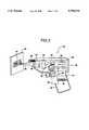
- FIG. 2is a longitudinal sectional view through a scanning device according to the present invention.
- FIG. 3is a basic optical layout.
- FIG. 4is the optical layout of the scanning device of the present invention.
- FIG. 5is a cut-out perspective view of the trigger mechanism of the scanning device of the present invention.
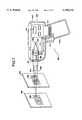
- FIG. 6is a block diagram of the operation of the scanning device of the present invention.
- FIG. 7is a longitudinal sectional view of a second embodiment of the scanning device.
- FIG. 8is the optical layout of the second embodiment of the scanning device.
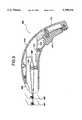
- FIG. 9is a longitudinal sectional view of a third embodiment of the scanning device.
- the scanning device 10includes a light source 12, a detector 14 and focusing optics 16. Since many hand-held scanning devices are held in the hand of an operator, they are generally gun-shaped to facilitate ease of use.
- a trigger 18is depressed to energize the light source 12 and illuminate the subject bar code 20.
- Light reflected from the bar code 20is focused by the focusing optics 16 onto the detector 14.
- the electronic image of the bar code 20 produced by the detector 14is then forwarded to a microprocessor (not shown) for further processing. Since the focusing optics 16 are fixed relative to the detector 14, the operator must move the entire scanning device 10 until the bar code 20 comes into focus. This method of focusing is extremely cumbersome.
- the scanning device 30includes a generally gun-shaped housing 32 having a handle 34, a body portion 36, a window 38 and a manually actuated trigger 40.
- the handle 34is contoured to comfortably fit within the hand of an operator. The operator grips the housing 32 by the handle 34 and aims the window 38 at the bar code symbol 44 to be read.
- the trigger 40is recessed within the handle 34 for easy one-handed operation of the scanning device 30.
- the trigger 40is positioned relative to the operator's fingers such that activation of the scanning device 30 is achieved by squeezing one's fingers and depressing the trigger 40.
- the trigger 40activates a light source 42, via a switch 39, to illuminate the bar code 44 located on a label 46.
- the light source 42comprises a plurality of light emitting diodes (LEDs).
- LEDslight emitting diodes
- the light source 42is mounted within the front portion of the housing 32 such that the light 48 is projected outward from the housing 32 to the bar code 44.
- a portion of the light that strikes the bar code 44is reflected 52, 54 from the bar code 44, back through the window 38, to the focusing optics 50.
- the lightis focused onto a detector 60, such as a photosensitive array, by the focusing optics 50.
- the photosensitive array 60is a charged coupled device (CCD).
- CCDcharged coupled device
- the light incident 52, 54 upon the detector 60produces an electronic image of the bar code 44.
- the detector 60then outputs the information to the signal processor 62 for further processing and decoding.
- the signal processor 62is preferably mounted within the body portion 36 of the scanning device 30.
- the optical arrangement of a typical scanning devicecan be defined by the thin lens formula: ##EQU1## where F equals the focal length of the lens 80, ID equals the image distance and OD equals the object distance.
- Fthe focal length of the lens 80
- IDthe image distance
- ODthe object distance.
- Light reflected by the object Owill be focused by the lens 80 to create an image I of the object O on the detector 82.
- An object O located at a distance OD from the lens 80will create an image I on the detector 82 at a distance ID from the lens 80. If the detector 82 is stationary, the object O must be brought to the specific distance OD from the lens 80 to be properly focused. It is often cumbersome and frustrating for the operator to properly locate and focus the scanning device on an object O in this manner.
- the optical arrangement 100 of the preferred embodiment of the present inventionis shown.
- the optics 102focus the reflected light onto a detector 104 which is moveable along the image path IP.
- the further O 2 an object to be scannedis from the optics 102, the closer D 2 the detector 104 must be to the optics 102.
- the objectmay be brought into focus by sweeping the detector 104 from ID 2 to ID 1 . Perfect focus is guaranteed at a minimum of one location along the trajectory on image path IP.
- the detector 60is moved along the image path 51 using an actuator 53 which comprises trigger 40, and gears 41, 43.
- the actuator 53is shown in greater detail in FIG. 5.
- the detector 60is operatively associated with the trigger 40 by two gears 41 and 43.
- the top portion of the trigger 40is provided with a plurality of crenellations 110.
- the crenellations 110cooperate with the first gear 41, which drives the second gear 43.
- the second gear 43further cooperates a plurality of crenellations 114 on a sliding platform 112.
- the detector 60is attached to, and supported by, the sliding platform 112.
- the crenellations 110intermesh with the teeth of the first gear 41, causing the first gear 41 to rotate.
- Thiscauses the second gear 43 to rotate and move the sliding platform 112.
- the detector 60moves backward in conjunction with the sliding platform 112.
- a spring 49biases the rear surface of the trigger 40, pushing the trigger 40 outward. Accordingly, the gears 41, 43 revolve in opposite directions, returning the detector 60 to its original position.
- actuator 53in its most basic form has been described. However, it should also be understood that the actuator 53 may be altered without departing from the spirit and scope of the present invention. For example, a direct mechanical connection may be employed between the trigger 40 and the detector 60.
- the detector 60consists of an array of equally spaced pixels. The spacing of the pixels determines the limit of the resolution of the detector 60, so it is necessary to match the CCD resolution to the desired resolution of the scanning device 30.
- the magnification of the optics 50should be chosen so at least two CCD pixels cover the minimum bar width to be resolved. This is particularly important for bar codes printed with a dot matrix printer.
- the detector 60In operation, as the trigger 40 is pulled and the detector 60 is moved along the image path 51, the detector 60 repeatedly captures scans (in a linear camera) or frames (in an area camera). As would be appreciated by those of skill in the art, the required scanning rate of the detector will depend upon the speed of the movement of the trigger 40 and the light level. Since the scanning rate of the detector 60 will be orders of magnitude faster than the speed of movement of the trigger 40, the object will be in focus for at least a few scans.
- a range detectormay be provided to detect if the object is placed outside the range of the detector 60.
- the multiple scansare tested for validity and accuracy.
- a high contrast testis performed.
- the contrast testdetermines the difference between the maximum and minimum gray scale values.
- the highest gray scale valuesindicate that the detector 60 is focused.
- Low gray scale valuesindicate that the detector 60 is improperly focused.
- a transition count test or other verification testmay be performed, as is known in the art.
- the operation of the scanning device 30 of the present inventionmay best be summarized with reference to FIG. 6.
- the operatorsqueezes the trigger 40 which activates the light source 42 and moves the CCD detector 60, (step 300).
- the lightstrikes the bar code 44, (step 310), and is then reflected back from the bar code 44, (step 320).
- the reflected lightis converged by the optics, (step 330).
- the CCD detector 60moves along the image path 51 and repetitively captures the reflected light at multiple points along the image path 51, (step 340).
- the detected imageis then analyzed and processed, (step 350).
- the scanning device 400includes a generally gun-shaped housing 410, a handle 416, a body portion 418, a detector 420, associated processing electronics 414, a return spring 411, a window 421 and a manually actuated trigger 412. Depressing the trigger 412 activates the scanning device 400 and energizes the light source 440. In this embodiment, however, the trigger 412 is operatively associated with the optics 424. The optics 424 move in response to the movement of the trigger 412, which sweeps the optics 424 along the image path.
- This embodimentoperates in a similar manner to the embodiment shown in FIG. 2. Focusing of the reflected light 442, 438 from the bar codes 456 and 458 located at different distances 454, 450 is guaranteed through the range of movement of the converging lens 424.
- the relationship of the optical elements in the scanning device 400can be described by Equation 1. Referring to FIG. 8, the object shown at points O 3 and O 4 can be focused on the image path IP by changing the distance between the lens 524 and the object O 3 , O 4 shown by lines OD 3 and OD 4 . The further the object is from the lens 524, the closer L 4 the lens 524 must be to the CCD detector 520. The closer the object is to the lens 524, the further L 3 the lens 524 must be from the CCD detector 520 as shown by line ID 3 .
- Sweeping the lens 524 along the image path IPguarantees focus at a minimum of one point along the path shown between points L 1 and L 2 of the lens 424.
- An object positioned at a distance of OD 3will focus on the detector 520 at image distance ID 3 .
- Varying the position of the lens 524 along the image path IPeffectively varies the image distance between ID 3 and ID 4 .
- An object positioned at distance OD 4will focus on the detector 520 at image distance ID 4 .
- FIG. 9a second alternate embodiment of the present invention is shown in FIG. 9 with an ergonomically shaped housing 610.
- the scanning device 600includes an ergonomically designed housing 610, a handle portion 616, and a manually actuated trigger 612. Similar to the above described embodiments, depressing the trigger 612 activates the scanning device 600 and energizes the light source 622.
- the trigger 612is operatively associated with the optics 624 via a linkage 615 that moves the optics 624 in response to the trigger 612 movement. The movement of the optics 624 then refocuses bar codes 654, 650 at different distances onto a detector 620.
Landscapes
- Physics & Mathematics (AREA)
- Electromagnetism (AREA)
- Engineering & Computer Science (AREA)
- Health & Medical Sciences (AREA)
- General Health & Medical Sciences (AREA)
- Toxicology (AREA)
- Artificial Intelligence (AREA)
- Computer Vision & Pattern Recognition (AREA)
- General Physics & Mathematics (AREA)
- Theoretical Computer Science (AREA)
- Facsimile Scanning Arrangements (AREA)
- Image Input (AREA)
Abstract
Description
Claims (20)
Priority Applications (4)
| Application Number | Priority Date | Filing Date | Title |
|---|---|---|---|
| US08/654,189US5798516A (en) | 1996-05-28 | 1996-05-28 | Focusing mechanism for hand-held CCD scanners |
| PCT/US1997/007536WO1997045808A1 (en) | 1996-05-28 | 1997-05-05 | Focusing mechanism for hand-held ccd scanners |
| AU28269/97AAU2826997A (en) | 1996-05-28 | 1997-05-05 | Focusing mechanism for hand-held ccd scanners |
| CA002227166ACA2227166C (en) | 1996-05-28 | 1997-05-05 | Focusing mechanism for hand-held ccd scanners |
Applications Claiming Priority (1)
| Application Number | Priority Date | Filing Date | Title |
|---|---|---|---|
| US08/654,189US5798516A (en) | 1996-05-28 | 1996-05-28 | Focusing mechanism for hand-held CCD scanners |
Publications (1)
| Publication Number | Publication Date |
|---|---|
| US5798516Atrue US5798516A (en) | 1998-08-25 |
Family
ID=24623819
Family Applications (1)
| Application Number | Title | Priority Date | Filing Date |
|---|---|---|---|
| US08/654,189Expired - Fee RelatedUS5798516A (en) | 1996-05-28 | 1996-05-28 | Focusing mechanism for hand-held CCD scanners |
Country Status (4)
| Country | Link |
|---|---|
| US (1) | US5798516A (en) |
| AU (1) | AU2826997A (en) |
| CA (1) | CA2227166C (en) |
| WO (1) | WO1997045808A1 (en) |
Cited By (12)
| Publication number | Priority date | Publication date | Assignee | Title |
|---|---|---|---|---|
| US5979769A (en)* | 1996-11-05 | 1999-11-09 | Psc Inc. | Combination range laser scanner utilizing periodic range switching |
| WO2001072028A1 (en)* | 2000-03-17 | 2001-09-27 | Accu-Sort Systems, Inc. | Coplanar camera scanning system |
| US6688525B1 (en) | 1999-09-22 | 2004-02-10 | Eastman Kodak Company | Apparatus and method for reading a coded pattern |
| US20040069855A1 (en)* | 2002-10-15 | 2004-04-15 | Mehul Patel | Imaging bar code reader with moving beam simulation |
| US20040118921A1 (en)* | 2002-12-18 | 2004-06-24 | Alex Breytman | Miniature auto focus piezo actuator system |
| US20050095552A1 (en)* | 1999-11-30 | 2005-05-05 | Peer Sporbert | Three-dimensional occlusal and interproximal contact detection and display using virtual tooth models |
| US6975352B2 (en) | 2000-12-18 | 2005-12-13 | Xerox Corporation | Apparatus and method for capturing a composite digital image with regions of varied focus and magnification |
| US20060098433A1 (en)* | 2000-03-17 | 2006-05-11 | Accu-Sort Systems, Inc. | Coplanar camera scanning system |
| US7190835B2 (en)* | 1996-06-21 | 2007-03-13 | Intermec Ip Corp. | Code reader performing coded image decoding using non-dedicated decode processor |
| US20090072039A1 (en)* | 2007-09-19 | 2009-03-19 | Toshiba Tec Kabushiki Kaisha | Code symbol reading apparatus |
| US20100142856A1 (en)* | 2008-12-10 | 2010-06-10 | Shin Takeuchi | Image reading apparatus, and reading method |
| US20250028088A1 (en)* | 2023-07-17 | 2025-01-23 | Datalogic Ip Tech S.R.L. | Multi-source illuminator |
Citations (21)
| Publication number | Priority date | Publication date | Assignee | Title |
|---|---|---|---|---|
| US3812459A (en)* | 1972-03-08 | 1974-05-21 | Optical Business Machines | Opticscan arrangement for optical character recognition systems |
| US4136821A (en)* | 1976-09-01 | 1979-01-30 | Nippondenso Co., Ltd. | Method and apparatus for recognizing code information |
| JPS6367692A (en)* | 1986-09-09 | 1988-03-26 | Nippon Denso Co Ltd | Optical information reader |
| US4877949A (en)* | 1986-08-08 | 1989-10-31 | Norand Corporation | Hand-held instant bar code reader system with automated focus based on distance measurements |
| JPH027182A (en)* | 1988-06-27 | 1990-01-11 | Matsushita Electric Ind Co Ltd | Barcode detection device |
| US5001509A (en)* | 1985-01-17 | 1991-03-19 | Minolta Camera Kabushiki Kaisha | Automatic focus adjusting apparatus |
| EP0425844A2 (en)* | 1989-10-30 | 1991-05-08 | Symbol Technologies, Inc. | Power saving scanning arrangement |
| US5070352A (en)* | 1987-04-17 | 1991-12-03 | Fuji Photo Film Co., Ltd. | Range finding device for cameras |
| US5192856A (en)* | 1990-11-19 | 1993-03-09 | An Con Genetics, Inc. | Auto focusing bar code reader |
| EP0548958A2 (en)* | 1991-12-23 | 1993-06-30 | Symbol Technologies, Inc. | Laser scanner device |
| US5281801A (en)* | 1989-10-30 | 1994-01-25 | Symbol Technologies, Inc. | Low-cost low-power scanner and method |
| US5302812A (en)* | 1991-12-23 | 1994-04-12 | Symbol Technologies, Inc. | Laser scanning device with automatic range and spot size adjustment |
| US5308964A (en)* | 1991-07-29 | 1994-05-03 | Kwon Young K | Variable resolution wand |
| US5308966A (en)* | 1986-08-08 | 1994-05-03 | Norand Corporation | Hand-held instant bar code reader having automatic focus control for operation over a range of distances |
| US5340971A (en)* | 1990-09-17 | 1994-08-23 | Metrologic Instruments, Inc. | Automatic bar code reading system having selectable long range and short range modes of operation |
| US5349172A (en)* | 1992-02-27 | 1994-09-20 | Alex Roustaei | Optical scanning head |
| US5359185A (en)* | 1992-05-11 | 1994-10-25 | Norand Corporation | Chromatic ranging method and apparatus for reading optically readable information over a substantial range of distances |
| US5378883A (en)* | 1991-07-19 | 1995-01-03 | Omniplanar Inc. | Omnidirectional wide range hand held bar code reader |
| US5386107A (en)* | 1991-12-23 | 1995-01-31 | Symbol Technologies, Inc. | Scanning arrangement and method in which the focus is varied in operative correlation with the scanning angle |
| US5397885A (en)* | 1993-01-11 | 1995-03-14 | Reflexion Plus | Hand-held barcode label reader with increased depth of field |
| US5438187A (en)* | 1991-11-01 | 1995-08-01 | Spectra-Physics Scanning Systems, Inc. | Multiple focus optical system for data reading applications |
- 1996
- 1996-05-28USUS08/654,189patent/US5798516A/ennot_activeExpired - Fee Related
- 1997
- 1997-05-05CACA002227166Apatent/CA2227166C/ennot_activeExpired - Fee Related
- 1997-05-05AUAU28269/97Apatent/AU2826997A/ennot_activeAbandoned
- 1997-05-05WOPCT/US1997/007536patent/WO1997045808A1/enactiveApplication Filing
Patent Citations (21)
| Publication number | Priority date | Publication date | Assignee | Title |
|---|---|---|---|---|
| US3812459A (en)* | 1972-03-08 | 1974-05-21 | Optical Business Machines | Opticscan arrangement for optical character recognition systems |
| US4136821A (en)* | 1976-09-01 | 1979-01-30 | Nippondenso Co., Ltd. | Method and apparatus for recognizing code information |
| US5001509A (en)* | 1985-01-17 | 1991-03-19 | Minolta Camera Kabushiki Kaisha | Automatic focus adjusting apparatus |
| US4877949A (en)* | 1986-08-08 | 1989-10-31 | Norand Corporation | Hand-held instant bar code reader system with automated focus based on distance measurements |
| US5308966A (en)* | 1986-08-08 | 1994-05-03 | Norand Corporation | Hand-held instant bar code reader having automatic focus control for operation over a range of distances |
| JPS6367692A (en)* | 1986-09-09 | 1988-03-26 | Nippon Denso Co Ltd | Optical information reader |
| US5070352A (en)* | 1987-04-17 | 1991-12-03 | Fuji Photo Film Co., Ltd. | Range finding device for cameras |
| JPH027182A (en)* | 1988-06-27 | 1990-01-11 | Matsushita Electric Ind Co Ltd | Barcode detection device |
| US5281801A (en)* | 1989-10-30 | 1994-01-25 | Symbol Technologies, Inc. | Low-cost low-power scanner and method |
| EP0425844A2 (en)* | 1989-10-30 | 1991-05-08 | Symbol Technologies, Inc. | Power saving scanning arrangement |
| US5340971A (en)* | 1990-09-17 | 1994-08-23 | Metrologic Instruments, Inc. | Automatic bar code reading system having selectable long range and short range modes of operation |
| US5192856A (en)* | 1990-11-19 | 1993-03-09 | An Con Genetics, Inc. | Auto focusing bar code reader |
| US5378883A (en)* | 1991-07-19 | 1995-01-03 | Omniplanar Inc. | Omnidirectional wide range hand held bar code reader |
| US5308964A (en)* | 1991-07-29 | 1994-05-03 | Kwon Young K | Variable resolution wand |
| US5438187A (en)* | 1991-11-01 | 1995-08-01 | Spectra-Physics Scanning Systems, Inc. | Multiple focus optical system for data reading applications |
| EP0548958A2 (en)* | 1991-12-23 | 1993-06-30 | Symbol Technologies, Inc. | Laser scanner device |
| US5302812A (en)* | 1991-12-23 | 1994-04-12 | Symbol Technologies, Inc. | Laser scanning device with automatic range and spot size adjustment |
| US5386107A (en)* | 1991-12-23 | 1995-01-31 | Symbol Technologies, Inc. | Scanning arrangement and method in which the focus is varied in operative correlation with the scanning angle |
| US5349172A (en)* | 1992-02-27 | 1994-09-20 | Alex Roustaei | Optical scanning head |
| US5359185A (en)* | 1992-05-11 | 1994-10-25 | Norand Corporation | Chromatic ranging method and apparatus for reading optically readable information over a substantial range of distances |
| US5397885A (en)* | 1993-01-11 | 1995-03-14 | Reflexion Plus | Hand-held barcode label reader with increased depth of field |
Cited By (23)
| Publication number | Priority date | Publication date | Assignee | Title |
|---|---|---|---|---|
| US7190835B2 (en)* | 1996-06-21 | 2007-03-13 | Intermec Ip Corp. | Code reader performing coded image decoding using non-dedicated decode processor |
| US5979769A (en)* | 1996-11-05 | 1999-11-09 | Psc Inc. | Combination range laser scanner utilizing periodic range switching |
| US6688525B1 (en) | 1999-09-22 | 2004-02-10 | Eastman Kodak Company | Apparatus and method for reading a coded pattern |
| US20050095552A1 (en)* | 1999-11-30 | 2005-05-05 | Peer Sporbert | Three-dimensional occlusal and interproximal contact detection and display using virtual tooth models |
| US8998608B2 (en)* | 1999-11-30 | 2015-04-07 | Orametrix, Inc. | Three-dimensional occlusal and interproximal contact detection and display using virtual tooth models |
| AU768621B2 (en)* | 2000-03-17 | 2003-12-18 | Accu-Sort Systems, Inc. | Coplanar camera scanning system |
| US9088683B2 (en) | 2000-03-17 | 2015-07-21 | Datalogic Automation, Inc. | Coplanar camera scanning system |
| US20040201875A1 (en)* | 2000-03-17 | 2004-10-14 | Accu-Sort Systems, Inc. | Coplanar camera scanning system |
| US6856440B2 (en) | 2000-03-17 | 2005-02-15 | Accu-Sort Systems, Inc. | Coplanar camera scanning system |
| US6628445B2 (en) | 2000-03-17 | 2003-09-30 | Accu-Sort Systems, Inc. | Coplanar camera scanning system |
| WO2001072028A1 (en)* | 2000-03-17 | 2001-09-27 | Accu-Sort Systems, Inc. | Coplanar camera scanning system |
| US20060098433A1 (en)* | 2000-03-17 | 2006-05-11 | Accu-Sort Systems, Inc. | Coplanar camera scanning system |
| US7548274B2 (en) | 2000-03-17 | 2009-06-16 | Accu-Sort Systems, Inc. | Coplanar camera scanning system |
| US6975352B2 (en) | 2000-12-18 | 2005-12-13 | Xerox Corporation | Apparatus and method for capturing a composite digital image with regions of varied focus and magnification |
| US20040069855A1 (en)* | 2002-10-15 | 2004-04-15 | Mehul Patel | Imaging bar code reader with moving beam simulation |
| US6866198B2 (en)* | 2002-10-15 | 2005-03-15 | Symbol Technologies, Inc. | Imaging bar code reader with moving beam simulation |
| US7083096B2 (en)* | 2002-12-18 | 2006-08-01 | Symbol Technologies, Inc. | Miniature auto focus piezo actuator system |
| US20040118921A1 (en)* | 2002-12-18 | 2004-06-24 | Alex Breytman | Miniature auto focus piezo actuator system |
| US20090072039A1 (en)* | 2007-09-19 | 2009-03-19 | Toshiba Tec Kabushiki Kaisha | Code symbol reading apparatus |
| US8066189B2 (en)* | 2007-09-19 | 2011-11-29 | Toshiba Tec Kabushiki Kaisha | Code symbol reading apparatus |
| US20100142856A1 (en)* | 2008-12-10 | 2010-06-10 | Shin Takeuchi | Image reading apparatus, and reading method |
| US20250028088A1 (en)* | 2023-07-17 | 2025-01-23 | Datalogic Ip Tech S.R.L. | Multi-source illuminator |
| US12422595B2 (en)* | 2023-07-17 | 2025-09-23 | Datalogic Ip Tech S.R.L. | Multi-source illuminator |
Also Published As
| Publication number | Publication date |
|---|---|
| AU2826997A (en) | 1998-01-05 |
| WO1997045808A1 (en) | 1997-12-04 |
| CA2227166C (en) | 2000-12-26 |
| CA2227166A1 (en) | 1997-12-04 |
Similar Documents
| Publication | Publication Date | Title |
|---|---|---|
| EP1573648B1 (en) | Image scanning device having a system for determining the distance to a target | |
| US7025273B2 (en) | Miniature auto focus voice coil actuator system | |
| EP1112547B1 (en) | Optical symbologies imager | |
| US6123264A (en) | Apparatus and method for determining a distance to a target | |
| US7854385B2 (en) | Automatic region of interest focusing for an imaging-based bar code reader | |
| US8328099B2 (en) | Auto-focusing method for an automatic data collection device, such as an image acquisition device | |
| US5798516A (en) | Focusing mechanism for hand-held CCD scanners | |
| JPH0696255A (en) | Improved-type optical reader | |
| US20080290169A1 (en) | Compact autofocus bar code reader with moving mirror | |
| US7083096B2 (en) | Miniature auto focus piezo actuator system | |
| US11308295B2 (en) | Handheld optical information reading device | |
| WO2006083531A2 (en) | Asymmetrical scanner | |
| WO2013026180A1 (en) | Optical code symbol reading system employing axicon-generated laser aiming beam | |
| US20070119948A1 (en) | Method of and control switch arrangement for controlling different operational states in an electro-optical reader | |
| JP3716315B2 (en) | Mark reader | |
| JP2005182117A (en) | Code reader | |
| JP4176007B2 (en) | Code reader having distance measuring function | |
| CN1038536C (en) | Light scanor with enlarged focal length | |
| AU2007203527B2 (en) | Image scanning device having a system for determining the distance to a target | |
| JP2005004423A (en) | Optical mouse | |
| KR930014155A (en) | Optical scanning device |
Legal Events
| Date | Code | Title | Description |
|---|---|---|---|
| AS | Assignment | Owner name:ACCU-SORT SYSTEMS, INC., PENNSYLVANIA Free format text:ASSIGNMENT OF ASSIGNORS INTEREST;ASSIGNOR:SHREESHA, VASANTH;REEL/FRAME:008050/0383 Effective date:19960716 | |
| FEPP | Fee payment procedure | Free format text:PAT HOLDER NO LONGER CLAIMS SMALL ENTITY STATUS, ENTITY STATUS SET TO UNDISCOUNTED (ORIGINAL EVENT CODE: STOL); ENTITY STATUS OF PATENT OWNER: LARGE ENTITY | |
| REFU | Refund | Free format text:REFUND - PAYMENT OF MAINTENANCE FEE, 4TH YR, SMALL ENTITY (ORIGINAL EVENT CODE: R283); ENTITY STATUS OF PATENT OWNER: LARGE ENTITY | |
| FPAY | Fee payment | Year of fee payment:4 | |
| FEPP | Fee payment procedure | Free format text:ENTITY STATUS SET TO UNDISCOUNTED (ORIGINAL EVENT CODE: BIG.); ENTITY STATUS OF PATENT OWNER: LARGE ENTITY | |
| AS | Assignment | Owner name:UNION NATIONAL BANK AND TRUST COMPANY OF SOUDERTON Free format text:SECURITY INTEREST;ASSIGNOR:ACCU-SORT SYSTEMS, INC.;REEL/FRAME:013333/0727 Effective date:20020627 | |
| REMI | Maintenance fee reminder mailed | ||
| LAPS | Lapse for failure to pay maintenance fees | ||
| STCH | Information on status: patent discontinuation | Free format text:PATENT EXPIRED DUE TO NONPAYMENT OF MAINTENANCE FEES UNDER 37 CFR 1.362 | |
| FP | Lapsed due to failure to pay maintenance fee | Effective date:20060825 |