US5797918A - Flexible surgical screwdriver and methods of arthroscopic ligament reconstruction - Google Patents
Flexible surgical screwdriver and methods of arthroscopic ligament reconstructionDownload PDFInfo
- Publication number
- US5797918A US5797918AUS08/554,601US55460195AUS5797918AUS 5797918 AUS5797918 AUS 5797918AUS 55460195 AUS55460195 AUS 55460195AUS 5797918 AUS5797918 AUS 5797918A
- Authority
- US
- United States
- Prior art keywords
- shaft portion
- linkage member
- flexible shaft
- screwdriver
- handle
- Prior art date
- Legal status (The legal status is an assumption and is not a legal conclusion. Google has not performed a legal analysis and makes no representation as to the accuracy of the status listed.)
- Expired - Fee Related
Links
- 210000003041ligamentAnatomy0.000titleabstractdescription44
- 238000000034methodMethods0.000titleabstractdescription24
- 210000000988bone and boneAnatomy0.000claimsabstractdescription209
- 238000005304joiningMethods0.000claimsdescription11
- 210000003127kneeAnatomy0.000description36
- 238000003780insertionMethods0.000description25
- 230000037431insertionEffects0.000description25
- 230000007246mechanismEffects0.000description21
- 210000000629knee jointAnatomy0.000description15
- 206010052428WoundDiseases0.000description10
- 238000001356surgical procedureMethods0.000description9
- 210000001519tissueAnatomy0.000description9
- 210000001264anterior cruciate ligamentAnatomy0.000description8
- 239000010935stainless steelSubstances0.000description8
- 229910001220stainless steelInorganic materials0.000description8
- 210000000689upper legAnatomy0.000description8
- 238000013459approachMethods0.000description6
- 239000000463materialSubstances0.000description6
- 238000010276constructionMethods0.000description5
- 208000027418Wounds and injuryDiseases0.000description4
- 230000001154acute effectEffects0.000description4
- 208000014674injuryDiseases0.000description4
- 230000033001locomotionEffects0.000description4
- 229910001000nickel titaniumInorganic materials0.000description4
- 210000004872soft tissueAnatomy0.000description4
- 210000002303tibiaAnatomy0.000description4
- 230000008878couplingEffects0.000description3
- 238000010168coupling processMethods0.000description3
- 238000005859coupling reactionMethods0.000description3
- 238000013461designMethods0.000description3
- 238000003306harvestingMethods0.000description3
- 210000000426patellar ligamentAnatomy0.000description3
- 230000002093peripheral effectEffects0.000description3
- 230000008733traumaEffects0.000description3
- 238000003466weldingMethods0.000description3
- 230000005540biological transmissionEffects0.000description2
- 238000007796conventional methodMethods0.000description2
- 238000012986modificationMethods0.000description2
- 230000004048modificationEffects0.000description2
- 239000004033plasticSubstances0.000description2
- 210000002967posterior cruciate ligamentAnatomy0.000description2
- 230000004044responseEffects0.000description2
- BCHLTFOMLWCYIS-UHFFFAOYSA-N4-amino-5-chloro-n-[2-(diethylamino)ethyl]-2-methoxybenzamide;n-(4-hydroxyphenyl)acetamide;hydrochlorideChemical compoundCl.CC(=O)NC1=CC=C(O)C=C1.CCN(CC)CCNC(=O)C1=CC(Cl)=C(N)C=C1OCBCHLTFOMLWCYIS-UHFFFAOYSA-N0.000description1
- ZOXJGFHDIHLPTG-UHFFFAOYSA-NBoronChemical group[B]ZOXJGFHDIHLPTG-UHFFFAOYSA-N0.000description1
- 0C*C1=C(CC[N+]([O-])=O)C1Chemical compoundC*C1=C(CC[N+]([O-])=O)C10.000description1
- 206010041899Stab woundDiseases0.000description1
- 229910000831SteelInorganic materials0.000description1
- 238000004026adhesive bondingMethods0.000description1
- 210000001188articular cartilageAnatomy0.000description1
- 238000005234chemical depositionMethods0.000description1
- 238000004140cleaningMethods0.000description1
- 238000004891communicationMethods0.000description1
- 230000000295complement effectEffects0.000description1
- 210000002808connective tissueAnatomy0.000description1
- 230000006378damageEffects0.000description1
- 230000003247decreasing effectEffects0.000description1
- 230000003111delayed effectEffects0.000description1
- 230000008030eliminationEffects0.000description1
- 238000003379elimination reactionMethods0.000description1
- 239000000835fiberSubstances0.000description1
- 230000035876healingEffects0.000description1
- 238000007373indentationMethods0.000description1
- 238000010147laser engravingMethods0.000description1
- 238000010329laser etchingMethods0.000description1
- 238000004519manufacturing processMethods0.000description1
- 210000000412mechanoreceptorAnatomy0.000description1
- 108091008704mechanoreceptorsProteins0.000description1
- 239000002991molded plasticSubstances0.000description1
- 238000002355open surgical procedureMethods0.000description1
- 230000000149penetrating effectEffects0.000description1
- 230000002035prolonged effectEffects0.000description1
- 230000003068static effectEffects0.000description1
- 239000010959steelSubstances0.000description1
- 230000001954sterilising effectEffects0.000description1
- 238000004659sterilization and disinfectionMethods0.000description1
- 238000012546transferMethods0.000description1
- 230000000007visual effectEffects0.000description1
- 238000012800visualizationMethods0.000description1
Images


Classifications
- A—HUMAN NECESSITIES
- A61—MEDICAL OR VETERINARY SCIENCE; HYGIENE
- A61F—FILTERS IMPLANTABLE INTO BLOOD VESSELS; PROSTHESES; DEVICES PROVIDING PATENCY TO, OR PREVENTING COLLAPSING OF, TUBULAR STRUCTURES OF THE BODY, e.g. STENTS; ORTHOPAEDIC, NURSING OR CONTRACEPTIVE DEVICES; FOMENTATION; TREATMENT OR PROTECTION OF EYES OR EARS; BANDAGES, DRESSINGS OR ABSORBENT PADS; FIRST-AID KITS
- A61F2/00—Filters implantable into blood vessels; Prostheses, i.e. artificial substitutes or replacements for parts of the body; Appliances for connecting them with the body; Devices providing patency to, or preventing collapsing of, tubular structures of the body, e.g. stents
- A61F2/02—Prostheses implantable into the body
- A61F2/08—Muscles; Tendons; Ligaments
- A61F2/0805—Implements for inserting tendons or ligaments
- A—HUMAN NECESSITIES
- A61—MEDICAL OR VETERINARY SCIENCE; HYGIENE
- A61B—DIAGNOSIS; SURGERY; IDENTIFICATION
- A61B17/00—Surgical instruments, devices or methods
- A61B17/14—Surgical saws
- A61B17/15—Guides therefor
- A—HUMAN NECESSITIES
- A61—MEDICAL OR VETERINARY SCIENCE; HYGIENE
- A61B—DIAGNOSIS; SURGERY; IDENTIFICATION
- A61B17/00—Surgical instruments, devices or methods
- A61B17/16—Instruments for performing osteoclasis; Drills or chisels for bones; Trepans
- A61B17/17—Guides or aligning means for drills, mills, pins or wires
- A61B17/1714—Guides or aligning means for drills, mills, pins or wires for applying tendons or ligaments
- A—HUMAN NECESSITIES
- A61—MEDICAL OR VETERINARY SCIENCE; HYGIENE
- A61B—DIAGNOSIS; SURGERY; IDENTIFICATION
- A61B17/00—Surgical instruments, devices or methods
- A61B17/56—Surgical instruments or methods for treatment of bones or joints; Devices specially adapted therefor
- A61B17/58—Surgical instruments or methods for treatment of bones or joints; Devices specially adapted therefor for osteosynthesis, e.g. bone plates, screws or setting implements
- A61B17/88—Osteosynthesis instruments; Methods or means for implanting or extracting internal or external fixation devices
- A61B17/8875—Screwdrivers, spanners or wrenches
- B—PERFORMING OPERATIONS; TRANSPORTING
- B25—HAND TOOLS; PORTABLE POWER-DRIVEN TOOLS; MANIPULATORS
- B25B—TOOLS OR BENCH DEVICES NOT OTHERWISE PROVIDED FOR, FOR FASTENING, CONNECTING, DISENGAGING OR HOLDING
- B25B13/00—Spanners; Wrenches
- B25B13/48—Spanners; Wrenches for special purposes
- B25B13/481—Spanners; Wrenches for special purposes for operating in areas having limited access
- B—PERFORMING OPERATIONS; TRANSPORTING
- B25—HAND TOOLS; PORTABLE POWER-DRIVEN TOOLS; MANIPULATORS
- B25B—TOOLS OR BENCH DEVICES NOT OTHERWISE PROVIDED FOR, FOR FASTENING, CONNECTING, DISENGAGING OR HOLDING
- B25B23/00—Details of, or accessories for, spanners, wrenches, screwdrivers
- B25B23/0007—Connections or joints between tool parts
- B25B23/0021—Prolongations interposed between handle and tool
- B—PERFORMING OPERATIONS; TRANSPORTING
- B25—HAND TOOLS; PORTABLE POWER-DRIVEN TOOLS; MANIPULATORS
- B25G—HANDLES FOR HAND IMPLEMENTS
- B25G1/00—Handle constructions
- B25G1/04—Handle constructions telescopic; extensible; sectional
- B25G1/043—Handle constructions telescopic; extensible; sectional for screwdrivers, wrenches or spanners
- B—PERFORMING OPERATIONS; TRANSPORTING
- B25—HAND TOOLS; PORTABLE POWER-DRIVEN TOOLS; MANIPULATORS
- B25G—HANDLES FOR HAND IMPLEMENTS
- B25G3/00—Attaching handles to the implements
- B25G3/02—Socket, tang, or like fixings
- B25G3/12—Locking and securing devices
- B25G3/26—Locking and securing devices comprising nails, screws, bolts, or pins traversing or entering the socket
- A—HUMAN NECESSITIES
- A61—MEDICAL OR VETERINARY SCIENCE; HYGIENE
- A61B—DIAGNOSIS; SURGERY; IDENTIFICATION
- A61B17/00—Surgical instruments, devices or methods
- A61B17/16—Instruments for performing osteoclasis; Drills or chisels for bones; Trepans
- A61B17/17—Guides or aligning means for drills, mills, pins or wires
- A61B17/1739—Guides or aligning means for drills, mills, pins or wires specially adapted for particular parts of the body
- A61B17/1764—Guides or aligning means for drills, mills, pins or wires specially adapted for particular parts of the body for the knee
- A—HUMAN NECESSITIES
- A61—MEDICAL OR VETERINARY SCIENCE; HYGIENE
- A61B—DIAGNOSIS; SURGERY; IDENTIFICATION
- A61B17/00—Surgical instruments, devices or methods
- A61B17/16—Instruments for performing osteoclasis; Drills or chisels for bones; Trepans
- A61B17/17—Guides or aligning means for drills, mills, pins or wires
- A61B17/1796—Guides or aligning means for drills, mills, pins or wires for holes for sutures or flexible wires
- A—HUMAN NECESSITIES
- A61—MEDICAL OR VETERINARY SCIENCE; HYGIENE
- A61B—DIAGNOSIS; SURGERY; IDENTIFICATION
- A61B90/00—Instruments, implements or accessories specially adapted for surgery or diagnosis and not covered by any of the groups A61B1/00 - A61B50/00, e.g. for luxation treatment or for protecting wound edges
- A61B90/03—Automatic limiting or abutting means, e.g. for safety
- A61B2090/033—Abutting means, stops, e.g. abutting on tissue or skin
Definitions
- the present inventionpertains to surgical screwdrivers for inserting bone screws and, more particularly, to surgical screwdrivers for inserting interference bone fixation screws in bone tunnels and to methods of performing arthroscopic cruciate ligament reconstruction of the knee.
- fixation deviceused to fixate ligaments within bone tunnels during cruciate ligament reconstruction of the knee.
- a surgical screwdriveris commonly used to insert bone screws.
- This form of screwdriverhas a rotatable drive shaft for rotating the screw, and advancing it along the longitudinal axis of the driver.
- the drivercooperatively engages with a drive recess, within the interference screw, to help achieve axial alignment of the screw with the drive shaft of the screwdriver.
- the interference screwis inserted into tandem isometrically positioned bone tunnels formed in the tibia and femur.
- a prosthetic ligament graft affixed to bone blocks at each endis inserted into the bone tunnel such that the ligament extends across the knee joint in the anatomical position of the cruciate ligament.
- the bone blocksare fixated within the bone tunnel by interference screws.
- Each interference screwis inserted in the bone tunnel so as to be disposed laterally between the walls of the bone tunnel and the bone block.
- Successful cruciate ligament reconstructiondepends on the proper insertion of the interference screw along the longitudinal axis of the bone tunnel, parallel to both the tunnel walls and the bone block.
- Cruciate ligament reconstructionis commonly performed as an open surgical procedure. Incisions on the order of 10 inches in length are utilized to access the knee joint. These relatively long incisions are required to provide room for the surgical screwdriver to approach the tibial and femoral bone tunnels from directions aligned with the longitudinal axes of the bone tunnels and thereby to permit the driver to drive the interference screws effectively in a direction parallel with the bone block and the walls of the bone tunnels.
- Open surgerypossesses numerous disadvantageous compared to closed surgery or less invasive (arthroscopic) surgery for ligament reconstruction. These disadvantages include possible violation of mechanoreceptors in the knee, desiccation of articular cartilage of the joint, increased tissue trauma resulting from incisions accompanied by increased patient discomfort and delayed post surgical mobility. In addition, hospitalization and rehabilitation times may be prolonged.
- Narrow portalsare made with a puncture or stab wound in tissue adjacent to the knee of sufficient size to permit insertion of surgical instruments at the knee joint with the knee being visualized with an arthroscope.
- An arthroscopeis here defined as any instrument for insertion into the cavity of a joint in order to inspect its contents.
- An example of an arthroscopeis a fiberscope, which uses fiber optics to transmit images from the interior of the joint.
- a method of arthroscopic cruciate ligament reconstructioncan provide many benefits over open surgery, including reduced tissue trauma, decreased patient discomfort, earlier and aggressive range of motion and weight bearing without loss of fixation, reduced rehabilitation time and elimination of hospitalization because the procedures can be performed on an out-patient basis.
- the anteromedial and anterolateral portalsare angularly offset from the longitudinal axis of the femoral bone tunnel and therefore the direction of approach from such portals to the femoral bone tunnel to insert an interference screw is angularly offset also.
- the femoral bone tunnelopens on the femoral condyle at a site near the attachment site of the cruciate ligament. Longitudinal alignment of the screwdriver with the opening of the femoral bone tunnel on the femoral condyle is difficult using conventional surgical drivers when the approach is made through the arthroscopic portals. This in turn presents difficulties in driving the screw parallel with the longitudinal axis of the femoral bone tunnel and the bone block in the tunnel.
- interference screwscan be inserted through openings in the femoral condyle after their introduction through the tibial bone tunnels.
- Angled drivershave been used in industrial applications as wrenches and screwdrivers, and exemplary of such devices are U.S. Pat. Nos. 4,643,052 to Badiali, 4,620,458 to Schmidek, 3,788,169 to Nakayama, 3,696,694 to Boro, 3,604,486 to Henry, 3,232,151 to Blachowski, 2,042,376 to Balga, 1,428,282 to Glabaznya, 1,398,116 to Root, 1,199,823 to Sadtler, 933,639 to Frink and 877,571 to Larson.
- angled drivershave been used in power tools such as drills, and U.S. Pat. Nos. 5,041,119 to Frigg et al and 4,947,942 to Lightle et al are illustrative of angled, surgical power drills.
- Prior art angled surgical driversare unsuitable for use in least invasive, or endoscopic, surgical procedures to insert interference screws in bone tunnels directly from portals not aligned parallel with longitudinal axes of the bone tunnels. Moreover, angled surgical drivers in the prior art cannot effectively hold screws captive for insertion into the body through endoscopic size portals.
- the present inventionprovides, in one embodiment, a flexible surgical screwdriver for driving an interference screw into bone so that the screw is securely supported by the driver until insertion has been completed.
- the flexible surgical driverpermits access from an arthroscopic portal not aligned parallel with a longitudinal axis of the bone tunnel to place the interference screw parallel with the walls of the bone tunnel and the bone block while driving the screw from a direction angularly disposed with the tunnel wall.
- One embodimenthas a flexible shaft, a handle mounted to the flexible shaft for applying rotational force to the shaft, and a drive head mounted on the flexible shaft.
- the flexible shaft and handleare cannulated according to an embodiment for use with cannulated interference screws.
- the cannulated screw and driverare guided over a guide wire into position along the bone tunnel wall.
- the flexible shaftmay be formed by a plurality of linkage members disposed in series. Each linkage member is joined to an adjacent linkage member so as to permit adjacent linkage members to be pivotally movable with respect to one another about a pivot axis while maintaining the ability to transmit torque upon the rotation of the handle.
- An alternative embodiment of a screwdriver in accordance with the present invention permitting access from an arthroscopic portal not aligned parallel with a bone tunnelis an angled driver.
- the drive shaftis mounted on the operating shaft at an angle of approximately 20° with respect to the longitudinal axis of the operating shaft.
- An indicator on the handleallows orientation of the drive tip to be identified externally of the body, when the drive tip is inserted in the body through portals of minimal size.
- the angled drivermay be used without being cannulated.
- a retaining mechanism for holding a cannulated interference screw captive on the drive shaft prior to screw insertionincludes a wire having a proximal cylindrical section secured in a passage in the drive tip aligned with the longitudinal axis of the drive shaft and a distal cylindrical section that protrudes beyond the drive tip to be received in the cannula of the interference screw.
- the distal cylindrical section of the retaining mechanismis formed with a thermally set, slight curve or kink to hold the screw temporarily in place on the drive tip.
- the procedure in accordance with a preferred embodiment of the present inventionadvantageously eliminates the step of penetrating the lateral femoral cortex and permits a countersink of the screw below the opening of the femoral bone tunnel on the femoral condyle.
- the procedurecan be performed with fewer and smaller portals.
- the anteromedial and anterolateral portals formed for procedures preparatory to graft fixationcan be utilized to directly insert bone screws in femoral bone tunnels.
- hyperflexion of the knee in arthroscopic anterior cruciate ligament reconstructioncan be eliminated.
- the surgical instrument provided in a preferred embodiment of the inventionis designed to avoid drive shaft breakage, loss of interference screws at the knee joint, and to enhance screw insertion and driver positioning. In addition, screw divergence is minimized and maximum thread purchase along the length of the bone block is ensured.
- the embodimentis of unified construction for easy cleaning and sterilization with right and left knee compatibility. The embodiment employs a lightweight, ergonomic handle providing a balanced feel for the surgeon.
- FIG. 1is a broken side view, partly in longitudinal section, of an embodiment of an angled surgical screwdriver according to the present invention, showing an interference screw mounted on the screwdriver;
- FIG. 2is an exploded, broken side view, partly in section, of the distal end of the angled surgical screwdriver of FIG. 1;
- FIG. 3is a front view, partly in section, of the joint of a right knee positioned at substantially 900, showing the angled surgical screwdriver of FIG. 1 approaching an open end femoral bone tunnel via an anterolateral portal;
- FIG. 3Ais a top view of the angled surgical screwdriver of FIG. 1;
- FIG. 4is a broken side view, partly in section, of the drive shaft of a related embodiment of an angled surgical screwdriver according to the present invention, showing a retaining mechanism on the drive shaft and an end of a forming tool for mounting the retaining mechanism on the drive shaft;
- FIG. 5is a front view, partly in section, of the knee, joint of a right knee positioned at substantially 90o, showing the angled surgical screwdriver of FIG. 4 inserting a bone screw in a closed end femoral bone tunnel via an anteromedial portal;
- FIG. 6is a broken side view of the distal end of a further embodiment of an angled surgical screwdriver according to the present invention.
- FIG. 7is a broken side view, partly in section, of the drive shaft for the angled surgical screwdriver of FIG. 6;
- FIG. 8is a broken side view of the distal end of another embodiment of an angled surgical screwdriver according to the present invention.
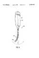
- FIG. 9is an isometric view of a cannulated flexible screwdriver of the present invention.
- FIG. 10is an isometric view of a curved cannula for use with the screwdriver of FIG. 9;
- FIG. 11is a broken view of an alternate embodiment of the curved cannula of FIG. 10;
- FIG. 12is a plan view of a further embodiment of a cannulated flexible screwdriver of the present invention.
- FIG. 13is an exploded view of the screwdriver of FIG. 12;
- FIG. 14is a front view, partly in section, of the joint of a knee, showing the screwdriver of FIG. 9 approaching a femoral tunnel via a curved cannula inserted through an anterolateral portal;
- FIG. 15is an isometric view of a cannulated flexible screwdriver in accordance with another embodiment of the present invention.
- FIG. 16shows the screwdriver of FIG. 15 in a flexed position
- FIG. 17is an isometric view of a flexible shaft portion for use with the screwdriver of FIG. 15;
- FIG. 18Ais a side view of a linkage member of the flexible shaft portion shown in FIG. 17;
- FIG. 18Bis a top end view of the linkage member shown in FIG. 18A;
- FIG. 19Ais an alternate side view of the linkage member shown in FIG. 18A having been rotated by 90 degrees about its longitudinal bore;
- FIG. 19Bis a bottom end view of the linkage member shown in FIG. 19A;
- FIGS. 20A-Bshow a ring for use with the flexible shaft portion shown in FIG. 17.
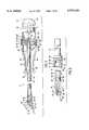
- FIG. 1An angled surgical screwdriver 10 according to an embodiment of the present invention is illustrated in FIG. 1, and includes an elongate operating shaft 12 with a distal end 16 coupled to a drive shaft 14 and a proximal end 24 on which is mounted a movable portion of handle 22.
- a sleeve 18Concentrically disposed around the operating shaft 12 is a sleeve 18, having a distal end 42, on which is mounted a drive head housing 20 and a proximal end 44 secured in a fixed portion of handle 22.
- Turning the movable portion of handle 22 with respect to the fixed portion thereofcauses rotation of the drive shaft 14, which is disposed at an angle of approximately 20° from the axis of rotation of handle 22.
- the operation of the screwdriver 12is described in further detail below.
- the operating shaft 12is preferably made of stainless steel with a cylindrical body terminating, at the distal end 16, at a distal end wall 30. Fitted concentrically around the distal end 16 is a cylindrical barrel 28, detail of which is shown in FIG. 2. A socket 32 is formed distally in barrel 28 in axial alignment with a longitudinal axis of the operating shaft 12 and, therefore, the longitudinal axis of the driver 10, as shown in FIGS. 1 and 2.
- Socket 32includes successively a tapered distal recess 34 at end wall 30, an intermediate recess 36, having a hexagonal configuration in cross-section, a cylindrical recess 38, and a conical proximal recess 40.
- the recessesare contiguous.
- Intermediate recess 36is formed of six flat sides extending longitudinally in the barrel 28 from distal recess 34 to cylindrical recess 38.
- the cylindrical recess 38has a diameter smaller than the diametric, cross-sectional dimension of the intermediate recess 36.
- a ball mechanism 56includes a cylindrical flange 64 joined to cylindrical neck 54, a curved neck 66 extending proximally from flange 64, and a ball 68 mounted on curved neck 66.
- the cylindrical flange 64has an outer diameter that is substantially the same as the outer diameter of the cylindrical body 48 and larger than the diameter of the cylindrical neck 54, such that an annular recess is defined concentrically around the cylindrical neck 54 laterally between the body 48 and the flange 64 of the drive shaft 14.
- the ball 68has a hexagonal configuration in cross-section, being formed of six curved surfaces extending proximally from curved neck 66 to an end surface 70.
- Ball 68is configured to be received in socket 32 of the operating shaft 12 with the longitudinal axis of the drive shaft 14 disposed at an acute angle of approximately 20° with respect to the longitudinal axis of the operating shaft 12. Engagement of the ball 68 in the socket 32 causes rotation of the drive shaft 14 in response to rotation of the operating shaft 12.
- Drive shaft 14is preferably made of stainless steel and, as shown in FIGS. 1 and 2, includes a cylindrical body 48, a drive tip 52, and the ball mechanism 56, in axial alignment.
- the cylindrical body 48is joined to the drive tip 52 at the distal end of a shoulder 50 tapered in a distal direction, the proximal end of shoulder 50 joining a neck 54, which in turn proximally joins the cylindrical body 48 to the ball mechanism 56.
- the drive tip 52has a distally tapered shoulder 58 terminating distally at an annular, peripheral lip 60, and a cylindrical passage 62 is formed in the drive tip 52 to extend proximally, longitudinally from lip 60 in axial alignment with the longitudinal axis of the drive shaft.
- the drive tip 52frictionally secure the end of a length of guide wire 72, such as a nickel-titanium alloy wire, as will be explained below, as shown in FIG. 1.
- Another purpose of the drive tipis to frictionally engage a screw.
- the drive tip 52has an external configuration to frictionally engage a drive recess 143 of an interference bone fixation screw 144.
- the drive tip 52can have various cross-sectional configurations--for example, multi-lobed or pronged, or hexagonal--corresponding to the configuration of the drive recess 143 of the fixation screw 144, so the screw will be rotated in bone with rotation of the drive shaft 14.
- the cylindrical body 48may be formed with the same cross-sectional configuration as, but slightly greater dimensions than, the drive tip 52, so as to frictionally engage the drive recess 143 of the screw 144, when, as shown in FIG. 1, the drive tip 52 is inserted deeply enough into the screw 144 to cause the body 48 portion to enter the drive recess 143.
- the drive shaft 14is prevented from being inserted into the drive recess 143 so far that the drive head housing 20 contacts the proximal end of screw 144.
- the back end of the screw 144is spaced distally from the drive head housing 20 to allow a portion (approximately 5 mm in one preferred embodiment) of the drive shaft 14 beyond the drive head housing 20 to be exposed. The exposed portion permits the screw 144 to be countersunk into a bone tunnel by an approximate additional amount equal to the length of the exposed portion.
- the back end of the screwcan be made to terminate distally of the drive head housing 20 in various ways. These include (a) making the distance from the lip 60 to the drive head housing 20 less than the length of the drive recess 143; or (b) forming the drive shaft 14 with external configurations or diametric dimensions limiting the distance that the drive shaft 14 can be inserted in the drive recess 143; or (c) providing a retaining mechanism on the drive shaft 14 that limits the distance that the drive shaft 14 can be inserted in the drive recess 143 as will be explained further below.
- Drive head housing 20is preferably made of stainless steel and includes a cylindrical section 74 and a distally tapered nose section 76 joined to the cylindrical section 74 at a bend 78, the nose section 76 extending angularly, distally from the cylindrical section 74.
- the wall of the cylindrical section 74has a thickness that is substantially constant along the length of the cylindrical section with an inner diameter sized to closely receive the outer diameters of the cylindrical barrel 28 and the sleeve 18.
- the wall of the nose section 76has a thickness that is greater than the wall thickness of the cylindrical section 74 at bend 78 to define an internal shoulder 80 serving as a stop for cylindrical barrel 28 when operating shaft 12 is disposed within the cylindrical section 74.
- the wall thickness of the nose section 76tapers in a distal direction such that an internal, cylindrical passage of substantially constant cross-section is defined along the length of the nose section.
- the cylindrical passage of the nose section 76is disposed at an angle with respect to the longitudinal axis of the cylindrical passage of the cylindrical section 74 that the angle of the drive shaft 14 with respect to the operating shaft 12.
- a C-shaped clip 82is mounted (by welding, for example, or simply by appropriate dimensions) in an annular slot in the nose section 76 and is received in the annular recess around neck 54 to prevent axial movement of the drive shaft 14 while allowing the drive shaft to rotate within the housing 20.
- the angled driver 150is substantially the same as the angled driver 10 of FIG. 1, except that a retaining mechanism 152, for holding an interference bone fixation screw captive on the driver prior to insertion of the screw, is mounted on drive shaft 14.
- Retaining mechanism 152includes a length of wire 154 (identified in FIGS. 6 and 8), such as a nickel-titanium alloy wire, having a proximal cylindrical section 156, which is joined to neck 160 at a shoulder 162, and a distal cylindrical section 158 joined to the proximal cylindrical section 156 by neck 160.
- the neck 160has an outer diameter that is smaller than the outer diameters of the proximal and distal cylindrical sections, which in turn are slightly smaller than the diameter of the cannula 145 in the interference bone fixation screw 144.
- the outer diameter of the proximal cylindrical section 156is sufficient to be received in the passage 62 in the drive tip 52 of drive head 14.
- the distal cylindrical section 158is formed with a thermally set, slight radius curve along its length.
- the length of the wire 154 that protrudes beyond the drive tip 52 when the proximal cylindrical section 156 is received thereinis selected to allow the curved distal cylindrical section 158 to be disposed in the cannula 145 of the screw 144 and to provide frictional engagement with the walls forming the cannula 145 when the screw is placed upon the drive shaft 14, such as shown in FIG. 8.
- the wire 154is mounted on the drive shaft 14 by press fitting the proximal cylindrical section 156 in the passage 62 of the drive tip 52 in a manner such that the neck 160 is aligned with edge 60 of drive tip 52. In some instances, depending on the material from which tip 152 is made, a press fit is sufficient and there is no need for neck 160 or shoulder 162. In other instances, when a neck and shoulder structure is used, a forming tool 164 is useful.
- Forming tool 164has a longitudinal cavity 166 terminating at a recess 168 tapered in the distal direction.
- the forming tool 164is moved along the wire 154 in the direction of the drive shaft 14 until the end wall 170 abuts the drive tip 52. In that position, the forming tool is urged against the tip 52, and the forming tool's tapered recess 168 forces the lip 60 to grip neck 160, and this grip, along with the shoulder 160, prevent the wire 154 from falling out of the drive shaft 14.
- the retaining mechanism 152may be used on drivers having drive tips axially aligned with longitudinal axes of the drivers to hold a screw upon the drivers prior to screw insertion, and the retaining mechanism 152 is not limited to use with angled drivers.
- the retaining mechanism 152may also be constructed in such a way that the fit of the wire 154 in the cannula 145 of screw 144 limits the depth that the drive shaft 14 may be inserted into the drive recess 143.
- the proximal end 24 of the operating shaft 12extends beyond the proximal end 44 of the sleeve 18.
- a cylindrical aperture 46 to receive a set screwis formed in the proximal extension and is disposed radially with respect to the longitudinal axis of the operating shaft 12.
- the sleeve 18has an outer diameter substantially the same as the outer diameter of barrel 28 at the distal end of the sleeve to form a smooth external profile with the barrel.
- the sleeve 18has an inner diameter sized to closely receive the outer diameter of the operating shaft 12 while still permitting the operating shaft 12 to rotate relative to the sleeve 18.
- Handle 22is preferably made of stainless steel and includes a forward static handle section 84, securing sleeve 18, and a rearward movable handle section 86, rotatable relative to the forward section 84.
- Forward handle section 84is of hollow construction and has a cylindrical wall 88 defining an open proximal end and a tapered wall 90 distally joined to cylindrical wall 88 and terminating at a front wall 92.
- Wall 90is tapered in a distal direction and is flared adjacent to front wall 92 to define an external profile that facilitates grasping during use.
- Concentric ribs 94are provided along an external surface of the forward handle section 84 to facilitate gripping during use.
- a cylindrical bushing 96is disposed in the open proximal end of the forward handle section 84.
- the bushing 96has an annular, peripheral flange 98 at a forward face thereof abutting an internal annular shoulder 100 of the cylindrical wall 88.
- a central openingis formed in bushing 96 for securing the proximal end 44 of the sleeve 18 therein.
- Bushing 96 and sleeve 18are preferably welded to the forward handle section 84 to form a sealed, water-tight cavity.
- Rearward handle section 86is of hollow construction, having a cylindrical wall 102 defining an open distal end that is closed by end cap 104.
- a cylindrical bushing 106is disposed in the open distal end of the rearward handle section 86.
- the bushing 106has an annular, peripheral flange 108 at a forward face thereof, and annular rim 110, extending axially in a direction distal from the flange 108, and a central, cylindrical protrusion 112 extending in a proximal direction.
- the bushing 106is axially in disposed in the open face front end of the rearward handle section 86 with flange 108 abutting an internal shoulder 114 of cylindrical wall 102.
- bushing 106An axial cavity is formed in bushing 106, extending proximally from the forward face thereof into the protrusion 112, for mounting the proximal end 24 of the operating shaft 12.
- Bushing 106is preferably welded to the rearward handle section 86 to form a sealed, water-tight cavity.
- Longitudinal ridges 116are provided along an external surface of the rearward handle section 86 to facilitate gripping during use.
- a pair of set screws 120is used to couple the rearward handle section 86 to the operating shaft 12.
- the screwsare disposed in a cylindrical passage formed in the bushing 106, radially disposed with respect to the longitudinal axis of the operating shaft 12 and in communication with the axial cavity of the bushing, the cylindrical passage being aligned with an opening in the cylindrical wall of 102 of the rearward handle section 86.
- the forward handle section 84is assembled with the rearward handle section 86, in such a way that the cylindrical wall 88 within the distal end of the forward handle section 84 abuts the cylindrical wall 102 of the rearward handle section 86 at a junction 124.
- a ring 126preferably made of stainless steel, is disposed concentrically around the handle 22 to extend over the junction 124, the ring 126 being mounted in grooves in the forward and rearward handle sections, while creating a stainless to stainless bearing surface that minimizes friction between the relatively movable components of the handle 22, to provide a good tactile response during use.
- a thrust washer 122is disposed concentrically within rim 110 abutting the forward face of the bushing 106 such that the rearward handle section 86 can be assembled with the forward handle section 84 with the thrust washer 122 abutting a rearward face of bushing 96 and rim 110 extending along the cylindrical wall 88 within the distal end of the forward handle section 84.
- Handle 22is of lightweight, ergonomic construction to provide a balanced feel for a surgeon during use. During use, upon rotation of the rearward handle section 86 relative to the forward handle section 84, the operating shaft 12 will be rotated relative to sleeve 18, causing rotation of drive shaft 14 and the drive tip 52.
- indicator 127is provided along an external surface of the forward handle section 84 to indicate, from a position external of the body, the orientation of the drive tip 52 when inserted in the body through an endoscopic portal.
- the indicator 127is disposed on the same side of handle 22 as the drive tip 52 and is aligned with the drive tip 52 and the longitudinal axis of the surgical screwdriver 10 such that, with the indicator 127 facing a surgeon, the drive tip 52 will be oriented in a direction angularly upward relative to the longitudinal axis of the surgical screwdriver.
- the indicator 127may utilize a wide range of suitable symbols, including arrows, lines or dots, and may be formed on the handle in diverse ways, such as by laser etching, engraving, or chemical deposition. Where formed as an indentation in the surface of the forward handle section 84, the indicator 127 can provide a tactile, as well as a visual, indication of the position of the drive tip 52.
- the angled driver of the embodiment described hereinincludes numerous design features that facilitate its use in arthroscopic anterior cruciate ligament reconstruction.
- the walls of the cylindrical section 74 and the nose section 76have a minimal thickness to reduce the overall outer diameter of the angled surgical screwdriver 10 in the area of bend 78, and the distance that the angled surgical screwdriver 20 protrudes distally beyond bend 78 is minimized to enhance maneuverability of the driver within the close confines of the knee joint and to allow the use of smaller portals in arthroscopic cruciate ligament reconstruction.
- the minimal diametric dimension and distal taper of the nose sectionfacilitate insertion of the driver in bone tunnels, allowing the drive shaft 14 to be inserted in bone tunnels up to bend 78.
- Shoulders 50 and 58give the drive head 14 a distal taper, facilitating insertion in portals of minimal size and additionally enhance maneuverability at the knee joint.
- the drive shaft 14protrudes beyond the back end of the bone screw 144 and spaces the bone screw distally from the bend 78 a greater amount, such that the bone screw can be inserted that much further into a bone tunnel with the driver inserted in the bone tunnel up to the bend 78.
- the outer diameter of the angled driver 10 at bend 78is approximately 0.350 inches (8.9 mm), and the distance that the driver protrudes distally of bend 78 is approximately 0.710 inches (18.0 mm).
- an angled surgical screwdrivercan be achieved by providing a flexible drive shaft.
- the capability of guiding the angled screwdriver along a guide wiremay be made possible by providing a cannulation through the drive shaft and the handle of the screwdriver.
- FIG. 9a flexible cannulated screwdriver 210 is shown.
- a flexible drive shaft 212may be formed by two or more concentric wire coils. The coils are wound in opposite directions, one being clockwise and another counterclockwise. The coils advantageously leave a tunnel through the center of the shaft through which a guide wire may be inserted.
- a handle 214is attached to one end of the drive shaft.
- the handle 214has a longitudinal tunnel or cannula 215 in alignment with the tunnel through the flexible shaft 212.
- a drive tip 216is mounted at the distal end of the drive shaft 212.
- the drive tip 216is configured to engage a drive recess or drive protrusion at the rear of a screw.
- the drive tip 216is cannulated to receive a guide wire that will pass through the shaft and handle of the driver.
- the spiral coilsare advantageously flexible so that the drive shaft can assume a wide range of angles for driving a screw into its desired location.
- the screwdrivercan be used to transmit rotational movement in either a clockwise or counterclockwise direction. In one rotational direction, one of the coils tightens and rotates the drive head.
- the other spiral coiltightens and rotates the drive head in the opposite rotational direction.
- the screwdriveris to be used only for rotation in a single direction, it would be sufficient to use a single spiral coil.
- other materials beside spiral coilsmay provide the requirements of flexibility and rotational stiffness.
- the shaftmay possibly be formed by a Nickel-titanium alloy tube. Therefore, the use of such other materials and constructions as are well known to those of ordinary skill in the art are included for use within the scope of the present invention of a flexible cannulated surgical screwdriver.
- a curved sheath 220may be used in conjunction with the guide wire to assist in protecting surrounding tissue from the screw threads.
- an opening or slot 222is provided at the distal end of the sheath to permit direct visualization of the screwdriver tip as it enters the bone tunnel.
- the curved sheathmay be modified as shown in FIG. 11 to add a sharp flange 224 projecting from the distal end of the curved sheath away from the sheath.
- the sharp flange 224may be dug into a bone portion of the graft so as to hold the graft in place during interference screw fixation.
- the handle 214is designed to give the surgeon enough leverage to apply sufficient torque upon an interference screw. However, care is taken in designing the handle to help avoid application of too much torque.
- the handle on a driver for bio-absorbable screwsis made narrower because such screws cannot withstand as much torque as a stainless steel screw.
- the presently preferred handle dimensions for driving steel screwsare 3/4 inches (2 cm) thick and 11/2 inches (3.8 cm) wide at its widest portion. The choice of dimensions depends upon the type of screw to be used with the driver.
- An optional locking screw 230may be provided on the handle for clamping onto the guide wire when it is within the cannula of the driver. This can be helpful in removing the guide wire from the bone tunnel after the interference screw has been properly secured between a bone graft and the bone tunnel wall. After the screwdriving procedure is completed, the locking screw 230 may be tightened against the guide wire. Then by pulling on the handle of the screwdriver the guide wire is removed from the bone tunnel.
- the locking screw 230may be made in several parts for ease of manufacture.
- a threaded screw 232is held within a bushing 234.
- a knob 236attaches to the bushing to facilitate manual rotation of the screw.
- the screwdriver shaftmay also be formed out of several parts. Secured to the handle in the embodiment of FIG. 12 is a stiff cannulated shaft 242.
- the stiff shaft 242may be made from stainless steel.
- a counterboreis provided at the distal end of the stiff shaft for accepting the flexible members 244.
- the flexible member 244 of the present embodimentis formed by four concentric coil springs.
- the concentric coil springsfit closely over one another. This prevents a windup delay in the transmission of torque when the handle is rotated.
- the concentric coil springsalternate from innermost to outermost between clockwise and counterclockwise helixes. While the clockwise springs tighten and transmit torque, the counterclockwise springs open up. When the driver is rotated in the opposite direction, the counterclockwise springs tighten while the clockwise springs open. If the pitch of the coils is small as in the case for a single wire, the coils might interengage during application of torque. To prevent this, each spring is made with from about three to ten wires.
- the wiresare wound in parallel to form a helix of a single diameter.
- the reason a plurality of wires is used in each springis to give the wires of the spring a steeper pitch. With the steeper pitch, during application of torque, adjacent concentric springs will hit against each other with wire strands roughly at right angles to one another. When the inner spring expands, the outer spring contracts. The pitched wires prevent interengagement while permitting torque transmission.
- the proximal end of the flexible member 244is soldered or attached by some other conventional method within the counterbore of the stiff shaft 242.
- the distal end of the flexible member 244is soldered or otherwise attached to a drive tip 246.
- the drive tip 246has a head, as described above for the angled driver, shaped for engagement with the proximal end of a screw.
- the drive tip 246 of the flexible driveris cannulated for fitting over a guide wire.
- the plastic tubeis preferably made from an autoclavable material.
- flexible cannulated screwdrivermay be achieved with a flexible shaft portion having a plurality of linkage members.
- FIGS. 15 and 16show a flexible cannulated screwdriver 300, including a flexible shaft portion 310 having a plurality of linkage members 311 being disposed in series. Each linkage member 311 is designed to be pivotally movable with respect to an adjacent linkage member so as to permit the flexible shaft portion 310 to conform generally to a curvature along a longitudinal axis 312, or alternatively, to assume a straight configuration.
- the flexible shaft portion 310is attached at its distal end to a drive tip 330 and at its proximal end to a handle 340.
- the drive tip 330 and handle 340may be configured in the manner of the handles and drive tips described above.
- the handle 340for example, may be provided with a locking screw 230 as in FIG. 12.
- the drive tip 330 and the flexible shaft portion 310are cannulated so that a guide wire may extend up through the drive tip 330 and into the flexible shaft portion 310 when the screwdriver 300 is being used to secure an interference screw between a bone graft and a bone tunnel wall.
- each linkage member 311is joined to an adjacent linkage member via a link 313 so that each linkage member 311 may pivot about an axis 314.
- the pivot axis 314 for each linkage member 311is transverse to a longitudinal bore 324 (shown in FIGS. 18A, 18B, 19A, and 19B).
- each pivot axis 314also is disposed at an angle (preferably 90 degrees) with respect to the pivot axis of an adjacent linkage member 311.
- the flexible shaft portion 310can be made to conform to a desired curve while maintaining the ability to transmit torque upon rotation of the handle 340 so as to rotate the drive tip 330 in either a clockwise or a counterclockwise direction.
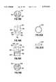
- FIGS. 18A-B and 19A-BA linkage member 311 for use with the flexible shaft portion 310 of the present invention is shown in FIGS. 18A-B and 19A-B.
- FIG. 18Aillustrates a side view of the linkage member 311 from one perspective
- FIG. 19Aillustrates an alternate side view of the same linkage member 311 having been longitudinally rotated 90 degrees about the axis 312 from the position shown in FIG. 18A.
- the linkage member 311being generally cylindrical in shape, is formed with a body segment 315, a male end 316, and an opposing female end 317 adapted to engage a male end of an adjacent linkage member 311. The male end 316, when viewed from the perspective of FIG.
- Tongue 318projects from the body segment 315 and includes constriction 319 and terminates in a cylindroidal lip 320.
- the lip 320when viewed from the perspective of FIG. 19A, is a cylindroidal member extending substantially across the entire diameter of the body segment 315.
- the female end 317includes a channel 321 defining a second plane that is also parallel to the longitudinal bore 324.
- Channel 321designed to receive the tongue 318, sits partially within the body segment 315. That part of channel 321 sitting within the body segment 315 preferably conforms to the lip 320 of tongue 318, and is provided with somewhat in excess of 180 degrees of arc so as to retain the lip 320 therein. That part of channel 321 which conforms to the constriction 319, in contrast, is characterized by walls 322 extending from the body segment 315. Walls 322, each having an inner surface 323 which tapers inwardly toward the body segment 315, are preferably sufficiently spaced apart so as to firmly engage the constriction 319.
- the design of the tongue 318 and its complementary channel 321allows the tongue 318 to laterally slide into the channel 321 of an adjacent linkage member 311 in a direction that is substantially perpendicular to the longitudinal bore 324.
- a pair of adjacent links 313thus provides the ability to pivot about two axes 314 that are at 90 degrees (i.e. perpendicular) to one another in a manner of a universal joint, and still permits the axial transfer of torque. Since the present invention allows for such an ability with any three consecutive linkage members 311, the flexible shaft portion 310 may, therefore, conform to a wide range of curvatures along the bore axis 312 while still able to transmit torque to the drive tip 330.
- each of the tongue 318 and channel 321 liesmay be disposed at less than 90 degrees relative to one another.
- more than three consecutive linkage members 311may be needed to achieve the same range of motion available with perpendicularly disposed planes.
- Central bore 324 in each linkage member 311extends longitudinally from the male end 316 to the female end 317.
- the bore 324 of one linkage memberis configured to align with the bore 324 of an adjacent linkage member so as to form a continuous passageway along the flexible shaft portion 310, and through which a guide wire may be received.
- the present inventionincludes a ring 325, as shown in FIGS. 20A-B. Ring 325 may be assembled onto the flexible shaft portion 310 by first placing the ring 325 about the tongue 318 of a linkage member 311.
- the tongue 318is slid laterally into the channel 321 of an adjacent linkage member 311 in a direction that is substantially perpendicular to the longitudinal bore 324.
- the ring 325is next advanced onto the female end 317 of the adjacent linkage member 311, and in particular, about the walls 322.
- the ringthereafter, is preferably attached to the linkage member 311 by laser welding.
- other conventional methods of attachmentwell known in the art may also be used, for example, adhesive bonding or conventional welding.
- the distal end of the flexible shaft portion 310is coupled to the cannulated drive tip 330 via a link 331.
- the cannulation in the drive tip 330is preferably aligned with the passageway formed from the bores 324 in the linkage members 311 of the flexible shaft portion 310 so that a guide wire may be received therethrough.
- the drive tip 330has a head, as described above for the angled driver, shaped for engagement with the proximal end of a screw.
- link 331comprises a male end (not shown) on a terminal linkage member 326 of the flexible shaft portion 310, and a female end (not shown) on the drive tip 330.
- the female end on the drive tip 330has a design similar to the female end 317 of a linkage member 311.
- link 331may substitute, at the terminal linkage member 326, a female end 317 for the male end, and on the drive tip 330, a male end for the previously provided female end, or any combination thereof appropriate for the coupling of the flexible shaft portion 310 to the drive tip 330.
- the proximal end of the flexible shaft portion 310is coupled to a distal portion 342 of handle 340.
- the handle 340is substantially similar in configuration to the above-described handles, including the provision for the optional locking screw 230 in FIG. 12.
- the handle 340may also include a tunnel along the longitudinal axis 312 that is aligned with the passageway formed by the longitudinal bore 324 in each linkage member 311 of the flexible shaft portion 310. In this way, the guide wire extending up the drive tip 330 and through the flexible shaft portion 310 may also extend out through the handle 340.
- the handle 340as can be seen in FIG.
- the stiff shaft portion 350capable of transmitting rotation from the handle 340 to the flexible shaft portion 310, is cannulated to permit a guide wire extending through the flexible shaft portion 310 to extend out through the handle 340.
- the stiff shaft portion 350is coupled to the flexible shaft portion 310 via a link 351.
- Link 351preferably includes, on the stiff shaft portion 350, a male end 353 which is substantially similar to the male end 316 of a linkage member 311, and a female end (not shown) on an initial linkage member 327 of the flexible shaft portion 310 for receiving the male end 353.
- link 351may substitute, at the initial linkage member 327, a male end for the female end, and on the stiff shaft portion 350, a female end for the previously provided male end 353, or any combination thereof appropriate for coupling the stiff shaft portion 350 to the flexible shaft portion 310.
- the flexible shaft portion 310, the drive tip 330, and the stiff shaft portion 350must contact not only surrounding tissues, but must also be able to transmit torque from the handle 340. Accordingly, it is preferable that these components be made from a biocompatible yet strong material, for example stainless steel or molded plastic. Moreover, to protect the surrounding tissues from the being damaged between adjacent linkage members 311, the flexible shaft portion 310 is provided with a flexible sheath 352 disposed about the entire series of linkage members 311 (see FIGS. 15-16). If it is desired, the flexible sheath 352 may also be made to extend over the entire stiff shaft portion 350.
- the surgical screwdrivers described hereinare useful for arthroscopic ligament reconstruction procedures of the knee and of other joints in the human body.
- the kneeis an example of a moveable joint that sustains injury to connective tissue with relative frequency.
- the surgical screwdriversare described herein as applicable to methods of anterior cruciate ligament reconstruction, the surgical screwdriver according to the present invention can also be used in reconstructing posterior ligaments of the knee.
- Other jointsalso rely on ligaments to maintain function. In all joints, ligaments play an important role in holding the different bones of the joints in alignment.
- FIG. 3A method of least invasive, or arthroscopic, anterior cruciate ligament reconstruction according to the present invention is shown in FIG. 3.
- An incision of minimal sizeis made medial to the tibial tubercle and distal to the joint line to harvest a portion of the patellar tendon which will serve as a graft ligament. Subsequently, this incision can be utilized as the portal 142 for inserting surgical instruments to fix one end of the graft ligament in the femoral bone tunnel as described below, and may also be used for access to the region of the cruciate ligament attachment sites to help determine proper placement of the tibial and femoral bone tunnels, with the knee being visualized with an arthroscope.
- Tibial bone tunnel 128 and femoral bone tunnel 130are formed respectively in the tibia and femur.
- the femoral bone tunnelis formed by instruments inserted in a cephalad direction through the tibial bone tunnel.
- the femoral bone tunnel 130is formed as an open-ended longitudinally straight, cylindrical tunnel extending from an opening 132 on the femoral condyle at the attachment site of the anterior cruciate ligament on the femur to an opening 134 on the lateral femoral cortex with (in one embodiment of the method) soft tissue covering the lateral femoral cortex remaining intact.
- the central longitudinal axis of the femoral bone tunnelis therefore substantially offset from the portal 142.
- a ligament 136such as a prosthetic ligament or the graft ligament harvested as previously described, having bone blocks 138 or other suitable terminus at its ends, is inserted initially through the tibial bone tunnel 128 and into the femoral bone tunnel 130 via a puncture wound.
- the puncture woundis in line with opening 134 on the lateral femoral cortex and forward proximally and laterally on the patient's thigh.
- a rigid pushing rodmay be used to help push the graft through the tibial tunnel and into the femoral tunnel.
- the ligament 136is then positioned so as to extend across the knee joint with a bone block 138 or other terminus positioned in each of the bone tunnels 128 and 130.
- a guide wireis inserted through the portal 142 into the femoral tunnel alongside the ligament 136.
- the guide wireis used to guide a bone screw positioned on a driver to the bone block at the end of the graft ligament for the purposes of securing the ligament with the screw.
- the guide wire 72is made from a material such as a nickel-titanium alloy wire and is typically on the order of 14 inches (36 cm) in length. It is inserted into the tibial bone tunnel 128 and through the femoral tunnel 130, with the guide wire 72 exiting the knee through the soft tissue adjacent the lateral femoral cortex. Alternatively, the guide wire 72 can be inserted through the opening 134 on the lateral femoral cortex via the puncture wound described previously.
- the guide wire 72is disposed parallel with the bone block 138 and the wall 140 and, therefore, parallel with the central longitudinal axis of the femoral bone tunnel. If the guide wire is inserted first through the puncture wound, it is advanced until an end of the guide wire 72 is visible at the knee joint. The visible end of the guide wire is grasped and disposed externally of the knee, creating a substantial bend in the guide wire 72, as shown in FIG. 3, using an instrument which is inserted through an anteromedial or anterolateral portal. The bend in the guide wire is due to the fact that the portal 142 is substantially offset from, and not aligned with, the central longitudinal axis of the femoral bone tunnel 130.
- a bone screw 144 having a cannula 145, in the form of a central, coaxial, longitudinal passage therein,is mounted on the end of the guide wire 72 externally of the knee, the cannula having a diameter slightly larger than the diameter of the guide wire 72.
- the end of the guide wire 72is frictionally secured in the cylindrical passage 62 of the drive tip 52.
- the bone screw 144is moved along the guide wire and mounted on the drive tip 52 by drive recess 143. Since the drive recess is coaxial with the cannula, the drive shaft 14 protrudes from the back end of the bone screw 144 by about 5 mm.
- the angled screwdriver 10is inserted at the knee joint via the portal 142.
- the driveris guided into the femoral bone tunnel 130 through the opening 132 on the femoral condyle by simultaneously turning and pushing the driver with the drive tip 52 oriented upwardly.
- the orientation of the drive tipis indicated by the indicator 127 on the forward handle section facing the surgeon, as shown in FIG. 3A.
- the direction of insertion from the portal 142 to the femoral bone tunnel 130is at a non-zero acute angle with respect to the central longitudinal axis of the femoral bone tunnel because the portal 142 is not aligned with the femoral bone tunnel axis.
- the angled screwdriver 10as guided by the guide wire 172, is moved forward along the femoral bone tunnel 130, with the longitudinal axis of the drive shaft 14 disposed parallel with the longitudinal axis of the femoral bone tunnel; and, concurrently, the guide wire 72 is pushed cephalad in the tunnel and through the puncture wound.
- the rearward handle section 86 of the angled screwdriveris manually rotated relative to the forward handle section 84, while the forward handle section is grasped and held fixed, to rotate the operating shaft 12 relative to the sleeve 18. Consequently, the drive shaft 14 (the driven end), driven by handle 22, drives the screw 144 in a direction that is at a non-zero acute angle with respect to the handle (i.e, the driving end) of the angled screwdriver. Accordingly, the bone screw 144 is driven in a forward direction in the femoral bone tunnel 130 laterally between the bone block 138 and the wall 140 and parallel to the bone block 138 and the wall 140.
- a thread on the screwengages the tunnel wall 140 and the bone block 138 along the length of the bone block to fixate the ligament 136.
- the bone screwis driven externally of the knee from a direction offset from the direction of bone screw insertion and with the knee at an angle of substantially 90° such that the hyperflexion is avoided.
- the bone screw 144is driven an additional 5 mm into the femoral bone tunnel 130 due to the exposed portion of the drive shaft 14 at the back end of the screw, allowing a countersink below the opening 132.
- the angled screwdriver 10is then pulled away from the screw 144 for removal through portal 142, and the guide wire 72 can be removed with the driver 10 or pulled away from the driver 10 for removal via the puncture wound in the soft tissue adjacent the lateral femoral cortex.
- the bone block 138 in the tibial bone tunnel 128is then fixated by inserting a bone screw in the tibial bone tunnel and driving the bone screw parallel to the bone block and a wall of the tibial bone tunnel.
- portal 142can be the same portal utilized for alignment determination in forming the tibial and femoral bone tunnels, and that a single portal can be used throughout the procedure to harvest the patellar tendon graft, to orient the tibial and femoral bone tunnels, to help orient the graft ligament, and to insert the bone screw in the femoral bone tunnel.
- the drive shaft 14 of the surgical screwdrivercan be offset from the handle 22 by the bend 78 or a curve as well as other configurations and that the bend, curve or other configuration can be rigid or flexible.
- the angled surgical screwdriver 10can be used with or without the guide wire 72.
- FIG. 5A related embodiment of the method of arthroscopic, anterior cruciate ligament reconstruction is shown in FIG. 5.
- the femoral bone tunnel 130is formed as a blind, or closed-ended tunnel extending from an opening 132 on the femoral condyle to an end wall 172 such that the femoral bone tunnel does not broach the lateral femoral cortex.
- a graft or prosthetic ligament 136 having bone blocks 138 at its endsis inserted in the tibial bone tunnel 128 via the portal to extend across the knee joint with a bone block 138 disposed in each of the bone tunnels of the femur and the tibia.
- a bone screw 144is mounted on the angled screwdriver 150 externally of the knee.
- the drive tip 52 of the driveris engaged in the drive recess of the screw and the retaining mechanism 152 is received in the cannula of the screw.
- the drive shaft 14protrudes beyond the back end of the screw 144 substantially 5 mm.
- the curve of the distal cylindrical section 158 of the wire 154provides frictional engagement in the cannula of the screw 144.
- the screwis positively held by the retaining mechanism 152 upon the angled driver 150 prior to screw insertion. This arrangement allows manipulation of the screw at the knee joint while avoiding disengagement of the screw from the driver and possible loss of the screw in the knee.
- the angled driver 150 with the screw 144 held thereon by retaining mechanism 152is inserted at the knee joint via an anteromedial or anterolateral portal, such as anteromedial portal 174.
- the driver and screware guided into the femoral bone tunnel 130 through the opening 132 on the femoral condyle.
- the drive tip 52remains pointed upwards as indicated by indicator 127 facing the surgeon.
- the direction of insertion from the portal 174 to the femoral bone tunnel 130is at a non-zero acute angle with respect to the central longitudinal axis of the femoral bone tunnel.
- the angled driver 150is advanced along the femoral bone tunnel 130 in a direction parallel with the bone block 138 and the wall 140, and therefore, parallel with the longitudinal axis of the femoral bone tunnel until the bone screw 144 is positioned laterally between the bone block 138 and a wall 140 of the femoral bone tunnel as shown in FIG. 5.
- the rearward handle section 86 of the angled driver 150is rotated relative to the forward handle section 84 while the forward handle section 86 is held fixed, to drive the bone screw 144 into the femoral bone tunnel 130 as described in connection with FIG. 3, and to fixate the ligament 136.
- the longitudinal axis of the operating shaft 12is angularly disposed with respect to the direction of insertion.
- the screwis inserted an additional 5 mm into the femoral bone tunnel 128 and driven parallel with the bone block 138 in the tibial bone tunnel.
- portal 174can be the same portal as utilized in orienting the tibial and femoral bone tunnels, and a single portal can be used to harvest the patellar tendon graft, to orient the tibial and femoral bone tunnels, and to fixate the ligament in the femoral bone tunnel.
- a guide wirecan be used with the angled driver 150 by being driven into the femur to guide the driver during screw insertion.
- Such a guide wirecan be used with the retaining mechanism 152, or in place of the retaining mechanism 152, or as a retaining mechanism by lengthening the distal cylindrical section 158.
- the inventionalso provides, in a further embodiment, a method of arthroscopic, anterior cruciate ligament reconstruction using the flexible cannulated screwdriver 210 as shown in FIG. 14.
- the femoral tunnelmay be formed as an open-ended tunnel or as a blind, or closed ended tunnel.
- the femoral tunnelmay be drilled through the tibial tunnel with the knee at approximately 50 degrees of flexion.
- the flexible cannulated screwdriver used along a guide wiremay be substituted for the angled driver in above-described methods or the following method may be employed advantageously.
- a graft or prosthetic ligament 136 having bone blocks 138 at its endis inserted in the tibial bone tunnel 128.
- a pushing rodmay be used to push the graft across the knee joint into the femoral tunnel so that one bone block 138 is disposed in each of the bone tunnels of the femur and the tibia.
- the kneeis placed at 90 degrees of flexion for insertion of the screw. With the knee in this position, the ligament advantageously drops back away from the path of the interference screw.
- a guide wire 72is inserted through the anteromedial portal 142 into the femoral tunnel alongside the bone block 138 therein.
- the curved sheath 220may be slid over the guide wire to protect surrounding tissue from the screw threads before the screw is driven into engagement with the bone block and bone tunnel.
- a cannulated interference screw 144is mounted onto the guide wire 72.
- the flexible cannulated screwdriveris then mounted on the guide wire such that the drive tip 246 of the screwdriver engages the screw. The driver and screw are guided into the knee joint along the guide wire through the anteromedial portal.
- the driver and screwcontinue along the wire through the femoral condyle into the femoral bone tunnel.
- the shaft of the driveradvantageously bends along the guide wire from the anteromedial portal into the bone tunnel.
- the screwis driven between the bone block and the wall parallel with the longitudinal axis of the femoral bone tunnel. Rotation of the driver handle is transmitted by the shaft to the screw. Once the screw is satisfactorily secured, the driver is pulled out back along the guide wire. If desired, the locking screw on the driver handle can be tightened upon the guide wire so that the guide wire is removed along with the driver.
- a related embodiment of an angled driver according to the present inventionis shown at the distal end in FIGS. 6 and 7 as item 180, which is similar to the angled driver 150, and includes a drive head housing 20 mounting the drive shaft and a distal end of the operating shaft, the drive shaft including a drive tip 52 having a hexagonal configuration in cross-section for engaging a hexagonal drive recess 143 of an interference bone fixation screw 144.
- Drive head housing 20 of angled driver 180is formed integrally with sleeve 18 and includes a flared section 182 distally joined to the sleeve 18, an intermediate cylindrical section 184 joined to flared section 182 and an angled section 186 joined to intermediate section 184.
- the flared and intermediate sections 182 and 184are axially aligned, while the angled section 186 is angularly offset from the flared and intermediate sections such that a longitudinal axis of the angled section is disposed at an angle, with respect to a longitudinal axis of the flared and intermediate sections, that is substantially the same as the angle that the longitudinal axis of the drive shaft is disposed with the longitudinal axis of the operating shaft.
- the drive tip 52 of the angled driver 180is formed of six facets for engaging the drive recess 143 of the bone screw 144.
- Drive tip 52can have a configuration in cross-section that is substantially constant along the length of the drive tip as shown in FIG. 6, or the drive tip 52 can be tapered or stepped in a distal direction to further facilitate insertion through very small portals and mobility at the knee joint. It includes a cylindrical passage 62 coaxial with the drive shaft as shown in FIG. 7, for securing retaining mechanism 152.
- Retaining mechanism 152includes a wire 154 press fit into passage 62 and having a distal cylindrical section 158 protruding beyond the drive tip 52.
- the distal cylindrical section 158is formed with a thermally set, angled bend along a longitudinal axis of the wire 154, the bend being offset from the longitudinal axis of the drive shaft for being disposed in the cannula 145 of the bone screw 144.
- the bone screwis mounted on drive tip 52 such that the screw will be forced slightly out of axial alignment with the drive tip 52 to produce frictional engagement of the drive tip in the drive recess of the screw to resist disengagement of the screw from the angled driver prior to screw insertion as shown in FIG. 6.
- FIG. 8A further modification of an angled driver according to the present invention is shown in FIG. 8 at 190, in which the bone screw is mounted on drive tip 52 without forcing the screw out of axial alignment with the drive tip.
- angled driver 190is substantially the same as angled driver 180.
- Both angled drivers 180 and 190 and the flexible cannulated screwdrivercan be utilized for insertion of bone screws, in arthroscopic cruciate ligament reconstruction in bone tunnels from directions offset from the direction of screw insertion and from portals not aligned with the bone tunnels as previously described; and, the angled screwdriver 180 can be used with or without a guide wire.
- the screwdrivers described hereinallow bone screws to be inserted in bone tunnels parallel with walls of the bone tunnels and bone blocks in the bone tunnels to obtain maximum thread purchase along the entire length of the bone blocks with the screws being driven from directions offset from the direction of screw insertion.
- Bone screwscan be inserted in femoral bone tunnels directly from anteromedial or anterolateral portals and without accessing the femoral bone tunnels through the tibial bone tunnels.
- bone screwscan be inserted in the femoral bone tunnels with the knee positioned at an angle of substantially 90°.
- the present inventionremoves the undesirable requirement for hyperflexion of the knee in order to insert bone screws.
- the same portalcan be employed to perform procedures preparatory to graft fixation, to orient the tibial and femoral bone tunnels and to insert interference screws in the femoral bone tunnel, thereby eliminating the need for portals in soft tissue adjacent the lateral femoral cortex specifically formed for the purpose of inserting bone screws in the femoral bone tunnel.
- trauma and invasivenessare minimized.
- the surgical screwdriver and its methods of use described above for anterior cruciate ligament reconstruction of the kneecan also be applied to other ligament reconstruction procedures including arthroscopic posterior cruciate ligament reconstruction of the knee.
- the driverprovides a means to insert bone screws in bone tunnels in a direction parallel with walls of the bone tunnels and bone blocks in the bone tunnels to fixate a graft or prosthetic ligament in the anatomic position of the posterior cruciate ligament while introducing the screws through portals not aligned with the direction of screw insertion.
- the flexible cannulated screwdriveradvantageously accommodates a wide range of angles between the portal and the tunnel.
Landscapes
- Health & Medical Sciences (AREA)
- Engineering & Computer Science (AREA)
- Life Sciences & Earth Sciences (AREA)
- Surgery (AREA)
- Orthopedic Medicine & Surgery (AREA)
- Public Health (AREA)
- General Health & Medical Sciences (AREA)
- Mechanical Engineering (AREA)
- Veterinary Medicine (AREA)
- Biomedical Technology (AREA)
- Heart & Thoracic Surgery (AREA)
- Animal Behavior & Ethology (AREA)
- Nuclear Medicine, Radiotherapy & Molecular Imaging (AREA)
- Oral & Maxillofacial Surgery (AREA)
- Medical Informatics (AREA)
- Molecular Biology (AREA)
- Rheumatology (AREA)
- Dentistry (AREA)
- Vascular Medicine (AREA)
- Cardiology (AREA)
- Rehabilitation Therapy (AREA)
- Transplantation (AREA)
- Surgical Instruments (AREA)
Abstract
Description
This application is a continuation-in-part of application Ser. No. 08/340,790, filed Nov. 16, 1994, now U.S. Pat. No. 5,464,407, which is a continuation-in-part of application Ser. No. 07/956,733, filed Oct. 2, 1992 and issued Feb. 21, 1995 as U.S. Pat. No. 5,391,170, which is a continuation-in-part of application Ser. No. 07/806,906, filed Dec. 13, 1991 and issued Nov. 2, 1993 as U.S. Pat. No. 5,257,996, and application Ser. No. 07/839,466, filed Feb. 19, 1992, now U.S. Pat. No. 5,520,693. These related applications are hereby incorporated herein by reference.
The present invention pertains to surgical screwdrivers for inserting bone screws and, more particularly, to surgical screwdrivers for inserting interference bone fixation screws in bone tunnels and to methods of performing arthroscopic cruciate ligament reconstruction of the knee.
Various surgical procedures utilize devices to fixate anatomical tissue for healing. An example of a fixation device is an interference bone fixation screw, commonly referred to throughout the present description as "interference screw", used to fixate ligaments within bone tunnels during cruciate ligament reconstruction of the knee.
A surgical screwdriver is commonly used to insert bone screws. This form of screwdriver has a rotatable drive shaft for rotating the screw, and advancing it along the longitudinal axis of the driver. The driver cooperatively engages with a drive recess, within the interference screw, to help achieve axial alignment of the screw with the drive shaft of the screwdriver.
In cruciate ligament reconstruction, the interference screw is inserted into tandem isometrically positioned bone tunnels formed in the tibia and femur. A prosthetic ligament graft affixed to bone blocks at each end is inserted into the bone tunnel such that the ligament extends across the knee joint in the anatomical position of the cruciate ligament. The bone blocks are fixated within the bone tunnel by interference screws. Each interference screw is inserted in the bone tunnel so as to be disposed laterally between the walls of the bone tunnel and the bone block. Successful cruciate ligament reconstruction depends on the proper insertion of the interference screw along the longitudinal axis of the bone tunnel, parallel to both the tunnel walls and the bone block. Incorrect insertion of the interference screw causes screw divergence, resulting in increased difficulty in advancing the screw in the bone tunnel and reduced contact between the threads on the screw and the bone block. In addition, screw convergence can result in crushing or fracturing of the ligament and dislocation of the bone block, causing deviation of the ligament from an accurate, pre-established isometric position.
Cruciate ligament reconstruction is commonly performed as an open surgical procedure. Incisions on the order of 10 inches in length are utilized to access the knee joint. These relatively long incisions are required to provide room for the surgical screwdriver to approach the tibial and femoral bone tunnels from directions aligned with the longitudinal axes of the bone tunnels and thereby to permit the driver to drive the interference screws effectively in a direction parallel with the bone block and the walls of the bone tunnels.
Open surgery possesses numerous disadvantageous compared to closed surgery or less invasive (arthroscopic) surgery for ligament reconstruction. These disadvantages include possible violation of mechanoreceptors in the knee, desiccation of articular cartilage of the joint, increased tissue trauma resulting from incisions accompanied by increased patient discomfort and delayed post surgical mobility. In addition, hospitalization and rehabilitation times may be prolonged.
Accordingly, it is desirable to develop methods for performing cruciate ligament reconstruction that are less invasive, such as arthroscopic surgical procedures. Narrow portals are made with a puncture or stab wound in tissue adjacent to the knee of sufficient size to permit insertion of surgical instruments at the knee joint with the knee being visualized with an arthroscope. An arthroscope is here defined as any instrument for insertion into the cavity of a joint in order to inspect its contents. An example of an arthroscope is a fiberscope, which uses fiber optics to transmit images from the interior of the joint.
A method of arthroscopic cruciate ligament reconstruction can provide many benefits over open surgery, including reduced tissue trauma, decreased patient discomfort, earlier and aggressive range of motion and weight bearing without loss of fixation, reduced rehabilitation time and elimination of hospitalization because the procedures can be performed on an out-patient basis.
The limitations on maneuverability imposed by arthroscopic cruciate ligament reconstruction and the location of the arthroscopic portals in tissue adjacent to the knee mean that conventional drivers with straight drive shafts, which are used for placing interference screws into bone tunnels through incisions during open surgery, are not suited for this procedure.
Indeed, the anteromedial and anterolateral portals are angularly offset from the longitudinal axis of the femoral bone tunnel and therefore the direction of approach from such portals to the femoral bone tunnel to insert an interference screw is angularly offset also. The femoral bone tunnel opens on the femoral condyle at a site near the attachment site of the cruciate ligament. Longitudinal alignment of the screwdriver with the opening of the femoral bone tunnel on the femoral condyle is difficult using conventional surgical drivers when the approach is made through the arthroscopic portals. This in turn presents difficulties in driving the screw parallel with the longitudinal axis of the femoral bone tunnel and the bone block in the tunnel.
Attempting to force the driver into parallelism with the longitudinal axis of the femoral bone tunnel runs a number of serious risks, including the possible breakage of the shaft of the driver at the knee; disengagement of the interference screws from the driver during manipulation and their contact with adjacent knee structures, followed by loss of the interference screw in the knee; and misalignment of the interference screw between the wall of the femoral bone tunnel and the bone block.
One compromise approach to the problem of location of arthroscopic portals is to introduce additional portals specifically for the purpose of inserting interference screws into the bone tunnel. One approach is to insert the interference screw through openings of the femoral bone tunnels on the lateral femoral cortex via portals placed proximally and laterally on the patients' thigh. This approach precludes the use of blind or closed end femoral bone tunnels. Alternatively, interference screws can be inserted through openings in the femoral condyle after their introduction through the tibial bone tunnels.
Angled drivers have been used in industrial applications as wrenches and screwdrivers, and exemplary of such devices are U.S. Pat. Nos. 4,643,052 to Badiali, 4,620,458 to Schmidek, 3,788,169 to Nakayama, 3,696,694 to Boro, 3,604,486 to Henry, 3,232,151 to Blachowski, 2,042,376 to Balga, 1,428,282 to Glabaznya, 1,398,116 to Root, 1,199,823 to Sadtler, 933,639 to Frink and 877,571 to Larson. In medical applications, angled drivers have been used in power tools such as drills, and U.S. Pat. Nos. 5,041,119 to Frigg et al and 4,947,942 to Lightle et al are illustrative of angled, surgical power drills.
Prior art angled surgical drivers are unsuitable for use in least invasive, or endoscopic, surgical procedures to insert interference screws in bone tunnels directly from portals not aligned parallel with longitudinal axes of the bone tunnels. Moreover, angled surgical drivers in the prior art cannot effectively hold screws captive for insertion into the body through endoscopic size portals.
The present invention provides, in one embodiment, a flexible surgical screwdriver for driving an interference screw into bone so that the screw is securely supported by the driver until insertion has been completed. The flexible surgical driver permits access from an arthroscopic portal not aligned parallel with a longitudinal axis of the bone tunnel to place the interference screw parallel with the walls of the bone tunnel and the bone block while driving the screw from a direction angularly disposed with the tunnel wall.
One embodiment has a flexible shaft, a handle mounted to the flexible shaft for applying rotational force to the shaft, and a drive head mounted on the flexible shaft. The flexible shaft and handle are cannulated according to an embodiment for use with cannulated interference screws. The cannulated screw and driver are guided over a guide wire into position along the bone tunnel wall.
The flexible shaft may be formed by a plurality of linkage members disposed in series. Each linkage member is joined to an adjacent linkage member so as to permit adjacent linkage members to be pivotally movable with respect to one another about a pivot axis while maintaining the ability to transmit torque upon the rotation of the handle.
An alternative embodiment of a screwdriver in accordance with the present invention permitting access from an arthroscopic portal not aligned parallel with a bone tunnel is an angled driver. The drive shaft is mounted on the operating shaft at an angle of approximately 20° with respect to the longitudinal axis of the operating shaft. An indicator on the handle allows orientation of the drive tip to be identified externally of the body, when the drive tip is inserted in the body through portals of minimal size. The angled driver may be used without being cannulated. In this case, a retaining mechanism for holding a cannulated interference screw captive on the drive shaft prior to screw insertion includes a wire having a proximal cylindrical section secured in a passage in the drive tip aligned with the longitudinal axis of the drive shaft and a distal cylindrical section that protrudes beyond the drive tip to be received in the cannula of the interference screw. The distal cylindrical section of the retaining mechanism is formed with a thermally set, slight curve or kink to hold the screw temporarily in place on the drive tip.
The procedure in accordance with a preferred embodiment of the present invention advantageously eliminates the step of penetrating the lateral femoral cortex and permits a countersink of the screw below the opening of the femoral bone tunnel on the femoral condyle. The procedure can be performed with fewer and smaller portals. In fact, the anteromedial and anterolateral portals formed for procedures preparatory to graft fixation can be utilized to directly insert bone screws in femoral bone tunnels. In addition, hyperflexion of the knee in arthroscopic anterior cruciate ligament reconstruction can be eliminated.
The surgical instrument provided in a preferred embodiment of the invention is designed to avoid drive shaft breakage, loss of interference screws at the knee joint, and to enhance screw insertion and driver positioning. In addition, screw divergence is minimized and maximum thread purchase along the length of the bone block is ensured. The embodiment is of unified construction for easy cleaning and sterilization with right and left knee compatibility. The embodiment employs a lightweight, ergonomic handle providing a balanced feel for the surgeon.
These and other features of the present invention may be more readily understood by reference to the following description, taken in conjunction with the accompanying drawings, in which:
FIG. 1 is a broken side view, partly in longitudinal section, of an embodiment of an angled surgical screwdriver according to the present invention, showing an interference screw mounted on the screwdriver;
FIG. 2 is an exploded, broken side view, partly in section, of the distal end of the angled surgical screwdriver of FIG. 1;
FIG. 3 is a front view, partly in section, of the joint of a right knee positioned at substantially 900, showing the angled surgical screwdriver of FIG. 1 approaching an open end femoral bone tunnel via an anterolateral portal;
FIG. 3A is a top view of the angled surgical screwdriver of FIG. 1;
FIG. 4 is a broken side view, partly in section, of the drive shaft of a related embodiment of an angled surgical screwdriver according to the present invention, showing a retaining mechanism on the drive shaft and an end of a forming tool for mounting the retaining mechanism on the drive shaft;
FIG. 5 is a front view, partly in section, of the knee, joint of a right knee positioned at substantially 90o, showing the angled surgical screwdriver of FIG. 4 inserting a bone screw in a closed end femoral bone tunnel via an anteromedial portal;
FIG. 6 is a broken side view of the distal end of a further embodiment of an angled surgical screwdriver according to the present invention;
FIG. 7 is a broken side view, partly in section, of the drive shaft for the angled surgical screwdriver of FIG. 6;
FIG. 8 is a broken side view of the distal end of another embodiment of an angled surgical screwdriver according to the present invention;
FIG. 9 is an isometric view of a cannulated flexible screwdriver of the present invention;
FIG. 10 is an isometric view of a curved cannula for use with the screwdriver of FIG. 9;
FIG. 11 is a broken view of an alternate embodiment of the curved cannula of FIG. 10;
FIG. 12 is a plan view of a further embodiment of a cannulated flexible screwdriver of the present invention;
FIG. 13 is an exploded view of the screwdriver of FIG. 12;
FIG. 14 is a front view, partly in section, of the joint of a knee, showing the screwdriver of FIG. 9 approaching a femoral tunnel via a curved cannula inserted through an anterolateral portal;
FIG. 15 is an isometric view of a cannulated flexible screwdriver in accordance with another embodiment of the present invention;
FIG. 16 shows the screwdriver of FIG. 15 in a flexed position;
FIG. 17 is an isometric view of a flexible shaft portion for use with the screwdriver of FIG. 15;
FIG. 18A is a side view of a linkage member of the flexible shaft portion shown in FIG. 17;
FIG. 18B is a top end view of the linkage member shown in FIG. 18A;
FIG. 19A is an alternate side view of the linkage member shown in FIG. 18A having been rotated by 90 degrees about its longitudinal bore;
FIG. 19B is a bottom end view of the linkage member shown in FIG. 19A;
FIGS. 20A-B show a ring for use with the flexible shaft portion shown in FIG. 17.
An angledsurgical screwdriver 10 according to an embodiment of the present invention is illustrated in FIG. 1, and includes anelongate operating shaft 12 with adistal end 16 coupled to adrive shaft 14 and aproximal end 24 on which is mounted a movable portion ofhandle 22. Concentrically disposed around the operatingshaft 12 is asleeve 18, having adistal end 42, on which is mounted adrive head housing 20 and aproximal end 44 secured in a fixed portion ofhandle 22. Turning the movable portion ofhandle 22 with respect to the fixed portion thereof causes rotation of thedrive shaft 14, which is disposed at an angle of approximately 20° from the axis of rotation ofhandle 22. The operation of thescrewdriver 12 is described in further detail below.
The operatingshaft 12 is preferably made of stainless steel with a cylindrical body terminating, at thedistal end 16, at adistal end wall 30. Fitted concentrically around thedistal end 16 is acylindrical barrel 28, detail of which is shown in FIG. 2. Asocket 32 is formed distally inbarrel 28 in axial alignment with a longitudinal axis of the operatingshaft 12 and, therefore, the longitudinal axis of thedriver 10, as shown in FIGS. 1 and 2.
Aball mechanism 56 includes acylindrical flange 64 joined tocylindrical neck 54, acurved neck 66 extending proximally fromflange 64, and aball 68 mounted oncurved neck 66. Thecylindrical flange 64 has an outer diameter that is substantially the same as the outer diameter of thecylindrical body 48 and larger than the diameter of thecylindrical neck 54, such that an annular recess is defined concentrically around thecylindrical neck 54 laterally between thebody 48 and theflange 64 of thedrive shaft 14. Theball 68 has a hexagonal configuration in cross-section, being formed of six curved surfaces extending proximally fromcurved neck 66 to anend surface 70.Ball 68 is configured to be received insocket 32 of the operatingshaft 12 with the longitudinal axis of thedrive shaft 14 disposed at an acute angle of approximately 20° with respect to the longitudinal axis of the operatingshaft 12. Engagement of theball 68 in thesocket 32 causes rotation of thedrive shaft 14 in response to rotation of the operatingshaft 12.
Driveshaft 14 is preferably made of stainless steel and, as shown in FIGS. 1 and 2, includes acylindrical body 48, adrive tip 52, and theball mechanism 56, in axial alignment. Thecylindrical body 48 is joined to thedrive tip 52 at the distal end of a shoulder 50 tapered in a distal direction, the proximal end of shoulder 50 joining aneck 54, which in turn proximally joins thecylindrical body 48 to theball mechanism 56. Thedrive tip 52 has a distally taperedshoulder 58 terminating distally at an annular,peripheral lip 60, and acylindrical passage 62 is formed in thedrive tip 52 to extend proximally, longitudinally fromlip 60 in axial alignment with the longitudinal axis of the drive shaft.
One purpose of thedrive tip 52 is to frictionally secure the end of a length ofguide wire 72, such as a nickel-titanium alloy wire, as will be explained below, as shown in FIG. 1. Another purpose of the drive tip is to frictionally engage a screw. Thedrive tip 52 has an external configuration to frictionally engage a drive recess 143 of an interferencebone fixation screw 144. Thedrive tip 52 can have various cross-sectional configurations--for example, multi-lobed or pronged, or hexagonal--corresponding to the configuration of the drive recess 143 of thefixation screw 144, so the screw will be rotated in bone with rotation of thedrive shaft 14.
Thecylindrical body 48 may be formed with the same cross-sectional configuration as, but slightly greater dimensions than, thedrive tip 52, so as to frictionally engage the drive recess 143 of thescrew 144, when, as shown in FIG. 1, thedrive tip 52 is inserted deeply enough into thescrew 144 to cause thebody 48 portion to enter the drive recess 143.
In a preferred embodiment, thedrive shaft 14 is prevented from being inserted into the drive recess 143 so far that thedrive head housing 20 contacts the proximal end ofscrew 144. In this embodiment, the back end of thescrew 144 is spaced distally from thedrive head housing 20 to allow a portion (approximately 5 mm in one preferred embodiment) of thedrive shaft 14 beyond thedrive head housing 20 to be exposed. The exposed portion permits thescrew 144 to be countersunk into a bone tunnel by an approximate additional amount equal to the length of the exposed portion.
The back end of the screw can be made to terminate distally of thedrive head housing 20 in various ways. These include (a) making the distance from thelip 60 to thedrive head housing 20 less than the length of the drive recess 143; or (b) forming thedrive shaft 14 with external configurations or diametric dimensions limiting the distance that thedrive shaft 14 can be inserted in the drive recess 143; or (c) providing a retaining mechanism on thedrive shaft 14 that limits the distance that thedrive shaft 14 can be inserted in the drive recess 143 as will be explained further below.
Drivehead housing 20 is preferably made of stainless steel and includes acylindrical section 74 and a distallytapered nose section 76 joined to thecylindrical section 74 at abend 78, thenose section 76 extending angularly, distally from thecylindrical section 74. The wall of thecylindrical section 74 has a thickness that is substantially constant along the length of the cylindrical section with an inner diameter sized to closely receive the outer diameters of thecylindrical barrel 28 and thesleeve 18. The wall of thenose section 76 has a thickness that is greater than the wall thickness of thecylindrical section 74 atbend 78 to define aninternal shoulder 80 serving as a stop forcylindrical barrel 28 when operatingshaft 12 is disposed within thecylindrical section 74. The wall thickness of thenose section 76 tapers in a distal direction such that an internal, cylindrical passage of substantially constant cross-section is defined along the length of the nose section. The cylindrical passage of thenose section 76 is disposed at an angle with respect to the longitudinal axis of the cylindrical passage of thecylindrical section 74 that the angle of thedrive shaft 14 with respect to the operatingshaft 12.
A C-shapedclip 82 is mounted (by welding, for example, or simply by appropriate dimensions) in an annular slot in thenose section 76 and is received in the annular recess aroundneck 54 to prevent axial movement of thedrive shaft 14 while allowing the drive shaft to rotate within thehousing 20.
In a related embodiment of the angled surgical screwdriver shown in FIGS. 4, 6 and 8, theangled driver 150 is substantially the same as theangled driver 10 of FIG. 1, except that aretaining mechanism 152, for holding an interference bone fixation screw captive on the driver prior to insertion of the screw, is mounted ondrive shaft 14.Retaining mechanism 152 includes a length of wire 154 (identified in FIGS. 6 and 8), such as a nickel-titanium alloy wire, having a proximal cylindrical section 156, which is joined toneck 160 at a shoulder 162, and a distalcylindrical section 158 joined to the proximal cylindrical section 156 byneck 160.
Theneck 160 has an outer diameter that is smaller than the outer diameters of the proximal and distal cylindrical sections, which in turn are slightly smaller than the diameter of the cannula 145 in the interferencebone fixation screw 144. The outer diameter of the proximal cylindrical section 156 is sufficient to be received in thepassage 62 in thedrive tip 52 ofdrive head 14. The distalcylindrical section 158 is formed with a thermally set, slight radius curve along its length. The length of thewire 154 that protrudes beyond thedrive tip 52 when the proximal cylindrical section 156 is received therein is selected to allow the curved distalcylindrical section 158 to be disposed in the cannula 145 of thescrew 144 and to provide frictional engagement with the walls forming the cannula 145 when the screw is placed upon thedrive shaft 14, such as shown in FIG. 8.
Thewire 154 is mounted on thedrive shaft 14 by press fitting the proximal cylindrical section 156 in thepassage 62 of thedrive tip 52 in a manner such that theneck 160 is aligned withedge 60 ofdrive tip 52. In some instances, depending on the material from which tip 152 is made, a press fit is sufficient and there is no need forneck 160 or shoulder 162. In other instances, when a neck and shoulder structure is used, a formingtool 164 is useful.
Formingtool 164 has alongitudinal cavity 166 terminating at arecess 168 tapered in the distal direction. In use, the formingtool 164 is moved along thewire 154 in the direction of thedrive shaft 14 until theend wall 170 abuts thedrive tip 52. In that position, the forming tool is urged against thetip 52, and the forming tool's taperedrecess 168 forces thelip 60 to gripneck 160, and this grip, along with theshoulder 160, prevent thewire 154 from falling out of thedrive shaft 14.
Theretaining mechanism 152 may be used on drivers having drive tips axially aligned with longitudinal axes of the drivers to hold a screw upon the drivers prior to screw insertion, and theretaining mechanism 152 is not limited to use with angled drivers. Theretaining mechanism 152 may also be constructed in such a way that the fit of thewire 154 in the cannula 145 ofscrew 144 limits the depth that thedrive shaft 14 may be inserted into the drive recess 143.
Theproximal end 24 of the operatingshaft 12 extends beyond theproximal end 44 of thesleeve 18. Acylindrical aperture 46 to receive a set screw is formed in the proximal extension and is disposed radially with respect to the longitudinal axis of the operatingshaft 12.
Thesleeve 18 has an outer diameter substantially the same as the outer diameter ofbarrel 28 at the distal end of the sleeve to form a smooth external profile with the barrel. Thesleeve 18 has an inner diameter sized to closely receive the outer diameter of the operatingshaft 12 while still permitting the operatingshaft 12 to rotate relative to thesleeve 18.
Forward handlesection 84 is of hollow construction and has acylindrical wall 88 defining an open proximal end and atapered wall 90 distally joined tocylindrical wall 88 and terminating at afront wall 92.Wall 90 is tapered in a distal direction and is flared adjacent tofront wall 92 to define an external profile that facilitates grasping during use.Concentric ribs 94 are provided along an external surface of theforward handle section 84 to facilitate gripping during use. Acylindrical bushing 96 is disposed in the open proximal end of theforward handle section 84. Thebushing 96 has an annular,peripheral flange 98 at a forward face thereof abutting an internalannular shoulder 100 of thecylindrical wall 88. A central opening is formed inbushing 96 for securing theproximal end 44 of thesleeve 18 therein.Bushing 96 andsleeve 18 are preferably welded to theforward handle section 84 to form a sealed, water-tight cavity.
Theforward handle section 84 is assembled with therearward handle section 86, in such a way that thecylindrical wall 88 within the distal end of theforward handle section 84 abuts thecylindrical wall 102 of therearward handle section 86 at ajunction 124. Aring 126, preferably made of stainless steel, is disposed concentrically around thehandle 22 to extend over thejunction 124, thering 126 being mounted in grooves in the forward and rearward handle sections, while creating a stainless to stainless bearing surface that minimizes friction between the relatively movable components of thehandle 22, to provide a good tactile response during use. Athrust washer 122 is disposed concentrically withinrim 110 abutting the forward face of thebushing 106 such that therearward handle section 86 can be assembled with theforward handle section 84 with thethrust washer 122 abutting a rearward face ofbushing 96 andrim 110 extending along thecylindrical wall 88 within the distal end of theforward handle section 84.
As shown in FIG. 3A,indicator 127, here an arrow, is provided along an external surface of theforward handle section 84 to indicate, from a position external of the body, the orientation of thedrive tip 52 when inserted in the body through an endoscopic portal. Theindicator 127 is disposed on the same side ofhandle 22 as thedrive tip 52 and is aligned with thedrive tip 52 and the longitudinal axis of thesurgical screwdriver 10 such that, with theindicator 127 facing a surgeon, thedrive tip 52 will be oriented in a direction angularly upward relative to the longitudinal axis of the surgical screwdriver. Theindicator 127 may utilize a wide range of suitable symbols, including arrows, lines or dots, and may be formed on the handle in diverse ways, such as by laser etching, engraving, or chemical deposition. Where formed as an indentation in the surface of theforward handle section 84, theindicator 127 can provide a tactile, as well as a visual, indication of the position of thedrive tip 52.
The angled driver of the embodiment described herein includes numerous design features that facilitate its use in arthroscopic anterior cruciate ligament reconstruction. At the drive tip, the walls of thecylindrical section 74 and thenose section 76 have a minimal thickness to reduce the overall outer diameter of the angledsurgical screwdriver 10 in the area ofbend 78, and the distance that the angledsurgical screwdriver 20 protrudes distally beyondbend 78 is minimized to enhance maneuverability of the driver within the close confines of the knee joint and to allow the use of smaller portals in arthroscopic cruciate ligament reconstruction. The minimal diametric dimension and distal taper of the nose section facilitate insertion of the driver in bone tunnels, allowing thedrive shaft 14 to be inserted in bone tunnels up to bend 78.Shoulders 50 and 58 give the drive head 14 a distal taper, facilitating insertion in portals of minimal size and additionally enhance maneuverability at the knee joint. Thedrive shaft 14 protrudes beyond the back end of thebone screw 144 and spaces the bone screw distally from the bend 78 a greater amount, such that the bone screw can be inserted that much further into a bone tunnel with the driver inserted in the bone tunnel up to thebend 78. According to a preferred embodiment, the outer diameter of theangled driver 10 atbend 78 is approximately 0.350 inches (8.9 mm), and the distance that the driver protrudes distally ofbend 78 is approximately 0.710 inches (18.0 mm).
In accordance with the present invention, an angled surgical screwdriver can be achieved by providing a flexible drive shaft. In addition, the capability of guiding the angled screwdriver along a guide wire may be made possible by providing a cannulation through the drive shaft and the handle of the screwdriver. Referring now to FIG. 9, a flexible cannulatedscrewdriver 210 is shown. Aflexible drive shaft 212 may be formed by two or more concentric wire coils. The coils are wound in opposite directions, one being clockwise and another counterclockwise. The coils advantageously leave a tunnel through the center of the shaft through which a guide wire may be inserted. Ahandle 214 is attached to one end of the drive shaft. Thehandle 214 has a longitudinal tunnel orcannula 215 in alignment with the tunnel through theflexible shaft 212. At the distal end of thedrive shaft 212, adrive tip 216 is mounted. Thedrive tip 216 is configured to engage a drive recess or drive protrusion at the rear of a screw. Thedrive tip 216 is cannulated to receive a guide wire that will pass through the shaft and handle of the driver. The spiral coils are advantageously flexible so that the drive shaft can assume a wide range of angles for driving a screw into its desired location. By providing two oppositely wound coils, the screwdriver can be used to transmit rotational movement in either a clockwise or counterclockwise direction. In one rotational direction, one of the coils tightens and rotates the drive head. In the opposite rotational direction, the other spiral coil tightens and rotates the drive head in the opposite rotational direction. If the screwdriver is to be used only for rotation in a single direction, it would be sufficient to use a single spiral coil. Moreover, other materials beside spiral coils may provide the requirements of flexibility and rotational stiffness. For example, the shaft may possibly be formed by a Nickel-titanium alloy tube. Therefore, the use of such other materials and constructions as are well known to those of ordinary skill in the art are included for use within the scope of the present invention of a flexible cannulated surgical screwdriver.
Acurved sheath 220 may be used in conjunction with the guide wire to assist in protecting surrounding tissue from the screw threads. In accordance with a presently preferred embodiment of thecurved sheath 220, an opening orslot 222 is provided at the distal end of the sheath to permit direct visualization of the screwdriver tip as it enters the bone tunnel.
The curved sheath may be modified as shown in FIG. 11 to add asharp flange 224 projecting from the distal end of the curved sheath away from the sheath. Thesharp flange 224 may be dug into a bone portion of the graft so as to hold the graft in place during interference screw fixation.
In accordance with a presently preferred embodiment of the cannulated flexible screwdriver of the invention, reference now is made to FIGS. 12 and 13. Thehandle 214 is designed to give the surgeon enough leverage to apply sufficient torque upon an interference screw. However, care is taken in designing the handle to help avoid application of too much torque. For example, the handle on a driver for bio-absorbable screws is made narrower because such screws cannot withstand as much torque as a stainless steel screw. The presently preferred handle dimensions for driving steel screws are 3/4 inches (2 cm) thick and 11/2 inches (3.8 cm) wide at its widest portion. The choice of dimensions depends upon the type of screw to be used with the driver.
Anoptional locking screw 230 may be provided on the handle for clamping onto the guide wire when it is within the cannula of the driver. This can be helpful in removing the guide wire from the bone tunnel after the interference screw has been properly secured between a bone graft and the bone tunnel wall. After the screwdriving procedure is completed, the lockingscrew 230 may be tightened against the guide wire. Then by pulling on the handle of the screwdriver the guide wire is removed from the bone tunnel. The lockingscrew 230 may be made in several parts for ease of manufacture. A threadedscrew 232 is held within abushing 234. Aknob 236 attaches to the bushing to facilitate manual rotation of the screw.
The screwdriver shaft may also be formed out of several parts. Secured to the handle in the embodiment of FIG. 12 is a stiff cannulatedshaft 242. Thestiff shaft 242 may be made from stainless steel. A counterbore is provided at the distal end of the stiff shaft for accepting theflexible members 244.
Theflexible member 244 of the present embodiment is formed by four concentric coil springs. The concentric coil springs fit closely over one another. This prevents a windup delay in the transmission of torque when the handle is rotated. The concentric coil springs alternate from innermost to outermost between clockwise and counterclockwise helixes. While the clockwise springs tighten and transmit torque, the counterclockwise springs open up. When the driver is rotated in the opposite direction, the counterclockwise springs tighten while the clockwise springs open. If the pitch of the coils is small as in the case for a single wire, the coils might interengage during application of torque. To prevent this, each spring is made with from about three to ten wires. The wires are wound in parallel to form a helix of a single diameter. The reason a plurality of wires is used in each spring is to give the wires of the spring a steeper pitch. With the steeper pitch, during application of torque, adjacent concentric springs will hit against each other with wire strands roughly at right angles to one another. When the inner spring expands, the outer spring contracts. The pitched wires prevent interengagement while permitting torque transmission.
The proximal end of theflexible member 244 is soldered or attached by some other conventional method within the counterbore of thestiff shaft 242. The distal end of theflexible member 244 is soldered or otherwise attached to adrive tip 246. Thedrive tip 246 has a head, as described above for the angled driver, shaped for engagement with the proximal end of a screw. Thedrive tip 246 of the flexible driver is cannulated for fitting over a guide wire.
About the outside of theflexible member 244 is a heat shrinked plastic tube. The plastic tube is preferably made from an autoclavable material.
In a further embodiment of the present invention, flexible cannulated screwdriver may be achieved with a flexible shaft portion having a plurality of linkage members. FIGS. 15 and 16 show a flexible cannulatedscrewdriver 300, including aflexible shaft portion 310 having a plurality oflinkage members 311 being disposed in series. Eachlinkage member 311 is designed to be pivotally movable with respect to an adjacent linkage member so as to permit theflexible shaft portion 310 to conform generally to a curvature along alongitudinal axis 312, or alternatively, to assume a straight configuration. As can be seen in FIG. 15, theflexible shaft portion 310 is attached at its distal end to adrive tip 330 and at its proximal end to ahandle 340. Thedrive tip 330 and handle 340 may be configured in the manner of the handles and drive tips described above. Thus, thehandle 340, for example, may be provided with a lockingscrew 230 as in FIG. 12. In accordance with one embodiment of the present invention, thedrive tip 330 and theflexible shaft portion 310 are cannulated so that a guide wire may extend up through thedrive tip 330 and into theflexible shaft portion 310 when thescrewdriver 300 is being used to secure an interference screw between a bone graft and a bone tunnel wall.
Referring now to FIG. 17, eachlinkage member 311 is joined to an adjacent linkage member via alink 313 so that eachlinkage member 311 may pivot about anaxis 314. Thepivot axis 314 for eachlinkage member 311 is transverse to a longitudinal bore 324 (shown in FIGS. 18A, 18B, 19A, and 19B). However, as can be seen in FIG. 17, eachpivot axis 314 also is disposed at an angle (preferably 90 degrees) with respect to the pivot axis of anadjacent linkage member 311. By providingadjacent linkage members 311 withpivot axes 314 that are perpendicular with respect to one another, theflexible shaft portion 310 can be made to conform to a desired curve while maintaining the ability to transmit torque upon rotation of thehandle 340 so as to rotate thedrive tip 330 in either a clockwise or a counterclockwise direction.
Alinkage member 311 for use with theflexible shaft portion 310 of the present invention is shown in FIGS. 18A-B and 19A-B. It should be noted that whereas FIG. 18A illustrates a side view of thelinkage member 311 from one perspective, FIG. 19A illustrates an alternate side view of thesame linkage member 311 having been longitudinally rotated 90 degrees about theaxis 312 from the position shown in FIG. 18A. Thelinkage member 311, being generally cylindrical in shape, is formed with abody segment 315, amale end 316, and an opposingfemale end 317 adapted to engage a male end of anadjacent linkage member 311. Themale end 316, when viewed from the perspective of FIG. 18A, comprises atongue 318 lying generally in a first plane parallel to thelongitudinal bore 324.Tongue 318 projects from thebody segment 315 and includesconstriction 319 and terminates in acylindroidal lip 320. Thelip 320, when viewed from the perspective of FIG. 19A, is a cylindroidal member extending substantially across the entire diameter of thebody segment 315.
With particular reference to FIG. 19A, thefemale end 317 includes achannel 321 defining a second plane that is also parallel to thelongitudinal bore 324.Channel 321, designed to receive thetongue 318, sits partially within thebody segment 315. That part ofchannel 321 sitting within thebody segment 315 preferably conforms to thelip 320 oftongue 318, and is provided with somewhat in excess of 180 degrees of arc so as to retain thelip 320 therein. That part ofchannel 321 which conforms to theconstriction 319, in contrast, is characterized bywalls 322 extending from thebody segment 315.Walls 322, each having an inner surface 323 which tapers inwardly toward thebody segment 315, are preferably sufficiently spaced apart so as to firmly engage theconstriction 319. The design of thetongue 318 and itscomplementary channel 321 allows thetongue 318 to laterally slide into thechannel 321 of anadjacent linkage member 311 in a direction that is substantially perpendicular to thelongitudinal bore 324.
It will be appreciated that although parallel to thelongitudinal bore 324, the first plane in whichtongue 318 lies, and the second plane in which channel 321 lies are perpendicular relative to one another (FIGS. 18B and 19B). A pair ofadjacent links 313 thus provides the ability to pivot about twoaxes 314 that are at 90 degrees (i.e. perpendicular) to one another in a manner of a universal joint, and still permits the axial transfer of torque. Since the present invention allows for such an ability with any threeconsecutive linkage members 311, theflexible shaft portion 310 may, therefore, conform to a wide range of curvatures along thebore axis 312 while still able to transmit torque to thedrive tip 330. Alternatively, the plane in which each of thetongue 318 andchannel 321 lies may be disposed at less than 90 degrees relative to one another. When this is the case, more than threeconsecutive linkage members 311 may be needed to achieve the same range of motion available with perpendicularly disposed planes.
Central bore 324 in eachlinkage member 311 extends longitudinally from themale end 316 to thefemale end 317. When a plurality oflinkage members 311 are joined in series, thebore 324 of one linkage member is configured to align with thebore 324 of an adjacent linkage member so as to form a continuous passageway along theflexible shaft portion 310, and through which a guide wire may be received. To ensure that the coupling betweenadjacent linkage members 311 may further be sufficiently secured, the present invention includes aring 325, as shown in FIGS. 20A-B. Ring 325 may be assembled onto theflexible shaft portion 310 by first placing thering 325 about thetongue 318 of alinkage member 311. Subsequently, thetongue 318 is slid laterally into thechannel 321 of anadjacent linkage member 311 in a direction that is substantially perpendicular to thelongitudinal bore 324. Thering 325 is next advanced onto thefemale end 317 of theadjacent linkage member 311, and in particular, about thewalls 322. The ring, thereafter, is preferably attached to thelinkage member 311 by laser welding. However, other conventional methods of attachment well known in the art may also be used, for example, adhesive bonding or conventional welding. By providing aring 325 about thefemale end 317 of alinkage member 311, in the presence of a lateral force, thetongue 318 is precluded from laterally sliding from thechannel 321.
The distal end of theflexible shaft portion 310, as may be seen in FIG. 16, is coupled to the cannulateddrive tip 330 via alink 331. The cannulation in thedrive tip 330 is preferably aligned with the passageway formed from thebores 324 in thelinkage members 311 of theflexible shaft portion 310 so that a guide wire may be received therethrough. Thedrive tip 330 has a head, as described above for the angled driver, shaped for engagement with the proximal end of a screw. In the preferred embodiment of the invention, link 331 comprises a male end (not shown) on aterminal linkage member 326 of theflexible shaft portion 310, and a female end (not shown) on thedrive tip 330. The female end on thedrive tip 330 has a design similar to thefemale end 317 of alinkage member 311. In an alternative embodiment, link 331 may substitute, at theterminal linkage member 326, afemale end 317 for the male end, and on thedrive tip 330, a male end for the previously provided female end, or any combination thereof appropriate for the coupling of theflexible shaft portion 310 to thedrive tip 330.
The proximal end of theflexible shaft portion 310, with reference still being made to FIG. 16, is coupled to adistal portion 342 ofhandle 340. Thehandle 340, as previously indicated, is substantially similar in configuration to the above-described handles, including the provision for theoptional locking screw 230 in FIG. 12. Thehandle 340 may also include a tunnel along thelongitudinal axis 312 that is aligned with the passageway formed by thelongitudinal bore 324 in eachlinkage member 311 of theflexible shaft portion 310. In this way, the guide wire extending up thedrive tip 330 and through theflexible shaft portion 310 may also extend out through thehandle 340. In accordance with one embodiment of the present invention, thehandle 340, as can be seen in FIG. 16, further comprises astiff shaft portion 350 disposed between thedistal portion 342 ofhandle 340 and theflexible shaft portion 310. Thestiff shaft portion 350, capable of transmitting rotation from thehandle 340 to theflexible shaft portion 310, is cannulated to permit a guide wire extending through theflexible shaft portion 310 to extend out through thehandle 340.
Thestiff shaft portion 350 is coupled to theflexible shaft portion 310 via alink 351.Link 351 preferably includes, on thestiff shaft portion 350, amale end 353 which is substantially similar to themale end 316 of alinkage member 311, and a female end (not shown) on an initial linkage member 327 of theflexible shaft portion 310 for receiving themale end 353. As withlink 331, link 351 may substitute, at the initial linkage member 327, a male end for the female end, and on thestiff shaft portion 350, a female end for the previously providedmale end 353, or any combination thereof appropriate for coupling thestiff shaft portion 350 to theflexible shaft portion 310.
It will be appreciated that in use theflexible shaft portion 310, thedrive tip 330, and thestiff shaft portion 350 must contact not only surrounding tissues, but must also be able to transmit torque from thehandle 340. Accordingly, it is preferable that these components be made from a biocompatible yet strong material, for example stainless steel or molded plastic. Moreover, to protect the surrounding tissues from the being damaged betweenadjacent linkage members 311, theflexible shaft portion 310 is provided with aflexible sheath 352 disposed about the entire series of linkage members 311 (see FIGS. 15-16). If it is desired, theflexible sheath 352 may also be made to extend over the entirestiff shaft portion 350.
The surgical screwdrivers described herein are useful for arthroscopic ligament reconstruction procedures of the knee and of other joints in the human body. The knee is an example of a moveable joint that sustains injury to connective tissue with relative frequency. Although the surgical screwdrivers are described herein as applicable to methods of anterior cruciate ligament reconstruction, the surgical screwdriver according to the present invention can also be used in reconstructing posterior ligaments of the knee. Other joints also rely on ligaments to maintain function. In all joints, ligaments play an important role in holding the different bones of the joints in alignment.
A method of least invasive, or arthroscopic, anterior cruciate ligament reconstruction according to the present invention is shown in FIG. 3. An incision of minimal size is made medial to the tibial tubercle and distal to the joint line to harvest a portion of the patellar tendon which will serve as a graft ligament. Subsequently, this incision can be utilized as the portal 142 for inserting surgical instruments to fix one end of the graft ligament in the femoral bone tunnel as described below, and may also be used for access to the region of the cruciate ligament attachment sites to help determine proper placement of the tibial and femoral bone tunnels, with the knee being visualized with an arthroscope.
Aligament 136, such as a prosthetic ligament or the graft ligament harvested as previously described, having bone blocks 138 or other suitable terminus at its ends, is inserted initially through thetibial bone tunnel 128 and into thefemoral bone tunnel 130 via a puncture wound. (The puncture wound is in line withopening 134 on the lateral femoral cortex and forward proximally and laterally on the patient's thigh.) A rigid pushing rod may be used to help push the graft through the tibial tunnel and into the femoral tunnel. Theligament 136 is then positioned so as to extend across the knee joint with abone block 138 or other terminus positioned in each of thebone tunnels ligament 136. The guide wire is used to guide a bone screw positioned on a driver to the bone block at the end of the graft ligament for the purposes of securing the ligament with the screw. Theguide wire 72 is made from a material such as a nickel-titanium alloy wire and is typically on the order of 14 inches (36 cm) in length. It is inserted into thetibial bone tunnel 128 and through thefemoral tunnel 130, with theguide wire 72 exiting the knee through the soft tissue adjacent the lateral femoral cortex. Alternatively, theguide wire 72 can be inserted through theopening 134 on the lateral femoral cortex via the puncture wound described previously. Theguide wire 72 is disposed parallel with thebone block 138 and thewall 140 and, therefore, parallel with the central longitudinal axis of the femoral bone tunnel. If the guide wire is inserted first through the puncture wound, it is advanced until an end of theguide wire 72 is visible at the knee joint. The visible end of the guide wire is grasped and disposed externally of the knee, creating a substantial bend in theguide wire 72, as shown in FIG. 3, using an instrument which is inserted through an anteromedial or anterolateral portal. The bend in the guide wire is due to the fact that the portal 142 is substantially offset from, and not aligned with, the central longitudinal axis of thefemoral bone tunnel 130. Abone screw 144 having a cannula 145, in the form of a central, coaxial, longitudinal passage therein, is mounted on the end of theguide wire 72 externally of the knee, the cannula having a diameter slightly larger than the diameter of theguide wire 72. The end of theguide wire 72 is frictionally secured in thecylindrical passage 62 of thedrive tip 52. Thebone screw 144 is moved along the guide wire and mounted on thedrive tip 52 by drive recess 143. Since the drive recess is coaxial with the cannula, thedrive shaft 14 protrudes from the back end of thebone screw 144 by about 5 mm.
With the knee at an angle of substantially 90°, theangled screwdriver 10 is inserted at the knee joint via the portal 142. The driver is guided into thefemoral bone tunnel 130 through theopening 132 on the femoral condyle by simultaneously turning and pushing the driver with thedrive tip 52 oriented upwardly. The orientation of the drive tip is indicated by theindicator 127 on the forward handle section facing the surgeon, as shown in FIG. 3A. The direction of insertion from the portal 142 to thefemoral bone tunnel 130 is at a non-zero acute angle with respect to the central longitudinal axis of the femoral bone tunnel because the portal 142 is not aligned with the femoral bone tunnel axis. Theangled screwdriver 10, as guided by theguide wire 172, is moved forward along thefemoral bone tunnel 130, with the longitudinal axis of thedrive shaft 14 disposed parallel with the longitudinal axis of the femoral bone tunnel; and, concurrently, theguide wire 72 is pushed cephalad in the tunnel and through the puncture wound.
Once the tip of thebone screw 144 is disposed adjacent thebone block 138, therearward handle section 86 of the angled screwdriver is manually rotated relative to theforward handle section 84, while the forward handle section is grasped and held fixed, to rotate the operatingshaft 12 relative to thesleeve 18. Consequently, the drive shaft 14 (the driven end), driven byhandle 22, drives thescrew 144 in a direction that is at a non-zero acute angle with respect to the handle (i.e, the driving end) of the angled screwdriver. Accordingly, thebone screw 144 is driven in a forward direction in thefemoral bone tunnel 130 laterally between thebone block 138 and thewall 140 and parallel to thebone block 138 and thewall 140. A thread on the screw engages thetunnel wall 140 and thebone block 138 along the length of the bone block to fixate theligament 136. The bone screw is driven externally of the knee from a direction offset from the direction of bone screw insertion and with the knee at an angle of substantially 90° such that the hyperflexion is avoided. Thebone screw 144 is driven an additional 5 mm into thefemoral bone tunnel 130 due to the exposed portion of thedrive shaft 14 at the back end of the screw, allowing a countersink below theopening 132.
Theangled screwdriver 10 is then pulled away from thescrew 144 for removal through portal 142, and theguide wire 72 can be removed with thedriver 10 or pulled away from thedriver 10 for removal via the puncture wound in the soft tissue adjacent the lateral femoral cortex. Thebone block 138 in thetibial bone tunnel 128 is then fixated by inserting a bone screw in the tibial bone tunnel and driving the bone screw parallel to the bone block and a wall of the tibial bone tunnel.
It will be appreciated that portal 142 can be the same portal utilized for alignment determination in forming the tibial and femoral bone tunnels, and that a single portal can be used throughout the procedure to harvest the patellar tendon graft, to orient the tibial and femoral bone tunnels, to help orient the graft ligament, and to insert the bone screw in the femoral bone tunnel.
It will also be appreciated that thedrive shaft 14 of the surgical screwdriver can be offset from thehandle 22 by thebend 78 or a curve as well as other configurations and that the bend, curve or other configuration can be rigid or flexible. The angledsurgical screwdriver 10 can be used with or without theguide wire 72.
A related embodiment of the method of arthroscopic, anterior cruciate ligament reconstruction is shown in FIG. 5. Instead of the femoral bone tunnel being formed as an open-ended tunnel, thefemoral bone tunnel 130 is formed as a blind, or closed-ended tunnel extending from anopening 132 on the femoral condyle to anend wall 172 such that the femoral bone tunnel does not broach the lateral femoral cortex.
A graft orprosthetic ligament 136 having bone blocks 138 at its ends is inserted in thetibial bone tunnel 128 via the portal to extend across the knee joint with abone block 138 disposed in each of the bone tunnels of the femur and the tibia.
Abone screw 144 is mounted on theangled screwdriver 150 externally of the knee. Thedrive tip 52 of the driver is engaged in the drive recess of the screw and theretaining mechanism 152 is received in the cannula of the screw. In this configuration, thedrive shaft 14 protrudes beyond the back end of thescrew 144 substantially 5 mm. The curve of the distalcylindrical section 158 of thewire 154 provides frictional engagement in the cannula of thescrew 144. The screw is positively held by theretaining mechanism 152 upon theangled driver 150 prior to screw insertion. This arrangement allows manipulation of the screw at the knee joint while avoiding disengagement of the screw from the driver and possible loss of the screw in the knee.
With the knee at an angle of substantially 90°, theangled driver 150 with thescrew 144 held thereon by retainingmechanism 152 is inserted at the knee joint via an anteromedial or anterolateral portal, such asanteromedial portal 174. The driver and screw are guided into thefemoral bone tunnel 130 through theopening 132 on the femoral condyle. Thedrive tip 52 remains pointed upwards as indicated byindicator 127 facing the surgeon. The direction of insertion from the portal 174 to thefemoral bone tunnel 130 is at a non-zero acute angle with respect to the central longitudinal axis of the femoral bone tunnel. Theangled driver 150 is advanced along thefemoral bone tunnel 130 in a direction parallel with thebone block 138 and thewall 140, and therefore, parallel with the longitudinal axis of the femoral bone tunnel until thebone screw 144 is positioned laterally between thebone block 138 and awall 140 of the femoral bone tunnel as shown in FIG. 5.
Once the tip of thebone screw 144 is disposed adjacent thebone block 138, therearward handle section 86 of theangled driver 150 is rotated relative to theforward handle section 84 while theforward handle section 86 is held fixed, to drive thebone screw 144 into thefemoral bone tunnel 130 as described in connection with FIG. 3, and to fixate theligament 136. Again the longitudinal axis of the operatingshaft 12 is angularly disposed with respect to the direction of insertion. The screw is inserted an additional 5 mm into thefemoral bone tunnel 128 and driven parallel with thebone block 138 in the tibial bone tunnel.
As in the case of FIG. 3, portal 174 can be the same portal as utilized in orienting the tibial and femoral bone tunnels, and a single portal can be used to harvest the patellar tendon graft, to orient the tibial and femoral bone tunnels, and to fixate the ligament in the femoral bone tunnel.
A guide wire can be used with theangled driver 150 by being driven into the femur to guide the driver during screw insertion. Such a guide wire can be used with theretaining mechanism 152, or in place of theretaining mechanism 152, or as a retaining mechanism by lengthening the distalcylindrical section 158.
As an alternative to the angled driver described above, the invention also provides, in a further embodiment, a method of arthroscopic, anterior cruciate ligament reconstruction using the flexible cannulatedscrewdriver 210 as shown in FIG. 14. For the ease of discussion, reference is now made to only the flexible cannulatedscrewdriver 214 with the understanding that the steps disclosed hereinafter are equally applicable to the flexible cannulatedscrewdriver 300 shown in FIGS. 15-16. The femoral tunnel may be formed as an open-ended tunnel or as a blind, or closed ended tunnel. The femoral tunnel may be drilled through the tibial tunnel with the knee at approximately 50 degrees of flexion. The flexible cannulated screwdriver used along a guide wire may be substituted for the angled driver in above-described methods or the following method may be employed advantageously. A graft orprosthetic ligament 136 having bone blocks 138 at its end is inserted in thetibial bone tunnel 128. A pushing rod may be used to push the graft across the knee joint into the femoral tunnel so that onebone block 138 is disposed in each of the bone tunnels of the femur and the tibia. The knee is placed at 90 degrees of flexion for insertion of the screw. With the knee in this position, the ligament advantageously drops back away from the path of the interference screw. Aguide wire 72 is inserted through the anteromedial portal 142 into the femoral tunnel alongside thebone block 138 therein. If desired, thecurved sheath 220 may be slid over the guide wire to protect surrounding tissue from the screw threads before the screw is driven into engagement with the bone block and bone tunnel. However, with the knee placed at about 90° the sheath is generally not required. A cannulatedinterference screw 144 is mounted onto theguide wire 72. The flexible cannulated screwdriver is then mounted on the guide wire such that thedrive tip 246 of the screwdriver engages the screw. The driver and screw are guided into the knee joint along the guide wire through the anteromedial portal. The driver and screw continue along the wire through the femoral condyle into the femoral bone tunnel. The shaft of the driver advantageously bends along the guide wire from the anteromedial portal into the bone tunnel. The screw is driven between the bone block and the wall parallel with the longitudinal axis of the femoral bone tunnel. Rotation of the driver handle is transmitted by the shaft to the screw. Once the screw is satisfactorily secured, the driver is pulled out back along the guide wire. If desired, the locking screw on the driver handle can be tightened upon the guide wire so that the guide wire is removed along with the driver.
A related embodiment of an angled driver according to the present invention is shown at the distal end in FIGS. 6 and 7 asitem 180, which is similar to theangled driver 150, and includes adrive head housing 20 mounting the drive shaft and a distal end of the operating shaft, the drive shaft including adrive tip 52 having a hexagonal configuration in cross-section for engaging a hexagonal drive recess 143 of an interferencebone fixation screw 144.
Drivehead housing 20 ofangled driver 180 is formed integrally withsleeve 18 and includes a flaredsection 182 distally joined to thesleeve 18, an intermediatecylindrical section 184 joined to flaredsection 182 and anangled section 186 joined tointermediate section 184. The flared andintermediate sections angled section 186 is angularly offset from the flared and intermediate sections such that a longitudinal axis of the angled section is disposed at an angle, with respect to a longitudinal axis of the flared and intermediate sections, that is substantially the same as the angle that the longitudinal axis of the drive shaft is disposed with the longitudinal axis of the operating shaft.
Thedrive tip 52 of theangled driver 180 is formed of six facets for engaging the drive recess 143 of thebone screw 144. Drivetip 52 can have a configuration in cross-section that is substantially constant along the length of the drive tip as shown in FIG. 6, or thedrive tip 52 can be tapered or stepped in a distal direction to further facilitate insertion through very small portals and mobility at the knee joint. It includes acylindrical passage 62 coaxial with the drive shaft as shown in FIG. 7, for securingretaining mechanism 152.Retaining mechanism 152 includes awire 154 press fit intopassage 62 and having a distalcylindrical section 158 protruding beyond thedrive tip 52. The distalcylindrical section 158 is formed with a thermally set, angled bend along a longitudinal axis of thewire 154, the bend being offset from the longitudinal axis of the drive shaft for being disposed in the cannula 145 of thebone screw 144. The bone screw is mounted ondrive tip 52 such that the screw will be forced slightly out of axial alignment with thedrive tip 52 to produce frictional engagement of the drive tip in the drive recess of the screw to resist disengagement of the screw from the angled driver prior to screw insertion as shown in FIG. 6.
A further modification of an angled driver according to the present invention is shown in FIG. 8 at 190, in which the bone screw is mounted ondrive tip 52 without forcing the screw out of axial alignment with the drive tip. In all other respects,angled driver 190 is substantially the same asangled driver 180.
Both angleddrivers angled screwdriver 180 can be used with or without a guide wire.
The screwdrivers described herein allow bone screws to be inserted in bone tunnels parallel with walls of the bone tunnels and bone blocks in the bone tunnels to obtain maximum thread purchase along the entire length of the bone blocks with the screws being driven from directions offset from the direction of screw insertion. Bone screws can be inserted in femoral bone tunnels directly from anteromedial or anterolateral portals and without accessing the femoral bone tunnels through the tibial bone tunnels. For example, bone screws can be inserted in the femoral bone tunnels with the knee positioned at an angle of substantially 90°. The present invention removes the undesirable requirement for hyperflexion of the knee in order to insert bone screws.
In addition, the same portal can be employed to perform procedures preparatory to graft fixation, to orient the tibial and femoral bone tunnels and to insert interference screws in the femoral bone tunnel, thereby eliminating the need for portals in soft tissue adjacent the lateral femoral cortex specifically formed for the purpose of inserting bone screws in the femoral bone tunnel. Using the methods of this invention, trauma and invasiveness are minimized.
The surgical screwdriver and its methods of use described above for anterior cruciate ligament reconstruction of the knee can also be applied to other ligament reconstruction procedures including arthroscopic posterior cruciate ligament reconstruction of the knee. In the latter case, the driver provides a means to insert bone screws in bone tunnels in a direction parallel with walls of the bone tunnels and bone blocks in the bone tunnels to fixate a graft or prosthetic ligament in the anatomic position of the posterior cruciate ligament while introducing the screws through portals not aligned with the direction of screw insertion. The flexible cannulated screwdriver advantageously accommodates a wide range of angles between the portal and the tunnel.
Further details concerning practice of the present invention are described by David A. McGuire, M.D., an inventor herein, in the brochure entitled "The Paramax ACL Guide System Surgical Technique", and incorporated herein by reference (published by Linvatec Corporation, Largo, Fla. 34643) submitted herewith.
Inasmuch as the present invention is subject to many variations, modifications and changes in detail, it is intended that the subject matter discussed above and shown in the accompanying drawings may be interpreted as illustrative not in a limiting sense.
Claims (33)
1. A screwdriver comprising:
(a) a rotatable handle having a distal portion, and a central longitudinal axis;
(b) a flexible shaft portion coupled to the distal portion of the handle, the flexible shaft portion having a plurality of linkage members disposed in series, each linkage member having a bore extending longitudinally therethrough;
(c) a plurality of links, each link joining a linkage member to an adjacent linkage member by a means for preventing adjacent linkage members from substantially rotating about the longitudinal axis relative to one another, so as to permit torque to be transmitted along the linkage members while permitting adjacent linkage members to be pivotally movable with respect to one another about a pivot axis that is transverse to the longitudinal axis; and
(d) a cannulated drive tip attached to a terminal linkage member of the flexible shaft portion for driving a cannulated screw with rotation transmitted from the flexible shaft portion.
2. A screwdriver as set forth in claim 1, wherein the flexible shaft portion and the cannulated driving tip are aligned such that a guide wire may be inserted into the cannulated drive tip and through the longitudinal bore of each linkage member in the flexible shaft portion.
3. A screwdriver as set forth in claim 1, wherein each linkage member includes a male end and a female end, the female end being adapted to engage a male end of an adjacent linkage member.
4. A screwdriver as set forth in claim 3 wherein the male end includes a tongue lying generally in a first plane parallel to the longitudinal bore, and the female end includes a channel adapted to receive the tongue of an adjacent linkage member, the channel defining a second plane parallel to the longitudinal bore, wherein the first and second planes are less than perpendicular to one another.
5. A screwdriver as set forth in claim 3, wherein the distal portion of the handle terminates in one of a male end and a female end for engaging the other of a male end and a female end of a linkage member.
6. A screwdriver as set forth in claim 5, wherein the flexible shaft portion terminates in one of a male end and a female end for engaging the other of a male end and a female end of the drive tip.
7. A screwdriver as set forth in claim 3, wherein the linkage member is generally cylindrical in shape.
8. A screwdriver as set forth in claim 3, further including a flexible sheath disposed about the entire series of linkage members of the flexible shaft portion.
9. A screwdriver as set forth in claim 1, further comprising a stiff shaft portion disposed between the distal portion of the handle and the flexible shaft portion and having a passageway therethrough, the passageway being in axial alignment with the central longitudinal axis.
10. A screwdriver comprising:
(a) a rotable handle having a distal portion, and a central longitudinal axis;
(b) a flexible shaft portion coupled to the distal portion of the handle, the flexible shaft portion having a plurality of linkage members disposed in series, each linkage member having a bore extending longitudinally therethrough and being joined to an adjacent linkage member via link, so as to permit adjacent linkage members to be pivotally movable with respect to one another about a pivot axis that is transverse to the longitudinal axis, so that the flexible shaft portion may transmit rotation from the handle while conforming generally to a curvature along the longitudinal axis; and
(c) a cannulated drive tip attached to terminal linkage member of the flexible shaft portion for driving a cannulated screw with rotation transmitted from the flexible shaft portion;
wherein each linkage member includes a male end and a female end, the female end being adapted to engage a male end of an adjacent linkage member, and
wherein the male end includes a tongue lying generally in a first plane parallel to the longitudinal bore, and the female end includes a channel adapted to receive the tongue of an adjacent linkage member, the channel defining a second plane parallel to the longitudinal bore, wherein the first and second planes are perpendicular to one another.
11. A screwdriver comprising:
(a) a rotable handle having a distal portion, and a central longitudinal axis;
(b) a flexible shaft portion coupled to the distal portion of the handle, the flexible shaft portion having a plurality of linkage members disposed in series, each linkage member having a bore extending longitudinally therethrough and being joined to an adjacent linkage member via link, so as to permit adjacent linkage members to be pivotally movable with respect to one another about a pivot axis that is transverse to the longitudinal axis, so that the flexible shaft portion may transmit rotation from the handle while conforming generally to a curvature along the longitudinal axis; and
(c) a cannulated drive tip attached to terminal linkage member of the flexible shaft portion for driving a cannulated screw with rotation transmitted from the flexible shaft portion;
wherein each linkage member, being generally cylindrical in shape, includes a male end and a female end, the female end being adapted to engage a male end of an adjacent linkage member, and
wherein each linkage member further includes a ring positioned circumferentially about the female end therof for securing the engagement between the female end and the male end of an adjacent linkage member.
12. A screwdriver comprising:
(a) a rotable handle having a distal portion, and a central longitudinal axis;
(b) a flexible shaft portion coupled to the distal portion of the handle, the flexible shaft portion having a plurality of linkage members disposed in series, each linkage member having a bore extending longitudinally therethrough and being joined to an adjacent linkage member via link, so as to permit adjacent linkage members to be pivotally movable with respect to one another about a pivot axis that is transverse to the longitudinal axis, so that the flexible shaft portion may transmit rotation from the handle while conforming generally to a curvature along the longitudinal axis; and
(c) a cannulated drive tip attached to terminal linkage member of the flexible shaft portion for driving a cannulated screw with rotation transmitted from the flexible shaft portion
wherein the handle includes a tunnel along the longitudinal axis so that the entire screwdriver possesses an axially disposed cannula.
13. A surgical screwdriver for rotationally advancing a screw into a bone, the screwdriver comprising:
(a) a rotatable rigid shaft portion having a distal end, a proximal end, and a passageway extending from the distal end to the proximal end along a longitudinal axis;
(b) a flexible shaft portion coupled to the distal end of the rotatable rigid shaft portion, the flexible shaft portion having a plurality of linkage members disposed in series, each linkage member having a bore extending longitudinally therethrough;
(c) a plurality of links, each link joining a linkage member to an adjacent linkage member by a means for preventing adjacent linkage members from substantially rotating about the longitudinal axis relative to one another, so as to permit torque to be transmitted along the linkage members while permitting adjacent linkage members to be pivotally movable with respect to one another about a pivot axis that is transverse to the longitudinal axis;
(d) a handle fixed to the proximal end of the rigid shaft portion for rotating the stiff shaft portion; and
(e) a cannulated drive tip attached to a terminal linkage member of the flexible shaft portion for advancing, upon rotation of the handle, a cannulated screw situated on a guide wire.
14. A surgical screwdriver as set forth in claim 13, wherein the cannulated drive tip is elongated so that when the tip engages the cannulated screw at its proximal end, a portion of the tip protrudes beyond the proximal end of the screw by a distance so as to allow the screw to be driven into the bone until its proximal end lies beneath the bone surface by such a distance.
15. A surgical screwdriver as set forth in claim 14, wherein such distance is approximately 5 mm.
16. A surgical screwdriver as set forth in claim 13, wherein each linkage member includes a male end and a female end, the female end being adapted for engaging a male end of an adjacent linkage member.
17. A surgical screwdriver as set forth in claim 16, wherein the male end includes a tongue lying generally in a first plane parallel to the longitudinal bore, and the female end includes a channel adapted to receive the tongue of an adjacent member, the channel defining a second plane parallel to the longitudinal bore, wherein the first and second planes are less than perpendicular to one another.
18. A surgical screwdriver as set forth in claim 16, wherein the proximal end of the rigid shaft handle terminates in one of a male end and a female end for engaging the other of a male end and a female end of a linkage member.
19. A surgical screwdriver as set forth in claim 18, wherein the flexible shaft portion terminates in one of a male end and a female end for engaging the other of a male end and a female end of the drive tip.
20. A surgical screwdriver as set forth in claim 16 wherein the linkage member is generally cylindrical in shape.
21. A surgical screwdriver as set forth in claim 16 further including a flexible sheath disposed about the entire series of linkage members of the flexible shaft portion.
22. A surgical screwdriver as set forth in claim 21, wherein the flexible sheath is also disposed about the rigid shaft portion.
23. A surgical screwdriver for rotationally advancing a screw into a bone, the screwdriver comprising:
(a) a rotatable rigid shaft portion having a distal end, a proximal end, and a passageway extending from the distal end to the proximal end along a longitudinal axis;
(b) a flexible shaft portion coupled to the distal end of the stiff shaft portion for being rotated upon rotation of the stiff shaft portion, the flexible shaft portion having a plurality of linkage members disposed in series, each linkage member having a bore extending longitudinally therethrough and being joined to an adjacent linkage member via a link so as to permit adjacent linkage members to be pivotally movable with respect to one another about a pivot axis that is transverse to the longitudinal axis;
(c) a handle fixed to the proximal end of the rigid shaft portion for rotating the stiff shaft portion; and
(d) a cannulated drive tip attached to a terminal linkage member of the flexible shaft portion for advancing, upon rotation of the handle, a cannulated screw situated on a guide wire;
wherein the handle is cannulated and the passageway aligned so that the guide wire may extend up through the drive tip, through the flexible and rigid shaft portions, and out through the handle.
24. A surgical screwdriver for rotationally advancing a screw into a bone, the screwdriver comprising:
(a) a rotatable rigid shaft portion having a distal end, a proximal end, and a passageway extending from the distal end to the proximal end along a longitudinal axis;
(b) a flexible shaft portion coupled to the distal end of the stiff shaft portion for being rotated upon rotation of the stiff shaft portion, the flexible shaft portion having a plurality of linkage members disposed in series, each linkage member having a bore extending longitudinally therethrough and being joined to an adjacent linkage member via a link so as to permit adjacent linkage members to be pivotally movable with respect to one another about a pivot axis that is transverse to the longitudinal axis;
(c) a handle fixed to the proximal end of the rigid shaft portion for rotating the stiff shaft portion; and
(d) a cannulated drive tip attached to a terminal linkage member of the flexible shaft portion for advancing, upon rotation of the handle, a cannulated screw situated on a guide wire;
wherein each linkage member includes a male end and a female end, the female end being adapted for engaging a male end of an adjacent linkage member, and
wherein the male end includes a tongue lying generally in a first plane parallel to the longitudinal bore, and the female end includes a channel adapted to receive the tongue of an adjacent linkage member, the channel defining a second plane parallel to the longitudinal bore, wherein the first and second planes are perpendicular to one another.
25. A surgical screwdriver for rotationally advancing a screw into a bone, the screwdriver comprising:
(a) a rotatable rigid shaft portion having a distal end, a proximal end, and a passageway extending from the distal end to the proximal end along a longitudinal axis;
(b) a flexible shaft portion coupled to the distal end of the rotatable rigid shaft portion, the flexible shaft portion having a plurality of linkage members disposed in series, each linkage member having a bore extending longitudinally therethrough;
(c) a plurality of links, each link joining a linkage member to an adjacent linkage member to permit torque to be transmitted along the linkage members while permitting adjacent linkage members to be pivotally movable with respect to one another about a pivot axis that is transverse to the longitudinal axis;
(d) a handle fixed to the proximal end of the rigid shaft portion for rotating the stiff shaft portion; and
(e) a cannulated drive tip attached to a terminal linkage member of the flexible shaft portion for advancing, upon rotation of the handle, a cannulated screw situated on a guide wire;
wherein each linkage member, being generally cylindrical in shape, includes a male end and a female end, the female end being adapted to engage a male end of an adjacent linkage member; and
wherein each linkage member further includes a ring positioned circumferentially about the female end thereof for securing the engagement between the female end and the male end of the adjacent linkage members.
26. A surgical screwdriver for rotationally advancing a screw into a bone, the screwdriver comprising:
(a) a rotatable rigid shaft portion having a distal end, a proximal end, and a passageway extending from the distal end to the proximal end along a longitudinal axis;
(b) a flexible shaft portion coupled to the distal end of the stiff shaft portion for being rotated upon rotation of the stiff shaft portion, the flexible shaft portion having a plurality of linkage members disposed in series, each linkage member having a bore extending longitudinally therethrough and being joined to an adjacent linkage member via a link so as to permit adjacent linkage members to be pivotally movable with respect to one another about a pivot axis that is transverse to the longitudinal axis;
(c) a handle fixed to the proximal end of the rigid shaft portion for rotating the stiff shaft portion; and
(d) a cannulated drive tip attached to a terminal linkage member of the flexible shaft portion for advancing, upon rotation of the handle, a cannulated screw situated on a guide wire;
wherein the handle includes a longitudinal tunnel so that the screwdriver possesses an axially disposed cannula.
27. A screwdriver comprising:
(a) a rotatable handle having a distal portion, and a central longitudinal axis;
(b) a flexible shaft portion coupled to the distal portion of the handle, the flexible shaft portion having a plurality of linkage members disposed in series, each linkage member having a bore extending longitudinally therethrough;
(c) a plurality of links, each link joining a linkage member to an adjacent linkage member, so as to permit torque to be transmitted along the linkage members while permitting adjacent linkage members to be pivotally movable with respect to one another about a pivot axis that is transverse to the longitudinal axis to conform generally to a curvature along the longitudinal axis; and
(d) a cannulated drive tip attached to a terminal linkage member of the flexible shaft portion for driving a cannulated screw with rotation transmitted from the flexible shaft portion;
wherein each linkage member includes a male end and a female end, the female end being adapted to engage a male end of an adjacent linkage member, and
wherein the male end includes a tongue lying generally in a first plane parallel to the longitudinal bore, and the female end includes a channel adapted to receive the tongue of an adjacent linkage member, the channel defining a second plane parallel to the longitudinal bore, wherein the first and second planes are perpendicular to one another.
28. A screwdriver comprising:
(a) a rotatable handle having a distal portion, and a central longitudinal axis:
(b) a flexible shaft portion coupled to the distal portion of the handle, the flexible shaft portion having a plurality of linkage members disposed in series, each linkage member having a bore extending longitudinally therethrough;
(c) a plurality of links, each link joining a linkage member to an adjacent linkage member, so as to permit torque to be transmitted along the linkage members while permitting adjacent linkage members to be pivotally movable with respect to one another about a pivot axis that is transverse to the longitudinal axis to conform generally to a curvature along the longitudinal axis; and
(d) a cannulated drive tip attached to a terminal linkage member of the flexible shaft portion for driving a cannulated screw with rotation transmitted from the flexible shaft portion;
wherein each linkage member, being generally cylindrical in shape, includes a male end and a female end, the female end being adapted to engage a male end of an adjacent linkage member, and
wherein each linkage member further includes a ring positioned circumferentially about the female end thereof for securing the engagement between the female end and the male end of an adjacent linkage member.
29. A screwdriver comprising:
(a) a rotatable handle having a distal portion, and a central longitudinal axis;
(b) a flexible shaft portion coupled to the distal portion of the handle, the flexible shaft portion having a plurality of linkage members disposed in series, each linkage member having a bore extending longitudinally therethrough;
(c) a plurality of links, each link joining a linkage member to an adjacent linkage member, so as to permit torque to be transmitted along the linkage members while permitting adjacent linkage members to be pivotally movable with respect to one another about a pivot axis that is transverse to the longitudinal axis to conform generally to a curvature along the longitudinal axis; and
(d) a cannulated drive tip attached to a terminal linkage member of the flexible shaft portion for driving a cannulated screw with rotation transmitted from the flexible shaft portion;
wherein the handle includes a tunnel along the longitudinal axis so that the entire screwdriver possesses an axially disposed cannula.
30. A surgical screwdriver for rotationally advancing a screw into a bone, the screwdriver comprising:
(a) a rotatable rigid shaft portion having a distal end, a proximal end, and a passageway extending from the distal end to the proximal end along a longitudinal axis;
(b) a flexible shaft portion coupled to the distal end of the rotatable rigid shaft portion, the flexible shaft portion having a plurality of linkage members disposed in series, each linkage member having a bore extending longitudinally therethrough;
(c) a plurality of links, each link joining a linkage member to an adjacent linkage member to permit torque to be transmitted along the linkage members while permitting adjacent linkage members to be pivotally movable with respect to one another about a pivot axis that is transverse to the longitudinal axis;
(d) a handle fixed to the proximal end of the rigid shaft portion for rotating the stiff shaft portion; and
(e) a cannulated drive tip attached to a terminal linkage member of the flexible shaft portion for advancing, upon rotation of the handle, a cannulated screw situated on a guide wire;
wherein the handle is cannulated and the passageway aligned so that the guide wire may extend up through the drive tip, through the flexible and rigid shaft portions, and out through the handle.
31. A surgical screwdriver for rotationally advancing a screw into a bone, the screwdriver comprising:
(a) a rotatable rigid shaft portion having a distal end, a proximal end, and a passageway extending from the distal end to the proximal end along a longitudinal axis;
a flexible shaft portion coupled to the distal end of the rotatable rigid shaft portion, the flexible shaft portion having a plurality of linkage members disposed in series, each linkage member having a bore extending longitudinally therethrough;
(c) a plurality of links, each link joining a linkage member to an adjacent linkage member to permit torque to be transmitted along the linkage members while permitting adjacent linkage members to be pivotally movable with respect to one another about a pivot axis that is transverse to the longitudinal axis;
(d) a handle fixed to the proximal end of the rigid shaft portion for rotating the stiff shaft portion; and
(e) a cannulated drive tip attached to a terminal linkage member of the flexible shaft portion for advancing, upon rotation of the handle, a cannulated screw situated on a guide wire;
wherein each linkage member includes a male end and a female end, the female end being adapted for engaging a male end of an adjacent linkage member, and
wherein the male end includes a tongue lying generally in a first plane parallel to the longitudinal bore, and the female end includes a channel adapted to receive the tongue of an adjacent linkage member, the channel defining a second plane parallel to the longitudinal bore, wherein the first and second planes are perpendicular to one another.
32. A surgical screwdriver for rotationally advancing a screw into a bone, the screwdriver comprising:
(a) a rotatable rigid shaft portion having a distal end, a proximal end, and a passageway extending from the distal end to the proximal end along a longitudinal axis;
(b) a flexible shaft portion coupled to the distal end of the rotatable rigid shaft portion, the flexible shaft portion having a plurality of linkage members disposed in series, each linkage member having a bore extending longitudinally therethrough;
(c) a plurality of links, each link joining a linkage member to an adjacent linkage member to permit torque to be transmitted along the linkage members while permitting adjacent linkage members to be pivotally movable with respect to one another about a pivot axis that is transverse to the longitudinal axis;
(d) a handle fixed to the proximal end of the rigid shaft portion for rotating the stiff shaft portion; and
(e) a cannulated drive tip attached to a terminal linkage member of the flexible shaft portion for advancing, upon rotation of the handle, a cannulated screw situated on a guide wire;
wherein each linkage member, being generally cylindrical in shape, includes a male end and a female end, the female end being adapted to engage a male end of an adjacent linkage member; and
wherein each linkage member further includes a ring positioned circumferentially about the female end thereof for securing the engagement between the female end and the male end of the adjacent linkage members.
33. A surgical screwdriver for rotationally advancing a screw into a bone, the screwdriver comprising:
(a) a rotatable handle having a distal portion, and a central longitudinal axis;
(b) a flexible shaft portion coupled to the distal portion of the handle, the flexible shaft portion having a plurality of linkage members disposed in series, each linkage member having a bore extending longitudinally therethrough;
(c) a plurality of links, each link joining a linkage member to an adjacent linkage member, so as to permit torque to be transmitted along the linkage members while permitting adjacent linkage members to be pivotally movable with respect to one another about a pivot axis that is transverse to the longitudinal axis to conform generally to a curvature along the longitudinal axis; and
(d) a cannulated drive tip attached to a terminal linkage member of the flexible shaft portion for driving a cannulated screw with rotation transmitted from the flexible shaft portion;
wherein the handle includes a longitudinal tunnel so that the screwdriver possesses an axially disposed cannula.
Priority Applications (1)
| Application Number | Priority Date | Filing Date | Title |
|---|---|---|---|
| US08/554,601US5797918A (en) | 1991-12-13 | 1995-11-06 | Flexible surgical screwdriver and methods of arthroscopic ligament reconstruction |
Applications Claiming Priority (5)
| Application Number | Priority Date | Filing Date | Title |
|---|---|---|---|
| US07/806,906US5257996A (en) | 1991-12-13 | 1991-12-13 | Surgical pin passer |
| US07/839,466US5520693A (en) | 1992-02-19 | 1992-02-19 | Femoral guide and methods of precisely forming bone tunnels in cruciate ligament reconstruction of the knee |
| US07/956,733US5391170A (en) | 1991-12-13 | 1992-10-02 | Angled surgical screw driver and methods of arthroscopic ligament reconstruction |
| US08/340,790US5464407A (en) | 1991-02-19 | 1994-11-16 | Flexible surgical screwdriver and methods of arthroscopic ligament reconstruction |
| US08/554,601US5797918A (en) | 1991-12-13 | 1995-11-06 | Flexible surgical screwdriver and methods of arthroscopic ligament reconstruction |
Related Parent Applications (2)
| Application Number | Title | Priority Date | Filing Date |
|---|---|---|---|
| US07/839,466Continuation-In-PartUS5520693A (en) | 1991-12-13 | 1992-02-19 | Femoral guide and methods of precisely forming bone tunnels in cruciate ligament reconstruction of the knee |
| US08/340,790Continuation-In-PartUS5464407A (en) | 1991-02-19 | 1994-11-16 | Flexible surgical screwdriver and methods of arthroscopic ligament reconstruction |
Publications (1)
| Publication Number | Publication Date |
|---|---|
| US5797918Atrue US5797918A (en) | 1998-08-25 |
Family
ID=27502633
Family Applications (1)
| Application Number | Title | Priority Date | Filing Date |
|---|---|---|---|
| US08/554,601Expired - Fee RelatedUS5797918A (en) | 1991-12-13 | 1995-11-06 | Flexible surgical screwdriver and methods of arthroscopic ligament reconstruction |
Country Status (1)
| Country | Link |
|---|---|
| US (1) | US5797918A (en) |
Cited By (136)
| Publication number | Priority date | Publication date | Assignee | Title |
|---|---|---|---|---|
| US5904689A (en)* | 1996-10-18 | 1999-05-18 | Jonjic; Leo | Surgical angled screwdriver |
| EP0998883A3 (en)* | 1998-11-06 | 2001-03-21 | Karl Storz GmbH & Co. KG | Implantation tool for a cruciate ligament in a knee joint |
| EP1157784A1 (en)* | 2000-05-24 | 2001-11-28 | Wiha Werkzeuge | Tool head with pivotable tip |
| US6471186B1 (en)* | 2001-10-24 | 2002-10-29 | Mayhew Steel Products, Inc. | Ergonomic handle pry bar |
| WO2003039379A1 (en)* | 2001-11-05 | 2003-05-15 | Precimed S.A. | Tool bit drive shaft connection |
| US20040092952A1 (en)* | 2002-08-02 | 2004-05-13 | Peter Newton | Screw placement guide |
| US6739220B1 (en) | 2002-08-12 | 2004-05-25 | Wagic, Inc. | Motorized light bulb changer |
| US6799480B1 (en)* | 2003-02-24 | 2004-10-05 | Pilling Weck Incorporated | Screwdriver with torque measuring scale and method of making same |
| US6830574B2 (en)* | 2000-03-10 | 2004-12-14 | Richard Wolf Gmbh | Surgical instrument for applying implants |
| US20050015097A1 (en)* | 2003-04-10 | 2005-01-20 | Mujwid James R. | Variable-axis surgical driver |
| US20050080370A1 (en)* | 2003-10-14 | 2005-04-14 | Barnes-Jewish Hospital | Method and apparatus for determining a dorsiflexion angle |
| US6883400B2 (en) | 2002-08-12 | 2005-04-26 | Norio Sugano | Light bulb changer |
| US20050115368A1 (en)* | 2003-11-24 | 2005-06-02 | Stryker Trauma Gmbh | Screwdriver for bone screws |
| US20050149052A1 (en)* | 2003-12-31 | 2005-07-07 | Meek Christopher M. | Offset orthopaedic driver and method |
| US20050149027A1 (en)* | 2000-06-26 | 2005-07-07 | Stryker Spine | Bone screw retaining system |
| US20050178246A1 (en)* | 2002-08-12 | 2005-08-18 | Johnson Ronald L. | Customizable light bulb changer |
| US20060085012A1 (en)* | 2004-09-28 | 2006-04-20 | Medtronic Vascular, Inc. | Torquing device delivered over a guidewire to rotate a medical fastener |
| US7131973B2 (en) | 2002-05-16 | 2006-11-07 | Boston Scientific Scimed, Inc. | Bone anchor implantation device |
| US20070125202A1 (en)* | 2002-08-12 | 2007-06-07 | Wagic, Inc. | Customizable light bulb changer with suction cup and control |
| US20070161427A1 (en)* | 2006-01-10 | 2007-07-12 | White Patrick M | Flexible drive shaft |
| US7278997B1 (en)* | 2003-03-07 | 2007-10-09 | Theken Spine, Llc | Instrument guide and implant holder |
| US7331263B2 (en) | 2006-03-31 | 2008-02-19 | Sdgi Holdings, Inc. | Surgical screwdrivers with torque control and methods of use |
| US7335207B1 (en) | 2003-11-26 | 2008-02-26 | Biomet Manufacturing Corp. | Minimally invasive cup impactor |
| US20080110957A1 (en)* | 2006-11-13 | 2008-05-15 | Warsaw Orthopedic, Inc. | Variable angle surgical staple inserter |
| GB2446223A (en)* | 2007-02-02 | 2008-08-06 | Stephen John Mason | Flexible drive shaft |
| US20080243133A1 (en)* | 2007-02-27 | 2008-10-02 | Warsaw Orthopedic, Inc. | Surgical Driver |
| US20080243136A1 (en)* | 2003-11-24 | 2008-10-02 | Stryker Trauma Gmbh | Screwdriver for bone screws |
| US20080302215A1 (en)* | 2002-08-12 | 2008-12-11 | Johnson Ronald L | Customizable light bulb changer |
| US20090005787A1 (en)* | 2007-06-28 | 2009-01-01 | Angela Crall | Device and system for implanting polyaxial bone fasteners |
| US20090088770A1 (en)* | 2007-10-01 | 2009-04-02 | Warsaw Orthopedic, Inc. | Angled surgical drivers and methods of use |
| US20090248029A1 (en)* | 2008-03-31 | 2009-10-01 | Lonnie Paulos | Interference screw driver assembly and method of use |
| WO2010073103A1 (en)* | 2008-12-23 | 2010-07-01 | Orthofix S.R.L. | Endosseous screws and orthopaedic device to assist the rigid osteosynthesis of fractures |
| US20100251861A1 (en)* | 2009-04-07 | 2010-10-07 | Sixto Jr Robert | Torque-Limiting Fastener Driver |
| US20100312280A1 (en)* | 2008-12-05 | 2010-12-09 | Synthes Usa, Llc | Anchor-in-anchor system for use in bone fixation |
| US20110015674A1 (en)* | 2009-07-16 | 2011-01-20 | Howmedica Osteonics Corp. | Suture anchor implantation instrumentation system |
| US20110022066A1 (en)* | 2008-03-26 | 2011-01-27 | Synthes Usa, Llc | Universal anchor for attaching objects to bone tissue |
| US20110087331A1 (en)* | 2008-06-05 | 2011-04-14 | Synthes Usa, Llc | Articulating disc implant |
| US20110152867A1 (en)* | 2009-12-18 | 2011-06-23 | Joseph Petrzelka | Articulating Tool and Methods of Using |
| US20110172773A1 (en)* | 2008-06-05 | 2011-07-14 | Marc Reichen | Articulating disc implant |
| US8088163B1 (en) | 2008-02-06 | 2012-01-03 | Kleiner Jeffrey B | Tools and methods for spinal fusion |
| US20120029282A1 (en)* | 2010-07-30 | 2012-02-02 | Shinichi Yamakawa | Guide assembly for endoscope |
| US20120029283A1 (en)* | 2010-07-30 | 2012-02-02 | Shinichi Yamakawa | Guide assembly for endoscope |
| USD656610S1 (en) | 2009-02-06 | 2012-03-27 | Kleiner Jeffrey B | Spinal distraction instrument |
| US20120143198A1 (en)* | 2009-06-30 | 2012-06-07 | Blue Ortho | Adjustable guide in computer assisted orthopaedic surgery |
| WO2012129206A3 (en)* | 2011-03-22 | 2012-11-22 | Depuy Spine, Inc. | Novel implant inserter having a laterally-extending dovetail engagement feature |
| US8366748B2 (en) | 2008-12-05 | 2013-02-05 | Kleiner Jeffrey | Apparatus and method of spinal implant and fusion |
| US8366559B2 (en) | 2010-06-23 | 2013-02-05 | Lenkbar, Llc | Cannulated flexible drive shaft |
| US20130035692A1 (en)* | 2010-10-06 | 2013-02-07 | Peter Klindt Sorensen | System for use in tissue repair |
| US20130079817A1 (en)* | 2011-09-23 | 2013-03-28 | Depuy Mitek, Inc. | Compliant inserter for implants |
| US8516925B2 (en) | 2009-09-17 | 2013-08-27 | Wagic, Inc. | Extendable multi-tool including interchangable light bulb changer and accessories |
| US20140018816A1 (en)* | 2012-07-12 | 2014-01-16 | Synthes Usa, Llc | Torque transmitting ball joint driver having a rigid fixation mechanism |
| US8685031B2 (en) | 2009-09-18 | 2014-04-01 | Spinal Surgical Strategies, Llc | Bone graft delivery system |
| US8821494B2 (en) | 2012-08-03 | 2014-09-02 | Howmedica Osteonics Corp. | Surgical instruments and methods of use |
| US8864654B2 (en) | 2010-04-20 | 2014-10-21 | Jeffrey B. Kleiner | Method and apparatus for performing retro peritoneal dissection |
| US8906028B2 (en) | 2009-09-18 | 2014-12-09 | Spinal Surgical Strategies, Llc | Bone graft delivery device and method of using the same |
| USD723682S1 (en) | 2013-05-03 | 2015-03-03 | Spinal Surgical Strategies, Llc | Bone graft delivery tool |
| US8986307B2 (en) | 2012-07-10 | 2015-03-24 | X-Spine Systems, Inc. | Surgical instrument with pivotable implant holder |
| US9060877B2 (en) | 2009-09-18 | 2015-06-23 | Spinal Surgical Strategies, Llc | Fusion cage with combined biological delivery system |
| US9078740B2 (en) | 2013-01-21 | 2015-07-14 | Howmedica Osteonics Corp. | Instrumentation and method for positioning and securing a graft |
| US9149316B2 (en) | 2012-08-22 | 2015-10-06 | DePuy Synthes Products, Inc. | Anchor-in-anchor system |
| US9173694B2 (en) | 2009-09-18 | 2015-11-03 | Spinal Surgical Strategies, Llc | Fusion cage with combined biological delivery system |
| US9186193B2 (en) | 2009-09-18 | 2015-11-17 | Spinal Surgical Strategies, Llc | Fusion cage with combined biological delivery system |
| US20150343206A1 (en)* | 2006-12-06 | 2015-12-03 | Albert G. Burdulis | Hard tissue anchors and delivery devices |
| US9204911B2 (en) | 2008-12-05 | 2015-12-08 | DePuy Synthes Products, Inc. | Anchor-in-anchor system for use in bone fixation |
| US9232954B2 (en) | 2009-08-20 | 2016-01-12 | Howmedica Osteonics Corp. | Flexible ACL instrumentation, kit and method |
| US9247943B1 (en) | 2009-02-06 | 2016-02-02 | Kleiner Intellectual Property, Llc | Devices and methods for preparing an intervertebral workspace |
| US9248028B2 (en) | 2011-09-16 | 2016-02-02 | DePuy Synthes Products, Inc. | Removable, bone-securing cover plate for intervertebral fusion cage |
| US20160045194A1 (en)* | 2012-09-26 | 2016-02-18 | Medos International Sarl | Anchor inserter |
| USD750249S1 (en) | 2014-10-20 | 2016-02-23 | Spinal Surgical Strategies, Llc | Expandable fusion cage |
| US20160183418A1 (en)* | 2014-12-17 | 2016-06-23 | Felix Vivas | Knockout removal tool |
| US9402620B2 (en) | 2013-03-04 | 2016-08-02 | Howmedica Osteonics Corp. | Knotless filamentary fixation devices, assemblies and systems and methods of assembly and use |
| US9408646B2 (en) | 2003-09-03 | 2016-08-09 | DePuy Synthes Products, Inc. | Bone plate with captive clips |
| US9414870B2 (en) | 2003-09-03 | 2016-08-16 | DePuy Synthes Products, Inc. | Translatable carriage fixation system |
| US9452007B1 (en) | 2011-08-04 | 2016-09-27 | David A. McGuire | Cannulated screw system |
| US9463013B2 (en) | 2013-03-13 | 2016-10-11 | Stryker Corporation | Adjustable continuous filament structure and method of manufacture and use |
| US9526620B2 (en) | 2009-03-30 | 2016-12-27 | DePuy Synthes Products, Inc. | Zero profile spinal fusion cage |
| US9629729B2 (en) | 2009-09-18 | 2017-04-25 | Spinal Surgical Strategies, Llc | Biological delivery system with adaptable fusion cage interface |
| US9662225B2 (en) | 2012-03-06 | 2017-05-30 | DePuy Synthes Products, Inc. | Nubbed plate |
| US9687354B2 (en) | 2008-03-26 | 2017-06-27 | DePuy Synthes Products, Inc. | Posterior intervertebral disc inserter and expansion techniques |
| US9717403B2 (en) | 2008-12-05 | 2017-08-01 | Jeffrey B. Kleiner | Method and apparatus for performing retro peritoneal dissection |
| USD797290S1 (en) | 2015-10-19 | 2017-09-12 | Spinal Surgical Strategies, Llc | Bone graft delivery tool |
| US9788826B2 (en) | 2013-03-11 | 2017-10-17 | Howmedica Osteonics Corp. | Filamentary fixation device and assembly and method of assembly, manufacture and use |
| US9795398B2 (en) | 2011-04-13 | 2017-10-24 | Howmedica Osteonics Corp. | Flexible ACL instrumentation, kit and method |
| EP3107468A4 (en)* | 2014-02-17 | 2017-12-27 | T.A.G. Medical Devices - Agriculture Cooperative Ltd. | Flexible bone tool |
| US9962213B2 (en) | 2010-07-07 | 2018-05-08 | Orthohelix Surgical Designs, Inc. | Variable angle depth limited fastener driver and variable angle fixation system for use in orthopedic plates |
| US9986992B2 (en) | 2014-10-28 | 2018-06-05 | Stryker Corporation | Suture anchor and associated methods of use |
| US10052122B2 (en) | 2014-01-17 | 2018-08-21 | Cardiovascular Systems, Inc. | Spin-to-open atherectomy device with electric motor control |
| US10182921B2 (en) | 2012-11-09 | 2019-01-22 | DePuy Synthes Products, Inc. | Interbody device with opening to allow packing graft and other biologics |
| US10206787B2 (en) | 2006-12-22 | 2019-02-19 | Medos International Sarl | Composite vertebral spacers and instrument |
| US10245159B1 (en) | 2009-09-18 | 2019-04-02 | Spinal Surgical Strategies, Llc | Bone graft delivery system and method for using same |
| US10335289B2 (en) | 2010-09-23 | 2019-07-02 | DePuy Synthes Products, Inc. | Stand alone intervertebral fusion device |
| USD853560S1 (en) | 2008-10-09 | 2019-07-09 | Nuvasive, Inc. | Spinal implant insertion device |
| WO2019161436A1 (en)* | 2018-02-22 | 2019-08-29 | PMSW Research Pty Ltd | Improvements in anterior cruciate ligament reconstruction |
| US10448944B2 (en) | 2011-11-23 | 2019-10-22 | Howmedica Osteonics Corp. | Filamentary fixation device |
| US10478313B1 (en) | 2014-01-10 | 2019-11-19 | Nuvasive, Inc. | Spinal fusion implant and related methods |
| US10500062B2 (en) | 2009-12-10 | 2019-12-10 | DePuy Synthes Products, Inc. | Bellows-like expandable interbody fusion cage |
| US10524805B2 (en) | 2016-01-17 | 2020-01-07 | T.A.G. Medical Devices—Agriculture Cooperative Ltd. | Flexible bone tool |
| US10568616B2 (en) | 2014-12-17 | 2020-02-25 | Howmedica Osteonics Corp. | Instruments and methods of soft tissue fixation |
| US10610211B2 (en) | 2013-12-12 | 2020-04-07 | Howmedica Osteonics Corp. | Filament engagement system and methods of use |
| IT201800020350A1 (en)* | 2018-12-20 | 2020-06-20 | Medacta Int Sa | SURGICAL SCREWDRIVER |
| IT201800020290A1 (en)* | 2018-12-20 | 2020-06-20 | Medacta Int Sa | SURGICAL SCREWDRIVER |
| USD902405S1 (en) | 2018-02-22 | 2020-11-17 | Stryker Corporation | Self-punching bone anchor inserter |
| US10888356B2 (en) | 2013-05-13 | 2021-01-12 | Neo Medical S.A. | Orthopedic implant kit |
| US10940016B2 (en) | 2017-07-05 | 2021-03-09 | Medos International Sarl | Expandable intervertebral fusion cage |
| US10973656B2 (en) | 2009-09-18 | 2021-04-13 | Spinal Surgical Strategies, Inc. | Bone graft delivery system and method for using same |
| US11285014B1 (en) | 2020-11-05 | 2022-03-29 | Warsaw Orthopedic, Inc. | Expandable inter-body device, system, and method |
| US11291554B1 (en) | 2021-05-03 | 2022-04-05 | Medtronic, Inc. | Unibody dual expanding interbody implant |
| WO2022096909A1 (en)* | 2020-11-05 | 2022-05-12 | Warsaw Orthopedic, Inc. | Screwdriver and complimentary screws |
| US11331094B2 (en) | 2013-04-22 | 2022-05-17 | Stryker Corporation | Method and apparatus for attaching tissue to bone |
| US11376134B1 (en) | 2020-11-05 | 2022-07-05 | Warsaw Orthopedic, Inc. | Dual expanding spinal implant, system, and method of use |
| US11395743B1 (en) | 2021-05-04 | 2022-07-26 | Warsaw Orthopedic, Inc. | Externally driven expandable interbody and related methods |
| US20220304734A1 (en)* | 2019-07-02 | 2022-09-29 | Neo Medical Sa | Method, Device, and System for Preventing Lateral Stress on Bone Structures Resulting from Off-Axis Forces Caused by Screw Driver and Screw Extender |
| US11517443B2 (en) | 2020-11-05 | 2022-12-06 | Warsaw Orthopedic, Inc. | Dual wedge expandable implant, system and method of use |
| US11517363B2 (en) | 2020-11-05 | 2022-12-06 | Warsaw Orthopedic, Inc. | Screw driver and complimentary screws |
| US11529241B2 (en) | 2010-09-23 | 2022-12-20 | DePuy Synthes Products, Inc. | Fusion cage with in-line single piece fixation |
| US11612499B2 (en) | 2021-06-24 | 2023-03-28 | Warsaw Orthopedic, Inc. | Expandable interbody implant |
| EP4169460A1 (en)* | 2021-10-19 | 2023-04-26 | Stryker European Operations Limited | Instrument for transmitting torque |
| EP4169459A1 (en)* | 2021-10-19 | 2023-04-26 | Stryker European Operations Limited | Surgical instrument for transmitting torque |
| US11638653B2 (en) | 2020-11-05 | 2023-05-02 | Warsaw Orthopedic, Inc. | Surgery instruments with a movable handle |
| US11666455B2 (en) | 2009-09-18 | 2023-06-06 | Spinal Surgical Strategies, Inc., A Nevada Corporation | Bone graft delivery devices, systems and kits |
| US11806250B2 (en) | 2018-02-22 | 2023-11-07 | Warsaw Orthopedic, Inc. | Expandable spinal implant system and method of using same |
| US11833059B2 (en) | 2020-11-05 | 2023-12-05 | Warsaw Orthopedic, Inc. | Expandable inter-body device, expandable plate system, and associated methods |
| US11850163B2 (en) | 2022-02-01 | 2023-12-26 | Warsaw Orthopedic, Inc. | Interbody implant with adjusting shims |
| US11963881B2 (en) | 2020-11-05 | 2024-04-23 | Warsaw Orthopedic, Inc. | Expandable inter-body device, system, and method |
| US20240173842A1 (en)* | 2022-11-28 | 2024-05-30 | Tang Chou Industrial Co., Ltd. | Tool with segmented tool handle |
| US12121453B2 (en) | 2020-11-05 | 2024-10-22 | Warsaw Orthopedic, Inc. | Dual wedge expandable implant with eyelets, system, and method of use |
| US20240390027A1 (en)* | 2021-09-22 | 2024-11-28 | Spinal Surgical Strategies, Inc., A Nevada Corporation D/B/A Kleiner Device Labs | Surgical instrument |
| US12171439B2 (en) | 2020-11-05 | 2024-12-24 | Warsaw Orthopedic, Inc. | Protected drill |
| US12239544B2 (en) | 2020-11-05 | 2025-03-04 | Warsaw Orthopedic, Inc. | Rhomboid shaped implants |
| US12268614B2 (en) | 2021-06-24 | 2025-04-08 | Warsaw Orthopedic, Inc. | Interbody implant with adjusting shims |
| US12279972B2 (en) | 2008-05-22 | 2025-04-22 | Spinal Surgical Strategies, Inc. | Spinal fusion cage system with inserter |
| US12295865B2 (en) | 2021-06-24 | 2025-05-13 | Warsaw Orthopedic, Inc. | Expandable interbody implant and corresponding inserter |
| US12318308B2 (en) | 2020-11-05 | 2025-06-03 | Warsaw Orthopedic, Inc. | Dual expandable inter-body device |
| US12414863B2 (en) | 2021-06-24 | 2025-09-16 | Warsaw Orthopedic, Inc. | Expandable interbody implant and corresponding surgical tool |
| US12414803B2 (en) | 2019-03-26 | 2025-09-16 | Neo Medical Sa | System for tightening an orthopedic set screw at two different torque levels |
| US12440349B2 (en) | 2022-02-04 | 2025-10-14 | Warsaw Orthopedic, Inc. | Expandable interbody implant and breakoff screw |
Citations (9)
| Publication number | Priority date | Publication date | Assignee | Title |
|---|---|---|---|---|
| US2042376A (en)* | 1935-07-19 | 1936-05-26 | Balga Louis | Screw driver |
| US3696694A (en)* | 1971-02-03 | 1972-10-10 | Fairchild Industries | Hand tool for reaching remote locations |
| US4643052A (en)* | 1985-03-21 | 1987-02-17 | Custom Spec Engineering, Inc. | Bevel gear driven offset screwdriver arrangement |
| US4706659A (en)* | 1984-12-05 | 1987-11-17 | Regents Of The University Of Michigan | Flexible connecting shaft for intramedullary reamer |
| US4947942A (en)* | 1989-01-31 | 1990-08-14 | Stryker Corporation | Angle drive for a surgical power tool |
| US5069569A (en)* | 1991-05-09 | 1991-12-03 | Ferro Tools Inc. | Universal joint |
| US5387218A (en)* | 1990-12-06 | 1995-02-07 | University College London | Surgical instrument for shaping a bone |
| US5455997A (en)* | 1992-08-31 | 1995-10-10 | Nasiell; Gustav | Threading initiation method |
| US5527316A (en)* | 1994-02-23 | 1996-06-18 | Stone; Kevin T. | Surgical reamer |
- 1995
- 1995-11-06USUS08/554,601patent/US5797918A/ennot_activeExpired - Fee Related
Patent Citations (9)
| Publication number | Priority date | Publication date | Assignee | Title |
|---|---|---|---|---|
| US2042376A (en)* | 1935-07-19 | 1936-05-26 | Balga Louis | Screw driver |
| US3696694A (en)* | 1971-02-03 | 1972-10-10 | Fairchild Industries | Hand tool for reaching remote locations |
| US4706659A (en)* | 1984-12-05 | 1987-11-17 | Regents Of The University Of Michigan | Flexible connecting shaft for intramedullary reamer |
| US4643052A (en)* | 1985-03-21 | 1987-02-17 | Custom Spec Engineering, Inc. | Bevel gear driven offset screwdriver arrangement |
| US4947942A (en)* | 1989-01-31 | 1990-08-14 | Stryker Corporation | Angle drive for a surgical power tool |
| US5387218A (en)* | 1990-12-06 | 1995-02-07 | University College London | Surgical instrument for shaping a bone |
| US5069569A (en)* | 1991-05-09 | 1991-12-03 | Ferro Tools Inc. | Universal joint |
| US5455997A (en)* | 1992-08-31 | 1995-10-10 | Nasiell; Gustav | Threading initiation method |
| US5527316A (en)* | 1994-02-23 | 1996-06-18 | Stone; Kevin T. | Surgical reamer |
Cited By (280)
| Publication number | Priority date | Publication date | Assignee | Title |
|---|---|---|---|---|
| US5904689A (en)* | 1996-10-18 | 1999-05-18 | Jonjic; Leo | Surgical angled screwdriver |
| EP0998883A3 (en)* | 1998-11-06 | 2001-03-21 | Karl Storz GmbH & Co. KG | Implantation tool for a cruciate ligament in a knee joint |
| US6830574B2 (en)* | 2000-03-10 | 2004-12-14 | Richard Wolf Gmbh | Surgical instrument for applying implants |
| US6575062B2 (en) | 2000-05-24 | 2003-06-10 | Wiha Werkzeuge, Willi Hahn Gmbh & Co. Kg | Accommodating head for a tool with an actuating tip |
| EP1157784A1 (en)* | 2000-05-24 | 2001-11-28 | Wiha Werkzeuge | Tool head with pivotable tip |
| WO2001089770A1 (en)* | 2000-05-24 | 2001-11-29 | Wiha Werkzeuge | Receiving head for a tool comprising a slit or polygonal actuating tip |
| US20110152944A1 (en)* | 2000-06-26 | 2011-06-23 | Stryker Spine | Bone screw retaining system |
| US8287550B2 (en) | 2000-06-26 | 2012-10-16 | Stryker Spine | Bone screw retaining system |
| US20050149027A1 (en)* | 2000-06-26 | 2005-07-07 | Stryker Spine | Bone screw retaining system |
| US9186189B2 (en) | 2000-06-26 | 2015-11-17 | Stryker Spine | Bone screw retaining system |
| US8734496B2 (en) | 2000-06-26 | 2014-05-27 | Stryker Spine | Bone screw retaining system |
| US7887547B2 (en)* | 2000-06-26 | 2011-02-15 | Stryker Spine | Bone screw retaining system |
| US6471186B1 (en)* | 2001-10-24 | 2002-10-29 | Mayhew Steel Products, Inc. | Ergonomic handle pry bar |
| CN100337598C (en)* | 2001-11-05 | 2007-09-19 | 普雷西梅德公司 | Cutter head drive shaft connector |
| WO2003039379A1 (en)* | 2001-11-05 | 2003-05-15 | Precimed S.A. | Tool bit drive shaft connection |
| US7131973B2 (en) | 2002-05-16 | 2006-11-07 | Boston Scientific Scimed, Inc. | Bone anchor implantation device |
| US7674269B2 (en) | 2002-05-16 | 2010-03-09 | Boston Scientific Scimed, Inc. | Bone anchor implantation device |
| US20080071285A1 (en)* | 2002-08-02 | 2008-03-20 | Depuy Spine, Inc. | Screw placement guide |
| US20040092952A1 (en)* | 2002-08-02 | 2004-05-13 | Peter Newton | Screw placement guide |
| US7981117B2 (en) | 2002-08-02 | 2011-07-19 | Depuy Spine, Inc. | Screw placement guide |
| US6941841B2 (en) | 2002-08-12 | 2005-09-13 | Wagic, Inc. | Motorized light bulb changer |
| US7856907B2 (en) | 2002-08-12 | 2010-12-28 | Wagic, Inc. | Customizable light bulb changer |
| US20050178246A1 (en)* | 2002-08-12 | 2005-08-18 | Johnson Ronald L. | Customizable light bulb changer |
| US6739220B1 (en) | 2002-08-12 | 2004-05-25 | Wagic, Inc. | Motorized light bulb changer |
| US7143668B2 (en) | 2002-08-12 | 2006-12-05 | Wagic, Inc. | Customizable light bulb changer |
| US20070125202A1 (en)* | 2002-08-12 | 2007-06-07 | Wagic, Inc. | Customizable light bulb changer with suction cup and control |
| US8448546B2 (en) | 2002-08-12 | 2013-05-28 | Wagic, Inc. | Customizable light bulb changer |
| US7255024B2 (en) | 2002-08-12 | 2007-08-14 | Wagic, Inc. | Customizable light bulb changer with suction cup and control |
| US20080302215A1 (en)* | 2002-08-12 | 2008-12-11 | Johnson Ronald L | Customizable light bulb changer |
| US6883400B2 (en) | 2002-08-12 | 2005-04-26 | Norio Sugano | Light bulb changer |
| US20040261582A1 (en)* | 2002-08-12 | 2004-12-30 | Johnson Ronald L. | Motorized light bulb changer |
| US7631579B2 (en) | 2002-08-12 | 2009-12-15 | Wagic, Inc. | Customizable light bulb changer |
| US8104380B2 (en) | 2002-08-12 | 2012-01-31 | Wagic, Inc. | Customizable light bulb changer |
| US9679760B2 (en) | 2002-08-12 | 2017-06-13 | Wagic, Inc. | Customizable light bulb changer |
| US8869655B2 (en) | 2002-08-12 | 2014-10-28 | Wagic, Inc. | Customizable light bulb changer |
| US6799480B1 (en)* | 2003-02-24 | 2004-10-05 | Pilling Weck Incorporated | Screwdriver with torque measuring scale and method of making same |
| US7278997B1 (en)* | 2003-03-07 | 2007-10-09 | Theken Spine, Llc | Instrument guide and implant holder |
| US20050015097A1 (en)* | 2003-04-10 | 2005-01-20 | Mujwid James R. | Variable-axis surgical driver |
| US7255703B2 (en) | 2003-04-10 | 2007-08-14 | Zimmer Spine, Inc. | Variable-axis surgical driver |
| US9408646B2 (en) | 2003-09-03 | 2016-08-09 | DePuy Synthes Products, Inc. | Bone plate with captive clips |
| US10368927B2 (en) | 2003-09-03 | 2019-08-06 | DePuy Synthes Products, Inc. | Bone plate with captive clips |
| US9414870B2 (en) | 2003-09-03 | 2016-08-16 | DePuy Synthes Products, Inc. | Translatable carriage fixation system |
| US6913586B2 (en) | 2003-10-14 | 2005-07-05 | Barnes-Jewish Hospital | Method and apparatus for determining a dorsiflexion angle |
| US20050080370A1 (en)* | 2003-10-14 | 2005-04-14 | Barnes-Jewish Hospital | Method and apparatus for determining a dorsiflexion angle |
| US20080243136A1 (en)* | 2003-11-24 | 2008-10-02 | Stryker Trauma Gmbh | Screwdriver for bone screws |
| US20050115368A1 (en)* | 2003-11-24 | 2005-06-02 | Stryker Trauma Gmbh | Screwdriver for bone screws |
| US8372085B2 (en) | 2003-11-24 | 2013-02-12 | Stryker Trauma Gmbh | Screwdriver for bone screws |
| US7335207B1 (en) | 2003-11-26 | 2008-02-26 | Biomet Manufacturing Corp. | Minimally invasive cup impactor |
| US20050149052A1 (en)* | 2003-12-31 | 2005-07-07 | Meek Christopher M. | Offset orthopaedic driver and method |
| WO2005099637A1 (en)* | 2004-04-09 | 2005-10-27 | Zimmer Spine, Inc. | Variable-axis surgical driver |
| US20060085012A1 (en)* | 2004-09-28 | 2006-04-20 | Medtronic Vascular, Inc. | Torquing device delivered over a guidewire to rotate a medical fastener |
| US20070161427A1 (en)* | 2006-01-10 | 2007-07-12 | White Patrick M | Flexible drive shaft |
| US7331263B2 (en) | 2006-03-31 | 2008-02-19 | Sdgi Holdings, Inc. | Surgical screwdrivers with torque control and methods of use |
| US20080110957A1 (en)* | 2006-11-13 | 2008-05-15 | Warsaw Orthopedic, Inc. | Variable angle surgical staple inserter |
| US7699203B2 (en)* | 2006-11-13 | 2010-04-20 | Warsaw Orthopedic, Inc. | Variable angle surgical staple inserter |
| US20150343206A1 (en)* | 2006-12-06 | 2015-12-03 | Albert G. Burdulis | Hard tissue anchors and delivery devices |
| US11020237B2 (en) | 2006-12-22 | 2021-06-01 | Medos International Sarl | Composite vertebral spacers and instrument |
| US10206787B2 (en) | 2006-12-22 | 2019-02-19 | Medos International Sarl | Composite vertebral spacers and instrument |
| GB2446223A (en)* | 2007-02-02 | 2008-08-06 | Stephen John Mason | Flexible drive shaft |
| US20080243133A1 (en)* | 2007-02-27 | 2008-10-02 | Warsaw Orthopedic, Inc. | Surgical Driver |
| US8845652B2 (en) | 2007-02-27 | 2014-09-30 | Warsaw Orthopedic, Inc. | Surgical driver |
| US20090005787A1 (en)* | 2007-06-28 | 2009-01-01 | Angela Crall | Device and system for implanting polyaxial bone fasteners |
| US20090088770A1 (en)* | 2007-10-01 | 2009-04-02 | Warsaw Orthopedic, Inc. | Angled surgical drivers and methods of use |
| US10179054B2 (en) | 2008-02-06 | 2019-01-15 | Jeffrey B. Kleiner | Spinal fusion cage system with inserter |
| US11129730B2 (en) | 2008-02-06 | 2021-09-28 | Spinal Surgical Strategies, Inc., a Nevada corpora | Spinal fusion cage system with inserter |
| US8808305B2 (en) | 2008-02-06 | 2014-08-19 | Jeffrey B. Kleiner | Spinal fusion cage system with inserter |
| US8715355B2 (en) | 2008-02-06 | 2014-05-06 | Nuvasive, Inc. | Spinal fusion cage with removable planar elements |
| US8277510B2 (en) | 2008-02-06 | 2012-10-02 | Kleiner Intellectual Property, Llc | Tools and methods for spinal fusion |
| US9439782B2 (en) | 2008-02-06 | 2016-09-13 | Jeffrey B. Kleiner | Spinal fusion cage system with inserter |
| US8292960B2 (en) | 2008-02-06 | 2012-10-23 | Kleiner Intellectual Property, Llc | Spinal fusion cage with removable planar elements |
| USD700322S1 (en) | 2008-02-06 | 2014-02-25 | Jeffrey B. Kleiner | Intervertebral surgical tool |
| USD696399S1 (en) | 2008-02-06 | 2013-12-24 | Kleiner Intellectual Property, Llc | Spinal distraction instrument |
| US8088163B1 (en) | 2008-02-06 | 2012-01-03 | Kleiner Jeffrey B | Tools and methods for spinal fusion |
| US9687354B2 (en) | 2008-03-26 | 2017-06-27 | DePuy Synthes Products, Inc. | Posterior intervertebral disc inserter and expansion techniques |
| US9084646B2 (en)* | 2008-03-26 | 2015-07-21 | DePuy Synthes Products, Inc. | Universal anchor for attaching objects to bone tissue |
| US10206784B2 (en) | 2008-03-26 | 2019-02-19 | DePuy Synthes Products, Inc. | Posterior intervertebral disc inserter and expansion techniques |
| US10045804B2 (en)* | 2008-03-26 | 2018-08-14 | Depuy Synthes, Inc. | Universal anchor for attaching objects to bone tissue |
| US20110022066A1 (en)* | 2008-03-26 | 2011-01-27 | Synthes Usa, Llc | Universal anchor for attaching objects to bone tissue |
| US20090248029A1 (en)* | 2008-03-31 | 2009-10-01 | Lonnie Paulos | Interference screw driver assembly and method of use |
| US8814935B2 (en) | 2008-03-31 | 2014-08-26 | The Lonnie and Shannon Paulos Trust | Interference screw driver assembly and method of use |
| US12279972B2 (en) | 2008-05-22 | 2025-04-22 | Spinal Surgical Strategies, Inc. | Spinal fusion cage system with inserter |
| US9168148B2 (en) | 2008-06-05 | 2015-10-27 | DePuy Synthes Products, Inc. | Articulating disc implant |
| US20110087331A1 (en)* | 2008-06-05 | 2011-04-14 | Synthes Usa, Llc | Articulating disc implant |
| US8882838B2 (en) | 2008-06-05 | 2014-11-11 | DePuy Synthes Products, LLC | Articulating disc implant |
| US10154910B2 (en) | 2008-06-05 | 2018-12-18 | DePuy Synthes Products, Inc. | Articulating disc implant |
| US20110172773A1 (en)* | 2008-06-05 | 2011-07-14 | Marc Reichen | Articulating disc implant |
| USD853560S1 (en) | 2008-10-09 | 2019-07-09 | Nuvasive, Inc. | Spinal implant insertion device |
| US9861496B2 (en) | 2008-12-05 | 2018-01-09 | Jeffrey B. Kleiner | Apparatus and method of spinal implant and fusion |
| US9427264B2 (en) | 2008-12-05 | 2016-08-30 | Jeffrey KLEINER | Apparatus and method of spinal implant and fusion |
| US9204911B2 (en) | 2008-12-05 | 2015-12-08 | DePuy Synthes Products, Inc. | Anchor-in-anchor system for use in bone fixation |
| US9060808B2 (en) | 2008-12-05 | 2015-06-23 | DePuy Synthes Products, Inc. | Anchor-in-anchor system for use in bone fixation |
| US20100312280A1 (en)* | 2008-12-05 | 2010-12-09 | Synthes Usa, Llc | Anchor-in-anchor system for use in bone fixation |
| US9636154B2 (en) | 2008-12-05 | 2017-05-02 | DePuy Synthes Products, Inc. | Anchor-in-anchor system for use in bone fixation |
| US9480507B2 (en) | 2008-12-05 | 2016-11-01 | DePuy Synthes Products, Inc. | Anchor-in-anchor system for use in bone fixation |
| US9717403B2 (en) | 2008-12-05 | 2017-08-01 | Jeffrey B. Kleiner | Method and apparatus for performing retro peritoneal dissection |
| US8366748B2 (en) | 2008-12-05 | 2013-02-05 | Kleiner Jeffrey | Apparatus and method of spinal implant and fusion |
| US10617293B2 (en) | 2008-12-05 | 2020-04-14 | Jeffrey B. Kleiner | Method and apparatus for performing retro peritoneal dissection |
| US8870882B2 (en) | 2008-12-05 | 2014-10-28 | Jeffrey KLEINER | Apparatus and method of spinal implant and fusion |
| CN102264314B (en)* | 2008-12-23 | 2013-07-24 | 奥叟菲克斯公司 | Endosseous screws and orthopaedic device to assist the rigid osteosynthesis of fractures |
| WO2010073103A1 (en)* | 2008-12-23 | 2010-07-01 | Orthofix S.R.L. | Endosseous screws and orthopaedic device to assist the rigid osteosynthesis of fractures |
| US8852252B2 (en) | 2008-12-23 | 2014-10-07 | Orthofix S.R.L. | Endosseous screws and orthopaedic device to assist the rigid osteosynthesis of fractures |
| CN102264314A (en)* | 2008-12-23 | 2011-11-30 | 奥叟菲克斯公司 | Endosseous screws and orthopaedic device to assist the rigid osteosynthesis of fractures |
| AU2009332626B2 (en)* | 2008-12-23 | 2014-11-20 | Orthofix S.R.L. | Endosseous screws and orthopaedic device to assist the rigid osteosynthesis of fractures |
| US9826988B2 (en) | 2009-02-06 | 2017-11-28 | Kleiner Intellectual Property, Llc | Devices and methods for preparing an intervertebral workspace |
| USD656610S1 (en) | 2009-02-06 | 2012-03-27 | Kleiner Jeffrey B | Spinal distraction instrument |
| USD667542S1 (en) | 2009-02-06 | 2012-09-18 | Kleiner Jeffrey B | Spinal distraction instrument |
| US9247943B1 (en) | 2009-02-06 | 2016-02-02 | Kleiner Intellectual Property, Llc | Devices and methods for preparing an intervertebral workspace |
| US10201355B2 (en) | 2009-02-06 | 2019-02-12 | Kleiner Intellectual Property, Llc | Angled surgical tool for removing tissue from within an intervertebral space |
| US10624758B2 (en) | 2009-03-30 | 2020-04-21 | DePuy Synthes Products, Inc. | Zero profile spinal fusion cage |
| US9526620B2 (en) | 2009-03-30 | 2016-12-27 | DePuy Synthes Products, Inc. | Zero profile spinal fusion cage |
| US11612491B2 (en) | 2009-03-30 | 2023-03-28 | DePuy Synthes Products, Inc. | Zero profile spinal fusion cage |
| US9592129B2 (en) | 2009-03-30 | 2017-03-14 | DePuy Synthes Products, Inc. | Zero profile spinal fusion cage |
| US12097124B2 (en) | 2009-03-30 | 2024-09-24 | DePuy Synthes Products, Inc. | Zero profile spinal fusion cage |
| US8028608B2 (en) | 2009-04-07 | 2011-10-04 | Depuy Products, Inc. | Torque-limiting fastener driver |
| US20100251861A1 (en)* | 2009-04-07 | 2010-10-07 | Sixto Jr Robert | Torque-Limiting Fastener Driver |
| US20120143198A1 (en)* | 2009-06-30 | 2012-06-07 | Blue Ortho | Adjustable guide in computer assisted orthopaedic surgery |
| US9220509B2 (en)* | 2009-06-30 | 2015-12-29 | Blue Ortho | Adjustable guide in computer assisted orthopaedic surgery |
| US8439947B2 (en) | 2009-07-16 | 2013-05-14 | Howmedica Osteonics Corp. | Suture anchor implantation instrumentation system |
| US11304690B2 (en) | 2009-07-16 | 2022-04-19 | Howmedica Osteonics Corp. | Suture anchor implantation instrumentation system |
| US10159478B2 (en) | 2009-07-16 | 2018-12-25 | Howmedica Osteonics Corp. | Suture anchor implantation instrumentation system |
| US20110015674A1 (en)* | 2009-07-16 | 2011-01-20 | Howmedica Osteonics Corp. | Suture anchor implantation instrumentation system |
| US9545252B2 (en) | 2009-07-16 | 2017-01-17 | Howmedica Osteonics Corp. | Suture anchor implantation instrumentation system |
| US12016548B2 (en) | 2009-07-16 | 2024-06-25 | Howmedica Osteonics Corp. | Suture anchor implantation instrumentation system |
| US8911474B2 (en) | 2009-07-16 | 2014-12-16 | Howmedica Osteonics Corp. | Suture anchor implantation instrumentation system |
| US11364041B2 (en) | 2009-08-20 | 2022-06-21 | Howmedica Osteonics Corp. | Flexible ACL instrumentation, kit and method |
| US9232954B2 (en) | 2009-08-20 | 2016-01-12 | Howmedica Osteonics Corp. | Flexible ACL instrumentation, kit and method |
| US10238404B2 (en) | 2009-08-20 | 2019-03-26 | Howmedica Osteonics Corp. | Flexible ACL instrumentation, kit and method |
| US10231744B2 (en) | 2009-08-20 | 2019-03-19 | Howmedica Osteonics Corp. | Flexible ACL instrumentation, kit and method |
| US12419655B2 (en) | 2009-08-20 | 2025-09-23 | Howmedica Osteonics Corp. | Flexible ACL instrumentation, kit and method |
| US9627191B2 (en) | 2009-09-17 | 2017-04-18 | Wagic, Inc. | Extendable multi-tool including interchangable light bulb changer and accessories |
| US8844407B2 (en) | 2009-09-17 | 2014-09-30 | Wagic, Inc. | Extendable multi-tool including interchangable light bulb changer and accessories |
| US8516925B2 (en) | 2009-09-17 | 2013-08-27 | Wagic, Inc. | Extendable multi-tool including interchangable light bulb changer and accessories |
| US10371360B2 (en) | 2009-09-17 | 2019-08-06 | Wagic, Inc. | Extendable multi-tool including interchangable light bulb changer and accessories |
| US11666455B2 (en) | 2009-09-18 | 2023-06-06 | Spinal Surgical Strategies, Inc., A Nevada Corporation | Bone graft delivery devices, systems and kits |
| US9629729B2 (en) | 2009-09-18 | 2017-04-25 | Spinal Surgical Strategies, Llc | Biological delivery system with adaptable fusion cage interface |
| US12167971B2 (en) | 2009-09-18 | 2024-12-17 | Spinal Surgical Strategies, Inc. | Bone graft delivery devices, systems and kits |
| US8709088B2 (en) | 2009-09-18 | 2014-04-29 | Spinal Surgical Strategies, Llc | Fusion cage with combined biological delivery system |
| US10245159B1 (en) | 2009-09-18 | 2019-04-02 | Spinal Surgical Strategies, Llc | Bone graft delivery system and method for using same |
| US10973656B2 (en) | 2009-09-18 | 2021-04-13 | Spinal Surgical Strategies, Inc. | Bone graft delivery system and method for using same |
| US9186193B2 (en) | 2009-09-18 | 2015-11-17 | Spinal Surgical Strategies, Llc | Fusion cage with combined biological delivery system |
| US8906028B2 (en) | 2009-09-18 | 2014-12-09 | Spinal Surgical Strategies, Llc | Bone graft delivery device and method of using the same |
| US9173694B2 (en) | 2009-09-18 | 2015-11-03 | Spinal Surgical Strategies, Llc | Fusion cage with combined biological delivery system |
| US12053393B2 (en) | 2009-09-18 | 2024-08-06 | Spinal Surgical Strategies, Inc. | Bone graft delivery system and method for use |
| US11660208B2 (en) | 2009-09-18 | 2023-05-30 | Spinal Surgical Strategies, Inc. | Bone graft delivery system and method for using same |
| US10195053B2 (en) | 2009-09-18 | 2019-02-05 | Spinal Surgical Strategies, Llc | Bone graft delivery system and method for using same |
| US9060877B2 (en) | 2009-09-18 | 2015-06-23 | Spinal Surgical Strategies, Llc | Fusion cage with combined biological delivery system |
| US8685031B2 (en) | 2009-09-18 | 2014-04-01 | Spinal Surgical Strategies, Llc | Bone graft delivery system |
| US11607321B2 (en) | 2009-12-10 | 2023-03-21 | DePuy Synthes Products, Inc. | Bellows-like expandable interbody fusion cage |
| US10500062B2 (en) | 2009-12-10 | 2019-12-10 | DePuy Synthes Products, Inc. | Bellows-like expandable interbody fusion cage |
| US11033306B2 (en) | 2009-12-18 | 2021-06-15 | Charles River Engineering Solutions And Technologies, Llc | Articulating tool and methods of using |
| US8568417B2 (en) | 2009-12-18 | 2013-10-29 | Charles River Engineering Solutions And Technologies, Llc | Articulating tool and methods of using |
| US20110152867A1 (en)* | 2009-12-18 | 2011-06-23 | Joseph Petrzelka | Articulating Tool and Methods of Using |
| US9924986B2 (en) | 2009-12-18 | 2018-03-27 | Charles River Engineering Solutions And Technologies, Llc | Articulating tool and methods of using |
| US8864654B2 (en) | 2010-04-20 | 2014-10-21 | Jeffrey B. Kleiner | Method and apparatus for performing retro peritoneal dissection |
| US8366559B2 (en) | 2010-06-23 | 2013-02-05 | Lenkbar, Llc | Cannulated flexible drive shaft |
| US9962213B2 (en) | 2010-07-07 | 2018-05-08 | Orthohelix Surgical Designs, Inc. | Variable angle depth limited fastener driver and variable angle fixation system for use in orthopedic plates |
| US20120029282A1 (en)* | 2010-07-30 | 2012-02-02 | Shinichi Yamakawa | Guide assembly for endoscope |
| JP2012029864A (en)* | 2010-07-30 | 2012-02-16 | Fujifilm Corp | Endoscope mounting fixture |
| US20120029283A1 (en)* | 2010-07-30 | 2012-02-02 | Shinichi Yamakawa | Guide assembly for endoscope |
| US11382768B2 (en)* | 2010-09-23 | 2022-07-12 | DePuy Synthes Products, Inc. | Implant inserter having a laterally-extending dovetail engagement feature |
| US11678996B2 (en) | 2010-09-23 | 2023-06-20 | DePuy Synthes Products, Inc. | Stand alone intervertebral fusion device |
| US10335289B2 (en) | 2010-09-23 | 2019-07-02 | DePuy Synthes Products, Inc. | Stand alone intervertebral fusion device |
| US12109127B2 (en) | 2010-09-23 | 2024-10-08 | DePuy Synthes Products, Inc. | Implant inserter having a laterally-extending dovetail engagement feature |
| US11529241B2 (en) | 2010-09-23 | 2022-12-20 | DePuy Synthes Products, Inc. | Fusion cage with in-line single piece fixation |
| US10369015B2 (en) | 2010-09-23 | 2019-08-06 | DePuy Synthes Products, Inc. | Implant inserter having a laterally-extending dovetail engagement feature |
| US10092303B2 (en)* | 2010-10-06 | 2018-10-09 | Smith & Nephew, Inc. | System for use in tissue repair |
| US20130035692A1 (en)* | 2010-10-06 | 2013-02-07 | Peter Klindt Sorensen | System for use in tissue repair |
| CN103533899A (en)* | 2010-10-06 | 2014-01-22 | 史密夫和内修有限公司 | A system for use in tissue repair |
| WO2012129206A3 (en)* | 2011-03-22 | 2012-11-22 | Depuy Spine, Inc. | Novel implant inserter having a laterally-extending dovetail engagement feature |
| JP2014516268A (en)* | 2011-03-22 | 2014-07-10 | デピュイ・スパイン・インコーポレイテッド | Novel implant inserter with laterally extending dovetail engagement mechanism |
| AU2012231117B2 (en)* | 2011-03-22 | 2016-03-03 | Depuy Spine, Inc. | Novel implant inserter having a laterally-extending dovetail engagement feature |
| CN104185452A (en)* | 2011-03-22 | 2014-12-03 | 德普伊新特斯产品有限责任公司 | Novel implant inserter with laterally extending dovetail engagement feature |
| US9795398B2 (en) | 2011-04-13 | 2017-10-24 | Howmedica Osteonics Corp. | Flexible ACL instrumentation, kit and method |
| US9452007B1 (en) | 2011-08-04 | 2016-09-27 | David A. McGuire | Cannulated screw system |
| US10813773B2 (en) | 2011-09-16 | 2020-10-27 | DePuy Synthes Products, Inc. | Removable, bone-securing cover plate for intervertebral fusion cage |
| US9248028B2 (en) | 2011-09-16 | 2016-02-02 | DePuy Synthes Products, Inc. | Removable, bone-securing cover plate for intervertebral fusion cage |
| US10159582B2 (en) | 2011-09-16 | 2018-12-25 | DePuy Synthes Products, Inc. | Removable, bone-securing cover plate for intervertebral fusion cage |
| US10178988B2 (en)* | 2011-09-23 | 2019-01-15 | Depuy Mitek, Llc | Compliant inserter for implants |
| US11116494B2 (en)* | 2011-09-23 | 2021-09-14 | Depuy Synthes Products, Inc | Compliant inserter for implants |
| CN103006276B (en)* | 2011-09-23 | 2017-07-04 | 德普伊米特克有限责任公司 | For the Compliant inserter of implant |
| US20130079817A1 (en)* | 2011-09-23 | 2013-03-28 | Depuy Mitek, Inc. | Compliant inserter for implants |
| CN103006276A (en)* | 2011-09-23 | 2013-04-03 | 德普伊米特克有限责任公司 | Compliant inserter for implants |
| US10448944B2 (en) | 2011-11-23 | 2019-10-22 | Howmedica Osteonics Corp. | Filamentary fixation device |
| US11844508B2 (en) | 2011-11-23 | 2023-12-19 | Howmedica Osteonics Corp. | Filamentary fixation device |
| US11071634B2 (en) | 2012-03-06 | 2021-07-27 | DePuy Synthes Products, Inc. | Nubbed plate |
| US11844702B2 (en) | 2012-03-06 | 2023-12-19 | DePuy Synthes Products, Inc. | Nubbed plate |
| US10327915B2 (en) | 2012-03-06 | 2019-06-25 | DePuy Synthes Products, Inc. | Nubbed plate |
| US9872781B2 (en) | 2012-03-06 | 2018-01-23 | DePuy Synthes Products, Inc. | Nubbed plate |
| US9662225B2 (en) | 2012-03-06 | 2017-05-30 | DePuy Synthes Products, Inc. | Nubbed plate |
| US9668877B2 (en) | 2012-03-06 | 2017-06-06 | DePuy Synthes Products, Inc. | Nubbed plate |
| US8986307B2 (en) | 2012-07-10 | 2015-03-24 | X-Spine Systems, Inc. | Surgical instrument with pivotable implant holder |
| US11331106B2 (en) | 2012-07-12 | 2022-05-17 | DePuy Synthes Products, Inc. | Torque transmitting ball joint driver having a rigid fixation mechanism |
| US12004754B2 (en) | 2012-07-12 | 2024-06-11 | DePuy Synthes Products, Inc. | Torque transmitting ball joint driver having a rigid fixation mechanism |
| WO2014012035A3 (en)* | 2012-07-12 | 2014-07-24 | DePuy Synthes Products, LLC | Torque transmitting ball joint driver having a rigid fixation mechanism |
| US20140018816A1 (en)* | 2012-07-12 | 2014-01-16 | Synthes Usa, Llc | Torque transmitting ball joint driver having a rigid fixation mechanism |
| US10123792B2 (en) | 2012-08-03 | 2018-11-13 | Howmedica Osteonics Corp. | Soft tissue fixation devices and methods |
| US8821494B2 (en) | 2012-08-03 | 2014-09-02 | Howmedica Osteonics Corp. | Surgical instruments and methods of use |
| US9226744B2 (en) | 2012-08-03 | 2016-01-05 | Howmedica Osteonics Corp. | Surgical instruments and methods of use |
| US10653410B2 (en) | 2012-08-03 | 2020-05-19 | Howmedica Osteonics Corp. | Soft tissue fixation devices and methods |
| US12171422B2 (en) | 2012-08-03 | 2024-12-24 | Howmedica Osteonics Corp. | Soft tissue fixation device and methods |
| US9149316B2 (en) | 2012-08-22 | 2015-10-06 | DePuy Synthes Products, Inc. | Anchor-in-anchor system |
| US20160045194A1 (en)* | 2012-09-26 | 2016-02-18 | Medos International Sarl | Anchor inserter |
| US10383615B2 (en)* | 2012-09-26 | 2019-08-20 | Medos International Sarl | Anchor inserter |
| US11497616B2 (en) | 2012-11-09 | 2022-11-15 | DePuy Synthes Products, Inc. | Interbody device with opening to allow packing graft and other biologics |
| US10182921B2 (en) | 2012-11-09 | 2019-01-22 | DePuy Synthes Products, Inc. | Interbody device with opening to allow packing graft and other biologics |
| US9078740B2 (en) | 2013-01-21 | 2015-07-14 | Howmedica Osteonics Corp. | Instrumentation and method for positioning and securing a graft |
| US9402620B2 (en) | 2013-03-04 | 2016-08-02 | Howmedica Osteonics Corp. | Knotless filamentary fixation devices, assemblies and systems and methods of assembly and use |
| US10285685B2 (en) | 2013-03-04 | 2019-05-14 | Howmedica Osteonics Corp. | Knotless filamentary fixation devices, assemblies and systems and methods of assembly and use |
| US9788826B2 (en) | 2013-03-11 | 2017-10-17 | Howmedica Osteonics Corp. | Filamentary fixation device and assembly and method of assembly, manufacture and use |
| US9463013B2 (en) | 2013-03-13 | 2016-10-11 | Stryker Corporation | Adjustable continuous filament structure and method of manufacture and use |
| US12048427B2 (en) | 2013-04-22 | 2024-07-30 | Stryker Corporation | Method and apparatus for attaching tissue to bone |
| US11331094B2 (en) | 2013-04-22 | 2022-05-17 | Stryker Corporation | Method and apparatus for attaching tissue to bone |
| USD723682S1 (en) | 2013-05-03 | 2015-03-03 | Spinal Surgical Strategies, Llc | Bone graft delivery tool |
| US10888356B2 (en) | 2013-05-13 | 2021-01-12 | Neo Medical S.A. | Orthopedic implant kit |
| US12396760B2 (en) | 2013-05-13 | 2025-08-26 | Neo Medical S.A. | Orthopedic implant kit |
| US10610211B2 (en) | 2013-12-12 | 2020-04-07 | Howmedica Osteonics Corp. | Filament engagement system and methods of use |
| US10478313B1 (en) | 2014-01-10 | 2019-11-19 | Nuvasive, Inc. | Spinal fusion implant and related methods |
| US10052122B2 (en) | 2014-01-17 | 2018-08-21 | Cardiovascular Systems, Inc. | Spin-to-open atherectomy device with electric motor control |
| EP3107468A4 (en)* | 2014-02-17 | 2017-12-27 | T.A.G. Medical Devices - Agriculture Cooperative Ltd. | Flexible bone tool |
| USD750249S1 (en) | 2014-10-20 | 2016-02-23 | Spinal Surgical Strategies, Llc | Expandable fusion cage |
| US11006945B2 (en) | 2014-10-28 | 2021-05-18 | Stryker Corporation | Suture anchor and associated methods of use |
| US9986992B2 (en) | 2014-10-28 | 2018-06-05 | Stryker Corporation | Suture anchor and associated methods of use |
| US10568616B2 (en) | 2014-12-17 | 2020-02-25 | Howmedica Osteonics Corp. | Instruments and methods of soft tissue fixation |
| US20160183418A1 (en)* | 2014-12-17 | 2016-06-23 | Felix Vivas | Knockout removal tool |
| US9902053B2 (en)* | 2014-12-17 | 2018-02-27 | Felix Vivas | Knockout removal tool |
| USD797290S1 (en) | 2015-10-19 | 2017-09-12 | Spinal Surgical Strategies, Llc | Bone graft delivery tool |
| US10524805B2 (en) | 2016-01-17 | 2020-01-07 | T.A.G. Medical Devices—Agriculture Cooperative Ltd. | Flexible bone tool |
| US10940016B2 (en) | 2017-07-05 | 2021-03-09 | Medos International Sarl | Expandable intervertebral fusion cage |
| USD902405S1 (en) | 2018-02-22 | 2020-11-17 | Stryker Corporation | Self-punching bone anchor inserter |
| US11980375B2 (en)* | 2018-02-22 | 2024-05-14 | PMSW Research Pty Ltd | Anterior cruciate ligament reconstruction |
| US12036132B2 (en) | 2018-02-22 | 2024-07-16 | Warsaw Orthopedic, Inc. | Expandable spinal implant system and method of using same |
| WO2019161436A1 (en)* | 2018-02-22 | 2019-08-29 | PMSW Research Pty Ltd | Improvements in anterior cruciate ligament reconstruction |
| USD976405S1 (en) | 2018-02-22 | 2023-01-24 | Stryker Corporation | Self-punching bone anchor inserter |
| US20200375615A1 (en)* | 2018-02-22 | 2020-12-03 | PMSW Research Pty Ltd | Anterior cruciate ligament reconstruction |
| US11806250B2 (en) | 2018-02-22 | 2023-11-07 | Warsaw Orthopedic, Inc. | Expandable spinal implant system and method of using same |
| USD958989S1 (en) | 2018-02-22 | 2022-07-26 | Stryker Corporation | Self-punching bone anchor inserter |
| AU2019409329B2 (en)* | 2018-12-20 | 2022-12-08 | Medacta International Sa | Surgical screwdriver |
| IT201800020290A1 (en)* | 2018-12-20 | 2020-06-20 | Medacta Int Sa | SURGICAL SCREWDRIVER |
| WO2020128810A1 (en)* | 2018-12-20 | 2020-06-25 | Medacta International Sa | Surgical screwdriver |
| WO2020128812A1 (en)* | 2018-12-20 | 2020-06-25 | Medacta International Sa | Surgical screwdriver |
| US20220054178A1 (en)* | 2018-12-20 | 2022-02-24 | Medacta International Sa | Surgical screwdriver |
| JP2022515138A (en)* | 2018-12-20 | 2022-02-17 | メダクタ・インターナショナル・ソシエテ・アノニム | Surgical screwdriver |
| JP2022515137A (en)* | 2018-12-20 | 2022-02-17 | メダクタ・インターナショナル・ソシエテ・アノニム | Surgical screwdriver |
| US12082862B2 (en)* | 2018-12-20 | 2024-09-10 | Medacta International Sa | Surgical screwdriver |
| US12042197B2 (en) | 2018-12-20 | 2024-07-23 | Medacta International Sa | Surgical screwdriver |
| AU2019407130B2 (en)* | 2018-12-20 | 2022-12-15 | Medacta International Sa | Surgical screwdriver |
| IT201800020350A1 (en)* | 2018-12-20 | 2020-06-20 | Medacta Int Sa | SURGICAL SCREWDRIVER |
| US12414803B2 (en) | 2019-03-26 | 2025-09-16 | Neo Medical Sa | System for tightening an orthopedic set screw at two different torque levels |
| US12127776B2 (en)* | 2019-07-02 | 2024-10-29 | Neo Medical Sa | Method, device, and system for preventing lateral stress on bone structures resulting from off-axis forces caused by screw driver and screw extender |
| US20220304734A1 (en)* | 2019-07-02 | 2022-09-29 | Neo Medical Sa | Method, Device, and System for Preventing Lateral Stress on Bone Structures Resulting from Off-Axis Forces Caused by Screw Driver and Screw Extender |
| US11617658B2 (en) | 2020-11-05 | 2023-04-04 | Warsaw Orthopedic, Inc. | Expandable inter-body device, system and method |
| US11517443B2 (en) | 2020-11-05 | 2022-12-06 | Warsaw Orthopedic, Inc. | Dual wedge expandable implant, system and method of use |
| US11969196B2 (en) | 2020-11-05 | 2024-04-30 | Warsaw Orthopedic, Inc. | Expandable inter-body device, system, and method |
| US11963881B2 (en) | 2020-11-05 | 2024-04-23 | Warsaw Orthopedic, Inc. | Expandable inter-body device, system, and method |
| US12171439B2 (en) | 2020-11-05 | 2024-12-24 | Warsaw Orthopedic, Inc. | Protected drill |
| US11833059B2 (en) | 2020-11-05 | 2023-12-05 | Warsaw Orthopedic, Inc. | Expandable inter-body device, expandable plate system, and associated methods |
| US11638653B2 (en) | 2020-11-05 | 2023-05-02 | Warsaw Orthopedic, Inc. | Surgery instruments with a movable handle |
| WO2022096909A1 (en)* | 2020-11-05 | 2022-05-12 | Warsaw Orthopedic, Inc. | Screwdriver and complimentary screws |
| US12053392B2 (en) | 2020-11-05 | 2024-08-06 | Warsaw Orthopedic, Inc. | Expandable inter-body device, expandable plate system, and associated methods |
| US12239544B2 (en) | 2020-11-05 | 2025-03-04 | Warsaw Orthopedic, Inc. | Rhomboid shaped implants |
| US12364529B2 (en) | 2020-11-05 | 2025-07-22 | Warsaw Orthopedic, Inc. | Expandable inter-body device, system, and method |
| US11376134B1 (en) | 2020-11-05 | 2022-07-05 | Warsaw Orthopedic, Inc. | Dual expanding spinal implant, system, and method of use |
| US12318308B2 (en) | 2020-11-05 | 2025-06-03 | Warsaw Orthopedic, Inc. | Dual expandable inter-body device |
| US12121453B2 (en) | 2020-11-05 | 2024-10-22 | Warsaw Orthopedic, Inc. | Dual wedge expandable implant with eyelets, system, and method of use |
| US11285014B1 (en) | 2020-11-05 | 2022-03-29 | Warsaw Orthopedic, Inc. | Expandable inter-body device, system, and method |
| US11517363B2 (en) | 2020-11-05 | 2022-12-06 | Warsaw Orthopedic, Inc. | Screw driver and complimentary screws |
| US11564724B2 (en) | 2020-11-05 | 2023-01-31 | Warsaw Orthopedic, Inc. | Expandable inter-body device, system and method |
| US11291554B1 (en) | 2021-05-03 | 2022-04-05 | Medtronic, Inc. | Unibody dual expanding interbody implant |
| US11395743B1 (en) | 2021-05-04 | 2022-07-26 | Warsaw Orthopedic, Inc. | Externally driven expandable interbody and related methods |
| US12295865B2 (en) | 2021-06-24 | 2025-05-13 | Warsaw Orthopedic, Inc. | Expandable interbody implant and corresponding inserter |
| US12268614B2 (en) | 2021-06-24 | 2025-04-08 | Warsaw Orthopedic, Inc. | Interbody implant with adjusting shims |
| US11612499B2 (en) | 2021-06-24 | 2023-03-28 | Warsaw Orthopedic, Inc. | Expandable interbody implant |
| US12414863B2 (en) | 2021-06-24 | 2025-09-16 | Warsaw Orthopedic, Inc. | Expandable interbody implant and corresponding surgical tool |
| US20240390027A1 (en)* | 2021-09-22 | 2024-11-28 | Spinal Surgical Strategies, Inc., A Nevada Corporation D/B/A Kleiner Device Labs | Surgical instrument |
| EP4169460A1 (en)* | 2021-10-19 | 2023-04-26 | Stryker European Operations Limited | Instrument for transmitting torque |
| EP4169459A1 (en)* | 2021-10-19 | 2023-04-26 | Stryker European Operations Limited | Surgical instrument for transmitting torque |
| US11850163B2 (en) | 2022-02-01 | 2023-12-26 | Warsaw Orthopedic, Inc. | Interbody implant with adjusting shims |
| US12440349B2 (en) | 2022-02-04 | 2025-10-14 | Warsaw Orthopedic, Inc. | Expandable interbody implant and breakoff screw |
| US20240173842A1 (en)* | 2022-11-28 | 2024-05-30 | Tang Chou Industrial Co., Ltd. | Tool with segmented tool handle |
| US12059797B2 (en)* | 2022-11-28 | 2024-08-13 | Tang Chou Industrial Co., Ltd. | Tool with segmented tool handle |
Similar Documents
| Publication | Publication Date | Title |
|---|---|---|
| US5797918A (en) | Flexible surgical screwdriver and methods of arthroscopic ligament reconstruction | |
| US5464407A (en) | Flexible surgical screwdriver and methods of arthroscopic ligament reconstruction | |
| US5391170A (en) | Angled surgical screw driver and methods of arthroscopic ligament reconstruction | |
| US8814935B2 (en) | Interference screw driver assembly and method of use | |
| KR100795649B1 (en) | Apparatus and method for stabilizing bone structures | |
| US6827722B1 (en) | Method and apparatus for use of a guide wire capturing surgical instrument | |
| US8764762B2 (en) | Attachable instrument guide with detachable handle | |
| US5645547A (en) | Revisable interference screw | |
| US5312412A (en) | Fixation alignment guide for surgical use | |
| CN100418485C (en) | Systems and methods for minimally invasive posterior fixation | |
| AU677355B2 (en) | Ligament graft protection apparatus and method | |
| AU749244B2 (en) | Attachment tool for medical drill guide | |
| EP1119302B1 (en) | Fracture fixation system | |
| US8540714B2 (en) | Pediatric intramedullary nail | |
| US20060293691A1 (en) | Apparatus and methods for performing cerclage | |
| KR20010040394A (en) | Tissue anchoring system and method | |
| JP6672183B2 (en) | Separable guide device for anatomical implants | |
| CA2254363A1 (en) | Suture anchor retriever and method for retrieving an implanted suture anchor | |
| US10321919B2 (en) | Powered endoscope drilling device | |
| CN105662504A (en) | Biceps tenodesis implants and delivery tools | |
| JP6983204B2 (en) | Systems and methods for intramedullary nail implantation | |
| JP2021000440A (en) | Systems and methods for intramedullary nail implantation | |
| US10517613B2 (en) | Systems, devices, and methods for guiding surgical devices into bone | |
| US20240374298A1 (en) | Compression/reduction drivers for performing surgical methods | |
| JP3766709B2 (en) | Bone fixation joint |
Legal Events
| Date | Code | Title | Description |
|---|---|---|---|
| AS | Assignment | Owner name:LINVATEC CORPORATION, CALIFORNIA Free format text:ASSIGNMENT OF ASSIGNORS INTEREST;ASSIGNORS:LEFLER, JEFFERY W.;GARMAN, GARY T.;REEL/FRAME:007867/0566 Effective date:19960207 Owner name:MCGUIRE, DAVID A., ALASKA Free format text:ASSIGNMENT OF ASSIGNORS INTEREST;ASSIGNOR:LINVATEC CORPORATION;REEL/FRAME:007867/0553 Effective date:19960308 | |
| FPAY | Fee payment | Year of fee payment:4 | |
| SULP | Surcharge for late payment | ||
| AS | Assignment | Owner name:WELLS FARGO BANK, N.A., ALASKA Free format text:SECURITY INTEREST;ASSIGNOR:MGGUIRE, DAVID A.;REEL/FRAME:017045/0343 Effective date:20040412 | |
| FPAY | Fee payment | Year of fee payment:8 | |
| REMI | Maintenance fee reminder mailed | ||
| LAPS | Lapse for failure to pay maintenance fees | ||
| STCH | Information on status: patent discontinuation | Free format text:PATENT EXPIRED DUE TO NONPAYMENT OF MAINTENANCE FEES UNDER 37 CFR 1.362 | |
| FP | Lapsed due to failure to pay maintenance fee | Effective date:20100825 |