US5797832A - Apparatus and method for forming lightweight pallets - Google Patents
Apparatus and method for forming lightweight palletsDownload PDFInfo
- Publication number
- US5797832A US5797832AUS08/485,683US48568395AUS5797832AUS 5797832 AUS5797832 AUS 5797832AUS 48568395 AUS48568395 AUS 48568395AUS 5797832 AUS5797832 AUS 5797832A
- Authority
- US
- United States
- Prior art keywords
- corrugated board
- paper
- cardboard
- reel
- winding
- Prior art date
- Legal status (The legal status is an assumption and is not a legal conclusion. Google has not performed a legal analysis and makes no representation as to the accuracy of the status listed.)
- Expired - Fee Related
Links
Images


Classifications
- B—PERFORMING OPERATIONS; TRANSPORTING
- B31—MAKING ARTICLES OF PAPER, CARDBOARD OR MATERIAL WORKED IN A MANNER ANALOGOUS TO PAPER; WORKING PAPER, CARDBOARD OR MATERIAL WORKED IN A MANNER ANALOGOUS TO PAPER
- B31C—MAKING WOUND ARTICLES, e.g. WOUND TUBES, OF PAPER, CARDBOARD OR MATERIAL WORKED IN A MANNER ANALOGOUS TO PAPER
- B31C11/00—Machinery for winding combined with other machinery
- B31C11/04—Machinery for winding combined with other machinery for applying impregnating by coating-substances during the winding
- B—PERFORMING OPERATIONS; TRANSPORTING
- B31—MAKING ARTICLES OF PAPER, CARDBOARD OR MATERIAL WORKED IN A MANNER ANALOGOUS TO PAPER; WORKING PAPER, CARDBOARD OR MATERIAL WORKED IN A MANNER ANALOGOUS TO PAPER
- B31C—MAKING WOUND ARTICLES, e.g. WOUND TUBES, OF PAPER, CARDBOARD OR MATERIAL WORKED IN A MANNER ANALOGOUS TO PAPER
- B31C1/00—Making tubes or pipes by feeding at right angles to the winding mandrel centre line
- B—PERFORMING OPERATIONS; TRANSPORTING
- B65—CONVEYING; PACKING; STORING; HANDLING THIN OR FILAMENTARY MATERIAL
- B65D—CONTAINERS FOR STORAGE OR TRANSPORT OF ARTICLES OR MATERIALS, e.g. BAGS, BARRELS, BOTTLES, BOXES, CANS, CARTONS, CRATES, DRUMS, JARS, TANKS, HOPPERS, FORWARDING CONTAINERS; ACCESSORIES, CLOSURES, OR FITTINGS THEREFOR; PACKAGING ELEMENTS; PACKAGES
- B65D19/00—Pallets or like platforms, with or without side walls, for supporting loads to be lifted or lowered
- B65D19/0004—Rigid pallets without side walls
- B65D19/0053—Rigid pallets without side walls the load supporting surface being made of more than one element
- B65D19/0055—Rigid pallets without side walls the load supporting surface being made of more than one element forming a continuous plane contact surface
- B65D19/0067—Rigid pallets without side walls the load supporting surface being made of more than one element forming a continuous plane contact surface the base surface being made of more than one element
- B65D19/0071—Rigid pallets without side walls the load supporting surface being made of more than one element forming a continuous plane contact surface the base surface being made of more than one element forming discontinuous or non-planar contact surfaces
- B65D19/0073—Rigid pallets without side walls the load supporting surface being made of more than one element forming a continuous plane contact surface the base surface being made of more than one element forming discontinuous or non-planar contact surfaces and each contact surface having a stringer-like shape
- B—PERFORMING OPERATIONS; TRANSPORTING
- B65—CONVEYING; PACKING; STORING; HANDLING THIN OR FILAMENTARY MATERIAL
- B65D—CONTAINERS FOR STORAGE OR TRANSPORT OF ARTICLES OR MATERIALS, e.g. BAGS, BARRELS, BOTTLES, BOXES, CANS, CARTONS, CRATES, DRUMS, JARS, TANKS, HOPPERS, FORWARDING CONTAINERS; ACCESSORIES, CLOSURES, OR FITTINGS THEREFOR; PACKAGING ELEMENTS; PACKAGES
- B65D2519/00—Pallets or like platforms, with or without side walls, for supporting loads to be lifted or lowered
- B65D2519/00004—Details relating to pallets
- B65D2519/00009—Materials
- B65D2519/00014—Materials for the load supporting surface
- B65D2519/00019—Paper
- B—PERFORMING OPERATIONS; TRANSPORTING
- B65—CONVEYING; PACKING; STORING; HANDLING THIN OR FILAMENTARY MATERIAL
- B65D—CONTAINERS FOR STORAGE OR TRANSPORT OF ARTICLES OR MATERIALS, e.g. BAGS, BARRELS, BOTTLES, BOXES, CANS, CARTONS, CRATES, DRUMS, JARS, TANKS, HOPPERS, FORWARDING CONTAINERS; ACCESSORIES, CLOSURES, OR FITTINGS THEREFOR; PACKAGING ELEMENTS; PACKAGES
- B65D2519/00—Pallets or like platforms, with or without side walls, for supporting loads to be lifted or lowered
- B65D2519/00004—Details relating to pallets
- B65D2519/00009—Materials
- B65D2519/00049—Materials for the base surface
- B65D2519/00054—Paper
- B—PERFORMING OPERATIONS; TRANSPORTING
- B65—CONVEYING; PACKING; STORING; HANDLING THIN OR FILAMENTARY MATERIAL
- B65D—CONTAINERS FOR STORAGE OR TRANSPORT OF ARTICLES OR MATERIALS, e.g. BAGS, BARRELS, BOTTLES, BOXES, CANS, CARTONS, CRATES, DRUMS, JARS, TANKS, HOPPERS, FORWARDING CONTAINERS; ACCESSORIES, CLOSURES, OR FITTINGS THEREFOR; PACKAGING ELEMENTS; PACKAGES
- B65D2519/00—Pallets or like platforms, with or without side walls, for supporting loads to be lifted or lowered
- B65D2519/00004—Details relating to pallets
- B65D2519/00258—Overall construction
- B65D2519/00263—Overall construction of the pallet
- B65D2519/00273—Overall construction of the pallet made of more than one piece
- B—PERFORMING OPERATIONS; TRANSPORTING
- B65—CONVEYING; PACKING; STORING; HANDLING THIN OR FILAMENTARY MATERIAL
- B65D—CONTAINERS FOR STORAGE OR TRANSPORT OF ARTICLES OR MATERIALS, e.g. BAGS, BARRELS, BOTTLES, BOXES, CANS, CARTONS, CRATES, DRUMS, JARS, TANKS, HOPPERS, FORWARDING CONTAINERS; ACCESSORIES, CLOSURES, OR FITTINGS THEREFOR; PACKAGING ELEMENTS; PACKAGES
- B65D2519/00—Pallets or like platforms, with or without side walls, for supporting loads to be lifted or lowered
- B65D2519/00004—Details relating to pallets
- B65D2519/00258—Overall construction
- B65D2519/00283—Overall construction of the load supporting surface
- B65D2519/00293—Overall construction of the load supporting surface made of more than one piece
- B—PERFORMING OPERATIONS; TRANSPORTING
- B65—CONVEYING; PACKING; STORING; HANDLING THIN OR FILAMENTARY MATERIAL
- B65D—CONTAINERS FOR STORAGE OR TRANSPORT OF ARTICLES OR MATERIALS, e.g. BAGS, BARRELS, BOTTLES, BOXES, CANS, CARTONS, CRATES, DRUMS, JARS, TANKS, HOPPERS, FORWARDING CONTAINERS; ACCESSORIES, CLOSURES, OR FITTINGS THEREFOR; PACKAGING ELEMENTS; PACKAGES
- B65D2519/00—Pallets or like platforms, with or without side walls, for supporting loads to be lifted or lowered
- B65D2519/00004—Details relating to pallets
- B65D2519/00258—Overall construction
- B65D2519/00313—Overall construction of the base surface
- B65D2519/00323—Overall construction of the base surface made of more than one piece
- B—PERFORMING OPERATIONS; TRANSPORTING
- B65—CONVEYING; PACKING; STORING; HANDLING THIN OR FILAMENTARY MATERIAL
- B65D—CONTAINERS FOR STORAGE OR TRANSPORT OF ARTICLES OR MATERIALS, e.g. BAGS, BARRELS, BOTTLES, BOXES, CANS, CARTONS, CRATES, DRUMS, JARS, TANKS, HOPPERS, FORWARDING CONTAINERS; ACCESSORIES, CLOSURES, OR FITTINGS THEREFOR; PACKAGING ELEMENTS; PACKAGES
- B65D2519/00—Pallets or like platforms, with or without side walls, for supporting loads to be lifted or lowered
- B65D2519/00004—Details relating to pallets
- B65D2519/00258—Overall construction
- B65D2519/00313—Overall construction of the base surface
- B65D2519/00328—Overall construction of the base surface shape of the contact surface of the base
- B65D2519/00333—Overall construction of the base surface shape of the contact surface of the base contact surface having a stringer-like shape
- B—PERFORMING OPERATIONS; TRANSPORTING
- B65—CONVEYING; PACKING; STORING; HANDLING THIN OR FILAMENTARY MATERIAL
- B65D—CONTAINERS FOR STORAGE OR TRANSPORT OF ARTICLES OR MATERIALS, e.g. BAGS, BARRELS, BOTTLES, BOXES, CANS, CARTONS, CRATES, DRUMS, JARS, TANKS, HOPPERS, FORWARDING CONTAINERS; ACCESSORIES, CLOSURES, OR FITTINGS THEREFOR; PACKAGING ELEMENTS; PACKAGES
- B65D2519/00—Pallets or like platforms, with or without side walls, for supporting loads to be lifted or lowered
- B65D2519/00004—Details relating to pallets
- B65D2519/00547—Connections
- B65D2519/00552—Structures connecting the constitutive elements of the pallet to each other, i.e. load supporting surface, base surface and/or separate spacer
- B65D2519/00557—Structures connecting the constitutive elements of the pallet to each other, i.e. load supporting surface, base surface and/or separate spacer without separate auxiliary elements
- B65D2519/00562—Structures connecting the constitutive elements of the pallet to each other, i.e. load supporting surface, base surface and/or separate spacer without separate auxiliary elements chemical connection, e.g. glued, welded, sealed
- Y—GENERAL TAGGING OF NEW TECHNOLOGICAL DEVELOPMENTS; GENERAL TAGGING OF CROSS-SECTIONAL TECHNOLOGIES SPANNING OVER SEVERAL SECTIONS OF THE IPC; TECHNICAL SUBJECTS COVERED BY FORMER USPC CROSS-REFERENCE ART COLLECTIONS [XRACs] AND DIGESTS
- Y10—TECHNICAL SUBJECTS COVERED BY FORMER USPC
- Y10S—TECHNICAL SUBJECTS COVERED BY FORMER USPC CROSS-REFERENCE ART COLLECTIONS [XRACs] AND DIGESTS
- Y10S493/00—Manufacturing container or tube from paper; or other manufacturing from a sheet or web
- Y10S493/964—Pallet
Definitions
- This inventionrelates to an apparatus and method for forming lightweight pallets and other structures formed from tightly wound strips of corrugated board or paper.
- the inventionprovides an apparatus for forming structures of tightly wound paper, cardboard or corrugated board, comprising means for supporting a roll of paper, cardboard or corrugated board, means for tensioning said paper, cardboard or corrugated board as it leaves said roll, means for advancing said paper, cardboard or corrugated board from said roll to a forming reel, means for applying adhesive to at least one side of said paper, cardboard or corrugated board, means for attaching the free end of said paper, cardboard or corrugated board to said reel to enable the paper, cardboard or corrugated board to be wound onto the reel, mandrel means associated with said reel for introducing a shape into the wound paper, cardboard or corrugated board, and means for severing said paper, cardboard or corrugated board when the wound structure is complete.
- a slitting meansis provided ahead of the advancing means to slit the paper, cardboard or corrugated board into multiple strips, with the strips being fed in unison to the advancing means.
- the adhesive applying meansis positioned to apply adhesive to the corrugated side of the strips so that adjacent layers of the strips are adhesively secured together as the strips are tightly wound onto the forming reel.
- a multiplicity of mandrel meansare provided to define the shaped openings in the pallet structure, and control means are provided to introduce the mandrels between the strips and the forming reel in a timed manner as the strips are wound onto the reel to thereby form a pallet structure having the requisite shaped openings.
- FIG. 1is a plan view of a pallet formed by an apparatus and method embodying the invention
- FIG. 2is a side elevation of the pallet of FIG. 1;
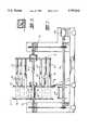
- FIG. 3is a schematic plan view of a pallet forming apparatus embodying the invention and capable of performing the method of the invention
- FIG. 4is a fragmentary elevation of part of the apparatus of FIG. 3 taken along the line 4--4 in FIG. 3;
- FIG. 5is a fragmentary elevation of a second part of the apparatus of FIG. 3 taken along the line 5--5 in FIG. 3;
- FIG. 6is a sectional end elevation taken along the line 6--6 in FIG. 5;
- FIG. 7is an end elevation of a third part of the apparatus of FIG. 3 taken along the line 7--7 in FIG. 3;
- FIG. 8is a detailed sectional elevation of the clamping strip shown in FIG. 7 taken along the line 8--8 in FIG. 7;
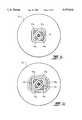
- FIGS. 9a to 9gare schematic sectional end elevations taken along the line 9--9 in FIG. 3 showing the use of the mandrels 59 to form the pallets P;
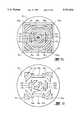
- FIG. 10is an end elevation taken along the line 10--10 in FIG. 7 showing the positioning of the mandrels 59 in the winding reel flange 52.
- the pallet Pis formed from a continuous strip of single-face corrugated board B wound in multiple layers to define a continuous supporting element P 1 defining a central square opening P 2 , which may alternatively be round, a pair of opposed generally triangular openings P 3 , P 4 , a pair of opposed truncated triangular openings P 5 , P 6 at 90° to the triangular openings P 3 , P 4 , a further pair of larger truncated triangular openings P 7 , P 8 , located at 45° to the preceding pair, a further pair of slightly larger truncated triangular openings P 9 , P 10 at 90° to the preceding pair, two further opposed pairs of larger truncated triangular openings P 11 , P 12 , P 13 , P 14 , at 45° to each of the preceding openings P 9
- the triangular and truncated triangular openings in the pallet Pare present for the purpose of generating a final pallet shape which is substantially square, and for providing cross beam members which are at a 45° angle to the principal direction of support by the lifting forks between the feet described below. These beam members provide the resistance to bending of the pallet when the pallet is lifted by forks carrying a load.
- the arrangement of openingsreduces the amount of corrugated board B used to form the pallet while ensuring that the resistance to bending of the pallet will be satisfactorily met by the beam members.
- the pallet Pis provided with three elongate generally rectangular feet F 1 , F 2 and F 3 , which comprise wound single-face corrugated board B defining an open rectangular loop of the configuration shown in FIGS. 1 and 2.
- the edges of the feet which are to contact a support surfacemay be treated to prevent damage by moisture.
- the edgesmay be dipped in water-proofing wax or may have thin particle board laminated to their lowermost faces.
- the provision of separate feet which are adhesively secured to the lower face of the palletis a preferred method of providing fork access for the pallet since the provision of slots in the pallet structure may undesirably weaken the structure.
- the apparatus embodying the inventioncomprises means 1 for supporting a roll R of single-face corrugated board B, tensioning means 2 for tensioning the corrugated board B as it is paid out from the roll R, slitting and advancing means 3 for converting the corrugated board B into a multiplicity of parallel narrow strips S, adhesive applying means 4 positioned to apply adhesive to the corrugated side of the strips S, a forming reel 5 to which the strips are secured to facilitate winding of the strips into shaped structures, reciprocating mandrel means 53, 59 for defining shaped openings in the structure as the strips S are wound on the reel 5, and severing means 7 for initially trimming the leading edge of the strips S and for severing the strips S when the winding operation is completed.
- the roll supporting means Icomprises a shaft 10 which passes through the roll R and engages at either end, supporting cradles 12, on a frame 14, so that the roll R is freely rotatably supported.
- the tensioning means 2comprises a driven roller 21 having a friction surface 22 about which the board B passes, an idler roller 24, and a support roller 26, which are rotatably mounted on the frame 14, the roller 26 being positioned to guide the board B horizontally between guide rollers 28 towards the slitting and advancing means 3.
- the rollers 21, 24 and 26are suitably rotatably mounted on the frame 14 as shown.
- the slitting and advancing means 3comprises a driven slitting roller 30 having a multiplicity of spaced radially extending parallel slitting blades 31 which, in the present embodiment, are spaced to slit the corrugated board B into six narrow strips S of equal width.
- a trimming blade 32is positioned adjacent the slitting roller 30 and operates to initially trim the board B along a line perpendicular to the line of slitting before the advancing means is operated, and for severing the strips S when the winding operation has been completed.
- the advancing meanscomprises a cross-bar 33 mounted for reciprocating movement on guide rods 34 mounted at either side of the apparatus, the cross-bar 33 supporting six pneumatic clamps 35 which operate to clamp each strip S to the cross-bar 33 which is driven along the guide rods 34 by a chain drive mechanism 35 to facilitate advancing of the strips S from their starting position to an operative position on the winding reel 5.
- the strips Sare secured to the winding reel 5, in a manner to be described further below, and the advancing means 3 is allowed to return to its rest position prior to the winding operation commencing.
- the adhesive applicator 4comprises a driven applicator roller 40 arranged over a trough 41 containing adhesive A so that the surface of the roller 40 contacts the adhesive in the trough 41.
- the strips Sare held in contact with the applicator roller 40 by a roller 43 on arms 44 pivoted to the frame 45 of the machine and the required quantity of adhesive is transferred to the corrugated side of the strips as the strips are wound onto the reel 5 in the manner to be described below.
- a hot melt adhesive applicator 46is mounted on the frame 44 over the strips S and operates to apply hot melt adhesive to the upper surface of the strips S as the winding operation nears completion so that the outermost layers of the strips S are more positively adhesively secured to prevent unwinding.
- the winding reel 5comprises parallel flanges 51, 52, between which the strips are wound as described further below.
- a central square mandrel 53passes through a central opening in the flange 52 under the control of a pneumatic cylinder 54, and includes a clamping strip 55 (FIG. 8) under which the leading edges of the strips S are clamped at the commencement of the winding operation.
- the flange 51is rotatably driven by a chain drive mechanism 56 via a drive shaft 57 driven by a motor 58, the speed of which is controlled by a central programmed controller C.
- the flange 52also carries a further series of pneumatically operated mandrels 59 3 to 59 18 (corresponding to openings P 3 to P 18 ) arranged at spaced positions from the central mandrel 53 on a supporting frame 60 so as to define the openings in the pallet described in greater detail above.
- Each mandrel 59 3 to 59 18is advanced through a shaped opening (FIG. 10) in the flange 52 into the space between the flanges 51 and 52 by corresponding pneumatic cylinders 61 3 to 61 18 under the control of the controller C which ensures that the mandrels 59 3 to 59 18 , are advanced at the appropriate time during the winding operation.
- the apparatus embodying the inventionoperates in an essentially automatic manner under the control of the central controller C and is able to form six lightweight pallets in approximately 5.5 minutes. It is envisaged that as many as 10 strips S could be cut from a wider roll R of board B thereby further increasing the output of the apparatus.
- a roll R of single-face corrugated boardis mounted on the shaft 10 which is then engaged with the cradles 12 for free rotation with respect to the frame 14.
- a length of board Bis unwound and fed around the tensioning roller 22, behind the idler roller 24 and over the support roller 26 and between guide rollers 28 until the leading end of the board B reaches the slitting roller 30.
- the slitting roller 30is rotated to feed the board through the apparatus to a position in which the leading end is adjacent the trimming blade 32 and the end is trimmed square, whereupon the strips S are advanced to a position over the cross-bar 33 and under the pneumatic clamps 35 which are operated to clamp the strips S to the cross-bar 33.
- the central mandrel 53is positioned between the flanges 51 and 52 and the advancing means is actuated to position the leading ends of the strips S adjacent the clamping strip 55 on the mandrel 53 and the ends of the strips S are clamped to the central mandrel 53 and the winding operation commences.
- the mandrels 59 3 to 59 18are withdrawn and the pallet structures P are pushed from the space between the flanges 51 and 52 by a pushing mechanism (not shown) and are carried by a roller conveyor 62 to a removal position.
- a separate winding reelsimilar to the winding reel 5, but having only a single elongate rectangular mandrel (not shown) is used to form the feet F 1 , to F 3 of the pallet described above, and the feet F 1 to F 3 are subsequently adhesively secured in the manner shown to the pallet structure P.
- the feetbe formed in some other way or from some other material, although the use of corrugated board is convenient for recycling purposes.
- the need to form feetmay be avoided by forming the pallet structure from wider strips S of corrugated board and forming lifting fork slots or grooves in one face of the pallet structure. This method of forming fork openings is not preferred since the addition of legs of the type described above provides further strength to the finished pallet structure.
Landscapes
- Engineering & Computer Science (AREA)
- Mechanical Engineering (AREA)
- Making Paper Articles (AREA)
Abstract
Description
Claims (7)
Priority Applications (1)
| Application Number | Priority Date | Filing Date | Title |
|---|---|---|---|
| US08/485,683US5797832A (en) | 1991-02-22 | 1995-06-07 | Apparatus and method for forming lightweight pallets |
Applications Claiming Priority (5)
| Application Number | Priority Date | Filing Date | Title |
|---|---|---|---|
| AUPK4761 | 1991-02-22 | ||
| AUPK476191 | 1991-02-22 | ||
| US83851892A | 1992-02-19 | 1992-02-19 | |
| US07/969,041US5448956A (en) | 1991-02-22 | 1992-10-30 | One-way lightweight pallet |
| US08/485,683US5797832A (en) | 1991-02-22 | 1995-06-07 | Apparatus and method for forming lightweight pallets |
Related Parent Applications (1)
| Application Number | Title | Priority Date | Filing Date |
|---|---|---|---|
| US07/969,041Continuation-In-PartUS5448956A (en) | 1991-02-22 | 1992-10-30 | One-way lightweight pallet |
Publications (1)
| Publication Number | Publication Date |
|---|---|
| US5797832Atrue US5797832A (en) | 1998-08-25 |
Family
ID=27157597
Family Applications (1)
| Application Number | Title | Priority Date | Filing Date |
|---|---|---|---|
| US08/485,683Expired - Fee RelatedUS5797832A (en) | 1991-02-22 | 1995-06-07 | Apparatus and method for forming lightweight pallets |
Country Status (1)
| Country | Link |
|---|---|
| US (1) | US5797832A (en) |
Cited By (17)
| Publication number | Priority date | Publication date | Assignee | Title |
|---|---|---|---|---|
| US6354229B1 (en)* | 1999-12-06 | 2002-03-12 | Bruce T. Heidtke | Shipping platform |
| US6612247B1 (en)* | 2002-09-11 | 2003-09-02 | St. Marys Box Co. Inc. | Corrugated shipping pallet |
| WO2004024576A1 (en)* | 2002-09-11 | 2004-03-25 | St Marys Box Co. Inc. | Corregated shipping pallet and support member |
| US20070006450A1 (en)* | 2003-12-16 | 2007-01-11 | Jaen Jose B | Pallet assembling machine |
| US20080060747A1 (en)* | 2005-05-12 | 2008-03-13 | Dyne Technology Co., Ltd. | Paper tube and method of making the same |
| US20080216654A1 (en)* | 1996-04-26 | 2008-09-11 | Donaldson Company, Inc. | Fluted filter media |
| US20090223421A1 (en)* | 2008-03-05 | 2009-09-10 | James A. Donovan | Shipping pallet |
| US20100107933A1 (en)* | 2006-07-13 | 2010-05-06 | David Michael Love | Shipping pallet apparatus and method |
| RU2420440C1 (en)* | 2007-06-07 | 2011-06-10 | Сейнт-Мэриз Бокс Ко. Инк. | Device to roll paper for producing articles |
| US20110168766A1 (en)* | 2009-12-03 | 2011-07-14 | Erdie Jason S | Triangular shipping container with polygonal inner support |
| WO2012021209A1 (en)* | 2010-08-13 | 2012-02-16 | Erdie Jason S | Elongate structures and devices and methods for manufacturing same |
| CN104023885A (en)* | 2012-01-09 | 2014-09-03 | 伊斯卡有限公司 | Cutting insert with hole orientation marking and method for marking hole orientation marking |
| US9174768B2 (en) | 2012-08-16 | 2015-11-03 | Intraloque Licensing Group, Inc | Apparatus for fabrication of a structural member and related fabrication methods |
| US20160263817A1 (en)* | 2013-10-22 | 2016-09-15 | Peugeot Citroen Automobiles Sa | Method for stiffening a curved sheet-metal panel by means of a cardboard panel |
| US20160304240A1 (en)* | 2012-06-27 | 2016-10-20 | Design Pallets, Inc. | Corrugated pallet constructed of folded, interlocked blanks and method |
| US9580205B1 (en)* | 2012-06-27 | 2017-02-28 | Lifdek Corporation | Corrugated pallet shipping method |
| US10858237B2 (en) | 2018-03-12 | 2020-12-08 | Atlanta Attachment Company | System and method for forming a foundation truss |
Citations (22)
| Publication number | Priority date | Publication date | Assignee | Title |
|---|---|---|---|---|
| US484041A (en)* | 1892-10-11 | Box-machine | ||
| US1747367A (en)* | 1928-12-29 | 1930-02-18 | Cartoning Machinery Corp | Circular feeding and folding mechanism |
| US2016052A (en)* | 1933-01-23 | 1935-10-01 | Roeder Fritz | Combined paper punching and folding machine |
| US2197782A (en)* | 1937-09-25 | 1940-04-23 | Dixie Vortex Co | Container making machine |
| US2691500A (en)* | 1952-02-07 | 1954-10-12 | Int Paper Co | Pallet |
| US2732063A (en)* | 1956-01-24 | Wrapper | ||
| US2856826A (en)* | 1957-04-19 | 1958-10-21 | Martinson Machine Company | Machine and method for forming disposable paper pallets |
| US2970797A (en)* | 1959-03-02 | 1961-02-07 | Theodore J Desbois | Pallet |
| US3196759A (en)* | 1963-11-08 | 1965-07-27 | Palmer | Method of folding plastic containers |
| US3199670A (en)* | 1962-04-30 | 1965-08-10 | Monsanto Co | Container |
| US3240611A (en)* | 1962-08-29 | 1966-03-15 | Beverly E Williams | Process for making plastic-coated containers and process of packaging, utilizing said containers |
| US3732790A (en)* | 1969-12-25 | 1973-05-15 | Nisso Kk | Corrugated container and method and apparatus for manufacturing the same |
| US3919925A (en)* | 1973-04-10 | 1975-11-18 | Akio Hayama | Process and equipment for continuous manufacture of corrugated cardboard box |
| US4398904A (en)* | 1979-07-02 | 1983-08-16 | Inlands Aktiebolag | Machine for producing bodies of conical receptacles |
| US4441948A (en)* | 1981-10-28 | 1984-04-10 | Macmillan Bloedel Limited | Method and apparatus for constructing multiple layer corrugated board containers |
| US4551124A (en)* | 1983-02-03 | 1985-11-05 | Don Mowry Flexo Parts, Inc. | Corrugated box machine glue apparatus |
| US4792325A (en)* | 1986-09-29 | 1988-12-20 | Schmidtke Joachim G | Method and apparatus for manufacturing cardboard pallets |
| US5184558A (en)* | 1991-11-27 | 1993-02-09 | Gaylord Container Corporation | Pallet and method and apparatus for making same |
| US5336042A (en)* | 1992-03-05 | 1994-08-09 | Kinetic Robotics Inc. | Palletizer with cap forming |
| US5372570A (en)* | 1991-06-26 | 1994-12-13 | Fabmation, Inc. | Method and apparatus for folding of sheet material |
| US5448956A (en)* | 1991-02-22 | 1995-09-12 | Visy Board Properties Pty. Ltd. | One-way lightweight pallet |
| US5569148A (en)* | 1992-11-23 | 1996-10-29 | Bay Corrugated Container, Inc. | Method and apparatus for manufacturing pallet spacers |
- 1995
- 1995-06-07USUS08/485,683patent/US5797832A/ennot_activeExpired - Fee Related
Patent Citations (22)
| Publication number | Priority date | Publication date | Assignee | Title |
|---|---|---|---|---|
| US2732063A (en)* | 1956-01-24 | Wrapper | ||
| US484041A (en)* | 1892-10-11 | Box-machine | ||
| US1747367A (en)* | 1928-12-29 | 1930-02-18 | Cartoning Machinery Corp | Circular feeding and folding mechanism |
| US2016052A (en)* | 1933-01-23 | 1935-10-01 | Roeder Fritz | Combined paper punching and folding machine |
| US2197782A (en)* | 1937-09-25 | 1940-04-23 | Dixie Vortex Co | Container making machine |
| US2691500A (en)* | 1952-02-07 | 1954-10-12 | Int Paper Co | Pallet |
| US2856826A (en)* | 1957-04-19 | 1958-10-21 | Martinson Machine Company | Machine and method for forming disposable paper pallets |
| US2970797A (en)* | 1959-03-02 | 1961-02-07 | Theodore J Desbois | Pallet |
| US3199670A (en)* | 1962-04-30 | 1965-08-10 | Monsanto Co | Container |
| US3240611A (en)* | 1962-08-29 | 1966-03-15 | Beverly E Williams | Process for making plastic-coated containers and process of packaging, utilizing said containers |
| US3196759A (en)* | 1963-11-08 | 1965-07-27 | Palmer | Method of folding plastic containers |
| US3732790A (en)* | 1969-12-25 | 1973-05-15 | Nisso Kk | Corrugated container and method and apparatus for manufacturing the same |
| US3919925A (en)* | 1973-04-10 | 1975-11-18 | Akio Hayama | Process and equipment for continuous manufacture of corrugated cardboard box |
| US4398904A (en)* | 1979-07-02 | 1983-08-16 | Inlands Aktiebolag | Machine for producing bodies of conical receptacles |
| US4441948A (en)* | 1981-10-28 | 1984-04-10 | Macmillan Bloedel Limited | Method and apparatus for constructing multiple layer corrugated board containers |
| US4551124A (en)* | 1983-02-03 | 1985-11-05 | Don Mowry Flexo Parts, Inc. | Corrugated box machine glue apparatus |
| US4792325A (en)* | 1986-09-29 | 1988-12-20 | Schmidtke Joachim G | Method and apparatus for manufacturing cardboard pallets |
| US5448956A (en)* | 1991-02-22 | 1995-09-12 | Visy Board Properties Pty. Ltd. | One-way lightweight pallet |
| US5372570A (en)* | 1991-06-26 | 1994-12-13 | Fabmation, Inc. | Method and apparatus for folding of sheet material |
| US5184558A (en)* | 1991-11-27 | 1993-02-09 | Gaylord Container Corporation | Pallet and method and apparatus for making same |
| US5336042A (en)* | 1992-03-05 | 1994-08-09 | Kinetic Robotics Inc. | Palletizer with cap forming |
| US5569148A (en)* | 1992-11-23 | 1996-10-29 | Bay Corrugated Container, Inc. | Method and apparatus for manufacturing pallet spacers |
Cited By (28)
| Publication number | Priority date | Publication date | Assignee | Title |
|---|---|---|---|---|
| US8268053B2 (en) | 1996-04-26 | 2012-09-18 | Donaldson Company, Inc. | Fluted filter media |
| US8460442B2 (en) | 1996-04-26 | 2013-06-11 | Donaldson Company, Inc. | Fluted filter media |
| US20080216654A1 (en)* | 1996-04-26 | 2008-09-11 | Donaldson Company, Inc. | Fluted filter media |
| US6354229B1 (en)* | 1999-12-06 | 2002-03-12 | Bruce T. Heidtke | Shipping platform |
| US6612247B1 (en)* | 2002-09-11 | 2003-09-02 | St. Marys Box Co. Inc. | Corrugated shipping pallet |
| WO2004024576A1 (en)* | 2002-09-11 | 2004-03-25 | St Marys Box Co. Inc. | Corregated shipping pallet and support member |
| US6736074B2 (en) | 2002-09-11 | 2004-05-18 | St. Marys Box Co. Inc. | Lightweight wood substitute support member |
| US20070006450A1 (en)* | 2003-12-16 | 2007-01-11 | Jaen Jose B | Pallet assembling machine |
| US7472474B2 (en)* | 2003-12-16 | 2009-01-06 | Jose Boix Jaen | Pallet assembling machine |
| US8337375B2 (en) | 2005-05-12 | 2012-12-25 | Dyne Technology Co., Ltd. | Apparatus and method for making tube with polygonal cross-section |
| US20080060747A1 (en)* | 2005-05-12 | 2008-03-13 | Dyne Technology Co., Ltd. | Paper tube and method of making the same |
| US9663267B2 (en) | 2006-07-13 | 2017-05-30 | Intraloque Licensing Group, Inc. | Shipping pallet apparatus and method |
| US20100107933A1 (en)* | 2006-07-13 | 2010-05-06 | David Michael Love | Shipping pallet apparatus and method |
| RU2420440C1 (en)* | 2007-06-07 | 2011-06-10 | Сейнт-Мэриз Бокс Ко. Инк. | Device to roll paper for producing articles |
| US20090223421A1 (en)* | 2008-03-05 | 2009-09-10 | James A. Donovan | Shipping pallet |
| US20110168766A1 (en)* | 2009-12-03 | 2011-07-14 | Erdie Jason S | Triangular shipping container with polygonal inner support |
| US8459190B2 (en) | 2009-12-03 | 2013-06-11 | Jason S. Erdie | Triangular shipping container with polygonal inner support |
| WO2012021209A1 (en)* | 2010-08-13 | 2012-02-16 | Erdie Jason S | Elongate structures and devices and methods for manufacturing same |
| CN104023885A (en)* | 2012-01-09 | 2014-09-03 | 伊斯卡有限公司 | Cutting insert with hole orientation marking and method for marking hole orientation marking |
| CN104023885B (en)* | 2012-01-09 | 2017-06-20 | 伊斯卡有限公司 | Cutting insert with hole orientation marking and method for marking hole orientation marking |
| US20160304240A1 (en)* | 2012-06-27 | 2016-10-20 | Design Pallets, Inc. | Corrugated pallet constructed of folded, interlocked blanks and method |
| US9580205B1 (en)* | 2012-06-27 | 2017-02-28 | Lifdek Corporation | Corrugated pallet shipping method |
| US9174768B2 (en) | 2012-08-16 | 2015-11-03 | Intraloque Licensing Group, Inc | Apparatus for fabrication of a structural member and related fabrication methods |
| US20160263817A1 (en)* | 2013-10-22 | 2016-09-15 | Peugeot Citroen Automobiles Sa | Method for stiffening a curved sheet-metal panel by means of a cardboard panel |
| US10201937B2 (en)* | 2013-10-22 | 2019-02-12 | Adhex Technologies | Method for stiffening a curved sheet-metal panel by means of a cardboard panel |
| US10858237B2 (en) | 2018-03-12 | 2020-12-08 | Atlanta Attachment Company | System and method for forming a foundation truss |
| US11407633B2 (en) | 2018-03-12 | 2022-08-09 | Atlanta Attachment Company | System and method for forming a foundation truss |
| US11845649B2 (en) | 2018-03-12 | 2023-12-19 | Atlanta Attachment Company | System and method for forming a foundation truss |
Similar Documents
| Publication | Publication Date | Title |
|---|---|---|
| US5797832A (en) | Apparatus and method for forming lightweight pallets | |
| US4732630A (en) | Method for producing expandable honeycomb material | |
| US3599888A (en) | Method of and means for severing web strip material upon completion of winding a roll and initiating winding of a new roll | |
| CA2075142C (en) | Process for the production of a honeycomb core from foil strip, equipment for carrying out the process, and use of the honeycomb core for the continuous production of a composite plate | |
| US4878986A (en) | Web butt splicing device | |
| US3307326A (en) | Corrugated board bundler | |
| US4964585A (en) | Slitting and rewiding machine | |
| US4692196A (en) | Apparatus and method for wrapping an external tape support about a filter element assembly | |
| US5031498A (en) | Apparatus for stacking and cutting rolls of paper | |
| US3977627A (en) | Winding and slitting apparatus | |
| US4178739A (en) | Construction for applying tape | |
| ITRM950049A1 (en) | METHOD AND APPARATUS FOR THE PRODUCTION OF SUPPORTS FOR PALETS AND PALETTE INCLUDING SAID SUPPORTS | |
| WO1996038291A1 (en) | Apparatus and method for forming lightweight pallets | |
| AU701393B2 (en) | Apparatus and method for forming lightweight pallets | |
| US3135644A (en) | Continuous veneer core, and method and apparatus for making the same | |
| US3741840A (en) | Method for producing continuous compressed honeycomb | |
| EP1462366B1 (en) | Method and device for applying a wrapping plastic film around a product to be packaged | |
| CN114451614A (en) | False eyelashes processing device | |
| EP1925554A1 (en) | Banding machine and method for banding pallets | |
| US3235430A (en) | Method and apparatus for forming cut preforms from wound laminate material | |
| US3695966A (en) | Method of manufacturing furniture fabrication cores | |
| CN222408664U (en) | A film-drawing and cutting device for electronic cigarette outer packaging film coating | |
| FI87548B (en) | ANORDNING FOER BEHANDLING AV ETT CELLSTRUKTURMATERIAL | |
| CN207771888U (en) | an automatic cutting machine | |
| JPS641204Y2 (en) |
Legal Events
| Date | Code | Title | Description |
|---|---|---|---|
| AS | Assignment | Owner name:VISY PAPER PTY LTD, AUSTRALIA Free format text:ASSIGNMENT OF ASSIGNORS INTEREST;ASSIGNORS:ONG, ALEX;CHIODO, ROSS;MAMMOLITI, JOHN;REEL/FRAME:007565/0609 Effective date:19950530 | |
| AS | Assignment | Owner name:VISY BOARD PROPERTIES PTY LTD, AUSTRALIA Free format text:ASSIGNMENT OF ASSIGNORS INTEREST;ASSIGNOR:VISY PAPER PTY LTD;REEL/FRAME:008021/0130 Effective date:19960522 | |
| FEPP | Fee payment procedure | Free format text:PAYOR NUMBER ASSIGNED (ORIGINAL EVENT CODE: ASPN); ENTITY STATUS OF PATENT OWNER: LARGE ENTITY | |
| FPAY | Fee payment | Year of fee payment:4 | |
| AS | Assignment | Owner name:VISY R & D PTY LTD, AUSTRALIA Free format text:ASSIGNMENT OF ASSIGNORS INTEREST;ASSIGNOR:VISY BOARD PROPERTIES PTY LTD;REEL/FRAME:015478/0870 Effective date:20040625 | |
| FPAY | Fee payment | Year of fee payment:8 | |
| REMI | Maintenance fee reminder mailed | ||
| LAPS | Lapse for failure to pay maintenance fees | ||
| STCH | Information on status: patent discontinuation | Free format text:PATENT EXPIRED DUE TO NONPAYMENT OF MAINTENANCE FEES UNDER 37 CFR 1.362 | |
| FP | Lapsed due to failure to pay maintenance fee | Effective date:20100825 |