US5797770A - Shielded electrical connector - Google Patents
Shielded electrical connectorDownload PDFInfo
- Publication number
- US5797770A US5797770AUS08/701,227US70122796AUS5797770AUS 5797770 AUS5797770 AUS 5797770AUS 70122796 AUS70122796 AUS 70122796AUS 5797770 AUS5797770 AUS 5797770A
- Authority
- US
- United States
- Prior art keywords
- shell
- housing
- receiving cavities
- outer shell
- plug receiving
- Prior art date
- Legal status (The legal status is an assumption and is not a legal conclusion. Google has not performed a legal analysis and makes no representation as to the accuracy of the status listed.)
- Expired - Lifetime
Links
Images


Classifications
- H—ELECTRICITY
- H01—ELECTRIC ELEMENTS
- H01R—ELECTRICALLY-CONDUCTIVE CONNECTIONS; STRUCTURAL ASSOCIATIONS OF A PLURALITY OF MUTUALLY-INSULATED ELECTRICAL CONNECTING ELEMENTS; COUPLING DEVICES; CURRENT COLLECTORS
- H01R13/00—Details of coupling devices of the kinds covered by groups H01R12/70 or H01R24/00 - H01R33/00
- H01R13/648—Protective earth or shield arrangements on coupling devices, e.g. anti-static shielding
- H01R13/658—High frequency shielding arrangements, e.g. against EMI [Electro-Magnetic Interference] or EMP [Electro-Magnetic Pulse]
- H—ELECTRICITY
- H01—ELECTRIC ELEMENTS
- H01R—ELECTRICALLY-CONDUCTIVE CONNECTIONS; STRUCTURAL ASSOCIATIONS OF A PLURALITY OF MUTUALLY-INSULATED ELECTRICAL CONNECTING ELEMENTS; COUPLING DEVICES; CURRENT COLLECTORS
- H01R12/00—Structural associations of a plurality of mutually-insulated electrical connecting elements, specially adapted for printed circuits, e.g. printed circuit boards [PCB], flat or ribbon cables, or like generally planar structures, e.g. terminal strips, terminal blocks; Coupling devices specially adapted for printed circuits, flat or ribbon cables, or like generally planar structures; Terminals specially adapted for contact with, or insertion into, printed circuits, flat or ribbon cables, or like generally planar structures
- H01R12/70—Coupling devices
- H01R12/7005—Guiding, mounting, polarizing or locking means; Extractors
- H01R12/7011—Locking or fixing a connector to a PCB
- H01R12/7017—Snap means
- H01R12/7023—Snap means integral with the coupling device
- H—ELECTRICITY
- H01—ELECTRIC ELEMENTS
- H01R—ELECTRICALLY-CONDUCTIVE CONNECTIONS; STRUCTURAL ASSOCIATIONS OF A PLURALITY OF MUTUALLY-INSULATED ELECTRICAL CONNECTING ELEMENTS; COUPLING DEVICES; CURRENT COLLECTORS
- H01R12/00—Structural associations of a plurality of mutually-insulated electrical connecting elements, specially adapted for printed circuits, e.g. printed circuit boards [PCB], flat or ribbon cables, or like generally planar structures, e.g. terminal strips, terminal blocks; Coupling devices specially adapted for printed circuits, flat or ribbon cables, or like generally planar structures; Terminals specially adapted for contact with, or insertion into, printed circuits, flat or ribbon cables, or like generally planar structures
- H01R12/70—Coupling devices
- H01R12/71—Coupling devices for rigid printing circuits or like structures
- H01R12/712—Coupling devices for rigid printing circuits or like structures co-operating with the surface of the printed circuit or with a coupling device exclusively provided on the surface of the printed circuit
- H01R12/716—Coupling device provided on the PCB
Definitions
- the inventionrelates to a shielded electrical connector, and more particularly, to a shielded electrical connector with a shielding shell that encircles an insulating housing.
- U.S. Pat. No. 5,161,999, and U.S. Pat. No. 5,167,531discloses a shielded connector assembly constructed with two electrical headers for connection to plug type electrical connectors. Two shells encircle respective headers to provide shielding. The headers and the two shells are mounted to a conducting bracket. A third shell mounts on the bracket and covers a rear of each of the headers.
- This connector assemblyis bulky, because of a relatively large number of separate parts, comprising a mounting bracket, two headers, two shells encircling respective headers, and a third shell. It would be desirable to provide an electrical connector comprising multiple plug receiving cavities, wherein each of the plug receiving cavities is encircled by shielding, and wherein the connector is comprised of a reduced number of separate parts to achieve a compact size.
- U.S. Pat. No. 5,387,114discloses a shielded electrical connector comprising a conducting outer shell encircling an insulating housing, and a conducting second shell engaging the outer shell. Electrical contacts are received inside respective cavities in the housing.
- the second shellextends along slots in the housing; the slots are beside the cavities without being inside the cavities, with portions of the housing separating the slots from the cavities. These housing portions prevent the second shell from engaging portions of a mating plug type connector that are to be inserted inside the cavities for mating with the contacts therewithin.
- the inventionpertains to a shielded electrical connector, a compact size of which is achieved by extending a conducting shell inside multiple plug receiving cavities to engage respective plugs that are to mate with electrical contacts inside the cavities.
- the inventionis constructed with a reduced number of parts, as compared with prior electrical connectors, thereby simplifying assembly and reducing fabrication costs.
- An advantage of the inventionresides in shielding that completely encircles multiple plug receiving cavities, the shielding comprising a second shell engaging an outer shell, the second shell extending inside the multiple plug receiving cavities to achieve a compact construction.
- a shielded electrical connectorcomprises an insulating housing, a conducting outer shell encircling the housing, and a conducting second shell engaging the outer shell to provide electrical shielding, electrical contacts extending inside multiple plug receiving cavities in the housing, the second shell extending inside each of the plug receiving cavities to engage electrical plug type connectors to be received in the plug receiving cavities.
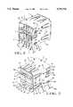
- FIG. 1is an isometric view of an electrical connector with parts being separated from one another;
- FIGS. 2 and 3are isometric rear and front views of the connector shown in FIG. 1;
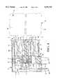
- FIG. 4is a side view in section of the connector shown in FIG. 1, together with two mating plug type electrical connectors shown in dotted outlines;
- FIG. 5is an isometric view of an insulating housing that is a part of the connector shown in FIG. 1;
- FIG. 6is an isometric view of a second shell that is a part of the connector shown in FIG. 1;
- FIG. 7is an isometric view of a rear of the housing that is shown in FIG. 5;
- FIGS. 8 and 9are isometric views of conductive electrical contacts that are part of the connector shown in FIG. 1;
- FIG. 10is an isometric view of a rear of the housing shown in FIG. 5, together with the contacts shown in FIGS. 8 and 9;
- FIG. 11is an isometric view of a front of a conductive outer shell that is a part of the connector shown in FIG. 1;
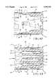
- FIG. 12is a top view in section of the connector shown in FIG. 1 illustrating the second shell in a plug receiving cavity of the housing;
- FIG. 13is a top view in section of the connector shown in FIG. 1 illustrating a row of contacts in a plug receiving cavity of the housing.
- an electrical connector 1comprises two rows of electrical contacts 2 inside respective plug receiving cavities 3 in an insulating housing 4, and shielding 5 comprising a conducting outer shell 6 encircling the housing 4 and a conducting second shell 7 inside the outer shell 6 and inside the plug receiving cavities 3.
- the connector 1is shown as having two plug receiving cavities 3.
- respective electrical plug connectors 8are to be inserted into respective plug receiving cavities 3 to mate with the connector 1.
- Each of the plug connectors 8comprises, a conductive shell 9 projecting from an insulating overmold 10.
- each of the plug connectors 8further comprises, an insulating housing surrounded by the shell 9, and electrical mating contacts in the housing to be inserted into respective plug receiving cavities 3 of the connector 1 to engage and electrically connect with the contacts 2 in the connector 1.
- General construction of a mating electrical plug connector 8is described in U.S. Pat. No. 5,017,156 and in U.S. Pat. No. 5,267,882.
- the housing 4is of unitary, molded plastic construction.
- a partition 11 on the housingprojects forwardly between the two plug receiving cavities 3 with opposite sides or surfaces thereof facing respective plug receiving cavities 3.
- the cavities 3have similar constructions, with the construction of one of the cavities 3 being inverted with respect to the construction of the other of the cavities 3.
- Second partitions 12 parallel to the partition 11divide respective plug receiving cavities 3 into two parts, each of the cavities being divided into a shell receiving cavity section 13 and a contact receiving cavity section 14.
- Each of the contacts 2is of unitary construction, stamped and formed from metal.
- the terminal 17 on the contact 2 shown in FIG. 8is relatively longer than a relatively shorter terminal 17 on the contact 2 shown in FIG. 9.
- a widened mounting section 18 rearward of the spring 15has barbed edges
- a widened mounting section 19 on the terminal 17has barbed edges.
- multiple contact receiving passages 20project forwardly from a rear of the housing and are arranged in an upper row and a lower row.
- a widened slot 21extends across a top of each of the passages 20.
- the longer contacts 2project through respective passages 20 in the upper row while the shorter contacts 2 project through respective passages 20 in the lower row.
- the widened sections 18 on the contacts 2are wedged in respective slots 21 to restrain the contacts 2 from movement.
- each row of passages 20projects rearwardly from a remainder of the housing 4.
- Elongated terminal receiving slots 23communicate with a rear of each of the contact spacer plates 22.
- the slots 23 in an upper one of the plates 22are aligned with respective slots 23 in a lower one of the plates 22.
- the terminals 17 of the contacts 2project rearwardly from respective passages 20 and project downwardly and through corresponding slots 23.
- the shorter terminals 17 of the contacts 2project through corresponding slots 23 in the lower plate 22 while the longer terminals 17 project through slots 23 in both plates 22.
- each slot 23 in the lower plate 22receives two terminals 17.
- the terminals 17are aligned by the plates 22 for mounting in apertures through a circuit board, not shown.
- the widened section 19 on each terminal 17is wedged in a corresponding slot 23 in the lower plate 22 to restrain the terminal 17 from movement.
- the curved contact portions 15 on respective electrical contacts 2extend along the passages 20.
- the passages 20open into respective plug receiving cavities 3, forming grooves along respective partitions 12.
- the contact portions 15extend along the grooves, facing into and exposed within the contact receiving cavities 14.
- the conducting second shell 7is of unitary construction, stamped and formed from a sheet of metal that has a thickness plane, forming the thickness plane of the second shell 7.
- the second shell 7comprises spaced apart plates 24 that connect at bent corners 25 with respective webs 26 that extend transversely of the plates 24 An open seam 27 separates one of the webs 26 from a corresponding plate 24.
- the plates 24fit slidably along spaced apart slots 28, FIGS. 4 and 7, in the housing 4.
- the slots 28extend in the housing 4 from rear to front.
- the second shell 7is forward of the upper row of terminals 17 on the contacts 2.
- the second shell 7is assembled to and affixed within the housing 4 before such contacts 2 are assembled to the housing 4.
- Cantilever latch fingers 29project rearwardly on each plate 24, being struck out of the thickness plane of the plates 24.
- the latch fingers 29are deflected resiliently when the plates 24 are inserted along the spaced apart slots 28, and spring outwardly when they have entered respective slots 28.
- the latch fingers 29face toward a rear wall 30, FIGS. 4 and 12, in each of the slots 28 to restrain rearward movement of the second shell 7 relative to the housing 4.
- the plates 24 on the second shell 7fit slidably over, and register along, the partition 11 on the housing 4. Further, the plates 24 on the second shell 7 extend on the opposite sides of the partition 11.
- Cantilever spring fingers 31project forwardly from each plate 24.
- the spring fingers 31 on the second shell 7project forwardly of the plates 24, and extend in respective plug receiving cavities 3 to engage respective plug type electrical connectors 8 to be received in the plug receiving cavities 3.
- Each of the spring fingers 31has a curved tip 32 that projects into a corresponding trough 33 recessed in the partition 11.
- the tips 32extend along a corresponding plug receiving cavity 3 to engage respective plug type electrical connectors 8 to be received in the plug receiving cavities 3.
- the spring fingers 31 on the second shell 7extend in respective plug receiving cavities 3 together with the electrical contacts 2 in each of the plug receiving cavities 3, whereby plug type electrical connectors 8 to be received in the plug receiving cavities 3 will be engaged by the spring fingers 31 on the second shell 7, and by the electrical contacts 2.
- each plug 8will enter a corresponding contact section 14 to engage the contacts 15 in a corresponding row of the contacts 15.
- the conducting shell 9 on the plug connector 8will enter both the contact section 14 and a corresponding shell receiving section 13 of the same plug receiving cavity 13.
- the conducting outer shell 6is of unitary construction, stamped and formed from a sheet of metal that has a thickness plane, forming the thickness plane of the outer shell 6.
- the outer shell 6comprises four walls 34 that are joined together at bent corners 35 with one of the walls 34 bifurcated by an open seam 36.
- the four walls 34encircle an open front end on the outer shell, and outwardly turned lips 37 on respective walls 34 are adjacent the open front end, and conductive outer shell 6 encircles front portions of the housing.
- the housing 4 and the outer shell 6are latched together by a latch 38, FIGS. 2 and 3, that comprises openings 39 in corresponding walls 34 on the outer shell 6 receiving projecting wedge shaped projections 40 on the housing 4.
- the projections 40are inclined in a direction from front to rear, such that the projections 40 can be urged into the open rear end of the outer shell 6, and latch in the openings 39 in corresponding walls 34.
- Slotted openings 41FIGS. 2 and 3, extending from rear to front in corresponding opposite walls 34 communicate with the open rear end on the outer shell 6.
- Elongated ribs 42 projecting from the housing 4 on opposite wallsextend along the slotted openings 41 to prevent pivoting of the outer shell 6 relative to the housing 4.
- the ribs 42enter the slotted openings 41 from the rear when the housing 4 is inserted into the open rear end.
- the four walls 34 on the outer shell 6encircle an open rear end on the outer shell 6.
- the wall 34 that is bifurcated by the seam 36has a rear opening 43, FIG. 11.
- the metal that would have been removed to form the opening 43becomes elongated electrical terminals 44 that are in alignment with the opening 43.
- the terminals 44are connected to, and project from, corresponding opposite walls 34.
- the terminals 44are for connection in openings through a circuit board, not shown, on which the connector 1 is to be mounted.
- a shoulder 45, FIGS. 4 and 5, on the housing 4faces forwardly and is received in the opening 43 to resist forward movement of the housing 4 relative to the outer shell 6.
- the housing 4is inserted into the open rear end of the outer shell 6 until the shoulder 45 faces an edge on the opening 43.
- Spring fingers 46 on each of the four walls 34 on the outer shell 6are adjacent the open front end of the outer shell 6.
- Each of the spring fingers 46is a cantilever beam with a curved tip 47 that projects inside the outer shell 6.
- the spring fingers 46 on corresponding opposite walls 34extend from front to rear.
- the spring fingers 46 on a remainder of the corresponding opposite walls 34extend from rear to front.
- Each of the spring fingers 46is bent out of the thickness plane of the outer shell 6 to project inwardly of the walls 34.
- the spring fingers 46 on the bifurcated wall 34face toward and extend along a corresponding plug receiving cavity 3, along the contact receiving section 14.
- the spring fingers 46 on an opposite wall 34is received in a shell receiving section 13 of the other plug receiving cavity 3, which shell receiving section 13 is between the outer shell 6 and a corresponding outer wall on the housing 4.
- the shell receiving recess 13extends over lateral sides on each of the partitions 12.
- the spring fingers 46 on each of the two walls 34 that join the bifurcated wall 34extend along the shell receiving recess 13, in turn, that extends over lateral sides on each of the partitions 12.
- the spring fingers 46engage the shells 9 on respective plug connectors 8, when the plug connectors 8 are received in the plug receiving cavities 3 to mate with the connector 1.
- electrical connectionis advantageously established by engagement of the outer shell 6 and the second shell 7 with each other, as well as to each shell 9 on a plug connector 8.
- the second shell 7bridges across recesses 48 in the housing.
- the outer shell 6projects into the recesses 48 and engages the second shell 7.
- additional spring fingers 49 on respective walls 34 on the outer shell 6are adjacent the rear end of the outer shell 6 and are similar in construction as compared with the spring fingers 46.
- the additional spring fingers 49 on the outer shell 6project into the recesses 48 in the housing 4 to engage respective webs 26 on the second shell 7 whereby the second shell 7 engages the outer shell 6 and establishes an electrical connection therebetween.
- An advantage of the inventionresides in shielding that completely encircles multiple plug receiving cavities, the shielding comprising a second shell engaging an outer shell, the second shell extending inside the multiple plug receiving cavities to achieve a compact construction.
- shieldingcomprising: a second shell engaging outer shell, wherein both the outer shell and the second shell extend in respective multiple plug receiving cavities of a connector, enabling both the outer shell and the second shell to engage respective electrical plug connectors to be received in the plug receiving cavities.
Landscapes
- Details Of Connecting Devices For Male And Female Coupling (AREA)
Abstract
Description
The invention relates to a shielded electrical connector, and more particularly, to a shielded electrical connector with a shielding shell that encircles an insulating housing.
Each of U.S. Pat. No. 5,161,999, and U.S. Pat. No. 5,167,531 discloses a shielded connector assembly constructed with two electrical headers for connection to plug type electrical connectors. Two shells encircle respective headers to provide shielding. The headers and the two shells are mounted to a conducting bracket. A third shell mounts on the bracket and covers a rear of each of the headers. This connector assembly is bulky, because of a relatively large number of separate parts, comprising a mounting bracket, two headers, two shells encircling respective headers, and a third shell. It would be desirable to provide an electrical connector comprising multiple plug receiving cavities, wherein each of the plug receiving cavities is encircled by shielding, and wherein the connector is comprised of a reduced number of separate parts to achieve a compact size.
U.S. Pat. No. 5,387,114 discloses a shielded electrical connector comprising a conducting outer shell encircling an insulating housing, and a conducting second shell engaging the outer shell. Electrical contacts are received inside respective cavities in the housing. The second shell extends along slots in the housing; the slots are beside the cavities without being inside the cavities, with portions of the housing separating the slots from the cavities. These housing portions prevent the second shell from engaging portions of a mating plug type connector that are to be inserted inside the cavities for mating with the contacts therewithin.
It would be desirable to provide an electrical connector with an improved compact size that is achieved by a shield extending inside multiple plug receiving cavities to engage respective plugs that are to mate with electrical contacts inside the cavities.
The invention pertains to a shielded electrical connector, a compact size of which is achieved by extending a conducting shell inside multiple plug receiving cavities to engage respective plugs that are to mate with electrical contacts inside the cavities. The invention is constructed with a reduced number of parts, as compared with prior electrical connectors, thereby simplifying assembly and reducing fabrication costs.
An advantage of the invention resides in shielding that completely encircles multiple plug receiving cavities, the shielding comprising a second shell engaging an outer shell, the second shell extending inside the multiple plug receiving cavities to achieve a compact construction.
According to an embodiment of the invention, a shielded electrical connector comprises an insulating housing, a conducting outer shell encircling the housing, and a conducting second shell engaging the outer shell to provide electrical shielding, electrical contacts extending inside multiple plug receiving cavities in the housing, the second shell extending inside each of the plug receiving cavities to engage electrical plug type connectors to be received in the plug receiving cavities.
A preferred embodiment will now be described with reference to the accompanying drawings, according to which:
FIG. 1 is an isometric view of an electrical connector with parts being separated from one another;
FIGS. 2 and 3 are isometric rear and front views of the connector shown in FIG. 1;
FIG. 4 is a side view in section of the connector shown in FIG. 1, together with two mating plug type electrical connectors shown in dotted outlines;
FIG. 5 is an isometric view of an insulating housing that is a part of the connector shown in FIG. 1;
FIG. 6 is an isometric view of a second shell that is a part of the connector shown in FIG. 1;
FIG. 7 is an isometric view of a rear of the housing that is shown in FIG. 5;
FIGS. 8 and 9 are isometric views of conductive electrical contacts that are part of the connector shown in FIG. 1;
FIG. 10 is an isometric view of a rear of the housing shown in FIG. 5, together with the contacts shown in FIGS. 8 and 9;
FIG. 11 is an isometric view of a front of a conductive outer shell that is a part of the connector shown in FIG. 1;
FIG. 12 is a top view in section of the connector shown in FIG. 1 illustrating the second shell in a plug receiving cavity of the housing; and
FIG. 13 is a top view in section of the connector shown in FIG. 1 illustrating a row of contacts in a plug receiving cavity of the housing.
With reference to FIGS. 1-4, anelectrical connector 1 comprises two rows ofelectrical contacts 2 inside respectiveplug receiving cavities 3 in aninsulating housing 4, andshielding 5 comprising a conductingouter shell 6 encircling thehousing 4 and a conductingsecond shell 7 inside theouter shell 6 and inside theplug receiving cavities 3. For example, theconnector 1 is shown as having twoplug receiving cavities 3. As shown in FIG. 4, in phantom or dotted outlines, respective electrical plug connectors 8 are to be inserted into respectiveplug receiving cavities 3 to mate with theconnector 1. Each of the plug connectors 8 comprises, a conductive shell 9 projecting from an insulating overmold 10. Although not illustrated, it should be understood that each of the plug connectors 8 further comprises, an insulating housing surrounded by the shell 9, and electrical mating contacts in the housing to be inserted into respectiveplug receiving cavities 3 of theconnector 1 to engage and electrically connect with thecontacts 2 in theconnector 1. General construction of a mating electrical plug connector 8 is described in U.S. Pat. No. 5,017,156 and in U.S. Pat. No. 5,267,882.
With reference to FIGS. 5, 7 and 10, thehousing 4 is of unitary, molded plastic construction. Apartition 11 on the housing projects forwardly between the twoplug receiving cavities 3 with opposite sides or surfaces thereof facing respectiveplug receiving cavities 3. Thecavities 3 have similar constructions, with the construction of one of thecavities 3 being inverted with respect to the construction of the other of thecavities 3.Second partitions 12 parallel to thepartition 11 divide respectiveplug receiving cavities 3 into two parts, each of the cavities being divided into a shellreceiving cavity section 13 and a contactreceiving cavity section 14.
With reference to FIGS. 8 and 9, theelectrical contacts 2 will be described. Each of thecontacts 2 is of unitary construction, stamped and formed from metal. Acantilever spring 15, formed with acurved contact portion 16, extends forwardly from anelongated terminal 17 that is bent downward. Theterminal 17 on thecontact 2 shown in FIG. 8 is relatively longer than a relativelyshorter terminal 17 on thecontact 2 shown in FIG. 9. A widenedmounting section 18 rearward of thespring 15 has barbed edges A widenedmounting section 19 on theterminal 17 has barbed edges.
With reference to FIGS. 7 and 10, multiplecontact receiving passages 20 project forwardly from a rear of the housing and are arranged in an upper row and a lower row. A widenedslot 21 extends across a top of each of thepassages 20. Thelonger contacts 2 project throughrespective passages 20 in the upper row while theshorter contacts 2 project throughrespective passages 20 in the lower row. The widenedsections 18 on thecontacts 2 are wedged inrespective slots 21 to restrain thecontacts 2 from movement.
Beneath each row ofpassages 20, a correspondingcontact spacer plate 22 projects rearwardly from a remainder of thehousing 4. Elongatedterminal receiving slots 23 communicate with a rear of each of thecontact spacer plates 22. Theslots 23 in an upper one of theplates 22 are aligned withrespective slots 23 in a lower one of theplates 22. Theterminals 17 of thecontacts 2 project rearwardly fromrespective passages 20 and project downwardly and throughcorresponding slots 23. Theshorter terminals 17 of thecontacts 2 project throughcorresponding slots 23 in thelower plate 22 while thelonger terminals 17 project throughslots 23 in bothplates 22. Thus, eachslot 23 in thelower plate 22 receives twoterminals 17. Thereby theterminals 17 are aligned by theplates 22 for mounting in apertures through a circuit board, not shown. The widenedsection 19 on each terminal 17 is wedged in acorresponding slot 23 in thelower plate 22 to restrain the terminal 17 from movement.
With reference to FIGS. 4 and 13, thecurved contact portions 15 on respectiveelectrical contacts 2 extend along thepassages 20. Thepassages 20 open into respectiveplug receiving cavities 3, forming grooves alongrespective partitions 12. Thecontact portions 15 extend along the grooves, facing into and exposed within thecontact receiving cavities 14.
With reference to FIGS. 4, 6, 10 and 12, the conductingsecond shell 7 is of unitary construction, stamped and formed from a sheet of metal that has a thickness plane, forming the thickness plane of thesecond shell 7. Thesecond shell 7 comprises spaced apartplates 24 that connect atbent corners 25 withrespective webs 26 that extend transversely of theplates 24 Anopen seam 27 separates one of thewebs 26 from acorresponding plate 24. Theplates 24 fit slidably along spaced apartslots 28, FIGS. 4 and 7, in thehousing 4. Theslots 28 extend in thehousing 4 from rear to front. As shown in FIG. 2, thesecond shell 7 is forward of the upper row ofterminals 17 on thecontacts 2. Thus, thesecond shell 7 is assembled to and affixed within thehousing 4 beforesuch contacts 2 are assembled to thehousing 4.Cantilever latch fingers 29 project rearwardly on eachplate 24, being struck out of the thickness plane of theplates 24. Thelatch fingers 29 are deflected resiliently when theplates 24 are inserted along the spaced apartslots 28, and spring outwardly when they have enteredrespective slots 28. Thelatch fingers 29 face toward arear wall 30, FIGS. 4 and 12, in each of theslots 28 to restrain rearward movement of thesecond shell 7 relative to thehousing 4.
Theplates 24 on thesecond shell 7 fit slidably over, and register along, thepartition 11 on thehousing 4. Further, theplates 24 on thesecond shell 7 extend on the opposite sides of thepartition 11.Cantilever spring fingers 31 project forwardly from eachplate 24. Thespring fingers 31 on thesecond shell 7 project forwardly of theplates 24, and extend in respectiveplug receiving cavities 3 to engage respective plug type electrical connectors 8 to be received in theplug receiving cavities 3. Each of thespring fingers 31 has acurved tip 32 that projects into acorresponding trough 33 recessed in thepartition 11. Thetips 32 extend along a correspondingplug receiving cavity 3 to engage respective plug type electrical connectors 8 to be received in theplug receiving cavities 3. Thespring fingers 31 on thesecond shell 7 extend in respectiveplug receiving cavities 3 together with theelectrical contacts 2 in each of theplug receiving cavities 3, whereby plug type electrical connectors 8 to be received in theplug receiving cavities 3 will be engaged by thespring fingers 31 on thesecond shell 7, and by theelectrical contacts 2.
With reference to FIG. 4, each plug 8 will enter acorresponding contact section 14 to engage thecontacts 15 in a corresponding row of thecontacts 15. The conducting shell 9 on the plug connector 8 will enter both thecontact section 14 and a correspondingshell receiving section 13 of the sameplug receiving cavity 13.
With reference to FIGS. 2, 3, 11, and 12, the conductingouter shell 6 is of unitary construction, stamped and formed from a sheet of metal that has a thickness plane, forming the thickness plane of theouter shell 6. Theouter shell 6 comprises fourwalls 34 that are joined together atbent corners 35 with one of thewalls 34 bifurcated by anopen seam 36. The fourwalls 34 encircle an open front end on the outer shell, and outwardly turnedlips 37 onrespective walls 34 are adjacent the open front end, and conductiveouter shell 6 encircles front portions of the housing.
Thehousing 4 and theouter shell 6 are latched together by alatch 38, FIGS. 2 and 3, that comprisesopenings 39 in correspondingwalls 34 on theouter shell 6 receiving projecting wedge shapedprojections 40 on thehousing 4. Theprojections 40 are inclined in a direction from front to rear, such that theprojections 40 can be urged into the open rear end of theouter shell 6, and latch in theopenings 39 in correspondingwalls 34.
Slottedopenings 41, FIGS. 2 and 3, extending from rear to front in correspondingopposite walls 34 communicate with the open rear end on theouter shell 6.Elongated ribs 42 projecting from thehousing 4 on opposite walls extend along the slottedopenings 41 to prevent pivoting of theouter shell 6 relative to thehousing 4. Theribs 42 enter the slottedopenings 41 from the rear when thehousing 4 is inserted into the open rear end.
The fourwalls 34 on theouter shell 6 encircle an open rear end on theouter shell 6. Thewall 34 that is bifurcated by theseam 36 has arear opening 43, FIG. 11. Instead of removing metal to form theopening 43, the metal that would have been removed to form theopening 43 becomes elongatedelectrical terminals 44 that are in alignment with theopening 43. Theterminals 44 are connected to, and project from, correspondingopposite walls 34. Theterminals 44 are for connection in openings through a circuit board, not shown, on which theconnector 1 is to be mounted. Ashoulder 45, FIGS. 4 and 5, on thehousing 4 faces forwardly and is received in theopening 43 to resist forward movement of thehousing 4 relative to theouter shell 6. Thehousing 4 is inserted into the open rear end of theouter shell 6 until theshoulder 45 faces an edge on theopening 43.
With reference to FIGS. 2, 3, 10 and 12, thesecond shell 7 bridges acrossrecesses 48 in the housing. Theouter shell 6 projects into therecesses 48 and engages thesecond shell 7. More particularly,additional spring fingers 49 onrespective walls 34 on theouter shell 6 are adjacent the rear end of theouter shell 6 and are similar in construction as compared with thespring fingers 46. Theadditional spring fingers 49 on theouter shell 6 project into therecesses 48 in thehousing 4 to engagerespective webs 26 on thesecond shell 7 whereby thesecond shell 7 engages theouter shell 6 and establishes an electrical connection therebetween.
An advantage of the invention resides in shielding that completely encircles multiple plug receiving cavities, the shielding comprising a second shell engaging an outer shell, the second shell extending inside the multiple plug receiving cavities to achieve a compact construction.
Another advantage resides in shielding comprising: a second shell engaging outer shell, wherein both the outer shell and the second shell extend in respective multiple plug receiving cavities of a connector, enabling both the outer shell and the second shell to engage respective electrical plug connectors to be received in the plug receiving cavities.
Claims (8)
1. A shielded electrical connector comprising:
an insulating housing, at least two plug receiving cavities in the housing, electrical contacts in each of the plug receiving cavities, shielding being provided by a conductive outer shell and a separate conductive second shell engaging the outer shell, the outer shell encircling the housing and the second shell insertable into the housing from a rear face and affixed within the housing, said second shell projecting between the plug receiving cavities in the housing and including at least one spring finger extending into each of said plug receiving cavities to proximate a front face of the insulation housing for engaging a shield of a mating plug type connector upon insertion into a respective one of said plug receiving cavities, whereby each of the plug receiving cavities in encircled by the shielding.
2. A shielded electrical connector comprising:
an insulating housing, plug receiving cavities in the housing to receive respective plug type connectors, shielding being provided by a conductive outer shell and a separate conductive second shell inside the outer shell, respective walls on the outer shell encircling the housing and encircling an open front end on the outer shell, and first spring fingers on said respective walls, the first spring fingers begin adjacent the open front end on the outer shell to engage respective mating plugs to be inserted inside the outer shell,
said second shell being insertable into said housing from a rear face thereof, and first spring fingers on the second shell extending to proximate an open front end of the outer shell and extending into respective said plug receiving cavities to engage shields of respective plug type connectors to be inserted into the respective plug receiving cavities, and
second spring fingers on the outer shell engaging the second shell to establish an electrical connection therebetween.
3. A shielded electrical connector comprising:
an insulating housing defining multiple plug receiving cavities extending inwardly from a mating face, and electrical contacts having contact sections exposed inside said multiple plug receiving cavities,
a conducting outer shell encircling front portions of the housing, and
a separate conducting second shell insertable into said housing from a rear face thereof and affixed within said housing and engaging the outer shell, the second shell including at least one spring finger extending inside each of the plug receiving cavities to proximate a front face of the insulating housing to engage shields of plug type connectors upon receipt thereon in the plug receiving cavities.
4. A shielded electrical connector as set forth in claim 3 wherein spring fingers of said outer shell project into respective said plug receiving cavities to be engaged by said plug type connectors upon mating.
5. A shielded electrical as set forth in claim 3 wherein a partition extends between said plug receiving cavities with surfaces of said partition defining walls of said cavities, said second shell extends along said partition surfaces, and spring fingers on said second shell extend along and partially into respective said plug receiving cavities to engage said electrical plug type connectors upon mating.
6. A shielded electrical connector as set forth in claim 5 wherein said second shell fits slidably over said partition and registers along said partition surfaces.
7. A shielded electrical connector as set forth in claim 3 wherein spaced apart plates on said second shell fit slidably into spaced apart slots extending forwardly from a rear face of said housing to lie adjacent respective ones of said plug receiving cavities, and webs on said second shell extend transversely of the plates and bridge across recesses in the housing.
8. A shielded electrical connector as set forth in claim 7 wherein spring fingers of said outer shell project into said recesses and engage said webs.
Priority Applications (1)
| Application Number | Priority Date | Filing Date | Title |
|---|---|---|---|
| US08/701,227US5797770A (en) | 1996-08-21 | 1996-08-21 | Shielded electrical connector |
Applications Claiming Priority (1)
| Application Number | Priority Date | Filing Date | Title |
|---|---|---|---|
| US08/701,227US5797770A (en) | 1996-08-21 | 1996-08-21 | Shielded electrical connector |
Publications (1)
| Publication Number | Publication Date |
|---|---|
| US5797770Atrue US5797770A (en) | 1998-08-25 |
Family
ID=24816510
Family Applications (1)
| Application Number | Title | Priority Date | Filing Date |
|---|---|---|---|
| US08/701,227Expired - LifetimeUS5797770A (en) | 1996-08-21 | 1996-08-21 | Shielded electrical connector |
Country Status (1)
| Country | Link |
|---|---|
| US (1) | US5797770A (en) |
Cited By (129)
| Publication number | Priority date | Publication date | Assignee | Title |
|---|---|---|---|---|
| USD409983S (en) | 1998-03-21 | 1999-05-18 | Hon Hai Precision Ind. Co., Ltd. | Stacked electrical connector assembly |
| USD409984S (en) | 1998-06-02 | 1999-05-18 | Hon Hai Precision Ind. Co., Ltd. | Electrical connector |
| US5928035A (en)* | 1997-08-22 | 1999-07-27 | Otto Dunkel Gmbh Fur Elektrotechnische Gerate | Printed circuit board socket |
| US5961350A (en)* | 1997-07-31 | 1999-10-05 | The Whitaker Corporation | Modular side-by-side connectors |
| US5975958A (en)* | 1997-10-14 | 1999-11-02 | The Whitaker Corporation | Capactive coupling adapter for an electrical connector |
| US5975957A (en)* | 1997-04-11 | 1999-11-02 | Molex Incorporated | I/O connector with resilient connecting means |
| USD418480S (en)* | 1999-02-04 | 2000-01-04 | Hon Hai Precision Ind. Co., Ltd. | Electrical connector assembly |
| USD419134S (en) | 1999-03-23 | 2000-01-18 | Tekcon Electronics Corp. | Electric connector |
| US6027375A (en)* | 1998-09-11 | 2000-02-22 | Hon Hai Precision Ind. Co., Ltd. | Electrical connection device |
| US6039583A (en)* | 1998-03-18 | 2000-03-21 | The Whitaker Corporation | Configurable ground plane |
| US6062893A (en)* | 1998-06-04 | 2000-05-16 | Molex Incorporated | Adapter frame for an electrical connector |
| FR2787642A1 (en)* | 1998-11-11 | 2000-06-23 | Molex Taiwan Ltd | ASSEMBLY OF ELECTRICAL CONNECTORS |
| US6086420A (en)* | 1997-08-22 | 2000-07-11 | Hon Hai Precision Ind. Co., Ltd. | I/O port connector |
| US6095837A (en)* | 1996-08-30 | 2000-08-01 | Berg Technology, Inc. | Electrical connector with integral sensor device |
| WO2000046883A1 (en)* | 1999-02-08 | 2000-08-10 | Amphenol Corporation | Universal serial bus connector with an integral over-current protection device and indicator |
| US6109967A (en)* | 1998-07-04 | 2000-08-29 | Hon Hai Precision Ind. Co., Ltd. | Electrical connector with shield |
| US6113428A (en)* | 1999-08-02 | 2000-09-05 | Hon Hai Precision Ind. Co., Ltd. | Shielded electrical connector |
| US6120321A (en)* | 1998-03-21 | 2000-09-19 | Hon Hai Precision Ind. Co., Ltd. | Electrical connector assembly |
| EP0997983A3 (en)* | 1998-10-21 | 2000-09-27 | Hirose Electric Co., Ltd. | Shield connector |
| US6139367A (en)* | 1999-08-03 | 2000-10-31 | Hon Hai Precision Ind. Co., Ltd. | Shielded electrical connector |
| US6142833A (en)* | 1999-04-20 | 2000-11-07 | Hon Hai Precision Ind. Co., Ltd. | Electrical connector |
| US6146202A (en)* | 1998-08-12 | 2000-11-14 | Robinson Nugent, Inc. | Connector apparatus |
| US6162089A (en)* | 1997-12-30 | 2000-12-19 | The Whitaker Corporation | Stacked LAN connector |
| US6213813B1 (en)* | 1999-12-16 | 2001-04-10 | Hon Hai Precision Ind. Co., Ltd. | Arrangement for positioning and shielding stacked electrical connectors |
| US6220895B1 (en)* | 1997-05-16 | 2001-04-24 | Molex Incorporated | Shielded electrical connector |
| US6227880B1 (en)* | 1999-12-14 | 2001-05-08 | Hon Hai Precision Ind. Co., Ltd. | Stacked electrical connector with a single grounding device |
| US6231391B1 (en) | 1999-08-12 | 2001-05-15 | Robinson Nugent, Inc. | Connector apparatus |
| EP1100153A1 (en)* | 1999-11-10 | 2001-05-16 | Berg Electronics Manufacturing B.V. | Receptacle with conductive cavity insertion piece inserted thereinto |
| US6238241B1 (en)* | 1999-12-27 | 2001-05-29 | Hon Hai Precision Ind. Co., Ltd. | Stacked electrical connector assembly |
| US6238244B1 (en) | 1999-06-24 | 2001-05-29 | Advanced Connecteck Inc. | Shielded electrical connector with superposed terminals |
| SG81262A1 (en)* | 1999-02-24 | 2001-06-19 | Molex Inc | Shielded electrical connector |
| US6264504B1 (en)* | 1998-12-31 | 2001-07-24 | Hon Hai Precision | Electrical connector |
| USD446774S1 (en) | 2000-09-05 | 2001-08-21 | Hon Hai Precision Ind. Co., Ltd. | Electrical connector |
| US6287147B1 (en)* | 1999-03-24 | 2001-09-11 | Molex Incorporated | Electrical connector with grounding members |
| US6290535B1 (en)* | 1998-06-10 | 2001-09-18 | Hon Hai Precision Ind. Co., Ltd. | Shielded electrical connector |
| US6293825B1 (en)* | 1999-12-30 | 2001-09-25 | Hon Hai Precision Ind. Co., Ltd. | Electrical connector |
| US6296521B1 (en)* | 2001-01-26 | 2001-10-02 | Hon Hai Precision Ind. Co., Ltd. | Electrical connector with power contacts positioned at lateral ends without increasing dimension thereof |
| US6350152B1 (en) | 2000-08-23 | 2002-02-26 | Berg Technology Inc. | Stacked electrical connector for use with a filter insert |
| WO2001076019A3 (en)* | 2000-04-03 | 2002-03-14 | Molex Inc | Connector with wear-resistant engagement means |
| EP1085604A3 (en)* | 1999-09-16 | 2002-03-20 | Molex Incorporated | Shielded connector of reduced-size with improved retention characteristics |
| USD464029S1 (en) | 2001-11-07 | 2002-10-08 | Hon Hai Precision Ind. Co. Ltd. | Casing for optical transceiver module |
| US6471523B1 (en) | 2000-02-23 | 2002-10-29 | Berg Technology, Inc. | Electrical power connector |
| US6474999B1 (en)* | 2001-11-01 | 2002-11-05 | Hon Hai Precision Ind. Co., Ltd. | Electrical connector having printed circuit board mounted therein |
| US6478610B1 (en)* | 2001-11-15 | 2002-11-12 | Hon Hai Precision Ind. Co., Ltd. | Electrical connector assembly |
| US6478624B2 (en) | 2000-06-29 | 2002-11-12 | Robinson Nugent, Inc. | High speed connector |
| USD467544S1 (en) | 2001-11-05 | 2002-12-24 | Hon Hai Precision Ind. Co., Ltd. | Pluggable optical transceiver module |
| USD468269S1 (en) | 2001-11-13 | 2003-01-07 | Hon Hai Precision Ind. Co., Ltd. | Casing for optical transceiver module |
| USD468270S1 (en) | 2001-11-07 | 2003-01-07 | Hon Hai Precision Ind. Co., Ltd. | Casing for optical transceiver module |
| USD468698S1 (en) | 2001-11-16 | 2003-01-14 | Hon Hai Precision Ind. Co. Ltd | Casing for optical transceiver module |
| US6509807B1 (en) | 1997-04-08 | 2003-01-21 | X2Y Attenuators, Llc | Energy conditioning circuit assembly |
| US6606011B2 (en) | 1998-04-07 | 2003-08-12 | X2Y Attenuators, Llc | Energy conditioning circuit assembly |
| US6650525B2 (en) | 1997-04-08 | 2003-11-18 | X2Y Attenuators, Llc | Component carrier |
| US6688909B1 (en)* | 2002-10-03 | 2004-02-10 | Hon Hai Precision Ind. Co., Ltd. | Stacked connector with leds |
| US6702616B1 (en)* | 2003-06-17 | 2004-03-09 | North Star Systems Corp. | Retaining terminal structure of connector |
| US20040092170A1 (en)* | 2002-11-10 | 2004-05-13 | Stewart Connector Systems, Inc. | High performance, high capacitance gain, jack connector for data transmission or the like |
| US20040102098A1 (en)* | 2002-11-22 | 2004-05-27 | Wayne Huang | Slim modular jack |
| US6764339B2 (en)* | 2001-12-20 | 2004-07-20 | Tyco Electronics Amp K.K. | Shielded connector |
| US6814612B1 (en)* | 2003-05-16 | 2004-11-09 | Hon Hai Precision Ind. Co., Ltd. | Shielded electrical connector |
| FR2855331A1 (en)* | 2003-04-11 | 2004-11-26 | Compal Electronics Inc | Serial advanced technology attachment connector for notebook computer, has contact extensions laid on surfaces of insulating signal panel and insulating power panel disposed parallel to horizontal panel in mounting space |
| US20050042899A1 (en)* | 2003-09-09 | 2005-02-24 | Chi Zhang | Electrical connector having contact with high contact normal force and sufficient resiliency |
| US6873513B2 (en) | 1997-04-08 | 2005-03-29 | X2Y Attenuators, Llc | Paired multi-layered dielectric independent passive component architecture resulting in differential and common mode filtering with surge protection in one integrated package |
| US6894884B2 (en) | 1997-04-08 | 2005-05-17 | Xzy Attenuators, Llc | Offset pathway arrangements for energy conditioning |
| US20050136713A1 (en)* | 1998-04-17 | 2005-06-23 | Schell Mark S. | Power connector |
| US20050181671A1 (en)* | 2004-02-17 | 2005-08-18 | Jinkui Hu | Stacked electrical connector |
| US6954346B2 (en) | 1997-04-08 | 2005-10-11 | Xzy Attenuators, Llc | Filter assembly |
| US20060014431A1 (en)* | 2004-07-19 | 2006-01-19 | Fci Americas Technology, Inc. | USB electrical connector |
| US6995983B1 (en) | 1997-04-08 | 2006-02-07 | X2Y Attenuators, Llc | Component carrier |
| USD515509S1 (en)* | 2001-11-26 | 2006-02-21 | J.S.T. Mfg. Co., Ltd. | Electrical connector |
| US20060040555A1 (en)* | 2004-08-17 | 2006-02-23 | Hon Hai Precision Ind. Co., Ltd. | Electrical connector having structures for preventing deflected-insertion |
| US7042703B2 (en) | 2000-03-22 | 2006-05-09 | X2Y Attenuators, Llc | Energy conditioning structure |
| USD520953S1 (en)* | 2001-11-26 | 2006-05-16 | J.S.T. Mfg. Co., Ltd. | Electrical connector |
| US20060183380A1 (en)* | 2005-02-14 | 2006-08-17 | Tsai Chou H | Electrical connector having an engaging element and a metal housing that pertain to different parts |
| US7106570B2 (en) | 1997-04-08 | 2006-09-12 | Xzy Altenuators, Llc | Pathway arrangement |
| US7110235B2 (en) | 1997-04-08 | 2006-09-19 | Xzy Altenuators, Llc | Arrangement for energy conditioning |
| US7110227B2 (en) | 1997-04-08 | 2006-09-19 | X2Y Attenuators, Llc | Universial energy conditioning interposer with circuit architecture |
| EP1703597A1 (en)* | 2005-03-16 | 2006-09-20 | Tyco Electronics AMP K.K. | Automobile connector assembly |
| US7113383B2 (en) | 2000-04-28 | 2006-09-26 | X2Y Attenuators, Llc | Predetermined symmetrically balanced amalgam with complementary paired portions comprising shielding electrodes and shielded electrodes and other predetermined element portions for symmetrically balanced and complementary energy portion conditioning |
| US7141899B2 (en) | 1998-04-07 | 2006-11-28 | X2Y Attenuators, Llc | Component carrier |
| US7180718B2 (en) | 2003-01-31 | 2007-02-20 | X2Y Attenuators, Llc | Shielded energy conditioner |
| US7193831B2 (en) | 2000-10-17 | 2007-03-20 | X2Y Attenuators, Llc | Energy pathway arrangement |
| US7224564B2 (en) | 2000-10-17 | 2007-05-29 | X2Y Attenuators, Llc | Amalgam of shielding and shielded energy pathways and other elements for single or multiple circuitries with common reference node |
| US20070149053A1 (en)* | 2005-09-26 | 2007-06-28 | Hon Hai Precision Ind. Co., Ltd. | Electrical connector |
| US7262949B2 (en) | 2000-08-15 | 2007-08-28 | X2Y Attenuators, Llc | Electrode arrangement for circuit energy conditioning |
| US7274549B2 (en) | 2000-12-15 | 2007-09-25 | X2Y Attenuators, Llc | Energy pathway arrangements for energy conditioning |
| US7301748B2 (en) | 1997-04-08 | 2007-11-27 | Anthony Anthony A | Universal energy conditioning interposer with circuit architecture |
| US20070298658A1 (en)* | 2006-06-23 | 2007-12-27 | Hon Hai Precision Ind. Co., Ltd. | Electrical docking connector |
| US7321485B2 (en) | 1997-04-08 | 2008-01-22 | X2Y Attenuators, Llc | Arrangement for energy conditioning |
| US20080038963A1 (en)* | 2006-04-28 | 2008-02-14 | Kenichi Hirokawa | Receptacle connector and apparatus having the same |
| US7336468B2 (en) | 1997-04-08 | 2008-02-26 | X2Y Attenuators, Llc | Arrangement for energy conditioning |
| US7336467B2 (en) | 2000-10-17 | 2008-02-26 | X2Y Attenuators, Llc | Energy pathway arrangement |
| US20080153359A1 (en)* | 2006-12-22 | 2008-06-26 | Hon Hai Precision Ind. Co., Ltd. | Electrical connector |
| US20080182439A1 (en)* | 1998-04-17 | 2008-07-31 | Fci Americas Technology, Inc. | Power connector |
| US7423860B2 (en) | 1997-04-08 | 2008-09-09 | X2Y Attenuators, Llc | Multi-functional energy conditioner |
| US7427816B2 (en) | 1998-04-07 | 2008-09-23 | X2Y Attenuators, Llc | Component carrier |
| US7440252B2 (en) | 2003-05-29 | 2008-10-21 | X2Y Attenuators, Llc | Connector related structures including an energy conditioner |
| US7443647B2 (en) | 1997-04-08 | 2008-10-28 | X2Y Attenuators, Llc | Paired multi-layered dielectric independent passive component architecture resulting in differential and common mode filtering with surge protection in one integrated package |
| US7586728B2 (en) | 2005-03-14 | 2009-09-08 | X2Y Attenuators, Llc | Conditioner with coplanar conductors |
| US7630188B2 (en) | 2005-03-01 | 2009-12-08 | X2Y Attenuators, Llc | Conditioner with coplanar conductors |
| US7675729B2 (en) | 2003-12-22 | 2010-03-09 | X2Y Attenuators, Llc | Internally shielded energy conditioner |
| US7817397B2 (en) | 2005-03-01 | 2010-10-19 | X2Y Attenuators, Llc | Energy conditioner with tied through electrodes |
| CN101383468B (en)* | 2007-09-04 | 2010-12-01 | 英业达股份有限公司 | Conductive element and connector with same |
| US20110065325A1 (en)* | 2009-09-16 | 2011-03-17 | Hon Hai Precision Industry Co., Ltd. | Electrical connector having robust interengagement arranged between contacts and housing |
| US20110143590A1 (en)* | 2009-12-15 | 2011-06-16 | Hon Hai Precision Industry Co., Ltd. | Connector assembly having grounding means |
| US8026777B2 (en) | 2006-03-07 | 2011-09-27 | X2Y Attenuators, Llc | Energy conditioner structures |
| US20110306252A1 (en)* | 2010-06-15 | 2011-12-15 | Research In Motion Limited | Spring finger grounding component and method of manufacture |
| US20120079694A1 (en)* | 2009-03-11 | 2012-04-05 | Bernward Anders | Installation frame for accommodating a device in an installation opening |
| US20120171884A1 (en)* | 2010-12-07 | 2012-07-05 | Carlyle, Inc. D/B/A Carlisle Interconnect Technologies | Electrical connector for high-speed data transmission |
| CN102035094B (en)* | 2009-09-29 | 2013-11-13 | 富士康(昆山)电脑接插件有限公司 | Electric connector and manufacturing method thereof |
| US20140045375A1 (en)* | 2012-08-10 | 2014-02-13 | Samsung Electronics Co., Ltd | Electronic device and interface connector |
| US20140357122A1 (en)* | 2013-05-31 | 2014-12-04 | Hon Hai Precision Industry Co., Ltd. | Electrical connector with metal plate |
| US20140364007A1 (en)* | 2013-06-06 | 2014-12-11 | Hon Hai Precision Industry Co., Ltd. | Electrical connector with metal plate |
| US8979592B2 (en) | 2013-03-15 | 2015-03-17 | Carlisle Interconnect Technologies, Inc. | Electrical connector for high-speed data transmission |
| US9054094B2 (en) | 1997-04-08 | 2015-06-09 | X2Y Attenuators, Llc | Energy conditioning circuit arrangement for integrated circuit |
| US9306312B2 (en) | 2012-10-29 | 2016-04-05 | Carlisle Interconnect Technologies, Inc. | High density sealed electrical connector with multiple shielding strain relief devices |
| US9306333B2 (en) | 2012-10-29 | 2016-04-05 | Carlisle Interconnect Technologies, Inc. | High density sealed electrical connector with grounding contact for improved mechanical connection and shielding |
| US20160359278A1 (en)* | 2014-02-04 | 2016-12-08 | Molex, Llc | Connector with thermal ventilation |
| US20180076559A1 (en)* | 2013-08-01 | 2018-03-15 | 3M Innovative Properties Company | Multifunction connector |
| US20180146576A1 (en)* | 2013-11-12 | 2018-05-24 | Molex, Llc | Thermally configured connector system |
| US10374355B2 (en) | 2017-07-07 | 2019-08-06 | Amphenol Corporation | Asymmetric latches for pluggable transceivers |
| US11070006B2 (en) | 2017-08-03 | 2021-07-20 | Amphenol Corporation | Connector for low loss interconnection system |
| US11101611B2 (en) | 2019-01-25 | 2021-08-24 | Fci Usa Llc | I/O connector configured for cabled connection to the midboard |
| US11114796B2 (en) | 2018-12-04 | 2021-09-07 | Carlisle Interconnect Technologies, Inc. | Electrical connector with modular housing for accommodating various contact layouts |
| US11177592B2 (en) | 2018-09-13 | 2021-11-16 | Amphenol Corporation | High performance stacked connector |
| US11189943B2 (en) | 2019-01-25 | 2021-11-30 | Fci Usa Llc | I/O connector configured for cable connection to a midboard |
| US11437762B2 (en) | 2019-02-22 | 2022-09-06 | Amphenol Corporation | High performance cable connector assembly |
| US11444404B2 (en) | 2019-09-27 | 2022-09-13 | Fci Usa Llc | High performance stacked connector |
| US11670879B2 (en) | 2020-01-28 | 2023-06-06 | Fci Usa Llc | High frequency midboard connector |
| US11757215B2 (en) | 2018-09-26 | 2023-09-12 | Amphenol East Asia Electronic Technology (Shenzhen) Co., Ltd. | High speed electrical connector and printed circuit board thereof |
| US12212100B2 (en) | 2021-04-30 | 2025-01-28 | Amphenol Corporation | Miniaturized high speed connector |
Citations (17)
| Publication number | Priority date | Publication date | Assignee | Title |
|---|---|---|---|---|
| EP0268441A2 (en)* | 1986-11-18 | 1988-05-25 | E.I. Du Pont De Nemours And Company | Terminator for multiple electrical conductors |
| US5017158A (en)* | 1990-05-02 | 1991-05-21 | Pan-International Industrial Corp. | Structure of receptacle for electric connector with self-locking and electric shield mechanism |
| US5035652A (en)* | 1989-05-22 | 1991-07-30 | Hosiden Electronics Co., Ltd. | Multipin connector socket |
| US5035651A (en)* | 1988-11-25 | 1991-07-30 | Molex Incorporated | Miniature circular DIN connector |
| EP0455367A2 (en)* | 1990-05-04 | 1991-11-06 | The Whitaker Corporation | Right angle impedance matched electrical connector |
| US5067914A (en)* | 1989-06-29 | 1991-11-26 | Siemens Aktiengesellschaft | Multi-pole connector having a centering strip with a shield |
| US5085590A (en)* | 1990-10-30 | 1992-02-04 | Amp Incorporated | Shielded stackable connector assembly |
| US5161999A (en)* | 1992-03-18 | 1992-11-10 | Amp Incorporated | Surface mount electrical cohnnector and shield therefor |
| EP0514055A2 (en)* | 1991-05-13 | 1992-11-19 | Fujitsu Limited | Impedance-matched electrical connector |
| US5167531A (en)* | 1992-03-18 | 1992-12-01 | Amp Incorporated | Stacked electrical connector with diecast housing and drawn shells |
| US5267882A (en)* | 1992-12-10 | 1993-12-07 | The Whitaker Corporation | Set of keyed electrical connectors |
| US5387114A (en)* | 1993-07-22 | 1995-02-07 | Molex Incorporated | Electrical connector with means for altering circuit characteristics |
| US5399105A (en)* | 1994-04-29 | 1995-03-21 | The Whitaker Corporation | Conductive shroud for electrical connectors |
| US5429520A (en)* | 1993-06-04 | 1995-07-04 | Framatome Connectors International | Connector assembly |
| US5637014A (en)* | 1994-01-31 | 1997-06-10 | Mitsumi Electric Co., Ltd. | Electrical connector |
| US5637015A (en)* | 1995-08-31 | 1997-06-10 | Hon Hai Precision Ind. Co., Ltd. | Shielded electrical connector |
| US5639267A (en)* | 1996-01-26 | 1997-06-17 | Maxconn Incorporated | Modular jack assembly |
- 1996
- 1996-08-21USUS08/701,227patent/US5797770A/ennot_activeExpired - Lifetime
Patent Citations (17)
| Publication number | Priority date | Publication date | Assignee | Title |
|---|---|---|---|---|
| EP0268441A2 (en)* | 1986-11-18 | 1988-05-25 | E.I. Du Pont De Nemours And Company | Terminator for multiple electrical conductors |
| US5035651A (en)* | 1988-11-25 | 1991-07-30 | Molex Incorporated | Miniature circular DIN connector |
| US5035652A (en)* | 1989-05-22 | 1991-07-30 | Hosiden Electronics Co., Ltd. | Multipin connector socket |
| US5067914A (en)* | 1989-06-29 | 1991-11-26 | Siemens Aktiengesellschaft | Multi-pole connector having a centering strip with a shield |
| US5017158A (en)* | 1990-05-02 | 1991-05-21 | Pan-International Industrial Corp. | Structure of receptacle for electric connector with self-locking and electric shield mechanism |
| EP0455367A2 (en)* | 1990-05-04 | 1991-11-06 | The Whitaker Corporation | Right angle impedance matched electrical connector |
| US5085590A (en)* | 1990-10-30 | 1992-02-04 | Amp Incorporated | Shielded stackable connector assembly |
| EP0514055A2 (en)* | 1991-05-13 | 1992-11-19 | Fujitsu Limited | Impedance-matched electrical connector |
| US5161999A (en)* | 1992-03-18 | 1992-11-10 | Amp Incorporated | Surface mount electrical cohnnector and shield therefor |
| US5167531A (en)* | 1992-03-18 | 1992-12-01 | Amp Incorporated | Stacked electrical connector with diecast housing and drawn shells |
| US5267882A (en)* | 1992-12-10 | 1993-12-07 | The Whitaker Corporation | Set of keyed electrical connectors |
| US5429520A (en)* | 1993-06-04 | 1995-07-04 | Framatome Connectors International | Connector assembly |
| US5387114A (en)* | 1993-07-22 | 1995-02-07 | Molex Incorporated | Electrical connector with means for altering circuit characteristics |
| US5637014A (en)* | 1994-01-31 | 1997-06-10 | Mitsumi Electric Co., Ltd. | Electrical connector |
| US5399105A (en)* | 1994-04-29 | 1995-03-21 | The Whitaker Corporation | Conductive shroud for electrical connectors |
| US5637015A (en)* | 1995-08-31 | 1997-06-10 | Hon Hai Precision Ind. Co., Ltd. | Shielded electrical connector |
| US5639267A (en)* | 1996-01-26 | 1997-06-17 | Maxconn Incorporated | Modular jack assembly |
Non-Patent Citations (1)
| Title |
|---|
| International Search Report PCT/US96/14774 dated Jan. 22, 1997 (two pages).* |
Cited By (197)
| Publication number | Priority date | Publication date | Assignee | Title |
|---|---|---|---|---|
| US6095837A (en)* | 1996-08-30 | 2000-08-01 | Berg Technology, Inc. | Electrical connector with integral sensor device |
| US7609501B2 (en) | 1997-04-08 | 2009-10-27 | X2Y Attenuators, Llc | Manufacture including shield structure |
| US6650525B2 (en) | 1997-04-08 | 2003-11-18 | X2Y Attenuators, Llc | Component carrier |
| US7336468B2 (en) | 1997-04-08 | 2008-02-26 | X2Y Attenuators, Llc | Arrangement for energy conditioning |
| US8004812B2 (en) | 1997-04-08 | 2011-08-23 | X2Y Attenuators, Llc | Energy conditioning circuit arrangement for integrated circuit |
| US7321485B2 (en) | 1997-04-08 | 2008-01-22 | X2Y Attenuators, Llc | Arrangement for energy conditioning |
| US6954346B2 (en) | 1997-04-08 | 2005-10-11 | Xzy Attenuators, Llc | Filter assembly |
| US7733621B2 (en) | 1997-04-08 | 2010-06-08 | X2Y Attenuators, Llc | Energy conditioning circuit arrangement for integrated circuit |
| US6995983B1 (en) | 1997-04-08 | 2006-02-07 | X2Y Attenuators, Llc | Component carrier |
| US8023241B2 (en) | 1997-04-08 | 2011-09-20 | X2Y Attenuators, Llc | Arrangement for energy conditioning |
| US7050284B2 (en) | 1997-04-08 | 2006-05-23 | X2Y Attenuators, Llc | Component carrier |
| US9373592B2 (en) | 1997-04-08 | 2016-06-21 | X2Y Attenuators, Llc | Arrangement for energy conditioning |
| US7920367B2 (en) | 1997-04-08 | 2011-04-05 | X2Y Attenuators, Llc | Method for making arrangement for energy conditioning |
| US6894884B2 (en) | 1997-04-08 | 2005-05-17 | Xzy Attenuators, Llc | Offset pathway arrangements for energy conditioning |
| US7106570B2 (en) | 1997-04-08 | 2006-09-12 | Xzy Altenuators, Llc | Pathway arrangement |
| US7110235B2 (en) | 1997-04-08 | 2006-09-19 | Xzy Altenuators, Llc | Arrangement for energy conditioning |
| US7768763B2 (en) | 1997-04-08 | 2010-08-03 | X2Y Attenuators, Llc | Arrangement for energy conditioning |
| US8018706B2 (en) | 1997-04-08 | 2011-09-13 | X2Y Attenuators, Llc | Arrangement for energy conditioning |
| US6509807B1 (en) | 1997-04-08 | 2003-01-21 | X2Y Attenuators, Llc | Energy conditioning circuit assembly |
| US7301748B2 (en) | 1997-04-08 | 2007-11-27 | Anthony Anthony A | Universal energy conditioning interposer with circuit architecture |
| US7609500B2 (en) | 1997-04-08 | 2009-10-27 | X2Y Attenuators, Llc | Universal energy conditioning interposer with circuit architecture |
| US9054094B2 (en) | 1997-04-08 | 2015-06-09 | X2Y Attenuators, Llc | Energy conditioning circuit arrangement for integrated circuit |
| US8587915B2 (en) | 1997-04-08 | 2013-11-19 | X2Y Attenuators, Llc | Arrangement for energy conditioning |
| US7593208B2 (en) | 1997-04-08 | 2009-09-22 | X2Y Attenuators, Llc | Multi-functional energy conditioner |
| US7110227B2 (en) | 1997-04-08 | 2006-09-19 | X2Y Attenuators, Llc | Universial energy conditioning interposer with circuit architecture |
| US7688565B2 (en) | 1997-04-08 | 2010-03-30 | X2Y Attenuators, Llc | Arrangements for energy conditioning |
| US7916444B2 (en) | 1997-04-08 | 2011-03-29 | X2Y Attenuators, Llc | Arrangement for energy conditioning |
| US7443647B2 (en) | 1997-04-08 | 2008-10-28 | X2Y Attenuators, Llc | Paired multi-layered dielectric independent passive component architecture resulting in differential and common mode filtering with surge protection in one integrated package |
| US9036319B2 (en) | 1997-04-08 | 2015-05-19 | X2Y Attenuators, Llc | Arrangement for energy conditioning |
| US9019679B2 (en) | 1997-04-08 | 2015-04-28 | X2Y Attenuators, Llc | Arrangement for energy conditioning |
| US7423860B2 (en) | 1997-04-08 | 2008-09-09 | X2Y Attenuators, Llc | Multi-functional energy conditioner |
| US6873513B2 (en) | 1997-04-08 | 2005-03-29 | X2Y Attenuators, Llc | Paired multi-layered dielectric independent passive component architecture resulting in differential and common mode filtering with surge protection in one integrated package |
| US5975957A (en)* | 1997-04-11 | 1999-11-02 | Molex Incorporated | I/O connector with resilient connecting means |
| US6220895B1 (en)* | 1997-05-16 | 2001-04-24 | Molex Incorporated | Shielded electrical connector |
| US5961350A (en)* | 1997-07-31 | 1999-10-05 | The Whitaker Corporation | Modular side-by-side connectors |
| US5928035A (en)* | 1997-08-22 | 1999-07-27 | Otto Dunkel Gmbh Fur Elektrotechnische Gerate | Printed circuit board socket |
| US6086420A (en)* | 1997-08-22 | 2000-07-11 | Hon Hai Precision Ind. Co., Ltd. | I/O port connector |
| US5975958A (en)* | 1997-10-14 | 1999-11-02 | The Whitaker Corporation | Capactive coupling adapter for an electrical connector |
| US6162089A (en)* | 1997-12-30 | 2000-12-19 | The Whitaker Corporation | Stacked LAN connector |
| US6039583A (en)* | 1998-03-18 | 2000-03-21 | The Whitaker Corporation | Configurable ground plane |
| USD409983S (en) | 1998-03-21 | 1999-05-18 | Hon Hai Precision Ind. Co., Ltd. | Stacked electrical connector assembly |
| US6120321A (en)* | 1998-03-21 | 2000-09-19 | Hon Hai Precision Ind. Co., Ltd. | Electrical connector assembly |
| US6606011B2 (en) | 1998-04-07 | 2003-08-12 | X2Y Attenuators, Llc | Energy conditioning circuit assembly |
| US7042303B2 (en) | 1998-04-07 | 2006-05-09 | X2Y Attenuators, Llc | Energy conditioning circuit assembly |
| US7141899B2 (en) | 1998-04-07 | 2006-11-28 | X2Y Attenuators, Llc | Component carrier |
| US7427816B2 (en) | 1998-04-07 | 2008-09-23 | X2Y Attenuators, Llc | Component carrier |
| US7374436B2 (en)* | 1998-04-17 | 2008-05-20 | Fci Americas Technology, Inc. | Power connector |
| US8096814B2 (en) | 1998-04-17 | 2012-01-17 | Fci Americas Technology Llc | Power connector |
| US20080182439A1 (en)* | 1998-04-17 | 2008-07-31 | Fci Americas Technology, Inc. | Power connector |
| US20050136713A1 (en)* | 1998-04-17 | 2005-06-23 | Schell Mark S. | Power connector |
| US20080214027A1 (en)* | 1998-04-17 | 2008-09-04 | Schell Mark S | Power connector |
| USD409984S (en) | 1998-06-02 | 1999-05-18 | Hon Hai Precision Ind. Co., Ltd. | Electrical connector |
| US6062893A (en)* | 1998-06-04 | 2000-05-16 | Molex Incorporated | Adapter frame for an electrical connector |
| US6290535B1 (en)* | 1998-06-10 | 2001-09-18 | Hon Hai Precision Ind. Co., Ltd. | Shielded electrical connector |
| US6109967A (en)* | 1998-07-04 | 2000-08-29 | Hon Hai Precision Ind. Co., Ltd. | Electrical connector with shield |
| US6146202A (en)* | 1998-08-12 | 2000-11-14 | Robinson Nugent, Inc. | Connector apparatus |
| US6371813B2 (en) | 1998-08-12 | 2002-04-16 | Robinson Nugent, Inc. | Connector apparatus |
| US6027375A (en)* | 1998-09-11 | 2000-02-22 | Hon Hai Precision Ind. Co., Ltd. | Electrical connection device |
| EP0997983A3 (en)* | 1998-10-21 | 2000-09-27 | Hirose Electric Co., Ltd. | Shield connector |
| US6234840B1 (en) | 1998-10-21 | 2001-05-22 | Hirose Electric Co., Ltd. | Shield connector |
| FR2787642A1 (en)* | 1998-11-11 | 2000-06-23 | Molex Taiwan Ltd | ASSEMBLY OF ELECTRICAL CONNECTORS |
| US6264504B1 (en)* | 1998-12-31 | 2001-07-24 | Hon Hai Precision | Electrical connector |
| USD418480S (en)* | 1999-02-04 | 2000-01-04 | Hon Hai Precision Ind. Co., Ltd. | Electrical connector assembly |
| US6217389B1 (en)* | 1999-02-08 | 2001-04-17 | Amphenol Corporation | Universal serial bus connector with an integral over-current protection device and indicator |
| WO2000046883A1 (en)* | 1999-02-08 | 2000-08-10 | Amphenol Corporation | Universal serial bus connector with an integral over-current protection device and indicator |
| SG81262A1 (en)* | 1999-02-24 | 2001-06-19 | Molex Inc | Shielded electrical connector |
| USD419134S (en) | 1999-03-23 | 2000-01-18 | Tekcon Electronics Corp. | Electric connector |
| US6287147B1 (en)* | 1999-03-24 | 2001-09-11 | Molex Incorporated | Electrical connector with grounding members |
| US6142833A (en)* | 1999-04-20 | 2000-11-07 | Hon Hai Precision Ind. Co., Ltd. | Electrical connector |
| US6238244B1 (en) | 1999-06-24 | 2001-05-29 | Advanced Connecteck Inc. | Shielded electrical connector with superposed terminals |
| US6113428A (en)* | 1999-08-02 | 2000-09-05 | Hon Hai Precision Ind. Co., Ltd. | Shielded electrical connector |
| US6139367A (en)* | 1999-08-03 | 2000-10-31 | Hon Hai Precision Ind. Co., Ltd. | Shielded electrical connector |
| US6231391B1 (en) | 1999-08-12 | 2001-05-15 | Robinson Nugent, Inc. | Connector apparatus |
| EP1085604A3 (en)* | 1999-09-16 | 2002-03-20 | Molex Incorporated | Shielded connector of reduced-size with improved retention characteristics |
| EP1100153A1 (en)* | 1999-11-10 | 2001-05-16 | Berg Electronics Manufacturing B.V. | Receptacle with conductive cavity insertion piece inserted thereinto |
| US6273757B1 (en)* | 1999-11-10 | 2001-08-14 | Berg Technology, Inc. | Receptacle with conductive cavity insertion piece inserted thereinto |
| US6227880B1 (en)* | 1999-12-14 | 2001-05-08 | Hon Hai Precision Ind. Co., Ltd. | Stacked electrical connector with a single grounding device |
| US6213813B1 (en)* | 1999-12-16 | 2001-04-10 | Hon Hai Precision Ind. Co., Ltd. | Arrangement for positioning and shielding stacked electrical connectors |
| US6238241B1 (en)* | 1999-12-27 | 2001-05-29 | Hon Hai Precision Ind. Co., Ltd. | Stacked electrical connector assembly |
| US6293825B1 (en)* | 1999-12-30 | 2001-09-25 | Hon Hai Precision Ind. Co., Ltd. | Electrical connector |
| US6471523B1 (en) | 2000-02-23 | 2002-10-29 | Berg Technology, Inc. | Electrical power connector |
| US7042703B2 (en) | 2000-03-22 | 2006-05-09 | X2Y Attenuators, Llc | Energy conditioning structure |
| WO2001076019A3 (en)* | 2000-04-03 | 2002-03-14 | Molex Inc | Connector with wear-resistant engagement means |
| US7113383B2 (en) | 2000-04-28 | 2006-09-26 | X2Y Attenuators, Llc | Predetermined symmetrically balanced amalgam with complementary paired portions comprising shielding electrodes and shielded electrodes and other predetermined element portions for symmetrically balanced and complementary energy portion conditioning |
| US6478624B2 (en) | 2000-06-29 | 2002-11-12 | Robinson Nugent, Inc. | High speed connector |
| US7262949B2 (en) | 2000-08-15 | 2007-08-28 | X2Y Attenuators, Llc | Electrode arrangement for circuit energy conditioning |
| US6350152B1 (en) | 2000-08-23 | 2002-02-26 | Berg Technology Inc. | Stacked electrical connector for use with a filter insert |
| US6663423B2 (en) | 2000-08-23 | 2003-12-16 | Berg Technology, Inc. | Stacked electrical connector for use with a filter insert |
| USD446774S1 (en) | 2000-09-05 | 2001-08-21 | Hon Hai Precision Ind. Co., Ltd. | Electrical connector |
| US7336467B2 (en) | 2000-10-17 | 2008-02-26 | X2Y Attenuators, Llc | Energy pathway arrangement |
| US7193831B2 (en) | 2000-10-17 | 2007-03-20 | X2Y Attenuators, Llc | Energy pathway arrangement |
| US7428134B2 (en) | 2000-10-17 | 2008-09-23 | X2Y Attenuators, Llc | Energy pathway arrangements for energy conditioning |
| US7433168B2 (en) | 2000-10-17 | 2008-10-07 | X2Y Attenuators, Llc | Amalgam of shielding and shielded energy pathways and other elements for single or multiple circuitries with common reference node |
| US7224564B2 (en) | 2000-10-17 | 2007-05-29 | X2Y Attenuators, Llc | Amalgam of shielding and shielded energy pathways and other elements for single or multiple circuitries with common reference node |
| US7274549B2 (en) | 2000-12-15 | 2007-09-25 | X2Y Attenuators, Llc | Energy pathway arrangements for energy conditioning |
| US6296521B1 (en)* | 2001-01-26 | 2001-10-02 | Hon Hai Precision Ind. Co., Ltd. | Electrical connector with power contacts positioned at lateral ends without increasing dimension thereof |
| US6474999B1 (en)* | 2001-11-01 | 2002-11-05 | Hon Hai Precision Ind. Co., Ltd. | Electrical connector having printed circuit board mounted therein |
| USD467544S1 (en) | 2001-11-05 | 2002-12-24 | Hon Hai Precision Ind. Co., Ltd. | Pluggable optical transceiver module |
| USD464029S1 (en) | 2001-11-07 | 2002-10-08 | Hon Hai Precision Ind. Co. Ltd. | Casing for optical transceiver module |
| USD468270S1 (en) | 2001-11-07 | 2003-01-07 | Hon Hai Precision Ind. Co., Ltd. | Casing for optical transceiver module |
| USD468269S1 (en) | 2001-11-13 | 2003-01-07 | Hon Hai Precision Ind. Co., Ltd. | Casing for optical transceiver module |
| US6478610B1 (en)* | 2001-11-15 | 2002-11-12 | Hon Hai Precision Ind. Co., Ltd. | Electrical connector assembly |
| USD468698S1 (en) | 2001-11-16 | 2003-01-14 | Hon Hai Precision Ind. Co. Ltd | Casing for optical transceiver module |
| USD520953S1 (en)* | 2001-11-26 | 2006-05-16 | J.S.T. Mfg. Co., Ltd. | Electrical connector |
| USD515509S1 (en)* | 2001-11-26 | 2006-02-21 | J.S.T. Mfg. Co., Ltd. | Electrical connector |
| US6764339B2 (en)* | 2001-12-20 | 2004-07-20 | Tyco Electronics Amp K.K. | Shielded connector |
| US6688909B1 (en)* | 2002-10-03 | 2004-02-10 | Hon Hai Precision Ind. Co., Ltd. | Stacked connector with leds |
| US7048590B2 (en) | 2002-11-10 | 2006-05-23 | Bel Fuse Ltd. | High performance, high capacitance gain, jack connector for data transmission or the like |
| US20050245125A1 (en)* | 2002-11-10 | 2005-11-03 | Bel Fuse Ltd. | High performance, high capacitance gain, jack connector for data transmission or the like |
| US6964587B2 (en) | 2002-11-10 | 2005-11-15 | Bel Fuse Ltd. | High performance, high capacitance gain, jack connector for data transmission or the like |
| US7086909B2 (en) | 2002-11-10 | 2006-08-08 | Bel Fuse Ltd. | High performance, high capacitance gain, jack connector for data transmission or the like |
| US20040092170A1 (en)* | 2002-11-10 | 2004-05-13 | Stewart Connector Systems, Inc. | High performance, high capacitance gain, jack connector for data transmission or the like |
| US20040157497A1 (en)* | 2002-11-10 | 2004-08-12 | Bel Fuse Ltd. | High performance, high capacitance gain, jack connector for data transmission or the like |
| US6793538B2 (en)* | 2002-11-22 | 2004-09-21 | Hon Hai Precision Ind. Co., Ltd. | Slim modular jack |
| US20040102098A1 (en)* | 2002-11-22 | 2004-05-27 | Wayne Huang | Slim modular jack |
| US7180718B2 (en) | 2003-01-31 | 2007-02-20 | X2Y Attenuators, Llc | Shielded energy conditioner |
| FR2855331A1 (en)* | 2003-04-11 | 2004-11-26 | Compal Electronics Inc | Serial advanced technology attachment connector for notebook computer, has contact extensions laid on surfaces of insulating signal panel and insulating power panel disposed parallel to horizontal panel in mounting space |
| US6814612B1 (en)* | 2003-05-16 | 2004-11-09 | Hon Hai Precision Ind. Co., Ltd. | Shielded electrical connector |
| US20040229502A1 (en)* | 2003-05-16 | 2004-11-18 | Jinkui Hu | Shielded electrical connector |
| US7440252B2 (en) | 2003-05-29 | 2008-10-21 | X2Y Attenuators, Llc | Connector related structures including an energy conditioner |
| US6702616B1 (en)* | 2003-06-17 | 2004-03-09 | North Star Systems Corp. | Retaining terminal structure of connector |
| US6979228B2 (en) | 2003-09-09 | 2005-12-27 | Hon Hai Precision Ind. Co., Ltd. | Electrical connector having contact with high contact normal force and sufficient resiliency |
| US20050042899A1 (en)* | 2003-09-09 | 2005-02-24 | Chi Zhang | Electrical connector having contact with high contact normal force and sufficient resiliency |
| US7675729B2 (en) | 2003-12-22 | 2010-03-09 | X2Y Attenuators, Llc | Internally shielded energy conditioner |
| US20050181671A1 (en)* | 2004-02-17 | 2005-08-18 | Jinkui Hu | Stacked electrical connector |
| US7052322B2 (en) | 2004-02-17 | 2006-05-30 | Hon Hai Precision Ind. Co., Ltd. | Stacked electrical connector |
| US7081017B2 (en) | 2004-07-19 | 2006-07-25 | Fci Americas Technology, Inc. | USB electrical connector |
| US20060014431A1 (en)* | 2004-07-19 | 2006-01-19 | Fci Americas Technology, Inc. | USB electrical connector |
| US20060040555A1 (en)* | 2004-08-17 | 2006-02-23 | Hon Hai Precision Ind. Co., Ltd. | Electrical connector having structures for preventing deflected-insertion |
| US7207836B2 (en)* | 2005-02-14 | 2007-04-24 | Chou Hsuan Tsai | Electrical connector having an engaging element and a metal housing that pertain to different parts |
| US20060183380A1 (en)* | 2005-02-14 | 2006-08-17 | Tsai Chou H | Electrical connector having an engaging element and a metal housing that pertain to different parts |
| US7974062B2 (en) | 2005-03-01 | 2011-07-05 | X2Y Attenuators, Llc | Internally overlapped conditioners |
| US9001486B2 (en) | 2005-03-01 | 2015-04-07 | X2Y Attenuators, Llc | Internally overlapped conditioners |
| US7782587B2 (en) | 2005-03-01 | 2010-08-24 | X2Y Attenuators, Llc | Internally overlapped conditioners |
| US7817397B2 (en) | 2005-03-01 | 2010-10-19 | X2Y Attenuators, Llc | Energy conditioner with tied through electrodes |
| US8547677B2 (en) | 2005-03-01 | 2013-10-01 | X2Y Attenuators, Llc | Method for making internally overlapped conditioners |
| US7630188B2 (en) | 2005-03-01 | 2009-12-08 | X2Y Attenuators, Llc | Conditioner with coplanar conductors |
| US8014119B2 (en) | 2005-03-01 | 2011-09-06 | X2Y Attenuators, Llc | Energy conditioner with tied through electrodes |
| US7586728B2 (en) | 2005-03-14 | 2009-09-08 | X2Y Attenuators, Llc | Conditioner with coplanar conductors |
| EP1703597A1 (en)* | 2005-03-16 | 2006-09-20 | Tyco Electronics AMP K.K. | Automobile connector assembly |
| US7192313B2 (en) | 2005-03-16 | 2007-03-20 | Tyco Electronics Amp K.K. | Automobile connector assembly with short circuit prevention feature |
| US20060211274A1 (en)* | 2005-03-16 | 2006-09-21 | Noriaki Sai | Automobile connector assembly |
| US7311556B2 (en) | 2005-09-26 | 2007-12-25 | Hon Hai Precision Ind. Co., Ltd. | Electrical connector |
| US20070149053A1 (en)* | 2005-09-26 | 2007-06-28 | Hon Hai Precision Ind. Co., Ltd. | Electrical connector |
| US8026777B2 (en) | 2006-03-07 | 2011-09-27 | X2Y Attenuators, Llc | Energy conditioner structures |
| US20080038963A1 (en)* | 2006-04-28 | 2008-02-14 | Kenichi Hirokawa | Receptacle connector and apparatus having the same |
| US20070298658A1 (en)* | 2006-06-23 | 2007-12-27 | Hon Hai Precision Ind. Co., Ltd. | Electrical docking connector |
| US7364464B2 (en)* | 2006-06-23 | 2008-04-29 | Hon Hai Precision Ind. Co., Ltd. | Electrical docking connector |
| US20080153359A1 (en)* | 2006-12-22 | 2008-06-26 | Hon Hai Precision Ind. Co., Ltd. | Electrical connector |
| US7628660B2 (en)* | 2006-12-22 | 2009-12-08 | Hon Hai Precision Ind. Co., Ltd. | Battery connector having a bracket |
| CN101383468B (en)* | 2007-09-04 | 2010-12-01 | 英业达股份有限公司 | Conductive element and connector with same |
| US20120079694A1 (en)* | 2009-03-11 | 2012-04-05 | Bernward Anders | Installation frame for accommodating a device in an installation opening |
| US9321409B2 (en)* | 2009-03-11 | 2016-04-26 | Robert Bosch Gmbh | Installation frame for accommodating a device in an installation opening |
| US8096831B2 (en)* | 2009-09-16 | 2012-01-17 | Hon Hai Precision Ind. Co., Ltd. | Electrical connector having robust interengagement arranged between contacts and housing |
| US20110065325A1 (en)* | 2009-09-16 | 2011-03-17 | Hon Hai Precision Industry Co., Ltd. | Electrical connector having robust interengagement arranged between contacts and housing |
| CN102035094B (en)* | 2009-09-29 | 2013-11-13 | 富士康(昆山)电脑接插件有限公司 | Electric connector and manufacturing method thereof |
| US20110143590A1 (en)* | 2009-12-15 | 2011-06-16 | Hon Hai Precision Industry Co., Ltd. | Connector assembly having grounding means |
| US8118615B2 (en)* | 2009-12-15 | 2012-02-21 | Hon Hai Precision Ind. Co., Ltd. | Connector assembly having grounding means |
| US20110306252A1 (en)* | 2010-06-15 | 2011-12-15 | Research In Motion Limited | Spring finger grounding component and method of manufacture |
| US9048564B2 (en) | 2010-12-07 | 2015-06-02 | Carlisle Interconnect Technologies, Inc. | Insulating sheath for retaining contacts in an electrical connector and related assembly method |
| US8764471B2 (en)* | 2010-12-07 | 2014-07-01 | Carlisle Interconnect Technologies, Inc. | Electrical connector for high-speed data transmission |
| US20120171884A1 (en)* | 2010-12-07 | 2012-07-05 | Carlyle, Inc. D/B/A Carlisle Interconnect Technologies | Electrical connector for high-speed data transmission |
| US9343849B2 (en)* | 2012-08-10 | 2016-05-17 | Samsung Electronics Co., Ltd. | Electronic device and interface connector |
| US20140045375A1 (en)* | 2012-08-10 | 2014-02-13 | Samsung Electronics Co., Ltd | Electronic device and interface connector |
| US9306312B2 (en) | 2012-10-29 | 2016-04-05 | Carlisle Interconnect Technologies, Inc. | High density sealed electrical connector with multiple shielding strain relief devices |
| US9306333B2 (en) | 2012-10-29 | 2016-04-05 | Carlisle Interconnect Technologies, Inc. | High density sealed electrical connector with grounding contact for improved mechanical connection and shielding |
| US8979592B2 (en) | 2013-03-15 | 2015-03-17 | Carlisle Interconnect Technologies, Inc. | Electrical connector for high-speed data transmission |
| US9214765B2 (en)* | 2013-05-31 | 2015-12-15 | Hon Hai Precision Industry Co., Ltd. | Electrical connector with metal plate |
| US20140357122A1 (en)* | 2013-05-31 | 2014-12-04 | Hon Hai Precision Industry Co., Ltd. | Electrical connector with metal plate |
| US20140364007A1 (en)* | 2013-06-06 | 2014-12-11 | Hon Hai Precision Industry Co., Ltd. | Electrical connector with metal plate |
| US9337589B2 (en)* | 2013-06-06 | 2016-05-10 | Hon Hai Precision Industry Co., Ltd. | Electrical connector with metal plate |
| US10148031B2 (en) | 2013-08-01 | 2018-12-04 | 3M Innovative Properties Company | Multifunction connector |
| US10931055B2 (en)* | 2013-08-01 | 2021-02-23 | 3M Innovative Properties Company | Multifunction connector |
| US10193267B2 (en) | 2013-08-01 | 2019-01-29 | 3M Innovative Properties Company | Multifunction connector |
| US20180076559A1 (en)* | 2013-08-01 | 2018-03-15 | 3M Innovative Properties Company | Multifunction connector |
| US20180146576A1 (en)* | 2013-11-12 | 2018-05-24 | Molex, Llc | Thermally configured connector system |
| US10772237B2 (en)* | 2013-11-12 | 2020-09-08 | Molex, Llc | Thermally configured connector system |
| US11051429B2 (en)* | 2013-11-12 | 2021-06-29 | Molex, Llc | Thermally configured connector system |
| US20160359278A1 (en)* | 2014-02-04 | 2016-12-08 | Molex, Llc | Connector with thermal ventilation |
| US9716347B2 (en)* | 2014-02-04 | 2017-07-25 | Molex, Llc | Connector with a vent wall with openings sized to block electromagnetic interference |
| US10374355B2 (en) | 2017-07-07 | 2019-08-06 | Amphenol Corporation | Asymmetric latches for pluggable transceivers |
| US10847930B2 (en) | 2017-07-07 | 2020-11-24 | Amphenol Corporation | Asymmetric latches for pluggable transceivers |
| US11070006B2 (en) | 2017-08-03 | 2021-07-20 | Amphenol Corporation | Connector for low loss interconnection system |
| US11824311B2 (en) | 2017-08-03 | 2023-11-21 | Amphenol Corporation | Connector for low loss interconnection system |
| US11177592B2 (en) | 2018-09-13 | 2021-11-16 | Amphenol Corporation | High performance stacked connector |
| US11757215B2 (en) | 2018-09-26 | 2023-09-12 | Amphenol East Asia Electronic Technology (Shenzhen) Co., Ltd. | High speed electrical connector and printed circuit board thereof |
| US11721929B2 (en) | 2018-12-04 | 2023-08-08 | Carlisle Interconnect Technologies, Inc. | Electrical connector with modular housing for accommodating various contact layouts |
| US11114796B2 (en) | 2018-12-04 | 2021-09-07 | Carlisle Interconnect Technologies, Inc. | Electrical connector with modular housing for accommodating various contact layouts |
| US11189943B2 (en) | 2019-01-25 | 2021-11-30 | Fci Usa Llc | I/O connector configured for cable connection to a midboard |
| US11637390B2 (en) | 2019-01-25 | 2023-04-25 | Fci Usa Llc | I/O connector configured for cable connection to a midboard |
| US11715922B2 (en) | 2019-01-25 | 2023-08-01 | Fci Usa Llc | I/O connector configured for cabled connection to the midboard |
| US11101611B2 (en) | 2019-01-25 | 2021-08-24 | Fci Usa Llc | I/O connector configured for cabled connection to the midboard |
| US11437762B2 (en) | 2019-02-22 | 2022-09-06 | Amphenol Corporation | High performance cable connector assembly |
| US11444404B2 (en) | 2019-09-27 | 2022-09-13 | Fci Usa Llc | High performance stacked connector |
| US12362514B2 (en) | 2019-09-27 | 2025-07-15 | Fci Usa Llc | Electrical connector with conductive member welded to conductive elements |
| US11670879B2 (en) | 2020-01-28 | 2023-06-06 | Fci Usa Llc | High frequency midboard connector |
| US12212100B2 (en) | 2021-04-30 | 2025-01-28 | Amphenol Corporation | Miniaturized high speed connector |
Similar Documents
| Publication | Publication Date | Title |
|---|---|---|
| US5797770A (en) | Shielded electrical connector | |
| US6241556B1 (en) | Retention member for connector | |
| US7108554B2 (en) | Electrical connector with shielding member | |
| US4975084A (en) | Electrical connector system | |
| US5685739A (en) | Shielded electrical connector | |
| US7241157B2 (en) | Modular jack with a detective switch | |
| JP2855197B2 (en) | Electrical connector | |
| US5674078A (en) | Multi-directional interface header assembly | |
| US5037334A (en) | Connector with equal lateral force contact spacer plate | |
| US7416449B2 (en) | Electrical connector assembly with improved covers | |
| US5267881A (en) | Electrical connector | |
| US20070173119A1 (en) | Electrical connector for reliably mounted on a printed circuit board | |
| EP0832510B1 (en) | Electrical connector with shield | |
| WO1998013904A1 (en) | Hybrid grounded and stacked connector assembly with audio jacks | |
| EP0365179B1 (en) | Electrical connector system | |
| US7137851B2 (en) | Electrical connector | |
| US20060052005A1 (en) | Electrical connector | |
| EP0850499B1 (en) | Shielded electrical connector | |
| US6364700B1 (en) | Electrical connector assembly | |
| US5947754A (en) | Electrical connecting to a printed circuit board | |
| US6458001B1 (en) | Receptacle connector having anti-mismating structures | |
| US6293825B1 (en) | Electrical connector | |
| US6579124B1 (en) | Shielded electrical connector | |
| US6250957B1 (en) | Stacked modular jack assembly | |
| US7090535B2 (en) | Electrical connector capable of bearing high voltage |
Legal Events
| Date | Code | Title | Description |
|---|---|---|---|
| AS | Assignment | Owner name:WHITAKER CORPORATION, THE, DELAWARE Free format text:ASSIGNMENT OF ASSIGNORS INTEREST;ASSIGNORS:DAVIS, WAYNE SAMUEL;WHITEMAN, ROBERT NEIL JR.;SHIRK, MICHAEL EUGENE;REEL/FRAME:008169/0005 Effective date:19960812 | |
| STCF | Information on status: patent grant | Free format text:PATENTED CASE | |
| FPAY | Fee payment | Year of fee payment:4 | |
| FPAY | Fee payment | Year of fee payment:8 | |
| FPAY | Fee payment | Year of fee payment:12 |