US5797568A - Multi-position television monitor stand - Google Patents
Multi-position television monitor standDownload PDFInfo
- Publication number
- US5797568A US5797568AUS08/751,489US75148996AUS5797568AUS 5797568 AUS5797568 AUS 5797568AUS 75148996 AUS75148996 AUS 75148996AUS 5797568 AUS5797568 AUS 5797568A
- Authority
- US
- United States
- Prior art keywords
- vertical
- tubular
- transverse
- tubular elements
- horizontal
- Prior art date
- Legal status (The legal status is an assumption and is not a legal conclusion. Google has not performed a legal analysis and makes no representation as to the accuracy of the status listed.)
- Expired - Fee Related
Links
- 230000007246mechanismEffects0.000claimsdescription7
- 238000004873anchoringMethods0.000description3
- 239000002184metalSubstances0.000description2
- 230000000295complement effectEffects0.000description1
- 238000004519manufacturing processMethods0.000description1
- 239000000463materialSubstances0.000description1
- 230000004048modificationEffects0.000description1
- 238000012986modificationMethods0.000description1
Images


Classifications
- F—MECHANICAL ENGINEERING; LIGHTING; HEATING; WEAPONS; BLASTING
- F16—ENGINEERING ELEMENTS AND UNITS; GENERAL MEASURES FOR PRODUCING AND MAINTAINING EFFECTIVE FUNCTIONING OF MACHINES OR INSTALLATIONS; THERMAL INSULATION IN GENERAL
- F16M—FRAMES, CASINGS OR BEDS OF ENGINES, MACHINES OR APPARATUS, NOT SPECIFIC TO ENGINES, MACHINES OR APPARATUS PROVIDED FOR ELSEWHERE; STANDS; SUPPORTS
- F16M11/00—Stands or trestles as supports for apparatus or articles placed thereon ; Stands for scientific apparatus such as gravitational force meters
- F16M11/20—Undercarriages with or without wheels
- F16M11/24—Undercarriages with or without wheels changeable in height or length of legs, also for transport only, e.g. by means of tubes screwed into each other
- F—MECHANICAL ENGINEERING; LIGHTING; HEATING; WEAPONS; BLASTING
- F16—ENGINEERING ELEMENTS AND UNITS; GENERAL MEASURES FOR PRODUCING AND MAINTAINING EFFECTIVE FUNCTIONING OF MACHINES OR INSTALLATIONS; THERMAL INSULATION IN GENERAL
- F16M—FRAMES, CASINGS OR BEDS OF ENGINES, MACHINES OR APPARATUS, NOT SPECIFIC TO ENGINES, MACHINES OR APPARATUS PROVIDED FOR ELSEWHERE; STANDS; SUPPORTS
- F16M11/00—Stands or trestles as supports for apparatus or articles placed thereon ; Stands for scientific apparatus such as gravitational force meters
- F16M11/02—Heads
- F16M11/04—Means for attachment of apparatus; Means allowing adjustment of the apparatus relatively to the stand
- F16M11/06—Means for attachment of apparatus; Means allowing adjustment of the apparatus relatively to the stand allowing pivoting
- F16M11/10—Means for attachment of apparatus; Means allowing adjustment of the apparatus relatively to the stand allowing pivoting around a horizontal axis
- F—MECHANICAL ENGINEERING; LIGHTING; HEATING; WEAPONS; BLASTING
- F16—ENGINEERING ELEMENTS AND UNITS; GENERAL MEASURES FOR PRODUCING AND MAINTAINING EFFECTIVE FUNCTIONING OF MACHINES OR INSTALLATIONS; THERMAL INSULATION IN GENERAL
- F16M—FRAMES, CASINGS OR BEDS OF ENGINES, MACHINES OR APPARATUS, NOT SPECIFIC TO ENGINES, MACHINES OR APPARATUS PROVIDED FOR ELSEWHERE; STANDS; SUPPORTS
- F16M11/00—Stands or trestles as supports for apparatus or articles placed thereon ; Stands for scientific apparatus such as gravitational force meters
- F16M11/20—Undercarriages with or without wheels
- F16M11/2007—Undercarriages with or without wheels comprising means allowing pivoting adjustment
- F16M11/2014—Undercarriages with or without wheels comprising means allowing pivoting adjustment around a vertical axis
- Y—GENERAL TAGGING OF NEW TECHNOLOGICAL DEVELOPMENTS; GENERAL TAGGING OF CROSS-SECTIONAL TECHNOLOGIES SPANNING OVER SEVERAL SECTIONS OF THE IPC; TECHNICAL SUBJECTS COVERED BY FORMER USPC CROSS-REFERENCE ART COLLECTIONS [XRACs] AND DIGESTS
- Y10—TECHNICAL SUBJECTS COVERED BY FORMER USPC
- Y10S—TECHNICAL SUBJECTS COVERED BY FORMER USPC CROSS-REFERENCE ART COLLECTIONS [XRACs] AND DIGESTS
- Y10S248/00—Supports
- Y10S248/917—Video display screen support
- Y10S248/919—Adjustably orientable video screen support
- Y10S248/921—Plural angular
Definitions
- This specificationrelates to an application for a utility model for The present invention relates to a multi-position television monitor stand, obviously intended to be used to position a television monitor, video monitor or similar device at a variety of angles. More specifically, the television monitor, video monitor or similar device is held within its support structure, which is in turn anchored to a vertical support using a clamping joint. A horizontal arm extends out from such joint and connects to the outer structure of the stand. Both the inner and outer structures are width- and height-adjustable to accommodate the monitor per se on the stand platform positioned on the middle cross-piece at the bottom of the inner structure.
- the inventionis intended for use within the industry devoted to the manufacture of equipment, devices and ancillary equipment for the television and telecommunications industry.
- the multi-position television monitor stand covered by the inventionconstitutes in and of itself a substantial inventive step with respect to stands with fixed dimensions used for the same purpose, since this multi-position stand allows a single stand to be used for a variety of possible configurations, such that different monitor sizes can be adjusted to and perfectly accommodated on the stand, simply by adjusting the width and height of the various components of the stand itself.
- the multi-position television monitor standcomprises an element consisting of two identical pieces, which together form a parallelepiped with a central adjustment area extending lengthwise along the concave depressions on one of their larger surfaces, which can be adjusted to a vertical support with a circular section, and the piece perfectly clamped in place.
- Such U-shaped elementanchors a horizontal, parallelepiped extension that connects at its other end to an external structure or frame formed by the union of three elements incorporating a vertical anchoring element.
- the frame constituting the standcan move horizontally to point in various directions.
- the outer framecomprises a middle element in the form of a hollow, rectangular tube. Two similar, but smaller tubular elements are introduced into the end opening of such middle element and slide inside it to adjust to the size of the monitor that will later be placed in the second frame.
- Two flat platesextend from the outside ends of the tubes that slide inside the supporting element. Such plates have two angled slots near their lower end, which terminate in a circular area.
- the outer framehas the shape of an inverted "U.”
- a second, four-cornered frame formed by two hollow, rectangular tubesis attached to the outer frame.
- the width of such second frameis adjusted to that of the larger structure or element by means of lateral endpieces extending out of vertical tubular elements.
- Both the larger and the smaller, or inner, tubular elements, and the tubular element to which the monitor stand platform per se is attached,are anchored to the tubular elements that run inside them using conventional screws.
- the lateral tubular elementshave an internal longitudinal adjustment mechanism, whereby complementary tubular elements inserted into their lower end openings can be moved together or apart by operating the mechanism via adjustment heads on the top smaller surfaces of such elements.
- the inner frameis attached to the outer frame via projections or lugs located on the outside, lateral surfaces of the vertical tubes containing the adjustment mechanism. Such projections or lugs are inserted into the angled slots and locked using external adjustment means.
- the monitor in the standcan be tilted at a variety of angles by adjusting the width and height of the inner frame.
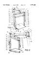
- FIG. 1is a perspective view of the multi-position television monitor stand, seen from the front.
- FIG. 2is a different perspective view of the object shown in FIG. 1, seen from behind.
- FIG. 3shows detail A from FIG. 1.
- FIG. 4shows detail B from FIG. 2.
- FIG. 5is a front elevation view of the invention shown in perspective in FIGS. 1 and 2.
- FIG. 6is a side elevation view of the invention shown in FIGS. 1 and 2.
- FIGS. 1-6clearly show how the multi-position television monitor stand 1 is supported by proper positioning of the larger surfaces of pieces 2 and 2', which have deep, concave depressions, to adjust and subsequently clamp it onto a vertical support 30.
- the pieces 2 and 2'are joined using conventional means, and their inside surfaces clamp vertically onto the external structure of the vertical support 30, as described.
- a U-shaped element 3extends out from the outside larger surface of the piece 2.
- the flanges of such U-shaped elementhave opposing bores, through which a pin with threaded ends passes and locks using conventional nuts, anchoring a parallelepiped extension 4 in the internal area of element 3, such that it extends horizontally from the point where pieces 2 and 2' have been previously anchored to the support 30 at a predetermined height, such that the monitor placed on the inner structure as described below can be comfortably viewed from a variety of positions.
- the extension 4is bored through at the end opposite the point where it is anchored to element 3.
- An anchoring element 7passes through such bore to attach a hollow, rectangular tubular element 6 to the extension 4, such that two tubular elements 8 and 8' can be inserted into its open ends.
- Such tubular elementsextend out from the inside surface of two elongated elements 9 and 9' at a 90° angle.
- the tubular extensions 8can be anchored inside element 6 using screws 21 and 21' to adjust the extensions or tubular elements 8 and 8' to the size of the television that is to be placed on a support or platform 19 as described below.
- the unit comprising pieces 9, 9', 8, 8' and 6has the general shape of an inverted "U" and is made of metal or a similar material, as are the other pieces constituting the multi-position stand 1.
- Arms 9 and 9'have two angled slots 16 and 16' at the bottom, with a circular area at the inside end of such slots.
- the "inverted-U" outer structure described aboveincorporates two hollow pieces 12 and 18.
- a rectangular piece 19 serving as a supporting platform for the monitor 50is attached on top of piece 18.
- Two tubular extensions 13 and 13'are inserted into the end openings of piece 12 and anchored to it in the desired position using screws 21 and 21'. Extensions 8 and 8' are inserted into the tubular element 6 in the same way.
- Extensions 13 and 13'are connected to two vertical tubular pieces 14 and 14' at a 90° angle.
- the outer surfaces of such tubular pieces 14 and 14'are provided with projections 17 and 17' and locking elements 15 and 15'.
- Inside such tubular pieces 14 and 14'is a mechanism that uses external screws 20 and 20' to control how far tubular elements 11 and 11' can be inserted into their bottom openings, thereby making it possible to accommodate a taller or shorter monitor 50 placed on the platform 19 attached to tubular element 18, which is held internally by extensions 10 and 10' at a 90° angle to pieces 11 and 11', by inserting pieces 11 and 11' into tubular elements 14 and 14'.
- the monitorcan be tilted at a variety of angles by moving the inner frame formed by tubular elements 12 and 18, extensions 13 and 13' attached to pieces 14 and 14', and connected tubular pieces 11 and 11', which are height-adjusted using the mechanism controlled by the screws or similar means 20 and 20' and are provided with extensions 10 inserted into tubular element 18, on top of which the platform 19 is attached.
Landscapes
- Engineering & Computer Science (AREA)
- General Engineering & Computer Science (AREA)
- Mechanical Engineering (AREA)
- Devices For Indicating Variable Information By Combining Individual Elements (AREA)
- Fittings On The Vehicle Exterior For Carrying Loads, And Devices For Holding Or Mounting Articles (AREA)
- Clamps And Clips (AREA)
Abstract
Description
1. Field of the Invention
This specification relates to an application for a utility model for The present invention relates to a multi-position television monitor stand, obviously intended to be used to position a television monitor, video monitor or similar device at a variety of angles. More specifically, the television monitor, video monitor or similar device is held within its support structure, which is in turn anchored to a vertical support using a clamping joint. A horizontal arm extends out from such joint and connects to the outer structure of the stand. Both the inner and outer structures are width- and height-adjustable to accommodate the monitor per se on the stand platform positioned on the middle cross-piece at the bottom of the inner structure.
The invention is intended for use within the industry devoted to the manufacture of equipment, devices and ancillary equipment for the television and telecommunications industry.
The multi-position television monitor stand covered by the invention constitutes in and of itself a substantial inventive step with respect to stands with fixed dimensions used for the same purpose, since this multi-position stand allows a single stand to be used for a variety of possible configurations, such that different monitor sizes can be adjusted to and perfectly accommodated on the stand, simply by adjusting the width and height of the various components of the stand itself.
In more tangible terms, the multi-position television monitor stand according to the invention comprises an element consisting of two identical pieces, which together form a parallelepiped with a central adjustment area extending lengthwise along the concave depressions on one of their larger surfaces, which can be adjusted to a vertical support with a circular section, and the piece perfectly clamped in place. A U-shaped element or plate with two bores in its flanges, into which a pin fastened using properly sized nuts is inserted, projects out from such piece. Such U-shaped element anchors a horizontal, parallelepiped extension that connects at its other end to an external structure or frame formed by the union of three elements incorporating a vertical anchoring element.
By varying the anchor point of the vertical support and the horizontal extension, the frame constituting the stand can move horizontally to point in various directions.
The outer frame comprises a middle element in the form of a hollow, rectangular tube. Two similar, but smaller tubular elements are introduced into the end opening of such middle element and slide inside it to adjust to the size of the monitor that will later be placed in the second frame.
Two flat plates extend from the outside ends of the tubes that slide inside the supporting element. Such plates have two angled slots near their lower end, which terminate in a circular area.
It is clear from the above that the outer frame has the shape of an inverted "U."
A second, four-cornered frame formed by two hollow, rectangular tubes is attached to the outer frame. The width of such second frame is adjusted to that of the larger structure or element by means of lateral endpieces extending out of vertical tubular elements.
Both the larger and the smaller, or inner, tubular elements, and the tubular element to which the monitor stand platform per se is attached, are anchored to the tubular elements that run inside them using conventional screws.
The lateral tubular elements have an internal longitudinal adjustment mechanism, whereby complementary tubular elements inserted into their lower end openings can be moved together or apart by operating the mechanism via adjustment heads on the top smaller surfaces of such elements.
Lateral extensions of the vertically sliding tubular elements are inserted horizontally into the tubular element supporting the monitor stand platform.
The entire structure described herein is made of metal.
The inner frame is attached to the outer frame via projections or lugs located on the outside, lateral surfaces of the vertical tubes containing the adjustment mechanism. Such projections or lugs are inserted into the angled slots and locked using external adjustment means.
The monitor in the stand can be tilted at a variety of angles by adjusting the width and height of the inner frame.
The invention is better understood by reading the following Detailed Description of the Preferred Embodiments with reference to the accompanying drawing figures, in which like reference numerals refer to like elements throughout, and in which:
FIG. 1 is a perspective view of the multi-position television monitor stand, seen from the front.
FIG. 2 is a different perspective view of the object shown in FIG. 1, seen from behind.
FIG. 3 shows detail A from FIG. 1.
FIG. 4 shows detail B from FIG. 2.
FIG. 5 is a front elevation view of the invention shown in perspective in FIGS. 1 and 2.
FIG. 6 is a side elevation view of the invention shown in FIGS. 1 and 2.
In describing preferred embodiments of the present invention illustrated in the drawings, specific terminology is employed for the sake of clarity. However, the invention is not intended to be limited to the specific terminology so selected, and it is to be understood that each specific element includes all technical equivalents which operate in a similar manner to accomplish a similar purpose.
FIGS. 1-6 clearly show how the multi-positiontelevision monitor stand 1 is supported by proper positioning of the larger surfaces ofpieces 2 and 2', which have deep, concave depressions, to adjust and subsequently clamp it onto avertical support 30. Thepieces 2 and 2' are joined using conventional means, and their inside surfaces clamp vertically onto the external structure of thevertical support 30, as described.
AU-shaped element 3 extends out from the outside larger surface of thepiece 2. The flanges of such U-shaped element have opposing bores, through which a pin with threaded ends passes and locks using conventional nuts, anchoring aparallelepiped extension 4 in the internal area ofelement 3, such that it extends horizontally from the point wherepieces 2 and 2' have been previously anchored to thesupport 30 at a predetermined height, such that the monitor placed on the inner structure as described below can be comfortably viewed from a variety of positions.
Theextension 4 is bored through at the end opposite the point where it is anchored toelement 3. Ananchoring element 7 passes through such bore to attach a hollow, rectangulartubular element 6 to theextension 4, such that twotubular elements 8 and 8' can be inserted into its open ends. Such tubular elements extend out from the inside surface of twoelongated elements 9 and 9' at a 90° angle. Thetubular extensions 8 can be anchored insideelement 6 usingscrews 21 and 21' to adjust the extensions ortubular elements 8 and 8' to the size of the television that is to be placed on a support orplatform 19 as described below.
Theunit comprising pieces multi-position stand 1.
These two angled slots onarms 9 and 9' are intended to accommodatelugs 17 and 17' andadjustable projections 15 and 15', to adjust the tilt angle of the inner structure as described below.
The "inverted-U" outer structure described above incorporates twohollow pieces rectangular piece 19 serving as a supporting platform for themonitor 50 is attached on top ofpiece 18.
Twotubular extensions 13 and 13' are inserted into the end openings ofpiece 12 and anchored to it in the desiredposition using screws 21 and 21'.Extensions 8 and 8' are inserted into thetubular element 6 in the same way.
Once the pieces have been properly assembled according to the dimensions of themonitor 50, as shown in FIG. 6 the monitor can be tilted at a variety of angles by moving the inner frame formed bytubular elements extensions 13 and 13' attached topieces 14 and 14', and connectedtubular pieces similar means 20 and 20' and are provided withextensions 10 inserted intotubular element 18, on top of which theplatform 19 is attached.
Modifications and variations of the above-described embodiments of the present invention are possible, as appreciated by those skilled in the art in light of the above teachings. It is therefore to be understood that, within the scope of the appended claims and their equivalents, the invention may be practiced otherwise than as specifically described.
Claims (7)
1. A multi-position television monitor stand, comprising:
a vertical support having a convex outer surface;
a first pin having a longitudinal axis;
a second pin having a longitudinal axis parallel to the longitudinal axis of the first pin;
first and second pieces each having a rectangular footprint, an inner surface, and an outer surface opposite the inner surface, the inner surface of the first piece having a deep, semicircular, concave depression to mate with the outer surface of the vertical support, the outer surface of the second piece having a U-shaped projection which is bored through to accommodate the first pin;
a hollow element projecting from the second piece, the hollow element having a first end held on the second piece by the first pin and a second end opposite the first end;
a first transverse tubular element having a bore therethrough and first and second opposite ends, the second pin being inserted through the bore to connect the first transverse tubular element to the second end of the hollow element;
first and second horizontal tubular extensions inserted into the first and second ends, respectively, of the first transverse tubular element and fixed at a predetermined distance;
first and second vertical plates extending out from the first and second horizontal tubular extensions, respectively, at a 90° angle, the first and second vertical plates each having two angled slots having a circular area at their inside end;
first and second vertical tubular elements having upper and lower ends, and outside surface with lugs and projections with tightening joints, the angled slots accommodating the lugs and the projections with tightening joints;
third and fourth horizontal tubular extensions extending at a 90° angle from the upper ends of the first and second vertical tubular elements, respectively; and
a second transverse tubular element parallel to and downwardly offset from the first transverse tubular element, the third and fourth horizontal tubular extensions being inserted into the second transverse tubular element and fixed to extend at a predetermined distance from the ends of the second transverse tubular element.
2. A multi-position television monitor stand as claimed in claim 1, further comprising:
third and fourth vertical tubular elements inserted respectively in the first and second vertical tubular elements, the first and second vertical tubular elements including internal mechanisms for controlling the positions of the third and fourth vertical tubular elements relative to the first and second vertical tubular elements, and
pieces projecting from the upper ends of the first and second vertical tubular elements for operating the internal mechanisms from the exterior of the first and second vertical tubular elements.
3. A multi-position television monitor stand as claimed in claim 2, further comprising:
fifth and sixth horizontal tubular extensions extending inwardly from said third and fourth vertical tubular elements, respectively, at a 90° angle;
a third transverse tubular element having first and second ends and a top surface, the fifth and sixth horizontal tubular extensions being inserted into the first and second ends, respectively, of the third transverse tubular element and fixed extending outwardly from the first and second ends of the third transverse tubular element at a predetermined distance using screws; and
a horizontal plate attached to the top surface of the third transverse tubular element.
4. A multi-position television monitor stand as claimed in claim 3, wherein;
the union of the second and third transverse tubular elements with the first, second, third, and fourth vertical tubular elements via the third, fourth, fifth, and sixth horizontal tubular extensions defines a rectangular inner frame which supports the horizontal plate and which can be tilted at a variety of angles depending on how the tightening joints are adjusted on the first and second vertical plates.
5. A multi-position television monitor stand as claimed in claim 1, further comprising:
third and fourth vertical tubular elements inserted respectively in the first and second vertical tubular elements;
fifth and sixth horizontal tubular extensions extending inwardly from said third and fourth vertical tubular elements, respectively, at a 90° angle;
a third transverse tubular element having first and second ends and a top surface, the fifth and sixth horizontal tubular extensions being inserted into the first and second ends, respectively, of the third transverse tubular element and fixed extending outwardly from the first and second ends of the third transverse tubular element at a predetermined distance using screws; and
a horizontal plate attached to the top surface of the third transverse tubular element.
6. A multi-position television monitor stand as claimed in claim 5, wherein;
the union of the second and third transverse tubular elements with the first, second, third, and fourth vertical tubular elements via the third, fourth, fifth, and sixth horizontal tubular extensions defines a rectangular inner frame which supports the horizontal plate and which can be tilted at a variety of angles depending on how the tightening joints are adjusted on the first and second vertical plates.
7. A multi-position television monitor stand as claimed in claim 1, wherein:
the first and second pieces constitute a clamping joint that is adjustable to be at one of plural vertical locations on the vertical support, whereby the television monitor stand is rendered vertically adjustable.
Applications Claiming Priority (2)
| Application Number | Priority Date | Filing Date | Title |
|---|---|---|---|
| ES9601480 | 1996-05-30 | ||
| ES09601480UES1034279U (en) | 1996-05-30 | 1996-05-30 | Multi-position television monitor stand |
Publications (1)
| Publication Number | Publication Date |
|---|---|
| US5797568Atrue US5797568A (en) | 1998-08-25 |
Family
ID=8295366
Family Applications (1)
| Application Number | Title | Priority Date | Filing Date |
|---|---|---|---|
| US08/751,489Expired - Fee RelatedUS5797568A (en) | 1996-05-30 | 1996-11-18 | Multi-position television monitor stand |
Country Status (6)
| Country | Link |
|---|---|
| US (1) | US5797568A (en) |
| AR (1) | AR004615A4 (en) |
| CU (1) | CU22567A3 (en) |
| ES (1) | ES1034279U (en) |
| PE (1) | PE30997Z (en) |
| PT (1) | PT9336U (en) |
Cited By (67)
| Publication number | Priority date | Publication date | Assignee | Title |
|---|---|---|---|---|
| US5988571A (en)* | 1997-09-22 | 1999-11-23 | Ward; Glenn F. | TV/VCR mount |
| US6068227A (en)* | 1997-03-11 | 2000-05-30 | Pixelvision Technology, Inc. | Flat panel display housing |
| USD430166S (en)* | 1998-09-29 | 2000-08-29 | Sony Corporation | Stand for monitor |
| US6113047A (en)* | 1997-12-15 | 2000-09-05 | Intermec Technologies Corporation | Dual point vehicle mount for computer terminal |
| US6158708A (en)* | 1997-08-08 | 2000-12-12 | Siemens Medical Systems, Inc. | Rotational flatness improvement |
| US6213481B1 (en)* | 1998-07-01 | 2001-04-10 | Alm | Assembly consisting of a support structure and of a trolley for transporting equipment |
| GB2358345A (en)* | 2000-01-20 | 2001-07-25 | Foued Ghidaoui | Adjustable support arm |
| GB2360894A (en)* | 2000-03-30 | 2001-10-03 | Peter Thomas Bosson | Display device support system |
| FR2821901A1 (en)* | 2001-03-12 | 2002-09-13 | Id Ind & Design | DEVICE FOR SUPPORTING A FLAT SCREEN WITH LIQUID CRYSTALS |
| US20030047657A1 (en)* | 2000-03-17 | 2003-03-13 | Markus Neuhof | Lug system |
| US6581887B2 (en)* | 2001-11-19 | 2003-06-24 | Mark R Lapidez | Rotatable television mounting assembly |
| US20040011935A1 (en)* | 2002-01-25 | 2004-01-22 | Groesen Wilhelmus Maria Van | Device suitable for connection thereto of a component, such as a flat panel display screen, as well as a carrier suitable for use with such a device |
| US20040041062A1 (en)* | 2002-09-03 | 2004-03-04 | Ozolins Helmars E. | Support for one or more flat panel displays |
| US20040104318A1 (en)* | 2002-12-03 | 2004-06-03 | Oliveira Filho Gilberto Goncalves | Constructive arrangement introduced in a wall support for television set and other appliances |
| US6783105B2 (en) | 2001-06-20 | 2004-08-31 | Innovative Office Products, Inc. | Adjustable display arm for computer components |
| EP1465007A1 (en)* | 2003-04-04 | 2004-10-06 | Pony Ma | Anchoring device for anchoring a camera monitor on a camera stand |
| US20040232301A1 (en)* | 2003-04-11 | 2004-11-25 | Jeff Bremmon | Adaptable mounting system for flat panel display |
| US20050061931A1 (en)* | 2003-07-17 | 2005-03-24 | Innovative Office Products, Inc. | Adjustable display arm for electronic components |
| US20050092885A1 (en)* | 2003-10-30 | 2005-05-05 | Benq Corporation | Automatic support mechanism and use thereof |
| US20050121577A1 (en)* | 2003-12-04 | 2005-06-09 | Innovative Office Products, Inc. | Universal wall mounting bracket |
| US20050139742A1 (en)* | 2002-02-08 | 2005-06-30 | Erik Frisell | Column |
| US20060022096A1 (en)* | 2004-07-28 | 2006-02-02 | Chin-Chung Chan | Multi-functional adjustable computer support stand |
| US7077373B1 (en)* | 2000-01-05 | 2006-07-18 | Da-Lite Screen Co., Inc. | Mount for TV monitor |
| WO2006047784A3 (en)* | 2004-10-26 | 2006-08-03 | Steelworks Hardware Llc | A tool box fastening device for fastening a tool box set to a vertical wall |
| US20060250347A1 (en)* | 2004-01-08 | 2006-11-09 | Bell'o International, L.L.C. | Flat panel display mounting system |
| US20060249641A1 (en)* | 2005-05-06 | 2006-11-09 | Steris Inc. | Transfer system and transfer device |
| USD541138S1 (en)* | 2005-04-18 | 2007-04-24 | Whalen Furniture Manufacturing Inc. | Television bracket |
| US20070181762A1 (en)* | 2002-06-11 | 2007-08-09 | Jay Dittmer | Adjustable self-balancing flat panel display mounting system |
| US20070194196A1 (en)* | 2003-01-09 | 2007-08-23 | Csav, Inc. | Adjustable tilt mount |
| US20070221807A1 (en)* | 2006-03-22 | 2007-09-27 | Samsung Electronics Co., Ltd. | Supporting device of display unit |
| US7377475B1 (en)* | 2005-07-22 | 2008-05-27 | Rodovaldo Lopez | Television mount assembly |
| US20090032665A1 (en)* | 2007-07-30 | 2009-02-05 | Smith Jr William Riley | Overhead mounting apparatus |
| US20090065669A1 (en)* | 2007-09-12 | 2009-03-12 | Jin Elkins | Pole mounting systems and methods |
| US20090114792A1 (en)* | 2007-11-06 | 2009-05-07 | Hitachi, Ltd. | Image Display Apparatus |
| US20090243447A1 (en)* | 2006-05-17 | 2009-10-01 | Ernestomeda S.P.A. | Rotary Piece of Furniture |
| US7641163B2 (en) | 2005-10-21 | 2010-01-05 | Peerless Industries, Inc. | Tilt mounting system |
| US7738245B1 (en)* | 2009-11-23 | 2010-06-15 | Peerless Industries, Inc. | Display mount |
| US20100148647A1 (en)* | 2008-12-11 | 2010-06-17 | Rubbermaid Incorporated | Wall work station |
| USD620943S1 (en) | 2009-01-07 | 2010-08-03 | Milestone Av Technologies Llc | Single arm display mount |
| USD627787S1 (en) | 2009-01-07 | 2010-11-23 | Milestone Av Technologies Llc | Display mount with single articulating arm |
| US20100314515A1 (en)* | 2009-06-13 | 2010-12-16 | C&G Venture Group Llc | Adjustable electronic device holder |
| US7866622B2 (en) | 2007-01-05 | 2011-01-11 | Milestone Av Technologies Llc | In-wall mount |
| US7891622B1 (en) | 2007-02-02 | 2011-02-22 | Peerless Industries, Inc. | Adjustable tilt mounting system |
| US20110233350A1 (en)* | 2010-01-29 | 2011-09-29 | Rubbermaid Incorporated | Work station with height adjustment lock |
| US20110235249A1 (en)* | 2010-01-29 | 2011-09-29 | Rubbermaid Incorporated | Work surface articulation |
| US20110235250A1 (en)* | 2010-01-29 | 2011-09-29 | Rubbermaid Incorporated | Keyboard tray tilt |
| US8072739B2 (en) | 2007-01-03 | 2011-12-06 | Milestone Av Technologies Llc | Device mount with selectively positionable tilt axis |
| US8094438B2 (en) | 2007-01-05 | 2012-01-10 | Milestone Av Technologies Llc | Wall-avoiding self-balancing mount for tilt positioning of a flat panel electronic display |
| US20120114500A1 (en)* | 2010-11-05 | 2012-05-10 | Hon Hai Precision Industry Co., Ltd. | Fan holder and heat dissipation device using the same |
| US20120240471A1 (en)* | 2011-03-25 | 2012-09-27 | Baltimore Aircoil Company, Inc. | Cooling tower entry door structure |
| US20120285908A1 (en)* | 2008-07-14 | 2012-11-15 | United Parcel Service Of America, Inc. | Cathode ray tube monitor to flat panel monitor conversion bracket |
| CN103247214A (en)* | 2013-03-21 | 2013-08-14 | 柳州铁道职业技术学院 | Multifunctional teaching rack for electronic-controlled engine |
| US8662605B2 (en) | 2011-02-18 | 2014-03-04 | Rubbermaid Incorporated | Mobile technology cabinet |
| US8677911B2 (en) | 2011-02-18 | 2014-03-25 | Rubbermaid Incorporated | Technology cart |
| US8794579B2 (en) | 2005-06-03 | 2014-08-05 | Steelcase, Inc. | Support arm assembly |
| US8891249B2 (en) | 2009-01-07 | 2014-11-18 | Milestone Av Technologies Llc | Display mount with adjustable position tilt axis |
| CN104536523A (en)* | 2014-12-23 | 2015-04-22 | 重庆宝丽佰格电子科技有限公司 | Liftable computer displayer |
| CN104565721A (en)* | 2014-12-23 | 2015-04-29 | 重庆宝丽佰格电子科技有限公司 | Display supporting seat |
| US9109742B2 (en) | 2008-09-02 | 2015-08-18 | Milestone Av Technologies Llc | Low profile mount for flat panel electronic display |
| US9265346B1 (en)* | 2015-03-13 | 2016-02-23 | Anthony Eugene Forney | Responsive support system and mount |
| US20160302325A1 (en)* | 2012-09-14 | 2016-10-13 | Hoffman Enclosures, Inc. | Center Pivot Swing-Out Wall Rack |
| US9848698B2 (en)* | 2015-08-11 | 2017-12-26 | International Gaming Projects Limited | Display and enclosure apparatus |
| US9933106B2 (en) | 2013-03-14 | 2018-04-03 | Capsa Solutions, Llc | Height adjustable support |
| CN109159938A (en)* | 2018-09-30 | 2019-01-08 | 刘培珠 | A kind of packing device turned on one's side when television set being avoided to pack |
| US20190309894A1 (en)* | 2016-12-28 | 2019-10-10 | Panasonic Intellectual Property Management Co., Ltd. | Display device and stand set |
| CN112013238A (en)* | 2020-07-30 | 2020-12-01 | 烟台南山学院 | Computer information management collection system |
| CN113653907A (en)* | 2021-08-24 | 2021-11-16 | 南阳理工学院 | A multi-environment adaptable outdoor publicity device |
Citations (11)
| Publication number | Priority date | Publication date | Assignee | Title |
|---|---|---|---|---|
| US2299218A (en)* | 1941-11-24 | 1942-10-20 | Fener Alfred | Adjustable dipole antenna unit |
| US4516751A (en)* | 1982-09-17 | 1985-05-14 | Charles Westbrook | Wall bracket system |
| US4575063A (en)* | 1982-10-13 | 1986-03-11 | Schlegel Gmbh | Vertically adjustable device |
| US4836478A (en)* | 1987-10-15 | 1989-06-06 | Ergotron, Inc. | Suspension system for personal computers and monitors |
| US4884420A (en)* | 1986-02-24 | 1989-12-05 | Dennis E. McGoldrick, Trustee | Cage with floating nut assembly |
| US4946123A (en)* | 1988-08-04 | 1990-08-07 | Albert Rino P | Roof bracket |
| US4964606A (en)* | 1989-10-26 | 1990-10-23 | Ncr Corporation | Overhead mount for a CRT |
| US4993676A (en)* | 1990-01-16 | 1991-02-19 | Fitts William E | Apparatus for supporting a television set from a ceiling |
| US5139223A (en)* | 1991-04-09 | 1992-08-18 | Marty Sedighzadeh | Wall/ceiling support for television monitor |
| US5393025A (en)* | 1993-10-21 | 1995-02-28 | Franklin; Harry C. | Cabinet mounting harness |
| US5400993A (en)* | 1993-08-17 | 1995-03-28 | Hamilton; Clifton | Adjustable overhead suspension apparatus for TV and VCR |
- 1996
- 1996-05-30ESES09601480Upatent/ES1034279U/ennot_activeWithdrawn
- 1996-11-12PEPE1996000808Upatent/PE30997Z/ennot_activeIP Right Cessation
- 1996-11-12CUCU1996099Apatent/CU22567A3/enunknown
- 1996-11-18ARARM960105232Upatent/AR004615A4/enunknown
- 1996-11-18USUS08/751,489patent/US5797568A/ennot_activeExpired - Fee Related
- 1996-11-25PTPT9336Upatent/PT9336U/ennot_activeIP Right Cessation
Patent Citations (11)
| Publication number | Priority date | Publication date | Assignee | Title |
|---|---|---|---|---|
| US2299218A (en)* | 1941-11-24 | 1942-10-20 | Fener Alfred | Adjustable dipole antenna unit |
| US4516751A (en)* | 1982-09-17 | 1985-05-14 | Charles Westbrook | Wall bracket system |
| US4575063A (en)* | 1982-10-13 | 1986-03-11 | Schlegel Gmbh | Vertically adjustable device |
| US4884420A (en)* | 1986-02-24 | 1989-12-05 | Dennis E. McGoldrick, Trustee | Cage with floating nut assembly |
| US4836478A (en)* | 1987-10-15 | 1989-06-06 | Ergotron, Inc. | Suspension system for personal computers and monitors |
| US4946123A (en)* | 1988-08-04 | 1990-08-07 | Albert Rino P | Roof bracket |
| US4964606A (en)* | 1989-10-26 | 1990-10-23 | Ncr Corporation | Overhead mount for a CRT |
| US4993676A (en)* | 1990-01-16 | 1991-02-19 | Fitts William E | Apparatus for supporting a television set from a ceiling |
| US5139223A (en)* | 1991-04-09 | 1992-08-18 | Marty Sedighzadeh | Wall/ceiling support for television monitor |
| US5400993A (en)* | 1993-08-17 | 1995-03-28 | Hamilton; Clifton | Adjustable overhead suspension apparatus for TV and VCR |
| US5393025A (en)* | 1993-10-21 | 1995-02-28 | Franklin; Harry C. | Cabinet mounting harness |
Cited By (108)
| Publication number | Priority date | Publication date | Assignee | Title |
|---|---|---|---|---|
| US6068227A (en)* | 1997-03-11 | 2000-05-30 | Pixelvision Technology, Inc. | Flat panel display housing |
| US6158708A (en)* | 1997-08-08 | 2000-12-12 | Siemens Medical Systems, Inc. | Rotational flatness improvement |
| US5988571A (en)* | 1997-09-22 | 1999-11-23 | Ward; Glenn F. | TV/VCR mount |
| US6113047A (en)* | 1997-12-15 | 2000-09-05 | Intermec Technologies Corporation | Dual point vehicle mount for computer terminal |
| US6213481B1 (en)* | 1998-07-01 | 2001-04-10 | Alm | Assembly consisting of a support structure and of a trolley for transporting equipment |
| USD430166S (en)* | 1998-09-29 | 2000-08-29 | Sony Corporation | Stand for monitor |
| US7077373B1 (en)* | 2000-01-05 | 2006-07-18 | Da-Lite Screen Co., Inc. | Mount for TV monitor |
| GB2358345A (en)* | 2000-01-20 | 2001-07-25 | Foued Ghidaoui | Adjustable support arm |
| GB2358345B (en)* | 2000-01-20 | 2002-04-03 | Foued Ghidaoui | Adjustable supporting arm arrangement |
| US20030047657A1 (en)* | 2000-03-17 | 2003-03-13 | Markus Neuhof | Lug system |
| US6695265B2 (en)* | 2000-03-17 | 2004-02-24 | Rittal Gmbh & Co. Kg | Lug system |
| GB2360894B (en)* | 2000-03-30 | 2004-11-10 | Peter Thomas Bosson | Display device support system |
| US6863252B2 (en) | 2000-03-30 | 2005-03-08 | Peter Thomas Bosson | Display device support system |
| GB2360894A (en)* | 2000-03-30 | 2001-10-03 | Peter Thomas Bosson | Display device support system |
| USRE44727E1 (en)* | 2000-03-30 | 2014-01-28 | Colebrook Bosson & Saunders (Products) Limited | Display device support system |
| US20020011544A1 (en)* | 2000-03-30 | 2002-01-31 | Bosson Peter Thomas | Display device support system |
| FR2821901A1 (en)* | 2001-03-12 | 2002-09-13 | Id Ind & Design | DEVICE FOR SUPPORTING A FLAT SCREEN WITH LIQUID CRYSTALS |
| US20040079858A1 (en)* | 2001-03-12 | 2004-04-29 | Alain Rudolf | Support device for liquid crystal flat screen |
| WO2002073085A1 (en)* | 2001-03-12 | 2002-09-19 | Id - Industrie + Design | Support device for liquid crystal flat screen |
| US6783105B2 (en) | 2001-06-20 | 2004-08-31 | Innovative Office Products, Inc. | Adjustable display arm for computer components |
| US6581887B2 (en)* | 2001-11-19 | 2003-06-24 | Mark R Lapidez | Rotatable television mounting assembly |
| US20040011935A1 (en)* | 2002-01-25 | 2004-01-22 | Groesen Wilhelmus Maria Van | Device suitable for connection thereto of a component, such as a flat panel display screen, as well as a carrier suitable for use with such a device |
| US20050139742A1 (en)* | 2002-02-08 | 2005-06-30 | Erik Frisell | Column |
| US8490934B2 (en) | 2002-06-11 | 2013-07-23 | Milestone Av Technologies Llc | Adjustable, self-balancing flat panel display mounting system |
| US7954780B2 (en) | 2002-06-11 | 2011-06-07 | Milestone Av Technologies Llc | Adjustable self-balancing flat panel display mounting system |
| US7395996B2 (en) | 2002-06-11 | 2008-07-08 | Csav, Inc. | Adjustable, self-balancing flat panel display mounting system |
| US20070181762A1 (en)* | 2002-06-11 | 2007-08-09 | Jay Dittmer | Adjustable self-balancing flat panel display mounting system |
| US7607620B2 (en)* | 2002-09-03 | 2009-10-27 | Bloomberg Finance L.P. | Support for one or more flat panel displays |
| US20040041062A1 (en)* | 2002-09-03 | 2004-03-04 | Ozolins Helmars E. | Support for one or more flat panel displays |
| US20040104318A1 (en)* | 2002-12-03 | 2004-06-03 | Oliveira Filho Gilberto Goncalves | Constructive arrangement introduced in a wall support for television set and other appliances |
| US20070194196A1 (en)* | 2003-01-09 | 2007-08-23 | Csav, Inc. | Adjustable tilt mount |
| US7438269B2 (en) | 2003-01-09 | 2008-10-21 | Csav, Inc. | Adjustable tilt mount |
| US8235342B2 (en) | 2003-01-09 | 2012-08-07 | Milestone AV Techonologies LLC | Adjustable tilt mount |
| EP1465007A1 (en)* | 2003-04-04 | 2004-10-06 | Pony Ma | Anchoring device for anchoring a camera monitor on a camera stand |
| US20040232301A1 (en)* | 2003-04-11 | 2004-11-25 | Jeff Bremmon | Adaptable mounting system for flat panel display |
| US7222831B2 (en) | 2003-07-17 | 2007-05-29 | Innovative Office Products, Inc. | Adjustable display arm for electronic components |
| US20050061931A1 (en)* | 2003-07-17 | 2005-03-24 | Innovative Office Products, Inc. | Adjustable display arm for electronic components |
| US20050092885A1 (en)* | 2003-10-30 | 2005-05-05 | Benq Corporation | Automatic support mechanism and use thereof |
| US7395991B2 (en)* | 2003-10-30 | 2008-07-08 | Qisda Corporation | Automatic support mechanism and use thereof |
| US7066435B2 (en) | 2003-12-04 | 2006-06-27 | Innovation Office Products, Inc. | Universal wall mounting bracket |
| US20050121577A1 (en)* | 2003-12-04 | 2005-06-09 | Innovative Office Products, Inc. | Universal wall mounting bracket |
| US20060250347A1 (en)* | 2004-01-08 | 2006-11-09 | Bell'o International, L.L.C. | Flat panel display mounting system |
| US7118080B2 (en)* | 2004-07-28 | 2006-10-10 | Chin-Chung Chan | Multi-functional adjustable computer support stand |
| US20060022096A1 (en)* | 2004-07-28 | 2006-02-02 | Chin-Chung Chan | Multi-functional adjustable computer support stand |
| US20070102381A1 (en)* | 2004-10-26 | 2007-05-10 | Chanwa Nguy | Tool box fastening device for fastening a tool box set to a vertical wall |
| WO2006047784A3 (en)* | 2004-10-26 | 2006-08-03 | Steelworks Hardware Llc | A tool box fastening device for fastening a tool box set to a vertical wall |
| US8061536B2 (en) | 2004-10-26 | 2011-11-22 | Steelworks Hardware, Llc | Tool box fastening device for fastening a tool box set to a vertical wall |
| USD541138S1 (en)* | 2005-04-18 | 2007-04-24 | Whalen Furniture Manufacturing Inc. | Television bracket |
| US20060249641A1 (en)* | 2005-05-06 | 2006-11-09 | Steris Inc. | Transfer system and transfer device |
| US7789361B2 (en) | 2005-05-06 | 2010-09-07 | American Sterilizer Company | Transfer system and transfer device |
| US8794579B2 (en) | 2005-06-03 | 2014-08-05 | Steelcase, Inc. | Support arm assembly |
| US7377475B1 (en)* | 2005-07-22 | 2008-05-27 | Rodovaldo Lopez | Television mount assembly |
| US7753332B2 (en) | 2005-10-21 | 2010-07-13 | Peerless Industries, Inc. | Tilt mounting system |
| US8313073B2 (en) | 2005-10-21 | 2012-11-20 | Peerless Industries, Inc. | Tilt mounting system |
| US8157233B2 (en) | 2005-10-21 | 2012-04-17 | Peerless Industries, Inc. | Tilt mounting system |
| US8684326B2 (en) | 2005-10-21 | 2014-04-01 | Peerless Industries, Inc. | Tilt mounting system |
| US7641163B2 (en) | 2005-10-21 | 2010-01-05 | Peerless Industries, Inc. | Tilt mounting system |
| US20070221807A1 (en)* | 2006-03-22 | 2007-09-27 | Samsung Electronics Co., Ltd. | Supporting device of display unit |
| US7984888B2 (en)* | 2006-03-22 | 2011-07-26 | Samsung Electronics Co., Ltd. | Supporting device of a display unit capable of horizontal and vertical rotation |
| US20090243447A1 (en)* | 2006-05-17 | 2009-10-01 | Ernestomeda S.P.A. | Rotary Piece of Furniture |
| US8072739B2 (en) | 2007-01-03 | 2011-12-06 | Milestone Av Technologies Llc | Device mount with selectively positionable tilt axis |
| US7866622B2 (en) | 2007-01-05 | 2011-01-11 | Milestone Av Technologies Llc | In-wall mount |
| US8094438B2 (en) | 2007-01-05 | 2012-01-10 | Milestone Av Technologies Llc | Wall-avoiding self-balancing mount for tilt positioning of a flat panel electronic display |
| US8508918B2 (en) | 2007-01-05 | 2013-08-13 | Milestone Av Technologies Llc | Wall-avoiding self-balancing mount for tilt positioning of a flat panel electronic display |
| US7891622B1 (en) | 2007-02-02 | 2011-02-22 | Peerless Industries, Inc. | Adjustable tilt mounting system |
| US20090032665A1 (en)* | 2007-07-30 | 2009-02-05 | Smith Jr William Riley | Overhead mounting apparatus |
| US20090065669A1 (en)* | 2007-09-12 | 2009-03-12 | Jin Elkins | Pole mounting systems and methods |
| US8066234B2 (en)* | 2007-11-06 | 2011-11-29 | Hitachi, Ltd. | Image display apparatus |
| US20090114792A1 (en)* | 2007-11-06 | 2009-05-07 | Hitachi, Ltd. | Image Display Apparatus |
| US20120285908A1 (en)* | 2008-07-14 | 2012-11-15 | United Parcel Service Of America, Inc. | Cathode ray tube monitor to flat panel monitor conversion bracket |
| US8827217B2 (en)* | 2008-07-14 | 2014-09-09 | United Parcel Service Of America, Inc. | Cathode ray tube monitor to flat panel monitor conversion bracket |
| US9109742B2 (en) | 2008-09-02 | 2015-08-18 | Milestone Av Technologies Llc | Low profile mount for flat panel electronic display |
| US8905496B2 (en) | 2008-12-11 | 2014-12-09 | Rubbermaid Incorporated | Wall work station |
| US20100148647A1 (en)* | 2008-12-11 | 2010-06-17 | Rubbermaid Incorporated | Wall work station |
| US10051956B2 (en) | 2008-12-11 | 2018-08-21 | Capsa Solutions, Llc | Wall work station |
| US8891249B2 (en) | 2009-01-07 | 2014-11-18 | Milestone Av Technologies Llc | Display mount with adjustable position tilt axis |
| USD620943S1 (en) | 2009-01-07 | 2010-08-03 | Milestone Av Technologies Llc | Single arm display mount |
| USD627787S1 (en) | 2009-01-07 | 2010-11-23 | Milestone Av Technologies Llc | Display mount with single articulating arm |
| US7988114B2 (en)* | 2009-06-13 | 2011-08-02 | Coleman Joseph C | Adjustable electronic device holder |
| US20100314515A1 (en)* | 2009-06-13 | 2010-12-16 | C&G Venture Group Llc | Adjustable electronic device holder |
| US7738245B1 (en)* | 2009-11-23 | 2010-06-15 | Peerless Industries, Inc. | Display mount |
| US20110121151A1 (en)* | 2009-11-23 | 2011-05-26 | Peerless Industries, Inc. | Display mount |
| US7952863B1 (en) | 2009-11-23 | 2011-05-31 | Peerless Industries, Inc. | Display mount |
| US20110233350A1 (en)* | 2010-01-29 | 2011-09-29 | Rubbermaid Incorporated | Work station with height adjustment lock |
| US20110235250A1 (en)* | 2010-01-29 | 2011-09-29 | Rubbermaid Incorporated | Keyboard tray tilt |
| US20110235249A1 (en)* | 2010-01-29 | 2011-09-29 | Rubbermaid Incorporated | Work surface articulation |
| US8567735B2 (en) | 2010-01-29 | 2013-10-29 | Rubbermaid Incorporated | Work station with height adjustment lock |
| US8616136B2 (en) | 2010-01-29 | 2013-12-31 | Rubbermaid Incorporated | Keyboard tray tilt |
| US8613595B2 (en)* | 2010-11-05 | 2013-12-24 | Hong Fu Jin Precision Industry (Shenzhen) Co., Ltd | Fan holder and heat dissipation device using the same |
| US20120114500A1 (en)* | 2010-11-05 | 2012-05-10 | Hon Hai Precision Industry Co., Ltd. | Fan holder and heat dissipation device using the same |
| US8677911B2 (en) | 2011-02-18 | 2014-03-25 | Rubbermaid Incorporated | Technology cart |
| US8662605B2 (en) | 2011-02-18 | 2014-03-04 | Rubbermaid Incorporated | Mobile technology cabinet |
| US8683749B2 (en)* | 2011-03-25 | 2014-04-01 | Baltimore Aircoil Company, Inc. | Cooling tower entry door structure |
| US20120240471A1 (en)* | 2011-03-25 | 2012-09-27 | Baltimore Aircoil Company, Inc. | Cooling tower entry door structure |
| US20160302325A1 (en)* | 2012-09-14 | 2016-10-13 | Hoffman Enclosures, Inc. | Center Pivot Swing-Out Wall Rack |
| US9933106B2 (en) | 2013-03-14 | 2018-04-03 | Capsa Solutions, Llc | Height adjustable support |
| CN103247214A (en)* | 2013-03-21 | 2013-08-14 | 柳州铁道职业技术学院 | Multifunctional teaching rack for electronic-controlled engine |
| CN103247214B (en)* | 2013-03-21 | 2015-08-05 | 柳州铁道职业技术学院 | Electric-control motor multifunction teaching stand |
| CN104536523A (en)* | 2014-12-23 | 2015-04-22 | 重庆宝丽佰格电子科技有限公司 | Liftable computer displayer |
| CN104565721A (en)* | 2014-12-23 | 2015-04-29 | 重庆宝丽佰格电子科技有限公司 | Display supporting seat |
| US9265346B1 (en)* | 2015-03-13 | 2016-02-23 | Anthony Eugene Forney | Responsive support system and mount |
| US9848698B2 (en)* | 2015-08-11 | 2017-12-26 | International Gaming Projects Limited | Display and enclosure apparatus |
| US20190309894A1 (en)* | 2016-12-28 | 2019-10-10 | Panasonic Intellectual Property Management Co., Ltd. | Display device and stand set |
| US10844996B2 (en)* | 2016-12-28 | 2020-11-24 | Panasonic Intellectual Property Management Co., Ltd. | Display device and stand set |
| CN109159938A (en)* | 2018-09-30 | 2019-01-08 | 刘培珠 | A kind of packing device turned on one's side when television set being avoided to pack |
| CN112013238A (en)* | 2020-07-30 | 2020-12-01 | 烟台南山学院 | Computer information management collection system |
| CN113653907A (en)* | 2021-08-24 | 2021-11-16 | 南阳理工学院 | A multi-environment adaptable outdoor publicity device |
| CN113653907B (en)* | 2021-08-24 | 2022-10-04 | 南阳理工学院 | Outdoor propaganda device of multi-environment adaptability |
Also Published As
| Publication number | Publication date |
|---|---|
| CU22567A3 (en) | 1999-08-03 |
| PT9336T (en) | 1997-12-31 |
| AR004615A4 (en) | 1998-12-16 |
| PE30997Z (en) | 1997-09-05 |
| ES1034279U (en) | 1996-12-16 |
| PT9336U (en) | 1999-03-31 |
Similar Documents
| Publication | Publication Date | Title |
|---|---|---|
| US5797568A (en) | Multi-position television monitor stand | |
| US7077373B1 (en) | Mount for TV monitor | |
| US7331551B2 (en) | Multiple electronic device reorienting support | |
| US4579436A (en) | Tripod for mounting film and television cameras etc. | |
| US5165644A (en) | Mounting apparatus for a video display | |
| US5884874A (en) | Swivel post anchor | |
| US20070068019A1 (en) | Measuring apparatus | |
| US6349869B1 (en) | Welding clamp | |
| US5870858A (en) | Christmas tree stand | |
| US7712710B2 (en) | Telescoping stand with pivoting head | |
| GB2230946A (en) | Adjustable CRT support stand | |
| JP2005521843A (en) | Tripods for the support of devices in general, especially optical devices or photographic devices | |
| CN100554881C (en) | Spirit-leveling instrument | |
| EP0665933A1 (en) | Stand and accessory for stand | |
| JPWO2004081652A1 (en) | Panorama shooting support device | |
| US5632459A (en) | Angle head tripod | |
| US5871186A (en) | Support device | |
| AU2003259611B2 (en) | Channel device | |
| US7390131B2 (en) | Decoupled weight compensation system for a camera balance-device | |
| US4958793A (en) | Stanchion | |
| US20070007702A1 (en) | Device and arrangement for fixing workpieces | |
| JP3504615B2 (en) | Improvements in or related to tiltable mounts for TV cameras | |
| AU2001285913A1 (en) | Support for a microtiter plate | |
| US6164017A (en) | Adjustable linkage | |
| JPH08302632A (en) | Handrail fence |
Legal Events
| Date | Code | Title | Description |
|---|---|---|---|
| AS | Assignment | Owner name:TELEFONICA DE ESPANA S.A., SPAIN Free format text:ASSIGNMENT OF ASSIGNORS INTEREST;ASSIGNORS:CANTON GONGORA, ANTONIO;CRUZ FERNANDEZ, CARLOS JESUS;MUNAGORRI ENRIQUEZ, JOSE MARIA;AND OTHERS;REEL/FRAME:008417/0054 Effective date:19970224 | |
| AS | Assignment | Owner name:TELEFONICA, S.A., SPAIN Free format text:CHANGE OF NAME;ASSIGNOR:TELEFONICA DE ESPANA, S.A.;REEL/FRAME:010841/0391 Effective date:19980415 | |
| REMI | Maintenance fee reminder mailed | ||
| LAPS | Lapse for failure to pay maintenance fees | ||
| STCH | Information on status: patent discontinuation | Free format text:PATENT EXPIRED DUE TO NONPAYMENT OF MAINTENANCE FEES UNDER 37 CFR 1.362 | |
| FP | Lapsed due to failure to pay maintenance fee | Effective date:20020825 |