US5797339A - Optical remote control for trolling motors and method of control - Google Patents
Optical remote control for trolling motors and method of controlDownload PDFInfo
- Publication number
- US5797339A US5797339AUS08/766,571US76657196AUS5797339AUS 5797339 AUS5797339 AUS 5797339AUS 76657196 AUS76657196 AUS 76657196AUS 5797339 AUS5797339 AUS 5797339A
- Authority
- US
- United States
- Prior art keywords
- optical
- boat
- trolling motor
- transmitter
- motor
- Prior art date
- Legal status (The legal status is an assumption and is not a legal conclusion. Google has not performed a legal analysis and makes no representation as to the accuracy of the status listed.)
- Expired - Fee Related
Links
Images
Classifications
- H—ELECTRICITY
- H04—ELECTRIC COMMUNICATION TECHNIQUE
- H04B—TRANSMISSION
- H04B10/00—Transmission systems employing electromagnetic waves other than radio-waves, e.g. infrared, visible or ultraviolet light, or employing corpuscular radiation, e.g. quantum communication
- H04B10/11—Arrangements specific to free-space transmission, i.e. transmission through air or vacuum
- H04B10/114—Indoor or close-range type systems
- H04B10/1141—One-way transmission
- B—PERFORMING OPERATIONS; TRANSPORTING
- B63—SHIPS OR OTHER WATERBORNE VESSELS; RELATED EQUIPMENT
- B63H—MARINE PROPULSION OR STEERING
- B63H20/00—Outboard propulsion units, e.g. outboard motors or Z-drives; Arrangements thereof on vessels
- B63H20/007—Trolling propulsion units
- B—PERFORMING OPERATIONS; TRANSPORTING
- B63—SHIPS OR OTHER WATERBORNE VESSELS; RELATED EQUIPMENT
- B63H—MARINE PROPULSION OR STEERING
- B63H21/00—Use of propulsion power plant or units on vessels
- B63H21/22—Use of propulsion power plant or units on vessels the propulsion power units being controlled from exterior of engine room, e.g. from navigation bridge; Arrangements of order telegraphs
- B—PERFORMING OPERATIONS; TRANSPORTING
- B63—SHIPS OR OTHER WATERBORNE VESSELS; RELATED EQUIPMENT
- B63H—MARINE PROPULSION OR STEERING
- B63H25/00—Steering; Slowing-down otherwise than by use of propulsive elements; Dynamic anchoring, i.e. positioning vessels by means of main or auxiliary propulsive elements
- B63H25/02—Initiating means for steering, for slowing down, otherwise than by use of propulsive elements, or for dynamic anchoring
- G—PHYSICS
- G05—CONTROLLING; REGULATING
- G05D—SYSTEMS FOR CONTROLLING OR REGULATING NON-ELECTRIC VARIABLES
- G05D1/00—Control of position, course, altitude or attitude of land, water, air or space vehicles, e.g. using automatic pilots
- G05D1/02—Control of position or course in two dimensions
- G05D1/0206—Control of position or course in two dimensions specially adapted to water vehicles
Definitions
- the present inventionrelates in general to trolling motors for boats, and more particularly to an optical remote control system and method for trolling motors.
- Trolling motorsare used by fishermen and other boaters as a motor to propel the boat short distances and to provide precise positioning of the boat. Originally, trolling motors could be steered only by a pilot positioned next to the motor. Such steering was accomplished by hand with a handle or using a foot pedal connected by cables.
- RF remote control steering systems for trolling motorshave experienced a number of shortcomings. For example, hardware must be designed to account for and shield electrical interference caused by steering motor brush noise, control electronics, other adjacent radio controlled trolling motors, and nearby communication transmitters operating at or near the same frequency. In addition, moisture on high-frequency communication circuits may adversely affect operation.
- an optical control systemis provided that eliminates or substantially reduces the shortcomings of previous systems.
- a system for controlling the direction and speed of a trolling motor on a boat from a remote positionincludes a steering motor associated with the trolling motor, a throttle associated with the trolling motor for controlling the speed, an optical transmitter for developing an optical signal representing the desired direction and speed for the trolling motor, an optical receiver associated with the steering motor and throttle of the trolling motor for receiving the optical signal and activating the steering motor in responses to the desired direction represented by the optical signal and activating the throttle in response to the desired speed represented by the optical signal, and one or more optical reflectors mounted on a portion of the boat for reflecting the optical signal to the optical receiver.
- a method for controlling the direction and speed of a fishing boatincludes the steps of manually entering a desired speed and direction for the boat on a remote transmitter, generating optical signals from the remote transmitter representing the desired speed and direction, reflecting the optical signals off of an optical reflecting surface, receiving the optical signals with a receiver, generating control signals from the optical signal received by the receiver, and delivering the control signals to a steering motor and throttle associated with the trolling motor to move the fishing boat at the desired speed and in the desired direction.
- a technical advantage of the present inventionis that the optical communication eliminates problems with electrical interference since the communication media is light. Another technical advantage of the present invention is that fewer channels are required since the range is less than RF systems. Another technical advantage is that the present invention has a smaller range provided by optical control and the smaller range mitigates the problems that might arise from the simultaneous operation of two or more adjacent trolling motors.
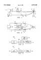
- FIG. 1is a schematic diagram in elevation of an embodiment of the invention
- FIG. 2is a top schematic diagram of the embodiment of the invention of FIG. 1;
- FIG. 3is an electrical schematic diagram of one embodiment of the transmitter circuit located in a transmitter unit.
- FIG. 4is an electrical schematic diagram of one embodiment of a receiver.
- FIGS. 1-4 of the drawingslike numerals being used for like and corresponding parts of the various drawings.
- FIGS. 1 and 2operator 10 is shown in boat 12.
- Boat 12has a main propulsion motor such as outboard motor 14 and a trolling motor 16. Any number of trolling motors may be adapted for use with the present invention.
- a main propulsion motorsuch as outboard motor 14
- a trolling motor 16Any number of trolling motors may be adapted for use with the present invention.
- U.S. Pat. No. 4,099,478 to Alexander and assigned to Brunswick Corp., Skokie, Ill.which is incorporated herein for all purposes.
- Operator 10may be positioned within boat 12 remote from trolling motor 16 and outboard motor 14. Operator 10 may control trolling motor 16 from the remote position by use of an optical hand-held transmitter 18 or a foot-operated optical transmitter 20.
- the optical transmitteris an infrared (IR) transmitter.
- Transmitters 18 and 20contain transmitter circuits, which will be described in more detail below, which produce optical signals representing the desired speed of trolling motor 16 and the desired direction of trolling motor 16 with respect to boat 12.
- Transmitters 18 and 20may have, for example, left and right buttons or pedals for adjusting the desired direction and a third button or throttle for designating the desired speed.
- the optical signal developed by transmitters 18 and 20are received by an optical receiver 22.
- Optical receiver 22is also coupled to steering motor 24 and provides an appropriate signal to steering motor 24 to cause it to turn trolling motor 16 to move boat 12 in a desired direction.
- Optical receiver 22is coupled to trolling motor throttle 26, which controls the speed of trolling motor 16.
- steering motor 24to trolling motor 16
- numerous techniques known in the artmay be used; for example, reference is made to U.S. Pat. No. 5,171,173 to Henderson, et al. and assigned to Zebco Corporation, Tulsa, Okla., which is incorporated herein for all purposes, and U.S. Pat. No. 5,112,256 to Clement and assigned to Zebco Corporation, Tulsa, Okla., which is also incorporated herein for all purposes.
- optical reflectors 30may be attached to portion 32 of boat 12 to help reflect a stronger optical signal to receiver 22.
- Optical reflectors 30may be removably attached, for example, on both sides of boat 12 as shown in FIG. 2.
- Optical reflectors 30may be mirrored surfaces or a plurality of mirrored surfaces to reflect the optical signal from various points on boat 12 to receiver 22.
- Reflectors 30may be permanently attached or mounted in a temporary fashion such as by brackets.
- FIG. 2shows an example of an optical signal 34 being transmitted by hand-held transmitter 18 reflecting off a side optical reflector 30, being received by optical receiver 22, and avoiding obstacle 31.
- the control system of the present inventionmay also be adapted in one embodiment to control main propulsion motor 14.
- a steering motor 36may be attached to main propulsion motor 14 to turn motor 14 with respect to boat 12 and thereby steer boat 12 in a desired direction.
- a throttlemay also be provided for controlling the speed of motor 14.
- An optical receiver 38may be coupled to steering motor 36 to provide an appropriate signal to turn motor 14 as desired in response to an optical signal representing the desired direction and coupled to the throttle for controlling the speed of motor 14 in response to the optical signal.
- one or more optical reflectors 40may be attached to an inner portion 32 of boat 12 intermediate of the anticipated position of operator 10 and motor 14, e.g., position 42. Reflectors 40 may be of the same type design as reflectors 30.
- Hand-held transmitter 18 or foot-operated transmitter 20may be used for generating optical signals indicative of the desired direction and speed of motor 14.
- FIG. 3shows a block diagram for optical transmitter circuit 100 that may be located within optical transmitters 18 and 20.
- Optical transmitter circuit 100includes input 102 coupled to processor 104.
- Input 102receives human entered commands from, for example, the buttons on a remote control to control trolling motor 16. Examples of the commands include left turn, right turn, more speed, less speed, or other appropriate inputs for controlling the functions of trolling motor 16.
- These commands from input 102are provided to processor 104.
- Processor 104receives these commands and generates the appropriate output commands for controlling trolling motor 16.
- the commands generated by processor 106are provided to transmitter/IR source 106. Coupled to processor 104 and transmitter/IR source 106 is power source 108.
- power source 108would be a battery suitable for placement in hand-held transmitter 18 or foot-operated transmitter 20.
- transmitter/IR source 106uses the power from power source 108, transmitter/IR source 106 transmits the commands from processor 104 as optical signals.
- Processor 104 and transmitter/IR source 106may be embodied in commercially available optical circuit part number PIC16C54/P/XT available from Microchip Technology Inc., of Chandler, Ariz.
- FIG. 4is a block diagram of one embodiment of optical receiver circuit 200 for use as receiver 22 or receiver 38.
- Receiver circuit 200includes optical receiver 202 for receiving the optical signals transmitted by transmitter/IR source 106 of transmitter circuit 100.
- Optical receiver 202provides the commands it receives to processor 204.
- Processor 204generates control signals that are provided to motor controls 206 which include steering motor 24 and throttle 26. Motor controls 206 then control trolling motor 16 (or outboard motor 14) as previously described.
- Optical receiver 202 and processor 204may be embodied in commercially available optical circuit part number PIC16C54/P/XT from Microchip Technology Inc., of Chandler, Ariz. It is noted that while examples of optical circuits 100 and 200 have been provided, that the present invention is not intended to be limited by any particular circuit or combination of circuit elements.
- infrared (IR) transmitter 18, 22, 100 and receiver 38, 200may be used, and an EPROM-based 8-bit CMOS microcontroller may be utilized.
- IRinfrared
- EPROM-based 8-bit CMOS microcontrollermay be utilized.
- General referenceis made to U.S. Pat. No. 5,473,758, assigned to Microchip Technology, Inc., which is incorporated for all purposes.
- the transmitter 18, 22, 100it may have a port B and a port A.
- Port B, bits 0-7could be devoted to input, and port A, bits 1-3, may set to input.
- Port A, bit 0may be set for output.
- a watchdog timermay be turned off initially.
- the microcontrollermay be maintained in a sleep mode.
- a data string indicting power onmay then be sent to the receiver 38, 200.
- a wake signalmay then be generated on a MCLR line when a switch is pressed. The signal may be an active logic low for about 10 micro-seconds.
- ports B, bits 0-7, and port A, bit 3may be read to determine which inputs are low indicating a switch closure.
- Port A, bit 0,may then generate a 40 kilohertz carrier which will activate the IR output device.
- Port A, bit 0,may then send a data string modulating the 40 kilohertz carrier.
- a data format that may be usedis as follows.
- Port A, bit 2may equal 100 milliseconds wide; Port A, bit 3, may equal 90 milliseconds wide; Port B, bit 7, may be 80 milliseconds wide; Port B, bit 6, may be 70 milliseconds wide; Port B, bit 5, may be 60 milliseconds wide; Port B, bit 4, may be 50 milliseconds wide; Port B, bit 3, may be 40 milliseconds; Port B, bit 2, may be 30 milliseconds wide; Port B, bit 1, may be 20 milliseconds wide; and Port B, bit 0, may be 10 milliseconds wide.
- the carrier and data stringmay be generated on port A, bit 0. Thereafter, port A, bit 2 may be checked for a low battery condition. If port A, bit 2 is low, the data string for a low battery may be sent also. After a switch closure is detected and transmitted, port B may be monitored to detect the switch opening. The data string may be repeatedly transmitted until the switch is opened and the port returns at logic high.
- Port Abits 1-3 may be set to input; port A, bit 3 may be set to output; port B, bit 0-7 may be set to a logic one outputs; and watchdog timer may be off.
- the microcontrollermay continuously monitor port A, bit 0 for a data string to be sent. After the start bit is detected, it may wait for the end of the start bit indicated by a logic low. The next bit may indicate switch bit data. After timing the data bit, it may be stored until a stop bit is detected. The output will then be a logic low sent to the corresponding output port bit. This logic state may remain as long as the transmitter is sending the switch closure. When the transmitter stops sending the switch closure, port B may change to a logic one.
- the foot pedal "on” signalWhen a low battery data string is received, the foot pedal "on” signal may be toggled on and off every 500 milliseconds.
- the receiver 38, 200may continue to toggle the "on” signal until the next transmission from the IR transmitter 18, 22, 100. It is to be understood that this is but one of many possible approaches to programming related to aspects of the invention.
Landscapes
- Engineering & Computer Science (AREA)
- Chemical & Material Sciences (AREA)
- Combustion & Propulsion (AREA)
- Mechanical Engineering (AREA)
- Ocean & Marine Engineering (AREA)
- Radar, Positioning & Navigation (AREA)
- Remote Sensing (AREA)
- Physics & Mathematics (AREA)
- Aviation & Aerospace Engineering (AREA)
- General Physics & Mathematics (AREA)
- Automation & Control Theory (AREA)
- Electromagnetism (AREA)
- Computer Networks & Wireless Communication (AREA)
- Signal Processing (AREA)
- Toys (AREA)
Abstract
Description
Claims (12)
Priority Applications (3)
| Application Number | Priority Date | Filing Date | Title |
|---|---|---|---|
| US08/766,571US5797339A (en) | 1996-12-12 | 1996-12-12 | Optical remote control for trolling motors and method of control |
| CA002219565ACA2219565A1 (en) | 1996-12-12 | 1997-10-29 | Optical remote control for trolling motors and method of control |
| JP9340842AJPH10175598A (en) | 1996-12-12 | 1997-11-27 | Control system and control method for trawling motor |
Applications Claiming Priority (1)
| Application Number | Priority Date | Filing Date | Title |
|---|---|---|---|
| US08/766,571US5797339A (en) | 1996-12-12 | 1996-12-12 | Optical remote control for trolling motors and method of control |
Publications (1)
| Publication Number | Publication Date |
|---|---|
| US5797339Atrue US5797339A (en) | 1998-08-25 |
Family
ID=25076840
Family Applications (1)
| Application Number | Title | Priority Date | Filing Date |
|---|---|---|---|
| US08/766,571Expired - Fee RelatedUS5797339A (en) | 1996-12-12 | 1996-12-12 | Optical remote control for trolling motors and method of control |
Country Status (3)
| Country | Link |
|---|---|
| US (1) | US5797339A (en) |
| JP (1) | JPH10175598A (en) |
| CA (1) | CA2219565A1 (en) |
Cited By (7)
| Publication number | Priority date | Publication date | Assignee | Title |
|---|---|---|---|---|
| US20040058594A1 (en)* | 2002-09-19 | 2004-03-25 | Honda Giken Kogyo Kabushiki Kaisha | Outboard motor |
| US20130257316A1 (en)* | 2012-04-02 | 2013-10-03 | Brian D. Perry | Rotary encoders for use with trolling motors |
| US9266589B2 (en) | 2007-10-19 | 2016-02-23 | Ted V. Grace | Watercraft automation and aquatic effort data utilization |
| US20160121989A1 (en)* | 2014-10-31 | 2016-05-05 | Furuno Electric Co., Ltd. | Remote control device, and method and system for remotely steering ship |
| US11173996B2 (en)* | 2007-08-03 | 2021-11-16 | Johnson Outdoors Inc. | Bidirectional wireless controls for marine devices |
| US12024271B2 (en) | 2020-10-22 | 2024-07-02 | Yamaha Hatsudoki Kabushiki Kaisha | Vessel operation system and vessel |
| US12187396B2 (en) | 2020-10-22 | 2025-01-07 | Yamaha Hatsudoki Kabushiki Kaisha | Vessel operation system and vessel |
Families Citing this family (3)
| Publication number | Priority date | Publication date | Assignee | Title |
|---|---|---|---|---|
| JP3973090B2 (en)* | 2002-09-19 | 2007-09-05 | 本田技研工業株式会社 | Outboard motor |
| US7229331B2 (en)* | 2005-01-24 | 2007-06-12 | Enviroprop Corporation | Shroud for a hydro thrust device |
| US9335412B2 (en)* | 2013-03-14 | 2016-05-10 | Navico Holding As | Sonar transducer assembly |
Citations (28)
| Publication number | Priority date | Publication date | Assignee | Title |
|---|---|---|---|---|
| US2253757A (en)* | 1938-05-18 | 1941-08-26 | Bugatti Ettore | Propeller actuated machine |
| US2804838A (en)* | 1955-11-16 | 1957-09-03 | Harold W Moser | Trolling outboard motor control |
| US2877733A (en)* | 1957-01-22 | 1959-03-17 | Garrett H Harris | Electric steering and power control system for outboard motors |
| US2972328A (en)* | 1957-07-25 | 1961-02-21 | James E Hodgson | Tilting mechanism for outboard motors |
| US3026545A (en)* | 1958-07-31 | 1962-03-27 | Braincon Corp | Retrieving vessel and launcher therefor |
| US3387582A (en)* | 1966-05-06 | 1968-06-11 | William R. Reeves | Radio controlled fishing boat |
| US3598947A (en)* | 1969-11-03 | 1971-08-10 | Osborn Engineering Corp | Pedal operated control for electric fishing motors |
| US3602181A (en)* | 1969-06-20 | 1971-08-31 | Garrett H Harris | Outboard motor steering control |
| US3604389A (en)* | 1969-01-27 | 1971-09-14 | Cable Ferry Systems | Water transportation system with shore-based propulsion |
| US3606858A (en)* | 1970-01-19 | 1971-09-21 | Neal B Edwards | Remotely steerable electric outboard motor |
| US3689927A (en)* | 1971-07-08 | 1972-09-05 | Robert T Boston | Radio-controlled decoy |
| US3765362A (en)* | 1972-05-04 | 1973-10-16 | J Gitchel | Dynamic balance sail control |
| US3807345A (en)* | 1972-01-20 | 1974-04-30 | Magalectric Corp | Trolling motor steering and speed control means |
| US3889625A (en)* | 1973-10-01 | 1975-06-17 | William G Roller | Control cable connection for an electric trolling motor |
| US3952681A (en)* | 1974-04-01 | 1976-04-27 | Tucker Systems, Inc. | Automatic steering system for vessels with a wireless remote control and course change capability |
| US3980039A (en)* | 1975-10-29 | 1976-09-14 | Shakespeare Company | Electrically operated bow mount for trolling motor |
| US4008500A (en)* | 1975-09-02 | 1977-02-22 | Hall Jr Clarence Addison | Fishing boat platform |
| US4114074A (en)* | 1976-11-23 | 1978-09-12 | Shakespeare Of Arkansas, Inc. | Device for electronic direction control of trolling motors |
| US4143436A (en)* | 1977-03-04 | 1979-03-13 | Jones Roy E | Directional control mechanism for a trolling motor |
| US4152703A (en)* | 1976-09-01 | 1979-05-01 | Dan-Mar Co. | Homing device |
| US4161077A (en)* | 1978-05-08 | 1979-07-17 | Charles J. Ciaccio | Radio controlled fishing apparatus |
| US4224762A (en)* | 1978-05-02 | 1980-09-30 | Mccaslin Robert E | Radio controlled toy vehicle |
| US4565529A (en)* | 1983-08-17 | 1986-01-21 | Aertker Walter P | Remotely controlled steering apparatus for outboard trolling motors |
| US4614900A (en)* | 1985-05-03 | 1986-09-30 | Young Joseph C | Remote controlled driving system for a boat |
| US5050519A (en)* | 1989-04-24 | 1991-09-24 | Architectural Control Systems, Inc. | Boat trolling motor control |
| US5073979A (en)* | 1990-05-29 | 1991-12-17 | Webb Edward L | Reflector for infrared remote control transmitter |
| JPH05175910A (en)* | 1991-12-24 | 1993-07-13 | Sony Corp | Omnidirectional light receiving device |
| US5606930A (en)* | 1995-03-10 | 1997-03-04 | Leblanc; Garry R. | Hand operated trolling motor control station |
- 1996
- 1996-12-12USUS08/766,571patent/US5797339A/ennot_activeExpired - Fee Related
- 1997
- 1997-10-29CACA002219565Apatent/CA2219565A1/ennot_activeAbandoned
- 1997-11-27JPJP9340842Apatent/JPH10175598A/enactivePending
Patent Citations (30)
| Publication number | Priority date | Publication date | Assignee | Title |
|---|---|---|---|---|
| US2253757A (en)* | 1938-05-18 | 1941-08-26 | Bugatti Ettore | Propeller actuated machine |
| US2804838A (en)* | 1955-11-16 | 1957-09-03 | Harold W Moser | Trolling outboard motor control |
| US2877733A (en)* | 1957-01-22 | 1959-03-17 | Garrett H Harris | Electric steering and power control system for outboard motors |
| US2972328A (en)* | 1957-07-25 | 1961-02-21 | James E Hodgson | Tilting mechanism for outboard motors |
| US3026545A (en)* | 1958-07-31 | 1962-03-27 | Braincon Corp | Retrieving vessel and launcher therefor |
| US3387582A (en)* | 1966-05-06 | 1968-06-11 | William R. Reeves | Radio controlled fishing boat |
| US3604389A (en)* | 1969-01-27 | 1971-09-14 | Cable Ferry Systems | Water transportation system with shore-based propulsion |
| US3602181A (en)* | 1969-06-20 | 1971-08-31 | Garrett H Harris | Outboard motor steering control |
| US3598947A (en)* | 1969-11-03 | 1971-08-10 | Osborn Engineering Corp | Pedal operated control for electric fishing motors |
| US3606858A (en)* | 1970-01-19 | 1971-09-21 | Neal B Edwards | Remotely steerable electric outboard motor |
| US3689927A (en)* | 1971-07-08 | 1972-09-05 | Robert T Boston | Radio-controlled decoy |
| US3807345A (en)* | 1972-01-20 | 1974-04-30 | Magalectric Corp | Trolling motor steering and speed control means |
| US3765362A (en)* | 1972-05-04 | 1973-10-16 | J Gitchel | Dynamic balance sail control |
| US3889625A (en)* | 1973-10-01 | 1975-06-17 | William G Roller | Control cable connection for an electric trolling motor |
| US3952681A (en)* | 1974-04-01 | 1976-04-27 | Tucker Systems, Inc. | Automatic steering system for vessels with a wireless remote control and course change capability |
| US4008500A (en)* | 1975-09-02 | 1977-02-22 | Hall Jr Clarence Addison | Fishing boat platform |
| US3980039A (en)* | 1975-10-29 | 1976-09-14 | Shakespeare Company | Electrically operated bow mount for trolling motor |
| US4152703A (en)* | 1976-09-01 | 1979-05-01 | Dan-Mar Co. | Homing device |
| US4114074A (en)* | 1976-11-23 | 1978-09-12 | Shakespeare Of Arkansas, Inc. | Device for electronic direction control of trolling motors |
| US4143436A (en)* | 1977-03-04 | 1979-03-13 | Jones Roy E | Directional control mechanism for a trolling motor |
| US4224762A (en)* | 1978-05-02 | 1980-09-30 | Mccaslin Robert E | Radio controlled toy vehicle |
| US4161077A (en)* | 1978-05-08 | 1979-07-17 | Charles J. Ciaccio | Radio controlled fishing apparatus |
| US4565529A (en)* | 1983-08-17 | 1986-01-21 | Aertker Walter P | Remotely controlled steering apparatus for outboard trolling motors |
| US4824408A (en)* | 1983-08-17 | 1989-04-25 | N. Elton Dry | Remotely controlled steering apparatus for outboard trolling motors |
| US4824408B1 (en)* | 1983-08-17 | 1995-07-25 | Dry N Elton | Remotely controlled steering apparatus outboard trolling motors |
| US4614900A (en)* | 1985-05-03 | 1986-09-30 | Young Joseph C | Remote controlled driving system for a boat |
| US5050519A (en)* | 1989-04-24 | 1991-09-24 | Architectural Control Systems, Inc. | Boat trolling motor control |
| US5073979A (en)* | 1990-05-29 | 1991-12-17 | Webb Edward L | Reflector for infrared remote control transmitter |
| JPH05175910A (en)* | 1991-12-24 | 1993-07-13 | Sony Corp | Omnidirectional light receiving device |
| US5606930A (en)* | 1995-03-10 | 1997-03-04 | Leblanc; Garry R. | Hand operated trolling motor control station |
Non-Patent Citations (2)
| Title |
|---|
| Sears SpeciaLog, Boating and Fishing, 1986/87, p. 18.* |
| Zebco Company, MotorGuide 1995, 21 pages.* |
Cited By (20)
| Publication number | Priority date | Publication date | Assignee | Title |
|---|---|---|---|---|
| US20040058594A1 (en)* | 2002-09-19 | 2004-03-25 | Honda Giken Kogyo Kabushiki Kaisha | Outboard motor |
| US6962513B2 (en)* | 2002-09-19 | 2005-11-08 | Honda Giken Kogyo Kabushiki Kaisha | Outboard motor |
| US11173996B2 (en)* | 2007-08-03 | 2021-11-16 | Johnson Outdoors Inc. | Bidirectional wireless controls for marine devices |
| US10322780B2 (en) | 2007-10-19 | 2019-06-18 | Garmin Switzerland Gmbh | Watercraft automation and aquatic effort data utilization |
| US9708042B2 (en) | 2007-10-19 | 2017-07-18 | Garmin Switzerland Gmbh | Watercraft automation and aquatic effort data utilization |
| US10507895B2 (en) | 2007-10-19 | 2019-12-17 | Garmin Switzerland Gmbh | Watercraft automation and aquatic effort data utilization |
| US9394040B2 (en) | 2007-10-19 | 2016-07-19 | Ted V. Grace | Watercraft automation and aquatic effort data utilization |
| US9446831B2 (en) | 2007-10-19 | 2016-09-20 | Garmin Switzerland Gmbh | Watercraft automation and aquatic effort data utilization |
| US9463860B2 (en) | 2007-10-19 | 2016-10-11 | Garmin Switzerland Gmbh | Watercraft automation and aquatic effort data utilization |
| US9505477B2 (en) | 2007-10-19 | 2016-11-29 | Garmin Switzerland Gmbh | Watercraft automation and aquatic effort data utilization |
| US9522721B2 (en) | 2007-10-19 | 2016-12-20 | Garmin Switzerland Gmbh | Watercraft automation and aquatic effort data utilization |
| US9944365B2 (en) | 2007-10-19 | 2018-04-17 | Garmin Switzerland Gmbh | Watercraft automation and aquatic effort data utilization |
| US9266589B2 (en) | 2007-10-19 | 2016-02-23 | Ted V. Grace | Watercraft automation and aquatic effort data utilization |
| US9758222B2 (en) | 2007-10-19 | 2017-09-12 | Garmin Switzerland Gmbh | Watercraft automation and aquatic effort data utilization |
| US9160210B2 (en)* | 2012-04-02 | 2015-10-13 | Brunswick Corporation | Rotary encoders for use with trolling motors |
| US20130257316A1 (en)* | 2012-04-02 | 2013-10-03 | Brian D. Perry | Rotary encoders for use with trolling motors |
| US9682761B2 (en)* | 2014-10-31 | 2017-06-20 | Furuno Electric Company Limited | Remote control device, and method and system for remotely steering ship |
| US20160121989A1 (en)* | 2014-10-31 | 2016-05-05 | Furuno Electric Co., Ltd. | Remote control device, and method and system for remotely steering ship |
| US12024271B2 (en) | 2020-10-22 | 2024-07-02 | Yamaha Hatsudoki Kabushiki Kaisha | Vessel operation system and vessel |
| US12187396B2 (en) | 2020-10-22 | 2025-01-07 | Yamaha Hatsudoki Kabushiki Kaisha | Vessel operation system and vessel |
Also Published As
| Publication number | Publication date |
|---|---|
| JPH10175598A (en) | 1998-06-30 |
| CA2219565A1 (en) | 1998-06-12 |
Similar Documents
| Publication | Publication Date | Title |
|---|---|---|
| US5797339A (en) | Optical remote control for trolling motors and method of control | |
| CA2321308C (en) | A method and system for directing a following device toward a movable object | |
| US6054831A (en) | Radio frequency remote control for trolling motors | |
| US20010015165A1 (en) | Autopilot-based steering and maneuvering system for boats | |
| WO1998051892A1 (en) | Apparatus for remotely controlling device for mobile body | |
| JPS63186496U (en) | ||
| US6338664B1 (en) | Toy vehicle having center steering circuit and remote controller with toggle function | |
| US5050519A (en) | Boat trolling motor control | |
| JP4675023B2 (en) | Remote control traveling device | |
| JP3256182B2 (en) | Ship radio control system | |
| US5859517A (en) | Trolling motor controller | |
| CA2363179A1 (en) | Light guided autopilot | |
| US7120428B2 (en) | Remote locomotive control | |
| US6322405B1 (en) | Reversing control for trolling motor propulsion system | |
| JPS6139640A (en) | Optical fiber type non-contact underwater transmitting method | |
| US10093353B2 (en) | Power-assisted steering system and mobile inspection device | |
| JPH0219656U (en) | ||
| KR940002619B1 (en) | Apparatus for interface laser machine and cnc | |
| JPS639185Y2 (en) | ||
| KR0117651Y1 (en) | Driving control circuit for remocon's receiver | |
| JP2941391B2 (en) | Antenna drive | |
| JP2001137563A (en) | Transmitter for toy | |
| CA2014397C (en) | Boat trolling motor control | |
| US6201483B1 (en) | Boat steering centered indicator | |
| JP2634705B2 (en) | Remote control device for unmanned vehicles |
Legal Events
| Date | Code | Title | Description |
|---|---|---|---|
| AS | Assignment | Owner name:BRUNSWICK CORPORATION, A DE. CORP., ILLINOIS Free format text:ASSIGNMENT OF ASSIGNORS INTEREST;ASSIGNORS:MOORE, PRENTICE GEAN;MALAK, STEPHEN P.;REEL/FRAME:008356/0143;SIGNING DATES FROM 19961111 TO 19961119 | |
| FPAY | Fee payment | Year of fee payment:4 | |
| REFU | Refund | Free format text:REFUND - PAYMENT OF MAINTENANCE FEE, 8TH YEAR, LARGE ENTITY (ORIGINAL EVENT CODE: R1552); ENTITY STATUS OF PATENT OWNER: LARGE ENTITY | |
| FPAY | Fee payment | Year of fee payment:8 | |
| FEPP | Fee payment procedure | Free format text:PAYOR NUMBER ASSIGNED (ORIGINAL EVENT CODE: ASPN); ENTITY STATUS OF PATENT OWNER: LARGE ENTITY | |
| AS | Assignment | Owner name:JPMORGAN CHASE BANK, N.A., TEXAS Free format text:SECURITY AGREEMENT;ASSIGNORS:BRUNSWICK CORPORATION;TRITON BOAT COMPANY, L.P.;ATTWOOD CORPORATION;AND OTHERS;REEL/FRAME:022092/0365 Effective date:20081219 Owner name:JPMORGAN CHASE BANK, N.A.,TEXAS Free format text:SECURITY AGREEMENT;ASSIGNORS:BRUNSWICK CORPORATION;TRITON BOAT COMPANY, L.P.;ATTWOOD CORPORATION;AND OTHERS;REEL/FRAME:022092/0365 Effective date:20081219 | |
| AS | Assignment | Owner name:THE BANK OF NEW YORK MELLON TRUST COMPANY, N.A., I Free format text:SECURITY AGREEMENT;ASSIGNORS:BRUNSWICK CORPORATION;ATTWOOD CORPORATION;BOSTON WHALER, INC.;AND OTHERS;REEL/FRAME:023180/0493 Effective date:20090814 Owner name:THE BANK OF NEW YORK MELLON TRUST COMPANY, N.A.,IL Free format text:SECURITY AGREEMENT;ASSIGNORS:BRUNSWICK CORPORATION;ATTWOOD CORPORATION;BOSTON WHALER, INC.;AND OTHERS;REEL/FRAME:023180/0493 Effective date:20090814 | |
| REMI | Maintenance fee reminder mailed | ||
| LAPS | Lapse for failure to pay maintenance fees | ||
| STCH | Information on status: patent discontinuation | Free format text:PATENT EXPIRED DUE TO NONPAYMENT OF MAINTENANCE FEES UNDER 37 CFR 1.362 | |
| FP | Lapsed due to failure to pay maintenance fee | Effective date:20100825 | |
| AS | Assignment | Owner name:BRUNSWICK BOWLING & BILLIARDS CORPORATION, ILLINOI Free format text:RELEASE BY SECURED PARTY;ASSIGNOR:JPMORGAN CHASE BANK, N.A., AS ADMINISTRATIVE AGENT;REEL/FRAME:026026/0001 Effective date:20110321 Owner name:LUND BOAT COMPANY, MINNESOTA Free format text:RELEASE BY SECURED PARTY;ASSIGNOR:JPMORGAN CHASE BANK, N.A., AS ADMINISTRATIVE AGENT;REEL/FRAME:026026/0001 Effective date:20110321 Owner name:LAND 'N' SEA DISTRIBUTING, INC., FLORIDA Free format text:RELEASE BY SECURED PARTY;ASSIGNOR:JPMORGAN CHASE BANK, N.A., AS ADMINISTRATIVE AGENT;REEL/FRAME:026026/0001 Effective date:20110321 Owner name:ATTWOOD CORPORATION, MICHIGAN Free format text:RELEASE BY SECURED PARTY;ASSIGNOR:JPMORGAN CHASE BANK, N.A., AS ADMINISTRATIVE AGENT;REEL/FRAME:026026/0001 Effective date:20110321 Owner name:TRITON BOAT COMPANY, L.P., TENNESSEE Free format text:RELEASE BY SECURED PARTY;ASSIGNOR:JPMORGAN CHASE BANK, N.A., AS ADMINISTRATIVE AGENT;REEL/FRAME:026026/0001 Effective date:20110321 Owner name:BRUNSWICK COMMERICAL & GOVERNMENT PRODUCTS, INC., Free format text:RELEASE BY SECURED PARTY;ASSIGNOR:JPMORGAN CHASE BANK, N.A., AS ADMINISTRATIVE AGENT;REEL/FRAME:026026/0001 Effective date:20110321 Owner name:BRUNSWICK CORPORATION, ILLINOIS Free format text:RELEASE BY SECURED PARTY;ASSIGNOR:JPMORGAN CHASE BANK, N.A., AS ADMINISTRATIVE AGENT;REEL/FRAME:026026/0001 Effective date:20110321 Owner name:BRUNSWICK LEISURE BOAT COMPANY, LLC, INDIANA Free format text:RELEASE BY SECURED PARTY;ASSIGNOR:JPMORGAN CHASE BANK, N.A., AS ADMINISTRATIVE AGENT;REEL/FRAME:026026/0001 Effective date:20110321 Owner name:BRUNSWICK FAMILY BOAT CO. INC., WASHINGTON Free format text:RELEASE BY SECURED PARTY;ASSIGNOR:JPMORGAN CHASE BANK, N.A., AS ADMINISTRATIVE AGENT;REEL/FRAME:026026/0001 Effective date:20110321 Owner name:BOSTON WHALER, INC., FLORIDA Free format text:RELEASE BY SECURED PARTY;ASSIGNOR:JPMORGAN CHASE BANK, N.A., AS ADMINISTRATIVE AGENT;REEL/FRAME:026026/0001 Effective date:20110321 | |
| AS | Assignment | Owner name:JPMORGAN CHASE BANK, N.A., AS ADMINISTRATIVE AGENT Free format text:SECURITY AGREEMENT;ASSIGNORS:BRUNSWICK CORPORATION;ATTWOOD CORPORATION;BOSTON WHALER, INC.;AND OTHERS;REEL/FRAME:026072/0239 Effective date:20110321 | |
| AS | Assignment | Owner name:BRUNSWICK CORPORATION, ILLINOIS Free format text:RELEASE BY SECURED PARTY;ASSIGNOR:THE BANK OF NEW YORK MELLON;REEL/FRAME:031973/0242 Effective date:20130717 | |
| AS | Assignment | Owner name:LAND 'N' SEA DISTRIBUTING, INC., ILLINOIS Free format text:RELEASE BY SECURED PARTY;ASSIGNOR:JPMORGAN CHASE BANK, N.A.;REEL/FRAME:034794/0300 Effective date:20141226 Owner name:BRUNSWICK CORPORATION, ILLINOIS Free format text:RELEASE BY SECURED PARTY;ASSIGNOR:JPMORGAN CHASE BANK, N.A.;REEL/FRAME:034794/0300 Effective date:20141226 Owner name:ATTWOOD CORPORATION, ILLINOIS Free format text:RELEASE BY SECURED PARTY;ASSIGNOR:JPMORGAN CHASE BANK, N.A.;REEL/FRAME:034794/0300 Effective date:20141226 Owner name:BRUNSWICK COMMERCIAL & GOVERNMENT PRODUCTS, INC., Free format text:RELEASE BY SECURED PARTY;ASSIGNOR:JPMORGAN CHASE BANK, N.A.;REEL/FRAME:034794/0300 Effective date:20141226 Owner name:BRUNSWICK FAMILY BOAT CO. INC., ILLINOIS Free format text:RELEASE BY SECURED PARTY;ASSIGNOR:JPMORGAN CHASE BANK, N.A.;REEL/FRAME:034794/0300 Effective date:20141226 Owner name:BRUNSWICK BOWLING & BILLIARDS CORPORATION, ILLINOI Free format text:RELEASE BY SECURED PARTY;ASSIGNOR:JPMORGAN CHASE BANK, N.A.;REEL/FRAME:034794/0300 Effective date:20141226 Owner name:LUND BOAT COMPANY, ILLINOIS Free format text:RELEASE BY SECURED PARTY;ASSIGNOR:JPMORGAN CHASE BANK, N.A.;REEL/FRAME:034794/0300 Effective date:20141226 Owner name:BOSTON WHALER, INC., ILLINOIS Free format text:RELEASE BY SECURED PARTY;ASSIGNOR:JPMORGAN CHASE BANK, N.A.;REEL/FRAME:034794/0300 Effective date:20141226 Owner name:BRUNSWICK LEISURE BOAT COMPANY, LLC, ILLINOIS Free format text:RELEASE BY SECURED PARTY;ASSIGNOR:JPMORGAN CHASE BANK, N.A.;REEL/FRAME:034794/0300 Effective date:20141226 |