US5795470A - Magnetic separation apparatus - Google Patents
Magnetic separation apparatusDownload PDFInfo
- Publication number
- US5795470A US5795470AUS08/482,636US48263695AUS5795470AUS 5795470 AUS5795470 AUS 5795470AUS 48263695 AUS48263695 AUS 48263695AUS 5795470 AUS5795470 AUS 5795470A
- Authority
- US
- United States
- Prior art keywords
- magnetic
- particles
- magnets
- plenum
- container
- Prior art date
- Legal status (The legal status is an assumption and is not a legal conclusion. Google has not performed a legal analysis and makes no representation as to the accuracy of the status listed.)
- Expired - Lifetime
Links
Images


Classifications
- A—HUMAN NECESSITIES
- A23—FOODS OR FOODSTUFFS; TREATMENT THEREOF, NOT COVERED BY OTHER CLASSES
- A23B—PRESERVATION OF FOODS, FOODSTUFFS OR NON-ALCOHOLIC BEVERAGES; CHEMICAL RIPENING OF FRUIT OR VEGETABLES
- A23B2/00—Preservation of foods or foodstuffs, in general
- A23B2/60—Preservation of foods or foodstuffs, in general by treatment with electric currents without heating effect
- B—PERFORMING OPERATIONS; TRANSPORTING
- B03—SEPARATION OF SOLID MATERIALS USING LIQUIDS OR USING PNEUMATIC TABLES OR JIGS; MAGNETIC OR ELECTROSTATIC SEPARATION OF SOLID MATERIALS FROM SOLID MATERIALS OR FLUIDS; SEPARATION BY HIGH-VOLTAGE ELECTRIC FIELDS
- B03C—MAGNETIC OR ELECTROSTATIC SEPARATION OF SOLID MATERIALS FROM SOLID MATERIALS OR FLUIDS; SEPARATION BY HIGH-VOLTAGE ELECTRIC FIELDS
- B03C1/00—Magnetic separation
- B03C1/02—Magnetic separation acting directly on the substance being separated
- B03C1/035—Open gradient magnetic separators, i.e. separators in which the gap is unobstructed, characterised by the configuration of the gap
- G—PHYSICS
- G01—MEASURING; TESTING
- G01N—INVESTIGATING OR ANALYSING MATERIALS BY DETERMINING THEIR CHEMICAL OR PHYSICAL PROPERTIES
- G01N35/00—Automatic analysis not limited to methods or materials provided for in any single one of groups G01N1/00 - G01N33/00; Handling materials therefor
- G01N35/0098—Automatic analysis not limited to methods or materials provided for in any single one of groups G01N1/00 - G01N33/00; Handling materials therefor involving analyte bound to insoluble magnetic carrier, e.g. using magnetic separation
Definitions
- the present inventionrelates to improvements in magnetic separators and methods of separation of magnetic particles and/or magnetic-associated entities from non-magnetic associated entities and media, having particular utility in various diagnostic, therapeutic and industrial procedures involving specific reactions.
- biospecific affinity reactionsare commonly employed in diagnostic testing of biological samples, or for the separation of a wide range of target substances, especially biological entities such as cells, proteins, nucleic acid sequences, and the like.
- Small magnetic particlessuch as those mentioned above, generally fall into two broad categories.
- the first categoryincludes particles that are permanently magnetizable, or ferromagnetic; and the second comprises particles that demonstrate bulk magnetic behavior only when subjected to a magnetic field.
- the latterare referred to as magnetically responsive particles.
- Materials displaying magnetically responsive behaviorare sometimes described as superparamagnetic.
- materials exhibiting bulk ferromagnetic propertiese.g., magnetic iron oxide, may be characterized as superparamagnetic when provided in crystals of about 30 nm or less in diameter. Larger crystals of ferromagnetic materials, by contrast, retain permanent magnet characteristics after exposure to a magnetic field and tend to aggregate thereafter due to strong particle-particle interaction.
- the above-described magnetic separatorshave the disadvantage that the magnetic particles attracted toward the magnets tend to form in multiple layers on the inner surface of the sample container where they are entrapped along with impurities that are difficult to remove even with vigorous washing.
- One magnetic separator of the inventioncomprises a magnetic means capable of generating a high gradient magnetic field in a gap or receptacle into which at least one vessel containing a test medium may be placed.
- the containerpreferably has a peripheral wall with an internal surface area and is adapted to receive the test medium with the magnetically responsive colloidal particles therein (hereinafter "the test medium being separated”).
- the magnetic field gradient generating meansis disposed outside the container and provides an "open" field gradient inside the container, wherein the magnetic field is stronger in the test medium along the internal wall surface of the container than it is in the test medium most distant from the wall.
- suitable containersinclude microtiter wells, test tubes, capillary tubes closed at one end, or other non-magnetic cylindrical walled vessels defining a chamber for performing the desired separation.
- a plurality of test samplesmay be processed simultaneously through the use of a carrier capable of holding more than one sample container.
- the carrierincludes means for holding a plurality of containers around the periphery of the carrier.
- a suitable containeris a conduit or tube having openings at each end.
- Such containersare preferably non-magnetic, e.g., glass or plastic, and of cylindrical configuration.
- the containerhas an inlet opening at one end for receiving the test medium which is exposed to the high magnetic field gradient at the center portion of the container.
- the containermay also have one or more non-magnetic baffles spaced apart within the container between the two ends. The baffles are dimensioned to restrict the cross-sectional area of the passageway in which the test medium flows through the container to a region surrounding the axis.
- the bafflesare preferably inclined radially downwardly along the direction of flow, to guide toward the wall any magnetically responsive colloidal particles coming into contact therewith.
- the conduitpreferably has laterally spaced apart outlet means disposed at the end opposite the inlet.
- One outlet meansmay be provided along the periphery of the outlet end of the container for collecting the magnetic particles.
- Another outlet meansis centrally positioned at the outlet end for discharging the test medium.
- magnetic particles in the test medium adjacent the wall of the container near the edge of the receptacleare subject to considerably greater magnetic force than particles in the test medium furthest from the wall of the container, toward the center of the gap or receptacle where the field strength falls away to zero.
- the magnetic meansmay advantageously comprise magnetic flux concentrating means, particularly, if the gap or receptacle defined by the magnets is much larger than the cross-section of the container or carrier. Suitable for this purpose are pole pieces of various geometries, which are magnetized or magnetizable via an induced field.
- the magnets comprising the magnetic meansmay be attached magnetically to, or otherwise joined to the yoke, e.g. by cementing with epoxy, to hold the magnets in a fixed position relative to one another.
- the particlesare initially dispersed in the non-magnetic test medium, forming a stable suspension therein.
- the magnetic particlestypically comprise a receptor capable of specific binding to a target substance of interest in the test medium. If it is desired to separate target substances from test medium in a steady state, a suitable container holding the test medium and the receptor-magnetic particle conjugates are placed in the magnetic separator for batch-wise processing.
- the external magnetic means disposed around the containerproduces a magnetic field gradient in the test medium, which causes the magnetic particles to move toward the wall and to become adhered thereto.
- a method for separating one or more target substances from a test fluidwhich comprises mixing the test fluid with a quantity of magnetic particles to produce a suspension, which includes a magnetic component and a non-magnetic component, the target substance or substances being associated with the magnetic component.
- a magnetically inert fluid phaseis established in a container having a collection surface therein, and the aforementioned suspension is introduced into the container as a distinct phase from the magnetically inert phase.
- the distinct phaseis stable within the container, so that the magnetic and non-magnetic components of the suspension are confined within the distinct phase.
- a magnetic fieldis generated in the container, and possesses a sufficiently high intensity in a region adjacent the collection surface to cause disintegration of the distinct phase into its constituent magnetic and non-magnetic components.
- the distinct phaseis attracted toward the collection surface, and the magnetic component of the distinct phase is collected upon the collection surface when the distinct phase disintegrates in the region adjacent the collection surface.
- the non-magnetic component of the disintegrated phaseis removed from the region adjacent the collection surface.
- FIG. 1Ais a perspective view of a magnetic separation apparatus of the invention, portions of the apparatus being broken away for the purposes of illustration;
- FIG. 1Bis an elevational sectional diagram of the apparatus of FIG. 1A taken along the line 1B;
- FIG. 1Cis a plan view of the apparatus shown in FIG. 1A;
- FIG. 2is a graph of relative magnetic flux density along the line 1B versus distance
- FIG. 3is a plan view of a magnetic separation apparatus of the invention having a magnetic means comprising six magnets;
- FIG. 4is a fragmentary perspective view of a magnetic separation apparatus in which several containers are held in a carrier;
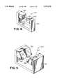
- FIG. 5is a view in perspective of a magnetic separation apparatus in which a flow-through test container is provided with internal baffles;
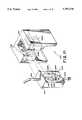
- FIGS. 7A and 7Bare schematic diagrams of multipolar magnetic separators having magnets of different cross-sectional area
- FIG. 8is a perspective view of a magnetic separation apparatus utilizing an opposing magnetic dipole
- FIG. 9is a perspective view of a magnetic separation apparatus utilizing a multiple opposing dipole
- FIG. 10is a perspective view of a magnetic separation apparatus utilizing a series of opposing dipoles
- FIG. 13is a perspective view of an apparatus for performing flow through separations in accordance with the invention.
- the arrangement of magnets 27 around the receptacle 33generates a magnetic field within the receptacle 33 that is substantially uniform along the peripheral wall of the container 23.
- the magnetic field within the receptacle 33is characterized by contours of equal magnetic flux density that are substantially circular within the receptacle 33, and thus the flux density contours are substantially aligned with the periphery of the container 23. Consequently, the angular component of the magnetic field gradient (i.e. along the peripheral wall 25 of the container 23) is substantially zero, and the magnetic flux density gradient is substantially orthogonal to the peripheral wall 25 of the container 23.
- the strength of the magnets and the distance therebetweenare selected to produce a high gradient magnetic field sufficient for separating colloidal superparamagnetic particles from a test medium.
- the container 23 used to hold the test mediummay comprise a microtiter well.
- the container 23is positioned substantially coaxially with a gap or receptacle 33 defined by the magnet faces. In that position, the magnetic field strength in the test medium 35 adjacent to the wall approaches the magnetic field strength generated by the magnets. In contrast, there is virtually no magnetic field in the part of the container located along the central axis 37 of receptacle 33, i.e., the test medium most distant from the wall.
- the wall of the microtiter well exposed to the test mediumprovides an ample surface area for adherence of the colloidal magnetic particles.
- An advantage of the magnetic separator of the inventionwhen utilized under the conditions described above, is that by appropriately regulating the quantity of magnetic colloid, the particles tend to deposit substantially uniformly upon surfaces in contact with the medium where the magnetic gradient is high. As a result, particles may be caused to be deposited on a broad portion of the internal surface area of the wall in what is effectively a single layer, as opposed to multiple layers or particle agglomerates, which tend to entrap potentially interfering substances, as when formed on a smaller surface, such as occurs in magnetic separators of the prior art.
- the colloidal magnetic particlesare sufficiently thinly deposited on the container surface that there is virtually no entrapment of potentially interfering substances.
- the portion of the container wall surface in contact with the test mediumbe selected so that the wall's aggregate collecting surface area is greater, by a factor of about 2, than the surface area that would be occupied by all of the magnetic particles in the test medium, if deposited in a substantially continuous single layer.
- the quantity of the magnetic colloid in the separation containermust be controlled relative to the size of the target entities and the surface area of the vessel which is available for collection of the biospecifically-bound magnetic particles when the container is placed within the apparatus.
- Monolayered collectiontends to enhance biospecificity of collection relative to multilayered collection in which non-target entities or substances may become entrapped within voids or interstices between layers of collected target entities.
- FIG. 3illustrates another embodiment of the magnetic separator of the invention that is similar to the magnetic separator shown in FIGS. 1A-C.
- the separator 121 shown in FIG. 3comprises a container 123 in the form of a cylindrical tube or the like.
- the containermay be closed at one end, e.g., a test tube for batch-wise processing, or open at both ends, e.g., a capillary or larger diameter tube for continuous processing.
- the containerhas a wall 125 and an opening for receiving the test medium being separated.
- the separatoralso comprises magnetic means represented by six magnets 127 which are equally spaced around the container. Suitable means may be provided for supporting the container 123 within the central portion of the separator.
- the carrier 241comprises a non-magnetic base 243, with separate non-magnetic compartments 253 fitted into the base. Each such compartment is dimensioned to support securely one of the containers 223 in an upright position such as by standing upon the base 243 or having the flared tops of the containers 223 rest upon the upper rim of the compartments.
- the container illustrated in FIGS. 5 and 6has a peripheral wall 325 that defines an inner cross-sectional space 362 inside the container.
- One end of the containerhas an inlet port 363 that is dimensioned to permit test medium to flow into the central portion 365 of the inner cross-sectional space between the wall and the central portion.
- the bafflesare also inclined downwardly along the direction of flow toward wall 325. Hence, in passing through the container, the magnetically responsive colloidal particles are attracted by the magnets 327 onto the baffles and toward the wall.
- the bafflesguide the particles along to a point at which the field gradient becomes sufficiently strong to cause the particles to adhere to the wall.
- the containeralso has at least two outlets. One outlet 369 is along the periphery of the wall for collection of the particles. A second outlet 371 is aligned with the axis of the container for discharge of the residual non-magnetic test medium.
- the containermay be removed from the magnetic field and manipulated to allow the magnetic particles to be dislodged from the walls and resuspended in a suitable liquid medium, e.g., to facilitate analysis.
- a suitable liquid mediume.g., to facilitate analysis.
- the magnetic separation apparatus and methods of the inventionpermit advantageous use of diffusion controlled solution kinetics of the primary incubation mixture.
- various analytical proceduresincluding quantitative determinations, may be performed on the magnetically immobilized colloid. Such steps include washes for removal of non-specifically bound substances, secondary immunochemical reactions or detection reactions (e.g., enzymatic, fluorescent or chemiluminescent reactions).
- the ability to retain the magnetic particles adhered to the wall of the container after the test medium has been removedis of considerable utility. Certain operations are more efficiently carried out in this way, such as washing or rinsing the target substance, e.g., cells or labeled components of a reaction mixture, while avoiding a separate resuspension step.
- secondary reactionssuch as those involving the interaction of labeled immunoreactive agents with a target substance carried by the magnetic particles may be performed more efficiently with the particles adhered to the wall.
- resuspension of the colloidal magnetic particlesis avoidable.
- substrate incubationis preferably carried out directly on the colloidal magnetic particles immobilized in the separation apparatus.
- An enzyme-labeled immunoassaymay be performed to determine the presence or quantity of a ligand, such as a cell-surface antigen, suspended within a test medium contained in a non-magnetic container.
- a quantity of colloidal magnetic particles having a biospecific receptor, such as a particular antibody for binding with the antigen,is added to the test medium along with a quantity of enzyme-linked receptor that is also specific to the ligand.
- the test mediumis then incubated under conditions causing binding of the antigen to both the enzyme-linked antibodies and the magnetic particles.
- the containeris then placed into a magnetic separator so that the magnetic particles are attracted toward and adhered to the interior wall of the container.
- the test mediummay then be removed from the container while leaving behind the magnetic particles which remain adhered to the wall.
- the remaining material adhered to the wallmay then be washed in order to remove any unbound substances. Such washing away of unbound material may be facilitated by initially controlling the concentration of magnetic particles so that material is deposited on the interior wall of the container in a substantially single layer thus avoiding entrapment of unwanted material in voids or pockets that would otherwise be formed between layers of magnetic particles.
- the presence or quantity of the cell-surface antigen or other ligand of interest present in the original test mediummay be measured by determining the activity of the enzyme which is bound via the biospecific antibody to the antigen which in turn is likewise bound to the magnetic particles.
- the enzyme activity determinationis preferably carried out while the magnetic particles remain adhered to the container wall, but may be performed after resuspension if desired.
- the determinationmay include standard enzyme activity measurements such as reaction with a chromogenic substance which may then be compared to a color standard or by conducting secondary immunochemical reactions or detection reactions involving the ligand.
- Performing the magnetic separation method of the invention batchwise, i.e. in a steady-state system, as described above, instead of in a flow through system,has certain advantages. Immobilized magnetic particles bearing the target substances are not dislodged due to collisions with other particles. Moreover, batchwise operation eliminates dislodgment of immobilized magnetic particles due to shear forces produced by a flowing test medium. In other words, the adherence of the magnetic particles to the wall is sufficiently strong to permit washing, secondary reactions, and interactions with other reagents to occur without appreciable dislodgment of the magnetic particles from the wall. In addition, the adherence of the magnetic particles to the container wall is maintained to some extent even if the container is removed from the magnetic field before further reaction with, or treatment of the particles.
- the separator of the inventionavoids the problem of dislodged particles noted above that commonly occurs when employing a flow through process.
- Multipole magnetic separation devicessuch as those described above in which near neighbor pole faces are of opposite polarity create high gradient fields wherein the magnitude of the gradient is limited only by the field density at the pole face and the distance separating opposing poles.
- the multipole devices of the inventionhave substantial advantage because the field strengths at the center of the opposing poles is zero (see FIG. 2). Hence, the gradients produced are only limited by the ability to produce fields greater than zero.
- FIG. 7Athere is shown a schematic arrangement of a multipole separator 421 in which one pair of magnets 426 are disposed longitudinally in a horizontal plane and a second pair of magnets 427 are disposed laterally, each pair of magnets being on opposite sides of a common gap or receptacle 423, which in the present instance accommodates two containers 453. Suitable means are provided for removably supporting the containers 453 within the receptacle 423.
- the magnets 426 and 427are mounted within a rectangular yoke 431.
- the laterally disposed magnets 427have a smaller cross-sectional area than the longitudinally disposed magnets 426.
- the containers 453are supported within the receptacle such that each of the containers is adjacent to one of the magnetic poles of smaller cross-sectional area.
- the larger magnets 426are oriented such that like poles, shown in FIG. 7A as north poles, are in confrontation across the gap or receptacle 423.
- the smaller magnets 427are also oriented with like poles, shown in FIG. 7A as south poles, are in confrontation across the gap or receptacle 423.
- the polarity of magnets 426 and 427may be reversed without departing from the scope of the invention as long as the relative arrangement of like and unlike poles is preserved.
- Lines of magnetic flux within such an arrangementare more greatly concentrated at the faces of the smaller magnets than would be the case in a multipole separator having identically-sized magnets of equal strength. Hence collection of magnetically-responsive particles occurs predominately upon the interior surfaces 425 of the containers 453 that are adjacent to the smaller pole faces 429 of the magnets 427.
- magnets of differing cross-sectional areamay also be extended to other separation geometries, such as the hexapole separator 521 shown in FIG. 7B.
- three magnets 526 and three magnets 527are mounted upon a circular yoke 531 at alternating positions and with alternating polarities about a hexagonal gap or receptacle 523.
- the magnets 526all have like poles facing the hexagonal gap, while the magnets 527 all have like poles facing the gap of a polarity opposite to the poles of the magnets 526 facing the gap.
- the cross-sectional area of the magnets 527is smaller than that of the magnets 526 in order to provide a higher flux density in the gap 523 adjacent to the pole faces of magnets 527 than the flux density in the gap 523 adjacent to the pole faces of magnets 526.
- Such a disparity in flux densityprovides for preferential collection upon the interior surfaces 525 of the three containers 553 within the gap 523 that are located adjacent to the pole faces of the smaller magnets 527.
- the containers 553may stand freely within the receptacle 523 or may be supported therein by an appropriately configured carrier as described in connection with FIG. 4.
- an opposing dipole separator 621includes two magnets 627 having like pole faces 629 in confrontation across a gap or receptacle which allows lateral as well as vertical insertion of a separation vessel (not shown) which is supported between the two magnets 627.
- the separator shown in FIG. 8also allows insertion and removal of the vessel at a range of angles having directional components defined by the lateral and vertical axes.
- Such an opposing dipole arrangementmay be constructed by, for example, mounting permanent magnets upon a yoke 631.
- a magnetic arrangement shown in FIG. 9such as a double dipole separator 721 provides greater localization and intensification of the magnetic gradient.
- a pair of opposing dipoles 727 and 726 of complementary polarityare mounted upon a yoke 731 such that junctions 728 are located between neighboring pole faces on each side of the gap or receptacle.
- Such an arrangementprovides confinement of the magnetic field to the regions within the receptacle about the junctions 728 to a greater extent than the magnetic field generated within the single opposing dipole separator discussed in connection with FIG. 8.
- the magnetic particles in the ferrophase 24amay have a receptor thereon for binding specifically with a target substance in the carrier fluid (i.e. the liquid component of the ferrophase).
- the magnetic particlesmay have a common capture agent thereon for binding with one or more receptors of a common class of receptor (e.g., immunoglobulin) that are specifically bound to one or more target substances in the carrier fluid.
- the ferrophase 24acomprises a non-magnetic component and a magnetically-responsive component, which includes magnetic particles, and wherein the target substance is bound to the magnetic particles.
- the relatively weak magnetic field in the vicinity of the ferrophase 24acontributes to the stability of the ferrophase 24a.
- the field gradientcauses the ferrophase 24a to move toward the peripheral wall 25 of the container 23.
- the magnetic.particlesare selected to have sufficient viscous and/or polar electrostatic effect to retain the non-magnetic component thereof within the ferrophase 24a as the ferrophase 24a moves toward the wall 25.
- the movement of the ferrophase 24ais very rapid relative to the movement of individual magnetic particles in a single-phase system as has been discussed in connection with FIG. 1B.
- One reason for such relatively rapid movementis that the viscous effect between the ferrophase and the inert fluid in the two-phase system is considerably less pronounced than the total viscous effect between all of the magnetic particles and the test medium in the single-phase system.
- the container 23 and the surrounding magnetsare arranged such that the magnetic flux density along at least a broad portion of the wall 25 is relatively uniform, while the flux density increases in a direction toward, and the gradient thereof substantially perpendicular to, the wall 25.
- the ferrophasewill deform to approximate the shape of the uniform field region along the wall 25 as the ferrophase approaches the wall, as indicated by the shape of the deformed ferrophase 24b.
- the ferrophase 24bbecomes thin and moves close to the wall 25, the high magnetic field intensity in the vicinity of the wall overcomes the stabilizing influences within the ferrophase 24b, hence the magnetic particles are pulled out of the ferrophase 24b.
- the resulting disintegration of the ferrophase 24bis shown in FIG.
- the non-magnetic component of the magnetic particle suspensionat least initially, is released into the magnetically inert phase and will be concentrated in a region of the inert fluid 22 generally designated as enriched region 30.
- the magnetic particlesare preferably collected in a broad thin layer 28 on the wall 25 of the container 23, the quantity of particles within the ferrophase can be controlled to result in a sparse distribution of collected particles upon the wall 25. Such collection over a broad portion of the wall 25 reduces the formation of thick agglomerations, clumps, or spots which would otherwise entrap non-magnetic components of the magnetic particle suspension in interstices between the collected particles. Additionally, since the magnetic particles are initially transported to the high gradient region en masse within the ferrophase prior to the disintegration of the ferrophase, the efficiency of separation between the magnetic and non-magnetic components of the magnetic particle suspension is greatly enhanced relative to single-phase methods.
- Yet another advantage of the two-phase method relative to single-phase methodsis a relaxation of geometrical constraints that have hitherto limited the useful size of external HGMS separators.
- use of a multi-phase methodeliminates the need to obtain a high intensity field within a relatively large volume of the separation chamber.
- a high intensity field, sufficient for separating the components of the magnetic particle suspension,is only required in a region immediately adjacent to the collection surface.
- the remainder of the magnetic field extending within the interior of the separation chamberis only required for attracting the ferrophase toward the collection surface and providing sufficient magnetization of the particles within the ferrophase to maintain the integrity of the phase during transport within the inert fluid.
- the order in which the inert fluid and the ferrophase are introduced into the separation containermay be reversed from that described above.
- the separation containerit is not necessary for the separation container to be positioned within the separation apparatus when the ferrophase is established in the inert fluid.
- suitable phase-forming magnetic particleswill establish a ferrophase, within a magnetically inert fluid, that is resistant to mild agitation, such as may occur when a two-phase system within a non-magnetic container is introduced into the separation apparatus.
- the multi-phase separation methodis suitable for performing separations on a continuous, or flowthrough, basis.
- a flowthrough separation apparatusgenerally designated separator 1032, and a non-magnetic flowthrough vessel 1034.
- the flowthrough vessel 1034is adapted to be removably inserted into a vertical slot 1036 within the separator 1032.
- the vessel 1034is situated within the slot 1036 so that the peripheral wall 1046 of the rectangular portion 1044b of the plenum 1044 is adjacent to the array of magnets 1034b.
- the array of magnets 1034bgenerate a magnetic field 1044 that is relatively strong within the plenum along a broad portion of the peripheral wall 1046 and which is relatively weaker within the interior of the plenum 1044 more distant from the peripheral wall 1046.
- a peripheral wall 1048 on the other side of the plenum 1044 from the wall 1046is situated adjacent to the array of magnets 1034a.
- the field opposing relationship of the magnetic arrays 1034a and 1034b, and the alternating polarity of magnets within the arrays 1034a and 1034bprovides high magnetic flux density gradients in the directions substantially perpendicular to the opposing peripheral walls 1046 and 1048.
- the magnetic field so generatedis also characterized by no significant magnetic gradients in directions parallel to broad portions of the walls 1046 and 1048 in the central portion 1044a of the plenum 1044.
- FIG. 14there is shown a preferred arrangement for performing flowthrough separations in accordance with the dual-phase principles discussed herein.
- the arrangement of FIG. 14shall first be described in the context of performing a positive selection separation.
- a source of buffer fluidsuch as infusion bag 1050
- the tee valveis initially set to cause the buffer fluid from bag 1050 to flow through a conduit 1054 to a pump 1056.
- the pump 1056regulates the flow of buffer fluid into a conduit 1058.
- the conduit 1058is connected with the inlet port 1038 of the flowthrough vessel 1034, which is situated within the separator 1032.
- a bubble trap 1060is preferably connected along conduit 1058 for removing bubbles from the fluid stream introduced into the plenum 1044 of the flowthrough vessel 1034.
- the plenum 1044is filled with the buffer fluid in order to establish the inert phase of the dual-phase system.
- the flow rate of the buffer fluid in this first part of the proceduremay be set to fill the plenum 1044 in a conveniently rapid manner.
- the flow of buffer fluidis continued so that some of the buffer fluid exits the plenum 1044 via outlet port 1040.
- One end of a conduit 1062is connected to the outlet port 1040 in order to receive the flow of fluid from the outlet port 1040.
- the other end of conduit 1062is connected with a tee valve 1064.
- the tee valve 1064is initially set to receive fluid from the conduit 1062 and cause such fluid to be collected into a receptacle 1066.
- the magnetic suspensionis then conducted along conduit 1054, through pump 1056 and conduit 1058, and into the plenum 1044 of the separation vessel 1034.
- the magnetic suspensionmay be introduced into the plenum 1044 in a continuous stream, or as a sequence of droplets. In either case, the phase forming characteristics of the magnetic suspension cause both the magnetic and non-magnetic components of the suspension to move within the plenum 1044 as a distinct phase from the inert phase that was previously established within the plenum 1044.
- the non-magnetic component of the original magnetic suspensionmay be further washed out of the separation vessel as follows.
- the tee valve 1052is again set to conduct a flow of buffer fluid from the infusion bag 1050 into the conduit 1054.
- the pump 1056is adjusted to provide a relatively high flow rate of buffer fluid to the inlet port 1038 of the separation vessel 1034.
- the flow of buffer fluidis maintained for a sufficient interval to substantially wash the non-magnetic component of the magnetic suspension out of the plenum 1044 and into the receptacle 1066. During this wash step, the magnetic component of the magnetic suspension remains adhered to the peripheral walls 1046 and 1048 of the plenum 1044.
- the flow of buffer fluid into the plenum 1044may be stopped while the separation vessel is removed from the separator 1032. Once the separation vessel is removed from the separator, the magnetic component of the magnetic suspension, which had been adhered to the peripheral walls of the plenum, can be resuspended within the fresh buffer. Then, the valve 1064 is set to conduct fluid from the conduit 1062 into a second collection receptacle 1070. A flow of buffer fluid is again conducted from the infusion bag 1050 and through the plenum in order to cause the resuspended magnetic component of the suspension to flow into the collection receptacle 1070 via the conduit 1062.
- the magnetically inert phase of the two-phase separation proceduremay be established by conducting an initial single-phase separation of the magnetic suspension.
- Such an initial separationmay be formed by initially filling the plenum with the magnetic suspension at a relatively low flow rate or by filling the plenum and then stopping the flow for a sufficient period of time for single-phase separation to occur.
- the flow of the magnetic suspension to the plenummay be increased, or restarted, in order to continue the separation in a dual-phase mode.
- the flow of magnetic suspension to the plenummay be substantially higher than during the initial single-phase mode since, as has been discussed, it is then no longer necessary to allow for the transport of individual magnetic components from the central portion of the plenum to the collection surface.
- Such a method of establishing the magnetically inert phasecan be employed in both negative depletion and positive selection separations.
- valve 1064is closed and the collection receptacle 1070 can be removed.
- the separation vesselis constructed as shown in FIG. 15.
- Two sheets 1072 and 1078, of a material such as "LUCITE"form the peripheral walls of the separation vessel.
- the sheets 1072 and 1078are aligned with and bonded to respective upper and lower surfaces of plenum side pieces 1074 and 1076.
- the plenum side pieces 1074 and 1076are shaped as shown in order to form inlet port 1038, plenum 1044, and outlet port 1040, when they are bonded to the sheets 1072 and 1078.
- rectangular pieces 1075 and 1077are bonded to the outer surfaces of the sheets 1072 and 1078 in order to form the outwardly extending surfaces for holding the separation vessel within the separator.
- magnetic particles having an effective core size on the order of tens of nanometerssuch as from about 50 nm to 200 nm are capable of forming stable ferrophases at room temperature and at concentrations corresponding to an Iron-equivalent from about 0.01 mg/ml and above.
- concentrations corresponding to an Iron-equivalentfrom about 0.01 mg/ml and above.
- turbulencebecomes an important determinant of the stability of the ferrophase.
- the magnetic interaction between the particlesbecomes strong enough that the dispersive influences, such as thermal diffusion, are not sufficient to prevent the particles from agglomerating.
- larger particles and/or lower concentrations of particlesmay be satisfactorily employed to form and maintain stable ferrophases.
- Electrostatic interactions among the particles, and between the particles and the non-magnetic fluid component of the magnetic suspensioncan, in aqueous solutions of biological components, be reduced by adding casein, polymethacrylic acid, or other materials in order to passivate chemical coordination sites of the surface of the particles.
- caseinpolymethacrylic acid
- the degree of influence upon ferrophase stability that may be exerted by the use of polar solvents or other fluids having a significant propensity toward van der Waals interactionsshould be empirically determined in advance of performing a multi-phase separation.
- the concentration of particlesis most conveniently expressed in terms of iron-equivalent concentration since, in separations employing receptor-ligand binding, more than one particle may bind to a particular ligand.
- a cell membranemay possess numerous sites to which a receptor-coated magnetic particle may attach.
- the term "iron-equivalent”is used herein to denote the mass of iron corresponding to the magnetic relaxivity of the actual material used to form the core of the magnetic particles.
- Example 1 hereinbelowdemonstrates ferrophase separation conducted using unbound magnetic particles.
- Other examples hereinbelowdemonstrate ferrophase separation conducted using bound magnetic particles bound to various target substances.
- aqueous concentrations of magnetic particles on the order of less than 0.010 mg Fe/mlshould be introduced at a flow rate of below 1 ml/min.
- the magnetic suspensioncan be introduced into the plenum at up to 10 ml/min.
- the dimensions of the rectangular portion of the plenumare preferably 1.2 inches wide, 2.8 inches long, and 0.25 inches deep. As can be appreciated, it is desirable to supply fluid to the separation vessel via standard laboratory tubing.
- the cross-sectional width of the fluid flowmust, at some point, be increased from the width of the tubing to the width of the broad collection surface of the plenum.
- Such an increase in widthoccurs in the triangular portion of the plenum that is adjacent to the fluid inlet port.
- the Venturi effect in the triangular portion of the separation vesselmay cause undesirable eddy currents or turbulence that could damage the integrity of the ferrophase.
- a preferred manner in which such turbulence may be reducedis shown in FIG. 16.
- a hydrodynamic damping structuresuch as a spoiler 1082
- a similar spoiler 1084is positioned adjacent to the outlet port 1040.
- the separation vessel of FIG. 16referred to hereinafter as a "dual channel" separation vessel, provides the ability to form stable ferrophases at reduced particle concentrations and/or higher flow rates relative to the separation vessel 1034 of FIG. 13.
- Other hydrodynamic damping structuresmay be effectively utilized within a flow through separation vessel to achieve similar results.
- a plurality of cylindrical obstructions, or bafflesare vertically positioned at the locations occupied by spoilers 1082 and 1084 in FIG. 16.
- the range of magnetic field gradients that have been successfully used to attract the ferrophase to the vicinity of the peripheral wall of the separation vesselrange from about 3 KGauss/cm to about 20 KGauss/cm. These gradients were obtained by using rare earth permanent magnets, such as Nd-Fe-B magnets, providing a measured field of about 4 KGauss at the pole faces thereof.
- the gradient in the separation chambercan be adjusted by selecting an appropriate gap spacing between opposing magnets on either side of the chamber.
Landscapes
- Life Sciences & Earth Sciences (AREA)
- Engineering & Computer Science (AREA)
- Wood Science & Technology (AREA)
- Zoology (AREA)
- Chemical & Material Sciences (AREA)
- Food Science & Technology (AREA)
- Polymers & Plastics (AREA)
- Physical Or Chemical Processes And Apparatus (AREA)
Abstract
Description
Claims (1)
Priority Applications (1)
| Application Number | Priority Date | Filing Date | Title |
|---|---|---|---|
| US08/482,636US5795470A (en) | 1991-03-25 | 1995-06-07 | Magnetic separation apparatus |
Applications Claiming Priority (4)
| Application Number | Priority Date | Filing Date | Title |
|---|---|---|---|
| US07/674,678US5186827A (en) | 1991-03-25 | 1991-03-25 | Apparatus for magnetic separation featuring external magnetic means |
| US08/006,071US5466574A (en) | 1991-03-25 | 1993-01-15 | Apparatus and methods for magnetic separation featuring external magnetic means |
| US08/228,818US5541072A (en) | 1994-04-18 | 1994-04-18 | Method for magnetic separation featuring magnetic particles in a multi-phase system |
| US08/482,636US5795470A (en) | 1991-03-25 | 1995-06-07 | Magnetic separation apparatus |
Related Parent Applications (2)
| Application Number | Title | Priority Date | Filing Date |
|---|---|---|---|
| US08/006,071Continuation-In-PartUS5466574A (en) | 1991-03-25 | 1993-01-15 | Apparatus and methods for magnetic separation featuring external magnetic means |
| US08/228,818Continuation-In-PartUS5541072A (en) | 1990-09-26 | 1994-04-18 | Method for magnetic separation featuring magnetic particles in a multi-phase system |
Publications (1)
| Publication Number | Publication Date |
|---|---|
| US5795470Atrue US5795470A (en) | 1998-08-18 |
Family
ID=27358032
Family Applications (1)
| Application Number | Title | Priority Date | Filing Date |
|---|---|---|---|
| US08/482,636Expired - LifetimeUS5795470A (en) | 1991-03-25 | 1995-06-07 | Magnetic separation apparatus |
Country Status (1)
| Country | Link |
|---|---|
| US (1) | US5795470A (en) |
Cited By (93)
| Publication number | Priority date | Publication date | Assignee | Title |
|---|---|---|---|---|
| WO2000040947A1 (en)* | 1999-01-06 | 2000-07-13 | University Of Medicine And Dentistry Of New Jersey | Method and apparatus for separating biological materials and other substances |
| US6150182A (en)* | 1998-11-30 | 2000-11-21 | Cassaday; Michael M. | Method for separation of components in a biochemical reaction utilizing a combination of magnetic and centrifugal processes |
| US6361749B1 (en)* | 1998-08-18 | 2002-03-26 | Immunivest Corporation | Apparatus and methods for magnetic separation |
| US20030022370A1 (en)* | 2001-07-27 | 2003-01-30 | Rocco Casagrande | Magnetic immobilization of cells |
| US20030032071A1 (en)* | 2001-07-27 | 2003-02-13 | Evelyn Wang | Cell isolation and screening device and method of using same |
| US20030032002A1 (en)* | 2001-07-27 | 2003-02-13 | Evelyn Wang | Cell isolation and screening device and method of using same |
| US20030107740A1 (en)* | 2001-12-11 | 2003-06-12 | Kaylor Rosann Marie | Systems to view and analyze the results from diffraction-based diagnostics |
| US6623983B1 (en)* | 1997-03-25 | 2003-09-23 | Immunivest Corporation | Apparatus and methods for capture and analysis of particulate entities |
| US20030178309A1 (en)* | 2002-03-21 | 2003-09-25 | Mingxian Huang | Multiple-property composite beads and preparation and use thereof |
| USD482100S1 (en) | 2002-06-07 | 2003-11-11 | Aquaresearch Canada Ltd. | Bio activator cabinet |
| US20040004523A1 (en)* | 2001-11-30 | 2004-01-08 | Humphries David E. | High performance hybrid magnetic structure for biotechnology applications |
| USD490531S1 (en) | 2002-11-22 | 2004-05-25 | Stemcell Technologies Inc. | Magnetic separator housing |
| US20040108253A1 (en)* | 2001-06-27 | 2004-06-10 | Patrick Broyer | Method, device and apparatus for the wet separation of magnetic microparticles |
| US20040121480A1 (en)* | 2002-12-19 | 2004-06-24 | Kimberly-Clark Worldwide, Inc. | Reduction of the hook effect in membrane-based assay devices |
| US20040142384A1 (en)* | 2003-01-16 | 2004-07-22 | Cohen Barb Ariel | Magnetic separator |
| US20040157271A1 (en)* | 2000-04-28 | 2004-08-12 | Hrair Kirakossian | Biomarker detection in circulating cells |
| US20040229346A1 (en)* | 2003-05-12 | 2004-11-18 | Yoshinobu Kohara | Micro-particle array analysis system, micro-particle array kit, and chemical analysis method |
| FR2863626A1 (en)* | 2003-12-15 | 2005-06-17 | Commissariat Energie Atomique | To separate an analyte in a solution, for diagnostic or immunological tests, the analyte is fixed to magnetic particles formed into a body to be moved by magnetism into separate containers |
| EP1550454A1 (en) | 2003-12-23 | 2005-07-06 | Therakos, Inc. | Extracorporeal photopheresis in combination with anti-TNF treatment |
| US20050179511A1 (en)* | 2004-02-14 | 2005-08-18 | Aaron Bush | Device and method for increasing viability in cell types |
| US20050266394A1 (en)* | 2003-12-24 | 2005-12-01 | Massachusette Institute Of Technology | Magnetophoretic cell clarification |
| US20060003394A1 (en)* | 2004-06-30 | 2006-01-05 | Kimberly-Clark Worldwide, Inc. | Enzymatic detection techniques |
| US20060030056A1 (en)* | 2004-08-03 | 2006-02-09 | Becton, Dickinson And Company | Use of magnetic material to fractionate samples |
| US20060038648A1 (en)* | 2001-11-30 | 2006-02-23 | Humphries David E | High performance hybrid magnetic structure for biotechnology applications |
| US20060057661A1 (en)* | 2004-06-30 | 2006-03-16 | Xuedong Song | Magnetic enzyme detection techniques |
| US7098041B2 (en) | 2001-12-11 | 2006-08-29 | Kimberly-Clark Worldwide, Inc. | Methods to view and analyze the results from diffraction-based diagnostics |
| US20060196833A1 (en)* | 2003-09-19 | 2006-09-07 | Morris David L | Method for isolating hepatocytes |
| US20070098686A1 (en)* | 2005-11-02 | 2007-05-03 | David Peritt | Use of apoptotic cells ex vivo to generate regulatory T Cells |
| US20070172427A1 (en)* | 2003-11-05 | 2007-07-26 | The Government Of The United States Of America, As Represented By The Secretary, Department Of Hea | Biofunctionalized quantum dots for biological imaging |
| US7285424B2 (en) | 2002-08-27 | 2007-10-23 | Kimberly-Clark Worldwide, Inc. | Membrane-based assay devices |
| US7314763B2 (en) | 2002-08-27 | 2008-01-01 | Kimberly-Clark Worldwide, Inc. | Fluidics-based assay devices |
| US20080064121A1 (en)* | 2004-06-22 | 2008-03-13 | The Regents Of The University Of California | Peptide-Coated Nanoparticles with Graded Shell Compositions |
| US7364921B1 (en) | 1999-01-06 | 2008-04-29 | University Of Medicine And Dentistry Of New Jersey | Method and apparatus for separating biological materials and other substances |
| WO2008116941A1 (en) | 2007-03-26 | 2008-10-02 | Fundación Gaiker | Method and device for detecting genetic material by means of polymerase chain reaction |
| US7432105B2 (en) | 2002-08-27 | 2008-10-07 | Kimberly-Clark Worldwide, Inc. | Self-calibration system for a magnetic binding assay |
| US20080245740A1 (en)* | 2007-01-29 | 2008-10-09 | Searete Llc, A Limited Liability Corporation Of The State Of Delaware | Fluidic methods |
| US20080281079A1 (en)* | 2002-05-07 | 2008-11-13 | Fabien Pinaud | Bioactivation Of Particles |
| US7521226B2 (en) | 2004-06-30 | 2009-04-21 | Kimberly-Clark Worldwide, Inc. | One-step enzymatic and amine detection technique |
| RU2364421C1 (en)* | 2008-04-23 | 2009-08-20 | Институт прикладной механики Российской Академии Наук (ИПРИМ РАН) | Magnetic separator |
| US7651841B2 (en) | 2001-12-24 | 2010-01-26 | Kimberly-Clark Worldwide, Inc. | Polyelectrolytic internal calibration system of a flow-through assay |
| US7713748B2 (en) | 2003-11-21 | 2010-05-11 | Kimberly-Clark Worldwide, Inc. | Method of reducing the sensitivity of assay devices |
| US7781172B2 (en) | 2003-11-21 | 2010-08-24 | Kimberly-Clark Worldwide, Inc. | Method for extending the dynamic detection range of assay devices |
| WO2010121315A1 (en)* | 2009-04-22 | 2010-10-28 | Clinical Genomics Pty. Ltd. | Method and apparatus for isolating a target bioentity from a biological sample |
| US7829328B2 (en) | 2003-04-03 | 2010-11-09 | Kimberly-Clark Worldwide, Inc. | Assay devices that utilize hollow particles |
| US7851209B2 (en) | 2003-04-03 | 2010-12-14 | Kimberly-Clark Worldwide, Inc. | Reduction of the hook effect in assay devices |
| US20100331753A1 (en)* | 2008-02-02 | 2010-12-30 | Alberto Gandini | A Blood Purification Method and Apparatus for the Treatment of Malaria |
| US20110003303A1 (en)* | 2009-06-10 | 2011-01-06 | Cynvenio Biosystems, Inc. | Sheath flow devices and methods |
| US20110020459A1 (en)* | 2009-05-14 | 2011-01-27 | Achal Singh Achrol | Microfluidic method and system for isolating particles from biological fluid |
| US7943089B2 (en) | 2003-12-19 | 2011-05-17 | Kimberly-Clark Worldwide, Inc. | Laminated assay devices |
| US7943395B2 (en) | 2003-11-21 | 2011-05-17 | Kimberly-Clark Worldwide, Inc. | Extension of the dynamic detection range of assay devices |
| US20110127222A1 (en)* | 2008-03-19 | 2011-06-02 | Cynvenio Biosystems, Inc. | Trapping magnetic cell sorting system |
| US20110137018A1 (en)* | 2008-04-16 | 2011-06-09 | Cynvenio Biosystems, Inc. | Magnetic separation system with pre and post processing modules |
| WO2011089603A1 (en)* | 2010-01-21 | 2011-07-28 | Biocep Ltd. | Magnetic separation of rare cells |
| US20110203932A1 (en)* | 2010-02-22 | 2011-08-25 | Lev Nikolaevich Popov | Leo-polarizer for treating a fluid flow by magnetic field |
| US8211386B2 (en)* | 2004-06-08 | 2012-07-03 | Biokit, S.A. | Tapered cuvette and method of collecting magnetic particles |
| US20120262260A1 (en)* | 2011-04-18 | 2012-10-18 | Exact Sciences Corporation | Magnetic microparticle localization device |
| US8292084B2 (en) | 2009-10-28 | 2012-10-23 | Magnetation, Inc. | Magnetic separator |
| US20130015106A1 (en)* | 2010-03-23 | 2013-01-17 | Lins Guenter | Device and method for magnetic separation of a fluid |
| US8367013B2 (en) | 2001-12-24 | 2013-02-05 | Kimberly-Clark Worldwide, Inc. | Reading device, method, and system for conducting lateral flow assays |
| RU2477182C2 (en)* | 2008-04-23 | 2013-03-10 | Институт прикладной механики Российской Академии Наук (ИПРИМ РАН) | Magnetic separator (versions) |
| US8557604B2 (en) | 2003-11-21 | 2013-10-15 | Kimberly-Clark Worldwide, Inc. | Membrane-based lateral flow assay devices that utilize phosphorescent detection |
| US8710836B2 (en) | 2008-12-10 | 2014-04-29 | Nanomr, Inc. | NMR, instrumentation, and flow meter/controller continuously detecting MR signals, from continuously flowing sample material |
| US8708152B2 (en) | 2011-04-20 | 2014-04-29 | Magnetation, Inc. | Iron ore separation device |
| US8841104B2 (en) | 2010-04-21 | 2014-09-23 | Nanomr, Inc. | Methods for isolating a target analyte from a heterogeneous sample |
| US8956536B2 (en) | 2012-10-26 | 2015-02-17 | Becton, Dickinson And Company | Devices and methods for manipulating components in a fluid sample |
| US20150093750A1 (en)* | 2012-05-16 | 2015-04-02 | Koninklijke Philips N.V. | Magnetically assisted processing of a medium |
| WO2015058206A1 (en) | 2013-10-18 | 2015-04-23 | The General Hosptial Corporation | Microfluidic sorting using high gradient magnetic fields |
| CN105624035A (en)* | 2016-02-04 | 2016-06-01 | 关节动力安达(天津)生物科技有限公司 | Spiral-capillary-based magnetic cell sorting apparatus and method |
| US9389225B2 (en) | 2010-04-21 | 2016-07-12 | Dna Electronics, Inc. | Separating target analytes using alternating magnetic fields |
| US9428547B2 (en) | 2010-04-21 | 2016-08-30 | Dna Electronics, Inc. | Compositions for isolating a target analyte from a heterogeneous sample |
| US9476812B2 (en) | 2010-04-21 | 2016-10-25 | Dna Electronics, Inc. | Methods for isolating a target analyte from a heterogeneous sample |
| US9551704B2 (en) | 2012-12-19 | 2017-01-24 | Dna Electronics, Inc. | Target detection |
| US9599610B2 (en) | 2012-12-19 | 2017-03-21 | Dnae Group Holdings Limited | Target capture system |
| US9804069B2 (en) | 2012-12-19 | 2017-10-31 | Dnae Group Holdings Limited | Methods for degrading nucleic acid |
| US9885642B2 (en) | 2011-04-27 | 2018-02-06 | Becton, Dickinson And Company | Devices and methods for separating magnetically labeled moieties in a sample |
| US9902949B2 (en) | 2012-12-19 | 2018-02-27 | Dnae Group Holdings Limited | Methods for universal target capture |
| US9995742B2 (en) | 2012-12-19 | 2018-06-12 | Dnae Group Holdings Limited | Sample entry |
| US10000557B2 (en) | 2012-12-19 | 2018-06-19 | Dnae Group Holdings Limited | Methods for raising antibodies |
| US10001496B2 (en) | 2007-01-29 | 2018-06-19 | Gearbox, Llc | Systems for allergen detection |
| US10167502B2 (en) | 2015-04-03 | 2019-01-01 | Fluxion Biosciences, Inc. | Molecular characterization of single cells and cell populations for non-invasive diagnostics |
| US10240186B2 (en) | 2011-07-14 | 2019-03-26 | Fluxion Biosciences, Inc. | Devices, systems, and methods for magnetic separation |
| US20190126288A1 (en)* | 2016-05-12 | 2019-05-02 | University Of Florida Research Foundation, Inc. | Magnetic separation system and devices |
| US10782223B2 (en)* | 2009-12-07 | 2020-09-22 | Yale University | Label-free cellular manipulation and sorting via biocompatible ferrofluids |
| US20210170423A1 (en)* | 2017-11-14 | 2021-06-10 | University Of Florida Research Foundation, Inc. | Magnetic separation system and devices |
| US11112415B2 (en)* | 2011-01-28 | 2021-09-07 | Quanterix Corporation | Systems, devices, and methods for ultra-sensitive detection of molecules or particles |
| CN114062246A (en)* | 2021-11-22 | 2022-02-18 | 安徽工程大学 | Friction-wear rotation experimental device for magnetic fluid lubrication and use method thereof |
| US20220112483A1 (en)* | 2018-08-23 | 2022-04-14 | Alpaqua Engineering, LLC | Discontinuous Wall Hollow Core Magnet |
| US11391663B2 (en)* | 2016-12-08 | 2022-07-19 | Kawano Lab. Inc. | Particle analyzing apparatus, particle separating device, particle analysis method, and particle separating method |
| WO2024026214A1 (en)* | 2022-07-26 | 2024-02-01 | James Richmond | Removal of magnetite from sample mixtures |
| WO2024067354A1 (en)* | 2022-09-27 | 2024-04-04 | 深圳赛桥生物创新技术有限公司 | Magnetic bead removing method and device and storage medium |
| WO2025054584A3 (en)* | 2023-09-08 | 2025-05-08 | Valiente Jonathan James | Magnetic trap purification systems, assemblies, and methods |
| US12372497B2 (en) | 2021-08-18 | 2025-07-29 | Alpaqua Engineering, LLC | Plate cushion device having a compression gap lock |
| US12390816B2 (en) | 2014-10-15 | 2025-08-19 | Alpaqua Engineering, LLC | Magnet |
Citations (47)
| Publication number | Priority date | Publication date | Assignee | Title |
|---|---|---|---|---|
| US564858A (en)* | 1896-07-28 | Electric metal-separator | ||
| US3326374A (en)* | 1962-07-25 | 1967-06-20 | Quebec Smelting & Refining Ltd | Magnetic separator with washing and scouring means |
| US3402820A (en)* | 1965-10-24 | 1968-09-24 | Lohmann Edward Pratt | Magnetic cleaner for coolant |
| US3567026A (en)* | 1968-09-20 | 1971-03-02 | Massachusetts Inst Technology | Magnetic device |
| US3608718A (en)* | 1968-12-20 | 1971-09-28 | Bethlehem Steel Corp | Magnetic separator method and apparatus |
| US3676337A (en)* | 1970-07-09 | 1972-07-11 | Massachusetts Inst Technology | Process for magnetic separation |
| US3902994A (en)* | 1973-05-16 | 1975-09-02 | Emanuel Maxwell | High gradient type magnetic separator with continuously moving matrix |
| US3970518A (en)* | 1975-07-01 | 1976-07-20 | General Electric Company | Magnetic separation of biological particles |
| US3987649A (en)* | 1973-05-16 | 1976-10-26 | Parker Edward I | Damaged needle detector with single needle sensor |
| US4018886A (en)* | 1975-07-01 | 1977-04-19 | General Electric Company | Diagnostic method and device employing protein-coated magnetic particles |
| US4141687A (en)* | 1976-03-12 | 1979-02-27 | Technicon Instruments Corporation | Automatic apparatus and method for the assay of fluid samples |
| US4209394A (en)* | 1979-02-05 | 1980-06-24 | Massachusetts Institute Of Technology | Magnetic separator having a multilayer matrix, method and apparatus |
| US4230685A (en)* | 1979-02-28 | 1980-10-28 | Northwestern University | Method of magnetic separation of cells and the like, and microspheres for use therein |
| US4265746A (en)* | 1977-12-12 | 1981-05-05 | Bon Aqua, Inc. | Water treating apparatus and methods |
| US4265755A (en)* | 1979-08-23 | 1981-05-05 | Bon Aqua, Inc. | Magnetic fluid treating unit |
| US4267234A (en)* | 1978-03-17 | 1981-05-12 | California Institute Of Technology | Polyglutaraldehyde synthesis and protein bonding substrates |
| EP0030087A1 (en)* | 1979-11-13 | 1981-06-10 | Technicon Instruments Company Limited | Immunoassay method and apparatus and kit for carrying out the method |
| US4452773A (en)* | 1982-04-05 | 1984-06-05 | Canadian Patents And Development Limited | Magnetic iron-dextran microspheres |
| US4498987A (en)* | 1981-12-16 | 1985-02-12 | Inabac Corporation | Magnetic separator |
| US4510244A (en)* | 1980-04-17 | 1985-04-09 | The Board Of Trustees Of The Leland Stanford Jr. University | Cell labeling with antigen-coupled microspheres |
| EP0149565A2 (en)* | 1984-01-19 | 1985-07-24 | Kodak Clinical Diagnostics Limited | Assay method |
| US4554088A (en)* | 1983-05-12 | 1985-11-19 | Advanced Magnetics Inc. | Magnetic particles for use in separations |
| US4659678A (en)* | 1982-09-29 | 1987-04-21 | Serono Diagnostics Limited | Immunoassay of antigens |
| US4663029A (en)* | 1985-04-08 | 1987-05-05 | Massachusetts Institute Of Technology | Method and apparatus for continuous magnetic separation |
| US4672040A (en)* | 1983-05-12 | 1987-06-09 | Advanced Magnetics, Inc. | Magnetic particles for use in separations |
| EP0230768A1 (en)* | 1985-12-20 | 1987-08-05 | Syntex (U.S.A.) Inc. | Particle separation method |
| US4714680A (en)* | 1984-02-06 | 1987-12-22 | The Johns Hopkins University | Human stem cells |
| US4795698A (en)* | 1985-10-04 | 1989-01-03 | Immunicon Corporation | Magnetic-polymer particles |
| AU2294888A (en)* | 1987-09-30 | 1989-04-06 | Sanofi-Synthelabo | Immunometric assay kit and method applicable to whole cells |
| US4895650A (en)* | 1988-02-25 | 1990-01-23 | Gen-Probe Incorporated | Magnetic separation rack for diagnostic assays |
| US4904391A (en)* | 1985-10-09 | 1990-02-27 | Freeman Richard B | Method and apparatus for removal of cells from bone marrow |
| US4910148A (en)* | 1987-02-10 | 1990-03-20 | Dynal A. S. | Magnetic separation of magnetized particles from biological fluids |
| US4935147A (en)* | 1985-12-20 | 1990-06-19 | Syntex (U.S.A.) Inc. | Particle separation method |
| WO1990007380A2 (en)* | 1988-12-28 | 1990-07-12 | Stefan Miltenyi | Methods and materials for high gradient magnetic separation of biological materials |
| US4946590A (en)* | 1989-04-12 | 1990-08-07 | Fluid Care Industries, Inc. | Clamp-on magnetic water treatment device |
| US4988618A (en)* | 1987-11-16 | 1991-01-29 | Gene-Trak Systems | Magnetic separation device and methods for use in heterogeneous assays |
| WO1991009938A1 (en)* | 1989-12-29 | 1991-07-11 | Dynal A.S. | Method of separating haemopoietic progenitor cells |
| US5055190A (en)* | 1989-04-13 | 1991-10-08 | Combustion Engineering, Inc. | High volume permanent magnet filter |
| US5061620A (en)* | 1990-03-30 | 1991-10-29 | Systemix, Inc. | Human hematopoietic stem cell |
| WO1991016452A1 (en)* | 1990-04-23 | 1991-10-31 | Cellpro Incorporated | A method for enriching fetal cells from maternal blood |
| US5070852A (en)* | 1991-02-04 | 1991-12-10 | Jen Chun | Auxiliary instantaneous heating and magnetization apparatus for the fuel system of a vehicle |
| US5108933A (en)* | 1988-09-16 | 1992-04-28 | Immunicon Corporation | Manipulation of colloids for facilitating magnetic separations |
| US5129382A (en)* | 1990-09-12 | 1992-07-14 | Eagle Research And Development, Inc. | Combustion efficiency improvement device |
| US5186827A (en)* | 1991-03-25 | 1993-02-16 | Immunicon Corporation | Apparatus for magnetic separation featuring external magnetic means |
| US5200084A (en)* | 1990-09-26 | 1993-04-06 | Immunicon Corporation | Apparatus and methods for magnetic separation |
| US5466574A (en)* | 1991-03-25 | 1995-11-14 | Immunivest Corporation | Apparatus and methods for magnetic separation featuring external magnetic means |
| US5584994A (en)* | 1994-11-25 | 1996-12-17 | Hattori; Toshimitsu | Apparatus for manufacturing magnetized water and magnetic force generator used therefor |
- 1995
- 1995-06-07USUS08/482,636patent/US5795470A/ennot_activeExpired - Lifetime
Patent Citations (48)
| Publication number | Priority date | Publication date | Assignee | Title |
|---|---|---|---|---|
| US564858A (en)* | 1896-07-28 | Electric metal-separator | ||
| US3326374A (en)* | 1962-07-25 | 1967-06-20 | Quebec Smelting & Refining Ltd | Magnetic separator with washing and scouring means |
| US3402820A (en)* | 1965-10-24 | 1968-09-24 | Lohmann Edward Pratt | Magnetic cleaner for coolant |
| US3567026A (en)* | 1968-09-20 | 1971-03-02 | Massachusetts Inst Technology | Magnetic device |
| US3608718A (en)* | 1968-12-20 | 1971-09-28 | Bethlehem Steel Corp | Magnetic separator method and apparatus |
| US3676337A (en)* | 1970-07-09 | 1972-07-11 | Massachusetts Inst Technology | Process for magnetic separation |
| US3902994A (en)* | 1973-05-16 | 1975-09-02 | Emanuel Maxwell | High gradient type magnetic separator with continuously moving matrix |
| US3987649A (en)* | 1973-05-16 | 1976-10-26 | Parker Edward I | Damaged needle detector with single needle sensor |
| US3970518A (en)* | 1975-07-01 | 1976-07-20 | General Electric Company | Magnetic separation of biological particles |
| US4018886A (en)* | 1975-07-01 | 1977-04-19 | General Electric Company | Diagnostic method and device employing protein-coated magnetic particles |
| US4141687A (en)* | 1976-03-12 | 1979-02-27 | Technicon Instruments Corporation | Automatic apparatus and method for the assay of fluid samples |
| US4265746A (en)* | 1977-12-12 | 1981-05-05 | Bon Aqua, Inc. | Water treating apparatus and methods |
| US4267234A (en)* | 1978-03-17 | 1981-05-12 | California Institute Of Technology | Polyglutaraldehyde synthesis and protein bonding substrates |
| US4209394A (en)* | 1979-02-05 | 1980-06-24 | Massachusetts Institute Of Technology | Magnetic separator having a multilayer matrix, method and apparatus |
| US4230685A (en)* | 1979-02-28 | 1980-10-28 | Northwestern University | Method of magnetic separation of cells and the like, and microspheres for use therein |
| US4265755A (en)* | 1979-08-23 | 1981-05-05 | Bon Aqua, Inc. | Magnetic fluid treating unit |
| EP0030087A1 (en)* | 1979-11-13 | 1981-06-10 | Technicon Instruments Company Limited | Immunoassay method and apparatus and kit for carrying out the method |
| US4510244A (en)* | 1980-04-17 | 1985-04-09 | The Board Of Trustees Of The Leland Stanford Jr. University | Cell labeling with antigen-coupled microspheres |
| US4498987A (en)* | 1981-12-16 | 1985-02-12 | Inabac Corporation | Magnetic separator |
| US4452773A (en)* | 1982-04-05 | 1984-06-05 | Canadian Patents And Development Limited | Magnetic iron-dextran microspheres |
| US4659678A (en)* | 1982-09-29 | 1987-04-21 | Serono Diagnostics Limited | Immunoassay of antigens |
| US4672040A (en)* | 1983-05-12 | 1987-06-09 | Advanced Magnetics, Inc. | Magnetic particles for use in separations |
| US4554088A (en)* | 1983-05-12 | 1985-11-19 | Advanced Magnetics Inc. | Magnetic particles for use in separations |
| EP0149565A2 (en)* | 1984-01-19 | 1985-07-24 | Kodak Clinical Diagnostics Limited | Assay method |
| US4714680A (en)* | 1984-02-06 | 1987-12-22 | The Johns Hopkins University | Human stem cells |
| US4714680B1 (en)* | 1984-02-06 | 1995-06-27 | Univ Johns Hopkins | Human stem cells |
| US4663029A (en)* | 1985-04-08 | 1987-05-05 | Massachusetts Institute Of Technology | Method and apparatus for continuous magnetic separation |
| US4795698A (en)* | 1985-10-04 | 1989-01-03 | Immunicon Corporation | Magnetic-polymer particles |
| US4904391A (en)* | 1985-10-09 | 1990-02-27 | Freeman Richard B | Method and apparatus for removal of cells from bone marrow |
| US4935147A (en)* | 1985-12-20 | 1990-06-19 | Syntex (U.S.A.) Inc. | Particle separation method |
| EP0230768A1 (en)* | 1985-12-20 | 1987-08-05 | Syntex (U.S.A.) Inc. | Particle separation method |
| US4910148A (en)* | 1987-02-10 | 1990-03-20 | Dynal A. S. | Magnetic separation of magnetized particles from biological fluids |
| AU2294888A (en)* | 1987-09-30 | 1989-04-06 | Sanofi-Synthelabo | Immunometric assay kit and method applicable to whole cells |
| US4988618A (en)* | 1987-11-16 | 1991-01-29 | Gene-Trak Systems | Magnetic separation device and methods for use in heterogeneous assays |
| US4895650A (en)* | 1988-02-25 | 1990-01-23 | Gen-Probe Incorporated | Magnetic separation rack for diagnostic assays |
| US5108933A (en)* | 1988-09-16 | 1992-04-28 | Immunicon Corporation | Manipulation of colloids for facilitating magnetic separations |
| WO1990007380A2 (en)* | 1988-12-28 | 1990-07-12 | Stefan Miltenyi | Methods and materials for high gradient magnetic separation of biological materials |
| US4946590A (en)* | 1989-04-12 | 1990-08-07 | Fluid Care Industries, Inc. | Clamp-on magnetic water treatment device |
| US5055190A (en)* | 1989-04-13 | 1991-10-08 | Combustion Engineering, Inc. | High volume permanent magnet filter |
| WO1991009938A1 (en)* | 1989-12-29 | 1991-07-11 | Dynal A.S. | Method of separating haemopoietic progenitor cells |
| US5061620A (en)* | 1990-03-30 | 1991-10-29 | Systemix, Inc. | Human hematopoietic stem cell |
| WO1991016452A1 (en)* | 1990-04-23 | 1991-10-31 | Cellpro Incorporated | A method for enriching fetal cells from maternal blood |
| US5129382A (en)* | 1990-09-12 | 1992-07-14 | Eagle Research And Development, Inc. | Combustion efficiency improvement device |
| US5200084A (en)* | 1990-09-26 | 1993-04-06 | Immunicon Corporation | Apparatus and methods for magnetic separation |
| US5070852A (en)* | 1991-02-04 | 1991-12-10 | Jen Chun | Auxiliary instantaneous heating and magnetization apparatus for the fuel system of a vehicle |
| US5186827A (en)* | 1991-03-25 | 1993-02-16 | Immunicon Corporation | Apparatus for magnetic separation featuring external magnetic means |
| US5466574A (en)* | 1991-03-25 | 1995-11-14 | Immunivest Corporation | Apparatus and methods for magnetic separation featuring external magnetic means |
| US5584994A (en)* | 1994-11-25 | 1996-12-17 | Hattori; Toshimitsu | Apparatus for manufacturing magnetized water and magnetic force generator used therefor |
Non-Patent Citations (50)
| Title |
|---|
| Areman, E.M., et al., Bone Marrow and Stem Cell Processing: A Manual of Current Techniques, pp. 267 285, (1992).* |
| Areman, E.M., et al., Bone Marrow and Stem Cell Processing: A Manual of Current Techniques, pp. 267-285, (1992). |
| Bieva, C.J. et al., "Malignant Leukemic cell separation by iron colloid immunomagnetic adsorption", Exp. Hematol. 17:914-920, (1988). |
| Bieva, C.J. et al., Malignant Leukemic cell separation by iron colloid immunomagnetic adsorption , Exp. Hematol. 17:914 920, (1988).* |
| BioMag Separator (manufactured by Advanced Magnetics, Inc., Cambridge MA) catalog pages (3 sheets).* |
| Brun, A., et al., "A new method for isolation of reticulocytes: positive selection of human reticulocytes by immunomagnetic separation" Blood 76:2397-2403 (1990). |
| Brun, A., et al., A new method for isolation of reticulocytes: positive selection of human reticulocytes by immunomagnetic separation Blood 76:2397 2403 (1990).* |
| Forrest et al., "Magnetic Particle Radioimmunoassay" in Immunoassays for Clinical Chemistry, pp. 147-162, Hunter et al. eds Churchill Livingston (1983). |
| Forrest et al., Magnetic Particle Radioimmunoassay in Immunoassays for Clinical Chemistry, pp. 147 162, Hunter et al. eds Churchill Livingston (1983).* |
| Ganshirt Ahlert, D., et al., Detection of Fetal Trisomies 21 and 18 from maternal blood using triple gradient and magnetic cell sorting . Am. J. Immunol. 30:194 201 (1993).* |
| Ganshirt-Ahlert, D., et al., "Detection of Fetal Trisomies 21 and 18 from maternal blood using triple gradient and magnetic cell sorting". Am. J. Immunol. 30:194-201 (1993). |
| Hancock, J.P. et al., "A rapid and highly selective approach to cell separations using an immunomagnetic colloid", J. of Immunol. Meth. 164:51-60 (1993). |
| Hancock, J.P. et al., A rapid and highly selective approach to cell separations using an immunomagnetic colloid , J. of Immunol. Meth. 164:51 60 (1993).* |
| High Gradient Magnetic Separation Therory and Applications, R.R. Oder, IEEE Transactions on Magnetics, vol. MAG 12, No. 5, pp. 428 435, Sep., 1976.* |
| High Gradient Magnetic Separation Therory and Applications, R.R. Oder, IEEE Transactions on Magnetics, vol. MAG-12, No. 5, pp. 428-435, Sep., 1976. |
| Ivan Damjanov, "Biology of Disease: Lectin Cytochemistry and Histochemistry", Lab. Invest. 57:5-20 (1987). |
| Ivan Damjanov, Biology of Disease: Lectin Cytochemistry and Histochemistry , Lab. Invest. 57:5 20 (1987).* |
| Liberti P.A. et al., "Ferrofluid as a matrix for magnetic separations", 1st John Ugelstad Conf., pp. 47-61, (1991). |
| Liberti P.A. et al., Ferrofluid as a matrix for magnetic separations , 1st John Ugelstad Conf., pp. 47 61, (1991).* |
| Magnetic Separation Techniques: Their Application to Medicine, J.T. Kemshead et al., Molecular and Cellular Biochemistry 67: 11 18 (1985).* |
| Magnetic Separation Techniques: Their Application to Medicine, J.T. Kemshead et al., Molecular and Cellular Biochemistry 67: 11-18 (1985). |
| Magnetic Separator (Made by Milteny Biotech. GmbH, Gladbach, Germany) Product information sheet.* |
| Magnetic Separator (manufactured by Ciba Corning Medical Diagnostics, Wampole, MA) catalog cover and catalog pages (2 sheets).* |
| Magnetic Separator (manufactured by Ciba-Corning Medical Diagnostics, Wampole, MA) catalog cover and catalog pages (2 sheets). |
| Magnetic Separator System (manufactured by Serono Diagnostics, Norwell, MA) catalog pages (2 sheets).* |
| Magnetic Solid Phase Radioimmunoassay, L.S. Hersh et al., Clinica Chimica Acta 63:69 72 (1975).* |
| Magnetic Solid-Phase Radioimmunoassay, L.S. Hersh et al., Clinica Chimica Acta 63:69-72 (1975). |
| Magnetite Protein Conjugates for the Separation of Cells by High Gradient Magnetic Filtration, C.S. Owen et al., Cell Separation Methods and Selected Applications, vol. 4, 1987.* |
| Magnetite-Protein Conjugates for the Separation of Cells by High Gradient Magnetic Filtration, C.S. Owen et al., Cell Separation Methods and Selected Applications, vol. 4, 1987. |
| Molday, R.S. et al., "Immunospecific ferromagnetic iron-dextran reagents for the labeling and magnetic separation of cell." J. Immunol. Meth. 52:353-367 (1982). |
| Molday, R.S. et al., Immunospecific ferromagnetic iron dextran reagents for the labeling and magnetic separation of cell. J. Immunol. Meth. 52:353 367 (1982).* |
| Muir, P., et al., "Rapid diagnosis of enterovirus infection by magnetic bead extraction and polymerase chain reaction detection of enterovirus RNA in clinical specimens". J. Clin. Micro. Jan. 1993 pp. 31-38. |
| Muir, P., et al., Rapid diagnosis of enterovirus infection by magnetic bead extraction and polymerase chain reaction detection of enterovirus RNA in clinical specimens . J. Clin. Micro. Jan. 1993 pp. 31 38.* |
| Okarma, T. et al., The AIS collector: a new technology for stem cell purification, Advances in Bone Marrow Purging and Processing, pp. 487 504, (1992).* |
| Okarma, T. et al., The AIS collector: a new technology for stem cell purification, Advances in Bone Marrow Purging and Processing, pp. 487-504, (1992). |
| Padanabhan, R., et al., "Purification of transiently transfected cells by magnetic-affinity cell sorting". J. of Immunomagnetics 16:91-102 (1989). |
| Padanabhan, R., et al., Purification of transiently transfected cells by magnetic affinity cell sorting . J. of Immunomagnetics 16:91 102 (1989).* |
| Powers, F.J., et al., Separation of small cell lung cancer cells from bone marrow using immunomagnetic beads, in Bone Marrow Processing and Purging, A.P. Gee ed., pp. 257 267.* |
| Powers, F.J., et al., Separation of small-cell lung cancer cells from bone marrow using immunomagnetic beads, in Bone Marrow Processing and Purging, A.P. Gee ed., pp. 257-267. |
| Reading, C.L. et al., "Magnetic affinity colloid elimination of specific cell populations from bone marrow", in Bone Marrow Transplantation: Proceedings of the 3rd International Symposium: Autologous Bone Marrow Transplantation, Dec. 4-5, 1986, pp. 133-142. |
| Reading, C.L. et al., Magnetic affinity colloid elimination of specific cell populations from bone marrow , in Bone Marrow Transplantation: Proceedings of the 3rd International Symposium: Autologous Bone Marrow Transplantation, Dec. 4 5, 1986, pp. 133 142.* |
| Rhodes, E.G.H. et al., "Peanut Agglutinin purging and magnetic microspheres" in Advances in Bone Marrow Purging, pp. 139-146, (1992). |
| Rhodes, E.G.H. et al., Peanut Agglutinin purging and magnetic microspheres in Advances in Bone Marrow Purging, pp. 139 146, (1992).* |
| Straus, L.C. et al., "Selection of normal hematopoietic stem cells for bone marrow transplantation using immunomagnetic microspheres and CD34 antibody." Am. J. Ped. Hematology/Oncology 13:217-221. |
| Straus, L.C. et al., Selection of normal hematopoietic stem cells for bone marrow transplantation using immunomagnetic microspheres and CD34 antibody. Am. J. Ped. Hematology/Oncology 13:217 221.* |
| The Dynal MPC 1 (manufactured by DYNAL, Inc., Great Neck, NY) product information sheet (1987).* |
| The Dynal MPC-1 (manufactured by DYNAL, Inc., Great Neck, NY) product information sheet (1987). |
| The Properties of Magnetic Supports in Relation to Immobilized Enzyme Reactors, Robinson et al., Biotechnology and Bioengineering, vol. XV (1973).* |
| Trickett, A.E., et al., "Comparison of magnetic particles for immunomagnetic bone marrow purging using an acute lymphoblastic leukemia model". Transplantation Procedings 22:2177-2178. |
| Trickett, A.E., et al., Comparison of magnetic particles for immunomagnetic bone marrow purging using an acute lymphoblastic leukemia model . Transplantation Procedings 22:2177 2178.* |
Cited By (166)
| Publication number | Priority date | Publication date | Assignee | Title |
|---|---|---|---|---|
| US6623983B1 (en)* | 1997-03-25 | 2003-09-23 | Immunivest Corporation | Apparatus and methods for capture and analysis of particulate entities |
| US6361749B1 (en)* | 1998-08-18 | 2002-03-26 | Immunivest Corporation | Apparatus and methods for magnetic separation |
| US7056657B2 (en) | 1998-08-18 | 2006-06-06 | Immunivest Corporation | Apparatus and methods for magnetic separation |
| US6150182A (en)* | 1998-11-30 | 2000-11-21 | Cassaday; Michael M. | Method for separation of components in a biochemical reaction utilizing a combination of magnetic and centrifugal processes |
| WO2000040947A1 (en)* | 1999-01-06 | 2000-07-13 | University Of Medicine And Dentistry Of New Jersey | Method and apparatus for separating biological materials and other substances |
| US7364921B1 (en) | 1999-01-06 | 2008-04-29 | University Of Medicine And Dentistry Of New Jersey | Method and apparatus for separating biological materials and other substances |
| US7537938B2 (en)* | 2000-04-28 | 2009-05-26 | Monogram Biosciences, Inc. | Biomarker detection in circulating cells |
| US20040157271A1 (en)* | 2000-04-28 | 2004-08-12 | Hrair Kirakossian | Biomarker detection in circulating cells |
| US20040108253A1 (en)* | 2001-06-27 | 2004-06-10 | Patrick Broyer | Method, device and apparatus for the wet separation of magnetic microparticles |
| US7226537B2 (en)* | 2001-06-27 | 2007-06-05 | Bio Merieux | Method, device and apparatus for the wet separation of magnetic microparticles |
| US20030022370A1 (en)* | 2001-07-27 | 2003-01-30 | Rocco Casagrande | Magnetic immobilization of cells |
| US7169577B2 (en) | 2001-07-27 | 2007-01-30 | Surface Logix, Inc. | Cell isolation and screening device and method of using same |
| US7169578B2 (en) | 2001-07-27 | 2007-01-30 | Surface Logix, Inc. | Cell isolation and screening device and method of using same |
| US20030032071A1 (en)* | 2001-07-27 | 2003-02-13 | Evelyn Wang | Cell isolation and screening device and method of using same |
| US7285412B2 (en) | 2001-07-27 | 2007-10-23 | Surface Logix Inc. | Device for magnetic immobilization of cells |
| US20030032002A1 (en)* | 2001-07-27 | 2003-02-13 | Evelyn Wang | Cell isolation and screening device and method of using same |
| US20040004523A1 (en)* | 2001-11-30 | 2004-01-08 | Humphries David E. | High performance hybrid magnetic structure for biotechnology applications |
| US20060038648A1 (en)* | 2001-11-30 | 2006-02-23 | Humphries David E | High performance hybrid magnetic structure for biotechnology applications |
| US7148778B2 (en) | 2001-11-30 | 2006-12-12 | The Regents Of The University Of California | High performance hybrid magnetic structure for biotechnology applications |
| US6954128B2 (en) | 2001-11-30 | 2005-10-11 | The Regents Of The University Of California | High performance hybrid magnetic structure for biotechnology applications |
| US7098041B2 (en) | 2001-12-11 | 2006-08-29 | Kimberly-Clark Worldwide, Inc. | Methods to view and analyze the results from diffraction-based diagnostics |
| US20030107740A1 (en)* | 2001-12-11 | 2003-06-12 | Kaylor Rosann Marie | Systems to view and analyze the results from diffraction-based diagnostics |
| US7651841B2 (en) | 2001-12-24 | 2010-01-26 | Kimberly-Clark Worldwide, Inc. | Polyelectrolytic internal calibration system of a flow-through assay |
| US8367013B2 (en) | 2001-12-24 | 2013-02-05 | Kimberly-Clark Worldwide, Inc. | Reading device, method, and system for conducting lateral flow assays |
| US20070160984A1 (en)* | 2002-03-21 | 2007-07-12 | Aviva Biosciences Corporation | Multiple-property composite beads and preparation and use thereof |
| US7214427B2 (en) | 2002-03-21 | 2007-05-08 | Aviva Biosciences Corporation | Composite beads comprising magnetizable substance and electro-conductive substance |
| US20030178309A1 (en)* | 2002-03-21 | 2003-09-25 | Mingxian Huang | Multiple-property composite beads and preparation and use thereof |
| US7998923B2 (en) | 2002-05-07 | 2011-08-16 | The Regents Of The University Of California | Bioactivation of particles |
| US20080281079A1 (en)* | 2002-05-07 | 2008-11-13 | Fabien Pinaud | Bioactivation Of Particles |
| USD482100S1 (en) | 2002-06-07 | 2003-11-11 | Aquaresearch Canada Ltd. | Bio activator cabinet |
| US7285424B2 (en) | 2002-08-27 | 2007-10-23 | Kimberly-Clark Worldwide, Inc. | Membrane-based assay devices |
| US7314763B2 (en) | 2002-08-27 | 2008-01-01 | Kimberly-Clark Worldwide, Inc. | Fluidics-based assay devices |
| US7432105B2 (en) | 2002-08-27 | 2008-10-07 | Kimberly-Clark Worldwide, Inc. | Self-calibration system for a magnetic binding assay |
| US7670786B2 (en) | 2002-08-27 | 2010-03-02 | Kimberly-Clark Worldwide, Inc. | Membrane-based assay devices |
| USD490531S1 (en) | 2002-11-22 | 2004-05-25 | Stemcell Technologies Inc. | Magnetic separator housing |
| US20040121480A1 (en)* | 2002-12-19 | 2004-06-24 | Kimberly-Clark Worldwide, Inc. | Reduction of the hook effect in membrane-based assay devices |
| US7247500B2 (en) | 2002-12-19 | 2007-07-24 | Kimberly-Clark Worldwide, Inc. | Reduction of the hook effect in membrane-based assay devices |
| US7662643B2 (en) | 2002-12-19 | 2010-02-16 | Kimberly-Clark Worldwide, Inc. | Reduction of the hook effect in membrane-based assay devices |
| WO2004065015A3 (en)* | 2003-01-16 | 2005-07-21 | Vicam Lp | Magnetic separator |
| US20040142384A1 (en)* | 2003-01-16 | 2004-07-22 | Cohen Barb Ariel | Magnetic separator |
| US8034397B2 (en) | 2003-04-03 | 2011-10-11 | Kimberly-Clark Worldwide, Inc. | Methods of making assay devices utilizing hollow particles |
| US7829328B2 (en) | 2003-04-03 | 2010-11-09 | Kimberly-Clark Worldwide, Inc. | Assay devices that utilize hollow particles |
| US7851209B2 (en) | 2003-04-03 | 2010-12-14 | Kimberly-Clark Worldwide, Inc. | Reduction of the hook effect in assay devices |
| US20040229346A1 (en)* | 2003-05-12 | 2004-11-18 | Yoshinobu Kohara | Micro-particle array analysis system, micro-particle array kit, and chemical analysis method |
| US20060196833A1 (en)* | 2003-09-19 | 2006-09-07 | Morris David L | Method for isolating hepatocytes |
| US20070172427A1 (en)* | 2003-11-05 | 2007-07-26 | The Government Of The United States Of America, As Represented By The Secretary, Department Of Hea | Biofunctionalized quantum dots for biological imaging |
| US7790473B2 (en) | 2003-11-05 | 2010-09-07 | The United States Of America As Represented By The Department Of Health And Human Services | Biofunctionalized quantum dots for biological imaging |
| US7943395B2 (en) | 2003-11-21 | 2011-05-17 | Kimberly-Clark Worldwide, Inc. | Extension of the dynamic detection range of assay devices |
| US8703504B2 (en) | 2003-11-21 | 2014-04-22 | Kimberly-Clark Worldwide, Inc. | Membrane-based lateral flow assay devices that utilize phosphorescent detection |
| US8557604B2 (en) | 2003-11-21 | 2013-10-15 | Kimberly-Clark Worldwide, Inc. | Membrane-based lateral flow assay devices that utilize phosphorescent detection |
| US7781172B2 (en) | 2003-11-21 | 2010-08-24 | Kimberly-Clark Worldwide, Inc. | Method for extending the dynamic detection range of assay devices |
| US7713748B2 (en) | 2003-11-21 | 2010-05-11 | Kimberly-Clark Worldwide, Inc. | Method of reducing the sensitivity of assay devices |
| WO2005059085A3 (en)* | 2003-12-15 | 2005-08-04 | Commissariat Energie Atomique | Method and device for division of a biological sample by magnetic effect |
| FR2863626A1 (en)* | 2003-12-15 | 2005-06-17 | Commissariat Energie Atomique | To separate an analyte in a solution, for diagnostic or immunological tests, the analyte is fixed to magnetic particles formed into a body to be moved by magnetism into separate containers |
| CN1894395B (en)* | 2003-12-15 | 2013-07-24 | 拜奥梅留克斯股份有限公司 | Method and device for division of a biological sample by magnetic effect |
| US20070199901A1 (en)* | 2003-12-15 | 2007-08-30 | Commissariat A L'energie Atomique | Method And Device For Division Of A Biological Sample By Magnetic Effect |
| US8673153B2 (en) | 2003-12-15 | 2014-03-18 | Commissariat A L'energie Atomique | Method and device for division of a biological sample by magnetic effect |
| US7943089B2 (en) | 2003-12-19 | 2011-05-17 | Kimberly-Clark Worldwide, Inc. | Laminated assay devices |
| EP1550454A1 (en) | 2003-12-23 | 2005-07-06 | Therakos, Inc. | Extracorporeal photopheresis in combination with anti-TNF treatment |
| US20050266394A1 (en)* | 2003-12-24 | 2005-12-01 | Massachusette Institute Of Technology | Magnetophoretic cell clarification |
| US7255787B2 (en) | 2004-02-14 | 2007-08-14 | Aaron Bush | Device and method for increasing viability in cell types |
| US20050179511A1 (en)* | 2004-02-14 | 2005-08-18 | Aaron Bush | Device and method for increasing viability in cell types |
| US8476080B2 (en) | 2004-06-08 | 2013-07-02 | Biokit, S.A. | Tapered cuvette and method of collecting magnetic particles |
| US8211386B2 (en)* | 2004-06-08 | 2012-07-03 | Biokit, S.A. | Tapered cuvette and method of collecting magnetic particles |
| US8383423B2 (en) | 2004-06-22 | 2013-02-26 | The Regents Of The University Of California | Peptide-coated nanoparticles with graded shell compositions |
| US20080064121A1 (en)* | 2004-06-22 | 2008-03-13 | The Regents Of The University Of California | Peptide-Coated Nanoparticles with Graded Shell Compositions |
| US7943396B2 (en) | 2004-06-22 | 2011-05-17 | The Regents Of The University Of California | Peptide-coated nanoparticles with graded shell compositions |
| US8455185B2 (en) | 2004-06-30 | 2013-06-04 | Kimberly-Clark Worldwide, Inc. | Enzymatic detection techniques |
| US20060057661A1 (en)* | 2004-06-30 | 2006-03-16 | Xuedong Song | Magnetic enzyme detection techniques |
| US7906276B2 (en) | 2004-06-30 | 2011-03-15 | Kimberly-Clark Worldwide, Inc. | Enzymatic detection techniques |
| US20060003394A1 (en)* | 2004-06-30 | 2006-01-05 | Kimberly-Clark Worldwide, Inc. | Enzymatic detection techniques |
| US7094528B2 (en) | 2004-06-30 | 2006-08-22 | Kimberly-Clark Worldwide, Inc. | Magnetic enzyme detection techniques |
| US7521226B2 (en) | 2004-06-30 | 2009-04-21 | Kimberly-Clark Worldwide, Inc. | One-step enzymatic and amine detection technique |
| US20060030056A1 (en)* | 2004-08-03 | 2006-02-09 | Becton, Dickinson And Company | Use of magnetic material to fractionate samples |
| US20080267934A1 (en)* | 2005-11-02 | 2008-10-30 | David Peritt | Use of Apoptotic Cells Ex Vivo to Generate Regulatory T Cells |
| US9169461B2 (en) | 2005-11-02 | 2015-10-27 | Therakos, Inc. | Use of apoptotic cells ex vivo to generate regulatory T cells |
| EP2443922A1 (en) | 2005-11-02 | 2012-04-25 | Therakos, Inc. | The use of apoptotic cells ex vivo to generate regulatory T cells |
| US20070098686A1 (en)* | 2005-11-02 | 2007-05-03 | David Peritt | Use of apoptotic cells ex vivo to generate regulatory T Cells |
| US10138464B2 (en) | 2005-11-02 | 2018-11-27 | Mallinckrodt Hospital Products IP Limited | Use of apoptotic cells ex vivo to generate regulatory T cells |
| US10001496B2 (en) | 2007-01-29 | 2018-06-19 | Gearbox, Llc | Systems for allergen detection |
| US20080245740A1 (en)* | 2007-01-29 | 2008-10-09 | Searete Llc, A Limited Liability Corporation Of The State Of Delaware | Fluidic methods |
| WO2008116941A1 (en) | 2007-03-26 | 2008-10-02 | Fundación Gaiker | Method and device for detecting genetic material by means of polymerase chain reaction |
| US20100112579A1 (en)* | 2007-03-26 | 2010-05-06 | Fundacion Gaiker | Method and device for the detection of genetic material by polymerase chain reaction |
| US8556843B2 (en) | 2008-02-02 | 2013-10-15 | AccelDx | Blood purification method and apparatus for the treatment of malaria |
| US20100331753A1 (en)* | 2008-02-02 | 2010-12-30 | Alberto Gandini | A Blood Purification Method and Apparatus for the Treatment of Malaria |
| US20110127222A1 (en)* | 2008-03-19 | 2011-06-02 | Cynvenio Biosystems, Inc. | Trapping magnetic cell sorting system |
| US20110137018A1 (en)* | 2008-04-16 | 2011-06-09 | Cynvenio Biosystems, Inc. | Magnetic separation system with pre and post processing modules |
| RU2477182C2 (en)* | 2008-04-23 | 2013-03-10 | Институт прикладной механики Российской Академии Наук (ИПРИМ РАН) | Magnetic separator (versions) |
| RU2364421C1 (en)* | 2008-04-23 | 2009-08-20 | Институт прикладной механики Российской Академии Наук (ИПРИМ РАН) | Magnetic separator |
| US8710836B2 (en) | 2008-12-10 | 2014-04-29 | Nanomr, Inc. | NMR, instrumentation, and flow meter/controller continuously detecting MR signals, from continuously flowing sample material |
| JP2012524885A (en)* | 2009-04-22 | 2012-10-18 | クリニカル・ジェノミックス・プロプライエタリー・リミテッド | Method and apparatus for separating a target bioentity from a biological sample |
| WO2010121315A1 (en)* | 2009-04-22 | 2010-10-28 | Clinical Genomics Pty. Ltd. | Method and apparatus for isolating a target bioentity from a biological sample |
| CN102458665A (en)* | 2009-04-22 | 2012-05-16 | 临床基因组学股份有限公司 | Method and apparatus for separating target bioentity from biological sample |
| US20110020459A1 (en)* | 2009-05-14 | 2011-01-27 | Achal Singh Achrol | Microfluidic method and system for isolating particles from biological fluid |
| US8790916B2 (en) | 2009-05-14 | 2014-07-29 | Genestream, Inc. | Microfluidic method and system for isolating particles from biological fluid |
| US20110003303A1 (en)* | 2009-06-10 | 2011-01-06 | Cynvenio Biosystems, Inc. | Sheath flow devices and methods |
| US8263387B2 (en) | 2009-06-10 | 2012-09-11 | Cynvenio Biosystems, Inc. | Sheath flow devices and methods |
| US8777015B2 (en) | 2009-10-28 | 2014-07-15 | Magnetation, Inc. | Magnetic separator |
| US8292084B2 (en) | 2009-10-28 | 2012-10-23 | Magnetation, Inc. | Magnetic separator |
| US10782223B2 (en)* | 2009-12-07 | 2020-09-22 | Yale University | Label-free cellular manipulation and sorting via biocompatible ferrofluids |
| WO2011089603A1 (en)* | 2010-01-21 | 2011-07-28 | Biocep Ltd. | Magnetic separation of rare cells |
| US9217131B2 (en) | 2010-01-21 | 2015-12-22 | Biocep Ltd. | Magnetic separation of rare cells |
| US20170121669A1 (en)* | 2010-01-21 | 2017-05-04 | Biocep Ltd. | Magnetic separation of rare cells |
| AU2011208382B2 (en)* | 2010-01-21 | 2015-02-26 | Biocep Ltd. | Magnetic separation of rare cells |
| CN102762712A (en)* | 2010-01-21 | 2012-10-31 | 百赛普有限公司 | Magnetic separation of rare cells |
| US9546392B2 (en) | 2010-01-21 | 2017-01-17 | Biocep Ltd. | Magnetic separation of rare cells |
| US8444853B2 (en) | 2010-02-22 | 2013-05-21 | Lev Nikolaevich Popov | Leo-polarizer for treating a fluid flow by magnetic field |
| US20110203932A1 (en)* | 2010-02-22 | 2011-08-25 | Lev Nikolaevich Popov | Leo-polarizer for treating a fluid flow by magnetic field |
| US20130015106A1 (en)* | 2010-03-23 | 2013-01-17 | Lins Guenter | Device and method for magnetic separation of a fluid |
| US8844730B2 (en)* | 2010-03-23 | 2014-09-30 | Siemens Aktiengesellschaft | Device and method for magnetic separation of a fluid |
| US11448646B2 (en) | 2010-04-21 | 2022-09-20 | Dnae Group Holdings Limited | Isolating a target analyte from a body fluid |
| US10677789B2 (en) | 2010-04-21 | 2020-06-09 | Dnae Group Holdings Limited | Analyzing bacteria without culturing |
| US9389225B2 (en) | 2010-04-21 | 2016-07-12 | Dna Electronics, Inc. | Separating target analytes using alternating magnetic fields |
| US9428547B2 (en) | 2010-04-21 | 2016-08-30 | Dna Electronics, Inc. | Compositions for isolating a target analyte from a heterogeneous sample |
| US9476812B2 (en) | 2010-04-21 | 2016-10-25 | Dna Electronics, Inc. | Methods for isolating a target analyte from a heterogeneous sample |
| US9869671B2 (en) | 2010-04-21 | 2018-01-16 | Dnae Group Holdings Limited | Analyzing bacteria without culturing |
| US9970931B2 (en) | 2010-04-21 | 2018-05-15 | Dnae Group Holdings Limited | Methods for isolating a target analyte from a heterogenous sample |
| US11073513B2 (en) | 2010-04-21 | 2021-07-27 | Dnae Group Holdings Limited | Separating target analytes using alternating magnetic fields |
| US9562896B2 (en) | 2010-04-21 | 2017-02-07 | Dnae Group Holdings Limited | Extracting low concentrations of bacteria from a sample |
| US9696302B2 (en) | 2010-04-21 | 2017-07-04 | Dnae Group Holdings Limited | Methods for isolating a target analyte from a heterogeneous sample |
| US9671395B2 (en) | 2010-04-21 | 2017-06-06 | Dnae Group Holdings Limited | Analyzing bacteria without culturing |
| US8841104B2 (en) | 2010-04-21 | 2014-09-23 | Nanomr, Inc. | Methods for isolating a target analyte from a heterogeneous sample |
| US11977087B2 (en) | 2011-01-28 | 2024-05-07 | Quanterix Corporation | Systems, devices, and methods for ultra-sensitive detection of molecules or particles |
| US11112415B2 (en)* | 2011-01-28 | 2021-09-07 | Quanterix Corporation | Systems, devices, and methods for ultra-sensitive detection of molecules or particles |
| US20120262260A1 (en)* | 2011-04-18 | 2012-10-18 | Exact Sciences Corporation | Magnetic microparticle localization device |
| US8708152B2 (en) | 2011-04-20 | 2014-04-29 | Magnetation, Inc. | Iron ore separation device |
| US9885642B2 (en) | 2011-04-27 | 2018-02-06 | Becton, Dickinson And Company | Devices and methods for separating magnetically labeled moieties in a sample |
| US10444125B2 (en) | 2011-04-27 | 2019-10-15 | Becton, Dickinson And Company | Devices and methods for separating magnetically labeled moieties in a sample |
| US10240186B2 (en) | 2011-07-14 | 2019-03-26 | Fluxion Biosciences, Inc. | Devices, systems, and methods for magnetic separation |
| US20150093750A1 (en)* | 2012-05-16 | 2015-04-02 | Koninklijke Philips N.V. | Magnetically assisted processing of a medium |
| US9835540B2 (en) | 2012-10-26 | 2017-12-05 | Becton, Dickinson And Company | Devices and methods for manipulating components in a fluid sample |
| US9513205B2 (en) | 2012-10-26 | 2016-12-06 | Becton, Dickinson And Company | Devices and methods for manipulating components in a fluid sample |
| US8956536B2 (en) | 2012-10-26 | 2015-02-17 | Becton, Dickinson And Company | Devices and methods for manipulating components in a fluid sample |
| US9804069B2 (en) | 2012-12-19 | 2017-10-31 | Dnae Group Holdings Limited | Methods for degrading nucleic acid |
| US11603400B2 (en) | 2012-12-19 | 2023-03-14 | Dnae Group Holdings Limited | Methods for raising antibodies |
| US9599610B2 (en) | 2012-12-19 | 2017-03-21 | Dnae Group Holdings Limited | Target capture system |
| US10000557B2 (en) | 2012-12-19 | 2018-06-19 | Dnae Group Holdings Limited | Methods for raising antibodies |
| US9995742B2 (en) | 2012-12-19 | 2018-06-12 | Dnae Group Holdings Limited | Sample entry |
| US10379113B2 (en) | 2012-12-19 | 2019-08-13 | Dnae Group Holdings Limited | Target detection |
| US9902949B2 (en) | 2012-12-19 | 2018-02-27 | Dnae Group Holdings Limited | Methods for universal target capture |
| US11016086B2 (en) | 2012-12-19 | 2021-05-25 | Dnae Group Holdings Limited | Sample entry |
| US10584329B2 (en) | 2012-12-19 | 2020-03-10 | Dnae Group Holdings Limited | Methods for universal target capture |
| US9551704B2 (en) | 2012-12-19 | 2017-01-24 | Dna Electronics, Inc. | Target detection |
| US10745763B2 (en) | 2012-12-19 | 2020-08-18 | Dnae Group Holdings Limited | Target capture system |
| US11725180B2 (en) | 2013-10-18 | 2023-08-15 | The General Hospital Corporation | Microfluidic sorting using high gradient magnetic fields |
| WO2015058206A1 (en) | 2013-10-18 | 2015-04-23 | The General Hosptial Corporation | Microfluidic sorting using high gradient magnetic fields |
| EP3058316A4 (en)* | 2013-10-18 | 2017-05-31 | The General Hospital Corporation | Microfluidic sorting using high gradient magnetic fields |
| EP3560591A1 (en)* | 2013-10-18 | 2019-10-30 | The General Hospital Corporation | Microfluidic sorting using high gradient magnetic fields |
| US10202577B2 (en) | 2013-10-18 | 2019-02-12 | The General Hospital Corporation | Microfluidic sorting using high gradient magnetic fields |
| US11155779B2 (en)* | 2013-10-18 | 2021-10-26 | The General Hospital Corporation | Microfluidic sorting with high gradient magnetic fields using opposing arrays of adjacent magnets |
| US12390816B2 (en) | 2014-10-15 | 2025-08-19 | Alpaqua Engineering, LLC | Magnet |
| US10167502B2 (en) | 2015-04-03 | 2019-01-01 | Fluxion Biosciences, Inc. | Molecular characterization of single cells and cell populations for non-invasive diagnostics |
| US11098352B2 (en) | 2015-04-03 | 2021-08-24 | Fluxion Biosciences, Inc. | Molecular characterization of single cells and cell populations for non-invasive diagnostics |
| CN105624035A (en)* | 2016-02-04 | 2016-06-01 | 关节动力安达(天津)生物科技有限公司 | Spiral-capillary-based magnetic cell sorting apparatus and method |
| US20190126288A1 (en)* | 2016-05-12 | 2019-05-02 | University Of Florida Research Foundation, Inc. | Magnetic separation system and devices |
| US11391663B2 (en)* | 2016-12-08 | 2022-07-19 | Kawano Lab. Inc. | Particle analyzing apparatus, particle separating device, particle analysis method, and particle separating method |
| US20210170423A1 (en)* | 2017-11-14 | 2021-06-10 | University Of Florida Research Foundation, Inc. | Magnetic separation system and devices |
| US12115537B2 (en)* | 2017-11-14 | 2024-10-15 | University Of Florida Research Foundation, Inc. | Magnetic separation system and devices |
| US12168764B2 (en)* | 2018-08-23 | 2024-12-17 | Alpaqua Engineering, LLC | Discontinuous wall hollow core magnet |
| US20220112483A1 (en)* | 2018-08-23 | 2022-04-14 | Alpaqua Engineering, LLC | Discontinuous Wall Hollow Core Magnet |
| US12372497B2 (en) | 2021-08-18 | 2025-07-29 | Alpaqua Engineering, LLC | Plate cushion device having a compression gap lock |
| CN114062246B (en)* | 2021-11-22 | 2023-07-25 | 安徽工程大学 | Friction and wear rotation experiment device for magnetic fluid lubrication and application method thereof |
| CN114062246A (en)* | 2021-11-22 | 2022-02-18 | 安徽工程大学 | Friction-wear rotation experimental device for magnetic fluid lubrication and use method thereof |
| WO2024026214A1 (en)* | 2022-07-26 | 2024-02-01 | James Richmond | Removal of magnetite from sample mixtures |
| WO2024067354A1 (en)* | 2022-09-27 | 2024-04-04 | 深圳赛桥生物创新技术有限公司 | Magnetic bead removing method and device and storage medium |
| WO2025054584A3 (en)* | 2023-09-08 | 2025-05-08 | Valiente Jonathan James | Magnetic trap purification systems, assemblies, and methods |
Similar Documents
| Publication | Publication Date | Title |
|---|---|---|
| US5795470A (en) | Magnetic separation apparatus | |
| US5186827A (en) | Apparatus for magnetic separation featuring external magnetic means | |
| US5466574A (en) | Apparatus and methods for magnetic separation featuring external magnetic means | |
| US5541072A (en) | Method for magnetic separation featuring magnetic particles in a multi-phase system | |
| US5622831A (en) | Methods and devices for manipulation of magnetically collected material | |
| EP0593480B1 (en) | Apparatus and method for magnetic separation | |
| US6361749B1 (en) | Apparatus and methods for magnetic separation | |
| US6551843B1 (en) | Methods for enhancing binding interactions between members of specific binding pairs | |
| US6136182A (en) | Magnetic devices and sample chambers for examination and manipulation of cells | |
| US6132607A (en) | System for continuous magnetic separation of components from a mixture | |
| US9435799B2 (en) | Methods and reagents for improved selection of biological materials | |
| WO1998038293A1 (en) | Fractional cell sorter | |
| US20150153259A1 (en) | Multi-parameter high gradient magnetic separator and methods of use thereof | |
| JP2003519008A (en) | Mixing / separating apparatus and method using magnetic particles | |
| US7364921B1 (en) | Method and apparatus for separating biological materials and other substances | |
| CA2358069A1 (en) | Method and apparatus for separating biological materials and other substances |
Legal Events
| Date | Code | Title | Description |
|---|---|---|---|
| AS | Assignment | Owner name:IMMUNIVEST CORPORATION, DELAWARE Free format text:ASSIGNMENT OF ASSIGNORS INTEREST;ASSIGNORS:WANG, YUZHOU;TANG, WEIXIN;LIBERTI, PAUL A.;REEL/FRAME:008249/0525 Effective date:19950705 | |
| FEPP | Fee payment procedure | Free format text:PAYOR NUMBER ASSIGNED (ORIGINAL EVENT CODE: ASPN); ENTITY STATUS OF PATENT OWNER: LARGE ENTITY | |
| STCF | Information on status: patent grant | Free format text:PATENTED CASE | |
| FPAY | Fee payment | Year of fee payment:4 | |
| FPAY | Fee payment | Year of fee payment:8 | |
| AS | Assignment | Owner name:VERIDEX, LLC, NEW JERSEY Free format text:ASSIGNMENT OF ASSIGNORS INTEREST;ASSIGNOR:IMMUNICON CORP.;REEL/FRAME:021334/0454 Effective date:20080731 Owner name:VERIDEX, LLC,NEW JERSEY Free format text:ASSIGNMENT OF ASSIGNORS INTEREST;ASSIGNOR:IMMUNICON CORP.;REEL/FRAME:021334/0454 Effective date:20080731 | |
| AS | Assignment | Owner name:VERIDEX, LLC, NEW JERSEY Free format text:ASSIGNMENT OF ASSIGNORS INTEREST;ASSIGNOR:IMMUNICON CORP.;REEL/FRAME:021328/0956 Effective date:20080730 | |
| FEPP | Fee payment procedure | Free format text:PAT HOLDER NO LONGER CLAIMS SMALL ENTITY STATUS, ENTITY STATUS SET TO UNDISCOUNTED (ORIGINAL EVENT CODE: STOL); ENTITY STATUS OF PATENT OWNER: LARGE ENTITY | |
| REFU | Refund | Free format text:REFUND - PAYMENT OF MAINTENANCE FEE, 12TH YR, SMALL ENTITY (ORIGINAL EVENT CODE: R2553); ENTITY STATUS OF PATENT OWNER: LARGE ENTITY | |
| FPAY | Fee payment | Year of fee payment:12 | |
| AS | Assignment | Owner name:JANSSEN DIAGNOSTICS, LLC, NEW JERSEY Free format text:CHANGE OF NAME;ASSIGNOR:VERIDEX, LLC;REEL/FRAME:031970/0554 Effective date:20130528 |