US5794685A - Heat sink device having radial heat and airflow paths - Google Patents
Heat sink device having radial heat and airflow pathsDownload PDFInfo
- Publication number
- US5794685A US5794685AUS08/768,906US76890696AUS5794685AUS 5794685 AUS5794685 AUS 5794685AUS 76890696 AUS76890696 AUS 76890696AUS 5794685 AUS5794685 AUS 5794685A
- Authority
- US
- United States
- Prior art keywords
- heat sink
- heat conducting
- heat
- sink device
- base portion
- Prior art date
- Legal status (The legal status is an assumption and is not a legal conclusion. Google has not performed a legal analysis and makes no representation as to the accuracy of the status listed.)
- Expired - Lifetime
Links
Images


Classifications
- H—ELECTRICITY
- H01—ELECTRIC ELEMENTS
- H01L—SEMICONDUCTOR DEVICES NOT COVERED BY CLASS H10
- H01L23/00—Details of semiconductor or other solid state devices
- H01L23/34—Arrangements for cooling, heating, ventilating or temperature compensation ; Temperature sensing arrangements
- H01L23/46—Arrangements for cooling, heating, ventilating or temperature compensation ; Temperature sensing arrangements involving the transfer of heat by flowing fluids
- H01L23/467—Arrangements for cooling, heating, ventilating or temperature compensation ; Temperature sensing arrangements involving the transfer of heat by flowing fluids by flowing gases, e.g. air
- H—ELECTRICITY
- H01—ELECTRIC ELEMENTS
- H01L—SEMICONDUCTOR DEVICES NOT COVERED BY CLASS H10
- H01L23/00—Details of semiconductor or other solid state devices
- H01L23/34—Arrangements for cooling, heating, ventilating or temperature compensation ; Temperature sensing arrangements
- H01L23/36—Selection of materials, or shaping, to facilitate cooling or heating, e.g. heatsinks
- H01L23/367—Cooling facilitated by shape of device
- H—ELECTRICITY
- H01—ELECTRIC ELEMENTS
- H01L—SEMICONDUCTOR DEVICES NOT COVERED BY CLASS H10
- H01L2924/00—Indexing scheme for arrangements or methods for connecting or disconnecting semiconductor or solid-state bodies as covered by H01L24/00
- H01L2924/0001—Technical content checked by a classifier
- H01L2924/0002—Not covered by any one of groups H01L24/00, H01L24/00 and H01L2224/00
Definitions
- the present inventionrelates generally to cooling devices and, more particularly, to a cooling device for removing heat from an integrated circuit device.
- Integrated circuit devicesare increasingly being used in modern electronic applications.
- One prevalent exampleis the computer.
- the central processing unit or units of most computers, including personal computers,is constructed from an integrated circuit device.
- integrated circuit devicesDuring normal operation, integrated circuit devices generate significant amounts of heat. If this heat is not continuously removed, the integrated circuit device may overheat, resulting in damage to the device and/or a reduction in operating performance. In order to avoid such overheating, integrated circuit cooling devices are often used in conjunction with integrated circuit devices.
- a cooling deviceis a fan assisted heat sink cooling device.
- a heat sinkis formed of a material, such as aluminum, which readily conducts heat.
- the heat sinkis usually placed on top of and in contact with the integrated circuit device. Due to this contact, heat generated by the integrated circuit is conducted into the heat sink and away from the integrated circuit.
- the heat sinkmay include a plurality of cooling fins in order to increase the surface area of the heat sink and, thus, maximize the transfer of heat from the heat sink device into the surrounding air. In this manner, the heat sink draws heat away from the integrated circuit and transfers the heat into the surrounding air.
- cooling capacity of fan assisted heat sink cooling deviceshas been increased by making the devices larger.
- cooling devicesare often made larger by the incorporation of larger heat sinks and larger fans.
- This increase in sizehas been found to present a problem in that increasing the size of the cooling device in a vertical direction (i.e. in a direction transverse to the orientation of the integrated circuit device) is often impractical or impossible because of the limited envelope available in many applications, such as in the computer case of a desktop personal computer.
- fan assisted heat sink cooling devicesAnother problem with fan assisted heat sink cooling devices is the noise generated by the fans, particularly in situations where larger and/or higher speed fans are used to achieve increased cooling capacity. This is particularly a problem in desktop computers where a user is commonly in close proximity to the machine. The problem is further aggravated in situations where multiple integrated circuit devices, and, thus, multiple cooling devices, are mounted in the same computer case, as occurs in many high power computers.
- the present inventionis directed to a heat sink device which provides a large surface area in order to facilitate heat transfer into the surrounding air and which also allows cooling air to impinge directly upon the integrated circuit device being cooled.
- the heat sink devicecools the integrated circuit device in two ways; by conducting heat away from the integrated circuit device, and by allowing cooling air to directly cool the integrated circuit device.
- the heat sink deviceis constructed having a relatively large central region which is adapted to contact the integrated circuit device. This large central region facilitates conduction of heat from the integrated circuit device into the heat sink device. Extending outwardly from the central region are a plurality of cooling fins which facilitate the conduction of heat out of the central region and which provide a large surface area to enhance heat transfer into the surrounding air.
- a fanmay be mounted directly on top of the heat sink device in order to provide a cooling air flow over the radial cooling fins and assist in the removal of heat from the heat sink device.
- the configuration of the heat sink deviceallows this cooling air, after flowing over the cooling fins, to impinge directly upon the underlying integrated circuit device in order to directly cool the integrated circuit device.
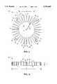
- FIG. 1is a top plan view of a heat sink device.
- FIG. 2is a side elevation view of the heat sink device of FIG. 1.
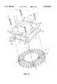
- FIG. 3is side elevation view of the heat sink device of FIG. 1, along with an associated cooling fan, mounted on an integrated circuit device to be cooled.
- FIG. 4is a top perspective exploded view showing the manner in which the cooling fan of FIG. 3 may be attached to the heat sink device of FIG. 1.
- FIG. 5is a bottom plan detail view of one of the cooling fins of the heat sink device of FIG. 1.
- FIG. 6is a top plan view of an alternative embodiment of a heat sink device.
- FIGS. 1-6in general, illustrate a cooling apparatus 10 for dissipating heat from an electronic device 100.
- the cooling apparatus 10may include a heat sink device having a central base portion 12 having a first surface 16 adapted to contact an exterior portion of the electronic device 100; a plurality of heat members 20 extending generally radially outwardly from the central base portion 12; and a plurality of air flow paths 30 extending generally radially from the central base portion 12 and defined by the plurality of heat conducting members 20.
- FIGS. 1-6also illustrate, in general, a heat sink device 10 for dissipating heat from an electronic device 100.
- the heat sink device 10may include a central base portion 12 having a first substantially planar contact surface 16 adapted to contact an exterior portion of the electronic device 100; a plurality of elongated heat conducting members 20 extending generally radially from the central base portion 12.
- the heat conducting members 20include a first surface 25 which is substantially coplanar with the central base portion contact surface 16.
- FIGS. 1 and 2illustrate a radial heat sink device 10 having a solid central region 12.
- Central region 12may also have a generally cylindrically shaped structure having an upper surface 14.
- Central region 12also has a lower surface 16, FIG. 2, which may be substantially identical to the upper surface 14.
- a hole 18may be centrally located in the central region 12, as shown, and may extend completely through the solid central region 12, connecting the central region upper and lower surfaces 14, 16. Hole 18 may be provided with threads in a conventional manner for purposes as will be discussed in more detail herein.
- Central region 12may have a diameter "a" of about 34 mm. Referring to FIG. 2, it can be seen that the heat sink device 10 may have an overall diameter "b" of about 80 mm and a height "c" of about 9 mm.
- a plurality of cooling fins 20, such as the individual fins 22, 24 and 26,may extend radially outwardly from the heat sink device central region 12.
- the cooling fins 20define a plurality of generally wedge-shaped spaces 30, such as the individual spaces 32, 34, 36, each of which is located between two adjacent fins 20.
- the heat sink device 10has been illustrated having thirty-two fins, any number of fins could alternatively be used depending upon the desired heat transfer characteristics desired.
- Some of the fins 20, such as the individual fins 38, 46, 54 and 62,may terminate in connectors, such as the connectors 40, 48, 56 and 64, respectively, FIG. 1.
- Each of the connectors 40, 48, 56 and 64may have a generally annular shape and may include a threaded opening 42, 50, 58, 68, respectively.
- the threaded openings 42, 50, 58, 68may be provided to facilitate the attachment of a fan assembly 150, FIG. 3, to the heat sink device 10 as will be explained in further detail.
- Each connector 40, 48, 56, 64may also include a gap, such as the gaps 44, 52, 60 and 66, respectively.
- the gaps 44, 52, 60 and 66result in the connector annular wall portions assuming a "c"-shaped configuration as shown in FIG. 1.
- the gaps 44, 52, 60 and 66may be provided to facilitate formation of the heat sink device 10 by an extrusion method, as will be explained in more detail herein. When other manufacturing methods, such as casting, e.g., are employed, the gaps 44, 52, 60 and 66 may be omitted. It is noted that, although the heat sink device 10 is shown in the drawing figures having four connectors 40, 48, 56, 64, a larger or smaller number may alternatively be used to facilitate attachment of the fan 150. Heat sink device 10 may be constructed of aluminum or copper or of any other material which adequately conducts heat.
- FIG. 3illustrates the heat sink device 10 mounted for use in a typical component cooling application.
- a component 100is mounted on a PC board 120.
- Component 100may be, for example, a processor such as a central processing unit for use in personal computer and work station applications.
- Component 100may be mounted to the PC board 120 via electrical connectors, such as the connectors 112, 114 in a conventional manner.
- component 100may be provided with a lid 116 which is formed from a heat conductive material such as copper in a conventional manner.
- auxiliary components 130, 140are often located in close proximity to primary components such as the primary component 100.
- Such auxiliary componentsmay be mounted to the PC Board 120 as shown, for example by the connectors 132, 134 in a conventional manner.
- the heat sink device 10may be mounted directly on top of the component lid 116 so that the lower surface 16 of the heat sink device central region 12 is in contact with the upper surface of the component lid 116, forming a joint 122 therebetween. In this manner, heat generated by the component 100 may be conducted through the component lid 116 and into the heat sink device central region 12.
- a heat conductive substancesuch as a heat conductive grease, may be applied between the lid 116 and the lower surface 16 of the heat sink device central region 12 in a conventional manner.
- Heat sink device 10may be securely fastened to the electronic component 100 by the use of a threaded stud, not shown, which is attached to and extends upwardly from the surface of the electronic component lid 116.
- the threaded studmay engage the threaded hole 18 in the heat sink device 10, FIG. 1, in order to fasten the heat sink device 10 to the electronic component 100.
- the heat sink device 10may be spun onto the electronic component threaded stud until the lower surface 16 of the heat sink device central region 12 tightly engages the upper surface of the electronic device lid 116 as shown in FIG. 3.
- the heat sink device 10may be attached to the electronic component 10 in any conventional manner.
- a fan 150may be mounted above the heat sink assembly 10 as shown.
- the fan 150may include a plurality of fan blades 152, such as the individual fan blades 154, 156. It is noted that, although for the sake of clarity, the fan 150 is illustrated in FIG. 3 as having four fan blades, the fan 150 may actually have a greater or lesser number of blades. The fan 150 may, for example have eleven blades.
- the fan blades 152may be mounted to a hub section 158 in a conventional manner.
- the hub section 158in turn, is rotatably mounted within a fan housing 160.
- the fan 150may be powered, in a conventional manner by an electric motor.
- a pair of electrical leads 178, 180may be provided to supply power to the fan electric motor, also in a conventional manner.
- the motormay, for example, be a 12 volt DC brushless type motor.
- the fanfor example, may be of the type commercially available from Matsushita Electric Company of Japan and sold as Model No. FBA06T12H.
- the fan housing 160may be provided with a plurality of through-holes 162, 164, 166, 168 as shown.
- a plurality of bolts or screws 170, 172, 174, 176may be passed through the fan through-holes 162, 164, 166, 168 and engaged with the heat sink threaded openings 42, 50, 58, 66, respectively.
- the fanmay also optionally be provided with a grill 182, FIG. 3, in order to prevent the entry of foreign objects into the fan 150 during operation.
- the grill 182may be secured with the bolts or screws 170, 172, 174, 176 as previously described or, alternatively, may be secured in any conventional manner.
- the lower surface 16 of the heat sink assembly central region 12may be tightly secured against the upper surface of the component lid 116, thus facilitating heat transfer between the two surfaces. Accordingly, during operation of the component 100, heat is drawn away from the component and into the heat sink central region 12.
- the heatafter being transferred into the heat sink central region 12, must be further transferred into the cooling fins 20 and then into the surrounding air.
- the ability of a heat sink device, such as heat sink device 10, to transfer heat into the airdepends, among other things, upon the amount of surface area of the heat sink device exposed to the surrounding air.
- the cooling fins 20facilitate such heat transfer by effectively increasing the surface area of the heat sink device 10.
- fan 150may be activated in order to cause air movement in the general direction of the arrows 142, 144, FIG. 3. Specifically, air will be forced downwardly in the direction of arrows 142, 144, and flow through the gaps 30 and over the heat sink cooling fins 20. Because the bottom of the heat sink device 10 is open, the air will then impinge directly upon the primary electronic component 100 and the auxiliary components 130, 140. At this point, the air is forced to assume a more horizontal flow pattern generally illustrated by the arrows 146, 148.
- heat sink device 10air entering the heat sink device first passes over the heat sink device cooling fins 20 in order to remove heat which has conducted into the fins from the heat sink central region 12. After passing over the fins, this same air then impinges directly upon the electronic components 100, 130, 140 in order to remove additional heat directly from the components. In this manner, the heat sink device 10 is able to remove heat from electronic components, such as the components 100, 130, 140 in a highly efficient manner.
- heat in the heat sink device central region 12is conducted into the heat sink device cooling fins 20 in only a radial direction as indicated, for example by the arrow 28 in FIG. 1.
- This radial heat conductionis enhanced by the fact that the cooling fins 20 are integrally formed with the central region 12. Due to this integral formation, there are no joints or interface surfaces within the heat flow path which might otherwise tend to impair heat conduction.
- the airflow within the heat sink device 10also occurs in a substantially radial direction as indicated by the arrows 146, 148.
- the heat sink device 10is able to cool electronic components, such as the components 100, 130, 140, FIG. 4, in two ways.
- the heat sink device 10cools the component by conducting heat away from the component into the heat sink device central region 12 and then radially into the cooling fins 20 for transfer into the air flow.
- the heat sink device 10causes air to impinge directly upon the electronic component to cause heat removal.
- the fan hub 158represents a "dead spot" within the fan. In other words, no air flow is induced by the fan in an area directly below the hub 158; airflow is only induced in an area below the fan blades 52.
- the diameter of the heat sink central region 12may be constructed to approximately correspond to the diameter of the fan hub 158. This arrangement allows the size of the heat sink central region 12 to be maximized without any significant reduction in useful cooling fin surface area.
- This increased size of the heat sink central region 12results in a larger contact surface area between the electronic component 100 and the heat sink device 10 which improves heat transfer between the two.
- the increased size of the heat sink central regionalso results in the central region having an increased mass, which improves heat conduction into the central region and away from the electronic component 100.
- each of the cooling fins 20may be tapered. Specifically, with reference to the cooling fin 24 in FIG. 5, it can be seen that each fin may have outer surfaces 70 and 72 which taper at an angle "g" of about 2 degrees to a radiused point 74. Each fin 20 may also have a length "f" of about 23 mm and an inside thickness "e", adjacent the heat sink central region 12, of about 1.8 mm. Accordingly, each fin may have an outside thickness "d", opposite the heat sink central region 12, of about 1 mm.
- the taper described aboveallows the heat sink device 10 to operate in an extremely efficient manner.
- the heat sink device fins 20will have the highest temperature at a location immediately adjacent the heat sink device central region 12, e.g., FIG. 1.
- the temperature of the finwill decrease toward the outer tip 74 of the fin, FIG. 5.
- This temperature gradientis due to the fact that heat originates in the central region 12 and then conducts radially outwardly trough the fins 20.
- the fin taper described abovecauses a greater mass of fin material to be located at regions which are closer to the central region 12 and which, thus, are required to conduct a greater amount of heat. This greater mass of material enhances heat conduction in these areas.
- the fin taperalso provides for more fin surface area in regions close to the central region 12 and, thus, facilitates the efficient transfer of heat from the fins into the surrounding air.
- each of the cooling fins 20has a lower surface, such as the lower surface 25 of the fin 24. As can be seen from FIGS. 2 and 5, the lower surface of each of the fins 20 is coplanar with the heat sink central region lower surface 16. Referring to FIG. 1, it can be seen that each of the fins 20 also have an upper surface, such as the upper surface 71 of the fin 24. As can be seen from FIG. 2, the upper surface of each of the fins 20 is coplanar with the heat sink central region upper surface 14.
- the heat sink device 10may be constructed in any conventional manner such as by die casting or investment casting processes. In a preferred method, however, the heat sink device 10 may be formed by an extrusion process. In this process, an elongated structure having a cross-section identical to that shown in FIG. 1, may be extruded. After extrusion, the elongated structure may be cut into a plurality of sections, each having a thickness equal to the desired height "c", FIG. 2, of the heat sink device. After cutting into sections, the threaded hole 18 may be provided in the central region 12 and the connector openings 42, 50, 58 and 66 may be provided with threads in a conventional manner. Alternatively, the threaded hole 18 and the threads in the connector openings 42, 50, 58 and 66 may be provided before cutting the elongated extruded structure into sections.
- the heat sink devicemay be provided with a configuration which is more conducive to extruding, such as the configuration shown in FIG. 6.
- the heat sink device 200includes a plurality of cooling fins 202 which extend radially outwardly from a central region 204 in a similar manner to the heat sink device 10.
- the heat sink device 200may also be provided with connectors 206, 208, 210 and 212 which may be identical to the connectors 40, 48, 56 and 64 of the heat sink device 10 in order to facilitate attachment of a fan in a manner as previously described.
- the heat sink device 200may, however, be provided with a reduced number of cooling fins, e.g., twenty-nine, in order to facilitate an extrusion process.
- the heat sink device 200may also be provided with a flattened area 214 which serves to support the elongated extruded structure as it exits the extrusion die.
- Flattened area 214may be formed of a plurality of fins of appropriate length, such as the fins 216, 218, 220, 222, 224.
- a mass of materialmay also be left in an area 225 located radially inwardly of the fins 216, 218, 220, 222, 224 in order to facilitate the extrusion process.
- the cooling fins immediately adjacent the connectors 206, 208, 210, 212may be shortened as shown in FIG. 6.
- shortened fins 226 and 228may be provided adjacent the connector 206
- shortened fins 230 and 232may be provided adjacent the connector 208
- shortened fins 234 and 236may be provided adjacent the connector 210
- shortened fins 238 and 240may be provided adjacent connector 212.
- the heat sink device 200 of FIG. 6may be identical to the previously described heat sink device 10.
Landscapes
- Engineering & Computer Science (AREA)
- Physics & Mathematics (AREA)
- Condensed Matter Physics & Semiconductors (AREA)
- General Physics & Mathematics (AREA)
- Computer Hardware Design (AREA)
- Microelectronics & Electronic Packaging (AREA)
- Power Engineering (AREA)
- Chemical & Material Sciences (AREA)
- Materials Engineering (AREA)
- Cooling Or The Like Of Electrical Apparatus (AREA)
- Cooling Or The Like Of Semiconductors Or Solid State Devices (AREA)
Abstract
Description
Claims (15)
Priority Applications (1)
| Application Number | Priority Date | Filing Date | Title |
|---|---|---|---|
| US08/768,906US5794685A (en) | 1996-12-17 | 1996-12-17 | Heat sink device having radial heat and airflow paths |
Applications Claiming Priority (1)
| Application Number | Priority Date | Filing Date | Title |
|---|---|---|---|
| US08/768,906US5794685A (en) | 1996-12-17 | 1996-12-17 | Heat sink device having radial heat and airflow paths |
Publications (1)
| Publication Number | Publication Date |
|---|---|
| US5794685Atrue US5794685A (en) | 1998-08-18 |
Family
ID=25083837
Family Applications (1)
| Application Number | Title | Priority Date | Filing Date |
|---|---|---|---|
| US08/768,906Expired - LifetimeUS5794685A (en) | 1996-12-17 | 1996-12-17 | Heat sink device having radial heat and airflow paths |
Country Status (1)
| Country | Link |
|---|---|
| US (1) | US5794685A (en) |
Cited By (88)
| Publication number | Priority date | Publication date | Assignee | Title |
|---|---|---|---|---|
| US6023413A (en)* | 1997-02-03 | 2000-02-08 | Nec Corporation | Cooling structure for multi-chip module |
| WO2000027177A1 (en)* | 1998-11-04 | 2000-05-11 | Zalman Tech Co., Ltd. | Heatsink for electronic component, and apparatus and method for manufacturing the same |
| USD427946S (en)* | 1999-07-26 | 2000-07-11 | Acecast Industry Co., Ltd. | Bicycle shock absorber combination radiator fin design |
| USD428857S (en)* | 1999-09-03 | 2000-08-01 | Agilent Technologies | Cooling device |
| US6109341A (en)* | 1998-04-30 | 2000-08-29 | Sanyo Denki Co., Ltd. | Electronic component cooling apparatus including elongated heat sink |
| US6157539A (en)* | 1999-08-13 | 2000-12-05 | Agilent Technologies | Cooling apparatus for electronic devices |
| US6176299B1 (en) | 1999-02-22 | 2001-01-23 | Agilent Technologies, Inc. | Cooling apparatus for electronic devices |
| US6181556B1 (en) | 1999-07-21 | 2001-01-30 | Richard K. Allman | Thermally-coupled heat dissipation apparatus for electronic devices |
| USD438515S1 (en) | 1999-09-20 | 2001-03-06 | Mitsubishi Denki Kabushiki Kaisha | Portion of heat sink |
| US6330908B1 (en)* | 2000-03-15 | 2001-12-18 | Foxconn Precision Components Co., Ltd. | Heat sink |
| US6360816B1 (en) | 1999-12-23 | 2002-03-26 | Agilent Technologies, Inc. | Cooling apparatus for electronic devices |
| WO2002047453A1 (en)* | 2000-12-08 | 2002-06-13 | Ascom Energy Systems Ag | Electronics arrangement |
| US6415852B1 (en)* | 2001-01-11 | 2002-07-09 | Foxconn Precision Components Co., Ltd. | Heat sink assembly |
| USD464938S1 (en) | 2001-07-27 | 2002-10-29 | Hewlett Packard Company | High performance cooling device |
| US6479895B1 (en) | 2001-05-18 | 2002-11-12 | Intel Corporation | High performance air cooled heat sinks used in high density packaging applications |
| WO2002093643A1 (en)* | 2001-05-15 | 2002-11-21 | Nvidia Corporation | High performance heat sink for printed circuit boards |
| US6535385B2 (en) | 2000-11-20 | 2003-03-18 | Intel Corporation | High performance heat sink configurations for use in high density packaging applications |
| US6538888B1 (en)* | 2001-09-28 | 2003-03-25 | Intel Corporation | Radial base heatsink |
| USD473529S1 (en) | 2002-04-04 | 2003-04-22 | Designs For Vision, Inc. | Heat sink for a fiber optic light source |
| US6557626B1 (en) | 2000-01-11 | 2003-05-06 | Molex Incorporated | Heat sink retainer and Heat sink assembly using same |
| USD478876S1 (en) | 2002-07-15 | 2003-08-26 | Delta Electronics Inc. | Cooler module |
| US20030189813A1 (en)* | 2000-11-20 | 2003-10-09 | Intel Corporation | High performance heat sink configurations for use in high density packaging applications |
| US6634890B2 (en)* | 2000-04-14 | 2003-10-21 | Hewlett-Packard Development Company, L.P. | Spring-loaded heat sink assembly for a circuit assembly |
| US6657862B2 (en) | 2001-09-10 | 2003-12-02 | Intel Corporation | Radial folded fin heat sinks and methods of making and using same |
| US6671172B2 (en) | 2001-09-10 | 2003-12-30 | Intel Corporation | Electronic assemblies with high capacity curved fin heat sinks |
| US6705144B2 (en) | 2001-09-10 | 2004-03-16 | Intel Corporation | Manufacturing process for a radial fin heat sink |
| US20040050536A1 (en)* | 2002-09-12 | 2004-03-18 | Michinori Watanabe | Heat-emitting element cooling apparatus |
| JP2004519854A (en)* | 2001-03-03 | 2004-07-02 | ジャルマン テック コーポレーション,リミテッド | Heat sink and heat sink device using the same |
| US20040173555A1 (en)* | 2003-03-04 | 2004-09-09 | Wilt Donald E. | Railcar draft gear housing |
| WO2004084301A1 (en)* | 2003-03-13 | 2004-09-30 | Intel Corporation | Split fin heat sink |
| US20040190248A1 (en)* | 2003-03-25 | 2004-09-30 | International Business Machines Corporation | High efficiency heat sink/air cooler system for heat-generating components |
| US6830097B2 (en) | 2002-09-27 | 2004-12-14 | Modine Manufacturing Company | Combination tower and serpentine fin heat sink device |
| US6851467B1 (en) | 1999-08-30 | 2005-02-08 | Molex Incorporated | Heat sink assembly |
| US20050047088A1 (en)* | 2003-08-27 | 2005-03-03 | Xu Li Fu | Heat dissipating device |
| WO2003105224A3 (en)* | 2002-06-06 | 2005-04-07 | Raytheon Co | Method and apparatus for cooling a portable computer |
| US20050141193A1 (en)* | 2003-12-26 | 2005-06-30 | Nidec Corporation | Heat Sink Fan and Method for Manufacturing Heat Sink That Is Used For the Heat Sink Fan |
| US6940719B1 (en)* | 2003-04-16 | 2005-09-06 | Asia Vital Component Co., Ltd. | Fan device |
| US20050257914A1 (en)* | 2004-05-07 | 2005-11-24 | Liang-Fu Huang | Skived-fin annular heat sink |
| US20060011324A1 (en)* | 2004-07-13 | 2006-01-19 | Rogers C J | Wound, louvered fin heat sink device |
| US7046515B1 (en) | 2002-06-06 | 2006-05-16 | Raytheon Company | Method and apparatus for cooling a circuit component |
| US20070014089A1 (en)* | 2005-07-18 | 2007-01-18 | Jia-Lie Huang | Radiator unit for an electronic component |
| US20070285890A1 (en)* | 2006-06-13 | 2007-12-13 | Taiwan Semiconductor Manufacturing Co., Ltd. | Method and apparatus for increasing heat dissipation of high performance integrated circuits (ic) |
| USD564460S1 (en) | 2007-01-25 | 2008-03-18 | Nidec Corporation | Heat sink fan |
| US20080080137A1 (en)* | 2006-10-02 | 2008-04-03 | Nidec Corporation | Heat sink and cooling apparatus |
| US20080089025A1 (en)* | 2004-03-30 | 2008-04-17 | Wolfgang Arno Winkler | Fan Arrangement |
| USD568829S1 (en) | 2006-10-12 | 2008-05-13 | Nidec Corporation | Heat sink |
| US20080156461A1 (en)* | 2006-12-28 | 2008-07-03 | Nidec Corporation | Heat sink fan |
| US20080180912A1 (en)* | 2007-01-15 | 2008-07-31 | Nidec Corporation | Radiator, heat sink fan, and radiator manufacturing method |
| US20080186676A1 (en)* | 2007-02-06 | 2008-08-07 | Hon Hai Precision Ind. Co., Ltd. | Electrical connector assembly |
| USD576567S1 (en) | 2007-02-13 | 2008-09-09 | Nidec Corporation | Heat sink fan |
| USD576964S1 (en)* | 2007-11-08 | 2008-09-16 | Abl Ip Holding, Llc | Heat sink |
| US20090120613A1 (en)* | 2007-11-09 | 2009-05-14 | Delta Electronics, Inc. | Heat sink |
| USD593042S1 (en) | 2008-01-31 | 2009-05-26 | Nidec Corporation | Heat sink |
| US20090218079A1 (en)* | 2008-02-29 | 2009-09-03 | Sanyo Denki Co., Ltd. | Heat-emitting element cooling apparatus |
| USD603810S1 (en)* | 2008-08-29 | 2009-11-10 | Lighthouse Technology Co., Ltd. | Heat sink for illuminating device |
| USD604255S1 (en) | 2008-10-23 | 2009-11-17 | Abl Ip Holding Llc | Heat sink |
| US20090314473A1 (en)* | 2006-09-19 | 2009-12-24 | Minoru Yoshikawa | Cooling device |
| USD613257S1 (en) | 2008-10-23 | 2010-04-06 | Abl Ip Holding Llc | Heat sink |
| USD619549S1 (en)* | 2009-07-21 | 2010-07-13 | Foxsemicon Integrated Technology, Inc. | Heat dissipation device |
| USD619548S1 (en)* | 2009-07-21 | 2010-07-13 | Foxsemicon Intergrated Technology, Inc. | Heat dissipation device |
| USD622675S1 (en)* | 2009-07-21 | 2010-08-31 | Foxsemicon Integrated Technology, Inc. | Heat dissipation device |
| US20100236765A1 (en)* | 2009-03-18 | 2010-09-23 | Fu Zhun Precision Industry (Shen Zhen) Co., Ltd. | Fan assembly and heat dissipation device having the same |
| US20110149514A1 (en)* | 2009-12-17 | 2011-06-23 | Hong Fu Jin Precision Industry (Shenzhen) Co., Ltd. | Heat dissipating device |
| USD642732S1 (en)* | 2010-03-23 | 2011-08-02 | Cooper Technologies Company | Lighting fixture |
| US20120006514A1 (en)* | 2009-03-25 | 2012-01-12 | Bratkovski Alexandre M | Grid heat sink |
| USD657089S1 (en)* | 2010-04-10 | 2012-04-03 | Lg Innotek Co., Ltd. | LED lamp |
| US20120268894A1 (en)* | 2011-04-25 | 2012-10-25 | Journee Lighting, Inc. | Socket and heat sink unit for use with removable led light module |
| US8322897B2 (en) | 2010-04-05 | 2012-12-04 | Cooper Technologies Company | Lighting assemblies having controlled directional heat transfer |
| US20130319064A1 (en)* | 2012-06-04 | 2013-12-05 | Dong Guan Yung Teng Electronic Products Co., Ltd. | Heat sink fabrication method |
| US20140247608A1 (en)* | 2011-10-02 | 2014-09-04 | Nanker(Guang Zhou)Semiconductor Manufacturing Corp. | Led photo-electric source assembly and led road lamp |
| US20140307441A1 (en)* | 2011-05-18 | 2014-10-16 | Nanker(Guang Zhou) Semiconductor Manufacturing Corp. | Dustproof and waterproof multipurpose led-light power source assembly and dustproof and waterproof led light |
| US20150289416A1 (en)* | 2013-04-02 | 2015-10-08 | Gerald Ho Kim | Silicon-based heat-dissipation device for heat-generating devices |
| US20150376820A1 (en)* | 2013-02-14 | 2015-12-31 | Grosse (Zhejiang) Machinery Co., Ltd. | Actuating device |
| US9470372B2 (en) | 2008-11-26 | 2016-10-18 | Deloren E. Anderson | High intensity replaceable light emitting diode module and array |
| US9565782B2 (en) | 2013-02-15 | 2017-02-07 | Ecosense Lighting Inc. | Field replaceable power supply cartridge |
| US9568665B2 (en) | 2015-03-03 | 2017-02-14 | Ecosense Lighting Inc. | Lighting systems including lens modules for selectable light distribution |
| USD782094S1 (en) | 2015-07-20 | 2017-03-21 | Ecosense Lighting Inc. | LED luminaire having a mounting system |
| USD782093S1 (en) | 2015-07-20 | 2017-03-21 | Ecosense Lighting Inc. | LED luminaire having a mounting system |
| USD785218S1 (en) | 2015-07-06 | 2017-04-25 | Ecosense Lighting Inc. | LED luminaire having a mounting system |
| US9651227B2 (en) | 2015-03-03 | 2017-05-16 | Ecosense Lighting Inc. | Low-profile lighting system having pivotable lighting enclosure |
| US9651216B2 (en) | 2015-03-03 | 2017-05-16 | Ecosense Lighting Inc. | Lighting systems including asymmetric lens modules for selectable light distribution |
| US9651232B1 (en) | 2015-08-03 | 2017-05-16 | Ecosense Lighting Inc. | Lighting system having a mounting device |
| US9746159B1 (en) | 2015-03-03 | 2017-08-29 | Ecosense Lighting Inc. | Lighting system having a sealing system |
| US20170269647A1 (en)* | 2016-03-21 | 2017-09-21 | Hong Fu Jin Precision Industry (Wuhan) Co., Ltd. | Heat dissipation device and electronic device using the same |
| US9869450B2 (en) | 2015-02-09 | 2018-01-16 | Ecosense Lighting Inc. | Lighting systems having a truncated parabolic- or hyperbolic-conical light reflector, or a total internal reflection lens; and having another light reflector |
| US10477636B1 (en) | 2014-10-28 | 2019-11-12 | Ecosense Lighting Inc. | Lighting systems having multiple light sources |
| US11024558B2 (en)* | 2010-03-26 | 2021-06-01 | Hamilton Sundstrand Corporation | Heat transfer device with fins defining air flow channels |
| US11306897B2 (en) | 2015-02-09 | 2022-04-19 | Ecosense Lighting Inc. | Lighting systems generating partially-collimated light emissions |
Citations (40)
| Publication number | Priority date | Publication date | Assignee | Title |
|---|---|---|---|---|
| FR1206000A (en)* | 1958-04-29 | 1960-02-05 | Silec Liaisons Elec | Cooling fin |
| US2936409A (en)* | 1956-12-13 | 1960-05-10 | Gen Electric | Current rectifier assemblies |
| US3220471A (en)* | 1963-01-15 | 1965-11-30 | Wakefield Engineering Co Inc | Heat transfer |
| US3262028A (en)* | 1962-04-17 | 1966-07-19 | Harold B Hermann | Electrical component mounting device |
| US3366171A (en)* | 1966-07-14 | 1968-01-30 | Bbc Brown Boveri & Cie | Heat sink for semi-conductor elements |
| US3566958A (en)* | 1968-12-18 | 1971-03-02 | Gen Systems Inc | Heat sink for electrical devices |
| US3686533A (en)* | 1970-08-04 | 1972-08-22 | Lannionaise D Electronique Soc | Heat sink mounting arrangement for integrated circuits |
| US3727114A (en)* | 1971-08-03 | 1973-04-10 | Mitsubishi Electric Corp | Air cooled semiconductor stack |
| DE2743708A1 (en)* | 1977-09-28 | 1979-04-05 | Siemens Ag | Heat sink for hermetically sealed equipment - has modular heat exchanger and fan as part of housing wall |
| US4194556A (en)* | 1978-01-13 | 1980-03-25 | Toyota Jidosha Kogyo Kabushiki Kaisha | Cooling apparatus for an internal combustion engine |
| US4233644A (en)* | 1979-06-28 | 1980-11-11 | International Business Machines Corporation | Dual-pull air cooling for a computer frame |
| US4489363A (en)* | 1983-01-31 | 1984-12-18 | Sperry Corporation | Apparatus for cooling integrated circuit chips |
| US4541004A (en)* | 1982-11-24 | 1985-09-10 | Burroughs Corporation | Aerodynamically enhanced heat sink |
| US4546405A (en)* | 1983-05-25 | 1985-10-08 | International Business Machines Corporation | Heat sink for electronic package |
| US4611238A (en)* | 1982-05-05 | 1986-09-09 | Burroughs Corporation | Integrated circuit package incorporating low-stress omnidirectional heat sink |
| US4620216A (en)* | 1983-04-29 | 1986-10-28 | International Business Machines Corporation | Unitary slotted heat sink for semiconductor packages |
| US4639829A (en)* | 1984-06-29 | 1987-01-27 | International Business Machines Corporation | Thermal conduction disc-chip cooling enhancement means |
| US4662830A (en)* | 1985-09-06 | 1987-05-05 | Magnetic Peripherals Inc. | Quiet centrifugal fan |
| US4682651A (en)* | 1986-09-08 | 1987-07-28 | Burroughs Corporation (Now Unisys Corporation) | Segmented heat sink device |
| US4715430A (en)* | 1986-10-27 | 1987-12-29 | International Business Machines Corporation | Environmentally secure and thermally efficient heat sink assembly |
| US4733293A (en)* | 1987-02-13 | 1988-03-22 | Unisys Corporation | Heat sink device assembly for encumbered IC package |
| JPS63113460A (en)* | 1986-09-02 | 1988-05-18 | イ−ストマン・コダック・カンパニ− | Re-usable electronic photographic element |
| US4812733A (en)* | 1987-10-27 | 1989-03-14 | Richard Tobey | Computer element performance enhancer |
| US4970579A (en)* | 1988-09-21 | 1990-11-13 | International Business Machines Corp. | Integrated circuit package with improved cooling means |
| JPH02286900A (en)* | 1989-04-28 | 1990-11-27 | Hitachi Ltd | Fan mounting structure |
| US5000254A (en)* | 1989-06-20 | 1991-03-19 | Digital Equipment Corporation | Dynamic heat sink |
| US5019880A (en)* | 1988-01-07 | 1991-05-28 | Prime Computer, Inc. | Heat sink apparatus |
| US5029236A (en)* | 1989-05-10 | 1991-07-02 | Sony Corporation | Radiotelephone apparatus |
| JPH03229492A (en)* | 1990-02-05 | 1991-10-11 | Seiko Electronic Components Ltd | Centrifugal blower |
| US5191330A (en)* | 1990-12-12 | 1993-03-02 | Northern Telecom Limited | Binary for penternary (five-level) encoding system |
| WO1993008600A1 (en)* | 1991-10-15 | 1993-04-29 | Velox Computer Technology, Inc. | Intrinsically controlled cooling container |
| US5272599A (en)* | 1993-03-19 | 1993-12-21 | Compaq Computer Corporation | Microprocessor heat dissipation apparatus for a printed circuit board |
| US5287249A (en)* | 1993-07-07 | 1994-02-15 | Global Win Technology Co., Ltd. | Fin assembly for an integrated circuit |
| US5288203A (en)* | 1992-10-23 | 1994-02-22 | Thomas Daniel L | Low profile fan body with heat transfer characteristics |
| US5297617A (en)* | 1992-12-22 | 1994-03-29 | Edward Herbert | Fan assembly with heat sink |
| US5299632A (en)* | 1993-02-19 | 1994-04-05 | Lee Lien Jung | Fin device for an integrated circuit |
| US5309983A (en)* | 1992-06-23 | 1994-05-10 | Pcubid Computer Technology Inc. | Low profile integrated heat sink and fan assembly |
| US5335722A (en)* | 1993-09-30 | 1994-08-09 | Global Win Technology Co., Ltd | Cooling assembly for an integrated circuit |
| US5353863A (en)* | 1994-03-07 | 1994-10-11 | Yu Chi T | Pentium CPU cooling device |
| US5484262A (en)* | 1992-10-23 | 1996-01-16 | Nidec Corporation | Low profile fan body with heat transfer characteristics |
- 1996
- 1996-12-17USUS08/768,906patent/US5794685A/ennot_activeExpired - Lifetime
Patent Citations (41)
| Publication number | Priority date | Publication date | Assignee | Title |
|---|---|---|---|---|
| US2936409A (en)* | 1956-12-13 | 1960-05-10 | Gen Electric | Current rectifier assemblies |
| FR1206000A (en)* | 1958-04-29 | 1960-02-05 | Silec Liaisons Elec | Cooling fin |
| US3262028A (en)* | 1962-04-17 | 1966-07-19 | Harold B Hermann | Electrical component mounting device |
| US3220471A (en)* | 1963-01-15 | 1965-11-30 | Wakefield Engineering Co Inc | Heat transfer |
| US3366171A (en)* | 1966-07-14 | 1968-01-30 | Bbc Brown Boveri & Cie | Heat sink for semi-conductor elements |
| US3566958A (en)* | 1968-12-18 | 1971-03-02 | Gen Systems Inc | Heat sink for electrical devices |
| US3686533A (en)* | 1970-08-04 | 1972-08-22 | Lannionaise D Electronique Soc | Heat sink mounting arrangement for integrated circuits |
| US3727114A (en)* | 1971-08-03 | 1973-04-10 | Mitsubishi Electric Corp | Air cooled semiconductor stack |
| DE2743708A1 (en)* | 1977-09-28 | 1979-04-05 | Siemens Ag | Heat sink for hermetically sealed equipment - has modular heat exchanger and fan as part of housing wall |
| US4194556A (en)* | 1978-01-13 | 1980-03-25 | Toyota Jidosha Kogyo Kabushiki Kaisha | Cooling apparatus for an internal combustion engine |
| US4233644A (en)* | 1979-06-28 | 1980-11-11 | International Business Machines Corporation | Dual-pull air cooling for a computer frame |
| US4611238A (en)* | 1982-05-05 | 1986-09-09 | Burroughs Corporation | Integrated circuit package incorporating low-stress omnidirectional heat sink |
| US4541004A (en)* | 1982-11-24 | 1985-09-10 | Burroughs Corporation | Aerodynamically enhanced heat sink |
| US4489363A (en)* | 1983-01-31 | 1984-12-18 | Sperry Corporation | Apparatus for cooling integrated circuit chips |
| US4620216A (en)* | 1983-04-29 | 1986-10-28 | International Business Machines Corporation | Unitary slotted heat sink for semiconductor packages |
| US4546405A (en)* | 1983-05-25 | 1985-10-08 | International Business Machines Corporation | Heat sink for electronic package |
| US4639829A (en)* | 1984-06-29 | 1987-01-27 | International Business Machines Corporation | Thermal conduction disc-chip cooling enhancement means |
| US4662830A (en)* | 1985-09-06 | 1987-05-05 | Magnetic Peripherals Inc. | Quiet centrifugal fan |
| JPS63113460A (en)* | 1986-09-02 | 1988-05-18 | イ−ストマン・コダック・カンパニ− | Re-usable electronic photographic element |
| US4682651A (en)* | 1986-09-08 | 1987-07-28 | Burroughs Corporation (Now Unisys Corporation) | Segmented heat sink device |
| US4715430A (en)* | 1986-10-27 | 1987-12-29 | International Business Machines Corporation | Environmentally secure and thermally efficient heat sink assembly |
| US4733293A (en)* | 1987-02-13 | 1988-03-22 | Unisys Corporation | Heat sink device assembly for encumbered IC package |
| US4812733A (en)* | 1987-10-27 | 1989-03-14 | Richard Tobey | Computer element performance enhancer |
| US5019880A (en)* | 1988-01-07 | 1991-05-28 | Prime Computer, Inc. | Heat sink apparatus |
| US4970579A (en)* | 1988-09-21 | 1990-11-13 | International Business Machines Corp. | Integrated circuit package with improved cooling means |
| JPH02286900A (en)* | 1989-04-28 | 1990-11-27 | Hitachi Ltd | Fan mounting structure |
| US5029236A (en)* | 1989-05-10 | 1991-07-02 | Sony Corporation | Radiotelephone apparatus |
| US5000254A (en)* | 1989-06-20 | 1991-03-19 | Digital Equipment Corporation | Dynamic heat sink |
| JPH03229492A (en)* | 1990-02-05 | 1991-10-11 | Seiko Electronic Components Ltd | Centrifugal blower |
| US5191330A (en)* | 1990-12-12 | 1993-03-02 | Northern Telecom Limited | Binary for penternary (five-level) encoding system |
| WO1993008600A1 (en)* | 1991-10-15 | 1993-04-29 | Velox Computer Technology, Inc. | Intrinsically controlled cooling container |
| US5309983A (en)* | 1992-06-23 | 1994-05-10 | Pcubid Computer Technology Inc. | Low profile integrated heat sink and fan assembly |
| US5309983B1 (en)* | 1992-06-23 | 1997-02-04 | Pcubid Computer Tech | Low profile integrated heat sink and fan assembly |
| US5288203A (en)* | 1992-10-23 | 1994-02-22 | Thomas Daniel L | Low profile fan body with heat transfer characteristics |
| US5484262A (en)* | 1992-10-23 | 1996-01-16 | Nidec Corporation | Low profile fan body with heat transfer characteristics |
| US5297617A (en)* | 1992-12-22 | 1994-03-29 | Edward Herbert | Fan assembly with heat sink |
| US5299632A (en)* | 1993-02-19 | 1994-04-05 | Lee Lien Jung | Fin device for an integrated circuit |
| US5272599A (en)* | 1993-03-19 | 1993-12-21 | Compaq Computer Corporation | Microprocessor heat dissipation apparatus for a printed circuit board |
| US5287249A (en)* | 1993-07-07 | 1994-02-15 | Global Win Technology Co., Ltd. | Fin assembly for an integrated circuit |
| US5335722A (en)* | 1993-09-30 | 1994-08-09 | Global Win Technology Co., Ltd | Cooling assembly for an integrated circuit |
| US5353863A (en)* | 1994-03-07 | 1994-10-11 | Yu Chi T | Pentium CPU cooling device |
Non-Patent Citations (1)
| Title |
|---|
| R. Mitchell, the Experimental Step 486/50 Redefines Cool. BYTE, Dec. 1990.* |
Cited By (141)
| Publication number | Priority date | Publication date | Assignee | Title |
|---|---|---|---|---|
| US6023413A (en)* | 1997-02-03 | 2000-02-08 | Nec Corporation | Cooling structure for multi-chip module |
| US6109341A (en)* | 1998-04-30 | 2000-08-29 | Sanyo Denki Co., Ltd. | Electronic component cooling apparatus including elongated heat sink |
| WO2000027177A1 (en)* | 1998-11-04 | 2000-05-11 | Zalman Tech Co., Ltd. | Heatsink for electronic component, and apparatus and method for manufacturing the same |
| RU2217886C2 (en)* | 1998-11-04 | 2003-11-27 | Залман Тек Ко., Лтд. | Electronic component heat sink, its manufacturing device and method |
| US6176299B1 (en) | 1999-02-22 | 2001-01-23 | Agilent Technologies, Inc. | Cooling apparatus for electronic devices |
| US6181556B1 (en) | 1999-07-21 | 2001-01-30 | Richard K. Allman | Thermally-coupled heat dissipation apparatus for electronic devices |
| USD427946S (en)* | 1999-07-26 | 2000-07-11 | Acecast Industry Co., Ltd. | Bicycle shock absorber combination radiator fin design |
| US6157539A (en)* | 1999-08-13 | 2000-12-05 | Agilent Technologies | Cooling apparatus for electronic devices |
| US6851467B1 (en) | 1999-08-30 | 2005-02-08 | Molex Incorporated | Heat sink assembly |
| USD428857S (en)* | 1999-09-03 | 2000-08-01 | Agilent Technologies | Cooling device |
| USD438515S1 (en) | 1999-09-20 | 2001-03-06 | Mitsubishi Denki Kabushiki Kaisha | Portion of heat sink |
| US6360816B1 (en) | 1999-12-23 | 2002-03-26 | Agilent Technologies, Inc. | Cooling apparatus for electronic devices |
| US6557626B1 (en) | 2000-01-11 | 2003-05-06 | Molex Incorporated | Heat sink retainer and Heat sink assembly using same |
| US6330908B1 (en)* | 2000-03-15 | 2001-12-18 | Foxconn Precision Components Co., Ltd. | Heat sink |
| US6634890B2 (en)* | 2000-04-14 | 2003-10-21 | Hewlett-Packard Development Company, L.P. | Spring-loaded heat sink assembly for a circuit assembly |
| US20030189813A1 (en)* | 2000-11-20 | 2003-10-09 | Intel Corporation | High performance heat sink configurations for use in high density packaging applications |
| US6633484B1 (en)* | 2000-11-20 | 2003-10-14 | Intel Corporation | Heat-dissipating devices, systems, and methods with small footprint |
| US6535385B2 (en) | 2000-11-20 | 2003-03-18 | Intel Corporation | High performance heat sink configurations for use in high density packaging applications |
| US6845010B2 (en) | 2000-11-20 | 2005-01-18 | Intel Corporation | High performance heat sink configurations for use in high density packaging applications |
| WO2002047453A1 (en)* | 2000-12-08 | 2002-06-13 | Ascom Energy Systems Ag | Electronics arrangement |
| US20050122682A1 (en)* | 2000-12-08 | 2005-06-09 | Robert Streit | Electronics arrangement |
| US6415852B1 (en)* | 2001-01-11 | 2002-07-09 | Foxconn Precision Components Co., Ltd. | Heat sink assembly |
| JP2004519854A (en)* | 2001-03-03 | 2004-07-02 | ジャルマン テック コーポレーション,リミテッド | Heat sink and heat sink device using the same |
| EP1393369A4 (en)* | 2001-05-15 | 2006-08-23 | Nvidia Corp | High performance heat sink for printed circuit boards |
| WO2002093643A1 (en)* | 2001-05-15 | 2002-11-21 | Nvidia Corporation | High performance heat sink for printed circuit boards |
| US6778390B2 (en) | 2001-05-15 | 2004-08-17 | Nvidia Corporation | High-performance heat sink for printed circuit boards |
| WO2002095823A3 (en)* | 2001-05-18 | 2003-06-19 | Intel Corp | High performance air cooled heat sinks used in high density packaging applications |
| CN100403529C (en)* | 2001-05-18 | 2008-07-16 | 英特尔公司 | High performance air cooled heat sinks used in high density packaging applications |
| US6479895B1 (en) | 2001-05-18 | 2002-11-12 | Intel Corporation | High performance air cooled heat sinks used in high density packaging applications |
| USD464938S1 (en) | 2001-07-27 | 2002-10-29 | Hewlett Packard Company | High performance cooling device |
| USD471523S1 (en) | 2001-07-27 | 2003-03-11 | Shankar Hegde | High performance cooling device |
| USD471881S1 (en) | 2001-07-27 | 2003-03-18 | Shankar Hegde | High performance cooling device |
| US20040045163A1 (en)* | 2001-09-10 | 2004-03-11 | Intel Corporation | Electronic assemblies with high capacity heat sinks and methods of manufacture |
| US20040080914A1 (en)* | 2001-09-10 | 2004-04-29 | Intel Corporation. | Electronic assemblies with high capacity heat sinks |
| US6705144B2 (en) | 2001-09-10 | 2004-03-16 | Intel Corporation | Manufacturing process for a radial fin heat sink |
| US6671172B2 (en) | 2001-09-10 | 2003-12-30 | Intel Corporation | Electronic assemblies with high capacity curved fin heat sinks |
| US6657862B2 (en) | 2001-09-10 | 2003-12-02 | Intel Corporation | Radial folded fin heat sinks and methods of making and using same |
| US7200934B2 (en) | 2001-09-10 | 2007-04-10 | Intel Corporation | Electronic assemblies with high capacity heat sinks and methods of manufacture |
| US7120020B2 (en) | 2001-09-10 | 2006-10-10 | Intel Corporation | Electronic assemblies with high capacity bent fin heat sinks |
| US7911790B2 (en) | 2001-09-10 | 2011-03-22 | Intel Corporation | Electronic assemblies with high capacity curved and bent fin heat sinks and associated methods |
| US20050280992A1 (en)* | 2001-09-10 | 2005-12-22 | Intel Corporation | Electronic assemblies with high capacity curved and bent fin heat sinks and associated methods |
| US6538888B1 (en)* | 2001-09-28 | 2003-03-25 | Intel Corporation | Radial base heatsink |
| USD473529S1 (en) | 2002-04-04 | 2003-04-22 | Designs For Vision, Inc. | Heat sink for a fiber optic light source |
| US7046515B1 (en) | 2002-06-06 | 2006-05-16 | Raytheon Company | Method and apparatus for cooling a circuit component |
| US20050280988A1 (en)* | 2002-06-06 | 2005-12-22 | Raytheon Company, A Delaware Corporation | Method and apparatus for cooling a portable computer |
| WO2003105224A3 (en)* | 2002-06-06 | 2005-04-07 | Raytheon Co | Method and apparatus for cooling a portable computer |
| US7130189B2 (en) | 2002-06-06 | 2006-10-31 | Raytheon Company | Method and apparatus for cooling a portable computer |
| CN100397631C (en)* | 2002-06-06 | 2008-06-25 | 雷西昂公司 | Method and apparatus for cooling a portable computer |
| US20060198105A1 (en)* | 2002-06-06 | 2006-09-07 | Raytheon Company | Method and Apparatus for Cooling a Circuit Component |
| US6972950B1 (en) | 2002-06-06 | 2005-12-06 | Raytheon Company | Method and apparatus for cooling a portable computer |
| US8665595B2 (en) | 2002-06-06 | 2014-03-04 | Ol Security Limited Liability Company | Method and apparatus for cooling a circuit component |
| USD478876S1 (en) | 2002-07-15 | 2003-08-26 | Delta Electronics Inc. | Cooler module |
| US6927979B2 (en)* | 2002-09-12 | 2005-08-09 | Sanyo Denki Co., Ltd. | Heat-emitting element cooling apparatus |
| US20050168946A1 (en)* | 2002-09-12 | 2005-08-04 | Sanyo Denki Co., Ltd. | Heat-emitting element cooling apparatus |
| US20040050536A1 (en)* | 2002-09-12 | 2004-03-18 | Michinori Watanabe | Heat-emitting element cooling apparatus |
| US7170746B2 (en) | 2002-09-12 | 2007-01-30 | Sanyo Denki Co., Ltd. | Heat-emitting element cooling apparatus |
| US6830097B2 (en) | 2002-09-27 | 2004-12-14 | Modine Manufacturing Company | Combination tower and serpentine fin heat sink device |
| US20040173555A1 (en)* | 2003-03-04 | 2004-09-09 | Wilt Donald E. | Railcar draft gear housing |
| US20040240182A1 (en)* | 2003-03-13 | 2004-12-02 | Shah Ketan R. | Method of making split fin heat sink |
| CN1757107B (en)* | 2003-03-13 | 2011-02-09 | 英特尔公司 | split fin radiator |
| US7188418B2 (en)* | 2003-03-13 | 2007-03-13 | Intel Corporation | Method of making split fin heat sink |
| WO2004084301A1 (en)* | 2003-03-13 | 2004-09-30 | Intel Corporation | Split fin heat sink |
| US20040190248A1 (en)* | 2003-03-25 | 2004-09-30 | International Business Machines Corporation | High efficiency heat sink/air cooler system for heat-generating components |
| US6816374B2 (en) | 2003-03-25 | 2004-11-09 | International Business Machines Corporation | High efficiency heat sink/air cooler system for heat-generating components |
| US6940719B1 (en)* | 2003-04-16 | 2005-09-06 | Asia Vital Component Co., Ltd. | Fan device |
| US20050047088A1 (en)* | 2003-08-27 | 2005-03-03 | Xu Li Fu | Heat dissipating device |
| US7193849B2 (en)* | 2003-08-27 | 2007-03-20 | Fu Zhun Precision Ind. (Shenzhen) Co., Ltd. | Heat dissipating device |
| US7123483B2 (en) | 2003-12-26 | 2006-10-17 | Nidec Corporation | Heat sink fan and method for manufacturing heat sink that is used for the heat sink fan |
| US20050141193A1 (en)* | 2003-12-26 | 2005-06-30 | Nidec Corporation | Heat Sink Fan and Method for Manufacturing Heat Sink That Is Used For the Heat Sink Fan |
| US8801375B2 (en)* | 2004-03-30 | 2014-08-12 | EBM-Pabst St. Georgen GmbH & Co. KG | Fan arrangement |
| US20080089025A1 (en)* | 2004-03-30 | 2008-04-17 | Wolfgang Arno Winkler | Fan Arrangement |
| US20050257914A1 (en)* | 2004-05-07 | 2005-11-24 | Liang-Fu Huang | Skived-fin annular heat sink |
| US20060011324A1 (en)* | 2004-07-13 | 2006-01-19 | Rogers C J | Wound, louvered fin heat sink device |
| US20070014089A1 (en)* | 2005-07-18 | 2007-01-18 | Jia-Lie Huang | Radiator unit for an electronic component |
| US20070285890A1 (en)* | 2006-06-13 | 2007-12-13 | Taiwan Semiconductor Manufacturing Co., Ltd. | Method and apparatus for increasing heat dissipation of high performance integrated circuits (ic) |
| US7583502B2 (en)* | 2006-06-13 | 2009-09-01 | Taiwan Semiconductor Manufacturing Co., Ltd. | Method and apparatus for increasing heat dissipation of high performance integrated circuits (IC) |
| US8432695B2 (en)* | 2006-09-19 | 2013-04-30 | Nec Corporation | Cooling device |
| US20090314473A1 (en)* | 2006-09-19 | 2009-12-24 | Minoru Yoshikawa | Cooling device |
| US20080080137A1 (en)* | 2006-10-02 | 2008-04-03 | Nidec Corporation | Heat sink and cooling apparatus |
| US7623348B2 (en) | 2006-10-02 | 2009-11-24 | Nidec Corporation | Heat sink and cooling apparatus |
| USD568829S1 (en) | 2006-10-12 | 2008-05-13 | Nidec Corporation | Heat sink |
| US8210241B2 (en) | 2006-12-28 | 2012-07-03 | Nidec Corporation | Heat sink fan |
| US20080156461A1 (en)* | 2006-12-28 | 2008-07-03 | Nidec Corporation | Heat sink fan |
| US20080180912A1 (en)* | 2007-01-15 | 2008-07-31 | Nidec Corporation | Radiator, heat sink fan, and radiator manufacturing method |
| US8256258B2 (en)* | 2007-01-15 | 2012-09-04 | Nidec Corporation | Radiator, heat sink fan, and radiator manufacturing method |
| USD564460S1 (en) | 2007-01-25 | 2008-03-18 | Nidec Corporation | Heat sink fan |
| US7414840B1 (en)* | 2007-02-06 | 2008-08-19 | Hon Hai Precision Ind. Co., Ltd. | Electrical connector assembly |
| US20080186676A1 (en)* | 2007-02-06 | 2008-08-07 | Hon Hai Precision Ind. Co., Ltd. | Electrical connector assembly |
| USD576567S1 (en) | 2007-02-13 | 2008-09-09 | Nidec Corporation | Heat sink fan |
| USD576964S1 (en)* | 2007-11-08 | 2008-09-16 | Abl Ip Holding, Llc | Heat sink |
| US20090120613A1 (en)* | 2007-11-09 | 2009-05-14 | Delta Electronics, Inc. | Heat sink |
| USD593042S1 (en) | 2008-01-31 | 2009-05-26 | Nidec Corporation | Heat sink |
| US20090218079A1 (en)* | 2008-02-29 | 2009-09-03 | Sanyo Denki Co., Ltd. | Heat-emitting element cooling apparatus |
| USD603810S1 (en)* | 2008-08-29 | 2009-11-10 | Lighthouse Technology Co., Ltd. | Heat sink for illuminating device |
| USD613257S1 (en) | 2008-10-23 | 2010-04-06 | Abl Ip Holding Llc | Heat sink |
| USD604255S1 (en) | 2008-10-23 | 2009-11-17 | Abl Ip Holding Llc | Heat sink |
| US9470372B2 (en) | 2008-11-26 | 2016-10-18 | Deloren E. Anderson | High intensity replaceable light emitting diode module and array |
| US12219678B2 (en) | 2008-11-26 | 2025-02-04 | In 2 Developments Llc | High intensity replaceable light emitting diode module and array |
| US10925139B2 (en) | 2008-11-26 | 2021-02-16 | Yjb Led, Inc. | High intensity replaceable light emitting diode module and array |
| US11178744B2 (en) | 2008-11-26 | 2021-11-16 | Yjb Led, Inc. | High intensity replaceable light emitting diode module and array |
| US11924943B2 (en) | 2008-11-26 | 2024-03-05 | Yjb Led, Inc. | High intensity replaceable light emitting diode module and array |
| US20100236765A1 (en)* | 2009-03-18 | 2010-09-23 | Fu Zhun Precision Industry (Shen Zhen) Co., Ltd. | Fan assembly and heat dissipation device having the same |
| US20120006514A1 (en)* | 2009-03-25 | 2012-01-12 | Bratkovski Alexandre M | Grid heat sink |
| USD619548S1 (en)* | 2009-07-21 | 2010-07-13 | Foxsemicon Intergrated Technology, Inc. | Heat dissipation device |
| USD619549S1 (en)* | 2009-07-21 | 2010-07-13 | Foxsemicon Integrated Technology, Inc. | Heat dissipation device |
| USD622675S1 (en)* | 2009-07-21 | 2010-08-31 | Foxsemicon Integrated Technology, Inc. | Heat dissipation device |
| US20110149514A1 (en)* | 2009-12-17 | 2011-06-23 | Hong Fu Jin Precision Industry (Shenzhen) Co., Ltd. | Heat dissipating device |
| US8199502B2 (en)* | 2009-12-17 | 2012-06-12 | Hong Fu Jin Precision Industry (Shenzhen) Co., Ltd. | Heat dissipating device |
| USD657491S1 (en) | 2010-03-23 | 2012-04-10 | Cooper Technologies Company | Lighting fixture |
| USD664291S1 (en) | 2010-03-23 | 2012-07-24 | Cooper Technologies Company | Lighting fixture |
| USD657908S1 (en) | 2010-03-23 | 2012-04-17 | Cooper Technologies Company | Lighting fixture |
| USD657490S1 (en) | 2010-03-23 | 2012-04-10 | Cooper Technologies Company | Lighting fixture |
| USD657492S1 (en) | 2010-03-23 | 2012-04-10 | Cooper Technologies Company | Lighting fixture |
| USD642732S1 (en)* | 2010-03-23 | 2011-08-02 | Cooper Technologies Company | Lighting fixture |
| US11024558B2 (en)* | 2010-03-26 | 2021-06-01 | Hamilton Sundstrand Corporation | Heat transfer device with fins defining air flow channels |
| US8322897B2 (en) | 2010-04-05 | 2012-12-04 | Cooper Technologies Company | Lighting assemblies having controlled directional heat transfer |
| US8545064B2 (en) | 2010-04-05 | 2013-10-01 | Cooper Technologies Company | Lighting assemblies having controlled directional heat transfer |
| USD657089S1 (en)* | 2010-04-10 | 2012-04-03 | Lg Innotek Co., Ltd. | LED lamp |
| US20120268894A1 (en)* | 2011-04-25 | 2012-10-25 | Journee Lighting, Inc. | Socket and heat sink unit for use with removable led light module |
| US9476581B2 (en)* | 2011-05-18 | 2016-10-25 | Nanker (Guang Zhou) Semiconductor Manufacturing Corp. | Dustproof and waterproof multipurpose LED-light power source assembly and dustproof and waterproof LED light |
| US20140307441A1 (en)* | 2011-05-18 | 2014-10-16 | Nanker(Guang Zhou) Semiconductor Manufacturing Corp. | Dustproof and waterproof multipurpose led-light power source assembly and dustproof and waterproof led light |
| US9714762B2 (en)* | 2011-10-02 | 2017-07-25 | Nanker(Guang Zhou)Semiconductor Manufacturing Corp. | LED photo-electric source assembly and LED road lamp |
| US20140247608A1 (en)* | 2011-10-02 | 2014-09-04 | Nanker(Guang Zhou)Semiconductor Manufacturing Corp. | Led photo-electric source assembly and led road lamp |
| US20130319064A1 (en)* | 2012-06-04 | 2013-12-05 | Dong Guan Yung Teng Electronic Products Co., Ltd. | Heat sink fabrication method |
| US20150376820A1 (en)* | 2013-02-14 | 2015-12-31 | Grosse (Zhejiang) Machinery Co., Ltd. | Actuating device |
| US9565782B2 (en) | 2013-02-15 | 2017-02-07 | Ecosense Lighting Inc. | Field replaceable power supply cartridge |
| US20150289416A1 (en)* | 2013-04-02 | 2015-10-08 | Gerald Ho Kim | Silicon-based heat-dissipation device for heat-generating devices |
| US9167723B1 (en)* | 2013-04-02 | 2015-10-20 | Gerald Ho Kim | Silicon-based heat-dissipation device for heat-generating devices |
| US10477636B1 (en) | 2014-10-28 | 2019-11-12 | Ecosense Lighting Inc. | Lighting systems having multiple light sources |
| US9869450B2 (en) | 2015-02-09 | 2018-01-16 | Ecosense Lighting Inc. | Lighting systems having a truncated parabolic- or hyperbolic-conical light reflector, or a total internal reflection lens; and having another light reflector |
| US11614217B2 (en) | 2015-02-09 | 2023-03-28 | Korrus, Inc. | Lighting systems generating partially-collimated light emissions |
| US11306897B2 (en) | 2015-02-09 | 2022-04-19 | Ecosense Lighting Inc. | Lighting systems generating partially-collimated light emissions |
| US9568665B2 (en) | 2015-03-03 | 2017-02-14 | Ecosense Lighting Inc. | Lighting systems including lens modules for selectable light distribution |
| US9746159B1 (en) | 2015-03-03 | 2017-08-29 | Ecosense Lighting Inc. | Lighting system having a sealing system |
| US9651216B2 (en) | 2015-03-03 | 2017-05-16 | Ecosense Lighting Inc. | Lighting systems including asymmetric lens modules for selectable light distribution |
| US9651227B2 (en) | 2015-03-03 | 2017-05-16 | Ecosense Lighting Inc. | Low-profile lighting system having pivotable lighting enclosure |
| USD785218S1 (en) | 2015-07-06 | 2017-04-25 | Ecosense Lighting Inc. | LED luminaire having a mounting system |
| USD782093S1 (en) | 2015-07-20 | 2017-03-21 | Ecosense Lighting Inc. | LED luminaire having a mounting system |
| USD782094S1 (en) | 2015-07-20 | 2017-03-21 | Ecosense Lighting Inc. | LED luminaire having a mounting system |
| US9651232B1 (en) | 2015-08-03 | 2017-05-16 | Ecosense Lighting Inc. | Lighting system having a mounting device |
| US20170269647A1 (en)* | 2016-03-21 | 2017-09-21 | Hong Fu Jin Precision Industry (Wuhan) Co., Ltd. | Heat dissipation device and electronic device using the same |
Similar Documents
| Publication | Publication Date | Title |
|---|---|---|
| US5794685A (en) | Heat sink device having radial heat and airflow paths | |
| US6401808B1 (en) | Cooling apparatus for electronic devices and method | |
| US5785116A (en) | Fan assisted heat sink device | |
| US6986384B2 (en) | Cooling apparatus for dissipating heat from a heat source | |
| US5484262A (en) | Low profile fan body with heat transfer characteristics | |
| US8205666B2 (en) | Heat sinks and method of formation | |
| US7120020B2 (en) | Electronic assemblies with high capacity bent fin heat sinks | |
| KR100334043B1 (en) | Heatsink | |
| US7509997B2 (en) | Heat sink | |
| JP3278809B2 (en) | Foldable fin-shaped heat sink and heat exchanger using the same | |
| US6501652B2 (en) | Heat sink and information processor using it | |
| US6702000B2 (en) | Heat sink apparatus, blower for use therein and electronic equipment using the same apparatus | |
| US6157539A (en) | Cooling apparatus for electronic devices | |
| US6769175B2 (en) | Heat sink device manufacture | |
| US6698499B1 (en) | Cooling device and method | |
| US6631756B1 (en) | High performance passive cooling device with ducting | |
| US5690468A (en) | Fan assembly for an integrated circuit | |
| US6816374B2 (en) | High efficiency heat sink/air cooler system for heat-generating components | |
| JPH08321571A (en) | Heat sink device | |
| US6109341A (en) | Electronic component cooling apparatus including elongated heat sink | |
| US6186739B1 (en) | Support for a cooling fan | |
| KR200290411Y1 (en) | Heat Dissipating Device For A CPU | |
| GB2348277A (en) | A fan assisted heat sink cooling device |
Legal Events
| Date | Code | Title | Description |
|---|---|---|---|
| AS | Assignment | Owner name:HEWLETT-PACKARD COMPANY, CALIFORNIA Free format text:ASSIGNMENT OF ASSIGNORS INTEREST;ASSIGNOR:DEAN, RONALD P.;REEL/FRAME:008456/0012 Effective date:19961213 | |
| STCF | Information on status: patent grant | Free format text:PATENTED CASE | |
| AS | Assignment | Owner name:HEWLETT-PACKARD COMPANY, COLORADO Free format text:MERGER;ASSIGNOR:HEWLETT-PACKARD COMPANY;REEL/FRAME:011523/0469 Effective date:19980520 | |
| FEPP | Fee payment procedure | Free format text:PAYOR NUMBER ASSIGNED (ORIGINAL EVENT CODE: ASPN); ENTITY STATUS OF PATENT OWNER: LARGE ENTITY | |
| REFU | Refund | Free format text:REFUND - PAYMENT OF MAINTENANCE FEE, 4TH YEAR, LARGE ENTITY (ORIGINAL EVENT CODE: R183); ENTITY STATUS OF PATENT OWNER: LARGE ENTITY | |
| FPAY | Fee payment | Year of fee payment:4 | |
| REMI | Maintenance fee reminder mailed | ||
| FPAY | Fee payment | Year of fee payment:8 | |
| FPAY | Fee payment | Year of fee payment:12 | |
| AS | Assignment | Owner name:HEWLETT-PACKARD DEVELOPMENT COMPANY, L.P., TEXAS Free format text:ASSIGNMENT OF ASSIGNORS INTEREST;ASSIGNOR:HEWLETT-PACKARD COMPANY;REEL/FRAME:026945/0699 Effective date:20030131 |