US5794543A - Modular pallet system - Google Patents
Modular pallet systemDownload PDFInfo
- Publication number
- US5794543A US5794543AUS08/562,507US56250795AUS5794543AUS 5794543 AUS5794543 AUS 5794543AUS 56250795 AUS56250795 AUS 56250795AUS 5794543 AUS5794543 AUS 5794543A
- Authority
- US
- United States
- Prior art keywords
- axis
- elements
- prongs
- edges
- plane
- Prior art date
- Legal status (The legal status is an assumption and is not a legal conclusion. Google has not performed a legal analysis and makes no representation as to the accuracy of the status listed.)
- Expired - Fee Related
Links
- 230000001419dependent effectEffects0.000claimsabstractdescription13
- 239000011159matrix materialSubstances0.000claimsabstractdescription4
- 238000000926separation methodMethods0.000claimsdescription24
- 230000037431insertionEffects0.000claimsdescription4
- 238000003780insertionMethods0.000claimsdescription4
- 229920001169thermoplasticPolymers0.000claimsdescription2
- 239000004416thermosoftening plasticSubstances0.000claims1
- 239000000463materialSubstances0.000description6
- 239000002023woodSubstances0.000description5
- 230000008878couplingEffects0.000description2
- 238000010168coupling processMethods0.000description2
- 238000005859coupling reactionMethods0.000description2
- 238000004519manufacturing processMethods0.000description2
- 206010061217InfestationDiseases0.000description1
- 208000027418Wounds and injuryDiseases0.000description1
- 238000010276constructionMethods0.000description1
- 230000006378damageEffects0.000description1
- 230000007613environmental effectEffects0.000description1
- 238000003958fumigationMethods0.000description1
- 230000008676importEffects0.000description1
- 208000014674injuryDiseases0.000description1
- 239000002184metalSubstances0.000description1
- 238000004806packaging method and processMethods0.000description1
- 230000008439repair processEffects0.000description1
- 230000004044responseEffects0.000description1
Images


Classifications
- B—PERFORMING OPERATIONS; TRANSPORTING
- B65—CONVEYING; PACKING; STORING; HANDLING THIN OR FILAMENTARY MATERIAL
- B65D—CONTAINERS FOR STORAGE OR TRANSPORT OF ARTICLES OR MATERIALS, e.g. BAGS, BARRELS, BOTTLES, BOXES, CANS, CARTONS, CRATES, DRUMS, JARS, TANKS, HOPPERS, FORWARDING CONTAINERS; ACCESSORIES, CLOSURES, OR FITTINGS THEREFOR; PACKAGING ELEMENTS; PACKAGES
- B65D19/00—Pallets or like platforms, with or without side walls, for supporting loads to be lifted or lowered
- B65D19/0004—Rigid pallets without side walls
- B65D19/0006—Rigid pallets without side walls the load supporting surface being made of a single element
- B65D19/0008—Rigid pallets without side walls the load supporting surface being made of a single element forming a continuous plane contact surface
- B65D19/002—Rigid pallets without side walls the load supporting surface being made of a single element forming a continuous plane contact surface the base surface being made of more than one element
- B65D19/0022—Rigid pallets without side walls the load supporting surface being made of a single element forming a continuous plane contact surface the base surface being made of more than one element forming a continuous plane contact surface
- B—PERFORMING OPERATIONS; TRANSPORTING
- B65—CONVEYING; PACKING; STORING; HANDLING THIN OR FILAMENTARY MATERIAL
- B65D—CONTAINERS FOR STORAGE OR TRANSPORT OF ARTICLES OR MATERIALS, e.g. BAGS, BARRELS, BOTTLES, BOXES, CANS, CARTONS, CRATES, DRUMS, JARS, TANKS, HOPPERS, FORWARDING CONTAINERS; ACCESSORIES, CLOSURES, OR FITTINGS THEREFOR; PACKAGING ELEMENTS; PACKAGES
- B65D2519/00—Pallets or like platforms, with or without side walls, for supporting loads to be lifted or lowered
- B65D2519/00004—Details relating to pallets
- B65D2519/00009—Materials
- B65D2519/00014—Materials for the load supporting surface
- B65D2519/00034—Plastic
- B—PERFORMING OPERATIONS; TRANSPORTING
- B65—CONVEYING; PACKING; STORING; HANDLING THIN OR FILAMENTARY MATERIAL
- B65D—CONTAINERS FOR STORAGE OR TRANSPORT OF ARTICLES OR MATERIALS, e.g. BAGS, BARRELS, BOTTLES, BOXES, CANS, CARTONS, CRATES, DRUMS, JARS, TANKS, HOPPERS, FORWARDING CONTAINERS; ACCESSORIES, CLOSURES, OR FITTINGS THEREFOR; PACKAGING ELEMENTS; PACKAGES
- B65D2519/00—Pallets or like platforms, with or without side walls, for supporting loads to be lifted or lowered
- B65D2519/00004—Details relating to pallets
- B65D2519/00009—Materials
- B65D2519/00049—Materials for the base surface
- B65D2519/00069—Plastic
- B—PERFORMING OPERATIONS; TRANSPORTING
- B65—CONVEYING; PACKING; STORING; HANDLING THIN OR FILAMENTARY MATERIAL
- B65D—CONTAINERS FOR STORAGE OR TRANSPORT OF ARTICLES OR MATERIALS, e.g. BAGS, BARRELS, BOTTLES, BOXES, CANS, CARTONS, CRATES, DRUMS, JARS, TANKS, HOPPERS, FORWARDING CONTAINERS; ACCESSORIES, CLOSURES, OR FITTINGS THEREFOR; PACKAGING ELEMENTS; PACKAGES
- B65D2519/00—Pallets or like platforms, with or without side walls, for supporting loads to be lifted or lowered
- B65D2519/00004—Details relating to pallets
- B65D2519/00009—Materials
- B65D2519/00084—Materials for the non-integral separating spacer
- B65D2519/00104—Plastic
- B—PERFORMING OPERATIONS; TRANSPORTING
- B65—CONVEYING; PACKING; STORING; HANDLING THIN OR FILAMENTARY MATERIAL
- B65D—CONTAINERS FOR STORAGE OR TRANSPORT OF ARTICLES OR MATERIALS, e.g. BAGS, BARRELS, BOTTLES, BOXES, CANS, CARTONS, CRATES, DRUMS, JARS, TANKS, HOPPERS, FORWARDING CONTAINERS; ACCESSORIES, CLOSURES, OR FITTINGS THEREFOR; PACKAGING ELEMENTS; PACKAGES
- B65D2519/00—Pallets or like platforms, with or without side walls, for supporting loads to be lifted or lowered
- B65D2519/00004—Details relating to pallets
- B65D2519/00258—Overall construction
- B65D2519/00283—Overall construction of the load supporting surface
- B65D2519/00293—Overall construction of the load supporting surface made of more than one piece
- B—PERFORMING OPERATIONS; TRANSPORTING
- B65—CONVEYING; PACKING; STORING; HANDLING THIN OR FILAMENTARY MATERIAL
- B65D—CONTAINERS FOR STORAGE OR TRANSPORT OF ARTICLES OR MATERIALS, e.g. BAGS, BARRELS, BOTTLES, BOXES, CANS, CARTONS, CRATES, DRUMS, JARS, TANKS, HOPPERS, FORWARDING CONTAINERS; ACCESSORIES, CLOSURES, OR FITTINGS THEREFOR; PACKAGING ELEMENTS; PACKAGES
- B65D2519/00—Pallets or like platforms, with or without side walls, for supporting loads to be lifted or lowered
- B65D2519/00004—Details relating to pallets
- B65D2519/00258—Overall construction
- B65D2519/00283—Overall construction of the load supporting surface
- B65D2519/00303—Cell type, e.g. honeycomb
- B—PERFORMING OPERATIONS; TRANSPORTING
- B65—CONVEYING; PACKING; STORING; HANDLING THIN OR FILAMENTARY MATERIAL
- B65D—CONTAINERS FOR STORAGE OR TRANSPORT OF ARTICLES OR MATERIALS, e.g. BAGS, BARRELS, BOTTLES, BOXES, CANS, CARTONS, CRATES, DRUMS, JARS, TANKS, HOPPERS, FORWARDING CONTAINERS; ACCESSORIES, CLOSURES, OR FITTINGS THEREFOR; PACKAGING ELEMENTS; PACKAGES
- B65D2519/00—Pallets or like platforms, with or without side walls, for supporting loads to be lifted or lowered
- B65D2519/00004—Details relating to pallets
- B65D2519/00258—Overall construction
- B65D2519/00283—Overall construction of the load supporting surface
- B65D2519/00308—Overall construction of the load supporting surface grid type, e.g. perforated plate
- B—PERFORMING OPERATIONS; TRANSPORTING
- B65—CONVEYING; PACKING; STORING; HANDLING THIN OR FILAMENTARY MATERIAL
- B65D—CONTAINERS FOR STORAGE OR TRANSPORT OF ARTICLES OR MATERIALS, e.g. BAGS, BARRELS, BOTTLES, BOXES, CANS, CARTONS, CRATES, DRUMS, JARS, TANKS, HOPPERS, FORWARDING CONTAINERS; ACCESSORIES, CLOSURES, OR FITTINGS THEREFOR; PACKAGING ELEMENTS; PACKAGES
- B65D2519/00—Pallets or like platforms, with or without side walls, for supporting loads to be lifted or lowered
- B65D2519/00004—Details relating to pallets
- B65D2519/00258—Overall construction
- B65D2519/00313—Overall construction of the base surface
- B65D2519/00323—Overall construction of the base surface made of more than one piece
- B—PERFORMING OPERATIONS; TRANSPORTING
- B65—CONVEYING; PACKING; STORING; HANDLING THIN OR FILAMENTARY MATERIAL
- B65D—CONTAINERS FOR STORAGE OR TRANSPORT OF ARTICLES OR MATERIALS, e.g. BAGS, BARRELS, BOTTLES, BOXES, CANS, CARTONS, CRATES, DRUMS, JARS, TANKS, HOPPERS, FORWARDING CONTAINERS; ACCESSORIES, CLOSURES, OR FITTINGS THEREFOR; PACKAGING ELEMENTS; PACKAGES
- B65D2519/00—Pallets or like platforms, with or without side walls, for supporting loads to be lifted or lowered
- B65D2519/00004—Details relating to pallets
- B65D2519/00258—Overall construction
- B65D2519/00313—Overall construction of the base surface
- B65D2519/00328—Overall construction of the base surface shape of the contact surface of the base
- B65D2519/00333—Overall construction of the base surface shape of the contact surface of the base contact surface having a stringer-like shape
- B—PERFORMING OPERATIONS; TRANSPORTING
- B65—CONVEYING; PACKING; STORING; HANDLING THIN OR FILAMENTARY MATERIAL
- B65D—CONTAINERS FOR STORAGE OR TRANSPORT OF ARTICLES OR MATERIALS, e.g. BAGS, BARRELS, BOTTLES, BOXES, CANS, CARTONS, CRATES, DRUMS, JARS, TANKS, HOPPERS, FORWARDING CONTAINERS; ACCESSORIES, CLOSURES, OR FITTINGS THEREFOR; PACKAGING ELEMENTS; PACKAGES
- B65D2519/00—Pallets or like platforms, with or without side walls, for supporting loads to be lifted or lowered
- B65D2519/00004—Details relating to pallets
- B65D2519/00258—Overall construction
- B65D2519/00368—Overall construction of the non-integral separating spacer
- B65D2519/00378—Overall construction of the non-integral separating spacer whereby at least one spacer is made of two or more pieces
- B—PERFORMING OPERATIONS; TRANSPORTING
- B65—CONVEYING; PACKING; STORING; HANDLING THIN OR FILAMENTARY MATERIAL
- B65D—CONTAINERS FOR STORAGE OR TRANSPORT OF ARTICLES OR MATERIALS, e.g. BAGS, BARRELS, BOTTLES, BOXES, CANS, CARTONS, CRATES, DRUMS, JARS, TANKS, HOPPERS, FORWARDING CONTAINERS; ACCESSORIES, CLOSURES, OR FITTINGS THEREFOR; PACKAGING ELEMENTS; PACKAGES
- B65D2519/00—Pallets or like platforms, with or without side walls, for supporting loads to be lifted or lowered
- B65D2519/00004—Details relating to pallets
- B65D2519/00547—Connections
- B65D2519/00552—Structures connecting the constitutive elements of the pallet to each other, i.e. load supporting surface, base surface and/or separate spacer
- B65D2519/00557—Structures connecting the constitutive elements of the pallet to each other, i.e. load supporting surface, base surface and/or separate spacer without separate auxiliary elements
- B65D2519/00567—Structures connecting the constitutive elements of the pallet to each other, i.e. load supporting surface, base surface and/or separate spacer without separate auxiliary elements mechanical connection, e.g. snap-fitted
- B—PERFORMING OPERATIONS; TRANSPORTING
- B65—CONVEYING; PACKING; STORING; HANDLING THIN OR FILAMENTARY MATERIAL
- B65D—CONTAINERS FOR STORAGE OR TRANSPORT OF ARTICLES OR MATERIALS, e.g. BAGS, BARRELS, BOTTLES, BOXES, CANS, CARTONS, CRATES, DRUMS, JARS, TANKS, HOPPERS, FORWARDING CONTAINERS; ACCESSORIES, CLOSURES, OR FITTINGS THEREFOR; PACKAGING ELEMENTS; PACKAGES
- B65D2519/00—Pallets or like platforms, with or without side walls, for supporting loads to be lifted or lowered
- B65D2519/00004—Details relating to pallets
- B65D2519/00736—Details
- B65D2519/00741—Dimensional aspects of the pallet
- B65D2519/00746—Dimensional aspects of the pallet divisible into sub-pallets of smaller dimensions
- B65D2519/00756—Dimensional aspects of the pallet divisible into sub-pallets of smaller dimensions joined together by removable elements, e.g. bands encircling the feed
- B—PERFORMING OPERATIONS; TRANSPORTING
- B65—CONVEYING; PACKING; STORING; HANDLING THIN OR FILAMENTARY MATERIAL
- B65D—CONTAINERS FOR STORAGE OR TRANSPORT OF ARTICLES OR MATERIALS, e.g. BAGS, BARRELS, BOTTLES, BOXES, CANS, CARTONS, CRATES, DRUMS, JARS, TANKS, HOPPERS, FORWARDING CONTAINERS; ACCESSORIES, CLOSURES, OR FITTINGS THEREFOR; PACKAGING ELEMENTS; PACKAGES
- B65D2519/00—Pallets or like platforms, with or without side walls, for supporting loads to be lifted or lowered
- B65D2519/00004—Details relating to pallets
- B65D2519/00736—Details
- B65D2519/00825—Finishing of the external surfaces
- B65D2519/0083—Anti-slip means
- B65D2519/00835—Integral
- Y—GENERAL TAGGING OF NEW TECHNOLOGICAL DEVELOPMENTS; GENERAL TAGGING OF CROSS-SECTIONAL TECHNOLOGIES SPANNING OVER SEVERAL SECTIONS OF THE IPC; TECHNICAL SUBJECTS COVERED BY FORMER USPC CROSS-REFERENCE ART COLLECTIONS [XRACs] AND DIGESTS
- Y10—TECHNICAL SUBJECTS COVERED BY FORMER USPC
- Y10S—TECHNICAL SUBJECTS COVERED BY FORMER USPC CROSS-REFERENCE ART COLLECTIONS [XRACs] AND DIGESTS
- Y10S108/00—Horizontally supported planar surfaces
- Y10S108/901—Synthetic plastic industrial platform, e.g. pallet
Definitions
- Palletsare flat, typically two-layered rigid articles employed in the transportation and storage of a vast variety of consumer and industrial products and materials. Pallets are typically attached to cartons or packaging of the product or supply of interest at the site of production or origination of a partially or fully manufactured product.
- the palletassures that the product will be shipped and stored in a physical relationship to the pallet that is generally defined by the manufacturer thereof. Further, movement of products and materials associated with a given pallet can be effected through the use of the prongs of a forklift vehicle to facilitate the movement on and off of transportation vehicle means and for re-positioning of pallets and their associated materials within warehouses.
- palletshave, in the present industrial period, become the predominant manner in which a majority of the industrial output of the world is transported from a point of manufacture, onto transportation means, and finally into and within warehousing facilities, and therefrom to the end user or retailing establishment.
- Wooden palletscannot be modularized.
- Wooden palletsare not easily disposed of.
- the present inventionrelates to a modular pallet system which is definable in terms of an xyz Cartesian matrix.
- the systemincludes a plurality of components, each of such components including a bottom element having a rectilinear primary surface having opposing x and y axis edges, said surface positionable in a first xy plane, said element having integrally dependent positive z-axis prongs located substantially at each of said x and y axis edges of said primary surface, each of said prongs terminating, at a positive z-axis end thereof, with first integral complemental engagement means.
- Each component of the pallet systemalso includes a top element having a rectilinear primary surface having opposing x and y axis edges, said surface positionable in a second xy plane, above said first xy plane, said element having integrally dependent negative z-axis prongs substantially at each of said x and y edges of said primary surface, each of said prongs terminating, at a negative z-axis end thereof, with second integral complemental engagement means, having inner and outer surfaces, the inner surface of each of said second engagement means proportioned for snap-fittable interlock with a surface of corresponding one of said first engagement means of said prongs of said bottom element.
- Each of said componentsfurther includes a hollow box-like z-axis separation means having pairs of opposing xz and yz walls, and an open top and bottom within xy planes thereof, said walls and planes proportioned for internestable support of said primary surfaces of said top and bottom elements, interior surfaces of each of said walls including integrally dependent means for snap-fittable interlock with said outer surfaces of said second complemental engagement means of said prongs of said top element.
- a structure having rigid xy, xz and yz surfacesis thereby formed.
- the x and y axis spacing between each of the above defined components and the base layer of the systemis established by a xy axis matrix of linear offset members, each of said members having openings therein proportioned for engagement between edges of said first xy plane of said bottom element and base edge of said box-like z-axis separation means.
- a top layer of the systemis established by quadrants of a honeycomb-like surface in said second xy plane, which has openings therein proportioned for engagement between edges of said top element and a top edge of said separation means.
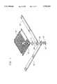
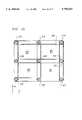
- FIG. 1is an exploded view showing the material elements of the present invention.
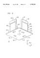
- FIG. 2is a perspective view of the bottom elements of the inventive pallet system.
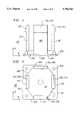
- FIG. 3is a side plan view in the yz plane of the bottom element shown in FIG. 2.
- FIG. 4is a top plan view thereof.
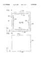
- FIG. 5is a perspective view of the top element of the pallet system.
- FIG. 6is a bottom plan view thereof.
- FIG. 7is a side plan view thereof.
- FIG. 8is perspective view of the box-like separation means of the present pallet system.
- FIG. 9is a top plan view thereof.
- FIG. 10is side plan view thereof.
- FIG. 11is vertical cross-sectional assembly view showing the mechanical coupling between the complemental engagement means of the bottom element, top element and inner walls of the z-axis separation means in the xz plane.
- FIG. 12is a view, similar to the view of FIG. 11, however, rotated ninety degrees about the z-axis therefrom.
- FIG. 13is a perspective view showing the top surfaces of the x and y axis linear offset members of the pallet system.
- FIG. 14is a bottom view of the linear offset member shown in FIG. 13.
- FIG. 15is a bottom plan view of the modular pallet system when assembled.
- FIG. 16is a perspective view of a quadrant of the honeycomb top layer of the present system.
- FIG. 17is a top plan view of the top layer quadrant of FIG. 16.
- FIG. 18is a side plan view thereof.
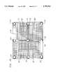
- FIG. 19is a top plan view of the assembled pallet system.
- FIG. 20is a perspective view of a tool used in the disassembly of the present system.
- FIG. 21is a perspective view showing insertion of the tool of FIG. 20 into a component defined by the combination by the bottom element, top element and box-like z-axis separation means.
- FIG. 1With reference to the exploded view of FIG. 1 there may, therein, be seen all of the material elements of the instant inventive modular pallet system.
- FIG. 1At the lower right of FIG. 1, there is shown an zyz axis Cartesian system to which reference is made below in referring to the orientation and position of the respective elements of the pallet system.
- FIG. 1shown a bottom element 10, a top element 12, a box-like z-axis separation means 14, a base layer defining x-axis linear offset member 16, a base layer defining y-axis linear offset member 18, and a quadrant of a top layer defining honeycomb structure 20.
- the bottom element 10may be more fully appreciated with reference to the perspective, side and top views of FIGS. 2, 3 and 4. There is, in said views, shown a rectilinear primary surface 20 having opposing x-axis edges 22 and y-axis edges 24. Said primary surface 20 is positionable in a first xy plane (see FIG. 1) which is a plane which defines the bottom layer of the present pallet system. In other words, as is more fully described below, said primary surface 20 of the bottom element 10 is substantially co-planer with the plane of the linear offset members 16 and 18 when said bottom element 10 has been fully inserted into openings 26 and 28 of the linear offset members 16 and 18 respectively.
- the bottom element 10may be seen to further include integrally dependent positive z-axis prongs 30, 32, 34 and 36, each of which originate at or near the x-axis edges 22 and y-axis edges 24 of the bottom element.
- each of said z-axis prongs 30 to 36terminates, at a positive z-axis end thereof, with first integral complemental engagement means 38, 39, 40 and 41 respectively.
- first integral complemental engagement means 38, 39, 40 and 41respectively.
- exterior engagement surfaces 42for each of said first engagement means 38 to 40. See FIGS. 3 and 4.
- the positive z-axis prongsare arranged within a substantially octagonal perimeter 48 for the purpose of which is to nest within the substantially octagonally geometry of said openings 28 and 26 in the x-axis linear members 26 and y-axis linear offset members 28.
- holes 50 and 52are also shown in the view of FIG. 4, the purpose of which is to facilitate disassembly of the present structure in the manner more fully set forth below.
- top element 56 of the modular pallet systemAs may be noted, top element 56 is similar as bottom element 10, however, inverted, and the prongs thereof are further from each other to permit coupling between top and bottom elements, as is more fully described below.
- the top element 56 of the inventive modular pallet systemincludes a rectilinear primary surface 58 having opposing x-axis edges 60 and y-axis edges 62. Said surface 58 is positionable in a second xy plane, above said first xy plane of said primary surface 20 of said bottom element 10.
- the top element 56exhibits integrally dependent negative z-axis prongs 130, 132, 134 and 136. Each of said prongs terminates, at negative z-axis ends thereof, with second integral complemental engagement means 138, 141, 139 and 140 respectively (see FIG. 6). It may, therefrom, be appreciated that each of the second complemental engagement means 138 to 141 exhibits inner inclined surfaces 144, 149, 145 and 146 respectively and exhibit outer inclined surfaces 142, 151, 143, and 147 respectively. The result of this geometry is the arrow-like prongs which appear in FIG. 5, as engagement means 138, 141, 139, and 140. The result of this structure is the arrow-like prong geometry at the end of prongs 130 and 134.
- said inner surfaces of said negative z-axis engagement means of element 56are proportioned for snap-fittable interlock with outer surfaces of the positive z-axis engagement means 30, 32, 34 and 36 of bottom element 10.
- FIG. 11shows the snap-fittable lock between outer surface 42 of said first complemental engagement means 38 of prong 30 of lower element 10 with surface 144 and second complemental engagement means 138 of prong 130 of top element 56.
- outer surface 42 of first complemental engagement means 40 of prong 34 of bottom element 10snap fittably interlocks with inner surface 145 of second complemental engagement means 139 of prong 134 of top element 56.
- each complemental engagement means of the bottom elementis locked, at an outer surface thereof, to an opposing inner surface of each complemental engagement means of the top element.
- the separation means 14more particularly, includes opposing xz axis walls 60 and opposing yz axis walls 62. Also, as may be noted, the separation means 14 is hollow throughout all interior xy planes 64/66 thereof. As may be noted in said view of FIG. 8, as well as in the top plan view of FIG. 9, the interior of the separation means 14 is provided with integrally-dependent means for snap-fittable interlock with outer surfaces of said second complemental engagement means of the prongs of the top element. More particularly, the interior of yz walls 62 are provided with integrally dependent means 68 for snap-fittable interlock, and the interior of xz plane walls 60 are provided with integrally dependent means 70 for snap-fittable interlock.
- interlock means 68 and 70to the complemental engagement means 138 to 141 of the prongs 130 to 136 of the top element may be more particularly seen with reference to the cross-sectional assembly views of FIGS. 11 and 12.
- the snap fittable interlock means 68 of wall 62 of separation means 14mates with outer surfaces 142 and 143 of second complemental engagement means 138 and 139 respectively.
- interlock means 70 of the xz axis walls of the separation means 14mate with outer surfaces 151 and 147 of second complemental engagement means 141 and 140 respectively of prongs 132 and 136 respectively of the top element 56. Accordingly, there is created a structure having rigid xy, xz, and yz surfaces.
- FIGS. 11 and 12the octagonal perimeter 48 of the prongs 30 thru 36 enable the nesting of bottom element 10 within said opening 26 and 28 of the respective x and y axis linear offset members 16 and 18 (see lower left of FIGS. 11 and 12).
- the appearance of the linear offset members 16 and 18may be more particularly seen with reference to the views of FIGS. 13 and 14 in which FIG. 13 is a top perspective view of a representative linear offset member and FIG. 14 is a bottom view thereof.
- the x and y linear offset membersdiffer only in the distance between the octagonal openings 26 and 28 therein.
- each of the separation meansis denoted by the designations S1 thru S9 in FIG. 15, as is the location of quadrants Q1 thru Q4 of the top layer defining honeycomb structure 21.
- Each of these quadrantsmay, more particularly, be seen in the views of FIGS. 16, 17 and 18.
- an octagonal opening of the type shown as opening 80may be used at each of the corners, that is, locations S1, S3, S7 and S9 of the present structure through simply rotating the structure of FIG. 16 and/or inverting the same.
- the z-axis separation means at the other locationnamely, S2, S4, S5, S6 and S8 may be accommodated through the one-half octagonal openings 82 which are shown in the structure of FIGS. 16 to 18.
- FIG. 19a top plan view of the entire inventive pallet system when assembled. As may be noted (see FIGS. 18 and 19) there is provided complemental interlock surfaces which enable male and female parts of lip means 84 to slide-fittably connect four of the structures 21 to each other to form the entire system shown in FIGS. 15 and 19.
- a disassembly tool 90including a handle 92, a central circular member 94 and lateral members 96, each having inclined surfaces 98. Said members 94 and each of members 96 are proportioned for insertion into openings 50/150 and 52/152 of the bottom and top elements respectively. The position of inclined surfaces 98 of the lateral members 96 is such that the application of a sufficient force or impact to surface 99 of handle 92 will cause the loosing of the above-described interlock of the complemental engagement means shown in FIGS. 11 and 12.
- each of the above set forth elements of the present inventionmay be molded and/or extruded using a high impact resistance thermoplastic polymer.
Landscapes
- Engineering & Computer Science (AREA)
- Mechanical Engineering (AREA)
- Pallets (AREA)
Abstract
Description
Claims (5)
Priority Applications (4)
| Application Number | Priority Date | Filing Date | Title |
|---|---|---|---|
| US08/562,507US5794543A (en) | 1995-09-05 | 1995-11-24 | Modular pallet system |
| US08/735,802US5791261A (en) | 1995-09-05 | 1996-10-21 | Modular pallet system |
| US08/795,856US5887529A (en) | 1995-09-05 | 1997-02-06 | Modular pallet with interlocking inserts |
| US08/796,571US5809905A (en) | 1995-09-05 | 1997-02-06 | Vertical interlocking modular pallet apparatus and method of construction |
Applications Claiming Priority (2)
| Application Number | Priority Date | Filing Date | Title |
|---|---|---|---|
| US52363995A | 1995-09-05 | 1995-09-05 | |
| US08/562,507US5794543A (en) | 1995-09-05 | 1995-11-24 | Modular pallet system |
Related Parent Applications (1)
| Application Number | Title | Priority Date | Filing Date |
|---|---|---|---|
| US52363995AContinuation-In-Part | 1995-09-05 | 1995-09-05 |
Related Child Applications (3)
| Application Number | Title | Priority Date | Filing Date |
|---|---|---|---|
| US08/735,802Continuation-In-PartUS5791261A (en) | 1995-09-05 | 1996-10-21 | Modular pallet system |
| US08/795,856Continuation-In-PartUS5887529A (en) | 1995-09-05 | 1997-02-06 | Modular pallet with interlocking inserts |
| US08/796,571Continuation-In-PartUS5809905A (en) | 1995-09-05 | 1997-02-06 | Vertical interlocking modular pallet apparatus and method of construction |
Publications (1)
| Publication Number | Publication Date |
|---|---|
| US5794543Atrue US5794543A (en) | 1998-08-18 |
Family
ID=24085814
Family Applications (1)
| Application Number | Title | Priority Date | Filing Date |
|---|---|---|---|
| US08/562,507Expired - Fee RelatedUS5794543A (en) | 1995-09-05 | 1995-11-24 | Modular pallet system |
Country Status (1)
| Country | Link |
|---|---|
| US (1) | US5794543A (en) |
Cited By (32)
| Publication number | Priority date | Publication date | Assignee | Title |
|---|---|---|---|---|
| US6234087B1 (en) | 2000-01-21 | 2001-05-22 | Alltrista Corporation | Machine dispensed modular pallet |
| EP1188678A1 (en)* | 2000-09-15 | 2002-03-20 | Bull S.A. | Transporting pallet and method of transporting loads |
| JP2003054556A (en)* | 2001-08-07 | 2003-02-26 | Ge Plastics Japan Ltd | Pallet made of thermoplastic resin |
| US20040025756A1 (en)* | 2002-07-18 | 2004-02-12 | Baker Gerald Lynn | Bulk bag with integral pallets |
| USD492835S1 (en) | 2002-12-23 | 2004-07-06 | Richard Stephen Michaels | Bulk bag |
| FR2859458A1 (en)* | 2003-09-04 | 2005-03-11 | Knauf Snc | Modular pallet for use with handling equipment, has pallet module formed by plate provided with bases, where plate has main base in shape of truncated pyramid with square section at level of corners and inner side completed by stoppers |
| US20050092638A1 (en)* | 2003-09-09 | 2005-05-05 | Richard Stephen Michaels | Pallet for bulk bag |
| US20060006675A1 (en)* | 2004-07-07 | 2006-01-12 | HENDRICKS Robert | Door jamb holding system |
| US20060032411A1 (en)* | 2004-08-12 | 2006-02-16 | 21St Century Plastics Corporation | Modular Pallet and Method |
| US20060075938A1 (en)* | 2004-10-12 | 2006-04-13 | Meissen Cynthia R | Connector for support structures |
| US20060144734A1 (en)* | 2002-10-23 | 2006-07-06 | Baker Gerald L | Bulk bag and rigid fork lift tine receiving member combination |
| US20060175218A1 (en)* | 2005-02-07 | 2006-08-10 | Mctavish Gordon | Bulk bag handling assembly |
| US20060278138A1 (en)* | 2005-06-14 | 2006-12-14 | Tung-Cheng Chi | Pallet |
| US20070237611A1 (en)* | 2006-04-11 | 2007-10-11 | Grams Merle A | Rack with forklift pocket |
| US20080271647A1 (en)* | 2007-05-02 | 2008-11-06 | Brett Boag | Pallet |
| US20090178595A1 (en)* | 2008-01-11 | 2009-07-16 | Shyong Tsuen Chen | Combination plastic pallet |
| US7779765B2 (en) | 2006-03-03 | 2010-08-24 | Daniel Kelly | Pallet with telescoped leg assemblies |
| WO2012012367A3 (en)* | 2010-07-19 | 2012-04-26 | Alx Pallet Systems, Llc | Metallic pallet with frame and panel support surface |
| USD659938S1 (en) | 2006-05-09 | 2012-05-15 | Lsi-Lift Systems Incorporated | Tubular pallet member |
| US9221580B2 (en) | 2013-06-10 | 2015-12-29 | Rehrig Pacific Company | Multiple pallet assembly |
| EP2996950A4 (en)* | 2013-05-13 | 2016-03-23 | Macro Plastics Inc | TRANSPORT CONTAINER AND ASSOCIATED SOIL CONNECTOR |
| JP2016074045A (en)* | 2014-10-02 | 2016-05-12 | 株式会社アイエイアイ | Actuator |
| US9527625B1 (en)* | 2015-10-02 | 2016-12-27 | Pallets.Com Llc | Pallet support block and a pallet constructed with pallet support blocks |
| US20170027411A1 (en)* | 2015-07-30 | 2017-02-02 | FRIES Planungs - und Marketinggesellschaft m.b.H. | Carrier arrangement for storing and/or transporting and/or cleaning dishware or other items |
| US9745097B2 (en) | 2015-10-02 | 2017-08-29 | Pallets.Com Llc | Pallet support block and a pallet constructed with pallet support blocks |
| WO2019101578A1 (en)* | 2017-11-21 | 2019-05-31 | I BOXIT Limited | Pallet |
| EP3621890A4 (en)* | 2017-04-24 | 2021-02-17 | Anders Nordell | Pallet |
| USD928445S1 (en) | 2020-04-06 | 2021-08-17 | Southwest Agri-Plastics, Inc. | Pallet rail |
| WO2021224732A1 (en) | 2020-05-07 | 2021-11-11 | Georg Utz Holding Ag | Plastic pallet with snap connection |
| USD942109S1 (en) | 2020-04-06 | 2022-01-25 | Southwest Agri-Plastics, Inc. | Pallet |
| US20240083650A1 (en)* | 2022-09-08 | 2024-03-14 | Plásticos Técnicos Mexicanos, S.A. De C.V. | Structural System For Load Stabilization Frame And Method For Assembling The Same |
| EP4545435A1 (en)* | 2023-10-24 | 2025-04-30 | Thomas Helpap | Modular load carrier, modular load carrier combination and modular load carrier system |
Citations (7)
| Publication number | Priority date | Publication date | Assignee | Title |
|---|---|---|---|---|
| US3857342A (en)* | 1973-06-27 | 1974-12-31 | Loechner J | Modular nestable pallet |
| FR2326607A1 (en)* | 1975-10-03 | 1977-04-29 | Burger Raymond | Wooden pallet mfg system - uses spiked function plates between wooden components which are pressed together |
| US4597338A (en)* | 1984-11-14 | 1986-07-01 | Pinckney Molded Plastics, Inc. | Pallet |
| US4604014A (en)* | 1984-07-12 | 1986-08-05 | Illinois Tool Works Inc. | Pallet fastener |
| US5197395A (en)* | 1988-08-09 | 1993-03-30 | Pigott Maurice J | Plastic pallet with deck assembly |
| US5388533A (en)* | 1988-08-09 | 1995-02-14 | Pigott; Brandon L. | Pallet and components thereof |
| US5483899A (en)* | 1994-07-05 | 1996-01-16 | Christie; Eugene P. | Modular pallet arrangement |
- 1995
- 1995-11-24USUS08/562,507patent/US5794543A/ennot_activeExpired - Fee Related
Patent Citations (7)
| Publication number | Priority date | Publication date | Assignee | Title |
|---|---|---|---|---|
| US3857342A (en)* | 1973-06-27 | 1974-12-31 | Loechner J | Modular nestable pallet |
| FR2326607A1 (en)* | 1975-10-03 | 1977-04-29 | Burger Raymond | Wooden pallet mfg system - uses spiked function plates between wooden components which are pressed together |
| US4604014A (en)* | 1984-07-12 | 1986-08-05 | Illinois Tool Works Inc. | Pallet fastener |
| US4597338A (en)* | 1984-11-14 | 1986-07-01 | Pinckney Molded Plastics, Inc. | Pallet |
| US5197395A (en)* | 1988-08-09 | 1993-03-30 | Pigott Maurice J | Plastic pallet with deck assembly |
| US5388533A (en)* | 1988-08-09 | 1995-02-14 | Pigott; Brandon L. | Pallet and components thereof |
| US5483899A (en)* | 1994-07-05 | 1996-01-16 | Christie; Eugene P. | Modular pallet arrangement |
Cited By (43)
| Publication number | Priority date | Publication date | Assignee | Title |
|---|---|---|---|---|
| US6234087B1 (en) | 2000-01-21 | 2001-05-22 | Alltrista Corporation | Machine dispensed modular pallet |
| EP1188678A1 (en)* | 2000-09-15 | 2002-03-20 | Bull S.A. | Transporting pallet and method of transporting loads |
| FR2814148A1 (en)* | 2000-09-15 | 2002-03-22 | Bull Sa | LOAD TRANSPORTATION METHOD AND RESULTING TRANSPORT PALLET |
| JP2003054556A (en)* | 2001-08-07 | 2003-02-26 | Ge Plastics Japan Ltd | Pallet made of thermoplastic resin |
| US7025208B2 (en) | 2002-07-18 | 2006-04-11 | Lsi-Lift Systems Incorporated | Bulk bag with integral pallets |
| US20040025756A1 (en)* | 2002-07-18 | 2004-02-12 | Baker Gerald Lynn | Bulk bag with integral pallets |
| US7594579B2 (en) | 2002-10-23 | 2009-09-29 | Gerald Lynn Baker | Bulk bag and rigid fork lift tine receiving member combination |
| US20060144734A1 (en)* | 2002-10-23 | 2006-07-06 | Baker Gerald L | Bulk bag and rigid fork lift tine receiving member combination |
| USD492835S1 (en) | 2002-12-23 | 2004-07-06 | Richard Stephen Michaels | Bulk bag |
| FR2859458A1 (en)* | 2003-09-04 | 2005-03-11 | Knauf Snc | Modular pallet for use with handling equipment, has pallet module formed by plate provided with bases, where plate has main base in shape of truncated pyramid with square section at level of corners and inner side completed by stoppers |
| US20050092638A1 (en)* | 2003-09-09 | 2005-05-05 | Richard Stephen Michaels | Pallet for bulk bag |
| US20060006675A1 (en)* | 2004-07-07 | 2006-01-12 | HENDRICKS Robert | Door jamb holding system |
| US20060032411A1 (en)* | 2004-08-12 | 2006-02-16 | 21St Century Plastics Corporation | Modular Pallet and Method |
| US7360493B2 (en) | 2004-08-12 | 2008-04-22 | 21St Century Plastics Corporation | Modular pallet and method |
| US7735429B2 (en)* | 2004-10-12 | 2010-06-15 | Rehrig Pacific Company | Connector for support structures |
| US20060075938A1 (en)* | 2004-10-12 | 2006-04-13 | Meissen Cynthia R | Connector for support structures |
| US8033726B2 (en) | 2005-02-07 | 2011-10-11 | LSI—Lift Systems Incorporated | Bulk bag handling assembly |
| US20060175218A1 (en)* | 2005-02-07 | 2006-08-10 | Mctavish Gordon | Bulk bag handling assembly |
| US20060278138A1 (en)* | 2005-06-14 | 2006-12-14 | Tung-Cheng Chi | Pallet |
| US7779765B2 (en) | 2006-03-03 | 2010-08-24 | Daniel Kelly | Pallet with telescoped leg assemblies |
| US20070237611A1 (en)* | 2006-04-11 | 2007-10-11 | Grams Merle A | Rack with forklift pocket |
| USD659938S1 (en) | 2006-05-09 | 2012-05-15 | Lsi-Lift Systems Incorporated | Tubular pallet member |
| US20080271647A1 (en)* | 2007-05-02 | 2008-11-06 | Brett Boag | Pallet |
| US20090178595A1 (en)* | 2008-01-11 | 2009-07-16 | Shyong Tsuen Chen | Combination plastic pallet |
| WO2012012367A3 (en)* | 2010-07-19 | 2012-04-26 | Alx Pallet Systems, Llc | Metallic pallet with frame and panel support surface |
| EP2996950A4 (en)* | 2013-05-13 | 2016-03-23 | Macro Plastics Inc | TRANSPORT CONTAINER AND ASSOCIATED SOIL CONNECTOR |
| US9221580B2 (en) | 2013-06-10 | 2015-12-29 | Rehrig Pacific Company | Multiple pallet assembly |
| JP2016074045A (en)* | 2014-10-02 | 2016-05-12 | 株式会社アイエイアイ | Actuator |
| US20170027411A1 (en)* | 2015-07-30 | 2017-02-02 | FRIES Planungs - und Marketinggesellschaft m.b.H. | Carrier arrangement for storing and/or transporting and/or cleaning dishware or other items |
| US10058230B2 (en)* | 2015-07-30 | 2018-08-28 | Fries Planungs- Und Marketinggesellschaft M.B.H. | Carrier arrangement for storing and/or transporting and/or cleaning dishware or other items |
| US9745097B2 (en) | 2015-10-02 | 2017-08-29 | Pallets.Com Llc | Pallet support block and a pallet constructed with pallet support blocks |
| US9527625B1 (en)* | 2015-10-02 | 2016-12-27 | Pallets.Com Llc | Pallet support block and a pallet constructed with pallet support blocks |
| EP3621890A4 (en)* | 2017-04-24 | 2021-02-17 | Anders Nordell | Pallet |
| WO2019101578A1 (en)* | 2017-11-21 | 2019-05-31 | I BOXIT Limited | Pallet |
| USD942109S1 (en) | 2020-04-06 | 2022-01-25 | Southwest Agri-Plastics, Inc. | Pallet |
| USD928445S1 (en) | 2020-04-06 | 2021-08-17 | Southwest Agri-Plastics, Inc. | Pallet rail |
| WO2021224732A1 (en) | 2020-05-07 | 2021-11-11 | Georg Utz Holding Ag | Plastic pallet with snap connection |
| CH717394A1 (en)* | 2020-05-07 | 2021-11-15 | Utz Georg Holding Ag | Plastic pallet with snap connection. |
| US20230166885A1 (en)* | 2020-05-07 | 2023-06-01 | Georg Utz Holding Ag | Plastic pallet with snap connection |
| US12037161B2 (en)* | 2020-05-07 | 2024-07-16 | Georg Utz Holding Ag | Plastic pallet with snap connection |
| US20240083650A1 (en)* | 2022-09-08 | 2024-03-14 | Plásticos Técnicos Mexicanos, S.A. De C.V. | Structural System For Load Stabilization Frame And Method For Assembling The Same |
| US12179981B2 (en)* | 2022-09-08 | 2024-12-31 | Plasticos Tecnicos Mexicanos, S.A. De C.V. | Structural system for load stabilization frame and method for assembling the same |
| EP4545435A1 (en)* | 2023-10-24 | 2025-04-30 | Thomas Helpap | Modular load carrier, modular load carrier combination and modular load carrier system |
Similar Documents
| Publication | Publication Date | Title |
|---|---|---|
| US5794543A (en) | Modular pallet system | |
| US5791261A (en) | Modular pallet system | |
| US5666886A (en) | Pallett assembly | |
| US5492069A (en) | Pallet assembly | |
| US3994241A (en) | Removable stacking frame assembly for pallets | |
| CA2537563C (en) | Article accommodating case | |
| US4597338A (en) | Pallet | |
| US5094175A (en) | Modular pallet arrangement | |
| US5456189A (en) | Shipping pallet | |
| US5497709A (en) | Plastic pallet assembly | |
| US5343814A (en) | Plastic pallet assembly | |
| US3572535A (en) | Collapsible storage container | |
| US20030136314A1 (en) | Pallet | |
| EP2528833A2 (en) | Pallets for the handling of goods, processes for manufacturing pallets and methods of using pallets in the handling of goods | |
| EP1009669A4 (en) | Modular pallet structure | |
| KR20080054385A (en) | Prefabricated box shape and plate connection structure | |
| US20060254476A1 (en) | Collapsible nestable pallet | |
| KR101852520B1 (en) | Prefabricated pallet equipped with a fixing pin | |
| US9527625B1 (en) | Pallet support block and a pallet constructed with pallet support blocks | |
| US11827413B2 (en) | Method of making packing boxes for shipping and storage | |
| KR20070111157A (en) | Prefabricated Plastic Pallets | |
| JP3397646B2 (en) | palette | |
| IT202000022018A1 (en) | PARTICULARLY VERSATILE PALLET | |
| KR101967237B1 (en) | Pallet | |
| JPH03289444A (en) | Synthetic resin pallet and its molding method |
Legal Events
| Date | Code | Title | Description |
|---|---|---|---|
| REMI | Maintenance fee reminder mailed | ||
| FPAY | Fee payment | Year of fee payment:4 | |
| SULP | Surcharge for late payment | ||
| AS | Assignment | Owner name:KRUGER, PAUL A., OKLAHOMA Free format text:ASSIGNMENT OF ASSIGNORS INTEREST;ASSIGNORS:PALWEB CORPORATION;PLASTIC PALLET PRODUCTION, INC.;REEL/FRAME:013735/0824 Effective date:20030110 | |
| AS | Assignment | Owner name:1607 COMMERCE LIMITED PARTNERSHIP, TEXAS Free format text:SECURITY AGREEMENT;ASSIGNORS:PALWEB CORPORATION, AN OKLAHOMA CORPORATION;PLASTIC PALLET PRODUCTION, INC., A TEXAS CORPORATION;REEL/FRAME:014196/0884 Effective date:20030908 | |
| AS | Assignment | Owner name:GREYSTONE LOGISTICS, INC., OKLAHOMA Free format text:MERGER;ASSIGNOR:PALWEB CORPORATION;REEL/FRAME:016745/0368 Effective date:20050318 | |
| REMI | Maintenance fee reminder mailed | ||
| LAPS | Lapse for failure to pay maintenance fees | ||
| STCH | Information on status: patent discontinuation | Free format text:PATENT EXPIRED DUE TO NONPAYMENT OF MAINTENANCE FEES UNDER 37 CFR 1.362 | |
| FP | Lapsed due to failure to pay maintenance fee | Effective date:20060818 | |
| AS | Assignment | Owner name:1607 COMMERCE LIMITED PARTNERSHIP, OKLAHOMA Free format text:ASSIGNMENT OF ASSIGNORS INTEREST;ASSIGNOR:GREYSTONE LOGISTICS, INC.;REEL/FRAME:019628/0533 Effective date:20070501 |