US5794016A - Parallel-processor graphics architecture - Google Patents
Parallel-processor graphics architectureDownload PDFInfo
- Publication number
- US5794016A US5794016AUS08/570,088US57008895AUS5794016AUS 5794016 AUS5794016 AUS 5794016AUS 57008895 AUS57008895 AUS 57008895AUS 5794016 AUS5794016 AUS 5794016A
- Authority
- US
- United States
- Prior art keywords
- memory
- rendering
- blocks
- processors
- graphics
- Prior art date
- Legal status (The legal status is an assumption and is not a legal conclusion. Google has not performed a legal analysis and makes no representation as to the accuracy of the status listed.)
- Expired - Lifetime
Links
Images


Classifications
- G—PHYSICS
- G06—COMPUTING OR CALCULATING; COUNTING
- G06F—ELECTRIC DIGITAL DATA PROCESSING
- G06F9/00—Arrangements for program control, e.g. control units
- G06F9/06—Arrangements for program control, e.g. control units using stored programs, i.e. using an internal store of processing equipment to receive or retain programs
- G06F9/46—Multiprogramming arrangements
- G06F9/50—Allocation of resources, e.g. of the central processing unit [CPU]
- G06F9/5005—Allocation of resources, e.g. of the central processing unit [CPU] to service a request
- G06F9/5011—Allocation of resources, e.g. of the central processing unit [CPU] to service a request the resources being hardware resources other than CPUs, Servers and Terminals
- G06F9/5016—Allocation of resources, e.g. of the central processing unit [CPU] to service a request the resources being hardware resources other than CPUs, Servers and Terminals the resource being the memory
- G—PHYSICS
- G06—COMPUTING OR CALCULATING; COUNTING
- G06T—IMAGE DATA PROCESSING OR GENERATION, IN GENERAL
- G06T1/00—General purpose image data processing
- G06T1/20—Processor architectures; Processor configuration, e.g. pipelining
Definitions
- the present inventionrelates to computer graphics and more particularly to a parallel-processor graphics architecture appropriate for multimedia graphics workstations that is scalable to the needs of a user.
- Structure traversalrefers to the traversal of an application's graphics data structure, either by the application or by a graphics library.
- Geometry processingrefers to floating point intensive operations, such as vertex transformation and shading, that convert the image data from an application's format into a geometric format of vertices comprising the image and vertex properties, such as color.
- renderingrefers to the process of calculating individual pixel values for the image that are stored in graphics memory based on the transformed geometric data.
- the processorswere assigned to large contiguous areas of memory. For instance, in a four processors system, the display screen would be divided into four large adjacent blocks with each processor assigned to a different block. The problem with this method is that it reduces the efficiency of the parallelism of the graphics system. If there were no objects for a processor to render in its area, then the processor sat idle and under utilized, while the other processors may have been overloaded. An extreme solution to this problem would be to assign one processor to one pixel, but as more and more processors are added, additional gains in performance decrease, while costs increase dramatically.
- Typical graphic systemsinclude a general-purpose base system with its own central processing unit and main memory, and special-purpose graphics hardware to accelerate the graphics applications. Since the introduction of the first special-purpose graphics hardware, physical memory restrictions have burdened low-level graphics software and firmware developers. To solve this problem, some graphics software interfaces provide a virtual memory abstraction to their applications to allow the application a view of an unlimited number of coexistent images it can create and maintain through the software interface.
- graphics virtual memory systemsinclude a simple memory-mapped frame-buffer method and a rendering processor method.
- the memory-mapped frame-buffer methodachieved virtual memory rendering by allowing the CPU to implement the rendering algorithms using a virtual memory system in the base system as the graphic memory system.
- the rendering processor methodalso used the main memory of the base system, but interfaced the main memory with a special-purpose rendering processor through a wide bus. While these systems have very different implementations, they are similar in their ability to render directly into processor virtual memory.
- the present inventionprovides a parallel graphics system and method for rendering an image on a display screen.
- the systemincludes a plurality of processors for rendering an image on the display screen, and a memory organized into noncontiguous groups of blocks.
- the system and methodfurther comprises block enable means for allocating at least one of the noncontiguous groups of blocks to each of the plurality of processors for rendering, thereby increasing the efficiency of the parallelism of the graphics system.
- the present inventionis scalable by the number of rendering processors utilized, and is configurable with respect to the allocation of the groups of the blocks to specific rendering processors.
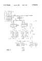
- FIG. 1depicts a low cost implementation of a graphics system having one rendering processor.
- FIG. 2is a block diagram depicting the graphics system with two rendering processors.
- FIG. 3depicts a high-end implementation of the graphics system with N rendering processors.
- FIG. 4is a block diagram depicting a graphics memory that has been divided into a plurality of blocks.
- FIGS. 5 and 6are block diagrams depicting the noncontiguous block organization of the present invention within a 4 ⁇ 4 array of adjacent blocks.
- FIG. 7is a block diagram of a rendering processor.
- FIG. 8is a block diagram showing three triangles, triangle A, triangle B, and triangle C that are to be rendered in blocks 0 and 1.
- FIG. 9is a block diagram showing a representative pixel and pixelmap within a graphics virtual memory 90.
- FIG. 10is a block diagram illustrating a rendering processor and an associated memory segment.
- FIG. 11is a functional block diagram of an address generation circuit.
- FIG. 12is a block diagram illustrating the contents of a TLB entry.
- the present inventionrelates to an improved parallel-processor graphics architecture.
- the following descriptionis presented to enable one of ordinary skill in the art to make and use the invention and is provided in the context of a patent application and its requirements.
- Various modifications to the preferred embodimentwill be readily apparent to those skilled in the art and the generic principles herein may be applied to other embodiments.
- the present inventionis not intended to be limited to the embodiment shown but is to be accorded the widest scope consistent with the principles and features described herein.
- FIGS. 1-3are block diagrams depicting a parallel-processor graphics system 10 of the present invention that is scalable to the needs of a user.
- the systemmay be configured with one rendering processor, or with multiple rendering processors.
- FIG. 1depicts a low-cost implementation of the graphics system 10A having one rendering processor 20A.
- FIG. 2is a block diagram depicting the graphics system 10B with two rendering processors 20A and 20B.
- FIG. 3depicts a high-end implementation of the graphics system 10C with N rendering processors 20A-20N.
- the efficiency of the multiple processorsis maximized by effectively distributing the rendering tasks, explained further below.
- the graphics system 10A, 10B, and 10C(hereinafter referred to as graphics system 10) is part of a general-purpose base computer system 12 including a CPU 14, a system chip set 16, and main memory 18.
- Each rendering processor 20A-20N(hereinafter referred to as rendering processor 20) in the graphics system 10 may be coupled to a graphics memory 22, a video digital-to-analog converter (VDAC) 24, a peripheral component interconnect (PCI) ROM 26, and a VGA processor 28.
- VDACvideo digital-to-analog converter
- PCIperipheral component interconnect
- the purpose of the rendering processor 20is to accept a geometric description of an object and scan-convert the object into the graphics memory 22.
- the graphics memory 22also known as a frame buffer, stores pixel data at memory addresses corresponding to pixels on a display device, such as a cathode ray tube (CRT) 29.
- the interconnect of the rendering processor 20comprises four major buses: a PCI bus 30, a memory bus 32, a video bus 34, and a utility bus (Ubus) 36.
- the PCI bus 30is a 32-bit bus that connects the rendering processor 20 to the general-purpose computer system 12.
- the rendering processors 20are connected to a system PCI bus 30A through a PCI bridge 38. Since only one load may be placed on the system PCI bus 30A, the PCI bridge 38 is used to translate the system PCI bus 30A into a second PCI bus 30B.
- the video bus 34provides pixel data from the rendering processors 20 to the VDAC 24 via a 64-bit interconnect
- the VDAC 24is a display interface that receives ordered pixel data from each of the rendering processors 20 in the form of digital color data, and passes the data to a CRT 29.
- the Ubus 36provides an input/output data path for the rendering processor's 20 ancillary chips, such as the VDAC 24, the VGA processor 28 and the PCI ROM 26.
- the VGA processor 28is provided so that the graphics system 10 is compatible with legacy systems.
- the rendering processor 20is the primary component of the graphics system 10 of the present invention.
- the rendering processor 20implements graphics and multimedia algorithms and interfaces with the PCI bus 30 and all other components in the system 10.
- the rendering processor 20integrates video technologies including 2D and 3D geometric graphics, photorealistic rendering, stereoscopic viewing, windowing operations, and live video.
- each rendering processor 20implements a set of parallel rendering algorithms including smooth shadowing, depth-buffering, dithering, antialiasing, transparency, blending, alpha testing, stenciling, stippling, accumulation buffering, and texture mapping.
- the rendering processor 20provides a video pipeline for multimedia applications through which live video data can be scaled, filtered, and converted into red, green, and blue color components for storage in graphics memory 22 and subsequent display.
- the graphics memory subsystem 22is partitioned into physical memory segments 42 and each memory segment 42 is coupled to a different rendering processor 20.
- Each rendering processor 20accesses only its memory segment 42 of the graphics memory 22 and is required to write only those pixels falling within that memory segment 42.
- rendering processor 20Bis coupled to memory segment 42B and writes only to those pixels contained within memory segment 42B of the graphics memory subsystem 22.
- the memory bus 32connects each rendering processor 20 to its corresponding graphics memory segment 42 via a 64-bit interconnect.
- the memory segments 42comprise synchronous dynamic random access memory (SDRAM).
- SDRAMsynchronous dynamic random access memory
- four 1M ⁇ 16 SDRAMsare used to construct an eight Mbyte graphics memory system 22.
- eight 1M ⁇ 16 SDRAMsare used to construct a sixteen Mbyte graphics memory system 22.
- sixteen 1M ⁇ 16 SDRAMsare used to construct a thirty-two Mbyte graphics memory system 22.
- the graphics memory 22could also be implemented using VRAM, in which case, the graphics memory 22 would connect directly to the VDAC 24.
- Prior methodshave divided graphics memory or display screen into partitions and allocated different parts of the memory or screen to separate processors. However, those methods are inefficient in the manner that the memory is allocated to the processors, which also creates dependencies among the processors.
- the present inventionprovides an improved method and system for allocating different parts of the graphics memory 22 to multiple rendering processors 20.
- the method and system for allocating the graphics memory 22increases the efficiency of the graphics system, and is configurable such that additional rendering processors 20 may be added to the graphic architecture, making the system scalable.
- FIG. 4depicting a block diagram of one embodiment of such a system.
- FIG. 4is a block diagram of a graphics memory 22 that has been partitioned into a plurality of pixel blocks 52 that are tiled in the x- and y-direction of the graphics memory 22.
- the graphics memory 22is large enough to render a 1280 ⁇ 1024 screen display.
- the pixel blocks 52are organized into noncontiguous groups of blocks 52, where blocks 52 in the same group are designated by the same number.
- the graphics memory 22 in FIG. 4is shown comprising sixteen groups of pixel blocks (0-15).
- the blocks 52 labeled "0"belong in group “0”
- the blocks labeled "1”belong in group “1”
- the blocks labeled "3”belong in group "3” et cetera.
- the groups of blocks 52 in the graphics memory 22are then assigned to the rendering processors 20 for rendering. Each rendering processor 20 writes to only those pixels that are located in the blocks 52 of the assigned groups.
- the groups of block 52may be assigned to the rendering processors 20 in varying ratios. Assuming there are sixteen rendering processors present in the multi-processor system 10C, then the sixteen groups of blocks 52 could be assigned to the processors 20 on a one-to-one basis. In this case, the blocks in group "0" may be assigned to rendering processor 0; the blocks in group "1" may be assigned to rendering processor 1; the blocks in group "2" may be assigned to rendering processor 2, and so on.
- FIGS. 5 and 6are block diagrams depicting the noncontiguous block organization of the present invention within one 4 ⁇ 4 array of adjacent blocks 52 in the graphics memory 22 (the 4 ⁇ 4 array is replicated throughout the graphics memory 22).
- the sixteen groups of pixel blocks 52 within each 4 ⁇ 4 arrayare tiled as in FIG. 4, where a particular group is designated by the middle number in the blocks 52, and the number in the upper right corner of the blocks 52 represents the processor to which a particular block is assigned.
- the groups of blocks 52may be assigned to the rendering processors 20 in higher ratios, such as two-to-one or four-to-one, rather than the one-to-one ratio above.
- processor 0is assigned to groups 0, 6, 11, and 13; processor 1 is assigned to groups 1, 7, 10, and 12; processor 2 is assigned to groups 2, 4, 9, and 15; and processor 3 is assigned to groups 3, 5, 8, and 14.
- FIG. 6what is shown is an example allocation of groups of blocks 52 when two rendering processors 20 (0-1) are present.
- the group of blocks 52are assigned to the rendering processors 20 in an eight-to-one ratio.
- processor 0is assigned to groups 0, 2, 5, 7, 8, 10, 13, and 15; and
- processor 1is assigned to groups 1, 3, 4, 6, 9, 11, 12, and 14.
- the assignment or mapping of various groups of blocks 52 to rendering processors 20is referred to as a processor map.
- the blocks 52 within a particular group that are assigned to a particular processor 20are arranged in a noncontiguous organization, and are spaced about the display. Therefore, the rendering demands placed on each of the rendering processors 20 should be equalized. That is, as the rendering processors 20 operate in parallel no rendering processor should be idle while others are overloaded. Therefore, the noncontiguous block organization of the present invention effectively increases the overall efficiency and performance of the graphics system 10.
- each pixel block 52is 128 ⁇ 128 pixels in size. This block size has been determined to effectively divide the parallelism of the rendering processors 20. Since polygons tend to be particularly small, and 128 ⁇ 128 blocks 52 are relatively large, polygons will not commonly cross block boundaries. The block size, however, is not so large as to slow the rendering processors 20 down when intensive rendering is required in a block 52. As stated above, when the blocks 52 are too large, the distribution of polygons becomes ineffective.
- Each rendering processor 20includes a configuration register 60, a command queue 62, a dispatcher circuit 64, a geometric setup circuit 66, an attribute setup circuit 70, an address generation circuit 68 and an interpolator circuit 72.
- the assignment of various blocks to particular rendering processorsis not fixed, but is rather alterable through programming.
- the block assignmentsare programmed through the configuration register 60, which sets the global state of the rendering processor 20.
- the configuration register 60includes a block enable field 61, an X-density field 74 and Y-density field 76.
- the block enable field 61determines which groups of blocks 52 within the graphics memory 22 are allocated to and controlled by the rendering processor 20. It is through the block enable field 61 that the parallelism among the rendering processors 20 may be configured.
- the block enable field 61includes a plurality of bits, where each bit corresponds to a particular group of blocks 52.
- a set bitimplies that a rendering processor 20 accesses the group of blocks 52 corresponding to that bit. For example, if bit zero is set within the block enable field 61 of a particular rendering processor 20, then that rendering processor 20 will access each block 52 in group "0".
- the bits in the block enable field 61must be mutually exclusive between rendering processors 20.
- the block enable field 61is sixteen-bits in length, implying there are sixteen group of blocks 52 that can be distributed among the processors 20. Rather than using a hardware register, the allocation of a group of blocks 52 to a particular processor 20 could also be implemented through software running on each of the rendering processors 20, or through a global register or software located remote from the rendering processors.
- the block enable field 61 for the rendering processor 0would contain the hexadecimal value "a5a5.” This means that bits 0, 2, 5, 7, 8, 10, 13 and 15 would be set to instruct the processor to render those groups of blocks 52.
- the block enable field 61 for rendering processor 1would contain the complementary hexadecimal value "5a5a.” This means that bits 1, 3, 4, 6, 9, 11, 12, and 14 would be set to instruct the processor to render those groups of blocks 52.
- the noncontiguous block organization shown in FIGS. 5-6distributes work among the rendering processors 20 in a more efficient manner than prior implementations, thereby improving parallelism.
- each rendering processor 20writes only those pixels that fall within the groups of blocks 52 to which it has been assigned.
- the pixels within the assigned groups of blocks 52are rendered in the memory segment 42 connected to that rendering processor 20.
- the use of memoryis conserved within the graphics system 10 through the X-density and Y-density fields 74 and 76 in the configuration register 60.
- the purpose of the X-density and Y-density fields 74 and 76is to instruct the rendering processor 20 how much of the memory segment 42 to reserve for pixels falling within the assigned groups of blocks 52. Stated another way, the X-density and Y-density fields 74 and 76 instruct the rendering processor 20 not to reserve physical memory for pixels falling within unassigned groups of blocks 52, thus saving memory in each of the memory segments 42.
- the blocks 52 within each row of blocks 52must be allocated to the same number of rendering processors 20, and similarly, the blocks 52 within each column of blocks 52 must be allocated to the same number of rendering processors 20. Furthermore, for ease of implementation, the number of processors 20 corresponding to the blocks 52 in each row of blocks 52 and to the blocks 52 in each column of blocks 52 must be a power of two. The following discussion assumes such an organization.
- the X-density and Y-density fields 74 and 76indicate the minimum size of a two-dimensional array of blocks 52 that, at any location within the graphics memory 22 aligned on a block boundary that is a multiple of the values of the X-density and Y-density 74 and 76 in the X and Y dimensions, respectively, include one and only one block allocated to each of the processors 20 in the system. If such a two-dimensional array is unachievable within the configuration's processor map, then the configuration can not achieve optimal memory usage within the scope of the present invention and the processor map should be altered accordingly. With an optimal processor map, the number of blocks 52 in the two-dimensional array determined by X-density and Y-density fields 74 and 76 should equal the number of processors 20 in the system.
- the X- and Y-density fields 74 and 76may be set to two and two, respectively, to four and one respectively, or to one and four, respectively; each of these settings will provide the same results.
- the X- and Y-density fields 74 and 76may be set to two and one respectively, or to one and two, respectively; each of these settings will provide the same results.
- the X- and Y-density fields 74 and 76instruct the rendering processors 20 not to reserve physical memory for pixels within unassigned blocks 52.
- a rendering processor 20uses its X-density and Y-density fields 74 and 76 to create ⁇ aliases ⁇ of pixel coordinate addresses to physical memory addresses. Specifically, all blocks 52 within a two-dimensional array of blocks 52 that is X-density by Y-density blocks 52 in size, and is aligned on a block boundary that is a multiple of X- and Y-density in the X and Y dimensions, respectively, share physical memory addresses.
- the 2 ⁇ 2 array formed from the groups of blocks 0, 1, 4, and 5will share physical memory addresses; the groups of blocks 2, 3, 6, and 7 will share physical memory addresses; the groups of blocks 8, 9, 12, and 13 will share physical memory addresses; and the groups of blocks 10, 11, 14, and 15 will share physical memory addresses.
- a rendering processor 20updates only the memory within the blocks 52 allocated to it by the block enable field, only the aliases corresponding to the allocated blocks 52 will be updated by the rendering processor 20.
- the aliases corresponding to groups 1, 4, and 5will not be updated by processor 0.
- the physical memory addresses shared by groups 0, 1, 4, and 5will contain only the data corresponding to the block in group 0.
- each rendering processor 20is reduced by a factor equivalent to the size of the two-dimensional array determined by X-density and Y-density fields 74 and 76, which is also equivalent to the number of rendering processors 20 in a configuration with an optimal processor map.
- the X- and Y-density fields 74 and 76can be implemented through software or through software or hardware located remote from the rendering processor.
- FIG. 8is a block diagram showing three triangles, triangle A, triangle B, and triangle C that are to be rendered in a block 52 belonging to group "0" and in a block 52 belonging to group "1".
- all objects appearing in the group "0" blocks (block 0)will be rendered by rendering processor 0, and all objects appearing in the group "1" blocks (block 1) will be rendered by rendering processor 1.
- the trianglesoriginate from a graphics application executing on the CPU 14, which performs all 3D pipeline calculations, such as transformations and shading computations.
- the CPU 14generates graphic command packets, which typically include 3D geometry information in the form of (x, y) coordinates and pixel intensity values (Red, Green, Blue) for the vertices comprising each triangle.
- the CPU 14is aware of the checkerboard pattern of the graphics memory 22, and from the triangle vertices determines in which blocks 52 the triangles will be visible or partially visible.
- the CPU 14sends command packets for triangle A to processor 0, and the command packets for triangle C to processor 1.
- each of the rendering processors 20independently scan-converts the geometric objects into the memory blocks 52 indicated by their block enable field 61.
- the rendering processor 20first reads the command packets sent to it over the PCI bus 30 and stores them in the command queue 62.
- the rendering processor 20then processes the command packets in a pipeline process comprising a dispatch stage 80, a setup stage 82, and an update stage 84.
- the dispatcher circuit 64reads the command packets from the command queue 62 and dispatches the vertex data in the command to the next stage in the pipeline, the setup stage 82.
- the setup stage 82includes the geometric setup circuit 66 and the attribute setup circuit 70, which operate in parallel. Both the geometric setup circuit 66 and the attribute setup circuit 70 accept the triangle vertex data in the form of (x, y) coordinate data, and setup the triangles for scan-conversion by the update stage 84.
- the geometric setup circuit 66determines initial geometry values in the form of (x, y) coordinates for the attribute setup circuit 70. Similarly, the attribute setup circuit 70 calculates initial attribute values for the interpolator circuit 72.
- the attributesinclude red, green, blue, z (depth), and transparency values.
- the update stage 84includes the address generation circuit 68 and the interpolator circuit 72, which also operate in parallel.
- the interpolator circuit 72uses the initial attribute values in order to interpolate final attribute values for the pixels in each triangle.
- the output of the interpolator circuit 72is used to update the pixel attributes in memory once the physical address for those pixels are calculated.
- the address generation circuit 68accepts the initial geometry values from the geometric setup circuit 66 and traverses each of the triangles in order to generate physical memory addresses for each of the pixels within each of the triangles.
- the graphics memory 22is a virtual memory system that remains relatively loosely integrated with the main memory 18 of the base system 12, and therefore enables system scalability.
- the graphics physical memory and virtual memory systemsare distinct from those of the base system 12. This allows a user to add graphic boards to the base system 12 that are equipped with a varying number of rendering processors 20.
- the present inventionallows the graphics subsystem 10 and base system 12 to evolve separately, and allows the graphics subsystem 10 to be portable to different base system architectures.
- graphic applicationsview the graphics memory system 22 as a virtual resource just as they view main memory 18 as a virtual resource.
- the CPU 14presents a higher-level abstraction of main memory 18 in terms of basic data structures, such as bytes and words
- the rendering processor 20presents a higher-level abstraction of the graphics memory 22 in terms of pixels and pixelmaps.
- a pixel 86is an N-bit unit of virtual memory 90, where N may represent 8 bits, 16 bits, or 32 bits.
- a pixelmap 88is a two-dimensional array of pixels 86, where an (x,y) coordinate pair references a pixel 86 within the pixelmap 88.
- a pixelmap's 88 coordinate spaceranges from -4096 to 4095 in both x and y, and a pixel 86 is 32 bits in length.
- a plurality of pixelmaps 88may exist in virtual memory 90, and some may be visible while others are not. Each pixelmap 88 is identified by a unique pixelmap ID, called a PID.
- FIG. 10is a block diagram illustrating a rendering processor 20 and an associated memory segment 42.
- the virtual memory 90 of the graphics system 10views a memory segment 42 as an array of page frames 92.
- the CPU 14manages the data movement, referred to as paging, between auxiliary storage devices and the memory segment 42. During the paging process when data is moved from auxiliary storage to a physical memory segment 42, enough data is transferred to completely fill a page frame 92.
- a page frame 92refers only to the memory itself, not the data stored in the page frame 92.
- the data stored in the memoryis a page.
- One page frame 92 of memorystores one page of data.
- a page frame 92is identified by a page frame number (PFN).
- a pageis identified by a virtual page number (VPN), typically the higher-order bits of the virtual address.
- PPNpage frame number
- VPNvirtual page number
- thirty-two page frames 92are used to map to one memory segment 42. All pages within the page frames 92 are the same size depending on the size of the memory segment 42. In a preferred embodiment, the page frames 92 are 64 KB when mapping to a 2 MB memory segment 42, 128 KB when mapping to a 4 MB memory segment 42, and 256 KB when mapping to an 8 MB memory segment 42.
- Visible pixelmaps 88have real-time requirements imposed by the CRT 29. The portions of those pixelmaps 88 with real-time requirements must always be resident within a memory segment 42 and therefore must occupy a fixed subset of the page frames 92. The number of page frames 92 occupied by the visible pixelmaps 88 depends on the display resolution and the number of rendering processors 20 sharing the visible pixelmaps 88.
- the geometric setup circuit 66passes the vertice coordinates of the triangles to the address generation circuit 68.
- the function of the address generation circuit 68is to traverses each triangle, generate virtual addresses for the pixels, and to then translate the virtual addresses into physical memory addresses within the corresponding memory segment 42.
- FIG. 11is a functional block diagram of the address generation circuit 68.
- the address generation circuit 68includes a virtual address generator circuit 94 and a translation lookaside buffer (TLB) 96.
- the virtual address generator circuit 94generates a virtual address 98 for each location within a geometric object, such as a triangle.
- a virtual address 98includes a pixelmap ID and an (x,y) coordinate pair.
- the TLB 96 in the address generation circuit 68is a hardware structure that provides a mapping of all page frames 92 resident in the memory segment 42. Given a virtual address 98 provided by the virtual address generator 94, the TLB 96 is used to determine the corresponding page frame number (PFN).
- PPNpage frame number
- a TLB 96 that provides a mapping of all page frames 92 resident in the memory segment 42is different from most TLB implementations, which map a relatively small number of page frames 92 and trap to system software when the TLB does not contain the desired mapping. According to the present invention, the rendering processor 20 will trap only when a referenced page is not resident in the memory segment 42. This is known as a page fault.
- each TLB 96contains thirty-two entries.
- FIG. 12is a block diagram illustrating the contents of a TLB entry 97.
- a TLB entry 97includes a VPN 100 and the PID 102 of the pixelmap ID.
- the VPN 100includes the high-order bits of the (x,y) coordinates.
- the TLB 96takes the PID and the high-order bits of the (x,y) coordinates in a virtual address 98 and compares them with all thirty-two entries 97 in the TLB 96.
- the TLB 96returns the corresponding page frame number (0-31). If the referenced VPN 100 is not resident in the memory segment 42 signaling a page fault, then the rendering processor 20 transmits an interrupt to the CPU 14. The CPU 14 responds by paging an old page out of the memory segment 42 and moving the requested data from base system 12 into the graphics memory 22 segment 42.
- the graphics virtual memory 90 systemis layered on top of the virtual memory of the base system 12, allowing the graphics system 10 to take advantage of existing mechanisms for backing up data to auxiliary storage.
- the address generation circuit 68determines the actual physical memory address 99 in the memory segment 42 for the (x,y) pixel coordinate.
- one goal of the address translation processis to avoid wasting memory in each memory segment 42.
- the rendering processor 20 assigned to block 0should not set aside physical memory for pixels 128 to 255 in block 1.
- the virtual memory for the pixelsshould not have a physical counterpart in the memory segment 42 of processor 0. Therefore, processor 0 will generate physical addresses for all the pixels in triangle B, but will only write to those pixels of triangle B that have physical addresses 99 in the memory segment 42 for processor 0.
- the block enable field 61 of the rendering processor 20is checked to determine if the generated physical address 99 is within the bounds of the corresponding memory segment 42. If it is, then the pixel attributes calculated by the interpolator circuit 72 are written into those physical addresses 99 in the memory segment 42; otherwise, the pixel attributes are not written.
- each virtual address generated by the address generator circuit 68results in the update of eight pixels at once.
- the update attributes for the eight pixelsare stored into a 4 ⁇ 2 array called an update array. Similar to how blocks are tiled in the graphics memory 22, the update arrays are tiled one after the other in each of the blocks 52.
- a parallel graphics method and systemhas been disclosed that is scalable by the number of rendering processors utilized, and is configurable with respect to the allocation of memory blocks to specific rendering processors.
Landscapes
- Engineering & Computer Science (AREA)
- Theoretical Computer Science (AREA)
- Software Systems (AREA)
- Physics & Mathematics (AREA)
- General Physics & Mathematics (AREA)
- General Engineering & Computer Science (AREA)
- Image Generation (AREA)
- Image Processing (AREA)
Abstract
Description
Claims (10)
Priority Applications (1)
| Application Number | Priority Date | Filing Date | Title |
|---|---|---|---|
| US08/570,088US5794016A (en) | 1995-12-11 | 1995-12-11 | Parallel-processor graphics architecture |
Applications Claiming Priority (1)
| Application Number | Priority Date | Filing Date | Title |
|---|---|---|---|
| US08/570,088US5794016A (en) | 1995-12-11 | 1995-12-11 | Parallel-processor graphics architecture |
Publications (1)
| Publication Number | Publication Date |
|---|---|
| US5794016Atrue US5794016A (en) | 1998-08-11 |
Family
ID=24278172
Family Applications (1)
| Application Number | Title | Priority Date | Filing Date |
|---|---|---|---|
| US08/570,088Expired - LifetimeUS5794016A (en) | 1995-12-11 | 1995-12-11 | Parallel-processor graphics architecture |
Country Status (1)
| Country | Link |
|---|---|
| US (1) | US5794016A (en) |
Cited By (108)
| Publication number | Priority date | Publication date | Assignee | Title |
|---|---|---|---|---|
| US5949439A (en)* | 1996-08-15 | 1999-09-07 | Chromatic Research, Inc. | Computing apparatus and operating method using software queues to improve graphics performance |
| US6122000A (en)* | 1997-06-03 | 2000-09-19 | Hewlett Packard Company | Synchronization of left/right channel display and vertical refresh in multi-display stereoscopic computer graphics systems |
| US6157395A (en)* | 1997-05-19 | 2000-12-05 | Hewlett-Packard Company | Synchronization of frame buffer swapping in multi-pipeline computer graphics display systems |
| US6184908B1 (en)* | 1998-04-27 | 2001-02-06 | Ati Technologies, Inc. | Method and apparatus for co-processing video graphics data |
| US6191793B1 (en) | 1998-04-01 | 2001-02-20 | Real 3D, Inc. | Method and apparatus for texture level of detail dithering |
| JP2001051668A (en)* | 1999-08-16 | 2001-02-23 | Sony Corp | Image processor |
| US20010051971A1 (en)* | 2000-03-16 | 2001-12-13 | Toshiaki Kato | Parallel object task engine and processing method |
| US6345350B2 (en)* | 1997-08-28 | 2002-02-05 | Seiko Epson Corporation | Information processing apparatus printer, method of controlling information processing apparatus and record medium |
| US20020015055A1 (en)* | 2000-07-18 | 2002-02-07 | Silicon Graphics, Inc. | Method and system for presenting three-dimensional computer graphics images using multiple graphics processing units |
| US6393543B1 (en)* | 1998-11-12 | 2002-05-21 | Acuid Corporation Limited | System and a method for transformation of memory device addresses |
| US20020109791A1 (en)* | 2001-02-15 | 2002-08-15 | Mark Champion | Two-dimensional buffer pages |
| US20020109694A1 (en)* | 2001-02-15 | 2002-08-15 | Mark Champion | Checkerboard buffer using two-dimensional buffer pages and using bit-field addressing |
| US20020109689A1 (en)* | 2001-02-15 | 2002-08-15 | Mark Champion | Checkerboard buffer using sequential memory locations |
| US20020110351A1 (en)* | 2001-02-15 | 2002-08-15 | Mark Champion | Checkerboard buffer |
| US20020110030A1 (en)* | 2001-02-15 | 2002-08-15 | Mark Champion | Swapped Pixel pages |
| US20020109699A1 (en)* | 2001-02-15 | 2002-08-15 | Mark Champion | Pixel pages optimized for GLV |
| US20020109792A1 (en)* | 2001-02-15 | 2002-08-15 | Mark Champion | Two-dimensional buffer pages using memory bank alternation |
| US20020109698A1 (en)* | 2001-02-15 | 2002-08-15 | Mark Champion | Checkerboard buffer using memory blocks |
| US20020109690A1 (en)* | 2001-02-15 | 2002-08-15 | Mark Champion | Checkerboard buffer using memory bank alternation |
| US20020109695A1 (en)* | 2001-02-15 | 2002-08-15 | Mark Champion | Checkerboard buffer using two-dimensional buffer pages and using state addressing |
| US20020109692A1 (en)* | 2001-02-15 | 2002-08-15 | Sony Corporation | Dynamic buffer pages |
| US20020109696A1 (en)* | 2001-02-15 | 2002-08-15 | Mark Champion | Checkerboard buffer using two-dimensional buffer pages and using memory bank alternation |
| US20020109693A1 (en)* | 2001-02-15 | 2002-08-15 | Mark Champion | Checkerboard buffer using two-dimensional buffer pages |
| US20020109691A1 (en)* | 2001-02-15 | 2002-08-15 | Mark Champion | Two-dimensional buffer pages using state addressing |
| US20020113904A1 (en)* | 2001-02-15 | 2002-08-22 | Mark Champion | Two-dimensional buffer pages using bit-field addressing |
| US20020130876A1 (en)* | 2001-02-15 | 2002-09-19 | Sony Corporation, A Japanese Corporation | Pixel pages using combined addressing |
| US6459429B1 (en) | 1999-06-14 | 2002-10-01 | Sun Microsystems, Inc. | Segmenting compressed graphics data for parallel decompression and rendering |
| US20020149596A1 (en)* | 2001-02-15 | 2002-10-17 | Mark Champion | Checkerboard buffer using more than two memory devices |
| US6476816B1 (en) | 1998-07-17 | 2002-11-05 | 3Dlabs Inc. Ltd. | Multi-processor graphics accelerator |
| US6529198B1 (en)* | 1999-03-16 | 2003-03-04 | Nec Corporation | Parallel rendering device |
| US20030058368A1 (en)* | 2001-09-24 | 2003-03-27 | Mark Champion | Image warping using pixel pages |
| US20030151609A1 (en)* | 2002-02-14 | 2003-08-14 | Mark Champion | Multi-sequence burst accessing for SDRAM |
| US20030160792A1 (en)* | 2002-02-27 | 2003-08-28 | Alcorn Byron A. | Distributed resource architecture and system |
| US20030160795A1 (en)* | 2002-02-27 | 2003-08-28 | Alcorn Byron A. | Centralized scalable resource architecture and system |
| US20030164832A1 (en)* | 2002-03-04 | 2003-09-04 | Alcorn Byron A. | Graphical display system and method |
| WO2003075253A1 (en) | 2002-03-01 | 2003-09-12 | Sony Computer Entertainment Inc. | Frame buffer access device, frame buffer access method, computer program and recording medium |
| US6631457B1 (en)* | 1999-11-01 | 2003-10-07 | Sony Computer Entertainment Inc. | Surface computer and computing method using the same |
| US20030222875A1 (en)* | 2002-03-01 | 2003-12-04 | Celsys Co., Ltd. | Method and program for generating a two-dimensional cartoonish picturization of a three-dimensional object |
| US6670958B1 (en)* | 2000-05-26 | 2003-12-30 | Ati International, Srl | Method and apparatus for routing data to multiple graphics devices |
| US6683614B2 (en) | 2001-12-21 | 2004-01-27 | Hewlett-Packard Development Company, L.P. | System and method for automatically configuring graphics pipelines by tracking a region of interest in a computer graphical display system |
| US20040100471A1 (en)* | 2002-11-27 | 2004-05-27 | Leather Mark M. | Dividing work among multiple graphics pipelines using a super-tiling technique |
| US20040100474A1 (en)* | 2002-11-27 | 2004-05-27 | Eric Demers | Apparatus for generating anti-aliased and stippled 3d lines, points and surfaces using multi-dimensional procedural texture coordinates |
| KR100436183B1 (en)* | 2002-10-09 | 2004-06-12 | 한국과학기술원 | Economical And Scalable Sort-Last System Using PC Cluster |
| US20040139427A1 (en)* | 2003-01-10 | 2004-07-15 | International Business Machines Corporation | Method and system for performing global processor resource assignment in an assembler |
| US20050065263A1 (en)* | 2003-09-22 | 2005-03-24 | Chung James Y.J. | Polycarbonate composition |
| US20050285864A1 (en)* | 2004-06-25 | 2005-12-29 | Diamond Michael B | Method and system for stand alone graphics independent of computer system form factor |
| US20050285865A1 (en)* | 2004-06-25 | 2005-12-29 | Diamond Michael B | Method and system for a scalable discrete graphics system |
| US7023413B1 (en)* | 1997-10-24 | 2006-04-04 | Canon Kabushiki Kaisha | Memory controller and liquid crystal display apparatus using the same |
| US20060164419A1 (en)* | 2005-01-24 | 2006-07-27 | Fujitsu Limited | Image drawing device and image drawing method |
| US20060170690A1 (en)* | 2002-11-18 | 2006-08-03 | Ati Technologies, Inc. | Method and apparatus for rasterizer interpolation |
| US20060267997A1 (en)* | 2005-05-24 | 2006-11-30 | Walls Jeffrey J | Systems and methods for rendering graphics in a multi-node rendering system |
| US20060271842A1 (en)* | 2005-05-27 | 2006-11-30 | Microsoft Corporation | Standard graphics specification and data binding |
| US20060274073A1 (en)* | 2004-11-17 | 2006-12-07 | Johnson Philip B | Multiple graphics adapter connection systems |
| US20060282781A1 (en)* | 2005-06-10 | 2006-12-14 | Diamond Michael B | Using a graphics system to enable a multi-user computer system |
| US20060279577A1 (en)* | 2004-01-28 | 2006-12-14 | Reuven Bakalash | Graphics processing and display system employing multiple graphics cores on a silicon chip of monolithic construction |
| US20070159488A1 (en)* | 2005-12-19 | 2007-07-12 | Nvidia Corporation | Parallel Array Architecture for a Graphics Processor |
| US20070268289A1 (en)* | 2006-05-16 | 2007-11-22 | Chun Yu | Graphics system with dynamic reposition of depth engine |
| US20070283356A1 (en)* | 2006-05-31 | 2007-12-06 | Yun Du | Multi-threaded processor with deferred thread output control |
| US20070279411A1 (en)* | 2003-11-19 | 2007-12-06 | Reuven Bakalash | Method and System for Multiple 3-D Graphic Pipeline Over a Pc Bus |
| US20070292047A1 (en)* | 2006-06-14 | 2007-12-20 | Guofang Jiao | Convolution filtering in a graphics processor |
| US20070296729A1 (en)* | 2006-06-21 | 2007-12-27 | Yun Du | Unified virtual addressed register file |
| US20080055328A1 (en)* | 2006-08-30 | 2008-03-06 | Jong-Chul Shin | Mapping method and video system for mapping pixel data included in the same pixel group to the same bank of memory |
| US20080084418A1 (en)* | 2003-11-19 | 2008-04-10 | Reuven Bakalash | Computing system capable of parallelizing the operation of multiple graphics processing units (GPUS) supported on an integrated graphics device (IGD) within a bridge circuit |
| US7372465B1 (en)* | 2004-12-17 | 2008-05-13 | Nvidia Corporation | Scalable graphics processing for remote display |
| US20080117217A1 (en)* | 2003-11-19 | 2008-05-22 | Reuven Bakalash | Multi-mode parallel graphics rendering system employing real-time automatic scene profiling and mode control |
| US20080158236A1 (en)* | 2006-12-31 | 2008-07-03 | Reuven Bakalash | Parallel graphics system employing multiple graphics pipelines wtih multiple graphics processing units (GPUs) and supporting the object division mode of parallel graphics rendering using pixel processing resources provided therewithin |
| US7477256B1 (en) | 2004-11-17 | 2009-01-13 | Nvidia Corporation | Connecting graphics adapters for scalable performance |
| US7576745B1 (en) | 2004-11-17 | 2009-08-18 | Nvidia Corporation | Connecting graphics adapters |
| JP2009535710A (en)* | 2006-04-26 | 2009-10-01 | クゥアルコム・インコーポレイテッド | Graphics system with configurable cache |
| US7598958B1 (en) | 2004-11-17 | 2009-10-06 | Nvidia Corporation | Multi-chip graphics processing unit apparatus, system, and method |
| US7602395B1 (en)* | 2005-04-22 | 2009-10-13 | Nvidia Corporation | Programming multiple chips from a command buffer for stereo image generation |
| US20090288096A1 (en)* | 2008-05-19 | 2009-11-19 | Ahmed Hazem Mohamed Rashid El-Mahdy | Load balancing for image processing using multiple processors |
| US20090303245A1 (en)* | 2008-04-30 | 2009-12-10 | Alexei Soupikov | Technique for performing load balancing for parallel rendering |
| US7633505B1 (en) | 2004-11-17 | 2009-12-15 | Nvidia Corporation | Apparatus, system, and method for joint processing in graphics processing units |
| US7633506B1 (en) | 2002-11-27 | 2009-12-15 | Ati Technologies Ulc | Parallel pipeline graphics system |
| US7663633B1 (en) | 2004-06-25 | 2010-02-16 | Nvidia Corporation | Multiple GPU graphics system for implementing cooperative graphics instruction execution |
| US7663621B1 (en)* | 2006-11-03 | 2010-02-16 | Nvidia Corporation | Cylindrical wrapping using shader hardware |
| US7721118B1 (en) | 2004-09-27 | 2010-05-18 | Nvidia Corporation | Optimizing power and performance for multi-processor graphics processing |
| US20100177108A1 (en)* | 2009-01-09 | 2010-07-15 | Seiko Epson Corporation | Image processing apparatus, image display apparatus and image processing method |
| US7768519B1 (en)* | 2006-09-19 | 2010-08-03 | Nvidia Corporation | High-performance crossbar for high throughput pipelines |
| US7796133B1 (en) | 2002-11-18 | 2010-09-14 | Ati Technologies Ulc | Unified shader |
| USRE41967E1 (en) | 2002-02-22 | 2010-11-30 | Takatoshi Ishii | Single-block virtual frame buffer translated to multiple physical blocks for multi-block display refresh generator |
| US20110057935A1 (en)* | 2009-09-10 | 2011-03-10 | Mark Fowler | Tiling Compaction in Multi-Processor Systems |
| US20110090220A1 (en)* | 2009-10-15 | 2011-04-21 | Molnar Steven E | Order-preserving distributed rasterizer |
| US7961194B2 (en) | 2003-11-19 | 2011-06-14 | Lucid Information Technology, Ltd. | Method of controlling in real time the switching of modes of parallel operation of a multi-mode parallel graphics processing subsystem embodied within a host computing system |
| US8134568B1 (en) | 2004-12-15 | 2012-03-13 | Nvidia Corporation | Frame buffer region redirection for multiple graphics adapters |
| US8212831B1 (en) | 2004-12-15 | 2012-07-03 | Nvidia Corporation | Broadcast aperture remapping for multiple graphics adapters |
| US8228328B1 (en)* | 2006-11-03 | 2012-07-24 | Nvidia Corporation | Early Z testing for multiple render targets |
| US8284207B2 (en) | 2003-11-19 | 2012-10-09 | Lucid Information Technology, Ltd. | Method of generating digital images of objects in 3D scenes while eliminating object overdrawing within the multiple graphics processing pipeline (GPPLS) of a parallel graphics processing system generating partial color-based complementary-type images along the viewing direction using black pixel rendering and subsequent recompositing operations |
| US20130076761A1 (en)* | 2011-09-22 | 2013-03-28 | Arm Limited | Graphics processing systems |
| US8446417B2 (en) | 2004-06-25 | 2013-05-21 | Nvidia Corporation | Discrete graphics system unit for housing a GPU |
| US20140177470A1 (en)* | 2012-12-20 | 2014-06-26 | Marvell World Trade Ltd. | Memory Sharing in a Network Device |
| US8884972B2 (en) | 2006-05-25 | 2014-11-11 | Qualcomm Incorporated | Graphics processor with arithmetic and elementary function units |
| US9087161B1 (en)* | 2004-06-28 | 2015-07-21 | Nvidia Corporation | Asymmetrical scaling multiple GPU graphics system for implementing cooperative graphics instruction execution |
| US20160224343A1 (en)* | 2013-09-18 | 2016-08-04 | Freescale Semiconductor, Inc. | Method and apparatus for performing register allocation |
| EP2984564A4 (en)* | 2013-04-11 | 2016-10-12 | Facebook Inc | PRE-GENERATION OF DISPLAY OBJECT |
| US9501847B1 (en)* | 2009-10-15 | 2016-11-22 | Nvidia Corporation | Parallel line stipple computation |
| US20170178386A1 (en)* | 2015-12-21 | 2017-06-22 | Imagination Technologies Limited | Allocation of Tiles to Processing Engines in a Graphics Processing System |
| US9704212B2 (en) | 2013-02-07 | 2017-07-11 | Nvidia Corporation | System and method for image processing |
| US9734546B2 (en) | 2013-10-03 | 2017-08-15 | Nvidia Corporation | Split driver to control multiple graphics processors in a computer system |
| US9760964B2 (en) | 2013-04-11 | 2017-09-12 | Facebook, Inc. | Application-tailored object re-use and recycling |
| US10026140B2 (en) | 2005-06-10 | 2018-07-17 | Nvidia Corporation | Using a scalable graphics system to enable a general-purpose multi-user computer system |
| US20180307621A1 (en)* | 2017-04-21 | 2018-10-25 | Intel Corporation | Memory access compression using clear code for tile pixels |
| US10126903B2 (en) | 2013-04-15 | 2018-11-13 | Facebook, Inc. | Application-tailored object pre-inflation |
| US20190035051A1 (en) | 2017-04-21 | 2019-01-31 | Intel Corporation | Handling pipeline submissions across many compute units |
| GB2611375A (en)* | 2022-03-30 | 2023-04-05 | Imagination Tech Ltd | Memory management for multicore 3-D graphics rendering |
| US12086654B2 (en) | 2021-09-16 | 2024-09-10 | T-Head (Shanghai) Semiconductor Co., Ltd. | Parallel processing unit virtualization |
| US12412234B2 (en) | 2022-03-30 | 2025-09-09 | Imagination Technologies Limited | Memory management for multicore 3-D graphics rendering |
Citations (11)
| Publication number | Priority date | Publication date | Assignee | Title |
|---|---|---|---|---|
| US4761736A (en)* | 1986-01-02 | 1988-08-02 | Commodore Business Machines, Inc. | Memory management unit for addressing an expanded memory in groups of non-contiguous blocks |
| US4949280A (en)* | 1988-05-10 | 1990-08-14 | Battelle Memorial Institute | Parallel processor-based raster graphics system architecture |
| US5117468A (en)* | 1989-03-03 | 1992-05-26 | Hitachi, Ltd. | Image processing system capable of carrying out local processing for image at high speed |
| US5276798A (en)* | 1990-09-14 | 1994-01-04 | Hughes Aircraft Company | Multifunction high performance graphics rendering processor |
| US5315699A (en)* | 1991-03-20 | 1994-05-24 | Research Development Corporation Of Japan | Filtering operation method for very high-speed image processing system |
| US5377320A (en)* | 1992-09-30 | 1994-12-27 | Sun Microsystems, Inc. | Method and apparatus for the rendering of trimmed nurb surfaces |
| US5388206A (en)* | 1992-11-13 | 1995-02-07 | The University Of North Carolina | Architecture and apparatus for image generation |
| US5392393A (en)* | 1993-06-04 | 1995-02-21 | Sun Microsystems, Inc. | Architecture for a high performance three dimensional graphics accelerator |
| US5408606A (en)* | 1993-01-07 | 1995-04-18 | Evans & Sutherland Computer Corp. | Computer graphics system with parallel processing using a switch structure |
| US5434967A (en)* | 1992-10-27 | 1995-07-18 | International Business Machines Corporation | Decision variable hardware logic and processing methods for graphics display system |
| US5493643A (en)* | 1994-05-03 | 1996-02-20 | Loral Aerospace Corp. | Image generator architecture employing tri-level fixed interleave processing and distribution buses |
- 1995
- 1995-12-11USUS08/570,088patent/US5794016A/ennot_activeExpired - Lifetime
Patent Citations (12)
| Publication number | Priority date | Publication date | Assignee | Title |
|---|---|---|---|---|
| US4761736A (en)* | 1986-01-02 | 1988-08-02 | Commodore Business Machines, Inc. | Memory management unit for addressing an expanded memory in groups of non-contiguous blocks |
| US4949280A (en)* | 1988-05-10 | 1990-08-14 | Battelle Memorial Institute | Parallel processor-based raster graphics system architecture |
| US5117468A (en)* | 1989-03-03 | 1992-05-26 | Hitachi, Ltd. | Image processing system capable of carrying out local processing for image at high speed |
| US5276798A (en)* | 1990-09-14 | 1994-01-04 | Hughes Aircraft Company | Multifunction high performance graphics rendering processor |
| US5315699A (en)* | 1991-03-20 | 1994-05-24 | Research Development Corporation Of Japan | Filtering operation method for very high-speed image processing system |
| US5377320A (en)* | 1992-09-30 | 1994-12-27 | Sun Microsystems, Inc. | Method and apparatus for the rendering of trimmed nurb surfaces |
| US5434967A (en)* | 1992-10-27 | 1995-07-18 | International Business Machines Corporation | Decision variable hardware logic and processing methods for graphics display system |
| US5388206A (en)* | 1992-11-13 | 1995-02-07 | The University Of North Carolina | Architecture and apparatus for image generation |
| US5408606A (en)* | 1993-01-07 | 1995-04-18 | Evans & Sutherland Computer Corp. | Computer graphics system with parallel processing using a switch structure |
| US5392393A (en)* | 1993-06-04 | 1995-02-21 | Sun Microsystems, Inc. | Architecture for a high performance three dimensional graphics accelerator |
| US5440682A (en)* | 1993-06-04 | 1995-08-08 | Sun Microsystems, Inc. | Draw processor for a high performance three dimensional graphic accelerator |
| US5493643A (en)* | 1994-05-03 | 1996-02-20 | Loral Aerospace Corp. | Image generator architecture employing tri-level fixed interleave processing and distribution buses |
Non-Patent Citations (4)
| Title |
|---|
| "High-Performance Polygon Rendering", Kurt Akeley, Tom Jermoluk, Silicon Graphics, Inc., pp. 6-12, (1988). |
| "Simulation and Expected Performance Analysis of Multiple Processor Z-Buffer Systems", Frederick I. Parke, Computer Graphics, vol. 14, No. 3, pp. 46-56 (Jul., 1980). |
| High Performance Polygon Rendering , Kurt Akeley, Tom Jermoluk, Silicon Graphics, Inc., pp. 6 12, (1988).* |
| Simulation and Expected Performance Analysis of Multiple Processor Z Buffer Systems , Frederick I. Parke, Computer Graphics, vol. 14, No. 3, pp. 46 56 (Jul., 1980).* |
Cited By (239)
| Publication number | Priority date | Publication date | Assignee | Title |
|---|---|---|---|---|
| US5949439A (en)* | 1996-08-15 | 1999-09-07 | Chromatic Research, Inc. | Computing apparatus and operating method using software queues to improve graphics performance |
| US6157395A (en)* | 1997-05-19 | 2000-12-05 | Hewlett-Packard Company | Synchronization of frame buffer swapping in multi-pipeline computer graphics display systems |
| US6122000A (en)* | 1997-06-03 | 2000-09-19 | Hewlett Packard Company | Synchronization of left/right channel display and vertical refresh in multi-display stereoscopic computer graphics systems |
| US6345350B2 (en)* | 1997-08-28 | 2002-02-05 | Seiko Epson Corporation | Information processing apparatus printer, method of controlling information processing apparatus and record medium |
| US7023413B1 (en)* | 1997-10-24 | 2006-04-04 | Canon Kabushiki Kaisha | Memory controller and liquid crystal display apparatus using the same |
| US6191793B1 (en) | 1998-04-01 | 2001-02-20 | Real 3D, Inc. | Method and apparatus for texture level of detail dithering |
| US6184908B1 (en)* | 1998-04-27 | 2001-02-06 | Ati Technologies, Inc. | Method and apparatus for co-processing video graphics data |
| US6476816B1 (en) | 1998-07-17 | 2002-11-05 | 3Dlabs Inc. Ltd. | Multi-processor graphics accelerator |
| US6393543B1 (en)* | 1998-11-12 | 2002-05-21 | Acuid Corporation Limited | System and a method for transformation of memory device addresses |
| US6529198B1 (en)* | 1999-03-16 | 2003-03-04 | Nec Corporation | Parallel rendering device |
| US6459429B1 (en) | 1999-06-14 | 2002-10-01 | Sun Microsystems, Inc. | Segmenting compressed graphics data for parallel decompression and rendering |
| JP2001051668A (en)* | 1999-08-16 | 2001-02-23 | Sony Corp | Image processor |
| US6727905B1 (en)* | 1999-08-16 | 2004-04-27 | Sony Corporation | Image data processing apparatus |
| US20040268080A1 (en)* | 1999-11-01 | 2004-12-30 | Sony Computer Entertainment Inc. | Surface computer and computing method using the same |
| US7035991B2 (en) | 1999-11-01 | 2006-04-25 | Sony Computer Entertainment Inc. | Surface computer and computing method using the same |
| US6631457B1 (en)* | 1999-11-01 | 2003-10-07 | Sony Computer Entertainment Inc. | Surface computer and computing method using the same |
| US7233331B2 (en) | 2000-03-16 | 2007-06-19 | Square Enix Co., Ltd. | Parallel object task engine and processing method |
| US20010051971A1 (en)* | 2000-03-16 | 2001-12-13 | Toshiaki Kato | Parallel object task engine and processing method |
| US6670958B1 (en)* | 2000-05-26 | 2003-12-30 | Ati International, Srl | Method and apparatus for routing data to multiple graphics devices |
| US20020130889A1 (en)* | 2000-07-18 | 2002-09-19 | David Blythe | System, method, and computer program product for real time transparency-based compositing |
| US7405734B2 (en)* | 2000-07-18 | 2008-07-29 | Silicon Graphics, Inc. | Method and system for presenting three-dimensional computer graphics images using multiple graphics processing units |
| US20020015055A1 (en)* | 2000-07-18 | 2002-02-07 | Silicon Graphics, Inc. | Method and system for presenting three-dimensional computer graphics images using multiple graphics processing units |
| US6765579B2 (en) | 2001-02-15 | 2004-07-20 | Sony Corporation | Pixel pages using combined addressing |
| US6831650B2 (en)* | 2001-02-15 | 2004-12-14 | Sony Corporation | Checkerboard buffer using sequential memory locations |
| US20020113904A1 (en)* | 2001-02-15 | 2002-08-22 | Mark Champion | Two-dimensional buffer pages using bit-field addressing |
| US20020130876A1 (en)* | 2001-02-15 | 2002-09-19 | Sony Corporation, A Japanese Corporation | Pixel pages using combined addressing |
| US20020109693A1 (en)* | 2001-02-15 | 2002-08-15 | Mark Champion | Checkerboard buffer using two-dimensional buffer pages |
| US20020109696A1 (en)* | 2001-02-15 | 2002-08-15 | Mark Champion | Checkerboard buffer using two-dimensional buffer pages and using memory bank alternation |
| US20020149596A1 (en)* | 2001-02-15 | 2002-10-17 | Mark Champion | Checkerboard buffer using more than two memory devices |
| US20020109692A1 (en)* | 2001-02-15 | 2002-08-15 | Sony Corporation | Dynamic buffer pages |
| US20020109695A1 (en)* | 2001-02-15 | 2002-08-15 | Mark Champion | Checkerboard buffer using two-dimensional buffer pages and using state addressing |
| US7379069B2 (en) | 2001-02-15 | 2008-05-27 | Sony Corporation | Checkerboard buffer using two-dimensional buffer pages |
| US20020109791A1 (en)* | 2001-02-15 | 2002-08-15 | Mark Champion | Two-dimensional buffer pages |
| US8547384B2 (en) | 2001-02-15 | 2013-10-01 | Sony Corporation | Checkerboard buffer |
| US7573483B2 (en) | 2001-02-15 | 2009-08-11 | Sony Corporation, A Japanese Corporation | Dynamic buffer pages |
| US20020109694A1 (en)* | 2001-02-15 | 2002-08-15 | Mark Champion | Checkerboard buffer using two-dimensional buffer pages and using bit-field addressing |
| US20020109689A1 (en)* | 2001-02-15 | 2002-08-15 | Mark Champion | Checkerboard buffer using sequential memory locations |
| US20020109690A1 (en)* | 2001-02-15 | 2002-08-15 | Mark Champion | Checkerboard buffer using memory bank alternation |
| US7205993B2 (en) | 2001-02-15 | 2007-04-17 | Sony Corporation | Checkerboard buffer using two-dimensional buffer pages and using memory bank alternation |
| US7830391B2 (en) | 2001-02-15 | 2010-11-09 | Sony Corporation | Checkerboard buffer using two-dimensional buffer pages |
| US20020109698A1 (en)* | 2001-02-15 | 2002-08-15 | Mark Champion | Checkerboard buffer using memory blocks |
| US7129953B2 (en) | 2001-02-15 | 2006-10-31 | Sony Corporation | Two dimensional buffer pages |
| US20020109792A1 (en)* | 2001-02-15 | 2002-08-15 | Mark Champion | Two-dimensional buffer pages using memory bank alternation |
| US7088369B2 (en) | 2001-02-15 | 2006-08-08 | Sony Corporation | Checkerboard buffer using two-dimensional buffer pages and using bit-field addressing |
| US7068281B2 (en) | 2001-02-15 | 2006-06-27 | Sony Corporation | Pixel pages optimized for GLV |
| US7046249B2 (en) | 2001-02-15 | 2006-05-16 | Sony Corporation | Swapped pixel pages |
| US7038691B2 (en) | 2001-02-15 | 2006-05-02 | Sony Corporation | Two-dimensional buffer pages using memory bank alternation |
| US6765580B2 (en) | 2001-02-15 | 2004-07-20 | Sony Corporation | Pixel pages optimized for GLV |
| US20080049032A1 (en)* | 2001-02-15 | 2008-02-28 | Sony Corporation | Checkerboard buffer using two-dimensional buffer pages |
| US6768490B2 (en) | 2001-02-15 | 2004-07-27 | Sony Corporation | Checkerboard buffer using more than two memory devices |
| US6791557B2 (en) | 2001-02-15 | 2004-09-14 | Sony Corporation | Two-dimensional buffer pages using bit-field addressing |
| US6795079B2 (en) | 2001-02-15 | 2004-09-21 | Sony Corporation | Two-dimensional buffer pages |
| US6801204B2 (en)* | 2001-02-15 | 2004-10-05 | Sony Corporation, A Japanese Corporation | Checkerboard buffer using memory blocks |
| US6803917B2 (en)* | 2001-02-15 | 2004-10-12 | Sony Corporation | Checkerboard buffer using memory bank alternation |
| US20040233206A1 (en)* | 2001-02-15 | 2004-11-25 | Sony Corporation, A Japanese Corporation | Pixel pages optimized for GLV |
| US6828977B2 (en) | 2001-02-15 | 2004-12-07 | Sony Corporation | Dynamic buffer pages |
| US20040246258A1 (en)* | 2001-02-15 | 2004-12-09 | Sony Corporation | Swapped pixel pages |
| US6831649B2 (en) | 2001-02-15 | 2004-12-14 | Sony Corporation | Two-dimensional buffer pages using state addressing |
| US6831651B2 (en)* | 2001-02-15 | 2004-12-14 | Sony Corporation | Checkerboard buffer |
| US20020109691A1 (en)* | 2001-02-15 | 2002-08-15 | Mark Champion | Two-dimensional buffer pages using state addressing |
| US20020109699A1 (en)* | 2001-02-15 | 2002-08-15 | Mark Champion | Pixel pages optimized for GLV |
| US6850241B2 (en) | 2001-02-15 | 2005-02-01 | Sony Corporation | Swapped pixel pages |
| US20050024368A1 (en)* | 2001-02-15 | 2005-02-03 | Xiping Liu | Two dimensional buffer pages |
| US20020110351A1 (en)* | 2001-02-15 | 2002-08-15 | Mark Champion | Checkerboard buffer |
| US20050057572A1 (en)* | 2001-02-15 | 2005-03-17 | Sony Corporation | Checkerboard buffer |
| US20020110030A1 (en)* | 2001-02-15 | 2002-08-15 | Mark Champion | Swapped Pixel pages |
| US20050104890A1 (en)* | 2001-02-15 | 2005-05-19 | Sony Corporation | Dynamic buffer pages |
| US6992674B2 (en) | 2001-02-15 | 2006-01-31 | Sony Corporation | Checkerboard buffer using two-dimensional buffer pages and using state addressing |
| US20030058368A1 (en)* | 2001-09-24 | 2003-03-27 | Mark Champion | Image warping using pixel pages |
| US6683614B2 (en) | 2001-12-21 | 2004-01-27 | Hewlett-Packard Development Company, L.P. | System and method for automatically configuring graphics pipelines by tracking a region of interest in a computer graphical display system |
| US20030151609A1 (en)* | 2002-02-14 | 2003-08-14 | Mark Champion | Multi-sequence burst accessing for SDRAM |
| US6965980B2 (en) | 2002-02-14 | 2005-11-15 | Sony Corporation | Multi-sequence burst accessing for SDRAM |
| USRE43235E1 (en) | 2002-02-22 | 2012-03-13 | Faust Communications, Llc | Single-block virtual frame buffer translated to multiple physical blocks for multi-block display refresh generator |
| USRE41967E1 (en) | 2002-02-22 | 2010-11-30 | Takatoshi Ishii | Single-block virtual frame buffer translated to multiple physical blocks for multi-block display refresh generator |
| US6909432B2 (en) | 2002-02-27 | 2005-06-21 | Hewlett-Packard Development Company, L.P. | Centralized scalable resource architecture and system |
| US6933943B2 (en) | 2002-02-27 | 2005-08-23 | Hewlett-Packard Development Company, L.P. | Distributed resource architecture and system |
| US20030160792A1 (en)* | 2002-02-27 | 2003-08-28 | Alcorn Byron A. | Distributed resource architecture and system |
| US20030160795A1 (en)* | 2002-02-27 | 2003-08-28 | Alcorn Byron A. | Centralized scalable resource architecture and system |
| US6992673B2 (en) | 2002-03-01 | 2006-01-31 | Sony Computer Entertainment, Inc. | Memory access device, semiconductor device, memory access method, computer program and recording medium |
| WO2003075253A1 (en) | 2002-03-01 | 2003-09-12 | Sony Computer Entertainment Inc. | Frame buffer access device, frame buffer access method, computer program and recording medium |
| US20030222875A1 (en)* | 2002-03-01 | 2003-12-04 | Celsys Co., Ltd. | Method and program for generating a two-dimensional cartoonish picturization of a three-dimensional object |
| US20030231176A1 (en)* | 2002-03-01 | 2003-12-18 | Masaaki Oka | Memory access device, semiconductor device, memory access method, computer program and recording medium |
| US6853380B2 (en)* | 2002-03-04 | 2005-02-08 | Hewlett-Packard Development Company, L.P. | Graphical display system and method |
| US20030164832A1 (en)* | 2002-03-04 | 2003-09-04 | Alcorn Byron A. | Graphical display system and method |
| KR100436183B1 (en)* | 2002-10-09 | 2004-06-12 | 한국과학기술원 | Economical And Scalable Sort-Last System Using PC Cluster |
| US20060170690A1 (en)* | 2002-11-18 | 2006-08-03 | Ati Technologies, Inc. | Method and apparatus for rasterizer interpolation |
| US7920141B2 (en) | 2002-11-18 | 2011-04-05 | Ati Technologies Ulc | Method and apparatus for rasterizer interpolation |
| US7796133B1 (en) | 2002-11-18 | 2010-09-14 | Ati Technologies Ulc | Unified shader |
| US8933945B2 (en)* | 2002-11-27 | 2015-01-13 | Ati Technologies Ulc | Dividing work among multiple graphics pipelines using a super-tiling technique |
| US7656416B2 (en)* | 2002-11-27 | 2010-02-02 | Ati Technologies, Inc. | Apparatus for generating anti-aliased and stippled 3d lines, points and surfaces using multi-dimensional procedural texture coordinates |
| US20040100474A1 (en)* | 2002-11-27 | 2004-05-27 | Eric Demers | Apparatus for generating anti-aliased and stippled 3d lines, points and surfaces using multi-dimensional procedural texture coordinates |
| US20040100471A1 (en)* | 2002-11-27 | 2004-05-27 | Leather Mark M. | Dividing work among multiple graphics pipelines using a super-tiling technique |
| US7633506B1 (en) | 2002-11-27 | 2009-12-15 | Ati Technologies Ulc | Parallel pipeline graphics system |
| US20100110084A1 (en)* | 2002-11-27 | 2010-05-06 | Ati Technologies Ulc | Parallel pipeline graphics system |
| US7111287B2 (en) | 2003-01-10 | 2006-09-19 | International Business Machines Corporation | Global processor resource assignment in an assembler |
| US20040139427A1 (en)* | 2003-01-10 | 2004-07-15 | International Business Machines Corporation | Method and system for performing global processor resource assignment in an assembler |
| US20050065263A1 (en)* | 2003-09-22 | 2005-03-24 | Chung James Y.J. | Polycarbonate composition |
| US20080117217A1 (en)* | 2003-11-19 | 2008-05-22 | Reuven Bakalash | Multi-mode parallel graphics rendering system employing real-time automatic scene profiling and mode control |
| US8125487B2 (en) | 2003-11-19 | 2012-02-28 | Lucid Information Technology, Ltd | Game console system capable of paralleling the operation of multiple graphic processing units (GPUS) employing a graphics hub device supported on a game console board |
| US20080084418A1 (en)* | 2003-11-19 | 2008-04-10 | Reuven Bakalash | Computing system capable of parallelizing the operation of multiple graphics processing units (GPUS) supported on an integrated graphics device (IGD) within a bridge circuit |
| US20080084419A1 (en)* | 2003-11-19 | 2008-04-10 | Reuven Bakalash | Computing system capable of parallelizing the operation of multiple graphics processing units supported on external graphics cards connected to a graphics hub device |
| US20080084422A1 (en)* | 2003-11-19 | 2008-04-10 | Reuven Bakalash | Computing system capable of parallelizing the operation of multiple graphics processing units (GPUS) supported on external graphics cards connected to a graphics hub device with image recomposition being carried out across two or more of said GPUS |
| US20080094402A1 (en)* | 2003-11-19 | 2008-04-24 | Reuven Bakalash | Computing system having a parallel graphics rendering system employing multiple graphics processing pipelines (GPPLS) dynamically controlled according to time, image and object division modes of parallel operation during the run-time of graphics-based applications running on the computing system |
| US7800619B2 (en) | 2003-11-19 | 2010-09-21 | Lucid Information Technology, Ltd. | Method of providing a PC-based computing system with parallel graphics processing capabilities |
| US7800610B2 (en) | 2003-11-19 | 2010-09-21 | Lucid Information Technology, Ltd. | PC-based computing system employing a multi-GPU graphics pipeline architecture supporting multiple modes of GPU parallelization dymamically controlled while running a graphics application |
| US20080117219A1 (en)* | 2003-11-19 | 2008-05-22 | Reuven Bakalash | PC-based computing system employing a silicon chip of monolithic construction having a routing unit, a control unit and a profiling unit for parallelizing the operation of multiple GPU-driven pipeline cores according to the object division mode of parallel operation |
| US7800611B2 (en) | 2003-11-19 | 2010-09-21 | Lucid Information Technology, Ltd. | Graphics hub subsystem for interfacing parallalized graphics processing units (GPUs) with the central processing unit (CPU) of a PC-based computing system having an CPU interface module and a PC bus |
| US7796130B2 (en) | 2003-11-19 | 2010-09-14 | Lucid Information Technology, Ltd. | PC-based computing system employing multiple graphics processing units (GPUS) interfaced with the central processing unit (CPU) using a PC bus and a hardware hub, and parallelized according to the object division mode of parallel operation |
| US7796129B2 (en) | 2003-11-19 | 2010-09-14 | Lucid Information Technology, Ltd. | Multi-GPU graphics processing subsystem for installation in a PC-based computing system having a central processing unit (CPU) and a PC bus |
| US8134563B2 (en) | 2003-11-19 | 2012-03-13 | Lucid Information Technology, Ltd | Computing system having multi-mode parallel graphics rendering subsystem (MMPGRS) employing real-time automatic scene profiling and mode control |
| US7812846B2 (en) | 2003-11-19 | 2010-10-12 | Lucid Information Technology, Ltd | PC-based computing system employing a silicon chip of monolithic construction having a routing unit, a control unit and a profiling unit for parallelizing the operation of multiple GPU-driven pipeline cores according to the object division mode of parallel operation |
| US20070279411A1 (en)* | 2003-11-19 | 2007-12-06 | Reuven Bakalash | Method and System for Multiple 3-D Graphic Pipeline Over a Pc Bus |
| US8085273B2 (en) | 2003-11-19 | 2011-12-27 | Lucid Information Technology, Ltd | Multi-mode parallel graphics rendering system employing real-time automatic scene profiling and mode control |
| US20080238917A1 (en)* | 2003-11-19 | 2008-10-02 | Lucid Information Technology, Ltd. | Graphics hub subsystem for interfacing parallalized graphics processing units (GPUS) with the central processing unit (CPU) of a PC-based computing system having an CPU interface module and a PC bus |
| US7961194B2 (en) | 2003-11-19 | 2011-06-14 | Lucid Information Technology, Ltd. | Method of controlling in real time the switching of modes of parallel operation of a multi-mode parallel graphics processing subsystem embodied within a host computing system |
| US7944450B2 (en) | 2003-11-19 | 2011-05-17 | Lucid Information Technology, Ltd. | Computing system having a hybrid CPU/GPU fusion-type graphics processing pipeline (GPPL) architecture |
| US7940274B2 (en) | 2003-11-19 | 2011-05-10 | Lucid Information Technology, Ltd | Computing system having a multiple graphics processing pipeline (GPPL) architecture supported on multiple external graphics cards connected to an integrated graphics device (IGD) embodied within a bridge circuit |
| US8754894B2 (en) | 2003-11-19 | 2014-06-17 | Lucidlogix Software Solutions, Ltd. | Internet-based graphics application profile management system for updating graphic application profiles stored within the multi-GPU graphics rendering subsystems of client machines running graphics-based applications |
| US8284207B2 (en) | 2003-11-19 | 2012-10-09 | Lucid Information Technology, Ltd. | Method of generating digital images of objects in 3D scenes while eliminating object overdrawing within the multiple graphics processing pipeline (GPPLS) of a parallel graphics processing system generating partial color-based complementary-type images along the viewing direction using black pixel rendering and subsequent recompositing operations |
| US7777748B2 (en) | 2003-11-19 | 2010-08-17 | Lucid Information Technology, Ltd. | PC-level computing system with a multi-mode parallel graphics rendering subsystem employing an automatic mode controller, responsive to performance data collected during the run-time of graphics applications |
| US7843457B2 (en) | 2003-11-19 | 2010-11-30 | Lucid Information Technology, Ltd. | PC-based computing systems employing a bridge chip having a routing unit for distributing geometrical data and graphics commands to parallelized GPU-driven pipeline cores supported on a plurality of graphics cards and said bridge chip during the running of a graphics application |
| US7808499B2 (en) | 2003-11-19 | 2010-10-05 | Lucid Information Technology, Ltd. | PC-based computing system employing parallelized graphics processing units (GPUS) interfaced with the central processing unit (CPU) using a PC bus and a hardware graphics hub having a router |
| US9584592B2 (en) | 2003-11-19 | 2017-02-28 | Lucidlogix Technologies Ltd. | Internet-based graphics application profile management system for updating graphic application profiles stored within the multi-GPU graphics rendering subsystems of client machines running graphics-based applications |
| US8754897B2 (en) | 2004-01-28 | 2014-06-17 | Lucidlogix Software Solutions, Ltd. | Silicon chip of a monolithic construction for use in implementing multiple graphic cores in a graphics processing and display subsystem |
| US7808504B2 (en) | 2004-01-28 | 2010-10-05 | Lucid Information Technology, Ltd. | PC-based computing system having an integrated graphics subsystem supporting parallel graphics processing operations across a plurality of different graphics processing units (GPUS) from the same or different vendors, in a manner transparent to graphics applications |
| US7834880B2 (en) | 2004-01-28 | 2010-11-16 | Lucid Information Technology, Ltd. | Graphics processing and display system employing multiple graphics cores on a silicon chip of monolithic construction |
| US9659340B2 (en) | 2004-01-28 | 2017-05-23 | Lucidlogix Technologies Ltd | Silicon chip of a monolithic construction for use in implementing multiple graphic cores in a graphics processing and display subsystem |
| US20080129745A1 (en)* | 2004-01-28 | 2008-06-05 | Lucid Information Technology, Ltd. | Graphics subsytem for integation in a PC-based computing system and providing multiple GPU-driven pipeline cores supporting multiple modes of parallelization dynamically controlled while running a graphics application |
| US7812844B2 (en) | 2004-01-28 | 2010-10-12 | Lucid Information Technology, Ltd. | PC-based computing system employing a silicon chip having a routing unit and a control unit for parallelizing multiple GPU-driven pipeline cores according to the object division mode of parallel operation during the running of a graphics application |
| US20080129744A1 (en)* | 2004-01-28 | 2008-06-05 | Lucid Information Technology, Ltd. | PC-based computing system employing a silicon chip implementing parallelized GPU-driven pipelines cores supporting multiple modes of parallelization dynamically controlled while running a graphics application |
| US20060279577A1 (en)* | 2004-01-28 | 2006-12-14 | Reuven Bakalash | Graphics processing and display system employing multiple graphics cores on a silicon chip of monolithic construction |
| US7812845B2 (en) | 2004-01-28 | 2010-10-12 | Lucid Information Technology, Ltd. | PC-based computing system employing a silicon chip implementing parallelized GPU-driven pipelines cores supporting multiple modes of parallelization dynamically controlled while running a graphics application |
| US8941668B2 (en) | 2004-06-25 | 2015-01-27 | Nvidia Corporation | Method and system for a scalable discrete graphics system |
| US20050285865A1 (en)* | 2004-06-25 | 2005-12-29 | Diamond Michael B | Method and system for a scalable discrete graphics system |
| US20050285864A1 (en)* | 2004-06-25 | 2005-12-29 | Diamond Michael B | Method and system for stand alone graphics independent of computer system form factor |
| US7663633B1 (en) | 2004-06-25 | 2010-02-16 | Nvidia Corporation | Multiple GPU graphics system for implementing cooperative graphics instruction execution |
| US8446417B2 (en) | 2004-06-25 | 2013-05-21 | Nvidia Corporation | Discrete graphics system unit for housing a GPU |
| US8411093B2 (en) | 2004-06-25 | 2013-04-02 | Nvidia Corporation | Method and system for stand alone graphics independent of computer system form factor |
| US9087161B1 (en)* | 2004-06-28 | 2015-07-21 | Nvidia Corporation | Asymmetrical scaling multiple GPU graphics system for implementing cooperative graphics instruction execution |
| US7721118B1 (en) | 2004-09-27 | 2010-05-18 | Nvidia Corporation | Optimizing power and performance for multi-processor graphics processing |
| US7576745B1 (en) | 2004-11-17 | 2009-08-18 | Nvidia Corporation | Connecting graphics adapters |
| US7598958B1 (en) | 2004-11-17 | 2009-10-06 | Nvidia Corporation | Multi-chip graphics processing unit apparatus, system, and method |
| US20060274073A1 (en)* | 2004-11-17 | 2006-12-07 | Johnson Philip B | Multiple graphics adapter connection systems |
| US7633505B1 (en) | 2004-11-17 | 2009-12-15 | Nvidia Corporation | Apparatus, system, and method for joint processing in graphics processing units |
| US8066515B2 (en) | 2004-11-17 | 2011-11-29 | Nvidia Corporation | Multiple graphics adapter connection systems |
| US7477256B1 (en) | 2004-11-17 | 2009-01-13 | Nvidia Corporation | Connecting graphics adapters for scalable performance |
| US8212831B1 (en) | 2004-12-15 | 2012-07-03 | Nvidia Corporation | Broadcast aperture remapping for multiple graphics adapters |
| US8134568B1 (en) | 2004-12-15 | 2012-03-13 | Nvidia Corporation | Frame buffer region redirection for multiple graphics adapters |
| US7372465B1 (en)* | 2004-12-17 | 2008-05-13 | Nvidia Corporation | Scalable graphics processing for remote display |
| CN100401319C (en)* | 2005-01-24 | 2008-07-09 | 富士通株式会社 | Image rendering device and image rendering method |
| US20060164419A1 (en)* | 2005-01-24 | 2006-07-27 | Fujitsu Limited | Image drawing device and image drawing method |
| US11341602B2 (en) | 2005-01-25 | 2022-05-24 | Google Llc | System on chip having processing and graphics units |
| US10867364B2 (en) | 2005-01-25 | 2020-12-15 | Google Llc | System on chip having processing and graphics units |
| US10614545B2 (en) | 2005-01-25 | 2020-04-07 | Google Llc | System on chip having processing and graphics units |
| US7602395B1 (en)* | 2005-04-22 | 2009-10-13 | Nvidia Corporation | Programming multiple chips from a command buffer for stereo image generation |
| US20060267997A1 (en)* | 2005-05-24 | 2006-11-30 | Walls Jeffrey J | Systems and methods for rendering graphics in a multi-node rendering system |
| US7444583B2 (en)* | 2005-05-27 | 2008-10-28 | Microsoft Corporation | Standard graphics specification and data binding |
| US20060271842A1 (en)* | 2005-05-27 | 2006-11-30 | Microsoft Corporation | Standard graphics specification and data binding |
| US8893016B2 (en) | 2005-06-10 | 2014-11-18 | Nvidia Corporation | Using a graphics system to enable a multi-user computer system |
| US20060282781A1 (en)* | 2005-06-10 | 2006-12-14 | Diamond Michael B | Using a graphics system to enable a multi-user computer system |
| US10026140B2 (en) | 2005-06-10 | 2018-07-17 | Nvidia Corporation | Using a scalable graphics system to enable a general-purpose multi-user computer system |
| JP2009520307A (en)* | 2005-12-19 | 2009-05-21 | エヌヴィディア コーポレイション | Graphics processor parallel array architecture |
| KR101027621B1 (en)* | 2005-12-19 | 2011-04-06 | 엔비디아 코포레이션 | Parallel Array Architecture for Graphics Processors |
| DE112006003473B4 (en)* | 2005-12-19 | 2011-07-14 | Nvidia Corp., Calif. | Parallel array architecture for a graphics processor |
| US7728841B1 (en)* | 2005-12-19 | 2010-06-01 | Nvidia Corporation | Coherent shader output for multiple targets |
| US8730249B2 (en)* | 2005-12-19 | 2014-05-20 | Nvidia Corporation | Parallel array architecture for a graphics processor |
| CN101371247B (en)* | 2005-12-19 | 2014-06-04 | 辉达公司 | Parallel array architecture for a graphics processor |
| GB2446546B (en)* | 2005-12-19 | 2011-05-04 | Nvidia Corp | Parallel array architecture for a graphics processor |
| WO2007111743A3 (en)* | 2005-12-19 | 2008-08-28 | Nvidia Corp | Parallel array architecture for a graphics processor |
| US20070159488A1 (en)* | 2005-12-19 | 2007-07-12 | Nvidia Corporation | Parallel Array Architecture for a Graphics Processor |
| JP2012178158A (en)* | 2005-12-19 | 2012-09-13 | Nvidia Corp | Parallel array architecture for graphics processor |
| US8766995B2 (en) | 2006-04-26 | 2014-07-01 | Qualcomm Incorporated | Graphics system with configurable caches |
| JP2009535710A (en)* | 2006-04-26 | 2009-10-01 | クゥアルコム・インコーポレイテッド | Graphics system with configurable cache |
| JP4938843B2 (en)* | 2006-04-26 | 2012-05-23 | クゥアルコム・インコーポレイテッド | Graphics system with configurable cache |
| US20070268289A1 (en)* | 2006-05-16 | 2007-11-22 | Chun Yu | Graphics system with dynamic reposition of depth engine |
| US8884972B2 (en) | 2006-05-25 | 2014-11-11 | Qualcomm Incorporated | Graphics processor with arithmetic and elementary function units |
| US20070283356A1 (en)* | 2006-05-31 | 2007-12-06 | Yun Du | Multi-threaded processor with deferred thread output control |
| US8869147B2 (en) | 2006-05-31 | 2014-10-21 | Qualcomm Incorporated | Multi-threaded processor with deferred thread output control |
| US8644643B2 (en) | 2006-06-14 | 2014-02-04 | Qualcomm Incorporated | Convolution filtering in a graphics processor |
| US20070292047A1 (en)* | 2006-06-14 | 2007-12-20 | Guofang Jiao | Convolution filtering in a graphics processor |
| US20070296729A1 (en)* | 2006-06-21 | 2007-12-27 | Yun Du | Unified virtual addressed register file |
| US8766996B2 (en) | 2006-06-21 | 2014-07-01 | Qualcomm Incorporated | Unified virtual addressed register file |
| US20080055328A1 (en)* | 2006-08-30 | 2008-03-06 | Jong-Chul Shin | Mapping method and video system for mapping pixel data included in the same pixel group to the same bank of memory |
| US8890881B2 (en)* | 2006-08-30 | 2014-11-18 | Samsung Electronics Co., Ltd. | Mapping method and video system for mapping pixel data included in the same pixel group to the same bank of memory |
| US7768519B1 (en)* | 2006-09-19 | 2010-08-03 | Nvidia Corporation | High-performance crossbar for high throughput pipelines |
| US8228328B1 (en)* | 2006-11-03 | 2012-07-24 | Nvidia Corporation | Early Z testing for multiple render targets |
| US7663621B1 (en)* | 2006-11-03 | 2010-02-16 | Nvidia Corporation | Cylindrical wrapping using shader hardware |
| US8243069B1 (en)* | 2006-11-03 | 2012-08-14 | Nvidia Corporation | Late Z testing for multiple render targets |
| US8232991B1 (en)* | 2006-11-03 | 2012-07-31 | Nvidia Corporation | Z-test result reconciliation with multiple partitions |
| US20080158236A1 (en)* | 2006-12-31 | 2008-07-03 | Reuven Bakalash | Parallel graphics system employing multiple graphics pipelines wtih multiple graphics processing units (GPUs) and supporting the object division mode of parallel graphics rendering using pixel processing resources provided therewithin |
| US8497865B2 (en) | 2006-12-31 | 2013-07-30 | Lucid Information Technology, Ltd. | Parallel graphics system employing multiple graphics processing pipelines with multiple graphics processing units (GPUS) and supporting an object division mode of parallel graphics processing using programmable pixel or vertex processing resources provided with the GPUS |
| US20090303245A1 (en)* | 2008-04-30 | 2009-12-10 | Alexei Soupikov | Technique for performing load balancing for parallel rendering |
| US8933943B2 (en)* | 2008-04-30 | 2015-01-13 | Intel Corporation | Technique for performing load balancing for parallel rendering |
| US8056086B2 (en)* | 2008-05-19 | 2011-11-08 | International Business Machines Corporation | Load balancing for image processing using multiple processors |
| US20090288096A1 (en)* | 2008-05-19 | 2009-11-19 | Ahmed Hazem Mohamed Rashid El-Mahdy | Load balancing for image processing using multiple processors |
| US8482570B2 (en)* | 2009-01-09 | 2013-07-09 | Seiko Epson Corporation | Parallel image processing apparatus and method with sampling pattern |
| US20100177108A1 (en)* | 2009-01-09 | 2010-07-15 | Seiko Epson Corporation | Image processing apparatus, image display apparatus and image processing method |
| US20110057935A1 (en)* | 2009-09-10 | 2011-03-10 | Mark Fowler | Tiling Compaction in Multi-Processor Systems |
| US8963931B2 (en)* | 2009-09-10 | 2015-02-24 | Advanced Micro Devices, Inc. | Tiling compaction in multi-processor systems |
| US9501847B1 (en)* | 2009-10-15 | 2016-11-22 | Nvidia Corporation | Parallel line stipple computation |
| US20110090220A1 (en)* | 2009-10-15 | 2011-04-21 | Molnar Steven E | Order-preserving distributed rasterizer |
| US8587581B2 (en) | 2009-10-15 | 2013-11-19 | Nvidia Corporation | Order-preserving distributed rasterizer |
| US8941653B2 (en) | 2009-10-15 | 2015-01-27 | Nvidia Corporation | Order-preserving distributed rasterizer |
| US9122646B2 (en)* | 2011-09-22 | 2015-09-01 | Arm Limited | Graphics processing systems |
| US20130076761A1 (en)* | 2011-09-22 | 2013-03-28 | Arm Limited | Graphics processing systems |
| US20140177470A1 (en)* | 2012-12-20 | 2014-06-26 | Marvell World Trade Ltd. | Memory Sharing in a Network Device |
| US9704212B2 (en) | 2013-02-07 | 2017-07-11 | Nvidia Corporation | System and method for image processing |
| US9760964B2 (en) | 2013-04-11 | 2017-09-12 | Facebook, Inc. | Application-tailored object re-use and recycling |
| US10896484B2 (en) | 2013-04-11 | 2021-01-19 | Facebook, Inc. | Method and system of display object pre-generation on windows of idle time available after each frame buffer fill tasks |
| US10354363B2 (en) | 2013-04-11 | 2019-07-16 | Facebook, Inc. | Displaying a pre-fetched object comprising a first associated with a desired content and a second element associated with time-sensitive information associated with the desired content |
| EP2984564A4 (en)* | 2013-04-11 | 2016-10-12 | Facebook Inc | PRE-GENERATION OF DISPLAY OBJECT |
| US10126903B2 (en) | 2013-04-15 | 2018-11-13 | Facebook, Inc. | Application-tailored object pre-inflation |
| US20160224343A1 (en)* | 2013-09-18 | 2016-08-04 | Freescale Semiconductor, Inc. | Method and apparatus for performing register allocation |
| US9841975B2 (en)* | 2013-09-18 | 2017-12-12 | Nxp Usa, Inc. | Method and apparatus for performing register allocation |
| US9734546B2 (en) | 2013-10-03 | 2017-08-15 | Nvidia Corporation | Split driver to control multiple graphics processors in a computer system |
| US20170178386A1 (en)* | 2015-12-21 | 2017-06-22 | Imagination Technologies Limited | Allocation of Tiles to Processing Engines in a Graphics Processing System |
| US10055877B2 (en)* | 2015-12-21 | 2018-08-21 | Imagination Technologies Limited | Allocation of tiles to processing engines in a graphics processing system |
| US10210651B2 (en) | 2015-12-21 | 2019-02-19 | Imagination Technologies Limited | Allocation of tiles to processing engines in a graphics processing system |
| US20190139294A1 (en)* | 2015-12-21 | 2019-05-09 | Imagination Technologies Limited | Allocation of tiles to processing engines in a graphics processing system |
| US10475228B2 (en) | 2015-12-21 | 2019-11-12 | Imagination Technologies Limited | Allocation of tiles to processing engines in a graphics processing system |
| US10268596B2 (en)* | 2017-04-21 | 2019-04-23 | Intel Corporation | Memory access compression using clear code for tile pixels |
| US20180307621A1 (en)* | 2017-04-21 | 2018-10-25 | Intel Corporation | Memory access compression using clear code for tile pixels |
| US10621109B2 (en)* | 2017-04-21 | 2020-04-14 | Intel Corporation | Memory access compression using clear code for tile pixels |
| US20190236026A1 (en)* | 2017-04-21 | 2019-08-01 | Intel Corporation | Memory access compression using clear code for tile pixels |
| US20190035051A1 (en) | 2017-04-21 | 2019-01-31 | Intel Corporation | Handling pipeline submissions across many compute units |
| US10896479B2 (en) | 2017-04-21 | 2021-01-19 | Intel Corporation | Handling pipeline submissions across many compute units |
| US10977762B2 (en) | 2017-04-21 | 2021-04-13 | Intel Corporation | Handling pipeline submissions across many compute units |
| US11061823B2 (en) | 2017-04-21 | 2021-07-13 | Intel Corporation | Memory access compression using clear code for tile pixels |
| US11244420B2 (en) | 2017-04-21 | 2022-02-08 | Intel Corporation | Handling pipeline submissions across many compute units |
| US10497087B2 (en) | 2017-04-21 | 2019-12-03 | Intel Corporation | Handling pipeline submissions across many compute units |
| US11620723B2 (en) | 2017-04-21 | 2023-04-04 | Intel Corporation | Handling pipeline submissions across many compute units |
| US12073489B2 (en) | 2017-04-21 | 2024-08-27 | Intel Corporation | Handling pipeline submissions across many compute units |
| US11675711B2 (en) | 2017-04-21 | 2023-06-13 | Intel Corporation | Memory access compression using clear code for tile pixels |
| US11803934B2 (en) | 2017-04-21 | 2023-10-31 | Intel Corporation | Handling pipeline submissions across many compute units |
| US12001344B2 (en) | 2017-04-21 | 2024-06-04 | Intel Corporation | Memory access compression using clear code for tile pixels |
| US12086654B2 (en) | 2021-09-16 | 2024-09-10 | T-Head (Shanghai) Semiconductor Co., Ltd. | Parallel processing unit virtualization |
| GB2611375A (en)* | 2022-03-30 | 2023-04-05 | Imagination Tech Ltd | Memory management for multicore 3-D graphics rendering |
| GB2611375B (en)* | 2022-03-30 | 2025-03-26 | Imagination Tech Ltd | Memory management for multicore 3-D graphics rendering |
| US12412234B2 (en) | 2022-03-30 | 2025-09-09 | Imagination Technologies Limited | Memory management for multicore 3-D graphics rendering |
Similar Documents
| Publication | Publication Date | Title |
|---|---|---|
| US5794016A (en) | Parallel-processor graphics architecture | |
| US7289125B2 (en) | Graphics device clustering with PCI-express | |
| US6906720B2 (en) | Multipurpose memory system for use in a graphics system | |
| US7015915B1 (en) | Programming multiple chips from a command buffer | |
| JP3350043B2 (en) | Graphic processing apparatus and graphic processing method | |
| US6911983B2 (en) | Double-buffering of pixel data using copy-on-write semantics | |
| US5990912A (en) | Virtual address access to tiled surfaces | |
| US8766996B2 (en) | Unified virtual addressed register file | |
| Potmesil et al. | The pixel machine: a parallel image computer | |
| Montrym et al. | InfiniteReality: A real-time graphics system | |
| US5969726A (en) | Caching and coherency control of multiple geometry accelerators in a computer graphics system | |
| JP3026788B2 (en) | Computer system with unified memory architecture | |
| JP2683564B2 (en) | Software-configurable memory structure for data processing system with graphic processing function | |
| US7333115B2 (en) | Image processing apparatus and method thereof | |
| US6940514B1 (en) | Parallel initialization path for rasterization engine | |
| US8018467B2 (en) | Texture caching arrangement for a computer graphics accelerator | |
| JP2673101B2 (en) | Computer graphics equipment | |
| US20110057935A1 (en) | Tiling Compaction in Multi-Processor Systems | |
| JPH10177659A (en) | Three-dimensional graphic accelerator for executing multilogic bus while using improved common data line for bus communication | |
| JPH10116355A (en) | Three-dimensional graphics accelerator provided with direct data channel for improving performance | |
| US6795078B2 (en) | Parallel read with source-clear operation | |
| KR20130132752A (en) | Displaying compressed supertile images | |
| US6943804B2 (en) | System and method for performing BLTs | |
| US6982719B2 (en) | Switching sample buffer context in response to sample requests for real-time sample filtering and video generation | |
| JP3397709B2 (en) | Frame buffer linear addressing method |
Legal Events
| Date | Code | Title | Description |
|---|---|---|---|
| AS | Assignment | Owner name:COMERICA BANK - CALIFORNIA, CALIFORNIA Free format text:SECURITY AGREEMENT;ASSIGNOR:DYNAMIC PICTURES, INC.;REEL/FRAME:008199/0321 Effective date:19960827 | |
| AS | Assignment | Owner name:SILICON VALLEY BANK, CALIFORNIA Free format text:SECURITY INTEREST;ASSIGNOR:DYNAMIC PICTURES INCORPORATED;REEL/FRAME:008865/0102 Effective date:19971126 | |
| STCF | Information on status: patent grant | Free format text:PATENTED CASE | |
| AS | Assignment | Owner name:DYNAMIC PICTURES INCORPORATED, CALIFORNIA Free format text:RELEASE BY SECURED PARTY;ASSIGNOR:SILICON VALLEY BANK;REEL/FRAME:010615/0758 Effective date:20000201 | |
| AS | Assignment | Owner name:FOOTHILL CAPITAL CORPORATION, CALIFORNIA Free format text:SECURITY AGREEMENT;ASSIGNORS:3DLABS INC., LTD., AND CERTAIN OF PARENT'S SUBSIDIARIES;3DLABS INC., LTD.;3DLABS (ALABAMA) INC.;AND OTHERS;REEL/FRAME:012043/0880 Effective date:20010727 | |
| FPAY | Fee payment | Year of fee payment:4 | |
| AS | Assignment | Owner name:3DLABS (ALABAMA) INC., ALABAMA Free format text:RELEASE OF SECURITY AGREEMENT;ASSIGNOR:WELL FARGO FOOTHILL, INC., FORMERLY KNOWN AS FOOTHILL CAPITAL CORPORATION;REEL/FRAME:015722/0752 Effective date:20030909 Owner name:3DLABS INC., A CORP. OF DE, CALIFORNIA Free format text:RELEASE OF SECURITY AGREEMENT;ASSIGNOR:WELL FARGO FOOTHILL, INC., FORMERLY KNOWN AS FOOTHILL CAPITAL CORPORATION;REEL/FRAME:015722/0752 Effective date:20030909 Owner name:3DLABS INC., A COMPANY ORGANIZED UNDER THE LAWS OF Free format text:RELEASE OF SECURITY AGREEMENT;ASSIGNOR:WELL FARGO FOOTHILL, INC., FORMERLY KNOWN AS FOOTHILL CAPITAL CORPORATION;REEL/FRAME:015722/0752 Effective date:20030909 Owner name:3DLABS LIMITED, A COMPANY ORGANIZED UNDER THE LAWS Free format text:RELEASE OF SECURITY AGREEMENT;ASSIGNOR:WELL FARGO FOOTHILL, INC., FORMERLY KNOWN AS FOOTHILL CAPITAL CORPORATION;REEL/FRAME:015722/0752 Effective date:20030909 Owner name:3DLABS (ALABAMA) INC.,ALABAMA Free format text:RELEASE OF SECURITY AGREEMENT;ASSIGNOR:WELL FARGO FOOTHILL, INC., FORMERLY KNOWN AS FOOTHILL CAPITAL CORPORATION;REEL/FRAME:015722/0752 Effective date:20030909 Owner name:3DLABS INC., A CORP. OF DE,CALIFORNIA Free format text:RELEASE OF SECURITY AGREEMENT;ASSIGNOR:WELL FARGO FOOTHILL, INC., FORMERLY KNOWN AS FOOTHILL CAPITAL CORPORATION;REEL/FRAME:015722/0752 Effective date:20030909 Owner name:3DLABS INC., LTD., A COMPANY ORGANIZED UNDER THE L Free format text:RELEASE OF SECURITY AGREEMENT;ASSIGNOR:WELL FARGO FOOTHILL, INC., FORMERLY KNOWN AS FOOTHILL CAPITAL CORPORATION;REEL/FRAME:015722/0752 Effective date:20030909 | |
| FEPP | Fee payment procedure | Free format text:PAT HOLDER NO LONGER CLAIMS SMALL ENTITY STATUS, ENTITY STATUS SET TO UNDISCOUNTED (ORIGINAL EVENT CODE: STOL); ENTITY STATUS OF PATENT OWNER: LARGE ENTITY | |
| REFU | Refund | Free format text:REFUND - PAYMENT OF MAINTENANCE FEE, 8TH YR, SMALL ENTITY (ORIGINAL EVENT CODE: R2552); ENTITY STATUS OF PATENT OWNER: LARGE ENTITY | |
| FPAY | Fee payment | Year of fee payment:8 | |
| FEPP | Fee payment procedure | Free format text:ENTITY STATUS SET TO UNDISCOUNTED (ORIGINAL EVENT CODE: BIG.); ENTITY STATUS OF PATENT OWNER: LARGE ENTITY | |
| AS | Assignment | Owner name:3DLABS INC. LTD., BERMUDA Free format text:MERGER;ASSIGNOR:DYNAMIC PICTURES INCORPORATED;REEL/FRAME:017448/0038 Effective date:19990614 | |
| FPAY | Fee payment | Year of fee payment:12 | |
| AS | Assignment | Owner name:ZIILABS INC., LTD., BERMUDA Free format text:CHANGE OF NAME;ASSIGNOR:3DLABS INC., LTD.;REEL/FRAME:032588/0125 Effective date:20110106 |