US5793905A - Method and device for switching of optical radiations of orthogonal polarizations - Google Patents
Method and device for switching of optical radiations of orthogonal polarizationsDownload PDFInfo
- Publication number
- US5793905A US5793905AUS08/776,204US77620497AUS5793905AUS 5793905 AUS5793905 AUS 5793905AUS 77620497 AUS77620497 AUS 77620497AUS 5793905 AUS5793905 AUS 5793905A
- Authority
- US
- United States
- Prior art keywords
- optical
- pumping
- switching
- signal
- birefringent
- Prior art date
- Legal status (The legal status is an assumption and is not a legal conclusion. Google has not performed a legal analysis and makes no representation as to the accuracy of the status listed.)
- Expired - Fee Related
Links
Images


Classifications
- G—PHYSICS
- G02—OPTICS
- G02F—OPTICAL DEVICES OR ARRANGEMENTS FOR THE CONTROL OF LIGHT BY MODIFICATION OF THE OPTICAL PROPERTIES OF THE MEDIA OF THE ELEMENTS INVOLVED THEREIN; NON-LINEAR OPTICS; FREQUENCY-CHANGING OF LIGHT; OPTICAL LOGIC ELEMENTS; OPTICAL ANALOGUE/DIGITAL CONVERTERS
- G02F1/00—Devices or arrangements for the control of the intensity, colour, phase, polarisation or direction of light arriving from an independent light source, e.g. switching, gating or modulating; Non-linear optics
- G02F1/35—Non-linear optics
- G02F1/3515—All-optical modulation, gating, switching, e.g. control of a light beam by another light beam
Definitions
- the present inventionrelates in general to nonlinear integral and fiber optics and more specifically to completely optical switches and optical (optoelectronic) transistors.
- a powerful optical radiation(hereinafter referred to as "pumping") is fed to the Input of a birefringent nonlinear object (optical waveguide or crystal), featuring effective refractive indices of an ordinary and an extraordinary wave n 0 and n e , respectively, and a cubic nonlinearity coefficient ⁇ , said radiation being characterized by an intensity >0.4 ⁇
- signallinearly polarized optical signal radiation
- JP 3-36407, Int. Cl. G02F 3/00, 1984is known to comprise a polarizer, a birefringent crystal, and an analyzer at the output, the direction of polarization of an incident light as set by the polarizer, makes up an angle of ⁇ /4 with the axis of optical anisotropy of the crystal.
- FIG. 1shows an X,Y orientation of polarization with respect to the principal optic axes X'Y' of the object.
- /4 ⁇3; ##EQU1##
- FIG. 3is a cross-sectional view of a nonlinear birefringent optical waveguide 4 with a light-carrying laminar structure, e.g., of the type of GaAs-Ga x Al 1-x As forming a multiplicity of quantum wells (MQW). h . . . h3--thickness values of layers from 0 to 10 microns;
- a light-carrying laminar structuree.g., of the type of GaAs-Ga x Al 1-x As forming a multiplicity of quantum wells (MQW).
- MQWmultiplicity of quantum wells
- FIG. 4shows a distribution of an effective refractive index in a cross-section of the object 4 (e.g., a birefringent fiber guide);
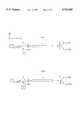
- FIG. 5is a schematic view of a device for carrying into effect the proposed method of switching of optical radiations having orthogonal polarizations showing a general pattern with pumping polarization along the optical axis of the object 4.
- FIG. 6same as in FIG. 5, with pumping polarization normal to the optical axis of the object 4.
- a positive technical result of the present inventionis expressed in a higher of amplification factor of a change in the signal intensity and provision of favorable conditions for creating an optical transistor, as well as devices based thereon.
- the polarization vector of a linearly polarized pumping, or of a signal polarized orthogonally to said pumpingis directed along an optical axis of a birefringent object 4 (an optical waveguide or a crystal), thereby eliminating a linear coupling between the radiations of orthogonal polarizations, and the pumping intensity is selected to be higher than the threshold value which can be found from the following formula:
- ⁇ --is the cubic nonlinear coefficient (factor) of the object
- the polarization vector of a linearly polarized pumping or of a linearly polarized signal orthogonal to said pumpingis deflected from the optical axis of the object by an angle lower than ⁇ /10, thereby establishing in the system a small linear coupling coefficient K between the radiations of orthogonal polarizations K ⁇
- a device for carrying said method into effectcomprising a birefringent object 4 (optical waveguide or crystal) and a polarizer 5 separating radiations of orthogonal polarizations, according to the invention, is also provided with a source 1 of pumping linearly polarized either along the optical axis of the object 4 or normal to said axis, a source 2 of signal linearly polarized either normal to said optical axis or along it, and a mixer 3, where a signal and a pumping are spatially coincided, the pumping intensity introduced into the object 4 is to be higher than the aforesaid threshold value.
- the devicehas a source of linearly polarized optical pumping radiation, having the polarization vector deflecting from the optical axis or from an axis orthogonal thereto, by an angle smaller than ⁇ /10.
- primemeans differentiating with respect to ⁇ z ⁇ /c
- Solution of (2)is determined by two key members for which the approximations hold true in the region of self-switching (cf., e.g., Transactions of the Academy of Sciences of the USSR, Ser.Phys., 1984, vol.48, No.7, pp.1441-1446): ##EQU5##
- MQWmultiple-quantum-well
- the cross-sectional areais approximately 10 -7 cm 2 .
- the waveguide lengthis 1 cm.
- the pumping intensityis greater than 3 ⁇ (c/2 ⁇ ) ⁇ ( ⁇ n/
- the output power of the polarizer 5changes by about 1 mW in each polarization.
- the output power of the polarizer 5(FIGS. 3, 5, 6) changes by about 10 mW in each polarization with the signal power changing by 0.1 mcW.
- Used as a light-carrying conductormay be another multilayer (MQW) structure based on, e.g., In 1-x Ga x As y P 1-y , or also a nonmultilayer structure based, e.g., on GaAs, InSb, InAs, InP, an organic material, etc., having an adequately large cubic nonlinearity factor ⁇ >10 -12 e.s.u.
- the pumping and signal wavelengthsmust correspond to the transparent region of the preselected light-carrying conductor.
- a pumping with a wavelength ⁇ 0.5 ⁇ m generated by the argon laser 1 (FIGS. 5, 6) and polarized along the vertical axis (y)is introduced into the fiber guide 4 (FIGS. 4-6) having a birefringence of the order of 10 -7 ; ⁇ 10 -13 e.s.u.
- the cross-sectional areais approximately 10 -7 cm 2 .
- the length of the waveguideis 10 m.
- the pumping intensityis greater than 3 ⁇ (c/2 ⁇ ) ⁇ ( ⁇ n/
- a weak signal from the source 2(FIGS.
- the output power of the polarizer 5changes by about 20 mW with the signal power changing by 0.1 ⁇ W in each polarization.
- the present inventioncan find application in creating optical transistors, weak signal amplifiers, optic logical devices, repeaters in optical communication lines, optical modulators, laser gates, as well as for obtaining short pulses of optical relays and registers of ultraweak signals.
Landscapes
- Physics & Mathematics (AREA)
- Nonlinear Science (AREA)
- General Physics & Mathematics (AREA)
- Optics & Photonics (AREA)
- Optical Communication System (AREA)
- Variable-Direction Aerials And Aerial Arrays (AREA)
- Semiconductor Lasers (AREA)
- Optical Modulation, Optical Deflection, Nonlinear Optics, Optical Demodulation, Optical Logic Elements (AREA)
Abstract
Description
I.sub.p >2|θ|.sup.-1 |α|,
γ+ρ=|I.sub.n |, (3)
I.sub.nM (1-ξ.sub.0.sup.2 -η.sub.0.sup.2)=2 αξ.sub.0 +Kη.sub.0 +γsign(θ)! (4)
|I.sub.n |>γIIξ.sub.0 =-sign(θ)sign(α), η.sub.0 =0. (6)
T.sub.x,min =0,T.sub.x,max =ΔT=1-γ/|I.sub.n |=1-3/(4R.sub.y).
Claims (13)
I.sub.p >2(c/2π)|θ|.sup.-1 |α|
Applications Claiming Priority (3)
| Application Number | Priority Date | Filing Date | Title |
|---|---|---|---|
| RU94025344ARU2114453C1 (en) | 1994-07-05 | 1994-07-05 | Method for switching optical waves of orthogonal polarization |
| RU94025344 | 1994-07-05 | ||
| PCT/RU1995/000131WO1996001441A1 (en) | 1994-07-05 | 1995-06-21 | Method of switching orthogonally polarized optical beams and associated device |
Publications (1)
| Publication Number | Publication Date |
|---|---|
| US5793905Atrue US5793905A (en) | 1998-08-11 |
Family
ID=20158149
Family Applications (1)
| Application Number | Title | Priority Date | Filing Date |
|---|---|---|---|
| US08/776,204Expired - Fee RelatedUS5793905A (en) | 1994-07-05 | 1995-06-21 | Method and device for switching of optical radiations of orthogonal polarizations |
Country Status (5)
| Country | Link |
|---|---|
| US (1) | US5793905A (en) |
| EP (1) | EP0806695A4 (en) |
| JP (1) | JPH10507839A (en) |
| RU (1) | RU2114453C1 (en) |
| WO (1) | WO1996001441A1 (en) |
Cited By (8)
| Publication number | Priority date | Publication date | Assignee | Title |
|---|---|---|---|---|
| WO1998001777A3 (en)* | 1996-07-09 | 1999-02-25 | Corning Inc | Fiber optic system with simultaneous switching and raman |
| US5943453A (en)* | 1997-03-14 | 1999-08-24 | The Board Of Trustees Of The Leland Stanford Junior University | All fiber polarization splitting switch |
| US5946428A (en)* | 1996-07-09 | 1999-08-31 | Corning Incorporated | Fiber optic system with simultaneous switching and raman |
| US6449072B1 (en)* | 1997-01-31 | 2002-09-10 | Alcatel | Add/drop multiplexer |
| US20030103745A1 (en)* | 1997-06-13 | 2003-06-05 | Cleomen, Ltd. | Method and device for switching, amplification, controlling and modulation of optical radiation (variants) |
| US20030112484A1 (en)* | 2001-12-03 | 2003-06-19 | Dmitry Ponomarenko | Optical multi-gate device and method |
| US6762713B1 (en) | 2003-01-13 | 2004-07-13 | The United States Of America As Represented By The Secretary Of The Army | Device and method for determining all components of the stokes polarization vector with a radar signal |
| US7023546B1 (en) | 2003-10-21 | 2006-04-04 | The United States Of America As Represented By The Secretary Of The Army | Real-time imaging spectropolarimeter based on an optical modulator |
Families Citing this family (8)
| Publication number | Priority date | Publication date | Assignee | Title |
|---|---|---|---|---|
| RU2160459C2 (en)* | 1996-07-09 | 2000-12-10 | Корнинг Инкорпорейтед | Optical fiber switch |
| RU2153694C2 (en)* | 1998-01-23 | 2000-07-27 | Майер Александр Александрович | Method for change-over of amplification and modulation of unidirectional distributively coupled solutions of orthogonal polarizations |
| RU2120649C1 (en)* | 1997-06-13 | 1998-10-20 | Майер Оптикал Рисеч Энд Текнолоджис ГмбХ | Method of commutation and modulation of unidirectional distributively-coupled waves ( versions ) and device for its realization |
| KR20010013757A (en) | 1997-06-13 | 2001-02-26 | 메이어 알렉산더 알렉산드로비치 | Device for modulation of optical radiation and transmission of information |
| US6694103B1 (en) | 1997-09-19 | 2004-02-17 | Cleomen Ltd. | Method for switching, amplification and modulation of unidirectional distributively coupled pulses and waves |
| RU2153695C2 (en)* | 1998-06-10 | 2000-07-27 | Майер Александр Александрович | Method for change-over, control, amplification and modulation of optical radiations in square-nonlinear tunnel-coupled light pipes (modifications) |
| RU2153689C2 (en)* | 1998-06-11 | 2000-07-27 | Майер Александр Александрович | Method and device for change-over, amplification, control and modulation of optical radiation (modifications) |
| RU2246177C2 (en)* | 2002-11-19 | 2005-02-10 | Майер Александр Александрович | Data transfer method for optical communication system (alternatives) |
Citations (6)
| Publication number | Priority date | Publication date | Assignee | Title |
|---|---|---|---|---|
| GB2125543A (en)* | 1982-07-23 | 1984-03-07 | Tokyo Shibaura Electric Co | Birefringence type measuring device |
| EP0198245A1 (en)* | 1985-03-18 | 1986-10-22 | Nec Corporation | Polarization controlling device comprising a beam splitter |
| US4919522A (en)* | 1988-02-25 | 1990-04-24 | Geo-Centers, Inc. | Optical switch having birefringent element |
| JPH0336407A (en)* | 1989-05-17 | 1991-02-18 | Westinghouse Electric Corp <We> | Reheat system and method for improving heat consumption thereof |
| US5090824A (en)* | 1990-07-31 | 1992-02-25 | Geo-Centers, Inc. | Fast optical switch having reduced light loss |
| US5305136A (en)* | 1992-03-31 | 1994-04-19 | Geo-Centers, Inc. | Optically bidirectional fast optical switch having reduced light loss |
Family Cites Families (3)
| Publication number | Priority date | Publication date | Assignee | Title |
|---|---|---|---|---|
| JP2980723B2 (en)* | 1990-06-01 | 1999-11-22 | キヤノン株式会社 | Optical amplifier |
| JPH0545682A (en)* | 1991-08-14 | 1993-02-26 | Fujitsu Ltd | Optical amplifier |
| US5274246A (en)* | 1992-05-04 | 1993-12-28 | The United States Of America As Represented By The Secretary Of The Air Force | Optical modulation and switching with enhanced third order nonlinearity multiple quantum well effects |
- 1994
- 1994-07-05RURU94025344Apatent/RU2114453C1/ennot_activeIP Right Cessation
- 1995
- 1995-06-21WOPCT/RU1995/000131patent/WO1996001441A1/ennot_activeApplication Discontinuation
- 1995-06-21EPEP95923618Apatent/EP0806695A4/ennot_activeCeased
- 1995-06-21JPJP8503811Apatent/JPH10507839A/enactivePending
- 1995-06-21USUS08/776,204patent/US5793905A/ennot_activeExpired - Fee Related
Patent Citations (6)
| Publication number | Priority date | Publication date | Assignee | Title |
|---|---|---|---|---|
| GB2125543A (en)* | 1982-07-23 | 1984-03-07 | Tokyo Shibaura Electric Co | Birefringence type measuring device |
| EP0198245A1 (en)* | 1985-03-18 | 1986-10-22 | Nec Corporation | Polarization controlling device comprising a beam splitter |
| US4919522A (en)* | 1988-02-25 | 1990-04-24 | Geo-Centers, Inc. | Optical switch having birefringent element |
| JPH0336407A (en)* | 1989-05-17 | 1991-02-18 | Westinghouse Electric Corp <We> | Reheat system and method for improving heat consumption thereof |
| US5090824A (en)* | 1990-07-31 | 1992-02-25 | Geo-Centers, Inc. | Fast optical switch having reduced light loss |
| US5305136A (en)* | 1992-03-31 | 1994-04-19 | Geo-Centers, Inc. | Optically bidirectional fast optical switch having reduced light loss |
Non-Patent Citations (4)
| Title |
|---|
| Quantum Electronics, 1982, vol. 9, No. 11, pp. 2296 2302.* |
| Quantum Electronics, 1982, vol. 9, No. 11, pp. 2296-2302. |
| Transactions of the Academy of Sciences of the USSR, Ser. Phys., 1984, vol. 48, No., 7, pp. 1441 1446.* |
| Transactions of the Academy of Sciences of the USSR, Ser. Phys., 1984, vol. 48, No., 7, pp. 1441-1446. |
Cited By (13)
| Publication number | Priority date | Publication date | Assignee | Title |
|---|---|---|---|---|
| WO1998001777A3 (en)* | 1996-07-09 | 1999-02-25 | Corning Inc | Fiber optic system with simultaneous switching and raman |
| US5946428A (en)* | 1996-07-09 | 1999-08-31 | Corning Incorporated | Fiber optic system with simultaneous switching and raman |
| US6449072B1 (en)* | 1997-01-31 | 2002-09-10 | Alcatel | Add/drop multiplexer |
| US5943453A (en)* | 1997-03-14 | 1999-08-24 | The Board Of Trustees Of The Leland Stanford Junior University | All fiber polarization splitting switch |
| US6128422A (en)* | 1997-03-14 | 2000-10-03 | The Board Of Trustees Of The Leland Stanford Junior University | All fiber polarization splitting switch |
| US6580859B1 (en)* | 1997-06-13 | 2003-06-17 | Cleomen Ltd. | Method and device for switching, amplification, controlling and modulation of optical radiation |
| US20030103745A1 (en)* | 1997-06-13 | 2003-06-05 | Cleomen, Ltd. | Method and device for switching, amplification, controlling and modulation of optical radiation (variants) |
| US20030112484A1 (en)* | 2001-12-03 | 2003-06-19 | Dmitry Ponomarenko | Optical multi-gate device and method |
| US20050211881A1 (en)* | 2001-12-03 | 2005-09-29 | Lroptics, Inc. | Optical multi-gate device and method |
| US7053359B2 (en) | 2001-12-03 | 2006-05-30 | Dmitry Ponomarenko | Optical multi-gate device and method |
| US6762713B1 (en) | 2003-01-13 | 2004-07-13 | The United States Of America As Represented By The Secretary Of The Army | Device and method for determining all components of the stokes polarization vector with a radar signal |
| US6967617B1 (en) | 2003-01-13 | 2005-11-22 | The United States Of America As Represented By The Secretary Of The Army | Polarization correlation signal processing for radiometers, ladars, and radars |
| US7023546B1 (en) | 2003-10-21 | 2006-04-04 | The United States Of America As Represented By The Secretary Of The Army | Real-time imaging spectropolarimeter based on an optical modulator |
Also Published As
| Publication number | Publication date |
|---|---|
| RU2114453C1 (en) | 1998-06-27 |
| EP0806695A1 (en) | 1997-11-12 |
| WO1996001441A1 (en) | 1996-01-18 |
| RU94025344A (en) | 1997-03-20 |
| EP0806695A4 (en) | 1998-05-06 |
| JPH10507839A (en) | 1998-07-28 |
Similar Documents
| Publication | Publication Date | Title |
|---|---|---|
| US5793905A (en) | Method and device for switching of optical radiations of orthogonal polarizations | |
| US5103494A (en) | Optoelectronic arrangement | |
| US5555326A (en) | Optical waveguide intensity modulator using electro-optic polymer | |
| EP0340779B1 (en) | Optical quantum interference device | |
| EP0817988B1 (en) | Polarization-insensitive, electro-optic modulator | |
| US5047822A (en) | Electro-optic quantum well device | |
| US20080037996A1 (en) | Compact systems for generating polarization-entangled photons | |
| EP1215528A2 (en) | Optical switch having a saturable absorber | |
| US6571028B1 (en) | Optical switch having a saturable absorber | |
| US5076658A (en) | Non-linear optical polymeric fiber waveguides | |
| US5485014A (en) | Multiple quantum well birefringent spatial light modulator | |
| JPH0758375B2 (en) | Polarization independent photoelectron directional coupler | |
| US5150242A (en) | Integrated optical computing elements for processing and encryption functions employing non-linear organic polymers having photovoltaic and piezoelectric interfaces | |
| JP2002511155A (en) | Method and apparatus for switching, amplifying, controlling and modulating optical radiation (version) | |
| KR100472056B1 (en) | Polarization-independent optical polymeric intensity modulator | |
| US5202941A (en) | Four section optical coupler | |
| US5381260A (en) | Uniaxially strained semiconductor multiple quantum well device using direction-dependent thermal expansion coefficients in a host substrate | |
| EP1536273A1 (en) | Polarization-independent electro-optic modulator | |
| Tong | Electro-optic waveguides | |
| RU2153694C2 (en) | Method for change-over of amplification and modulation of unidirectional distributively coupled solutions of orthogonal polarizations | |
| Wang et al. | All-optical XOR and NXOR logic gate implementation method based on dual-parallel phase modulators | |
| RU2153689C2 (en) | Method and device for change-over, amplification, control and modulation of optical radiation (modifications) | |
| US5815628A (en) | Ordered semiconductor having periodical disorder and devices made therefrom | |
| RU2153688C2 (en) | Method for change-over, modulation, amplification and control and line optical switch, modulator, amplifier and control element | |
| Al Graiti et al. | Optical hysteresis shape transformation using linear polarization components |
Legal Events
| Date | Code | Title | Description |
|---|---|---|---|
| AS | Assignment | Owner name:TOVARISCHESTVO S OGRANICHENNOI OTVETSTVENNOSTYU "O Free format text:ASSIGNMENT OF ASSIGNORS INTEREST;ASSIGNORS:MAIER, ALEXANDR A.;SITARSKY, KONSTANTIN Y.;REEL/FRAME:008647/0581 Effective date:19970115 | |
| AS | Assignment | Owner name:MAIER OPTICAL RESEARCH AND TECHNOLOGIES GMBH, SWIT Free format text:ASSIGNMENT OF ASSIGNORS INTEREST;ASSIGNOR:TOVARISCHESTVO S. ORGANICHENNOI OTVETSTVENNOSTYU "OPTRAN";REEL/FRAME:008925/0430 Effective date:19980105 | |
| AS | Assignment | Owner name:MAIER OPTICAL RESEARCH AND TECHNOLOGIES GMBH, SWIT Free format text:ASSIGNMENT OF ASSIGNORS INTEREST;ASSIGNORS:ORGANICHENNOI, TOVARISCHESTVO S.;OPTRAN, OTVETSTVENNOSTYU;REEL/FRAME:008999/0294 Effective date:19980105 | |
| AS | Assignment | Owner name:CLEOMEN LTD., RUSSIAN FEDERATION Free format text:ASSIGNMENT OF ASSIGNORS INTEREST;ASSIGNOR:MAIER OPTICAL RESEARCH AND TECHNOLOGIES GMBH;REEL/FRAME:010936/0240 Effective date:20000602 | |
| FPAY | Fee payment | Year of fee payment:4 | |
| REMI | Maintenance fee reminder mailed | ||
| LAPS | Lapse for failure to pay maintenance fees | ||
| STCH | Information on status: patent discontinuation | Free format text:PATENT EXPIRED DUE TO NONPAYMENT OF MAINTENANCE FEES UNDER 37 CFR 1.362 | |
| FP | Lapsed due to failure to pay maintenance fee | Effective date:20060811 |