US5793809A - Transparent technique for Mu-law modems to detect an all-digital circuit connection - Google Patents
Transparent technique for Mu-law modems to detect an all-digital circuit connectionDownload PDFInfo
- Publication number
- US5793809A US5793809AUS08/457,881US45788195AUS5793809AUS 5793809 AUS5793809 AUS 5793809AUS 45788195 AUS45788195 AUS 45788195AUS 5793809 AUS5793809 AUS 5793809A
- Authority
- US
- United States
- Prior art keywords
- sample
- signal
- probe signal
- pulse code
- code modulated
- Prior art date
- Legal status (The legal status is an assumption and is not a legal conclusion. Google has not performed a legal analysis and makes no representation as to the accuracy of the status listed.)
- Expired - Fee Related
Links
- 238000000034methodMethods0.000titleclaimsdescription35
- 239000000523sampleSubstances0.000claimsabstractdescription99
- 238000001514detection methodMethods0.000claimsabstractdescription14
- 230000006854communicationEffects0.000claimsdescription22
- 238000004891communicationMethods0.000claimsdescription21
- 230000005540biological transmissionEffects0.000claimsdescription16
- 238000012544monitoring processMethods0.000claims5
- 238000012986modificationMethods0.000abstractdescription10
- 230000004048modificationEffects0.000abstractdescription10
- 238000010586diagramMethods0.000description8
- 230000011664signalingEffects0.000description6
- 230000008569processEffects0.000description5
- 230000008901benefitEffects0.000description4
- 230000007704transitionEffects0.000description3
- 238000009432framingMethods0.000description2
- 238000013459approachMethods0.000description1
- 238000006243chemical reactionMethods0.000description1
- 238000012790confirmationMethods0.000description1
- 230000006735deficitEffects0.000description1
- 238000002592echocardiographyMethods0.000description1
- 230000008030eliminationEffects0.000description1
- 238000003379elimination reactionMethods0.000description1
- 230000006870functionEffects0.000description1
- 230000001771impaired effectEffects0.000description1
- 238000012545processingMethods0.000description1
- 238000012552reviewMethods0.000description1
- 238000005070samplingMethods0.000description1
- 238000012360testing methodMethods0.000description1
Images


Classifications
- H—ELECTRICITY
- H04—ELECTRIC COMMUNICATION TECHNIQUE
- H04L—TRANSMISSION OF DIGITAL INFORMATION, e.g. TELEGRAPHIC COMMUNICATION
- H04L5/00—Arrangements affording multiple use of the transmission path
- H04L5/14—Two-way operation using the same type of signal, i.e. duplex
- H04L5/1438—Negotiation of transmission parameters prior to communication
- H—ELECTRICITY
- H04—ELECTRIC COMMUNICATION TECHNIQUE
- H04B—TRANSMISSION
- H04B14/00—Transmission systems not characterised by the medium used for transmission
- H04B14/02—Transmission systems not characterised by the medium used for transmission characterised by the use of pulse modulation
- H04B14/04—Transmission systems not characterised by the medium used for transmission characterised by the use of pulse modulation using pulse code modulation
- H04B14/046—Systems or methods for reducing noise or bandwidth
- H04B14/048—Non linear compression or expansion
- H—ELECTRICITY
- H04—ELECTRIC COMMUNICATION TECHNIQUE
- H04L—TRANSMISSION OF DIGITAL INFORMATION, e.g. TELEGRAPHIC COMMUNICATION
- H04L25/00—Baseband systems
- H04L25/38—Synchronous or start-stop systems, e.g. for Baudot code
- H04L25/40—Transmitting circuits; Receiving circuits
- H04L25/49—Transmitting circuits; Receiving circuits using code conversion at the transmitter; using predistortion; using insertion of idle bits for obtaining a desired frequency spectrum; using three or more amplitude levels ; Baseband coding techniques specific to data transmission systems
- H04L25/4917—Transmitting circuits; Receiving circuits using code conversion at the transmitter; using predistortion; using insertion of idle bits for obtaining a desired frequency spectrum; using three or more amplitude levels ; Baseband coding techniques specific to data transmission systems using multilevel codes
- H04L25/4927—Transmitting circuits; Receiving circuits using code conversion at the transmitter; using predistortion; using insertion of idle bits for obtaining a desired frequency spectrum; using three or more amplitude levels ; Baseband coding techniques specific to data transmission systems using multilevel codes using levels matched to the quantisation levels of the channel
- H—ELECTRICITY
- H04—ELECTRIC COMMUNICATION TECHNIQUE
- H04Q—SELECTING
- H04Q2213/00—Indexing scheme relating to selecting arrangements in general and for multiplex systems
- H04Q2213/13031—Pulse code modulation, PCM
- H—ELECTRICITY
- H04—ELECTRIC COMMUNICATION TECHNIQUE
- H04Q—SELECTING
- H04Q2213/00—Indexing scheme relating to selecting arrangements in general and for multiplex systems
- H04Q2213/13093—Personal computer, PC
- H—ELECTRICITY
- H04—ELECTRIC COMMUNICATION TECHNIQUE
- H04Q—SELECTING
- H04Q2213/00—Indexing scheme relating to selecting arrangements in general and for multiplex systems
- H04Q2213/13107—Control equipment for a part of the connection, distributed control, co-processing
- H—ELECTRICITY
- H04—ELECTRIC COMMUNICATION TECHNIQUE
- H04Q—SELECTING
- H04Q2213/00—Indexing scheme relating to selecting arrangements in general and for multiplex systems
- H04Q2213/13174—Data transmission, file transfer
- H—ELECTRICITY
- H04—ELECTRIC COMMUNICATION TECHNIQUE
- H04Q—SELECTING
- H04Q2213/00—Indexing scheme relating to selecting arrangements in general and for multiplex systems
- H04Q2213/13199—Modem, modulation
- H—ELECTRICITY
- H04—ELECTRIC COMMUNICATION TECHNIQUE
- H04Q—SELECTING
- H04Q2213/00—Indexing scheme relating to selecting arrangements in general and for multiplex systems
- H04Q2213/13204—Protocols
- H—ELECTRICITY
- H04—ELECTRIC COMMUNICATION TECHNIQUE
- H04Q—SELECTING
- H04Q2213/00—Indexing scheme relating to selecting arrangements in general and for multiplex systems
- H04Q2213/1322—PBX
- H—ELECTRICITY
- H04—ELECTRIC COMMUNICATION TECHNIQUE
- H04Q—SELECTING
- H04Q2213/00—Indexing scheme relating to selecting arrangements in general and for multiplex systems
- H04Q2213/13292—Time division multiplexing, TDM
- H—ELECTRICITY
- H04—ELECTRIC COMMUNICATION TECHNIQUE
- H04Q—SELECTING
- H04Q2213/00—Indexing scheme relating to selecting arrangements in general and for multiplex systems
- H04Q2213/13396—Signaling in general, in-band signalling
Definitions
- the present inventionrelates to data communications equipment, e.g., modems, and, more particularly, to Mu-law modems.
- a "Mu-law modem”is identical to an analog modem with the exception that the Mu-law modem does not have an analog interface to the public switched telephone network (PSTN). Instead, the Mu-law modem couples to the PSTN via a digital interface.
- PSTNpublic switched telephone network
- an end userutilizes a Mu-law modem behind a customer-premises private branch exchange (PBX), which itself is connected to the PSTN via wideband digital facilities like T1, etc.
- PBXcustomer-premises private branch exchange
- the Mu-law modemcan be coupled to the PBX over in-house wiring or the modem can be physically resident in the PBX itself.
- the Mu-law modemWhether coupled to the PBX or physically in the PBX, the Mu-law modem generates a 64 thousand bit per second (kbps) DS0 data stream for transmission through the PSTN to a far-end, or remote, data endpoint of a data connection.
- this DS0 data streamis a sequence of pulse-code modulated (PCM) samples using the same analog-to-digital sampling and encoding technique used by the PSTN for transmission of voice-band signals through the PSTN.
- the digital signal processor of the Mu-law modemuses either of the standard companding encoding schemes, Mu-law or A-law, as defined in CCITT Recommendation G.711, to produce the DS0 data stream.
- This DS0 data streamtransits the PSTN exactly like those DS0 streams created at the central office/local loop interface of the PSTN.
- Mu-law modemis the possibility of data transmission at speeds approaching the DS0 data rate.
- thisrequires a completely digital connection between the two data endpoints--which cannot be guaranteed.
- the PSTNitself might include an analog facility as part of the data connection.
- the other data endpointis typically coupled to the PSTN via an analog local loop, which results in the DS0 data stream being converted back to a voice-band analog signal.
- the actual data rate of the data connectionis limited to standard analog-based data transmission rates.
- the PSTNdoes not provide notification to a Mu-law modem when the data connection is entirely digital.
- a Mu-law modemcannot determine when an all-digital connection exists. Consequently, a Mu-law modem is limited to standard analog-based data transmission unless a priori a particular data connection is known to be all-digital. Such a situation might exist in a dedicated "point-to-point" data connection. In this instance, the Mu-law modem can be manually administered to a digital mode of operation.
- a probe signalis transmitted from one Mu-law modem to the other Mu-law modem.
- This probe signalis selected such that the presence of an analog link distorts the probe signal--with the result that the probe signal can no longer be reliably detected by the receiving DCE.
- reception and detection of this probe signal by the other Mu-law modemensures to a degree the existence of an all-digital connection.
- the Mu-law modemscan then switch to transmission of data in purely digital form thereby increasing the maximum possible data rate to 56 kbps or more.
- the transmitting Mu-law modemcreates this probe signal by modifying the 7th bit of each of a number of PCM samples during the "hand-shaking" phase of the data connection. Furthermore, the transmitting Mu-law modem only makes this modification on those PCM samples that fall into the range of segment one as defined in CCITT Recommendation G.711. Similarly, the receiving Mu-law modem searches for this known pattern. Upon detection of this pattern, the receiving Mu-law modem provides an acknowledgment signal and both modems subsequently switch to a digital-mode of operation. On the other hand, if, in fact, there is a least one analog link in the data connection, the probe signal becomes distorted and, since the receiving Mu-law modem does not detect the probe signal, handshaking is completed in the standard fashion.
- the above-described techniqueis "transparent.”
- transparentmeans that if a modem using this technique is connected via a data connection with one or more analog spans or is connected to a modem which has not implemented this technique, normal operation in the standard manner of a dial modem is not impaired. For example, if the receiving modem is a standard analog modem or is not a compatible Mu-law modem, the contents of this low significance bit simply resembles noise and, again, handshaking is completed in the standard fashion.
- FIG. 1is a block diagram of a switched point-to-point data communications system embodying the principles of the invention
- FIG. 2is a block diagram of data communications equipment 200 embodying the principles of the invention
- FIG. 3is a flow diagram of an illustrative method embodying the principles of the invention for use in originating data communications equipment;
- FIG. 4is a flow diagram of an illustrative method embodying the principles of the invention for use in answering data communications equipment;
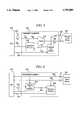
- FIG. 5is a block diagram of transmit element 250 of data communications equipment 200.
- FIG. 6is a block diagram of receiver element 240 of data communications equipment 200.
- FIG. 1A switched point-to-point data communications system embodying the principles of the invention is shown in FIG. 1.
- DTEdata terminal equipment
- DCEdata communications equipment
- T1 Interface 15PSTN 10, T1 interface 25, and DCE 100.
- both DCE 200 and DCE 100are Mu-law modems.
- each DTEis a personal computer.
- the communications channelincludes PSTN 10, and T1 facilities 101 and 201, which are representative of digital facilities.
- T1 facility 201terminates in T1 interface 15, which is assumed to be co-located with DCE 200.
- T1 interface 15can be a stand-alone piece of equipment or part of a digital PBX.
- T1 facility 201conveys a T1 signal from the respective terminating central office (not show) within PSTN 10.
- a T1 signalincludes a plurality of channels, only one of which is assigned to DCE 200.
- T1 facility 201is actually shared among a plurality of DCEs, of which DCE 200 is one.
- these other DCEsaccess T1 facility 201 via time-division-multiplexed (TDM) bus 261 and T1 interface 15.
- TDMtime-division-multiplexed
- DCE 200is a Mu-law modem, which is shown in block diagram form in FIG. 2.
- DCE 200comprises memory 220, CPU 210, Digital Signal Processor (DSP) 230, time-slot access device 260, and data terminal equipment interface 270.
- DCE 200also includes transmit element 250 and receiver element 240.
- CPU 210is a microprocessor-based central processing unit, which operates on, or executes, program data stored in memory 220, via path 213.
- Memory 220is representative of random access memory (RAM), and comprises a number of representative storage locations, of which a subset is shown in FIG. 2.
- storage location 505corresponds to that portion of memory that stores instructions and data associated with implementing step 505 of FIG. 3, described below.
- Time slot access device 260provides information to, and receives information from, T1 interface 15, via TDM bus 261.
- time slot access device 260receives signaling information from T1 interface 15, via TDM bus 261.
- This signaling informationincludes the identification of the particular time slot of TDM bus 261 that is assigned to DCE 200 and includes other information like "Automatic Number Identification" (ANI), which represents the calling party's telephone number.
- ANIAutomatic Number Identification
- Time slot access device 260both removes and inserts data into the assigned time slot of TDM bus 261. This data is the above-described PCM signal.
- data extracted by time slot access device 260 from the assigned time slotis provided as a received signal, RX, to DSP 230 via line 241, block 240 and line 242.
- the received signal, RXis a received form of the data signal transmitted by far-end DCE 100.
- DSP 230applies transmit signal TX to time slot access device 260, via line 232, transmit element 250 (described below), and line 251 for transmission to the far end.
- a probe signalis transmitted from one Mu-law modem to the other Mu-law modem. Reception and detection of this probe signal by the other Mu-law modem ensures to a degree the existence of an all-digital connection.
- the probe signalis selected such that the presence of an analog link distorts the probe signal--with the result that the probe signal can no longer be reliably detected by the receiving DCE.
- This inventive conceptallows a Mu-law modem to "test" for an all-digital connection at the same time it is communicating using standard analog techniques. This is done in a way which does not interfere with the standard communication process.
- FIGS. 3 and 4show illustrative methods for use in originating and answering DCEs in accordance with the principles of the invention.
- FIG. 3 and FIG. 4represent a simple interlocked handshake to provide positive confirmation of mutual recognition of an all-digital connection. Other methods are also possible. Since FIG. 4 is similar to FIG. 3, except for use in an answering DCE, only FIG. 3 is described in detail below.
- DCE 200begins in an idle mode in step 505.
- DCE 200initiates a data call to DTE 60.
- this data callcan be initiated in a number of ways, e.g., a user at DTE 50 can keyboard dial using the well-known "AT-command set.”
- DCE 200waits for the standard answer tone, which DCE 100 provides upon answering the data call. If no answer tone is detected, DCE 200 disconnects in step 520, e.g., after a suitable time-out.
- DCE 200upon detection of an answer tone, begins handshaking in accordance with any one of a number of analog modem standards, e.g., CCITT V.32 bis, and, in accordance with the inventive concept, adds a probe signal in step 525 to any handshaking signals.
- the probe signalis a sequence of scrambled marks for a period of time T 1 (described further below).
- T 1time of time
- DCE 200continues the handshaking process, and the transmission of the probe signal, and further monitors for reception of a corresponding probe signal representing scrambled marks transmitted from DCE 100 in step 530.
- DCE 200simply establishes the data connection in accordance with the respective analog standard, e.g., V.32 bis, in step 535. Since, in this example, both DCE 100 and DCE 200 embody the inventive concept, the lack of detection of a probe signal by DCE 200 is representative of the data connection taking path 12, which contains at least one analog link, through PSTN 10. (Also, if DCE 100 did not embody the inventive concept, the lack of a detected probe signal could be due to DCE 100 simply being incompatible with the inventive technique, e.g., DCE 100 is a standard analog modem or a Mu-law modem that does not embody the inventive concept.)
- DCE 200continues the standard handshaking and changes the probe signal to a sequence of scrambled spaces for a time period T 3 in step 540.
- DCE 200continues the handshaking process, and the transmission of the probe signal representing now scrambled spaces, and further monitors for reception of a corresponding probe signal representing scrambled spaces transmitted from DCE 100 in step 545. If no received probe signal is detected for a period of time T 4 , DCE 200 simply establishes the data connection in accordance with the respective analog standard, e.g., V.32 bis, in step 535.
- DCE 200terminates the standard handshaking procedure and switches to an all-digital mode of operation in step 550. Detection of this sequence of probe signals by DCE 200 is representative of the data connection taking path 11 (shown in FIG. 1), which is an all-digital connection to DCE 100. After switching to an all-digital mode of operation, transmission of data occurs in purely digital form as known in the art thereby increasing the maximum possible data rate to 56 kbps or more.
- transmit element 250 of DCE 200inserts the probe signal into the PCM data stream.
- An illustrative embodiment of transmit element 250is shown in block diagram form in FIG. 5.
- Transmit element 250includes selector 715, segment one detector 710, and sequence generator 705.
- the basic ideais simply for the transmitter of DCE 200 to modify the PCM data stream in a manner which results in the probe signal being interpreted as just noise by a receiving modem that is not "looking" for this pattern. This is done by imposing the modification on the bits in the PCM data stream that have the least significance when the data from the PCM signal is interpreted as a representation of an analog signal.
- the modificationis deterministic and has a bit error rate which is no worse than any of the other data, it can be recognized as a known pattern by a receiving Mu-law modem that embodies the inventive concept.
- transmit element 250modifies only the 7th bit of the PCM samples (based on bit numbering given in G.711). (It should be noted that bit 8 is not used because this is sometime used for inter-office signaling and framing, etc.) A means of identification of this bit is implicit in the required PCM framing. Furthermore, transmit element 250 only makes this modification on the samples which fall into the range of segment one (as defined in G.711) where the modifications have the least impact on the analog interpretation. (As defined in G.711, the higher the segment number of a PCM sample, the higher the signal level). Since the communication via these modifications requires very low bandwidth, the DCE 200 can use the opportunistic approach and wait for segment one samples to occur before applying the modification.
- the probe signal, or pattern, which is imposed on the 7th bit of the segment one samplesconsists of marks or spaces scrambled by a polynomial such as is typically used in modem scramblers and inter-DCE signaling techniques.
- the benefit of using this type of probe signalis that it resembles random data and can be easily detected with an almost arbitrarily low probability of false detection. If, in fact, the modem at the other end of the data connection is not sending the pattern, the contents of this low significance bit resembles a random data stream.
- the probe signalis corrupted by the analog conversion process so that again the contents of this low significance bit resembles a random data stream.
- the likelihood of false detection of the all-digital connectioncan be reduced to a suitable level by extending the length of the pattern required for detection.
- DSP 230generates a sequence of 8-bit PCM samples, at the standard 8 kHz rate, on line 232, which provides each PCM sample in parallel, i.e., each bit of the 8-bit sample is provided on a separate signal path. Seven of these signal paths are represented by line 704, which couples to time-slot access device 260. The remaining bit of information, conveyed by line 706, is applied to selector 715. The latter either selects the PCM bit generated by DSP 230, via line 706, or, in accordance with the inventive concept, selects the data generated by sequence generator 705, via line 711, for application to time-slot access device 260, via line 708.
- segment one detector 710The selection of the signal to convey to time-slot access device 260 is performed by segment one detector 710, which is also under the control of DSP 230. As will be appreciated by one skilled in the art from a review of FIG. 5, the segment one detector 710 generates a control signal 712 which controls the operation of the selector 715. Namely, the value of control signal 712 determines whether the selector 715 "selects" the value on line 711 (i.e., the probe signal) or the value on line 706 as the bit 7 value of the 8 bit PCM value that is sent to time-slot access device 260.
- DCE 200initially disables, via line 248, segment one detector 710, e.g., while in the idle mode.
- signal one detector 710causes selector 715 to convey the signal on line 706 to time-slot access device 260.
- DSP 230enables, via line 248, segment one detector 710, which then monitors for the occurrence of segment one samples on signal lines 707.
- segment one detector 710controls selector 715 so that the signal on line 711 is conveyed to time-slot access device 260.
- Segment one detector 710also provides a clock signal, via line 713, to sequence generator 705 to generate the signal on line 711 (ie., the probe signal), which now replaces the current bit 7 value of the 8-bit PCM value provided by DSP 230.
- the latteralso controls, via line 249, sequence generator 705 to generate a scrambled marks or scrambled spaces signal based on the phase of the inter-modem exchange as described above. Once the transition to either all-digital mode or a standard analog mode, DSP 230 disables segment one detector 710.
- receiver element 240 of DCE 200includes segment one detector 810 and sequence detector 805 as shown in FIG. 6.
- Time-slot access device 260provides a sequence of received 8-bit PCM samples in parallel form on line 241. Seven of the eight PCM bits are represented by line 807 and are applied to DSP 230 and to segment one detector 810. Bit 7 of the eight PCM bits is conveyed by line 806, which is applied to DSP 230 and to sequence detector 805.
- DSP 230enables segment one detector 810 via line 238.
- segment one detector 810When segment one detector 810 detects a segment one sample, it clocks sequence detector 805 via line 813. DSP 230 controls sequence detector 805 to search for either scrambled marks or spaces via line 239. When sequence detector 805 detects the required number of bits of either sequence, it informs the DSP 230 via control line 242. One illustrative value for the required number of bits is at least 30 scrambled marks or at least 30 scrambled spaces. DSP 230 then responds to this signal as described previously in accordance with FIGS. 3 or 4, appropriately.
- DSP 230determines whether a probe signal representing scrambled marks has been detected by sequence detector 805, via line 242, and keeps track, via a counter (not shown), whether scrambled marks have been detected for the required time intervals (if any).
- any one or more of those building blockscan be carried out using one or more appropriate programmed processors, e.g., a digital signal processor.
- the inventive techniquecan be used with any modulation scheme that provides duplex communication, and can also be used with voice communications as well, e.g., such as switching to voice plus video upon detection of the all-digital connection.
- a probe signalrepresented by a scrambled marks or a scrambled spaces signal
- other forms of probe signalsare possible.
- other modifications to the above-described handshaking methodare possible. For example, even after the transition to a digital mode of operation, the probe signal could still be transmitted as part of a preamble for the all digital data stream. This preamble could simply be a stream of continuous samples of the same value to which the probe signal is added for some brief period of time.
- the probe signalcould be inserted into other bits of a PCM sample.
- the probe signalcould be put into the seventh and eighth bits of a PCM sample.
Landscapes
- Engineering & Computer Science (AREA)
- Signal Processing (AREA)
- Computer Networks & Wireless Communication (AREA)
- Physics & Mathematics (AREA)
- Spectroscopy & Molecular Physics (AREA)
- Nonlinear Science (AREA)
- Quality & Reliability (AREA)
- Communication Control (AREA)
- Telephonic Communication Services (AREA)
Abstract
Description
Claims (8)
Priority Applications (1)
| Application Number | Priority Date | Filing Date | Title |
|---|---|---|---|
| US08/457,881US5793809A (en) | 1995-05-31 | 1995-05-31 | Transparent technique for Mu-law modems to detect an all-digital circuit connection |
Applications Claiming Priority (1)
| Application Number | Priority Date | Filing Date | Title |
|---|---|---|---|
| US08/457,881US5793809A (en) | 1995-05-31 | 1995-05-31 | Transparent technique for Mu-law modems to detect an all-digital circuit connection |
Publications (1)
| Publication Number | Publication Date |
|---|---|
| US5793809Atrue US5793809A (en) | 1998-08-11 |
Family
ID=23818450
Family Applications (1)
| Application Number | Title | Priority Date | Filing Date |
|---|---|---|---|
| US08/457,881Expired - Fee RelatedUS5793809A (en) | 1995-05-31 | 1995-05-31 | Transparent technique for Mu-law modems to detect an all-digital circuit connection |
Country Status (1)
| Country | Link |
|---|---|
| US (1) | US5793809A (en) |
Cited By (36)
| Publication number | Priority date | Publication date | Assignee | Title |
|---|---|---|---|---|
| US5970103A (en)* | 1996-09-06 | 1999-10-19 | Townshend; Brent | High speed communications system for analog subscriber connections |
| WO2000007353A1 (en)* | 1998-07-28 | 2000-02-10 | Conexant Systems, Inc. | Method and apparatus for detecting and determining characteristics of a digital channel in a data communication system |
| WO2000019768A1 (en)* | 1998-09-30 | 2000-04-06 | Conexant Systems, Inc. | Method and apparatus for identifying the encoding type of a central office codec |
| EP1001579A1 (en)* | 1998-11-10 | 2000-05-17 | Siemens Aktiengesellschaft | Method and apparatus for determining properties of a signal transmission channel |
| US6104730A (en)* | 1997-11-25 | 2000-08-15 | International Business Machines Corporation | System, method and article of manufacture for high bit rate access over robbed bit trunks |
| US6111922A (en)* | 1994-12-20 | 2000-08-29 | Sgs-Thomson Microelectronics S.A. | Circuit for detecting word sequences in a modem |
| US6141403A (en)* | 1997-08-13 | 2000-10-31 | International Business Machines Corporation | Modem protocol |
| US6178185B1 (en) | 1997-11-25 | 2001-01-23 | International Business Machines Corporation | Network interface device, method and article of manufacture for providing high bit rate access over robbed bit |
| US6212228B1 (en)* | 1997-09-10 | 2001-04-03 | Nortel Networks Limited | Apparatus for modulation and demodulating digital data |
| US6212263B1 (en)* | 1998-09-30 | 2001-04-03 | Compaq Computer Corporation | 5 volts single power supply ADSL analog front end design |
| US6341360B1 (en) | 1999-03-08 | 2002-01-22 | International Business Machines Corporation | Decision feedback equalizers, methods, and computer program products for detecting severe error events and preserving equalizer filter characteristics in response thereto |
| US6381267B1 (en) | 1999-03-08 | 2002-04-30 | International Business Machines Corporation | Modems, methods, and computer program products for falling back to a lower data rate protocol upon detecting abnormal line conditions during startup |
| US6389064B1 (en) | 1999-03-08 | 2002-05-14 | International Business Machines Corporation | Modems, methods, and computer program products for identifying a signaling alphabet in variance with an ideal alphabet due to digital impairments |
| US6487243B1 (en) | 1999-03-08 | 2002-11-26 | International Business Machines Corporation | Modems, methods, and computer program products for recovering from errors in a tone reversal sequence between two modems |
| US6504865B1 (en) | 1999-02-24 | 2003-01-07 | Altocom, Inc. | Digital connection detection technique |
| US6505222B1 (en) | 1999-10-29 | 2003-01-07 | International Business Machines Corporation | Systems methods and computer program products for controlling undesirable bias in an equalizer |
| US6553518B1 (en) | 1999-03-08 | 2003-04-22 | International Business Machines Corporation | Severe error detectors, methods and computer program products that use constellation specific error event thresholds to detect severe error events during demodulation of a signal comprising symbols from a plurality of symbol constellations |
| US6611563B1 (en) | 1999-10-29 | 2003-08-26 | International Business Machines Corporation | Systems, methods and computer program products for data mode refinement of modem constellation points |
| EP0954158A3 (en)* | 1998-04-28 | 2003-10-29 | Lucent Technologies Inc. | Data optimized codec |
| US6650657B1 (en) | 1999-10-29 | 2003-11-18 | International Business Machines Corporation | Systems, methods and computer program products for identifying digital impairments in modem signals |
| US6661837B1 (en) | 1999-03-08 | 2003-12-09 | International Business Machines Corporation | Modems, methods, and computer program products for selecting an optimum data rate using error signals representing the difference between the output of an equalizer and the output of a slicer or detector |
| US6661847B1 (en) | 1999-05-20 | 2003-12-09 | International Business Machines Corporation | Systems methods and computer program products for generating and optimizing signal constellations |
| US6662322B1 (en) | 1999-10-29 | 2003-12-09 | International Business Machines Corporation | Systems, methods, and computer program products for controlling the error rate in a communication device by adjusting the distance between signal constellation points |
| USRE38391E1 (en) | 1993-12-23 | 2004-01-20 | Stmicroelectronics S.A. | Circuit for detecting word sequences in a modem |
| US6754187B1 (en) | 2000-04-06 | 2004-06-22 | Inter-Tel, Inc. | Performance enhancement system for digital PBX |
| US6754258B1 (en) | 1999-10-29 | 2004-06-22 | International Business Machines Corporation | Systems, methods and computer program products for averaging learned levels in the presence of digital impairments based on patterns |
| US6765955B1 (en) | 1999-10-29 | 2004-07-20 | International Business Machines Corporation | Methods, systems and computer program products establishing a communication configuration for a modem connection to compensate for echo noise |
| US6792040B1 (en) | 1999-10-29 | 2004-09-14 | International Business Machines Corporation | Modems having a dual power mode capability and methods of operating same |
| US6792004B1 (en) | 1999-10-29 | 2004-09-14 | International Business Machines Corporation | Systems, methods and computer program products for averaging learned levels in the presence of robbed-bit signaling based on proximity |
| US6816545B1 (en) | 1999-10-29 | 2004-11-09 | International Business Machines Corporation | Systems, methods and computer program products for identifying digital impairments in modems based on clusters and/or skips in pulse code modulation signal levels |
| US6823004B1 (en) | 1999-10-29 | 2004-11-23 | International Business Machines Corporation | Methods, systems and computer program products for monitoring performance of a modem during a connection |
| US6823017B1 (en) | 1999-10-29 | 2004-11-23 | International Business Machines Corporation | Systems, methods and computer program products for filtering glitches from measured values in a sequence of code points |
| US6826157B1 (en) | 1999-10-29 | 2004-11-30 | International Business Machines Corporation | Systems, methods, and computer program products for controlling data rate reductions in a communication device by using a plurality of filters to detect short-term bursts of errors and long-term sustainable errors |
| US6839382B1 (en) | 1999-10-29 | 2005-01-04 | International Business Machines Corporation | System, methods and computer program products for identifying digital impairments in modem signals using signature analysis and signal level comparison analysis |
| US6967995B1 (en) | 1999-10-29 | 2005-11-22 | International Business Machines Corporation | Methods, systems and computer program products for carrier drop detection using a variable threshold |
| US7003030B2 (en) | 1999-03-08 | 2006-02-21 | Lenovo (Singapore) Pte. Ltd. | Receivers, methods, and computer program products for an analog modem that receives data signals from a digital modem |
Citations (6)
| Publication number | Priority date | Publication date | Assignee | Title |
|---|---|---|---|---|
| US5214637A (en)* | 1991-04-15 | 1993-05-25 | Codex Corporation | High speed two wire modem |
| US5267300A (en)* | 1991-10-07 | 1993-11-30 | Racal-Datacom, Inc. | High speed digital data transmission over switched voice network |
| US5311578A (en)* | 1992-05-07 | 1994-05-10 | At&T Bell Laboratories | Technique for automatic identification of a remote modem |
| US5448574A (en)* | 1991-02-21 | 1995-09-05 | Nec Corporation | Detection system for abnormal cable connections in communication apparatuses |
| US5463661A (en)* | 1995-02-23 | 1995-10-31 | Motorola, Inc. | TX preemphasis filter and TX power control based high speed two wire modem |
| US5528679A (en)* | 1994-01-27 | 1996-06-18 | Primary Access Corporation | Automatic detection of digital call paths in a telephone system |
- 1995
- 1995-05-31USUS08/457,881patent/US5793809A/ennot_activeExpired - Fee Related
Patent Citations (7)
| Publication number | Priority date | Publication date | Assignee | Title |
|---|---|---|---|---|
| US5448574A (en)* | 1991-02-21 | 1995-09-05 | Nec Corporation | Detection system for abnormal cable connections in communication apparatuses |
| US5214637A (en)* | 1991-04-15 | 1993-05-25 | Codex Corporation | High speed two wire modem |
| US5347539A (en)* | 1991-04-15 | 1994-09-13 | Codex Corporation | High speed two wire modem |
| US5267300A (en)* | 1991-10-07 | 1993-11-30 | Racal-Datacom, Inc. | High speed digital data transmission over switched voice network |
| US5311578A (en)* | 1992-05-07 | 1994-05-10 | At&T Bell Laboratories | Technique for automatic identification of a remote modem |
| US5528679A (en)* | 1994-01-27 | 1996-06-18 | Primary Access Corporation | Automatic detection of digital call paths in a telephone system |
| US5463661A (en)* | 1995-02-23 | 1995-10-31 | Motorola, Inc. | TX preemphasis filter and TX power control based high speed two wire modem |
Cited By (46)
| Publication number | Priority date | Publication date | Assignee | Title |
|---|---|---|---|---|
| USRE38391E1 (en) | 1993-12-23 | 2004-01-20 | Stmicroelectronics S.A. | Circuit for detecting word sequences in a modem |
| US6690749B2 (en) | 1994-12-09 | 2004-02-10 | Brent Townshend | High speed encoding and decoding apparatus and method for analog subscriber connections |
| US6111922A (en)* | 1994-12-20 | 2000-08-29 | Sgs-Thomson Microelectronics S.A. | Circuit for detecting word sequences in a modem |
| US5970103A (en)* | 1996-09-06 | 1999-10-19 | Townshend; Brent | High speed communications system for analog subscriber connections |
| US6141403A (en)* | 1997-08-13 | 2000-10-31 | International Business Machines Corporation | Modem protocol |
| US6212228B1 (en)* | 1997-09-10 | 2001-04-03 | Nortel Networks Limited | Apparatus for modulation and demodulating digital data |
| US6104730A (en)* | 1997-11-25 | 2000-08-15 | International Business Machines Corporation | System, method and article of manufacture for high bit rate access over robbed bit trunks |
| US6178185B1 (en) | 1997-11-25 | 2001-01-23 | International Business Machines Corporation | Network interface device, method and article of manufacture for providing high bit rate access over robbed bit |
| EP0954158A3 (en)* | 1998-04-28 | 2003-10-29 | Lucent Technologies Inc. | Data optimized codec |
| WO2000007353A1 (en)* | 1998-07-28 | 2000-02-10 | Conexant Systems, Inc. | Method and apparatus for detecting and determining characteristics of a digital channel in a data communication system |
| US6574280B1 (en) | 1998-07-28 | 2003-06-03 | Conexant Systems, Inc. | Method and apparatus for detecting and determining characteristics of a digital channel in a data communication system |
| US6212263B1 (en)* | 1998-09-30 | 2001-04-03 | Compaq Computer Corporation | 5 volts single power supply ADSL analog front end design |
| US6381266B1 (en) | 1998-09-30 | 2002-04-30 | Conexant Systems, Inc. | Method and apparatus for identifying the encoding type of a central office codec |
| US7173963B2 (en) | 1998-09-30 | 2007-02-06 | Silicon Laboratories Inc. | Method and apparatus for identifying the encoding type of a central office codec |
| US20040013185A1 (en)* | 1998-09-30 | 2004-01-22 | Xuming Zhang | Method and apparatus for identifying the encoding type of a central office codec |
| WO2000019768A1 (en)* | 1998-09-30 | 2000-04-06 | Conexant Systems, Inc. | Method and apparatus for identifying the encoding type of a central office codec |
| US6614839B2 (en) | 1998-09-30 | 2003-09-02 | Conexant Systems, Inc. | Method and apparatus for identifying the encoding type of a central office codec |
| US7010000B1 (en) | 1998-11-10 | 2006-03-07 | Infineon Technologies Ag | Method and apparatus of determining properties of a signal transmission channel |
| WO2000030310A3 (en)* | 1998-11-10 | 2000-08-31 | Infineon Technologies Ag | Method and apparatus for determining properties of a signal transmission channel |
| EP1001579A1 (en)* | 1998-11-10 | 2000-05-17 | Siemens Aktiengesellschaft | Method and apparatus for determining properties of a signal transmission channel |
| US7075980B2 (en) | 1999-02-24 | 2006-07-11 | Broadcom Corporation | Digital connection detection technique |
| US6504865B1 (en) | 1999-02-24 | 2003-01-07 | Altocom, Inc. | Digital connection detection technique |
| US20030072360A1 (en)* | 1999-02-24 | 2003-04-17 | Altocom, Inc. | Digital connection detection technique |
| US6341360B1 (en) | 1999-03-08 | 2002-01-22 | International Business Machines Corporation | Decision feedback equalizers, methods, and computer program products for detecting severe error events and preserving equalizer filter characteristics in response thereto |
| US7003030B2 (en) | 1999-03-08 | 2006-02-21 | Lenovo (Singapore) Pte. Ltd. | Receivers, methods, and computer program products for an analog modem that receives data signals from a digital modem |
| US6661837B1 (en) | 1999-03-08 | 2003-12-09 | International Business Machines Corporation | Modems, methods, and computer program products for selecting an optimum data rate using error signals representing the difference between the output of an equalizer and the output of a slicer or detector |
| US6381267B1 (en) | 1999-03-08 | 2002-04-30 | International Business Machines Corporation | Modems, methods, and computer program products for falling back to a lower data rate protocol upon detecting abnormal line conditions during startup |
| US6389064B1 (en) | 1999-03-08 | 2002-05-14 | International Business Machines Corporation | Modems, methods, and computer program products for identifying a signaling alphabet in variance with an ideal alphabet due to digital impairments |
| US6553518B1 (en) | 1999-03-08 | 2003-04-22 | International Business Machines Corporation | Severe error detectors, methods and computer program products that use constellation specific error event thresholds to detect severe error events during demodulation of a signal comprising symbols from a plurality of symbol constellations |
| US6487243B1 (en) | 1999-03-08 | 2002-11-26 | International Business Machines Corporation | Modems, methods, and computer program products for recovering from errors in a tone reversal sequence between two modems |
| US6661847B1 (en) | 1999-05-20 | 2003-12-09 | International Business Machines Corporation | Systems methods and computer program products for generating and optimizing signal constellations |
| US6792040B1 (en) | 1999-10-29 | 2004-09-14 | International Business Machines Corporation | Modems having a dual power mode capability and methods of operating same |
| US6823017B1 (en) | 1999-10-29 | 2004-11-23 | International Business Machines Corporation | Systems, methods and computer program products for filtering glitches from measured values in a sequence of code points |
| US6765955B1 (en) | 1999-10-29 | 2004-07-20 | International Business Machines Corporation | Methods, systems and computer program products establishing a communication configuration for a modem connection to compensate for echo noise |
| US6650657B1 (en) | 1999-10-29 | 2003-11-18 | International Business Machines Corporation | Systems, methods and computer program products for identifying digital impairments in modem signals |
| US6792004B1 (en) | 1999-10-29 | 2004-09-14 | International Business Machines Corporation | Systems, methods and computer program products for averaging learned levels in the presence of robbed-bit signaling based on proximity |
| US6816545B1 (en) | 1999-10-29 | 2004-11-09 | International Business Machines Corporation | Systems, methods and computer program products for identifying digital impairments in modems based on clusters and/or skips in pulse code modulation signal levels |
| US6823004B1 (en) | 1999-10-29 | 2004-11-23 | International Business Machines Corporation | Methods, systems and computer program products for monitoring performance of a modem during a connection |
| US6754258B1 (en) | 1999-10-29 | 2004-06-22 | International Business Machines Corporation | Systems, methods and computer program products for averaging learned levels in the presence of digital impairments based on patterns |
| US6826157B1 (en) | 1999-10-29 | 2004-11-30 | International Business Machines Corporation | Systems, methods, and computer program products for controlling data rate reductions in a communication device by using a plurality of filters to detect short-term bursts of errors and long-term sustainable errors |
| US6839382B1 (en) | 1999-10-29 | 2005-01-04 | International Business Machines Corporation | System, methods and computer program products for identifying digital impairments in modem signals using signature analysis and signal level comparison analysis |
| US6967995B1 (en) | 1999-10-29 | 2005-11-22 | International Business Machines Corporation | Methods, systems and computer program products for carrier drop detection using a variable threshold |
| US6662322B1 (en) | 1999-10-29 | 2003-12-09 | International Business Machines Corporation | Systems, methods, and computer program products for controlling the error rate in a communication device by adjusting the distance between signal constellation points |
| US6505222B1 (en) | 1999-10-29 | 2003-01-07 | International Business Machines Corporation | Systems methods and computer program products for controlling undesirable bias in an equalizer |
| US6611563B1 (en) | 1999-10-29 | 2003-08-26 | International Business Machines Corporation | Systems, methods and computer program products for data mode refinement of modem constellation points |
| US6754187B1 (en) | 2000-04-06 | 2004-06-22 | Inter-Tel, Inc. | Performance enhancement system for digital PBX |
Similar Documents
| Publication | Publication Date | Title |
|---|---|---|
| US5793809A (en) | Transparent technique for Mu-law modems to detect an all-digital circuit connection | |
| US5349635A (en) | Half-duplex or full-duplex automode operation for use in data communications equipment | |
| US5327433A (en) | Digital tandem channel unit interface for telecommunications network | |
| US5600712A (en) | Enabling technique for quickly establishing high speed PSTN connections in telecommuting applications | |
| US5533121A (en) | Echo canceller and method for controlling echo cancellation | |
| US6282204B1 (en) | ISDN plus voice multiplexer system | |
| US5065427A (en) | Fax/data call receiving system and method | |
| US5978390A (en) | Dual DDS data multiplexer | |
| US5513212A (en) | Conversion of a fax modulation to a data modulation | |
| US5499287A (en) | FAX-telephone interface circuit | |
| US5752199A (en) | Method and apparatus for sending faxes over analog cellular | |
| US5029204A (en) | Operational status controller for echo canceling | |
| US5014306A (en) | Voice and data telephone communication system and method | |
| US5440619A (en) | Voice, data and facsimile modem with modified ringback answering | |
| EP0667728B1 (en) | Method for automatically adapting and configuring the speed of an ISDN terminal adapter to either 56 KBPS or 64 KBPS | |
| US5715238A (en) | Apparatus and method for detecting a loss of a telecommunications channel connection | |
| US5333182A (en) | Arbitrary selecting of a terminal to be called in key telephone systems | |
| US5144625A (en) | Digital subscriber line termination with signalling | |
| CA1177566A (en) | Digital communications terminal as a subscriber and/or exchange station in a digital communications installation, more particularly as a terminal for a telephone installation or telephone private branch exchange | |
| US4995076A (en) | Call progress capability for a switched channel data service unit | |
| US6081556A (en) | Transparent technique for Mu-law modems to detect an all-digital circuit connection | |
| US6052409A (en) | Device and method for generating and detecting tones in a digital data communications device | |
| US5144624A (en) | Direct digital access telecommunication system with signaling bit detection | |
| CA2223205C (en) | Higher speed digital loop carrier transmission system | |
| Cisco | VoIP Commands |
Legal Events
| Date | Code | Title | Description |
|---|---|---|---|
| AS | Assignment | Owner name:AT&T PARADYNE, FLORIDA Free format text:ASSIGNMENT OF ASSIGNORS INTEREST;ASSIGNOR:HOLMQUIST, KKURT ERVIN;REEL/FRAME:007864/0844 Effective date:19960304 | |
| AS | Assignment | Owner name:PARADYNE CORPORATION, FLORIDA Free format text:ASSIGNMENT OF ASSIGNORS INTEREST;ASSIGNOR:LUCENT TECHNOLOGIES, INC.;REEL/FRAME:008173/0097 Effective date:19960731 | |
| AS | Assignment | Owner name:PARADYNE CORPORATION, FLORIDA Free format text:CHANGE OF NAME;ASSIGNOR:AT&T PARADYNE CORP.;REEL/FRAME:008523/0758 Effective date:19960801 | |
| AS | Assignment | Owner name:PARADYNE CORPORATION, FLORIDA Free format text:ASSIGNMENT OF ASSIGNORS INTEREST;ASSIGNOR:HOLMQUIST, KURT E.;REEL/FRAME:008573/0247 Effective date:19970417 | |
| AS | Assignment | Owner name:FOOTHILL CAPITAL CORPORATION, CALIFORNIA Free format text:SECURITY AGREEMENT;ASSIGNOR:PARADYNE CORPORATION;REEL/FRAME:012211/0350 Effective date:20010716 | |
| REMI | Maintenance fee reminder mailed | ||
| LAPS | Lapse for failure to pay maintenance fees | ||
| STCH | Information on status: patent discontinuation | Free format text:PATENT EXPIRED DUE TO NONPAYMENT OF MAINTENANCE FEES UNDER 37 CFR 1.362 | |
| FP | Lapsed due to failure to pay maintenance fee | Effective date:20020811 |