US5793614A - Injector/ejector for electronic module housing - Google Patents
Injector/ejector for electronic module housingDownload PDFInfo
- Publication number
- US5793614A US5793614AUS08/953,491US95349197AUS5793614AUS 5793614 AUS5793614 AUS 5793614AUS 95349197 AUS95349197 AUS 95349197AUS 5793614 AUS5793614 AUS 5793614A
- Authority
- US
- United States
- Prior art keywords
- lever
- tooth
- module
- handle
- faceplate
- Prior art date
- Legal status (The legal status is an assumption and is not a legal conclusion. Google has not performed a legal analysis and makes no representation as to the accuracy of the status listed.)
- Expired - Fee Related
Links
Images

Classifications
- H—ELECTRICITY
- H05—ELECTRIC TECHNIQUES NOT OTHERWISE PROVIDED FOR
- H05K—PRINTED CIRCUITS; CASINGS OR CONSTRUCTIONAL DETAILS OF ELECTRIC APPARATUS; MANUFACTURE OF ASSEMBLAGES OF ELECTRICAL COMPONENTS
- H05K7/00—Constructional details common to different types of electric apparatus
- H05K7/14—Mounting supporting structure in casing or on frame or rack
- H05K7/1401—Mounting supporting structure in casing or on frame or rack comprising clamping or extracting means
- H05K7/1402—Mounting supporting structure in casing or on frame or rack comprising clamping or extracting means for securing or extracting printed circuit boards
- H05K7/1409—Mounting supporting structure in casing or on frame or rack comprising clamping or extracting means for securing or extracting printed circuit boards by lever-type mechanisms
Definitions
- the inventionrelates to modular electronic instrument systems, and more particularly to mechanisms for installing and removing modules from such systems.
- Modular instrument systemspermit a variety of different electronic instruments to be installed and interconnected in a single chassis.
- a userselects the required modules, and installs them in a chassis that provides power, cooling, and functional electronic interconnection to the modules.
- the chassisis in the form of a cabinet with a large front aperture in which modules may be inserted side-by-side in the manner of books on a bookshelf.
- VXIVME Extension for Instrumentation
- the chassis or mainframeis a box with an open side, and with electronic connectors mounted to the interior of the box opposite the open side.
- Each modulehas a faceplate or front panel at one end, and one or more electronic connectors on the "nose" end opposite the face plate, so that the module connectors mate with the chassis connectors when the module is installed nose first into the chassis opening.
- the face plateis the only exposed portion of the module, and adjacent module face plates are flush to present a uniform appearance.
- modulesmay have 3 or 4 DIN connections, each of which can require up to 20 pounds of insertion force. Consequently, mechanisms have been developed for providing additional leverage to drive the connectors home, and to extract them for removal of the module. This avoids the need for substantial force or impact against the module that may damage the equipment, or may move the chassis undesirably.
- lever mechanismsinclude levers that have handles extending from the face plate, and a claw extending toward a rail at the chassis opening.
- One tooth of the clawserves to engage the back side of the rail as the lever is actuated, to draw the module into connection with the chassis.
- a second tooth closer to the faceplateserves to push against the outer surface of the rail as the lever is pivoted in the opposite direction, pulling the module free of the connectors.
- existing leversare susceptible to damage if the lever is in an improper position in which the first tooth fails to clear the rail on insertion.
- existing geometries that provide a first tooth short enough to clear the railmay not have a long enough tooth to fully draw in the module, requiring the use of panel screws to drive the module home.
- leversmay also present an unattractive appearance, as adjacent modules may have levers disposed at different angles after module installation, creating a nonuniform result.
- Other leversemploy long, narrow handles that are stowed along the long edge of a module faceplate, and which are uncomfortable to users' fingers when large forces must be applied. Also, these levers can use valuable front panel space that may cause interference with a desired connection for input and output devices.
- an injector/ejector mechanismwith a lever pivotally connected to a module faceplate to pivot about a pivot axis.
- the leverhas a handle extending away from the faceplate, and a latch portion extending away from the faceplate in a direction opposite the handle portion.
- the latch portionincludes a first tooth and a second tooth, the first tooth being positioned farther from the faceplate than is the second tooth,
- the leveris movable between a first position in which the first tooth extends laterally from the pivot axis by a limited first amount, and a second position in which the first tooth extends laterally from the pivot axis by a greater second amount, and the lever is spring biased toward the first position.
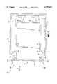
- FIG. 1is a sectional side view of a module and mainframe chassis according to a preferred embodiment of the invention.
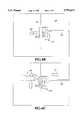
- FIG. 2is an enlarged sectional side view of an injector/ejector mechanism of the embodiment of FIG. 1.
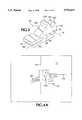
- FIG. 3is an isometric view of a lever component of the embodiment of FIG. 1.
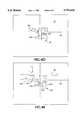
- FIGS. 4A-4Eare simplified enlarged sectional side views of an injector/ejector mechanism of the embodiment of FIG. 1 in various stages of operation.
- FIG. 1shows a modular electronic system 10 having a mainframe chassis 12 and a removable module 14.
- the chassisis in the shape of a box, with a front opening 16 and a rear wall 20 on which connectors 22 are mounted.
- upper and lower rails 24, 26are mounted to protrude toward each other to define the narrowest vertical dimension of the opening.
- a slide axis 30extends perpendicularly to the rear wall 20 and to the rails 26.
- the module 14includes a housing 32 having opposed major surfaces that face similar modules (not shown) mounted adjacently, or the side walls of the chassis.
- a rearwardly facing nose panel 34faces toward the rear wall 20 of the chassis, and has protruding connectors 36 that mate with connectors 22, and which are connected to electronic components (not shown) within the housing 32.
- An elongated face plate 40covers the front of the module housing, and is oriented normal to the slide axis 30.
- the face platehas upper and lower ends 42, 44 that respectively extend above and below the housing to form flanges that rest against the front edges of the rails 26 when installed.
- a pair of injector/ejector mechanisms 46, 48are connected to the face plate at the respective upper and lower ends 42, 44.
- the module 14slides into and out of the chassis 12 along the slide axis 30.
- the modulehas upper and lower fins 49 that slide within grooved guides 51 mounted to the upper and lower surfaces of the chassis chamber 50 to maintain the module in a vertical orientation and to align its connectors 36 with the chassis connectors 22.
- FIG. 2shows the lower injector/ejector mechanism 48, which is essentially a mirror image of mechanism 46, as reflected about a horizontal plane.
- Mechanism 48includes a frame 60 and a lever 62 pivotally mounted to the frame.
- the frameincludes a planar front panel 64 mounted against the front surface of the module face plate 40, covering the width of the face plate and a major portion of the length of the lower end flange 44.
- the panel 64defines a rectangular aperture 65 permitting passage of the lever, as will be discussed below.
- the framemay be screwed to the face plate, or fastened by any other conventional means.
- the framefurther includes a pair of rearwardly protruding stanchions 66 that extend through a rectangular hole 70 in the face plate 40 that is registered with the panel aperture 65.
- the stanchionsare spaced apart to define a gap that closely receives the lever 62, and are oriented in vertical planes parallel to the slide axis 30.
- a horizontal web panel 72spans between the upper edges of the stanchions, and extends from the front panel, through hole 70, to an intermediate point about midway between the front panel and the rearmost free ends of the stanchions.
- a pair of coaxial pivot holes 74penetrate the stanchions near their free ends, and are aligned on a pivot axis 76 oriented parallel to the chassis rail 26, and perpendicular to the major faces of the module.
- a pin 80is tightly received in the holes 74 to serve as a pivot axle for the lever 62.
- the pivot axis 76is positioned close to the upper edges of the stanchions (on the corresponding upper mechanism 46 close to the lower edges,) which extend parallel to the slide axis. This permits the pivot axis to be located as close as possible to the medial edge of the hole 70, while reserving as much space as possible on the faceplate between the holes 70 for functional components such as connectors, displays, and switches.
- the lever 62has a handle portion 82 that extends forward from the face plate for manipulation by a user, and a latch portion 84 that extends rearwardly through aperture 65 and hole 70, to the rear side of the face plate 40.
- the handle 82is a flat, wide planar member that is nearly parallel to a lever plane 86. In the preferred embodiment, the handle surfaces are offset laterally from the handle plane by about 6 degrees to provide effective manual contact during injection.
- the lever planeextends through the length of the handle to approximately intersect the pivot axis 76, on which a bore 90 is defined for receiving the pivot pin 80 as shown in FIG. 2. Thus, a force approximately normal to the plane of the handle will efficiently pivot the handle.
- the leverextends from a front handle end 92 to a rear latch end 94, and has a medial side 96 and a lateral side 100. As shown in FIG. 2, the lateral side faces away from the body of the module toward the chassis rail 26.
- a first tooth 102extends laterally (i.e. substantially perpendicular to the handle plane 86) for a limited distance.
- the bore 90as near the rear end of the lever as is structurally possible, and the rear end of the tooth being a flat plate substantially perpendicular to the handle plane 86, the first tooth extends substantially perpendicularly to the handle plane.
- upward movement of the handle 82will generate axial movement of the first tooth along the slide axis.
- a second tooth 104also extends laterally from the latch portion by a greater distance from the handle plane 86 than does the first tooth, so that the second tooth may engage an obstacle that the first tooth clears.
- the second toothis spaced apart from the first tooth, with a rear surface 106 of the second tooth facing the first tooth 102, and a front surface 110 of the first tooth facing the second tooth, defining a gap 112 therebetween.
- a wire torsion spring 114is positioned to receive the pin 80 within the bore defined by its coil, and has arms extending from the respective ends of the coil.
- a first spring arm 116presses upwardly into a pocket on the underside of web 72, and a second arm 120 presses downwardly into a pocket on the upper side of the lever.
- the leveris spring biased into the resting position shown in FIG. 2.
- the rail 26is an elongated bar that spans the width if the chassis, one on each of the upper and lower sides of the chassis opening 16.
- a spline 122extends from the middle of the surface of the rail that faces the opening and the opposed rail (in the illustrated lower rail 26 the spline extends upward from the upper surface.)
- Each splineruns the length of each rail.
- Each railhas a front surface 124 that faces the forward direction, and each spline 122 has a rear surface 126 that faces the rear of the chassis.
- the rear surface of the splineis spaced apart from the front edge of the slide groove member 51 by a distance of 0.140 inch (3.6 mm) in typical VXI applications. Therefore, the first tooth of the lever should have the illustrated thin profile so that it does not extend excessively toward the rear of the module when the lever is pivoted downward.
- FIGS. 4A-4Eshow the sequence of operation of the injector/ejector mechanism.
- FIG. 4Ashows the mechanism in a stable, resting state, in which the module 14 is uninstalled.
- the leveris spring biased laterally way from the chassis so that the handle 82 rests against the aperture 65 of the frame.
- the first tooth 102is retracted to an elevated level 130 that is above the level 132 of the tip of the spline 122. The ensures that the first tooth remains clear of the rail to avoid the damage that might occur if the lever were mispositioned.
- the second toothextends to a level at an intermediate point on the front surface 124 of the rail 26.
- FIG. 4Bshows the apparatus in a partially installed position, such as after a user has slid the module into the chassis as far as possible until the connectors at the rear of the module meet with substantial insertion resistance.
- the faceplate 40is spaced apart from the rail 26, and the lever has been pushed toward the middle of the instrument by contact of the second tooth 104 with the front surface 124 of the rail 26.
- the gap 112 between the teethis just wide enough so that the first tooth 102 is beyond the spline 122 when lever pivoting occurs, such that the first tooth does not limit the initial pivoting.
- FIG. 4Dshows the module fully installed, with the lever at rest.
- the rear surface 106 of the second tooth 104is biased by the spring to rest against the rail 26. This provides a uniform appearance when several modules are installed side by side, as the levers are all registered too the same rail. Also, if a user failed to fully install a module, but left it in the partially installed position shown in FIG. 4B, the different handle angle of the inadequately installed module would provide visual notice of the error.
- screws 134are screwed into tapped bores in the rail. Because the screws are not used to generate force to urge the module into place, the screws may be relatively small, requiring minimal face plate space that is required for functional components.
- FIG. 4EThe ejection process is shown in FIG. 4E. With screws 134 disengaged, handles 82 are pressed laterally away from each other. As with the step of FIG. 4C, this provides the benefits of balanced forces.
- the rear surface 106 of tooth 104presses against the fixed rail, extracting the module from the chassis.
- the rear surface 106is substantially radial to the pivot axis, avoiding wear and excessive force as discussed above, and is angularly offset from the handle plane 86 by 66 degrees. This offset should be as large as possible, preferably greater than 60 degrees.
- the lever and frame componentsare made of a rigid plastic such as 10% glass filled polycarbonate/ABS blend.
- the surface handle 82 exposed for manipulationis 0.59 inch (15 mm) wide and 0.59 inch (14 mm) long, providing a comfortable pad for fingertips to apply substantial force if needed.
- the handle surfaceshould be no smaller than 0.40 inch (10 mm) square.
- the first tooth 102extends radially 0.382 inch (9.7 mm) from the pivot axis, perpendicular to the handle plane, and the second tooth 104 extends radially 0.607 inch (15.4 mm) from the pivot axis, and 0.52 inch (13 mm) from the handle plane.
- the handlehas an angular range of motion of 60 degrees. From the installed position shown in FIG.
Landscapes
- Engineering & Computer Science (AREA)
- Microelectronics & Electronic Packaging (AREA)
- Mounting Of Printed Circuit Boards And The Like (AREA)
Abstract
Description
This is a continuation of application Ser. No. 08/707,788 filed Sep. 3, 1996 which is now abandoned.
The invention relates to modular electronic instrument systems, and more particularly to mechanisms for installing and removing modules from such systems.
Modular instrument systems permit a variety of different electronic instruments to be installed and interconnected in a single chassis. To create a customized system of test, measurement, and analysis equipment, such as for automated testing, a user selects the required modules, and installs them in a chassis that provides power, cooling, and functional electronic interconnection to the modules. Typically, the chassis is in the form of a cabinet with a large front aperture in which modules may be inserted side-by-side in the manner of books on a bookshelf. An example of such a system is a VXI (VME Extension for Instrumentation) test chassis using the VXIbus standard.
In typical VXI systems, the chassis or mainframe is a box with an open side, and with electronic connectors mounted to the interior of the box opposite the open side. Each module has a faceplate or front panel at one end, and one or more electronic connectors on the "nose" end opposite the face plate, so that the module connectors mate with the chassis connectors when the module is installed nose first into the chassis opening. As installed, the face plate is the only exposed portion of the module, and adjacent module face plates are flush to present a uniform appearance.
With the increasing number of connections required in a VXI module, substantial force is required to fully seat and remove modules. For instance, modules may have 3 or 4 DIN connections, each of which can require up to 20 pounds of insertion force. Consequently, mechanisms have been developed for providing additional leverage to drive the connectors home, and to extract them for removal of the module. This avoids the need for substantial force or impact against the module that may damage the equipment, or may move the chassis undesirably.
Existing lever mechanisms include levers that have handles extending from the face plate, and a claw extending toward a rail at the chassis opening. One tooth of the claw serves to engage the back side of the rail as the lever is actuated, to draw the module into connection with the chassis. A second tooth closer to the faceplate serves to push against the outer surface of the rail as the lever is pivoted in the opposite direction, pulling the module free of the connectors. However, existing levers are susceptible to damage if the lever is in an improper position in which the first tooth fails to clear the rail on insertion. Also, existing geometries that provide a first tooth short enough to clear the rail may not have a long enough tooth to fully draw in the module, requiring the use of panel screws to drive the module home. Existing levers may also present an unattractive appearance, as adjacent modules may have levers disposed at different angles after module installation, creating a nonuniform result. Other levers employ long, narrow handles that are stowed along the long edge of a module faceplate, and which are uncomfortable to users' fingers when large forces must be applied. Also, these levers can use valuable front panel space that may cause interference with a desired connection for input and output devices.
The embodiment disclosed herein overcomes these disadvantages by providing an injector/ejector mechanism with a lever pivotally connected to a module faceplate to pivot about a pivot axis. The lever has a handle extending away from the faceplate, and a latch portion extending away from the faceplate in a direction opposite the handle portion. The latch portion includes a first tooth and a second tooth, the first tooth being positioned farther from the faceplate than is the second tooth, The lever is movable between a first position in which the first tooth extends laterally from the pivot axis by a limited first amount, and a second position in which the first tooth extends laterally from the pivot axis by a greater second amount, and the lever is spring biased toward the first position.
FIG. 1 is a sectional side view of a module and mainframe chassis according to a preferred embodiment of the invention.
FIG. 2 is an enlarged sectional side view of an injector/ejector mechanism of the embodiment of FIG. 1.
FIG. 3 is an isometric view of a lever component of the embodiment of FIG. 1.
FIGS. 4A-4E are simplified enlarged sectional side views of an injector/ejector mechanism of the embodiment of FIG. 1 in various stages of operation.
FIG. 1 shows a modularelectronic system 10 having amainframe chassis 12 and aremovable module 14. The chassis is in the shape of a box, with a front opening 16 and arear wall 20 on whichconnectors 22 are mounted. At the upper and lower edges of theopening 16, upper andlower rails slide axis 30 extends perpendicularly to therear wall 20 and to therails 26.
Themodule 14 includes ahousing 32 having opposed major surfaces that face similar modules (not shown) mounted adjacently, or the side walls of the chassis. A rearwardly facingnose panel 34 faces toward therear wall 20 of the chassis, and has protrudingconnectors 36 that mate withconnectors 22, and which are connected to electronic components (not shown) within thehousing 32. Anelongated face plate 40 covers the front of the module housing, and is oriented normal to theslide axis 30. The face plate has upper andlower ends rails 26 when installed. A pair of injector/ejector mechanisms lower ends
Themodule 14 slides into and out of thechassis 12 along theslide axis 30. The module has upper andlower fins 49 that slide withingrooved guides 51 mounted to the upper and lower surfaces of thechassis chamber 50 to maintain the module in a vertical orientation and to align itsconnectors 36 with thechassis connectors 22.
FIG. 2 shows the lower injector/ejector mechanism 48, which is essentially a mirror image ofmechanism 46, as reflected about a horizontal plane.Mechanism 48 includes aframe 60 and alever 62 pivotally mounted to the frame.
The frame includes a planarfront panel 64 mounted against the front surface of themodule face plate 40, covering the width of the face plate and a major portion of the length of thelower end flange 44. Thepanel 64 defines arectangular aperture 65 permitting passage of the lever, as will be discussed below. The frame may be screwed to the face plate, or fastened by any other conventional means.
The frame further includes a pair of rearwardly protrudingstanchions 66 that extend through arectangular hole 70 in theface plate 40 that is registered with thepanel aperture 65. The stanchions are spaced apart to define a gap that closely receives thelever 62, and are oriented in vertical planes parallel to theslide axis 30. Ahorizontal web panel 72 spans between the upper edges of the stanchions, and extends from the front panel, throughhole 70, to an intermediate point about midway between the front panel and the rearmost free ends of the stanchions. A pair ofcoaxial pivot holes 74 penetrate the stanchions near their free ends, and are aligned on apivot axis 76 oriented parallel to thechassis rail 26, and perpendicular to the major faces of the module.
Apin 80 is tightly received in theholes 74 to serve as a pivot axle for thelever 62. Thepivot axis 76 is positioned close to the upper edges of the stanchions (on the correspondingupper mechanism 46 close to the lower edges,) which extend parallel to the slide axis. This permits the pivot axis to be located as close as possible to the medial edge of thehole 70, while reserving as much space as possible on the faceplate between theholes 70 for functional components such as connectors, displays, and switches.
As shown in FIG. 3, thelever 62 has ahandle portion 82 that extends forward from the face plate for manipulation by a user, and alatch portion 84 that extends rearwardly throughaperture 65 andhole 70, to the rear side of theface plate 40. Thehandle 82 is a flat, wide planar member that is nearly parallel to alever plane 86. In the preferred embodiment, the handle surfaces are offset laterally from the handle plane by about 6 degrees to provide effective manual contact during injection. The lever plane extends through the length of the handle to approximately intersect thepivot axis 76, on which abore 90 is defined for receiving thepivot pin 80 as shown in FIG. 2. Thus, a force approximately normal to the plane of the handle will efficiently pivot the handle.
The lever extends from afront handle end 92 to arear latch end 94, and has amedial side 96 and alateral side 100. As shown in FIG. 2, the lateral side faces away from the body of the module toward thechassis rail 26. On thelateral side 100 of thelatch portion 84 at therear end 94, afirst tooth 102 extends laterally (i.e. substantially perpendicular to the handle plane 86) for a limited distance. With thebore 90 as near the rear end of the lever as is structurally possible, and the rear end of the tooth being a flat plate substantially perpendicular to thehandle plane 86, the first tooth extends substantially perpendicularly to the handle plane. Thus, upward movement of thehandle 82 will generate axial movement of the first tooth along the slide axis.
Asecond tooth 104 also extends laterally from the latch portion by a greater distance from thehandle plane 86 than does the first tooth, so that the second tooth may engage an obstacle that the first tooth clears. The second tooth is spaced apart from the first tooth, with arear surface 106 of the second tooth facing thefirst tooth 102, and afront surface 110 of the first tooth facing the second tooth, defining agap 112 therebetween.
As shown in FIG. 2, awire torsion spring 114 is positioned to receive thepin 80 within the bore defined by its coil, and has arms extending from the respective ends of the coil. Afirst spring arm 116 presses upwardly into a pocket on the underside ofweb 72, and asecond arm 120 presses downwardly into a pocket on the upper side of the lever. Thus, the lever is spring biased into the resting position shown in FIG. 2.
Therail 26 is an elongated bar that spans the width if the chassis, one on each of the upper and lower sides of thechassis opening 16. Aspline 122 extends from the middle of the surface of the rail that faces the opening and the opposed rail (in the illustratedlower rail 26 the spline extends upward from the upper surface.) Each spline runs the length of each rail. Each rail has afront surface 124 that faces the forward direction, and eachspline 122 has arear surface 126 that faces the rear of the chassis. The rear surface of the spline is spaced apart from the front edge of theslide groove member 51 by a distance of 0.140 inch (3.6 mm) in typical VXI applications. Therefore, the first tooth of the lever should have the illustrated thin profile so that it does not extend excessively toward the rear of the module when the lever is pivoted downward.
FIGS. 4A-4E show the sequence of operation of the injector/ejector mechanism. FIG. 4A shows the mechanism in a stable, resting state, in which themodule 14 is uninstalled. As similarly shown in FIG. 2, the lever is spring biased laterally way from the chassis so that thehandle 82 rests against theaperture 65 of the frame. In this position, thefirst tooth 102 is retracted to anelevated level 130 that is above thelevel 132 of the tip of thespline 122. The ensures that the first tooth remains clear of the rail to avoid the damage that might occur if the lever were mispositioned. The second tooth extends to a level at an intermediate point on thefront surface 124 of therail 26.
FIG. 4B shows the apparatus in a partially installed position, such as after a user has slid the module into the chassis as far as possible until the connectors at the rear of the module meet with substantial insertion resistance. Thefaceplate 40 is spaced apart from therail 26, and the lever has been pushed toward the middle of the instrument by contact of thesecond tooth 104 with thefront surface 124 of therail 26. Thegap 112 between the teeth is just wide enough so that thefirst tooth 102 is beyond thespline 122 when lever pivoting occurs, such that the first tooth does not limit the initial pivoting.
In FIG. 4C, a user is pressing medially on both lever handles 82 to fully mate the connectors. Theface plate 40 rests against therail 26. Because of the relatively large distance between the pivot axis and the point at which force is applied to the handle, as compared to the radial distance between the pivot axis and the point of contact at the tip of the first tooth, substantial leverage is attained. Because thefront surface 110 of the first tooth is nearly radial to the pivot axis, there is very little camming or sliding effect that might increase wear or require excessive force by the user. Because the first tooth extends nearly perpendicularly to the handle, a medial motion of the handle directly toward the opposite handle in a "pinching" motion generates a force closely aligned along the slide axis, making efficient use of the user's force. This also provides that the applied forces are equal and opposed, so that the chassis is not moved in response to the force.
FIG. 4D shows the module fully installed, with the lever at rest. Therear surface 106 of thesecond tooth 104 is biased by the spring to rest against therail 26. This provides a uniform appearance when several modules are installed side by side, as the levers are all registered too the same rail. Also, if a user failed to fully install a module, but left it in the partially installed position shown in FIG. 4B, the different handle angle of the inadequately installed module would provide visual notice of the error. To prevent inadvertent disconnection of the module, screws 134 are screwed into tapped bores in the rail. Because the screws are not used to generate force to urge the module into place, the screws may be relatively small, requiring minimal face plate space that is required for functional components.
The ejection process is shown in FIG. 4E. Withscrews 134 disengaged, handles 82 are pressed laterally away from each other. As with the step of FIG. 4C, this provides the benefits of balanced forces. Therear surface 106 oftooth 104 presses against the fixed rail, extracting the module from the chassis. Therear surface 106 is substantially radial to the pivot axis, avoiding wear and excessive force as discussed above, and is angularly offset from thehandle plane 86 by 66 degrees. This offset should be as large as possible, preferably greater than 60 degrees.
In the preferred embodiment the lever and frame components are made of a rigid plastic such as 10% glass filled polycarbonate/ABS blend. The surface handle 82 exposed for manipulation is 0.59 inch (15 mm) wide and 0.59 inch (14 mm) long, providing a comfortable pad for fingertips to apply substantial force if needed. Preferably the handle surface should be no smaller than 0.40 inch (10 mm) square. Thefirst tooth 102 extends radially 0.382 inch (9.7 mm) from the pivot axis, perpendicular to the handle plane, and thesecond tooth 104 extends radially 0.607 inch (15.4 mm) from the pivot axis, and 0.52 inch (13 mm) from the handle plane. The handle has an angular range of motion of 60 degrees. From the installed position shown in FIG. 4D, there is a 17 degree range of motion for injection, and a 43 degree motion for ejection. When in the uninstalled position, the first tooth should clear the rail spline by about 0.04 inch (1 mm), and when leveraging the module into place, should overlap the spline by 0.94 inch (2.4 mm).
While the disclosure is made in terms of a preferred embodiment, the invention is not intended to be so limited.
Claims (17)
1. A modular electronic instrument system comprising:
a mainframe having at least top, bottom and rear members and an open frontal area, the mainframe defining a chamber having an interior surface;
a plurality of module slots extending into the mainframe chamber from the open frontal area to the rear member;
a plurality of electronic connectors connected to the interior surface;
the module slots of the mainframe including a rigid rail;
a plurality of electronic modules adapted for insertion into respective module slots in electrical communication with the mainframe connectors, each module including a housing containing an electronic component and having a face plate having a front side facing away from the housing, and a rear side facing the connectors;
each module having a spring-biased pivoting lever connected to the face plate and registered with the rail when the module is installed in the mainframe;
each lever being pivotally mounted to pivot about a pivot axis positioned on the rear side of the face plate, and having a handle extending from the front side of the face plate;
each lever having a pair of laterally extending teeth defining a gap adapted for receiving at least a portion of the rail when the module is fully installed;
the lever being movable between a first medial position and a second lateral position, at least a portion of a first one of the teeth being positioned rearwardly of the pivot axis when the lever is in the lateral position; and
the lever being spring biased toward the lateral position such that the first tooth is maintained clear of the rail during installation of the module.
2. The apparatus of claim 1 wherein the lever includes a handle extending substantially perpendicular to the plane of the face plate when the lever is in the medial position.
3. The apparatus of claim 1 wherein the first tooth extends substantially perpendicular to a plane containing the handle and the pivot axis.
4. The apparatus of claim 1 wherein the first tooth has an injector surface facing the gap, and wherein the injector surface is substantially radial to the pivot axis.
5. The apparatus of claim 1 wherein the second tooth is biased against the rail when the module is installed in the mainframe.
6. The apparatus of claim 1 wherein the levers are positioned on opposite ends of the faceplate, and centered on a median line of the faceplate.
7. The apparatus of claim 1 wherein the handle includes a planar surface oriented substantially normal to its direction of pivoting movement, such that force may be distributed across the surface to operate the lever.
8. The apparatus of claim 7 wherein the handle has a width measured along a line parallel to the pivot axis greater than 10 mm, such that the handle may be operated comfortably by a fingertip.
9. An injector/ejector mechanism for facilitating the insertion and removal of an electronic module from a mainframe housing having a fixed frame element, the module having a faceplate with an external surface, and being slidable within a slot along a slide axis perpendicular to the faceplate within the mainframe, the mechanism comprising:
a lever pivotally connected to the faceplate to pivot about a pivot axis;
the lever having a handle portion extending from the faceplate away from the external surface;
the lever having a latch portion extending away from the faceplate in a direction opposite the handle portion;
the latch portion including a first tooth and a second tooth, the teeth extending laterally relative to the slide axis and being spaced apart to define a gap;
the first tooth being positioned farther from the faceplate than is the second tooth;
the lever being movable between a first position in which the first tooth extends laterally from the pivot axis by a limited first amount, and a second position in which the first tooth extends laterally from the pivot axis by a greater second amount, such that the first tooth is clear of the frame element to facilitate insertion when the lever is in the first position, and such that the first tooth engages the frame element when the lever is moved to the second position, whereby the module may be leveraged into the mainframe by biasing the lever toward the second position; and
the lever being spring biased to the first position.
10. The apparatus of claim 9 wherein the second tooth extends laterally by a third amount greater than first amount when the lever is in the first position, such that second tooth engages frame element upon insertion of the module into the mainframe.
11. The apparatus of claim 9 wherein the second tooth is positioned closer to the faceplate than is the pivot axis, such that actuation of the handle in the direction the teeth extend causes the second tooth to move away from the face plate, whereby ejection of the module is facilitated.
12. The apparatus of claim 9 wherein the first tooth is positioned farther from the face plate than is the pivot axis when the lever is in the first position, such that movement of the handle in the direction away from the direction the teeth extend causes the first tooth to extend to the greater second amount.
13. The apparatus of claim 9 wherein the handle extends substantially perpendicularly from the faceplate when in the second position.
14. The apparatus of claim 9 wherein the handle includes a planar element extending substantially radially from the pivot axis, such that a force normal to the planar element will tend to pivot the lever.
15. The apparatus of claim 9 wherein the planar element of the handle has a width of at least 1.0 cm, such that substantial force may be applied while distributed over a substantial area of a user's fingertip.
16. The apparatus of claim 9 including a spring connected to the faceplate and the lever.
17. The apparatus of claim 9 wherein the pivot axis is spaced apart from the faceplate by a greater distance than the width of the gap between the first and second teeth.
Priority Applications (1)
| Application Number | Priority Date | Filing Date | Title |
|---|---|---|---|
| US08/953,491US5793614A (en) | 1996-09-03 | 1997-10-17 | Injector/ejector for electronic module housing |
Applications Claiming Priority (2)
| Application Number | Priority Date | Filing Date | Title |
|---|---|---|---|
| US70778896A | 1996-09-03 | 1996-09-03 | |
| US08/953,491US5793614A (en) | 1996-09-03 | 1997-10-17 | Injector/ejector for electronic module housing |
Related Parent Applications (1)
| Application Number | Title | Priority Date | Filing Date |
|---|---|---|---|
| US70778896AContinuation | 1996-09-03 | 1996-09-03 |
Publications (1)
| Publication Number | Publication Date |
|---|---|
| US5793614Atrue US5793614A (en) | 1998-08-11 |
Family
ID=24843171
Family Applications (1)
| Application Number | Title | Priority Date | Filing Date |
|---|---|---|---|
| US08/953,491Expired - Fee RelatedUS5793614A (en) | 1996-09-03 | 1997-10-17 | Injector/ejector for electronic module housing |
Country Status (1)
| Country | Link |
|---|---|
| US (1) | US5793614A (en) |
Cited By (113)
| Publication number | Priority date | Publication date | Assignee | Title |
|---|---|---|---|---|
| US5928016A (en)* | 1997-10-16 | 1999-07-27 | International Business Machines Corporation | Direct access storage device housing and tray design |
| US5933322A (en)* | 1996-10-23 | 1999-08-03 | Compaq Computer Corporation | Computer docking station with integral base security system |
| US5980281A (en)* | 1998-02-11 | 1999-11-09 | International Business Machines Corporation | Mechanism to assist in insertion or removal of PCI cards |
| US6022327A (en)* | 1998-05-04 | 2000-02-08 | Chang; Henry Ping | Facial steamer machine with detachable function units |
| WO2000022488A1 (en)* | 1998-10-09 | 2000-04-20 | Primex Aerospace Company | Aircraft data management system |
| US6056574A (en)* | 1998-09-29 | 2000-05-02 | The Whitaker Corporation | Retention assembly with cap for processor modules |
| US6134115A (en)* | 1999-04-13 | 2000-10-17 | Dell Usa, L.P. | Apparatus for securing a removable component in a computer system |
| US6147872A (en)* | 1999-02-08 | 2000-11-14 | Excel Switching Corporation | Injector/ejector machanism for printed circuit cards |
| US6247944B1 (en)* | 1998-06-15 | 2001-06-19 | Compaq Computer Corporation | Slide-activated, spring-loaded ejector for hot-pluggable disk drive carrier |
| US6259607B1 (en)* | 1999-08-19 | 2001-07-10 | Compal Electronics, Inc. | Ejector device for a mobile module |
| US6267614B1 (en)* | 2000-02-03 | 2001-07-31 | International Business Machines Corporation | Low profile/high leverage electronic computer book latching system |
| US6285548B1 (en) | 2000-08-18 | 2001-09-04 | Quantum Bridge Communications, Inc. | Face plate for a chassis for high frequency components |
| US6301099B1 (en)* | 1998-04-14 | 2001-10-09 | Compaq Computer Corporation | Computer having option card module latching and drive bay pivot structures |
| US6317329B1 (en)* | 1998-11-13 | 2001-11-13 | Hewlett-Packard Company | Data storage module alignment system and method |
| US6351786B2 (en)* | 1998-08-24 | 2002-02-26 | Racal Instr Inc | VXI backplane system improvements and methods |
| US6381146B1 (en)* | 2000-09-28 | 2002-04-30 | Hewlett-Packard Company | Module removal system |
| US6385036B1 (en)* | 1999-09-10 | 2002-05-07 | Robert C. Chien | Screwless computer case assembly |
| US6413122B2 (en)* | 1999-12-22 | 2002-07-02 | Nec Corporation | Wrong insertion preventing mechanism |
| US20020089821A1 (en)* | 2000-11-10 | 2002-07-11 | Acard Technology Corporation | Automated disk-ejection apparatus and disk array having the same |
| US6442034B1 (en)* | 1999-07-12 | 2002-08-27 | Alstom | Front face of an electronics card and an electronics card |
| US20030030993A1 (en)* | 2001-08-10 | 2003-02-13 | Kitchen James Robert | Module ejection mechanism |
| US20030035271A1 (en)* | 2001-08-03 | 2003-02-20 | Stephane Lelong | Housing for a computer sub-assembly, a keeper for use with a housing for a computer sub-assembly and a support member for a computer sub-assembly |
| GB2379092A (en)* | 2001-08-10 | 2003-02-26 | Sun Microsystems Inc | Ejection/injection lever for computer module |
| US6556432B2 (en)* | 2000-12-28 | 2003-04-29 | Hon Hai Precision Ind. Co., Ltd. | Drive bracket having a pivotable fastener |
| US6585212B2 (en)* | 2001-08-20 | 2003-07-01 | Jeffrey D. Carnevali | Quick release electronics platform |
| US20030145705A1 (en)* | 2002-02-04 | 2003-08-07 | Blaine Miller | Fence |
| US20030171016A1 (en)* | 2002-03-06 | 2003-09-11 | Bright Edward John | Transceiver module assembly ejector mechanism |
| US20030214790A1 (en)* | 2002-05-10 | 2003-11-20 | Hanson George E. | Integrated CRU latch |
| US6685489B1 (en)* | 2002-10-24 | 2004-02-03 | Hewlett-Packard Development Company, L.P. | Circuit board leverage mechanism |
| US6693798B1 (en) | 2003-05-09 | 2004-02-17 | Hewlett-Packard Development Company, Lp. | Electronic unit enclosure and method |
| US20040080901A1 (en)* | 2002-10-25 | 2004-04-29 | Chen Li Ping | Computer enclosure having engaging device |
| US20040117946A1 (en)* | 2002-12-20 | 2004-06-24 | Kuo-Chih Lin | Latch for removing a cover from a base |
| US20040174686A1 (en)* | 2003-03-05 | 2004-09-09 | Rubenstein Brandon A. | Device and method for circuit board insertion and removal |
| US6796817B2 (en)* | 2001-01-09 | 2004-09-28 | Sun Microsystems, Inc. | Circuit board ejector mechanism including flexible coupling |
| US6802727B2 (en)* | 2001-12-06 | 2004-10-12 | International Business Machines Corporation | Apparatus for and method of connecting connectors |
| US20040219811A1 (en)* | 2003-04-29 | 2004-11-04 | International Business Machines Corporation | Apparatus for positioning an electrical assembly within a housing |
| US20040264146A1 (en)* | 2003-06-27 | 2004-12-30 | Kerrigan Brian Michael | Handling system for use with a blade in a blade server system |
| US20050014403A1 (en)* | 2003-07-18 | 2005-01-20 | Schroff Gmbh | Plug-in module for plugging in and/or pulling out of a module rack |
| US6850415B2 (en)* | 1998-12-31 | 2005-02-01 | Honeywell International Inc. | Methods and apparatus for circuit integration |
| US20050141191A1 (en)* | 2003-12-30 | 2005-06-30 | Long Brian J. | Electrically isolated semi-locking hinge for cooling system |
| US20050148223A1 (en)* | 2004-01-06 | 2005-07-07 | Shirk Michael E. | Release mechanism for transceiver module assembly |
| US20050231923A1 (en)* | 2004-04-17 | 2005-10-20 | Hon Hai Precision Industry Co., Ltd. | Ejector for motherboard |
| US20050257352A1 (en)* | 2003-08-07 | 2005-11-24 | Carnevali Jeffrey D | Quick draw cradle apparatus |
| US20060026807A1 (en)* | 2003-08-07 | 2006-02-09 | Carnevali Jeffrey D | Quick release mounting apparatus |
| US20060039106A1 (en)* | 2004-08-20 | 2006-02-23 | Fujitsu Limited | Ejector, unit and electronic apparatus having the same |
| US20060067063A1 (en)* | 2004-09-30 | 2006-03-30 | Stahl Douglas L | Insertion and ejection mechanisms for modular boards and cards |
| US20060094276A1 (en)* | 2004-11-01 | 2006-05-04 | Tekelec | Methods and systems for controlling operation of a module |
| US7070431B1 (en)* | 2005-03-02 | 2006-07-04 | Hewlett-Packard Development Company, L.P. | Method and apparatus for ejecting a riser card |
| US20060161936A1 (en)* | 2005-01-18 | 2006-07-20 | Spectra Logic Corporation | Combination storage extracting and biasing system |
| US7083447B2 (en) | 2004-02-16 | 2006-08-01 | Dspace Digital Signal Processing And Control Engineering Gmbh | Printed circuit board module and disconnect bow |
| US20060264077A1 (en)* | 2003-07-25 | 2006-11-23 | Utstarcom Korea Limited | Injector/ejector and shelf structure grounded to card frame ground |
| US20060285306A1 (en)* | 2005-05-24 | 2006-12-21 | Carnevali Jeffrey D | Secure universal mounting apparatus |
| US20070022582A1 (en)* | 2005-07-28 | 2007-02-01 | Carnevali Jeffrey D | Thumb release mounting apparatus |
| US20070022583A1 (en)* | 2005-07-28 | 2007-02-01 | Carnevali Jeffrey D | Thumb release mounting apparatus |
| US7188400B1 (en) | 2002-02-28 | 2007-03-13 | Garmin International, Inc. | Method for mounting units for an avionic display |
| US20070058354A1 (en)* | 2005-09-13 | 2007-03-15 | International Business Machines Corporation | System and method for insertion, retention and extraction of a card-let printed circuit board, without protective hardware into and from a motherboard |
| US20070076366A1 (en)* | 2005-07-15 | 2007-04-05 | Fujitsu Limited | Loadable/unloadable adapter for substrate |
| US20080045051A1 (en)* | 2006-08-18 | 2008-02-21 | Fujitsu Limited | PIU plug-in/plug-off mechanism for electronic apparatus |
| US7349228B1 (en)* | 2003-11-24 | 2008-03-25 | Extreme Networks | Ejector assembly for rack-mounted computing devices |
| US7417866B1 (en)* | 2002-02-28 | 2008-08-26 | Garmin International, Inc. | Electronic equipment module mounting apparatus and method |
| US20080203263A1 (en)* | 2007-02-23 | 2008-08-28 | Carnevali Jeffrey D | Adaptive mounting structure |
| US20080296449A1 (en)* | 2007-05-31 | 2008-12-04 | Carnevali Jeffrey D | Quick release electronics platform |
| US20080296821A1 (en)* | 2007-05-31 | 2008-12-04 | Carnevali Jeffrey D | Quick release electronics platform |
| US20090212189A1 (en)* | 2007-05-31 | 2009-08-27 | Carnevali Jeffrey D | Quick release electronics platform |
| US20100033927A1 (en)* | 2008-08-05 | 2010-02-11 | Japan Aviation Electronics Industry, Limited | Eject mechanism and electrical apparatus comprising the same |
| DE102008056749B3 (en)* | 2008-11-11 | 2010-04-01 | Fujitsu Siemens Computers Gmbh | Insertion module for use in laptop computer, has microcontroller connected with equipment connections and equipped to select one of host connections for controlling mass storage device |
| DE102004006503B4 (en)* | 2004-02-10 | 2011-07-21 | Fujitsu Siemens Computers GmbH, 80807 | shutter |
| US20110176271A1 (en)* | 2010-01-16 | 2011-07-21 | Hong Fu Jin Precision Industry (Shenzhen) Co., Ltd | Computer system with cooling airflow passages |
| US7995347B1 (en)* | 2005-06-01 | 2011-08-09 | Juniper Networks, Inc. | Configurable chassis shelf |
| US20110297628A1 (en)* | 2010-06-08 | 2011-12-08 | Hon Hai Precision Industry Co., Ltd. | Server rack assembly |
| US20110299257A1 (en)* | 2010-06-04 | 2011-12-08 | Fujitsu Limited | Insertional buffering structure of substrate unit |
| US20120188740A1 (en)* | 2011-01-21 | 2012-07-26 | Wistron Corporation | Electronic device |
| US20120275104A1 (en)* | 2011-04-26 | 2012-11-01 | Dell Products L.P. | Modular component chassis coupling system |
| US20120275129A1 (en)* | 2011-04-28 | 2012-11-01 | Hon Hai Precision Industry Co., Ltd. | Mounting apparatus for expansion card |
| US20130084127A1 (en)* | 2011-09-30 | 2013-04-04 | Mao-Yuan Lo | Apparatus with a handle having a release mechanism |
| US20130100604A1 (en)* | 2011-10-25 | 2013-04-25 | Dell Products L.P. | Suspended Hard Disk Drive System for Portable Computers |
| US20140198434A1 (en)* | 2013-01-15 | 2014-07-17 | Wistron Corporation | Fixing mechanism and related electronic device |
| US20150014912A1 (en)* | 2013-07-02 | 2015-01-15 | Atlas Sound Lp | Electronic module installation tools for electronic racks |
| US20150181743A1 (en)* | 2013-12-23 | 2015-06-25 | Brocade Communications Systems, Inc. | Ejector and cable management system and method |
| US20150189774A1 (en)* | 2013-12-30 | 2015-07-02 | Motorola Mobility Llc | Method and apparatus for operating a tray mechanism |
| EP2749159A4 (en)* | 2012-04-25 | 2016-03-30 | Ericsson Telefon Ab L M | An ejector assembly |
| EP3035781A1 (en)* | 2014-12-18 | 2016-06-22 | Alcatel Lucent | Angled Latch |
| US20160291644A1 (en)* | 2015-03-30 | 2016-10-06 | Seagate Technology Llc | Base deck with carrier features |
| US9535457B1 (en)* | 2014-03-24 | 2017-01-03 | Xplore Technologies Corp. | Docking station with improved latching mechanism |
| US20170280579A1 (en)* | 2016-03-25 | 2017-09-28 | Chiun Mai Communication Systems, Inc. | Chip card securing assembly and electronic device applying the same |
| US9859654B1 (en)* | 2016-10-25 | 2018-01-02 | Eaton Corporation | Ejector mechanism for electrical assembly |
| US20180046230A1 (en)* | 2015-02-20 | 2018-02-15 | Hewlett Packard Enterprise Development Lp | Tool-less multipoint latching mechanism |
| US20180092234A1 (en)* | 2014-04-10 | 2018-03-29 | Ting-Jui Wang | Quick release connecting device |
| US9933109B2 (en) | 2015-06-03 | 2018-04-03 | Dgm Enterprises Llc | Vibration resistant equipment mount |
| US10129997B2 (en)* | 2017-01-05 | 2018-11-13 | Oracle International Corporation | Guide assembly for proper electrical blind mating of a module in an enclosure |
| US10178791B1 (en) | 2017-09-23 | 2019-01-08 | Facebook, Inc. | Apparatus, system, and method for securing computing components to printed circuit boards |
| US20190075668A1 (en)* | 2017-09-06 | 2019-03-07 | Facebook, Inc. | Apparatus, system, and method for securing hard drives in a storage chassis |
| US20190082553A1 (en)* | 2016-10-11 | 2019-03-14 | Abb Schweiz Ag | Power connector for electronic equipment supported by a rack assembly |
| US10240615B1 (en) | 2017-09-23 | 2019-03-26 | Facebook, Inc. | Apparatus, system, and method for dampening vibrations generated by exhaust fans |
| US10330251B2 (en) | 2016-11-24 | 2019-06-25 | Jeffrey D. Carnevali | Finger grip mounting apparatus |
| US10349554B2 (en) | 2017-08-29 | 2019-07-09 | Facebook, Inc. | Apparatus, system, and method for directing air in a storage-system chassis |
| US10372360B2 (en) | 2017-09-01 | 2019-08-06 | Facebook, Inc. | Apparatus, system, and method for reconfigurable media-agnostic storage |
| US10412852B1 (en)* | 2017-04-17 | 2019-09-10 | EMC IP Holding Company LLC | Multi-piece storage shuttle |
| US10429911B2 (en) | 2017-09-07 | 2019-10-01 | Facebook, Inc. | Apparatus, system, and method for detecting device types of storage devices |
| US10558248B2 (en) | 2017-09-09 | 2020-02-11 | Facebook, Inc. | Apparatus, system, and method for indicating the status of and securing hard drives |
| US10588238B2 (en) | 2017-09-18 | 2020-03-10 | Facebook, Inc. | Apparatus, system, and method for partitioning a storage-system chassis |
| US10622761B1 (en)* | 2018-08-30 | 2020-04-14 | Facebook, Inc. | Moveable floating connector |
| US10687435B2 (en) | 2017-08-28 | 2020-06-16 | Facebook, Inc. | Apparatus, system, and method for enabling multiple storage-system configurations |
| US10736228B2 (en) | 2017-08-31 | 2020-08-04 | Facebook, Inc. | Removeable drive-plane apparatus, system, and method |
| US10757831B2 (en) | 2017-09-26 | 2020-08-25 | Facebook, Inc. | Apparatus, system, and method for reconfiguring air flow through a chassis |
| US20220061181A1 (en)* | 2020-08-21 | 2022-02-24 | National Instruments Corporation | High-Speed Performance Electrical Connector for Modular Electronics Systems |
| US11304325B2 (en)* | 2018-08-10 | 2022-04-12 | Aisin Corporation | Case structure |
| US11317532B2 (en)* | 2020-07-23 | 2022-04-26 | Portwell Inc. | Labor-saving mainboard withdrawing stucture for electronic devices |
| US20230037056A1 (en)* | 2021-08-02 | 2023-02-02 | Dtech Precision Industries Co., Ltd. | Welding structure capable of rotational movement and welding method for the same |
| US11719026B2 (en)* | 2019-12-27 | 2023-08-08 | Quanta Computer Inc. | Integrated latch mechanism for securing rackmount equipment in a chassis |
| US20230334270A1 (en)* | 2022-04-14 | 2023-10-19 | Dell Products L.P. | System, device, and method for securing removable cards with varying mechanical geometry |
| US20240044529A1 (en)* | 2022-08-05 | 2024-02-08 | Delta Electronics, Inc. | Cooling distribution unit and assembling/disassembling method thereof |
| US20240268055A1 (en)* | 2021-11-08 | 2024-08-08 | Suzhou Metabrain Intelligent Technology Co., Ltd. | Chassis with chassis lock, and opening/closing method |
Citations (6)
| Publication number | Priority date | Publication date | Assignee | Title |
|---|---|---|---|---|
| US4996631A (en)* | 1989-10-30 | 1991-02-26 | Canoga Industries, Inc. | Injector/ejector system for rack mounted plug-in modules with front panels |
| US5139430A (en)* | 1990-06-28 | 1992-08-18 | Digital Equipment Corporation | PCB insertion/ejection lever mechanism |
| US5222897A (en)* | 1992-04-01 | 1993-06-29 | Emc Corporation | Circuit board inserter/ejector system |
| US5293303A (en)* | 1991-12-11 | 1994-03-08 | Bicc Public Limited Company | Circuit board injector/ejector device for a circuit board enclosure |
| US5309325A (en)* | 1993-02-19 | 1994-05-03 | Eg&G Birtcher, Inc. | Locking circuit board injector/extractor |
| US5542854A (en)* | 1995-01-17 | 1996-08-06 | Molex Incorporated | Edge card connector with alignment means |
- 1997
- 1997-10-17USUS08/953,491patent/US5793614A/ennot_activeExpired - Fee Related
Patent Citations (6)
| Publication number | Priority date | Publication date | Assignee | Title |
|---|---|---|---|---|
| US4996631A (en)* | 1989-10-30 | 1991-02-26 | Canoga Industries, Inc. | Injector/ejector system for rack mounted plug-in modules with front panels |
| US5139430A (en)* | 1990-06-28 | 1992-08-18 | Digital Equipment Corporation | PCB insertion/ejection lever mechanism |
| US5293303A (en)* | 1991-12-11 | 1994-03-08 | Bicc Public Limited Company | Circuit board injector/ejector device for a circuit board enclosure |
| US5222897A (en)* | 1992-04-01 | 1993-06-29 | Emc Corporation | Circuit board inserter/ejector system |
| US5309325A (en)* | 1993-02-19 | 1994-05-03 | Eg&G Birtcher, Inc. | Locking circuit board injector/extractor |
| US5542854A (en)* | 1995-01-17 | 1996-08-06 | Molex Incorporated | Edge card connector with alignment means |
Cited By (175)
| Publication number | Priority date | Publication date | Assignee | Title |
|---|---|---|---|---|
| US5933322A (en)* | 1996-10-23 | 1999-08-03 | Compaq Computer Corporation | Computer docking station with integral base security system |
| US5928016A (en)* | 1997-10-16 | 1999-07-27 | International Business Machines Corporation | Direct access storage device housing and tray design |
| US5980281A (en)* | 1998-02-11 | 1999-11-09 | International Business Machines Corporation | Mechanism to assist in insertion or removal of PCI cards |
| US6661654B2 (en) | 1998-04-14 | 2003-12-09 | Hewlett-Packard Development Company, L.P. | Computer having option card module latching and drive bay pivot structures |
| US6301099B1 (en)* | 1998-04-14 | 2001-10-09 | Compaq Computer Corporation | Computer having option card module latching and drive bay pivot structures |
| US6022327A (en)* | 1998-05-04 | 2000-02-08 | Chang; Henry Ping | Facial steamer machine with detachable function units |
| US6247944B1 (en)* | 1998-06-15 | 2001-06-19 | Compaq Computer Corporation | Slide-activated, spring-loaded ejector for hot-pluggable disk drive carrier |
| US6302714B1 (en) | 1998-06-15 | 2001-10-16 | Compaq Computer Corporation | Slide-activated, spring-loaded ejector for hot-pluggable disk drive carrier |
| US6351786B2 (en)* | 1998-08-24 | 2002-02-26 | Racal Instr Inc | VXI backplane system improvements and methods |
| US6056574A (en)* | 1998-09-29 | 2000-05-02 | The Whitaker Corporation | Retention assembly with cap for processor modules |
| US20030208764A1 (en)* | 1998-10-09 | 2003-11-06 | Galipeau Steven R. | Aircraft data management system |
| US6249913B1 (en) | 1998-10-09 | 2001-06-19 | General Dynamics Ots (Aerospace), Inc. | Aircraft data management system |
| WO2000022488A1 (en)* | 1998-10-09 | 2000-04-20 | Primex Aerospace Company | Aircraft data management system |
| US6317329B1 (en)* | 1998-11-13 | 2001-11-13 | Hewlett-Packard Company | Data storage module alignment system and method |
| US6850415B2 (en)* | 1998-12-31 | 2005-02-01 | Honeywell International Inc. | Methods and apparatus for circuit integration |
| US6147872A (en)* | 1999-02-08 | 2000-11-14 | Excel Switching Corporation | Injector/ejector machanism for printed circuit cards |
| US6134115A (en)* | 1999-04-13 | 2000-10-17 | Dell Usa, L.P. | Apparatus for securing a removable component in a computer system |
| US6442034B1 (en)* | 1999-07-12 | 2002-08-27 | Alstom | Front face of an electronics card and an electronics card |
| US6259607B1 (en)* | 1999-08-19 | 2001-07-10 | Compal Electronics, Inc. | Ejector device for a mobile module |
| US6385036B1 (en)* | 1999-09-10 | 2002-05-07 | Robert C. Chien | Screwless computer case assembly |
| US6413122B2 (en)* | 1999-12-22 | 2002-07-02 | Nec Corporation | Wrong insertion preventing mechanism |
| US6267614B1 (en)* | 2000-02-03 | 2001-07-31 | International Business Machines Corporation | Low profile/high leverage electronic computer book latching system |
| US6285548B1 (en) | 2000-08-18 | 2001-09-04 | Quantum Bridge Communications, Inc. | Face plate for a chassis for high frequency components |
| US6381146B1 (en)* | 2000-09-28 | 2002-04-30 | Hewlett-Packard Company | Module removal system |
| US20020089821A1 (en)* | 2000-11-10 | 2002-07-11 | Acard Technology Corporation | Automated disk-ejection apparatus and disk array having the same |
| US6836406B2 (en)* | 2000-11-10 | 2004-12-28 | Acard Technology Corporation | Automated disk-ejection apparatus and disk array having the same |
| US6556432B2 (en)* | 2000-12-28 | 2003-04-29 | Hon Hai Precision Ind. Co., Ltd. | Drive bracket having a pivotable fastener |
| US6796817B2 (en)* | 2001-01-09 | 2004-09-28 | Sun Microsystems, Inc. | Circuit board ejector mechanism including flexible coupling |
| US20030035271A1 (en)* | 2001-08-03 | 2003-02-20 | Stephane Lelong | Housing for a computer sub-assembly, a keeper for use with a housing for a computer sub-assembly and a support member for a computer sub-assembly |
| US6912132B2 (en) | 2001-08-10 | 2005-06-28 | Sun Microsystems, Inc. | Support module ejection mechanism |
| US6980427B2 (en) | 2001-08-10 | 2005-12-27 | Sun Microsystems, Inc. | Removable media |
| GB2379092B (en)* | 2001-08-10 | 2003-09-24 | Sun Microsystems Inc | Computer system module injection/ejection mechanism |
| US20030031187A1 (en)* | 2001-08-10 | 2003-02-13 | Peter Heffernan | External storage for modular computer systems |
| US20030030993A1 (en)* | 2001-08-10 | 2003-02-13 | Kitchen James Robert | Module ejection mechanism |
| GB2379092A (en)* | 2001-08-10 | 2003-02-26 | Sun Microsystems Inc | Ejection/injection lever for computer module |
| US20030048614A1 (en)* | 2001-08-10 | 2003-03-13 | Garnett Paul J. | Removable media |
| US6762934B2 (en) | 2001-08-10 | 2004-07-13 | Sun Microsystems, Inc. | Module ejection mechanism |
| US7245632B2 (en) | 2001-08-10 | 2007-07-17 | Sun Microsystems, Inc. | External storage for modular computer systems |
| US6585212B2 (en)* | 2001-08-20 | 2003-07-01 | Jeffrey D. Carnevali | Quick release electronics platform |
| US6802727B2 (en)* | 2001-12-06 | 2004-10-12 | International Business Machines Corporation | Apparatus for and method of connecting connectors |
| US20030145705A1 (en)* | 2002-02-04 | 2003-08-07 | Blaine Miller | Fence |
| US7417866B1 (en)* | 2002-02-28 | 2008-08-26 | Garmin International, Inc. | Electronic equipment module mounting apparatus and method |
| US7473931B1 (en) | 2002-02-28 | 2009-01-06 | Garmin International, Inc. | System and method for mounting units for an avionic display |
| US7188400B1 (en) | 2002-02-28 | 2007-03-13 | Garmin International, Inc. | Method for mounting units for an avionic display |
| US20030171016A1 (en)* | 2002-03-06 | 2003-09-11 | Bright Edward John | Transceiver module assembly ejector mechanism |
| US6749448B2 (en)* | 2002-03-06 | 2004-06-15 | Tyco Electronics Corporation | Transceiver module assembly ejector mechanism |
| US7796396B2 (en)* | 2002-05-10 | 2010-09-14 | Lsi Corporation | Integrated CRU latch |
| US20030214790A1 (en)* | 2002-05-10 | 2003-11-20 | Hanson George E. | Integrated CRU latch |
| US6685489B1 (en)* | 2002-10-24 | 2004-02-03 | Hewlett-Packard Development Company, L.P. | Circuit board leverage mechanism |
| US6917518B2 (en)* | 2002-10-25 | 2005-07-12 | Hon Hai Precision Ind. Co., Ltd. | Computer enclosure having engaging device |
| US20040080901A1 (en)* | 2002-10-25 | 2004-04-29 | Chen Li Ping | Computer enclosure having engaging device |
| US20040117946A1 (en)* | 2002-12-20 | 2004-06-24 | Kuo-Chih Lin | Latch for removing a cover from a base |
| US6824174B2 (en)* | 2002-12-20 | 2004-11-30 | Hon Hai Precision Ind. Co., Ltd. | Latch for removing a cover from a base |
| US20040174686A1 (en)* | 2003-03-05 | 2004-09-09 | Rubenstein Brandon A. | Device and method for circuit board insertion and removal |
| US7408788B2 (en)* | 2003-03-05 | 2008-08-05 | Hewlett-Packard Development Company, L.P. | Device and method for circuit board insertion and removal |
| US20040219811A1 (en)* | 2003-04-29 | 2004-11-04 | International Business Machines Corporation | Apparatus for positioning an electrical assembly within a housing |
| US6884096B2 (en)* | 2003-04-29 | 2005-04-26 | International Business Machines Corporation | Apparatus for positioning an electrical assembly within a housing |
| US6693798B1 (en) | 2003-05-09 | 2004-02-17 | Hewlett-Packard Development Company, Lp. | Electronic unit enclosure and method |
| US6956745B2 (en)* | 2003-06-27 | 2005-10-18 | International Business Machines Corporation | Handling system for use with a blade in a blade server system |
| US20040264146A1 (en)* | 2003-06-27 | 2004-12-30 | Kerrigan Brian Michael | Handling system for use with a blade in a blade server system |
| US20050014403A1 (en)* | 2003-07-18 | 2005-01-20 | Schroff Gmbh | Plug-in module for plugging in and/or pulling out of a module rack |
| US6916190B2 (en)* | 2003-07-18 | 2005-07-12 | Schroff Gmbh | Plug-in module for plugging in and/or pulling out of a module rack |
| US7252521B2 (en)* | 2003-07-25 | 2007-08-07 | Utstarcom Korea Limited | Injector/ejector and shelf structure grounded to card frame ground |
| US20060264077A1 (en)* | 2003-07-25 | 2006-11-23 | Utstarcom Korea Limited | Injector/ejector and shelf structure grounded to card frame ground |
| US20060026807A1 (en)* | 2003-08-07 | 2006-02-09 | Carnevali Jeffrey D | Quick release mounting apparatus |
| US20050257352A1 (en)* | 2003-08-07 | 2005-11-24 | Carnevali Jeffrey D | Quick draw cradle apparatus |
| US7571522B2 (en) | 2003-08-07 | 2009-08-11 | Carnevali Jeffrey D | Quick draw cradle apparatus |
| US7349228B1 (en)* | 2003-11-24 | 2008-03-25 | Extreme Networks | Ejector assembly for rack-mounted computing devices |
| US20050141191A1 (en)* | 2003-12-30 | 2005-06-30 | Long Brian J. | Electrically isolated semi-locking hinge for cooling system |
| US7046517B2 (en)* | 2003-12-30 | 2006-05-16 | Intel Corporation | Electrically isolated semi-locking hinge for cooling system |
| US7090523B2 (en) | 2004-01-06 | 2006-08-15 | Tyco Electronics Corporation | Release mechanism for transceiver module assembly |
| US20050148223A1 (en)* | 2004-01-06 | 2005-07-07 | Shirk Michael E. | Release mechanism for transceiver module assembly |
| DE102004006503B4 (en)* | 2004-02-10 | 2011-07-21 | Fujitsu Siemens Computers GmbH, 80807 | shutter |
| US7083447B2 (en) | 2004-02-16 | 2006-08-01 | Dspace Digital Signal Processing And Control Engineering Gmbh | Printed circuit board module and disconnect bow |
| US20050231923A1 (en)* | 2004-04-17 | 2005-10-20 | Hon Hai Precision Industry Co., Ltd. | Ejector for motherboard |
| US7193856B2 (en)* | 2004-08-20 | 2007-03-20 | Fujitsu Limited | Ejector, unit and electronic apparatus having the same |
| US20060039106A1 (en)* | 2004-08-20 | 2006-02-23 | Fujitsu Limited | Ejector, unit and electronic apparatus having the same |
| US7245499B2 (en)* | 2004-09-30 | 2007-07-17 | Intel Corporation | Insertion and ejection mechanisms for modular boards and cards |
| US20060067063A1 (en)* | 2004-09-30 | 2006-03-30 | Stahl Douglas L | Insertion and ejection mechanisms for modular boards and cards |
| US7108468B2 (en)* | 2004-11-01 | 2006-09-19 | Tekelec | Methods and systems for controlling shutdown and operation of a module within a slot in a shelf of a rack-based computing system |
| US20060094276A1 (en)* | 2004-11-01 | 2006-05-04 | Tekelec | Methods and systems for controlling operation of a module |
| US7685613B2 (en)* | 2005-01-18 | 2010-03-23 | Ronald Marc Permut | Combination storage extracting and biasing system |
| US20060161936A1 (en)* | 2005-01-18 | 2006-07-20 | Spectra Logic Corporation | Combination storage extracting and biasing system |
| US7070431B1 (en)* | 2005-03-02 | 2006-07-04 | Hewlett-Packard Development Company, L.P. | Method and apparatus for ejecting a riser card |
| US7551458B2 (en) | 2005-05-24 | 2009-06-23 | Carnevali Jeffrey D | Secure universal mounting apparatus |
| US20060285306A1 (en)* | 2005-05-24 | 2006-12-21 | Carnevali Jeffrey D | Secure universal mounting apparatus |
| US7995347B1 (en)* | 2005-06-01 | 2011-08-09 | Juniper Networks, Inc. | Configurable chassis shelf |
| US20070076366A1 (en)* | 2005-07-15 | 2007-04-05 | Fujitsu Limited | Loadable/unloadable adapter for substrate |
| US7679933B2 (en)* | 2005-07-15 | 2010-03-16 | Fujitsu Limited | Loadable/unloadable adapter for substrate |
| US20070022582A1 (en)* | 2005-07-28 | 2007-02-01 | Carnevali Jeffrey D | Thumb release mounting apparatus |
| US7523528B2 (en) | 2005-07-28 | 2009-04-28 | Carnevali Jeffrey D | Thumb release mounting apparatus |
| US8176603B2 (en) | 2005-07-28 | 2012-05-15 | Carnevali Jeffrey D | Universal cradle apparatus |
| US7647676B2 (en) | 2005-07-28 | 2010-01-19 | Carnevali Jeffrey D | Thumb release mounting apparatus |
| US20070022583A1 (en)* | 2005-07-28 | 2007-02-01 | Carnevali Jeffrey D | Thumb release mounting apparatus |
| US20110057083A1 (en)* | 2005-07-28 | 2011-03-10 | Carnevali Jeffrey D | Universal cradle apparatus |
| US20070058354A1 (en)* | 2005-09-13 | 2007-03-15 | International Business Machines Corporation | System and method for insertion, retention and extraction of a card-let printed circuit board, without protective hardware into and from a motherboard |
| US7510416B2 (en)* | 2006-08-18 | 2009-03-31 | Fujitsu Limited | PIU plug-in/plug-off mechanism for electronic apparatus |
| US20080045051A1 (en)* | 2006-08-18 | 2008-02-21 | Fujitsu Limited | PIU plug-in/plug-off mechanism for electronic apparatus |
| US7988106B2 (en) | 2007-02-23 | 2011-08-02 | Carnevali Jeffrey D | Adaptive mounting structure |
| US20080203263A1 (en)* | 2007-02-23 | 2008-08-28 | Carnevali Jeffrey D | Adaptive mounting structure |
| US20080296449A1 (en)* | 2007-05-31 | 2008-12-04 | Carnevali Jeffrey D | Quick release electronics platform |
| US8091850B2 (en) | 2007-05-31 | 2012-01-10 | Carnevali Jeffrey D | Quick release electronics platform |
| US20080296821A1 (en)* | 2007-05-31 | 2008-12-04 | Carnevali Jeffrey D | Quick release electronics platform |
| US7823844B2 (en) | 2007-05-31 | 2010-11-02 | Carnevali Jeffrey D | Quick release electronics platform |
| US8074951B2 (en) | 2007-05-31 | 2011-12-13 | Carnevali Jeffrey D | Quick release electronics platform |
| US20090212189A1 (en)* | 2007-05-31 | 2009-08-27 | Carnevali Jeffrey D | Quick release electronics platform |
| US20100033927A1 (en)* | 2008-08-05 | 2010-02-11 | Japan Aviation Electronics Industry, Limited | Eject mechanism and electrical apparatus comprising the same |
| DE102008056749B3 (en)* | 2008-11-11 | 2010-04-01 | Fujitsu Siemens Computers Gmbh | Insertion module for use in laptop computer, has microcontroller connected with equipment connections and equipped to select one of host connections for controlling mass storage device |
| US20110176271A1 (en)* | 2010-01-16 | 2011-07-21 | Hong Fu Jin Precision Industry (Shenzhen) Co., Ltd | Computer system with cooling airflow passages |
| US20110299257A1 (en)* | 2010-06-04 | 2011-12-08 | Fujitsu Limited | Insertional buffering structure of substrate unit |
| US8325487B2 (en)* | 2010-06-04 | 2012-12-04 | Fujitsu Limited | Insertional buffering structure of substrate unit |
| US20110297628A1 (en)* | 2010-06-08 | 2011-12-08 | Hon Hai Precision Industry Co., Ltd. | Server rack assembly |
| US8605440B2 (en)* | 2010-06-08 | 2013-12-10 | Hong Fu Jin Precision Industry (Shenzhen) Co., Ltd. | Server rack assembly |
| US20120188740A1 (en)* | 2011-01-21 | 2012-07-26 | Wistron Corporation | Electronic device |
| US8749984B2 (en)* | 2011-01-21 | 2014-06-10 | Wistron Corporation | Electronic device |
| US20120275104A1 (en)* | 2011-04-26 | 2012-11-01 | Dell Products L.P. | Modular component chassis coupling system |
| US8582306B2 (en)* | 2011-04-26 | 2013-11-12 | Dell Products L.P. | Modular component chassis coupling system |
| US8559187B2 (en)* | 2011-04-28 | 2013-10-15 | Hong Fu Jin Precision Industry (Shenzhen) Co., Ltd. | Mounting apparatus for expansion card |
| US20120275129A1 (en)* | 2011-04-28 | 2012-11-01 | Hon Hai Precision Industry Co., Ltd. | Mounting apparatus for expansion card |
| US20130084127A1 (en)* | 2011-09-30 | 2013-04-04 | Mao-Yuan Lo | Apparatus with a handle having a release mechanism |
| US8947878B2 (en)* | 2011-09-30 | 2015-02-03 | Mao-Yuan Lo | Apparatus with a handle having a release mechanism |
| US9778701B2 (en)* | 2011-10-25 | 2017-10-03 | Dell Products L.P. | Suspended hard disk drive system for portable computers |
| US20130100604A1 (en)* | 2011-10-25 | 2013-04-25 | Dell Products L.P. | Suspended Hard Disk Drive System for Portable Computers |
| EP2749159A4 (en)* | 2012-04-25 | 2016-03-30 | Ericsson Telefon Ab L M | An ejector assembly |
| US20140198434A1 (en)* | 2013-01-15 | 2014-07-17 | Wistron Corporation | Fixing mechanism and related electronic device |
| US9069522B2 (en)* | 2013-01-15 | 2015-06-30 | Wistron Corporation | Fixing mechanism and related electronic device |
| US9420716B2 (en)* | 2013-07-02 | 2016-08-16 | Atlas Sound Lp | Electronic module installation tools for electronic racks |
| US20150014912A1 (en)* | 2013-07-02 | 2015-01-15 | Atlas Sound Lp | Electronic module installation tools for electronic racks |
| US9253912B2 (en)* | 2013-12-23 | 2016-02-02 | Brocade Communications Systems, Inc. | Ejector and cable management system and method |
| US20150181743A1 (en)* | 2013-12-23 | 2015-06-25 | Brocade Communications Systems, Inc. | Ejector and cable management system and method |
| US20150189774A1 (en)* | 2013-12-30 | 2015-07-02 | Motorola Mobility Llc | Method and apparatus for operating a tray mechanism |
| US9806749B2 (en)* | 2013-12-30 | 2017-10-31 | Google Technology Holdings LLC | Method and apparatus for operating a tray mechanism |
| US9535457B1 (en)* | 2014-03-24 | 2017-01-03 | Xplore Technologies Corp. | Docking station with improved latching mechanism |
| US10945348B2 (en)* | 2014-04-10 | 2021-03-09 | Ting-Jui Wang | Quick release connecting device |
| US20180092234A1 (en)* | 2014-04-10 | 2018-03-29 | Ting-Jui Wang | Quick release connecting device |
| EP3035781A1 (en)* | 2014-12-18 | 2016-06-22 | Alcatel Lucent | Angled Latch |
| US20180046230A1 (en)* | 2015-02-20 | 2018-02-15 | Hewlett Packard Enterprise Development Lp | Tool-less multipoint latching mechanism |
| US10416728B2 (en)* | 2015-02-20 | 2019-09-17 | Hewlett Packard Enterprise Development Lp | Tool-less multipoint latching mechanism |
| US20160291644A1 (en)* | 2015-03-30 | 2016-10-06 | Seagate Technology Llc | Base deck with carrier features |
| US9933109B2 (en) | 2015-06-03 | 2018-04-03 | Dgm Enterprises Llc | Vibration resistant equipment mount |
| US10390452B2 (en)* | 2016-03-25 | 2019-08-20 | Chiun Mai Communication Systems, Inc. | Chip card securing assembly and electronic device applying the same |
| US20170280579A1 (en)* | 2016-03-25 | 2017-09-28 | Chiun Mai Communication Systems, Inc. | Chip card securing assembly and electronic device applying the same |
| US11419236B2 (en) | 2016-10-11 | 2022-08-16 | Abb Power Electronics Inc. | Power connector for electronic equipment supported by a rack assembly |
| US11212936B2 (en)* | 2016-10-11 | 2021-12-28 | Abb Power Electronics Inc. | Power connector for electronic equipment supported by a rack assembly |
| US20190082553A1 (en)* | 2016-10-11 | 2019-03-14 | Abb Schweiz Ag | Power connector for electronic equipment supported by a rack assembly |
| US9859654B1 (en)* | 2016-10-25 | 2018-01-02 | Eaton Corporation | Ejector mechanism for electrical assembly |
| US10330251B2 (en) | 2016-11-24 | 2019-06-25 | Jeffrey D. Carnevali | Finger grip mounting apparatus |
| US10129997B2 (en)* | 2017-01-05 | 2018-11-13 | Oracle International Corporation | Guide assembly for proper electrical blind mating of a module in an enclosure |
| US10412852B1 (en)* | 2017-04-17 | 2019-09-10 | EMC IP Holding Company LLC | Multi-piece storage shuttle |
| US11032934B1 (en) | 2017-08-28 | 2021-06-08 | Facebook, Inc. | Apparatus, system, and method for enabling multiple storage-system configurations |
| US10687435B2 (en) | 2017-08-28 | 2020-06-16 | Facebook, Inc. | Apparatus, system, and method for enabling multiple storage-system configurations |
| US10349554B2 (en) | 2017-08-29 | 2019-07-09 | Facebook, Inc. | Apparatus, system, and method for directing air in a storage-system chassis |
| US10736228B2 (en) | 2017-08-31 | 2020-08-04 | Facebook, Inc. | Removeable drive-plane apparatus, system, and method |
| US10372360B2 (en) | 2017-09-01 | 2019-08-06 | Facebook, Inc. | Apparatus, system, and method for reconfigurable media-agnostic storage |
| US10537035B2 (en)* | 2017-09-06 | 2020-01-14 | Facebook, Inc. | Apparatus, system, and method for securing hard drives in a storage chassis |
| US20190075668A1 (en)* | 2017-09-06 | 2019-03-07 | Facebook, Inc. | Apparatus, system, and method for securing hard drives in a storage chassis |
| US10429911B2 (en) | 2017-09-07 | 2019-10-01 | Facebook, Inc. | Apparatus, system, and method for detecting device types of storage devices |
| US10558248B2 (en) | 2017-09-09 | 2020-02-11 | Facebook, Inc. | Apparatus, system, and method for indicating the status of and securing hard drives |
| US10588238B2 (en) | 2017-09-18 | 2020-03-10 | Facebook, Inc. | Apparatus, system, and method for partitioning a storage-system chassis |
| US10178791B1 (en) | 2017-09-23 | 2019-01-08 | Facebook, Inc. | Apparatus, system, and method for securing computing components to printed circuit boards |
| US10240615B1 (en) | 2017-09-23 | 2019-03-26 | Facebook, Inc. | Apparatus, system, and method for dampening vibrations generated by exhaust fans |
| US10757831B2 (en) | 2017-09-26 | 2020-08-25 | Facebook, Inc. | Apparatus, system, and method for reconfiguring air flow through a chassis |
| US11304325B2 (en)* | 2018-08-10 | 2022-04-12 | Aisin Corporation | Case structure |
| US10910768B2 (en) | 2018-08-30 | 2021-02-02 | Facebook, Inc. | Moveable floating connector |
| US10622761B1 (en)* | 2018-08-30 | 2020-04-14 | Facebook, Inc. | Moveable floating connector |
| US11719026B2 (en)* | 2019-12-27 | 2023-08-08 | Quanta Computer Inc. | Integrated latch mechanism for securing rackmount equipment in a chassis |
| US11317532B2 (en)* | 2020-07-23 | 2022-04-26 | Portwell Inc. | Labor-saving mainboard withdrawing stucture for electronic devices |
| US20220061181A1 (en)* | 2020-08-21 | 2022-02-24 | National Instruments Corporation | High-Speed Performance Electrical Connector for Modular Electronics Systems |
| US11778768B2 (en)* | 2020-08-21 | 2023-10-03 | National Instruments Corporation | High-speed performance electrical connector for modular electronics systems |
| US20230037056A1 (en)* | 2021-08-02 | 2023-02-02 | Dtech Precision Industries Co., Ltd. | Welding structure capable of rotational movement and welding method for the same |
| US12269112B2 (en)* | 2021-08-02 | 2025-04-08 | Dtech Precision Industries Co., Ltd. | Welding structure capable of rotational movement and welding method for the same |
| US20240268055A1 (en)* | 2021-11-08 | 2024-08-08 | Suzhou Metabrain Intelligent Technology Co., Ltd. | Chassis with chassis lock, and opening/closing method |
| US20230334270A1 (en)* | 2022-04-14 | 2023-10-19 | Dell Products L.P. | System, device, and method for securing removable cards with varying mechanical geometry |
| US11893445B2 (en)* | 2022-04-14 | 2024-02-06 | Dell Products L.P. | System, device, and method for securing removable cards with varying mechanical geometry |
| US20240044529A1 (en)* | 2022-08-05 | 2024-02-08 | Delta Electronics, Inc. | Cooling distribution unit and assembling/disassembling method thereof |
Similar Documents
| Publication | Publication Date | Title |
|---|---|---|
| US5793614A (en) | Injector/ejector for electronic module housing | |
| CA2684108C (en) | Connector of a simple structure having a locking mechanism | |
| US6430053B1 (en) | Pluggable transceiver module having rotatable release and removal lever with living hinge | |
| US6570768B2 (en) | Pluggable transceiver module with extended release and removal lever | |
| EP1072178B1 (en) | Circuit card insertion and removal system | |
| US6667879B2 (en) | System for latching and ejecting a modular component from an electronic device | |
| US4996631A (en) | Injector/ejector system for rack mounted plug-in modules with front panels | |
| US4875867A (en) | Extension handle for a circuit board injector/ejector mechanism | |
| US20030214789A1 (en) | Wire lever actuator mechanism for optical transceiver | |
| US5308255A (en) | Connector assembly of low insertion force type | |
| HK212296A (en) | Universal ejector mechanism for an ic card connector apparatus | |
| US10368461B2 (en) | System for electrical connection of printed circuit boards and backplanes in server enclosure | |
| US7473039B2 (en) | Axis translation installation mechanism for optoelectronics modules and method | |
| US6272005B1 (en) | Apparatus for removably mounting a system component in a computer | |
| EP1466512B1 (en) | A lever that combines insertion, retention, and ejection functions for cards | |
| US7264490B1 (en) | Electronic equipment module with latching injector/ejector | |
| CA2137045C (en) | Universal electrical power plug for multination use with self-setting contact pins | |
| EP0944147A1 (en) | Operating and display unit, particularly for a dish-washer | |
| US7918678B2 (en) | Connector assemblies having guide rails with latch assemblies | |
| US5810613A (en) | Circuit board connecting device | |
| US4777332A (en) | Apparatus for controlling the connection of an electrical module to an electrical receptacle | |
| CA2031899C (en) | Ejector mechanism | |
| US4925397A (en) | Latch mechanism for computer module | |
| JPH06223927A (en) | Wiring apparatus fitting adapter | |
| CN116940081A (en) | Fan plug-in card structure |
Legal Events
| Date | Code | Title | Description |
|---|---|---|---|
| AS | Assignment | Owner name:TEKTRONIX, INC., OREGON Free format text:ASSIGNMENT OF ASSIGNORS INTEREST;ASSIGNOR:TOLLBOM, BRUCE C.;REEL/FRAME:009218/0137 Effective date:19960828 | |
| FPAY | Fee payment | Year of fee payment:4 | |
| FPAY | Fee payment | Year of fee payment:8 | |
| REMI | Maintenance fee reminder mailed | ||
| LAPS | Lapse for failure to pay maintenance fees | ||
| STCH | Information on status: patent discontinuation | Free format text:PATENT EXPIRED DUE TO NONPAYMENT OF MAINTENANCE FEES UNDER 37 CFR 1.362 | |
| FP | Lapsed due to failure to pay maintenance fee | Effective date:20100811 |