US5793413A - Wireless video distribution - Google Patents
Wireless video distributionDownload PDFInfo
- Publication number
- US5793413A US5793413AUS08/560,786US56078695AUS5793413AUS 5793413 AUS5793413 AUS 5793413AUS 56078695 AUS56078695 AUS 56078695AUS 5793413 AUS5793413 AUS 5793413A
- Authority
- US
- United States
- Prior art keywords
- signals
- video
- broadband
- control
- radio frequency
- Prior art date
- Legal status (The legal status is an assumption and is not a legal conclusion. Google has not performed a legal analysis and makes no representation as to the accuracy of the status listed.)
- Expired - Lifetime
Links
- 238000009826distributionMethods0.000titleclaimsabstractdescription49
- 238000004891communicationMethods0.000claimsabstractdescription100
- 238000001228spectrumMethods0.000claimsabstractdescription88
- 238000011144upstream manufacturingMethods0.000claimsabstractdescription41
- 230000002452interceptive effectEffects0.000claimsabstractdescription34
- 238000000034methodMethods0.000claimsabstractdescription32
- 238000009434installationMethods0.000claimsabstractdescription20
- 230000011664signalingEffects0.000claimsdescription46
- 230000004044responseEffects0.000claimsdescription34
- 230000005236sound signalEffects0.000claimsdescription17
- 230000005855radiationEffects0.000claimsdescription14
- 230000008878couplingEffects0.000claimsdescription12
- 238000010168coupling processMethods0.000claimsdescription12
- 238000005859coupling reactionMethods0.000claimsdescription12
- 230000032258transportEffects0.000description57
- 230000005540biological transmissionEffects0.000description46
- 239000000835fiberSubstances0.000description32
- 230000003287optical effectEffects0.000description30
- 230000007480spreadingEffects0.000description25
- 230000006870functionEffects0.000description24
- 239000013307optical fiberSubstances0.000description21
- 238000001824photoionisation detectionMethods0.000description13
- 239000002131composite materialSubstances0.000description11
- 238000006243chemical reactionMethods0.000description10
- 230000008569processEffects0.000description10
- 238000012545processingMethods0.000description10
- 230000000875corresponding effectEffects0.000description9
- 238000012937correctionMethods0.000description7
- 230000007783downstream signalingEffects0.000description7
- 238000012546transferMethods0.000description7
- 238000010586diagramMethods0.000description6
- 238000003780insertionMethods0.000description6
- 230000037431insertionEffects0.000description6
- 230000006835compressionEffects0.000description5
- 230000003044adaptive effectEffects0.000description4
- 238000013475authorizationMethods0.000description4
- 230000008901benefitEffects0.000description4
- 238000007906compressionMethods0.000description4
- FVICENFBEMJOCE-RTFNQGFNSA-N[(7r,8r,9s,10r,11s,13s,14s,17s)-7,11,13-trimethyl-3-oxo-2,6,7,8,9,10,11,12,14,15,16,17-dodecahydro-1h-cyclopenta[a]phenanthren-17-yl] undecanoateChemical compoundC([C@H]1C)C2=CC(=O)CC[C@@H]2[C@@H]2[C@@H]1[C@@H]1CC[C@H](OC(=O)CCCCCCCCCC)[C@@]1(C)C[C@@H]2CFVICENFBEMJOCE-RTFNQGFNSA-N0.000description3
- 238000009825accumulationMethods0.000description3
- 230000001276controlling effectEffects0.000description3
- 230000006837decompressionEffects0.000description3
- 238000001514detection methodMethods0.000description3
- 230000009977dual effectEffects0.000description3
- 238000005516engineering processMethods0.000description3
- 238000007726management methodMethods0.000description3
- 238000013507mappingMethods0.000description3
- 239000000463materialSubstances0.000description3
- 238000012544monitoring processMethods0.000description3
- 230000000737periodic effectEffects0.000description3
- 230000003139buffering effectEffects0.000description2
- 230000002596correlated effectEffects0.000description2
- 238000010790dilutionMethods0.000description2
- 239000012895dilutionSubstances0.000description2
- 230000007274generation of a signal involved in cell-cell signalingEffects0.000description2
- RGNPBRKPHBKNKX-UHFFFAOYSA-NhexaflumuronChemical compoundC1=C(Cl)C(OC(F)(F)C(F)F)=C(Cl)C=C1NC(=O)NC(=O)C1=C(F)C=CC=C1FRGNPBRKPHBKNKX-UHFFFAOYSA-N0.000description2
- 230000004048modificationEffects0.000description2
- 238000012986modificationMethods0.000description2
- 230000002093peripheral effectEffects0.000description2
- 230000010363phase shiftEffects0.000description2
- 238000011084recoveryMethods0.000description2
- 238000012552reviewMethods0.000description2
- 230000001360synchronised effectEffects0.000description2
- 235000008694Humulus lupulusNutrition0.000description1
- 206010047289Ventricular extrasystolesDiseases0.000description1
- 230000009471actionEffects0.000description1
- 230000003213activating effectEffects0.000description1
- 230000004075alterationEffects0.000description1
- 238000013459approachMethods0.000description1
- 230000000903blocking effectEffects0.000description1
- 230000004656cell transportEffects0.000description1
- 238000010276constructionMethods0.000description1
- 238000013144data compressionMethods0.000description1
- 230000000694effectsEffects0.000description1
- 230000000977initiatory effectEffects0.000description1
- 230000003993interactionEffects0.000description1
- 230000007246mechanismEffects0.000description1
- 230000002265preventionEffects0.000description1
- 230000008439repair processEffects0.000description1
- 230000003252repetitive effectEffects0.000description1
- 238000010187selection methodMethods0.000description1
- 230000008054signal transmissionEffects0.000description1
- 238000006467substitution reactionMethods0.000description1
- 238000012360testing methodMethods0.000description1
- 230000007704transitionEffects0.000description1
- 230000009750upstream signalingEffects0.000description1
Images


Classifications
- H—ELECTRICITY
- H04—ELECTRIC COMMUNICATION TECHNIQUE
- H04L—TRANSMISSION OF DIGITAL INFORMATION, e.g. TELEGRAPHIC COMMUNICATION
- H04L12/00—Data switching networks
- H04L12/28—Data switching networks characterised by path configuration, e.g. LAN [Local Area Networks] or WAN [Wide Area Networks]
- H04L12/2801—Broadband local area networks
- H—ELECTRICITY
- H04—ELECTRIC COMMUNICATION TECHNIQUE
- H04N—PICTORIAL COMMUNICATION, e.g. TELEVISION
- H04N7/00—Television systems
- H04N7/10—Adaptations for transmission by electrical cable
- H04N7/106—Adaptations for transmission by electrical cable for domestic distribution
- H—ELECTRICITY
- H04—ELECTRIC COMMUNICATION TECHNIQUE
- H04N—PICTORIAL COMMUNICATION, e.g. TELEVISION
- H04N7/00—Television systems
- H04N7/16—Analogue secrecy systems; Analogue subscription systems
- H04N7/173—Analogue secrecy systems; Analogue subscription systems with two-way working, e.g. subscriber sending a programme selection signal
- H04N7/17309—Transmission or handling of upstream communications
- H04N7/17318—Direct or substantially direct transmission and handling of requests
- H—ELECTRICITY
- H04—ELECTRIC COMMUNICATION TECHNIQUE
- H04N—PICTORIAL COMMUNICATION, e.g. TELEVISION
- H04N7/00—Television systems
- H04N7/20—Adaptations for transmission via a GHz frequency band, e.g. via satellite
- H—ELECTRICITY
- H04—ELECTRIC COMMUNICATION TECHNIQUE
- H04Q—SELECTING
- H04Q11/00—Selecting arrangements for multiplex systems
- H04Q11/04—Selecting arrangements for multiplex systems for time-division multiplexing
- H04Q11/0428—Integrated services digital network, i.e. systems for transmission of different types of digitised signals, e.g. speech, data, telecentral, television signals
- H04Q11/0435—Details
- H—ELECTRICITY
- H04—ELECTRIC COMMUNICATION TECHNIQUE
- H04Q—SELECTING
- H04Q11/00—Selecting arrangements for multiplex systems
- H04Q11/04—Selecting arrangements for multiplex systems for time-division multiplexing
- H04Q11/0428—Integrated services digital network, i.e. systems for transmission of different types of digitised signals, e.g. speech, data, telecentral, television signals
- H04Q11/0478—Provisions for broadband connections
- H—ELECTRICITY
- H04—ELECTRIC COMMUNICATION TECHNIQUE
- H04L—TRANSMISSION OF DIGITAL INFORMATION, e.g. TELEGRAPHIC COMMUNICATION
- H04L12/00—Data switching networks
- H04L12/54—Store-and-forward switching systems
- H04L12/56—Packet switching systems
- H04L12/5601—Transfer mode dependent, e.g. ATM
- H04L2012/5603—Access techniques
- H04L2012/5604—Medium of transmission, e.g. fibre, cable, radio
- H04L2012/5607—Radio
- H—ELECTRICITY
- H04—ELECTRIC COMMUNICATION TECHNIQUE
- H04L—TRANSMISSION OF DIGITAL INFORMATION, e.g. TELEGRAPHIC COMMUNICATION
- H04L12/00—Data switching networks
- H04L12/54—Store-and-forward switching systems
- H04L12/56—Packet switching systems
- H04L12/5601—Transfer mode dependent, e.g. ATM
- H04L2012/5614—User Network Interface
- H04L2012/5616—Terminal equipment, e.g. codecs, synch.
- H—ELECTRICITY
- H04—ELECTRIC COMMUNICATION TECHNIQUE
- H04L—TRANSMISSION OF DIGITAL INFORMATION, e.g. TELEGRAPHIC COMMUNICATION
- H04L12/00—Data switching networks
- H04L12/54—Store-and-forward switching systems
- H04L12/56—Packet switching systems
- H04L12/5601—Transfer mode dependent, e.g. ATM
- H04L2012/5638—Services, e.g. multimedia, GOS, QOS
- H04L2012/564—Connection-oriented
- H04L2012/5642—Multicast/broadcast/point-multipoint, e.g. VOD
- H—ELECTRICITY
- H04—ELECTRIC COMMUNICATION TECHNIQUE
- H04L—TRANSMISSION OF DIGITAL INFORMATION, e.g. TELEGRAPHIC COMMUNICATION
- H04L12/00—Data switching networks
- H04L12/54—Store-and-forward switching systems
- H04L12/56—Packet switching systems
- H04L12/5601—Transfer mode dependent, e.g. ATM
- H04L2012/5638—Services, e.g. multimedia, GOS, QOS
- H04L2012/5664—Support of Video, e.g. MPEG
Definitions
- the present inventionrelates to routing and access control and billing functionalities in video distribution networks capable of providing subscribers with access to multiple information service providers utilizing wireless distribution in at least a portion of the network.
- CATVCommunity Antenna Television
- cable television systemshave initiated distribution of premium channels viewable only by subscribers having appropriate descramblers.
- the subscribertunes the descrambler to receive a premium channel, descramble the video and audio information and supply a signal capable of reception on a standard television set.
- Pay-per-view programswhich evolved later, include recently released movies, live concerts and popular sporting events. Subscribers wishing to view a pay-per-view program place an order with the cable operator.
- the subscriber's descrambleris activated by some control from the cable operator to permit viewing of the pay-per-view programming. However, the subscriber is still restricted to viewing the programming at the scheduled time. There is no capability of delivering programming to a subscriber on demand, that is, immediately or at a subscriber-specified time and date.
- U.S. Pat. No. 5,247,347 to Litteral et al.discloses an enhanced public switched telephone network which also provides a video on demand service to subscribers over the public switched telephone network.
- a menu of video programming informationis displayed at the subscriber's premises by a set-top terminal and a TV set.
- the subscribermay transmit ordering information via the public switched telephone network to the independent video information providers.
- Video programmingmay be accessed and transmitted to the subscriber directly from a video information provider (VIP) or through a video buffer located at a central office (CO) serving the subscriber.
- VIPvideo information provider
- COcentral office
- ADSLasymmetrical digital subscriber line
- ADSL interface units at the central officemultiplex digital video information with voice information to be transmitted to the subscriber and support two-way transmission between the subscriber's line and the X.25 packet data network of one or more control channels.
- a complimentary ADSL interface unit at the subscriber's premisesseparates downstream video control signals and voice telephone signals from the line and multiplexes upstream control signals and voice telephone signals onto the line.
- a subscribercan request transmission of video data using a telephone instrument by dialing a Voice Response Unit (VRU) of a video gateway device, through the voice telephone switch and dialing in selection information.
- VRUVoice Response Unit
- the usercan access the video gateway device and select a video using a remote control device, the set-top terminal and the control signalling channel through the network.
- the VIP's equipmentidentifies the requested title and determines if the title is available.
- the corresponding data fileis opened and a reserve idle communications port is identified for transmission of the video data to an input node of a digital cross-connect switch (DCS).
- the video data fileis transmitted from the VIP's video storage device, through the DCS, to the designated ADSL interfaces for transmission to the requesting subscriber's premises.
- the ADSL interface on the subscriber premisesdemultiplexes the broadband program transmission off of the subscriber loop and applies the digital data stream to a decoder unit in the set-top terminal.
- the decoder unitdecompresses the audio and video data, and converts the digital audio and video to corresponding analog signals.
- the decodercan supply baseband analog audio and video signals to a television receiver, or these analog signals can be modulated to a standard television channel frequency for use by the television receiver.
- a remote controllerwill provide wireless, line of sight operation of the VCR in response to a signal from the telephone set.
- the principal object of the present inventionis to provide an efficient system and method for providing wireless distribution of video and the like wide band information services throughout a premise.
- interactive multimedia servicesare provided to subscriber premises by any suitable multimedia distribution and delivery system and then distributed through the subscriber premises through a wireless distribution system particularly adapted to avoid interference from wireless distribution systems which may be utilized in adjoining or nearby premises of a different subscriber to the same or a different service.
- real time encodersreceive video programs and encode the information for those programs into packets of compressed digital data, e.g., in accord with the recognized video compression standard.
- the head endmay also receive previously encoded video program material from other sources, such as a digital server or a digital transmission media.
- Multiplexerscombine digital data for groups of programs into the multiplexed packet data streams.
- a digital modulatorsuch as a 64 or 256 QAM modulator, modulates each digitally multiplexed packet data stream for transport in one unique channel.
- a combined spectrum signal containing these channelsis delivered to the subscribers premise through any suitable multimedia distribution and delivery architecture.
- the combined spectrum signal containing the above-described channelsis connected to a network interface at the subscriber premises where it is up-converted to place the channels into available frequency channels, preferably in the UHF range.
- the unique channel from each digital modulatoris fed to an up-converter synthesizer module which performs a frequency hopping spread spectrum technique.
- the frequency synthesizeruses an input frequency hopping spreading code to determine the particular frequency from within the set of frequencies in the broad frequency band at which to periodically generate the carrier wave.
- Frequency hopping codesare input to the frequency synthesizer by a frequency hopping code generator so that the carrier wave is frequency hopped.
- Each carrieris assigned a different spreading code so that each occupies a different channel during the same time period.
- the spreading codesare preferably orthogonal to one another so that cross-correlation between the spreading codes is approximately zero.
- the signalsare fed to a suitable miniature subscriber premise antenna for radiation throughout the premises.
- a similar antennareceives a signal which is then down-converted and supplied to a wireless signal processor.
- the wireless signal processortypically part of an interface module connected by a cable to the down-converter, processes the received wireless signal to select one of the channels.
- the wireless signal processoreffectively acquires a digital multiplexed data stream from the selected channel and supplies that data stream to a digital signal processor.
- the digital signal processorselects packets of data relating to the selected program.
- the digital processing sectionprocesses the compressed, digitized data from those packets to produce signals presentable to the subscriber.
- the digital signal processorproduces signals to drive a standard television set.
- Particular transmitted signalsare retrieved from the combined transmitted signal by despreading with a frequency hopping spreading code corresponding to the code for the particular transmitter antenna which is to be retrieved.
- the transmitting and receiving codesare synchronized.
- the received signalcan be correlated with a particular spreading code such that only the desired signal related to the particular spreading code is enhanced while the other signals are not enhanced.
- This systemmay use only one spreading code in the situation where the subscriber uses only a single television set.
- the systemis uniquely adapted to provide interference free reception to multiple television sets tuned to different programs within the same premises.
- the systemprovides prevention of interference from stray signals which may enter the premise from adjoining or nearby premises of other subscribers to the same or different multimedia distribution systems.
- interactive multimedia servicesare particularly adapted to be provided to subscriber premises utilizing in whole or in part the public switched telephone network.
- the serviceis provided using an existing twisted wire pair subscriber line with Asymmetrical Digital Subscriber Line (ADSL) technology.
- the ADSL connectionprovides a 1.5 mbits/s downstream video information channel, a two-way telephone connection, and a 16 kbits/s control channel.
- This multiplexed signalis then separated and processed on premise and distributed in a two-way fashion as a complex radio frequency signal.
- Multiple television sets and telephone stationsmay be simultaneously served and may conversely communicate commands upstream to the multimedia network.
- a complete installationmay be made in an entire premise without the necessity for any significant installation of new wiring.
- the system and methodologyprovide flexibility and are adapted to serve as an integral termination for multiple multimedia distribution and delivery architectures.
- FIG. 1is a block diagram of an example of a first Video Dial Tone Network utilizing a Level 1 Gateway which may be utilized with the present invention.
- FIGS. 2, 2A and 2Bare a block diagram of one example of an alternate network architecture utilizing a Level 1 Gateway in a manner adapted to the present invention.
- FIG. 3illustrates a hybrid fiber coax network architecture utilizing the Level 1 Gateway in a manner adapted to the present invention.
- FIG. 4illustrates a digital entertainment terminal which may be utilized with the present invention.
- FIG. 5illustrates the implementation of the invention according to one embodiment utilizing the type of network illustrated in FIG. 1.
- FIG. 6illustrates another embodiment of utilization of the invention in a network of the type illustrated in FIG. 1.
- FIG. 7shows a simplified block diagram of a translator or transponder which may be utilized in the invention.
- FIG. 8illustrates another embodiment of implementation of the invention utilizing the type of network illustrated in FIG. 3.
- FIG. 9illustrates a digital entertainment terminal which may be used with the embodiment of FIG. 8.
- FIG. 10illustrates an on premise implementation of the embodiment of the invention of FIG. 8.
- FIG. 11illustrates yet another embodiment of implementation of the invention utilizing the type of network illustrated in FIG. 3.
- FIG. 12illustrates a set top box or module which may be used with the embodiment of FIG. 11.
- FIG. 13depicts a Network Interface Module (NIM) for interfacing with the Network Entertainment Terminal (NET) as shown in FIG. 11.
- NIMNetwork Interface Module
- FIG. 14depicts details of a Network Entertainment Terminal (NET) which may be used in the embodiment of the invention illustrated in FIG. 11.
- NETNetwork Entertainment Terminal
- FIG. 1is a block diagram an exemplary broadband network for providing interactive services, such as video on demand, home shopping or purchasing, home banking, medical information, ticket ordering, gaming, etc.
- the customer premises equipmentCPE
- CPEcustomer premises equipment
- POTStelephone
- the connections to the central officeutilize Asymmetrical Digital Subscriber Line (ADSL) technology, typically over twisted wire pair, similar to that disclosed in the above cited Litteral et al. Patent.
- the ADSL connectionprovides a 1.5 mbits/s downstream video information channel, a two-way telephone connection and a two-way 16 kbits/s control channel.
- the illustrated Video Dial Tone network architecturemay use some form of fiber extension in the actual subscriber loops, to provide services to subscribers located more than 1.5 kilo-feet from a central office (see e.g. U.S. patent application No. 08/233,579, in the name of Bruce Kostreski, filed Apr. 26, 1994 and entitled "Extended Range Video On Demand System").
- the drop to the subscriber's premisesis a wired ADSL loop.
- the network interface module in the DET 100connects to an ADSL multiplexer/demultiplexer 201 similar to the in-home ADSL unit in the above discussed Litteral et al. Patent.
- the connection between the network interface module of the DET 100 and the in-home ADSL unit 201may consist of an RJ48C line and connectors.
- Such a linkcomprises six wire pairs, two for the broadband data, two for upstream signalling and two for downstream signalling.
- the distribution on the premisewill differ in the region indicated by the broken line rectangle, as is described in detail hereinafter.
- Each ADSL subscriber line 203connects to an ADSL bay 205 located in or associated with the subscriber's local central office.
- the ADSL bay 205includes an ADSL multiplexer/demultiplexer similar to the central office ADSL unit in the above discussed Litteral et al. Patent.
- the ADSL bay 205provides transport for voice signals on the subscriber loop to and from the associated voice switch 207.
- the ADSL bay 205also connects to an access concentrator 209 for providing two-way signalling connections through an X.25 type packet switched data network 211.
- the ADSL bay 205also receives broadband digital signals for downstream transport over the ADSL line 203 to each subscriber's premises from a digital cross connect switch 213, labelled "Access DCS" in the drawing.
- One ADSL line 203 to the homecarries one channel of video programming and provides a single output channel.
- the output channelcan provide a video signal to a VCR (not shown) or to the TV set 100'.
- the various Access DCS switches throughout the networkare controlled by switch controller 212.
- the ADSL bay 205connects to the Access DCS 213 via an appropriate number of local DS1 connections 215.
- the ADSL baywill be located in a remote central office facility.
- Such a remote ADSL bayconnects to the Access DCS 213 via a SONET type optical fiber link 217 providing an appropriate number of multiplexed channels to service the number of subscribers connected to the particular ADSL bay.
- Video Information service Providersmay access the downstream broadband portion of the system at a hub location (not shown) within a given LATA.
- the hubwill not perform any switching.
- High capacity optical fiber linksare aggregated at the hub to provide each VIP with a number of connections (e.g. one or more OC-3 links) from their respective video server to each Access DCS within the LATA.
- the Access DCS 213provides both point-to-point connections and point-to-multipoint connections.
- Individualized interactive servicessuch as Video On Demand, home shopping/purchasing and banking, use point-to-point connections wherein the Access DCS connects one broadband input port from a VIP's server to one output port going to the subscriber's ADSL line.
- Narrowcast and broadcast servicesutilize point-to-multi-point connections of one input port to a plurality of output ports.
- the illustrated architecture of the Video Dial Tone networkutilizes two levels of gateways, both of which will communicate with subscribers' DET's via the X.25 data network 211 and the signalling channel on the ADSL subscriber loops 203.
- the Level 1 Gateway 221performs a variety of network connectivity related functions, including communications port management of transmissions of information between subscribers and servers, processing of billing information and session management. Normally, each subscriber accesses the Level 1 Gateway (e.g. to select and access a particular VIP's server) by operation of a remote control device which causes the subscriber's DET 100 to transmit data signals to the Level 1 Gateway via the 16 kbits/s control channel and the X.25 packet switched data network 211. The Level 1 Gateway transmits one or more selection menus to the subscriber's DET 100 as screens of text data carried by the same path back through the network.
- the Level 1 Gatewaytransmits one or more selection menus to the subscriber's DET 100 as screens of text data carried by the same path back through the network.
- text or graphics information from the Level 1 Gatewayis displayed as a page of data.
- the text or graphics datacould be overlaid on a video display received through the broadband network, e.g. over one of the broadcast channels carried through the more advanced networks discussed below.
- the userwould turn on the DET terminal 100, and in response to data signals from the Level 1 Gateway 221, the terminal would display an initial selection menu.
- the subscriberwould input a selection, and in response to an appropriate data signal from the DET 100, the Level 1 Gateway 221 would instruct the various network components to set up a virtual circuit to the level 2 gateway of a selected VIP for signalling purposes and a direct downstream path from the VIP's server through the digital cross-connect switch 213 for video transmission.
- the Level 1 Gateway 221accumulates usage statistics relating to the broadband communication links through the network and supplies those statistics to a billing system, e.g. to a carrier access billing system (CABS) 227 as shown in FIG. 1.
- CABScarrier access billing system
- the Level 1 Gateway 221also exchanges various network operational status information with the switch controller 212 and with a video provider service center (VPSC) 231.
- VPSCvideo provider service center
- a level 2 gatewayprovides a number of services for the Information Providers. These services include transmission of menus of available information to subscribers, searches of available information, targeted advertisement insertion, previews, trailers, etc.
- the level 2 gatewaywill download video or audio menus to each subscriber's DET for display, thereby allowing each subscriber to select desired information. Once a subscriber makes a selection, the level 2 gateway will signal the appropriate server to schedule transmission of the selected information through the established downstream video transmission path.
- the Level 1 Gatewayaccumulates connectivity charge information for purposes of billing each called VIP.
- the level 2 gatewayrecords transactions, e.g. movies viewed, by each subscriber for billing purposes.
- the level 2 gatewayalso interacts with the DET 100 and controls the associated servers to download executable program code for storage in the DET system memory.
- the switch controller 212monitors operations of the digital cross connect switches 213 and provides appropriate information to the Level 1 Gateway. For example, if the switch controller 212 indicates that a broadband communication link through one of the switches has failed for some reason, the Level 1 Gateway will terminate its accumulation of usage data for billing for the particular broadband session.
- the video provider service center (VPSC) 231performs a related monitoring function with regard to the ADSL loops.
- the ADSL bays 205monitor communications over the subscriber lines 203 by periodically enquiring as to the status of each on-premise ADSL unit 201.
- the ADSL bays 205in turn inform the video provider service center (VPSC) 231 of any detected failures via data connections to that center (only one such data connection is illustrated in FIG. 1).
- the service center (VPSC) 231is manned with operations support personnel.
- the center 231provides a display for review by one of the technicians.
- a VIPmay also call in and indicate that the VIP's system 252 has detected some form of failure.
- the techniciandecides whether in fact a failure has occurred. If so, the technician initiates an X.25 data call and transmission of a message from the video provider service center (VPSC) 231 to the Level 1 Gateway 221 identifying the failed link and instructing the Gateway 221 to tear down the particular broadband link.
- the Level 1 Gateway 221terminates its accumulation of usage time data for that link and instructs the switch controller 212 to tear down the link.
- personnel at the centercan initiate action to correct the fault. For example, if the switch controller 212 reports a fault in a particular switch 213, the personnel at the service center (VPSC) 231 can call a technician at the central office housing that switch and have that technician test the switch and correct any faults actually discovered. Similarly, if an ADSL bay 205 reports some fault on the twisted wire pair 203 or loss of communications with the on-premises ADSL unit 201, the personnel at the service center (VPSC) 231 can dispatch a repair technician to locate and correct the fault on the line or in the on-premises unit.
- the function of the video provider service center (VPSC) 231be fully automated to instruct the Level 1 Gateway 221 to stop billing data accumulation and tear down faulty broadband links without human intervention.
- the Video Dial Tone network of FIG. 1provides video on demand and other broadband interactive multimedia services offered by a plurality of service providers. For example, using the upstream data channel, the subscriber can send a request for a particular movie from his VIP of choice, and the VIP's server will retrieve and transmit that movie as an MPEG digital data stream on the 1.5 Mbits/s downstream channel to the digital audio/video processor in the subscriber's DET 100.
- MPEGmoving picture experts group
- MPEG 2is a second generation compression standard for packetized transport of one or more compressed video program signals in a single stream.
- a number of specific compression algorithmswill satisfy MPEG requirements.
- MPEGpermits encoding of audio/video program materials into digitized, compressed format at rates in the range of 1.5 to 6 Mbits/sec.
- the DET 100includes a CPU, comprising a 386 or 486 microprocessor and associated memory (RAM, ROM and EPROM) and an audio/video decoder, controlled by the CPU.
- the audio/video decoderdecompresses the digitized broadband information.
- the preferred embodiment of the audio/video decodercomprises an MPEG video decoder, an MPEG audio decoder, and an MPEG demultiplexer for selectively routing MPEG encoded video and audio packets carried on the digital broadband channel to the MPEG video decoder and the MPEG audio decoder, respectively.
- the DETalso includes a graphics display generator for generating displays of received text data, such as the initial turn-on selection menu, discussed in more detail below.
- the DETalso includes digital to analog converters and appropriate drivers to produce output signals compatible with a conventional television set from the decoded audio/video information and the graphics display.
- Each DETalso includes means to receive selection signals from a user and transmit appropriate data signals over a narrowband channel through the particular video network.
- the digital entertainment terminal (DET) 100is a programmable device to which different individual video information providers (VIP's) can download different applications software. At least one VIP, typically a vendor of the DET, also can download portions of the operating system.
- VIPtypically a vendor of the DET
- the DETwill permanently store only an operating system and a loader program, to control initial communications with a Level 1 Gateway or to facilitate initialization into a simplified CATV type mode of operation.
- FIG. 1The operation of the network of FIG. 1 is described in further detail in commonly assigned application Ser. No. 08/304,174 filed Sep. 12, 1994, entitled “Level 1 Gateway for Video Dial Tone Networks” (680-093), which is incorporated entirely herein by reference.
- FIG. 5there is shown one arrangement for providing wireless on-premise distribution of the 1.5 mbits/s downstream video information channel and two-way 16 kbits/s control channel using the ADSL architecture described above in connection with FIG. 1 according to a first embodiment of the invention. It will be understood that the invention is also applicable to other distribution architectures presently to be described. The same reference numerals have been used in FIG. 5 as are found in FIG. 1 where applicable.
- the CPE premiseincludes multiple television sets here indicated at 100' and 100" connected to multiple DET's 100 and 100'. These DETs are in turn connected to ADSL units 201 and 201'.
- the remote ADSL 205is shown beyond the CPE and is connected through a subscriber line to a filter 402 which separates the two-way voiceband signal to the POTS 404 and the multiplexed broadband 1.5 mbits/s television signal and two-way 16 kbits/s signalling channel delivered via connection 406. These signals on connection 406 are inputted to a suitable transponder 408.
- the transponder 408translates the frequency of these inputted signals to the radio frequency range and radiates the same through a suitable antenna 410.
- the radiated signalsare received by antennas 412 and 414 associated with transponders 416 and 418.
- the transponders 416 and 418translate the radio frequency signals back to the original 1.5 mbit/s and 16 kbits/s signals which are then fed as inputs to the ADSL units 201 and 201' for delivery to the DETs 100 and 100' and television sets 100' and 100" in the manner described in connection with FIG. 1.
- the transponderscomprise linear translators having a receiver or input pass band wide enough to include multiple channels. These signals are amplified, shifted to a new frequency range, and in the case of the transponder 408, then transmitted as radio frequency signals without modulation or alteration of the signal content.
- the transponders 416 and 418receive the radio frequency signals, translate the frequency to the original 1.5 mbits/s and 16 kbits/s and input the same to the ADSL units 201 and 201'.
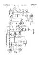
- a typical such transponder or translatoris illustrated in FIG. 7.
- the transponderis in many respects similar to a transceiver in that it possesses a pair of signal handling channels for operating in converse fashions on signals in opposite directions.
- the input/output terminals 424 and 426are served by channel 420 to handle signals in the direction of the arrow 428 while channel 422 handles signals in the opposite direction indicated by the arrow 430.
- Channel 420may receive at input/output terminal 424 the 1.5 mbits/s and 16 kbits/s signals, amplify the same via amplifier 432, and deliver the amplified signals to a mixer 434, fed by the oscillator 436.
- the mixingraises the frequency to the radio frequency range and this signal is passed through a filter 438 and amplifier 440 to the input/output terminal 426.
- the terminal 426would terminate in the antenna 410.
- the transponders 416 and 418 receiving the radio signal from the antenna 410would handle the incoming signals in a converse fashion through the channel 422.
- the radio frequency signalswould be received by an antenna connected to the terminal 426.
- This signalwould pass through amplifier 442, mixer 444, controlled by oscillator 446, filter 448, and amplifier 450.
- the upstream 16 kbits/s control signal from the ADSLis raised to radio frequency and transmitted back to the transponder 408.
- the radio frequency signalis translated back to the 16 kbits/s form and delivered upstream to the remote ADSL 205 for the control purposes described in connection with FIG. 1.
- transponder circuitsmay be utilized in a manner well known in the art. See, Radio Handbook, 23d edition, William Orr, SAMS Division of MacMillan Computer Publishing, 1987; Satellite Communications, Robert M. Gagliardi, Lifetime Learning Publications, 1984; and Digital Satellite Communications, 2d edition, Tri T. Ha, McGraw-Hill Communications Series, McGraw-Hill Publishing Company, 1990.
- FIG. 6there is shown another embodiment of wireless CPE distribution using an ADSL system. Similar reference numbers are used where applicable.
- a single CPE ADSL unitis utilized connected to the subscriber line 203 and feeding the 1.5 mbits/s and 16 kbits/s signals to the transponder 408. These signals are translated to radio frequency and transmitted in turn to transponders 416 and 418. The transponders translate the radio frequency back to the original 1.5 mbits/s and 16 kbits/s signals and deliver the same to the DET's 100 and 100'.
- the return or upstream 16 kbits/s control signalsare translated to radio frequency in transponders 416 and 418, transmitted to transponder 408 and there returned to the 16 kbits/s form for input to the ADSL 201 and transmission upstream to the remote ADSL 205.
- the telephone (POTS or ISDN) circuitis separated from the incoming signal on the subscriber line at the filter 402 (or equivalent) device in the case of an ISDN installation.
- the POTS lineis broken out from the ADSL as described in connection with FIG. 1.
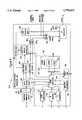
- FIG. 2depicts an example of one such advanced video dial tone network utilizing the Level 1 Gateway.
- the illustrated networkutilizes an advanced fiber to the curb system with ATM (Asynchronous Transport Mode) transport, and is similar to one of the networks disclosed in commonly assigned application Ser. No. 08/250,792, filed May 27, 1994, entitled “Full Service Network” (attorney docket No. 680-080), the disclosure of which is incorporated herein entirely by reference.
- the network of FIG. 2uses essentially a switched star type architecture.
- the Full Service Network illustrated in FIG. 2provides broadcast video distribution, archival video services and interactive multi-media services as well as a suite of narrowband services including plain old telephone service.
- the broadcast video serviceswill initiate from a broadcast type server, such as ATM video source 1101 or aa digitally encoded off the air TV signal.
- the broadcast server source 1101includes an actual analog video source 1110. Although only one is shown, a typical broadcast service provider will have a plurality of such video sources in the same or separate server systems.
- the analog signal from the sourceis carried by any convenient means, such as an optical fiber, etc.
- Means(not shown) are provided as necessary to convert analog video transmission signals, e.g. NTSC broadcast signals, to baseband video and audio signals.
- the baseband signalsare applied to a real time encoder 1120.
- the real time encoder 1120digitizes the audio and video signals and performs data compression. As currently envisaged, the encoder will encode the program signal into an MPEG 2 format.
- the illustrated real time encoder 1120preferably is set up as a bank of encoders to process six or more sets of analog audio/video program signals in parallel.
- the bank of encoders 1110produces six 6 Mbits/sec MPEG 2 bit streams, which are combined together with appropriate overhead information into a single 45 Mbits/sec DS-3 type signal.
- the DS-3 signal from the encoder 1120is input to an interworking unit (IWU) 1130.
- the interworking unit 1130is the actual input point for the encoded broadcast video information into the Full Service Network of FIG. 2.
- the Full Service Networkuses asynchronous transfer mode (ATM) switching to transport all broadband or video information, including the broadcast video information.
- ATMis a packet oriented time division multiplexing technique.
- informationis organized into cells. Each cell includes a header, primarily for identifying cells relating to the same virtual connection, and an information field or "payload".
- a 53 octet ATM cellwould include a cell header consisting of 5 octets and a payload consisting of 48 octets of data.
- One MPEG 2 packetwould be mapped into payload data in four such ATM cells. Transfer is asynchronous in the sense that the recurrence of cells that contain information from any particular sender is not necessarily periodic.
- Each device using the ATM networksubmits a cell for transfer when they have a cell to send, not when they have an assigned or available transmission time slot.
- ATMallows any arbitrary information transfer rate up to the maximum supported by the ATM network, simply by transmitting cells more often as more bandwidth is needed.
- all video materialswill be transferred at a constant, standardized bit rate.
- Preferred later generations of the networkwill utilize the ATM capabilities of the network to permit transmission of video information over channels of different bit rates, e.g. 1.5 Mbits/sec, 3 Mbits/sec, 6 Mbits/sec, etc. It will also be possible to vary the bit rate during communication on an as needed basis.
- the interworking unit 1130grooms the continuous MPEG 2 bit streams of the broadcast services for ATM cell stream transmission over optical fiber transport links. For example, the interworking unit will divide the bit stream into appropriate length payloads and combine the payload data with appropriate cell headers, necessary for ATM transport. In an initial implementation, downstream links would carry an OC-12 bit rate, but higher rate transports such as OC-48 will be used in later implementations. Assuming use of OC-12, one such transport link will normally carry the equivalent of 112 DS-3's. However, conversion into ATM cell format with associated headers imposes added overhead requirements on the data transmissions. In the presently preferred embodiment, one interworking unit 1130 therefore processes up to ten DS-3 signals to produce an ATM bit stream at the OC-12 rate.
- a transport interface 1140converts the electrical signal from the interworking unit 1130 into an optical signal and transmits the optical signal through fiber 1150 to an adaptive digital multiplexer (ADM) identified in the drawing as a video bridging and insertion device 1160.
- ADMadaptive digital multiplexer
- the ADM 1160performs three functions, passive bridging, active bridging and insertion of signals from other broadcast service providers (if any). The three functions may actually be separate, but in the preferred embodiment, all three would be performed by elements collocated within the one network component ADM 1160.
- the real time encoders 1120each output a single DS-3 signal comprising up to 6 MPEG 2 bit streams.
- the interworking unit 1130processes up to ten DS-3 signals to produce an ATM bit stream at the OC-12 rate. Consequently, one broadcast video source 1101 may produce as many as 60 channels of CATV type broadcast programming for transport over one OC-12 type SONET optical fiber 1150. Many providers, however, may not choose to broadcast so many channels. For example, the provider operating broadcast video source 1101 may offer only 42 channels. Such an ATM channel transmission on the optical fiber 1150 will not utilize the entire OC-12 channel capacity of that fiber. In the specific example, the 42 channels together require the equivalent of 7 of the available 10 DS-3's.
- the illustrated architecturepermits a second broadcast service provider to utilize the transport capacity not used by the first provider.
- the second broadcast service providerwould offer additional channels from a separate second source 1101'.
- the source 1101'is essentially identical in structure and operation to the source 1101, but the source 1101' will offer up to the number of channels necessary to fill the OC-12 transport capacity. In the example, if the source 1101 transmits 42 channels (7 DS-3's) via the fiber 1150, the second source 1101' could transmit up to 18 additional channels (3 DS-3's).
- the function of the insertion device in the ADM 1160is to combine the signals from the two sources into a single OC-12 rate signal (10 DS-3's in ATM cell format) for further transmission through the optical network.
- the two bridging functionsfacilitate dissemination of the broadcast material throughout the entire Full Service Network.
- the passive bridging elementsare optical splitters for splitting one OC-12 optical signal from the insertion device into a number of duplicates thereof, e.g. 1:2, 1:4, 1:8, etc.
- the active bridging elementsconvert an optical signal to an electrical signal, regenerate the electrical signal and convert the regenerated signal back to an optical signal for application to multiple output ports.
- the optical OC-12 output signals from the bridging componentsare transmitted over a large number of optical fibers 1170 to host digital terminals throughout the network service area.
- the host data terminal (HDT) 1180is shown as a representative example.
- the digital entertainment terminal (DET) in the subscriber's homeprovides a signal identifying the selected channel to the HDT 1180.
- the signalling between the digital entertainment terminal (DET) and the HDT 1180will be discussed in more detail below.
- the ATM cell stream from an optical fiber 1170is applied to a bus.
- One HDTwill communicate with a large number of optical network unit (ONU's) 1210, two of which are shown.
- the HDTwill communicate with each ONU 1210 via a pair of optical fibers 1190.
- each home or living unitwill have as many as four DET's.
- Each ONU 1210 and the downstream fiber of the pair 1190 to the ONU 1210will provide downstream video services to a number of homes, e.g. 8 to 24.
- the transmissions on the downstream fibers between the HDT and the ONU's 1210are synchronous, although the video information remains in ATM cell format.
- Each DET served by an ONU 1210is assigned a specified time slot on the downstream fiber of a pair 1190.
- the HDT 1180includes a component which is essentially a non-blocking type ATM switch.
- the HDT 1180accesses the appropriate bus and identifies each ATM cell on that bus for which the header information indicates that the cell represents information for the selected broadcast channel.
- the identified ATM cellsare bridged by the ATM switch from the bus to a line card providing transmissions over the optical fiber 1190 to the particular ONU 1210 which services the requesting subscriber's premises.
- elements on the line card communicating with the particular ONUwill buffer the cell as necessary and place the cell in the time slot for that DET on the downstream fiber of optical fiber pair 1190.
- the cells selected for a particular DETtogether with cells going to other DET's served by the same ONU multiplexed into their respective time slots, are applied to an electrical to optical converter and transmitted over the downstream fiber to the ONU 1210 serving the particular subscriber's premises.
- the basic purpose of the ONUis to desegregate the HDT side links into individual customer links and provide optical to electrical conversion for electrical delivery to the individual subscribers' premises.
- the drop cable to each subscriber's premisescomprises a coaxial cable for carrying the video and/or two-way digital data signals and a twisted wire pair for carrying telephone signalling.
- ADSL communications over twisted wire paircould be used between the ONU and the subscribers premises.
- the ONUincludes means to convert optical signals received over the downstream fiber to electrical signals and transmit signals from each DET's assigned time slot down over the coaxial cable to the subscriber's premises.
- the ONUalso provides two-way conversion between optical and electrical signals for voice telephone service over the twisted wire pairs and for the signalling channels to/from the DET's.
- a power source 1211supplies -130 V dc and battery reserve power for telephone service to the ONU's 1210.
- the power source 1211may connect to the ONU's via twisted pairs, but in the preferred embodiment, the power is carried over a coax distribution cable.
- the digital entertainment terminal (DET) 1217is a programmable device to which different applications programs and/or portions of the operating system will be downloaded from a gateway device in order to permit the DET to interact with different information service providers and thereby offer the user totally different types of services.
- the DETmay be similar to that used in the network of FIG. 1, with the exception that the network interface module within the DET 1217 provides the various broadband and signalling connections to a coaxial cable, instead of to an interface to an ADSL twisted wire pair type line, and the communication software within the DET is adapted to process ATM transported information.
- the DET 1217includes means (not shown) to demodulate received data and convert ATM cell stream data into bit stream data for further processing.
- the DET 1217also includes a digital signal processor to decompress received video signals as well as a graphics display generator for generating displays of text data, such as the initial turn-on selection menu.
- the DETwill also include a digital to analog converter and appropriate drivers to produce output signals compatible with a conventional television set.
- Each DET 1217also includes the means to receive selection signals from a user and transmit appropriate data signals over a narrowband channel on the coaxial drop cable to the ONU 1210.
- the ONUmultiplexes the user input data signals from the DET's it services together and transmits those signals to the HDT over an upstream fiber of the optical fiber pair 1190.
- the HDTtransmits the upstream control signals to control elements referred to as gateways.
- the HDT'scommunicate with the gateways through an X.25 type data network. Future implementations will use ATM communications for the signalling.
- the Level 1 Gateway 1230provides primary control of all routing and access functions of the network and accumulates various usage statistics, in a manner substantially similar to that of the Level 1 Gateway 221 in the network of FIG. 1.
- the control functionsinclude controlling access to broadcast programs by individual subscribers. Control of access to on demand programming and interactive multimedia services through a PVC controller 1420 and an ATM switch 1410 will be discussed in more detail below.
- the Level 1 Gatewayalso will transmit narrowband information to the DET 1217 instructing it to initiate display of various selection menus of available video information service providers.
- the Level 1 Gatewayconnects to a service administration module (SAM) which maintains a data base of video information service providers and customer profile data for the broadcast, archival and interactive video services available through the network. This data may include customized menus, pre-subscription information, identification of impulse pay per view events and premium channels, etc. Under different circumstances, the video information providers and/or the individual customers can access this data for provisioning.
- SAMservice administration module
- the Level 1 Gatewayalso connects to an operations support module (OSM).
- OSMoperations support module
- the operations support moduleprovides an interface to standard operating support systems used for additional network provisioning functions.
- the DET 1217transmits data upstream through the various network elements to the Level 1 Gateway identifying the selected channel.
- the Level 1 Gateway 1230accesses stored data regarding the broadcast services to which the customer currently subscribes. If the customer subscribes to the requested service, the Level 1 Gateway 1230 transmits an instruction to the HDT 1180 to route the cells for that channel to the subscriber's DET 1217 in the manner discussed above. If the customer is not currently a subscriber to that service, the Level 1 Gateway 1230 transmits a data message back to the DET 1217 instructing it to provide an appropriate television display, e.g. informing the customer of a service denial and/or asking the subscriber for appropriate inputs to initiate a new subscription.
- the above selection procedure through the Level 1 Gatewayprovides the Gateway 1230 with information as to each selection a subscriber makes and when the selection is made.
- the Level 1 Gatewayalso receives information as to when a DET session ends, e.g. upon turn-off of the DET or upon request for a session with a different provider.
- the Level 1 Gatewayhas all information necessary to accumulate a variety of statistics as to viewer usage both for billing purposes and for audience accounting purposes.
- certain relevant control datacould be downloaded to the HDT, either from the Gateway 1230 or from the service administration module (SAM).
- SAMservice administration module
- the broadcast VIP'swould provide provisioning data to the SAM, and the SAM periodically downloads that data to the appropriate HDT's, either directly or through the Level 1 Gateway 1230.
- the provisioning data downloaded to the HDT's 1180would include channel mapping information and subscriber authorization control information.
- the channel mapping informationspecifies what programs are carried on each ATM virtual circuit, within each DS-3, on each respective optical fiber 1170.
- the HDT 1180accesses the channel mapping information in response to each program selection by a subscriber to route the ATM cell stream to the requesting DET.
- the authorization control datawould indicate which program each subscriber is authorized to access, e.g. because that party has subscribed to the particular program service and is not delinquent in bill payments. When a subscriber requests a program, the HDT 1180 would check this data to determine whether or not to supply the program to the subscriber's DET 1217.
- the HDT 1180As the HDT 1180 routes selected channels to the DET's 1217, the HDT would accumulate usage data and/or pay per view event purchase data for the subscribers serviced thereby. The HDT 1180 would periodically upload such usage data to the Level 1 Gateway 1230 and/or to the SAM for subsequent transmission to appropriate billing systems of the network service provider or the VIP's, respectively.
- the network of FIG. 2offers subscribers access to other wideband services, such as video on demand and interactive multimedia services. Access to these additional broadband services is through an ATM switch 1410. As discussed in more detail below, the access through this switch is controlled by the Level 1 Gateway 1230 in a manner quite similar to the routing to a VIP in the network of FIG. 1.
- Each of the non-broadcast service providers 1400will have a level 2 Gateway 1401 and some form of file server 1403 or other source of information.
- the video information provider's (VIP's) systemmay provide ATM cell stream outputs for transmission through the network.
- the network operatorwould supply an interworking unit similar to the unit 1130 discussed above to convert the provider's bit stream data into an ATM cell stream format compatible with the Full Service Network.
- the ATM switchtransmits selected ATM cells via optical fibers 1415 to the HDT's 1180.
- a PVC controller 1420stores data tables defining all possible virtual circuits through the ATM switch and the HDT's to each terminal of a customer subscribing to a particular provider's services. These data tables define the header information and the particular fiber output port used to route cells to the correct HDT and the time slot information on the downstream fiber to the appropriate ONU serving each DET. The data tables thus define "permanent virtual circuits" (PVC's) between the providers and the DET's.
- the subscriber's DET 1217When a subscriber initiates a session with a broadband interactive service provider, for example VIP 1400, the subscriber's DET 1217 provides an appropriate "off-hook" signal to the HDT 1180.
- the HDT 1180sends the message through the X.25 packet switched network to the Level 1 Gateway 1230.
- signallingmay also be achieved using ATM calls through.
- HDT and ATM video switchto the level 1 Gateway 1230.
- the Level 1 Gateway 1230receives the addressed message from the HDT, that Gateway uses the X.121 or other protocols address of the caller included in the message to check its internal database to determine if the caller is a valid network customer. If the caller is not a valid customer, the system tears downs the session. If the caller is a valid customer, the Level 1 Gateway 1230 transmits an X.25 or ATM call accept message back to the terminal and waits for the first application level message.
- the DET 1217sends an initiation message that says "hello".
- This "hello" messageincludes basic information such as a customer premises equipment (CPE) identifier and a CPE type designation.
- the Level 1 Gateway 1230sends a menu and a banner through the downstream signalling channel, as in the earlier network embodiment.
- the menuis a screen of text listing VIP's available to this customer or the VIP's that the customer as previously selected for purposes of her customized menu presentation.
- the subscriberreviews the menu on their television set, and operates the arrow keys on the DET remote control to move a cursor across the menu to an appropriate point on the screen, after which the user presses an ⁇ ENTER> key on the keypad or remote control.
- the DET 1217transmits an appropriate data signal upstream through the network to the Level 1 Gateway 1230.
- the Level 1 Gatewaymay execute a PIN number access routine, as in the earlier embodiment, if the subscriber has previously requested such access control for selected ones of the VIP's. For simplicity here, it is assumed that the currently selected VIP is not subject to such a PIN number requirement.
- the Level 1 Gatewayis merely expecting to receive the VIP selection input from the DET within a predetermined period following the menu transmission. If the Level 1 Gateway receives the selection input message from the DET within the predetermined period, the Gateway 1230 translates that message into the 4 digit code for the selected VIP's Level 2 Gateway.
- the Level 1 Gatewaysends a message to the DET saying please wait while we connect to the VIP.
- the Level 1 Gatewaythen goes over the X.25 or ATM network to communicate with the selected VIP's Level 2 Gateway.
- the Level 1 Gateway 1230contacts the level 2 Gateway 1401 and indicates that it has a customer calling.
- the Level 1 Gateway 1230identifies the customer to the level 2 Gateway 1401 by sending the standard billing telephone number for the calling customer to the Level 2 Gateway.
- the CPE identification information and the CPE-type information that was sent in the initial origination messageis also sent to the Level 2 Gateway (VIP) at this time.
- VIPLevel 2 Gateway
- the VIP's Level 2 Gatewaymay accept or reject the call after receiving the initial request indicating a customer is available, as in the network of FIG. 1. If the Level 2 Gateway 1402 sends a message back to the Level 1 Gateway 1230 indicating a rejection of the call, the Level 1 Gateway transmits a message to the DET 1217 instructing that terminal to display some form of call rejection notice on the associated TV.
- the Level 2 Gateway 1401accepts the call, provides a server output port and gives a port identification for the port on the server 1403 to the Level 1 Gateway 1230.
- the Level 1 Gatewaytransmits the X.121 address of the calling customer's DET 1217 to the Level 2 Gateway 1401.
- the Level 2 Gatewayuses that address to initiate a new signalling communication through the X.25 network 1220 with the subscriber's set-top terminal DET 1217.
- the Level 1 Gatewayidentifies the broadband communication link number for the channel going out from the HDT to the requesting customer's DET 1217.
- the Gateway 1230sends a message to the PVC controller 1420 to establish a virtual circuit between the selected provider 1400 and the subscriber's DET 1217.
- the PVC controlleraccesses its data tables to identify an available permanent virtual circuit between the provider 1400 and the DET 1217 for which all necessary elements are currently available.
- the PVC controller 1420provides appropriate instructions to the ATM switch 1410 and informs the Level 1 Gateway 1230 of the virtual circuit identifier.
- the Level 1 Gateway 1230informs the HDT 1180 of that virtual circuit identifier and instructs the HDT 1180 to "lock-up" that circuit as a currently active virtual circuit providing broadband communications from the server 1403 of the provider 1400 to the subscriber's DET 1217.
- the PVC controller 1420transmits back an appropriate indication thereof to the Level 1 Gateway 1230. Then the Level 1 Gateway tears down its own X.25 signalling connection with the subscriber's set-top terminal. At the same time, the Level 1 Gateway 1230 informs the Level 2 Gateway 1401 that it has set up a good broadband link, and the Level 1 Gateway initiates a billing record for the call. Alternatively, if the PVC controller 1420 informs the Level 1 Gateway 1230 that it could not establish the broadband connection, the Level 1 Gateway passes that information on to the Level 2 Gateway 1401 and provides an appropriate message for display by the DET 1217 informing the customer.
- the DETcan transmit control signalling upstream through the ONU 1210 the HDT 1180 and the X.25 data network to the Level 2 Gateway 1401.
- the Level 2 Gatewaycan also send signalling information, such as control data and text/graphics, downstream through the same path to the DET 1217.
- the server 1403will provide ATM cells with an appropriate header.
- the ATM switch 1410will route the cells using the header and transmit those cells over fiber 1415 to the HDT serving the requesting subscriber.
- the HDT 1180will recognize the header as currently assigned to the particular DET 1217 and will forward those cells through the downstream fiber of pair 1190 and the ONU 1210 to that DET, in essentially the same manner as for broadcast programming.
- the Level 2 Gatewayinstructs the Level 1 Gateway 1230 to tear down the broadband connection.
- the instructionincludes the customer's billing telephone number and the server port identification for the VIP port used for the broadband communication.
- the Level 1 Gateway 1230stops the billing timing for that broadband session and transmits and instruction through the PVC controller 1420 to tear down the broadband connection between the server port and the customer's broadband port.
- the Level 1 Gatewaycreates a log record of the interactive broadband call for purposes of billing the VIP 1400 for the broadband connect time.
- the Full Service Network illustrated in FIG. 2will also provide narrowband transport for voice and narrowband data services.
- a digital switch 1310 or an analog switch 1330will provide standard type plain old telephone service (POTS) for customers of the Full Service Network.
- POTSplain old telephone service
- the digital POTS switchprovides a DS-1 type digital input/output port through interfaces conforming to either TR008 or TR303.
- the outputmay go to a digital cross-connect switch (DCS) 1320 for routing to the various HDT's or directly to a multiplexer (MUX) 1325 serving a particular HDT.
- the MUX 1325may also receive telephone signals in DS-1 format from the analog switch through a central office terminal 1333.
- the central office terminal 1333converts analog signals to digital and digital signals to analog as necessary to allow communication between the analog switch 1330 and the rest of the network.
- the MUX 1325serves to multiplex a number of DS-1 signals for transmission over one fiber of an optical fiber pair 1335 to the HDT 1180 and to demultiplex signals received over the other fiber of the pair 1335.
- the fiber pairs between the HDT 1180 and the ONU's 1210will also have a number of DS-1 channels to carry telephone and narrowband data signals to and from the subscriber's premises.
- the subscribers' drops 1215include both a coaxial cable and one or more twisted wire pairs.
- the ONUwill provide telephone signals and appropriate power to the subscribers' premises over the twisted wire pairs connected to subscribers' telephone sets 1219.
- the ONU'swill also provide two-way narrowband data communication to the DET's in narrowband channels over coaxial cable.
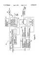
- FIG. 3depicts an alternate implementation of a further video network utilizing a Level 1 Gateway in accordance with the present invention.
- the network of FIG. 3is a hybrid fiber-coax system which provides RF transport of both analog and digital broadband services.
- the illustrated networkprovides broadcast video distribution, archival video services and interactive multi-media services as well as plain old telephone service.
- a telcodeploys a number of Loop Transport Interfaces 300, only one of which appears in the drawing (FIG. 3).
- each Loop Transport Interface 300will be located in a telco central office.
- several different central officeswould each have a Loop Transport Interface similar in structure to the Interface 300 depicted in FIG. 3.
- each Loop Transport Interfacewill serve as the headend of an otherwise conventional optical fiber trunk and coaxial cable type CATV distribution network.
- a laser type optical transmitter 303transmits downstream signals through fibers 305 to optical to electrical nodes referred to as "optical network units" or ONU's.
- the laseroperates in a linear mode in the range of 5-750 MHz.
- the transmitterhas an optical splitter and can transmit to several ONU nodes 309. Each ONU 309 performs optical to electrical conversion on the downstream signals and supplies downstream RF electrical signals to a coaxial cable distribution system 311.
- the optical transmitterreceives and transmits signals from an RF (radio frequency) combiner 315.
- the combiner 315combines and levelizes RF signals from several sources to produce the appropriate signal spectrum for driving the optical transmitter 303.
- One set of signals supplied to the RF combiner 315will be group of AM--VSB (amplitude modulated vestigial sideband) analog television signals from one or more appropriate sources not separately shown.
- AM--VSBamplitude modulated vestigial sideband
- Such signalsare essentially "in-the-clear" CATV type broadcast signals capable of reception by any subscriber's cable ready television set.
- the analog television signalsare broadcast from the optical transmitter 303 through the tree and branch optical and coax distribution network to provide "basic" CATV type service to all subscribers on the network.
- the Network operating companyoffers a standard CATV type analog frequency converter, or the subscriber could choose to purchase a converter on the open market.
- the network interface module in the DET 100awill also include a tuner that permits subscribers to the digital services to receive the analog broadcast channels through the same equipment used for the digital services.
- the Network depicted in FIG. 3also provides transport for digitized and compressed audio/video programming, both for certain broadcast services and for interactive services, such as video on demand. Such programming will be encoded and compressed in MPEG-2 or other format. As discussed in more detail below, the present invention permits specific use of MPEG encoded materials to offer a variety of interactive services without continuously utilizing a full MPEG encoded broadband channel to transport information to the subscriber's DET 100'.
- the MPEG encoded videois transported to each Loop Transport Interface using asynchronous transfer mode (ATM) transport and switching.
- ATM informationis organized into cells each comprising a header, primarily for identifying cells relating to the same virtual connection, and an information field or "payload".
- the ATM cell header informationincludes a virtual circuit identifier/virtual path identifier (VCI/VPI) to identify the particular communication each cell relates to.
- VCI/VPIvirtual circuit identifier/virtual path identifier
- the VCI/VPIwill identify a particular program channel.
- the VCI/VPI in each header of the ATM cellswould effectively identify a specific end point of the virtual communication link.
- digital broadcast service signals 318 in MPEG encoded form and arranged in ATM cell packetsare applied to an ATM packet handler 319 in the Loop Transport Interface 300.
- These broadcast service signalsoriginate in one or more broadcast VIP's ATM servers which are essentially the same structure as the servers/sources 1101, 1101 shown in FIG. 2.
- the ATM broadcast serviceswill carry premium service type programming.
- the ATM broadcast signalsmay originate from any appropriate source (not shown).
- the ATM broadcast cell stream signalsoriginate from a server 403', as discussed in more detail below.
- Fully interactive broadband digital signals, in MPEG--ATM formatare also applied to the ATM packet handler from an ATM switch 401.
- the ATM packet handler 319terminates all ATM cell transport through the Network. This handler receives the ATM cell streams and converts the cell payload information into MPEG 2 bit streams.
- the RF combiner 315which prepares signals for downstream transmission by the optical transmitter 303 receives a variety of other analog RF signals from a group of RF digital modulators.
- the RF analog outputs from the modulatorscarry digital broadband information.
- the content for the digital RF modulatorscomes from the ATM packet handler 319.
- a network controller 323 and an associated network data processor (NDP) 325use the VCI/VPI header from the ATM cells to control the ATM packet handler 319 to route the MPEG bit streams to the appropriate ones of the digital RF modulators 317.
- U.S. Pat. No. 5,231,494 to Wachobteaches quadrature phase shift keyed (QPSK) modulation of a plurality of video, audio and data signals into a single data stream within a standard six MHz channel allocation for transmission over a CATV type distribution network.
- QPSKquadrature phase shift keyed
- the currently preferred implementationuses 64 QAM (quadrature amplitude modulation) or 16 VSB (vestigial sideband) modulation techniques in the RF modulators 317 in the Loop Transport Interface 300.
- 64 QAMquadrature amplitude modulation
- 16 VSBvestigial sideband modulation techniques
- 4 channels of 6 Mbits/s MPEG encoded digital video informationcan be modulated into one 6 MHz bandwidth analog channel.
- 16 VSByields 6 channels of 6 Mbits/s MPEG encoded digital video information modulated into one 6 MHz bandwidth analog channel.
- Each RF modulatorproduces a 6 MHz bandwidth output at a different carrier frequency.
- the 6 MHz bandwidth RF signals from the modulators 317are supplied to the optical transmitter 303 for downstream transmission together in a combined spectrum with the AM--VSB analog television signals 316.
- the downstream transport of the digital programmingis an RF transmission exactly the same as for the analog basic service channels, but each of the channels from the RF modulators 317 contains 4 or 6 digitized and compressed video program channels, referred to hereinafter as "slots".
- the 6 Mhz digital program channelswill be carried through the fiber and coaxial system in standard CATV channels not used by the analog basic service programming.
- the ONU 309is essentially transparent to both the analog basic service channels and the channels carrying the digital programming and supplies all of the signals as a combined broadcast over the coaxial cable network 311.
- the optical fiber 305 from the transmitter, the ONU's 309 and the coaxial distribution systems 311 thereforprovide a broadcast network transporting all downstream programming to all subscriber premises serviced thereby.
- a network interface modulecouples the set-top device or digital entertainment terminal (DET) 100a to a drop cable of the coaxial distribution network 311.
- the NIMincludes an analog frequency tuner controlled by a microprocessor to selectively receive the RF channel signals, including those channels carrying digital information.
- the NIMalso includes a QPSK, QAM or VSB demodulator to demodulate a selected one of the digitized program signals carried in one of the digital slots within a received 6 MHz channel and will perform a forward error correction function on the demodulated data.
- the digital audio/video signal processor 2125 within the DETdecompresses received video signals, generates graphics display information and performs digital to analog conversion to produce output signals compatible with a conventional television set 100', exactly as in the earlier embodiments.
- the analog tuner in the NIMwill tune in all channel frequencies carried by the network, including those used for the analog broadcast services.
- the DET 100aincludes a bypass switch or the like and an analog demodulator to selectively supply analog signals from the basic service channels directly to the audio/video output terminals or to the modulator, to provide signals to drive a standard television receiver.
- the DET 100atherefore can be used as a frequency converter for reception of the analog signals.
- each DET 100aincludes a remote control and/or keypad to receive various selection signals from a user. At least in response to certain user inputs, such as selection of a pay per view event, the DET will relay data signals upstream over a signalling channel on the coaxial cable to the ONU 309. The actual transmission of any such data signals upstream from the DET 100a occurs in response to a polling of the DET by the ONU 309. The ONU 309 combines upstream data signals from the DET's serviced thereby and transmits those signals upstream over another optical fiber 307 to an optical receiver 308 in the Loop Transport Interface 300. Each DET 100a may transmit data on a different carrier frequency, in which case the network controller knows which DET sent particular data based on the received frequency channel. Alternatively, for interactive services, the DET may transmit a unique identification code with the upstream message.
- Certain digital program signals carried on the networkmay be encrypted using encryption technology and key codes. Details of specific encryption algorithms, the key codes and the precise techniques for downloading the key codes to the DET's are well known to those skilled in the art and familiar with the relevant patents and literature.
- an ACC 4000D 331serves as a video administration module (VAM). Obviously other equivalent products may be substituted.
- the ACC 4000D or VAMperforms set top management and specific program access control functions.
- service profiles for each customer on the network and their DET'sare set up and stored within the Level 1 Gateway 411.
- the Level 1 Gateway 411may also provide an interface to appropriate billing systems (not shown) for some broadcast services, such as pay per view.
- a subscriberwhen a subscriber first signs up, a portfolio of channels subscribed to by that customer is established in the subscriber's profile data within the VAM 331. Based on this profile data, the VAM will download a service map into the subscriber's DET 100a.
- the downstream transmission portion of the networkprovides an out-of-band downstream signalling channel to the DET's, for example for the downloading of the service map information from the VAM 331 to each DET 100a.
- This downstream signalling channelalso carries signals for controlling software downloading and/or selection of certain channels or frames for decoding in interactive services.
- each DET 100aincludes means for receiving and decoding each such digital broadcast service channel, as discussed above with regard to FIG. 1.
- the microprocessor in the DET 100acontrols access to any of these channels based on the downloaded map information stored in the system memory. For example, if one subscriber requests HBO, and that subscriber has paid to subscribe to HBO, the subscriber's DET 100a will contain map information instructing it to tune the RF channel and select and decode the digital program slot carrying HBO for display on the subscriber's television set 100'. However, if a requesting subscriber has not paid for HBO, the downloaded service map will not provide the requisite data for tuning and decoding of that channel.
- the illustrated Networkalso offers pay per view services through the ATM broadcast program channels 318.
- a userselects a pay per view event by operating the DET 100a.
- the DET 100atransmits a purchase message upstream through the Loop Transport Interface 300 to the Level 1 Gateway 411. If the authorization data in the subscriber's profile in the Level 1 Gateway indicates that the DET identification is valid and the subscriber is authorized to purchase such events, the Level 1 Gateway instructs the video manager 417 to authorize reception (and provide a decryption key if needed).
- the DET 100adecodes the pay per view event in essentially the same manner as for other premium services carried on the ATM broadcast channels 318, as outlined above. If the decryption key is needed, the Level 1 Gateway 411 actually instructs the video manager 417 to instruct the VAM 331 to transmit the key to subscriber's DET 100a.
- the implementation of the network illustrated in FIG. 3also provides telephone service. Between the optical network unit and the subscriber premises, the 700-750 MHz portion of the spectrum on the coaxial cable will carry the telephone signals. This allocated spectrum provides transport for 24 DS0 telephone channels. Each subscriber premises will have telephone interface referred to as a Cable Network Unit (CNU) 340 coupled to the coaxial cable which serves to couple two-way signals between a twisted wire pair into the home and the telephone frequency channels on the coaxial cable 311.
- CNUCable Network Unit
- Carrier frequencies used for telephone servicesmay be individually assigned to particular subscriber's CNU's. Also, the telephone signal spectrum is carried on the same two fibers that carry the video and the upstream signalling between the Loop Transport Interface and the ONU.
- Upstream telephone signalsare applied from the optical receiver 308 to a host digital terminal (HDT) 343 which provides an interface to a standard digital telephone switch 345. Downstream telephone signals from that switch pass through the HDT 343 to the RF combiner 315 for transmission in the 700-750 MHz frequency range over the fiber to the ONU 309 and the coaxial cable distribution system 311.
- HDThost digital terminal
- the Loop Transport Interface 300would dynamically allocate the DS0 channels on the coaxial cable system 311 on a time-sharing basis, in essentially the same manner as in mobile radio systems. Two additional fibers and a second optical transmitter and receiver pair would carry the two-way telephone signals to and from the ONU 309. Because of the use of the separate optical links for telephone service in this alternate implementation the HDT and telephone switch need not be closely associated or collocated with any particular one of the Loop Transport Interfaces.
- each VIPhas a Level 2 Gateway and some form of broadband information file server 403.
- the ATM switch 401provides communications links between the Loop Transport Interfaces 300 and the Level 2 Gateways and file servers 403.
- Customer access to the VIP'sis controlled through one or possibly more programmed computer or processor elements performing the processing functions of the Level 1 Gateway 411.
- a permanent virtual circuit (PVC) controller 415 and a video manager 417respond to signals from the Level 1 Gateway to control the point to point routing through the Network.
- PVCpermanent virtual circuit
- the PVC controller 415stores data tables defining all possible virtual circuits through the ATM switch 401 and the Loop Transport Interface 300 serving each DET terminal of a customer subscribing to each particular provider's services. These data tables define the header information and the switch port to the packet handlers needed to route cells to the correct Loop Transport Interface.
- the video manager 417stores similar data tables identifying the transmission fiber ports, RF channels and multiplexed digital channel slots which may be used to transport each data stream processed by the ATM packet handler 319 through the fiber 305 to the appropriate ONU 309 serving each DET.
- the data tables in the PVC controller 415 and the video manager 417thus define "permanent virtual circuits" between the VIP's equipment 403 and the DET's 100a.
- the subscriberoperates the DET 100a to interact with the Level 1 Gateway 411 and select a VIP in a manner similar to the operation in the network of FIG. 1.
- the PVC controller 415responds to instructions from the Level 1 Gateway by activating the ATM switch 401 to establish a downstream virtual circuit path between a port of the VIP's server and the ATM packet handler within the Loop Transport Interface 300 servicing a subscriber requesting a call connection to the particular VIP.
- the video manager 411assigns a particular one of the digitized video channel slots in a digital program type RF channel to carry the particular point to point communication.
- the video managercontrols the ATM packet handler 319 to route MPEG data recovered from the ATM cells for the particular point to point communication to the port for one of the RF modulators 317 so that the modulator will include the MPEG data in the assigned digital channel slot within a particular 6 MHz RF channel.
- the video manager 417also transmits a signal downstream through the signalling channel to the subscriber's DET 100a instructing the DET to tune to the particular RF channel and decode MPEG data from the specifically assigned digital channel within that RF channel.
- Similar dynamic assignments of RF channels on a CATV system to individual terminals for interactive servicesare disclosed in U.S. Pat. No. 5,220,420 to Hoarty et al. and U.S. Pat. No. 5,136,411 to Paik et al., the disclosures of which are incorporated herein in the entirety by reference.
- Level 1 Gateway 411would instruct the PVC controller 415 to control the ATM switch 401 to establish an upstream virtual circuit for control signals sent from the DET 100a up through the fiber-coax network and receiver 308 to the VIP's level 2, gateway.
- the combination of upstream and downstream, point to point channelsare used for downloading of operating system and applications software and for interactive service communications in essentially the same manner as in the Video Dial Tone Network of FIG. 1.
- the Level 1 Gateway 411receives status and failure notifications as part of its ongoing operations. These functions of the Gateway 411 are quite similar to those of the Gateway 212 in the network of FIG. 1 except that the Gateway 411 receives event notifications from more elements of the network. Also, in the presently preferred embodiment of the network of FIG. 3, the function of monitoring communications between the loop transport interface 300 and individual subscribers' DET's 100a is an automatic function of the video manager 417. In such an embodiment, there is no longer a need for the video provider service center (VPSC).
- VPSCvideo provider service center
- the video managermonitors 417 operations of the loop transport interface 300. As part of its monitoring function, the video manager 417 also determines the status of communications to each DET 100a. As such, the video manager automatically knows the status of all components between the input ports to the loop transport interface and the output ports of the DET's 100a.
- the video manager 417could periodically transmit a status interrogation signal to each DET 100a, through the out-of-band signalling channel. If currently operable, the DET would transmit a status message back upstream through the signalling channel informing the manager 417 of the DET's status, e.g. operable but idle or operable and actively in-service.
- a DET 100a detecting some problemcould transmit a fault signal upstream through the signalling channel to the video manager 417, either immediately in response to fault detection or in response the next periodic interrogation by the video manager.
- the video manager 417would also interpret a failure of a DET 100a to respond to an interrogation or to confirm any other message sent to the DET within a predefined period of time as a fault condition.
- the Level 1 Gateway 411may receive an indication from the PVC controller 415 and/or the video manager 417 that one or both can not establish a desired broadband connection.
- the PVC controller 415also monitors ongoing operations of the ATM switch 401, and the video manager 417 monitors communications through the loop transport interface 300 at all times, and each will inform the Level 1 Gateway 411 upon detection of any fault or interruption in any currently established broadband connection.
- the Level 1 Gateway 411transmits notice of an inability to establish a desired broadband session through the signalling channel to the requesting DET 100a, using notices such as shown in FIGS. 2F and 2G depending on whether or not other VIP's are available to the particular subscriber at the time of the call.
- Level 1 Gateway 411receives notice of a fault in an already established session, the Gateway 411 stops accumulating billing data for that session and transmits a message regarding the failure to the VIP's Level 2 Gateway.
- the Level 2 Gatewaymay provide an appropriate notice to the subscriber through the signalling link, if that portion of the session is still operative. Alternatively, the Level 1 Gateway may transmit an appropriate display notice to the DET 100a through the signalling channel.
- Level 1 Gateway 411instructs the PVC controller 415 and the video manager 417 to tear down a broadband communication session
- the Gateway 411expects responses from both of those controllers 415, 417 within a predetermined time interval. If either the PVC controller 415 or the video manager 417 does not respond within the predetermined time interval, the Level 1 Gateway 411 will send an ABORT message to the non-responsive controller 415 or 417 to cancel the original session establishment message, and the Gateway 411 will also record the failure in an alarm file.
- the DETwill connect to a number of different types of networks, such as the Video Dial Tone Network shown in FIG. 1, and more advanced video distribution networks disclosed in commonly assigned application Ser. No. 08/250,792 filed May 27, 1994, entitled “Full Service Network” (680-080), the disclosure of which is incorporated herein entirely by reference.
- the DET 2100will include a network interface module 2101 providing the actual physical connection to the particular type of network.
- the network interface module 2101will also perform any format conversion necessary between signal formats utilized by the network and signal formats used within the DET 2100.
- the module 2101presents two connections to the rest of the DET, a high bit rate broadband connection and a low bit rate signalling connection.
- the broadband connectionis a one-way downstream only connection, but the low bit rate signalling connection is a two-way connection.
- the network interface modulewould provide corresponding connections to an in home ADSL multiplexer unit.
- the ADSL unitcould be included as one or more additional chips within the DET.
- the network interface modulewould include means to multiplex and demultiplex signals for transmission/reception over the coaxial cable or optical fiber.
- the network interface modulewould also include the means to physically connect to the particular network.
- the modulewould include a means for two-way conversion between electrical and optical signals and connections to one or more optical fibers for the necessary two-way transmission.
- the network interface module 2101takes the form of a plug in module.
- the module 2101would be similar to a daughter board or option card which can be plugged into a back plane of a personal computer (PC).
- PCpersonal computer
- typically a techniciancould replace the module in either the field or the shop, to modify a DET to connect to and communicate over a different network, and the technician would modify associated communications control software in the system memory.
- Alternative implementationsmay use a user replaceable cartridge type network interface module, similar to a video game cartridge, which may include memory in the module for storage of the communications control.
- the network interface modulecould include a digital signal processor controlled by the CPU of the DET and input/output connections compatible with all of the digital broadband networks currently available. The downloaded operating system software stored in the system memory of the DET would control operations of the digital signal processor to send and receive signals in accord with the particular network the subscriber chooses to connect the DET to.
- the DET 2100includes a CPU 2105, comprising a 386 or 486 microprocessor 2110 and associated system memory 2120.
- the system memory 2120includes at least 2 mbytes of volatile dynamic RAM 2122 and 1 mbyte of non-volatile RAM 2121.
- the microprocessor 2110includes a small amount of ROM (not shown) storing "loader" programming needed to control wake-up.
- An EPROM memory(not shown) also may be added.
- a digital audio/video signal processor 2125controlled by the CPU 2105, produces digital uncompressed audio and video signals from the audio and video MPEG encoded packets received from the network through the interface module 2101.
- the audio/video processor 2125includes an MPEG system demultiplexer 2127, an MPEG video decoder 2129, an MPEG audio decoder 2131, a graphics overlay controller 2133 and at least two frames (e.g. 8 mbytes) of video RAM 2135.
- the MPEG system demultiplexer circuitry 2127recognizes packets in the MPEG data stream received over the broadband channel through the network interface module 2101 and routes the packets to the appropriate components of the DET. For example, the MPEG system demultiplexer 2127 circuitry recognizes audio and video packets in the MPEG data stream and routes those packets to the decoders 2129, 2131, respectively.
- the MPEG video decoder 2129decompresses received video packet signals to produce a digital video signal
- the MPEG audio decoder 2131decompresses received audio packets to produce left and right digitized stereo signals.
- the MPEG decoders 2129, 2131may be controlled in response to signals from the microprocessor 2110.
- the MPEG video decoder 2129will internally include at least two frames (e.g. 8 mbytes) of RAM (not separately shown) for use as a frame reorder buffer during the MPEG video decoding process, and the MPEG audio decoder 2131 also may include some buffer memory.
- the video RAM 2135is not a specialized "video RAM” as that term is sometimes used in the television art.
- the RAM 2135is actually a standard digital data RAM, of appropriate size, which is used in the DET to store digitized frames of video data.
- the RAM within the MPEG video decoder 2129likewise consists of standard digital data RAM.
- the graphics display generatorproduces displays of text and graphics data, such as the initial turn-on selection menu received over the signalling channel, in response to instructions from the CPU 2105.
- the video RAM 2135sequentially receives each frame of digitized, uncompressed video information, as output from the MPEG video decoder 2129.
- the video RAM 2135also receives digital information and read/write control signals from the graphics overlay controller 2133 representing the several planes of text and graphics information and combines that information with the frames of decompressed video to produce composite video frames.
- the graphics overlay controller 2133 and the video RAM 2135actually cooperate to manipulate five different planes of video information, four of which can be active at any one time, to produce the composite video fame output signals.
- the individual planescomprise the decoded MPEG video frames, a cursor, two graphics/text image planes manipulated by the microprocessor 2110 and a backdrop plane.
- the backdrop planewould be switched in to replace the plane representing the decoded MPEG video frames, e.g. to present a blue background instead of the MPEG video background.
- the composite framesWhen there are no graphics or text, the composite frames would correspond entirely to the uncompressed received video frames output by the MPEG video decoder 2129.
- the information from the graphics overlay generator 2133would specify a background and the active planes of text or graphic information.
- the composite video framesinclude the uncompressed received video frames with selected pixels thereof replaced with graphics or textual data display pixels specified by the graphics overly controller 2133. In this last situation, the graphics overlay controller would deactivate the backdrop plane.
- the DETalso includes audio and video digital to analog converters and appropriate drivers to produce output signals compatible with a conventional television set.
- the converter and driver circuitry of the DET 2100includes audio digital to analog converters (DAC's) 2135 L 2135 R an audio mixer 2136, an NTSC encoder 2137, and an RF modulator 2139.
- DAC'saudio digital to analog converters
- the DAC's 2135 L and 2135 Rreceive the uncompressed left and right digitized audio signals output by the MPEG audio decoder 2131. In response, the DAC's 2135 L and 2135 R produce baseband analog audio signals for output to individual baseband output terminals.
- the audio mixer 2136also receives the baseband audio signals from the DAC's 2135 L and 2135 R . The mixer 2136 combines the left and right analog audio signals to produce a monaural audio signal as the audio input to modulator 2139.
- the NTSC encoder 2137also performs a digital to analog converter (DAC) function. In response to the digitized video output signals from the video RAM 2135, the NTSC encoder 2137 produces a baseband analog video signal in standard NTSC format.
- the baseband NTSC video signalis supplied to an output terminal of the DET 2100.
- the baseband NTSC video signalis also supplied to the RF modulator 2139.
- the RF modulator 2139responds to the mono audio signal, the NTSC video signal and an RF signal from a local RF oscillator 2141, to produce a standard RF television signal on an available TV channel, typically channel 3 or channel 4.
- the type of connection of the DET 2100 to the television setdepends on the capabilities of the user's television set. If the user has a monitor type television capable of receiving baseband video and stereo audio inputs, the appropriate terminals of the television would connect directly to the video and audio output terminals of the DET 2100. If the subscriber does not have such a television monitor, then the RF output of the modulator 2139 would be connected to the cable or antenna input connection of the television, e.g. by coaxial cable. Alternatively, the digitized video and audio may go to separate output terminals (not shown) for connection to inputs of digital display devices, for example, for high definition television (HDTV) sets.
- HDMIhigh definition television
- the DET 2100includes an infrared (IR) receiver 2145.
- the (IR) receiver 2145responds to inputs signals from a user operated IR remote control device (not shown) similar to that used today for controlling televisions and video cassette recorders.
- the receiver 2145produces corresponding digital data output signals.
- the microprocessor 2110interprets the digital data signals by the IR receiver 2145 as input commands. The precise interpretation of specific command signals can vary based on the downloaded applications programming and/or operating system software stored in the system memory 2120.
- the microprocessor 2110controls cursor position and alphanumeric information displayed as graphics and text on the associated television set.
- the microprocessor 2110will also respond to an appropriate input command from the user to formulate a message for upstream transmission though the network interface module 2101 and the signalling channel of the particular connected network.
- the DET 2100 of the present inventionmay also include a number of additional interface devices.
- the DET 2100includes an IR transmitter 2147.
- the transmitter 2147responds to digital data signals from the microprocessor 2110 and outputs corresponding IR signals for wireless transmission.
- the IR transmitter 2147 and IR receiver 2145may operate together to provide a two-way wireless data communication link to some remote device, such as a personal data assistant (PDA) or pocket organizer.
- PDApersonal data assistant
- the IR transmittermay send signals to a remote display device for use in a service not requiring the TV set. For example, in an audio on demand service, the IR transmitter would send display data to an LCD display located near the user's stereo system.
- the illustrated DETalso includes an RS-232 transceiver 2151 connected to the microprocessor 2110.
- An RS-232 portis a standardized two-way serial data interface typically used for connecting computers to peripheral devices, such as modems.
- the RS-232 transceiver 2151might provide a serial data connection to an external personal computer (PC), such that the DET permits communications between the PC and the Video Dial Tone network.
- PCpersonal computer
- this portmight connect the DET to a printer, e.g. to print coupons during home shopping/browsing services.
- a hand-held diagnostic terminalwould also connect to this port during servicing of the DET.
- the communications and protocols offered by the DET through the transceiver 2151would be controlled by the operating system and applications program software downloaded into the system memory 2120.
- FIG. 4also shows the DET 2100 including a magnetic card reader 2153 connected to the microprocessor 2110.
- This reader 2153could be used to scan credit card information encoded on magnetic strips on commonly available credit cards. In a home shopping and purchasing service, controlled by the downloaded software, the user would scan their own credit card through the magnetic card reader 2153 as part of the payment operations.
- the readercould also have magnetic write capabilities to perform debit card operations.
- the illustrated DET 2100further includes a personal computer memory-card interface adapter (PCMCIA) port 2155.
- PCMCIApersonal computer memory-card interface adapter
- Thisis a two-way interface for connection to and communication with a flash memory module, such as is now incorporated into advanced "smart card” devices.
- a usermight communicate with a medical information database through the DET 2100 and the broadband network.
- the user's personal medical history informationcould be read from the smart card and subsequently updated on the smart card, through the PCMCIA port 2155.
- Another use of this portmight involve communication to a connected video game system to download video game software to the video game system and/or play interactive video games.
- the devices connected to this port 2155can have other data processing capabilities, e.g. buffering and modem communication capability.
- FIG. 8illustrates wireless premise distribution according to another embodiment of the invention.
- a coaxial drop cable connection 500is made to a premise Network Interface Module (NIM) 502 which is preferably located proximate the entry of the cable 500 to the premise.
- the NIMcontains one or more Wireless Signal Processors such as Wireless Signal Processor (WSN) 1 shown at 504 and WSN N shown at 506.
- WSNWireless Signal Processor
- the NIMcontains a number of such units equalling the number of premise television sets intended to be capable of independent choice of and interaction with the program and data content entering the premise via the connection 500.
- FIG. 8illustrates two such television sets TV 1 and TV N, each connected to its own Transceiver/Digital Entertainment Terminal (DET) 508 and 510.
- DETTransceiver/Digital Entertainment Terminal
- the Wireless Signal Processor (WSP) 504 or 506includes an analog frequency tuner 512 controlled by a microprocessor 514 to selectively receive the RF channel signals, including those channels carrying digital information.
- the tuner 512selects a 6 MHz channel or slot which contains four or more digitized and compressed video program and/or control channels.
- the tunerwill tune in all channel frequencies carried by the network, including those used for the analog broadcast services.
- the output of the tuner 512is fed to a frequency hopping Code Division Multiple Access (CDMA) spread spectrum transmitter 516.
- CDMACode Division Multiple Access
- This transmitterincludes a spread spectrum generator and up converter 518 which is connected to a local oscillator or synthesizer 520 which operates in a frequency range to achieve the desired degree of up conversion of the IF signal from the tuner for on premise wireless distribution.
- CDMACode Division Multiple Access
- the frequency of the local oscillator or synthesizer 520is controlled by a code which establishes the frequency hopping path for each signal fed to the up converter spread spectrum generator 518 by the tuner 512. It will be understood that each signal is provided with a unique code. Each code establishes a pseudo-random repetitive, periodic pattern which is known both to the spread spectrum generator and to the spread spectrum receiver. The output of the spread spectrum generator or up converter 518 is then fed to a transmitter amplifier 522 and to an antenna 524 for broadcast within the premise.
- CDMA spread spectrum communication systemscan be implemented as multiple access systems in a number of different ways.
- One type of multiple access spread spectrum systemis a code division multiple access (CDMA) system.
- CDMA spread spectrum systemsmay use direct sequence (DS-CDMA) or frequency hopping (FH-CDMA) spectrum spreading techniques.
- FH-CDMA systemscan further be divided into slow frequency hopping (SHF-CDMA) and fast frequency hopping (FFH-CDMA) systems.
- SHF-CDMAslow frequency hopping
- FFH-CDMAfast frequency hopping
- multiple communication channelsare accommodated by the assignment of portions of a broad frequency band to each particular channel.
- a communication between two communication units in a particular communication channelis accomplished by using a frequency synthesizer to generate a carrier wave in a particular portion of a predetermined broad frequency band for a brief period of time.
- the frequency synthesizeruses an input spreading code to determine the particular frequency from within the set of frequencies in the broad frequency band at which to generate the carrier wave.
- Spreading codesare input to the frequency synthesizer by a spreading code generator.
- the spreading code generatoris periodically clocked or stepped through different transitions which causes different or shifted spreading codes to be output to the frequency synthesizer.
- the carrier waveis frequency hopped or reassigned to different portions of the frequency band.
- the carrier waveis modulated by data symbols representing a sequence of data bits to be transmitted.
- Multiple communication channelsare allocated by using a plurality of spreading codes.
- transmitted signalsare in the same broad frequency band of the communication channel, but within unique portions of the broad frequency band assigned by the unique spreading codes.
- These unique spreading codespreferable are orthogonal to one another such that the cross-correlation between the spreading codes is approximately zero.
- Particular transmitted signalscan be retrieved from the communication channel by despreading a signal representative of the sum of signals in the communication channel with a spreading code related to the particular transmitted signal which is to be retrieved from the communication channel.
- the received signalcan be correlated with a particular spreading code such that only the desired signal related to the particular spreading code is enhanced while the other signals are not enhanced.
- frequency hopping spread spectrumis utilized.
- a primary advantageis the dilution of the signal energy so that while occupying a large bandwidth, the amount of power density present at any point within the spread signal is very slight. The dilution may result in the signal being below the noise level of a conventional receiver, and thus invisible to it, while it can be received with a spread spectrum receiver.
- Another advantageis that the spread spectrum receiver can reject strong undesired signals while providing high quality reception of the signal having the correct spreading sequence.
- Multiple spread spectrum systemscan operate independently of each other within the same band. Thus multiple independently tuned television sets may operation without interference within the same premise and in adjoining premises.
- the DET associated with the TV setmay transmit upstream messages of varying types.
- those signalsare transmitted by the Transceiver/DET as CDMA spread spectrum signals.
- These signalsare received by the Wireless Signal Processor antenna 526 which is connected to a despreader and down converter 528.
- the despreader and down converter 528is located in the receiver portion 530 of the transceiver constituted by the transmitter 516 and receiver 530.
- the despreader down converter 528provides an upstream input to the microprocessor 514 which in turn delivers the upstream control signals to the coax connection 500 through a quadrature phase shift keyed (QPSK) modulator 532.
- QPSKquadrature phase shift keyed
- Downstream signallingmay be delivered over the coax connection 500 in the signals tuned by the tuner 512. This signal transmission is described hereinabove and in U.S. Pat. Nos. 5,220,420 and 5,136,411 there referenced. These signals are delivered with the channel or slot selected by the tuner 512 to the CDMA spread spectrum transmitter 516. While separate transmit and receive antennas 524 and 526 are illustrated it will be understood by those skilled in the art that a common antenna may be utilized.
- the DET 1218includes a CPU 805, comprising a 386 or 486 microprocessor 810 and associated system memory 820.
- the system memory 820includes at least 2 Mbytes of volatile dynamic RAM 822 and 1 Mbyte of non-volatile RAM 821.
- the microprocessor 810includes a small amount of ROM (not shown) storing "loader" programming needed to control wake-up.
- An EPROM memory(not shown) also may be added.
- a digital audio/video signal processor 825controlled by the CPU 805, produces digital uncompressed audio and video signals from the audio and video MPEG encoded packets received from the network through the interface module 1216.
- the audio/video processor 825includes an MPEG system demultiplexer 827, an MPEG video decoder 829, an MPEG audio decoder 831, a graphics overlay controller 833 and at least two frames (e.g. 8 mbytes) of video RAM 835.
- the MPEG system demultiplexer circuitry 827recognizes packets in the MPEG data stream received over the broadband channel through the transport interface module 1216 and routes the packets to the appropriate components of the DET. For example, the MPEG system demultiplexer 827 circuitry recognizes audio and video packets in the MPEG data stream and routes those packets to the decoders 829, 831, respectively.
- the MPEG video decoder 829decompresses received video packet signals to produce a digital video signal
- the MPEG audio decoder 831decompresses received audio packets to produce left and right digitized stereo signals.
- the MPEG decoders 829, 831may be controlled in response to signals from the microprocessor 810.
- the MPEG video decoder 829will internally include at least two frames (e.g. 8 mbytes) of RAM (not separately shown) for use as a frame reorder buffer during the MPEG video decoding process, and the MPEG audio decoder 831 also may include some buffer memory.
- the video RAM 835is not a specialized "video RAM” as that term is sometimes used in the television art.
- the RAM 835is actually a standard digital data RAM, of appropriate size, which is used in the DET to store digitized frames of video data.
- the RAM within the MPEG video decoder 829likewise consists of standard digital data RAM.
- the graphics display generatorproduces displays of text and graphics data, such as the initial turn-on selection menu received over the signalling channel, in response to instructions from the CPU 805.
- the video RAM 835sequentially receives each frame of digitized, uncompressed video information, as output from the MPEG video decoder 829.
- the video RAM 835also receives digital information and read/write control signals from the graphics overlay controller 833 representing the several planes of text and graphics information and combines that information with the frames of decompressed video to produce composite video frames.
- the graphics overlay controller 833 and the video RAM 835actually cooperate to manipulate five different planes of video information, four of which can be active at any one time, to produce the composite video frame output signals.
- the individual planescomprise the decoded MPEG video frames, a cursor, two graphics/text image planes manipulated by the microprocessor 810 and a backdrop plane.
- the backdrop planewould be switched in to replace the plane representing the decoded MPEG video frames, e.g. to present a blue background instead of the MPEG video background.
- the composite framesWhen there are no graphics or text, the composite frames would correspond entirely to the uncompressed received video frames output by the MPEG video decoder 829.
- the information from the graphics overlay generator 833would specify a background and the active planes of text or graphic information.
- the composite video framesinclude the uncompressed received video frames with selected pixels thereof replaced with graphics or textual data display pixels specified by the graphics overly controller 833. In this last situation, the graphics overlay controller would deactivate the backdrop plane.
- the video RAM 835also serves to freeze video frames. For example, when a video transmission ends for some reason, the RAM 835 will contain the video and associated graphics information for the frame last received and displayed. The DET can continue to output this frame as a still video output signal for some period of time.
- the DETalso includes audio and video digital to analog converters and appropriate drivers to produce output signals compatible with a conventional television set.
- the converter and driver circuitry of the DET 1218includes audio digital to analog converters (DAC's) 835 L , 835 R , an audio mixer 836, an NTSC encoder 837, and an RF modulator 839.
- DAC'saudio digital to analog converters
- the DAC's 835 L and 835 Rreceive the uncompressed left and right digitized audio signals output by the MPEG audio decoder 831. In response, the DAC's 835 L and 835 R produce baseband analog audio signals for output to individual baseband output terminals.
- the audio mixer 836also receives the baseband audio signals from the DAC's 835 L and 835 R . The mixer 836 combines the left and right analog audio signals to produce a monaural audio signal as the audio input to modulator 839.
- the NTSC encoder 837also performs a digital to analog converter (DAC) function. In response to the digitized video output signals from the video RAM 835, the NTSC encoder 837 produces a baseband analog video signal in standard NTSC format.
- the baseband NTSC video signalis supplied to an output terminal of the DET 1218.
- the baseband NTSC video signalis also supplied to the RF modulator 839.
- the RF modulator 839responds to the mono audio signal, the NTSC video signal and an RF signal from a local RF oscillator 841, to produce a standard RF television signal on an available TV channel, typically channel 3 or channel 4.
- the DET 1218 of the present inventionmay also include a number of additional interface devices.
- the DET 1218includes an IR transmitter 847 that responds to digital data signals from the microprocessor 810 and outputs corresponding IR signals for wireless transmission.
- the IR transmitter 847 and IR receiver 845may operate together to provide a two-way wireless data communication link to some remote device, such as a personal data assistant (PDA) or pocket organizer.
- PDApersonal data assistant
- the IR transmittermay send signals to a remote display device for use in a service not requiring the TV set.
- the IR transmitterwould send display data to an LCD display located near the user's stereo system.
- the IR interfacemay be used to control the DET, the NIM and upstream signaling.
- the illustrated DETalso includes an RS-232 transceiver 851 connected to the microprocessor 810.
- An RS-232 portis a standardized two-way serial data interface typically used for connecting computers to peripheral devices, such as modems.
- the RS-232 transceiver 851might provide a serial data connection to an external personal computer (PC), such that the DET permits communications between the PC and the Video Dial Tone network.
- PCpersonal computer
- this portmight connect the DET to a printer, e.g. to print coupons during home shopping/browsing services.
- a hand-held diagnostic terminalwould also connect to this port during servicing of the DET.
- the communications and protocols offered by the DET through the transceiver 851would be controlled by the operating system and applications program software downloaded into the system memory 820.
- FIG. 9also shows the DET 1218 including a magnetic card reader 853 connected to the microprocessor 810.
- This reader 853could be used to scan credit card information encoded on magnetic strips on commonly available credit cards. In a home shopping and purchasing service, controlled by the downloaded software, the user would scan their own credit card through the magnetic card reader 853 as part of the payment operations.
- the readercould also have magnetic write capabilities to perform debit card operations.
- the illustrated DET 1218further includes a personal computer memory-card interface adapter (PCMCIA) port 855.
- PCMCIApersonal computer memory-card interface adapter
- Thisis a two-way interface for connection to and communication with a flash memory module, such as is now incorporated into advanced "smart card” devices.
- a usermight communicate with a medical information database through the DET 1218 and the broadband network.
- the user's personal medical history informationcould be read from the smart card and subsequently updated on the smart card, through the PCMCIA port 855.
- Another use of this portmight involve communication to a connected video game system to download video game software to the video game system and/or play interactive video games.
- the devices connected to this port 855can have other data processing capabilities, e.g. buffering and modem communication capability.
- the PCMCIA port 855will carry 6 Mbits/s of data, but the port can be designed for higher speeds such as 20 Mbytes/s. Another use of this port would be for connection to an Ethernet card or other Local Area Network (LAN) card to permit data communications between the DET and one or more computers.
- the DETwould provide the computers with communications services through the broadband network, for example to receive high speed downloads of new or updated software for those computers.
- Similar functionsare possible through the RS-232 transceiver 851, the data rate through the PCMCIA port 855 is much higher.
- FIG. 10depicts a TIM (Transport Interface Module) 1216 for interfacing the DET 1218 to the Transceiver portion of the Transceiver/DETs 508 and 510 as shown in FIG. 8.
- the structure illustratedis based in part on the preference for the QAM modulation techniques for the digital video (broadband) signals and QPSK modulation techniques for the upstream signalling data (narrowband) signals in the disclosed network as used in this embodiment of the invention.
- the input to the TIM 1216is the spread spectrum signal transmitted by the NIM antenna 524 and received by the TIM antenna 1200.
- the baseband audio video signalsare selectively supplied as alternate outputs to the baseband output terminals and as alternate inputs to the RF output modulator 839 (see FIG. 9).
- the QAM demodulator blockperforms adaptive equalization, demodulation and forward error correction on signals in the digital channel slot selected by the RF tuner 512 in FIG. 8 and outputs a corrected serial baseband digital feed.
- the decryption processor 1207when properly authorized by the video manager and the ACC-4000D in FIG. 3, decrypts packets identified by selected MPEG PIDs, as directed by the DET microprocessor, via the digital receiver interface 1203 and the TIM controller 1210.
- the composite MPEG transport multiplex with appropriately decrypted componentsis output from the TIM 1216 to the host DET's demultiplex and decompression circuitry as shown in detail in FIG. 9.
- communication between the host microprocessor 810 and the TIM 1216is via a dual port memory connected as the TIM/DET interface 1209 shown in FIG. 10.
- the shared memoryprovides mailboxes and buffer regions which are used to transfer messages and commands between the host microprocessor and the TIM 1216. Messages passing through this link include interactive traffic to the level 1 and 2 gateways, tuner control commands, specification of appropriate PIDs for decryption, general housekeeping data, etc.
- FIG. 10depicts in block diagram form the structure of a TIM 1216.
- the structure illustratedis based in part on the current preference for the 64 QAM modulation techniques for the digital video signals in transmission system of the type shown in FIG. 3.
- the input to the TIMis a spread spectrum signal which is down converted to the 50-450 MHz range in the despreader 1201.
- the despreader 1201selects a specific 6 MHz channel from the broadband input spectrum under control of the frequency synthesizer 1216 and presents it at an intermediate frequency to the digital communications receiver section 1203.
- the digital receiver 1203includes a low-pass filter, a demodulator (e.g., 64 QAM), and forward error correction circuitry.
- a clock circuitprovides synchronization for the digital output of the demodulator, despreader, and the forward error correction circuitry.
- a control interfaceprovides appropriate control signals to the elements of the digital receiver 1203 in response to instructions from the transport interface module (TIM) controller 1210.
- the digital receiverprocesses signals selected from one of the RF channels is input to it to capture one of the digital transport streams (e.g. 27 Mbits/s payload assuming 64 QAM).
- the digital processoroutputs the transport stream as a corrected serial baseband digital feed.
- a decryption module 1207is optional. If included, this module controls access to digital broadcast services.
- the decryption module 1207comprises a decryptor and an interface to a renewable security device 1211.
- the renewable security device 1211may be a card reader for accepting a TV Pass Card.
- An access control processor within the decryption module 1207controls the operation of the decryptor.
- the decryptor in module 1207decrypts payload data within packets of a selected program in the transport stream.
- the composite MPEG transport multiplexed with appropriately decrypted components for the selected programis output from the TIM 1216 to the host DET's demultiplexer 827 and decompression circuitry as shown in detail in FIG. 9.
- the TIM controller 1210 and/or the decryption module 1207receive instructions from the CPU 805 (FIG. 9) as to channel and program selections via the TIM/DET interface 1209.
- the system memory 820 of the main portion of the DET 1218will store a channel map for the digital broadcast programs available through the system.
- the mapincludes information defining a logical network channel number for the program.
- the logical channel numberis the channel the DET will display on a front panel display (not shown) or on the screen of the associated television set and is the number that the user inputs via the remote control to select the program.
- the mapalso includes RF channel information needed to tune to the RF channel carrying the program and the program number (PN) uniquely identifying the program within the multiplexed digital transport stream.
- the microprocessor 810 in the main portion of the DETaccesses the listing for that channel in the channel map and the despreading code table stored in the system memory 820.
- the microprocessor 810supplies a message containing the RF channel number and the frequency hopping code to the TIM controller 1210 via interface 1209.
- the TIM controller 1210activates the frequency synthesizer 1216 to synchronize the frequency hopping code fed from the memory 820 through the microprocessor to the frequency synthesizer.
- the frequency synthesizerfeeds the code to the despreader 1201 which in turn delivers the selected channel to the LPF in the digital receiver 1203.
- the TIMuses the program number, the program association table in the packet identified by PID 0 and the program map to identify the packets carrying audio, video and data (if any) for the program. If authorized to receive the program as indicated via the renewable security device 1211, the decryption module 1207 uses a decryption key from its memory or from the renewable security device 1211 to descramble the information in the payloads of the packets of the selected program. As a result, the TIM 1216 passes digital signals from the RF channel through the interface to the MPEG system demultiplexer 827 in the main portion of the DET wherein at least the information for the selected program is now in unencrypted form.
- the MPEG demultiplexer 827supplies information from the PID 0 packet, i.e. the program association table to the CPU 805.
- the microprocessor 810uses the program number (PN) from the channel map stored in system memory 820 to identify the PID value for the correct program map from the program association table.
- the CPU 805supplies that PID value to the MPEG demultiplexer 827.
- the MPEG demultiplexer 827receives a packet containing that PID, it supplies information from the packet identified by the PID (the program map) to the CPU.
- the CPUidentifies the PID values for the video and audio for the program and instructs the demultiplexer 827 to supply those packets to the respective MPEG decoders 829, 831 to begin MPEG decoding of the selected program for presentation to the user via the associated television set.
- a frequency agile QPSK transmitter 1215relays upstream signalling received from the TIM/DET interface and TIM controller to the upstream up converter/spread spectrum generator 1217 which is under the control of frequency synthesizer 1219 and TIM controller 1210.
- the signals from the TIM controllerare processed in the MAC/Crypto Controller 1225 which performs appropriate medic access control, i.e., access allocation and protocol conversion.
- a transmitter 1221transmits the spread spectrum signal to the antenna 1223.
- FIG. 11there is shown a block diagram of yet another embodiment of the invention.
- spread spectrum wireless distributionis utilized within a premise to provide the unique on premise use advantages as described hereinbefore in detail in connection with the embodiment of FIG. 8.
- the program signal transmitted by spread spectrum on the premiseconstitutes the signal selected by the viewer rather than multiple program signals which are subject to further selection at the set top. This permits the use of smaller and less complex TV set top boxes or modules.
- the user premise interface and distribution equipmentmay be concentrated at a convenient locale proximate the cable entrance to the premise, such as in the basement or a utility room.
- the set top boxtransmits an upstream signal for control purposes.
- a drop line 500such as the drop line of the same number previously described in connection with FIG. 8 and also shown in FIG. 3.
- the drop line 500is connected through a CNU 340 as described with respect to FIG. 3.
- the CNUis connected to a Network Interface Module (NIM) 216 which interfaces to a Network Entertainment Terminal (NET) 3016.
- NIMNetwork Interface Module
- NETNetwork Entertainment Terminal
- the NETis generally similar to the Digital Entertainment Terminal (DET) of FIG. 9 but contains certain modifications to be described.
- the Network Entertainment Terminalis connected to provide an input to a spread spectrum transceiver 3018 and antenna 3120.
- the signal transmitted from the antenna 3120is a CDMA spread spectrum signal carrying the program selection made by the user of the television set 3122.
- the television set 3122is provided with an Entertainment Control Terminal (ECT) 3124 which may include an IR remote control unit 3126.
- the IR remote control unit 3126in turn may be controlled by a conventional IR remote controller 3128 for selecting the entertainment desired by the user.
- the Entertainment Control Terminalis connected to the spread spectrum transponder or transceiver 3129 having receive and transmit antennas 3130 and 3132, respectively. As will be understood by those skilled in the art a common antenna may be used for transmit and receive with either of the transponders 3018 and 3129.
- FIG. 12depicts the combined Entertainment Control Terminal 3124 and transceiver 3129, which may be housed in a unitary container here indicated as 3134 which forms the television set top box or module.
- the integrated Entertainment Control Terminal or set top module 3134includes in the transceiver portion a down converter despreader and frequency synthesizer 1200 and 1216, respectively, which are the same type as shown and described in connection with FIG. 10.
- the incoming signal received by the antenna 3130comprises the entertainment signal selected by the user. This signal is in the form of baseband NTSC modulation on an RF carrier, which in turn is transmitted by CDMA code in the spread spectrum signal.
- the output of the down converter despreader 1200comprises an NTSC modulated RF carrier.
- the frequency synthesizer 1216is connected to a microprocessor or controller 1210 similar to the controller of the same reference number seen in FIG. 10.
- the Entertainment Control Terminal portion of the set top box or module 3134includes an upstream control signal section generally similar to that seen in the lower portion of FIG. 10.
- a frequency agile QPSK transmitter 1215receives an input control signal from the IR controller 3126 via a protocol translating interface 3140, the microprocessor 1210 and MAC/crypto controller 1225.
- the upstream control signal from the QPSK transmitteris transmitted by the up converter transmitter 3142 which contains the up converter spread spectrum generator 1217 and transmitter 1221 illustrated and described in FIG. 10. This spread spectrum signal is transmitted via the antenna 3132 to the receive antenna 3144 of the transponder 3018 in FIG. 11.
- FIG. 13depicts a Network Interface Module (NIM) 216 for interfacing with the NET 3016 as shown in FIG. 11.
- the structure illustratedis based in part on the preference for the QAM modulation techniques for the digital video (broad band) signals and the QPSK modulation technique for the signalling data (narrow band) signals in the disclosed network.
- the input to the NIMis a broad band RF signal provided from the coaxial distribution drop.
- the tuner 901selects a specific 6 MHz channel from the broad band input spectrum and presents it at an intermediate frequency to the digital communications section 903.
- An additional IF output portfeeds signal to analog video/audio demodulator 905.
- the demodulatorcould also be provided as an element of the NET.
- the QAM demodulator blockperforms adaptive equalization, demodulation and forward error correction on signals in a specified one of the digital channel slots from the tuned RF channel and outputs a corrected serial base band digital feed.
- the decryption processorif used, decrypts packets identified by selected MPEG PIDs, as directed by the NET microprocessor, via the host interface 909 and the NIM controller 910.
- the composite MPEG transport multiplexed with appropriately decrypted componentsis output from the NIM 216 to the host NET's demultiplex and decompression circuitry in the digital audio/video processor 2125 as shown in detail in FIG. 14.
- communication between the host microprocessor 2110 in FIG. 14 and the NIM 216 in FIGS. 13 and 14is via a dual port memory connected as the NIM host interface 909.
- the shared memoryprovides mailboxes and buffer regions which are used to transfer messages and commands between the host microprocessor and the NIM 216. Messages passing through this link include interactive traffic to the level one and level 2 gateways, tuner control commands, specification of appropriate PIDs for decryption, general housekeeping data, and the like.
- the RF tuner 901translates the desired channel, containing either digital or analog information, to a 43.75 MHz IF signal.
- the IF signalcontains either digital or analog information.
- the tuner 901utilizes a dual conversion technique with synthesized local oscillators, and has an input tuning range of 50 MHz to 860 MHz.
- the 64 QAM demodulatorcomprises three submodules: DMAU, DMDU, and FEC.
- This moduledemodulates the QAM signal to digital form, and performs forward error correction (FEC) decoding, and it provides a baseband digital signal to the Decrypter Module.
- the DMAUcontains the SAW filter, the QAM demodulator, carrier and clock recovery loop components and AGC control signal generation for the tuner 901.
- the DMDUcontains an adaptive equalizer, AGC control signal generation for the DMAU, and error generation functions for the clock and carrier recovery loop.
- the FEC moduleexecutes concatenated Viterbi (Trellis) and Reed Solomon error correcting functions.
- the decrypter module 907receives the baseband digital data information stream from the demodulator and control/authorization information from the NIM controller 910. When authorized, this module 907 decrypts the package identified by appropriate PIDs in the data stream. The high speed data containing decrypted packets is then passed out of the NIM to the host terminal.
- This moduleemploys a DES type decryption algorithm and a key hierarchy to provide access control and decryption. The specific algorithms may be modified through the use of a TV pass card which is inserted in the renewable security slot 911.
- the signalling interface between the NIM 216 and the local loop coax dropcomprises a 64 QAM in-band transport multiplex receiver and the frequency agile QPSK out-of-band receiver 913.
- a frequency agile QPSK transmitter 915relays the upstream signal over an assigned default channel and/or dynamically assigned upstream signalling channels, typically in the 8-12 MHz band on the coaxial drop.
- the out-of-band receiver 913monitors QPSK signals on an assigned down stream default signalling channel. Down stream signals on the default down stream signalling channel are demodulated by the receiver 913 and forwarded to the interactive network digital unit 920 for error correction.
- the MPEG encoded out-of-band signalsare then output to an MPEG out-of-band (OOB) processor 922.
- OOBMPEG out-of-band
- the MPEG OOB processor 922performs MPEG processing to recover the signalling data from the MPEG packets, and outputs the data to the NIM controller 910. If the data from the MPEG processor 922 is DET signalling data, the NIM controller 910 supplies the signalling data to the NET processor via the NIM/Host Interface 909; if, however, the data from the MPEG processor 922 is NIM signalling data, then the NIM controller 910 processes the NIM signalling data accordingly. It will be understood that either or both in-band and out-of-band down stream signalling may be utilized.
- the down stream input to the transceiver 3018 in FIG. 11is in the form of the program signal modulated onto an RF carrier.
- This signalis obtained from a modulator 4139 connected to an RF oscillator carrier generator 4141 and the NTSC encoder 2137 and audio mixer 2136 shown in FIG. 14.
- This signalis in turn broadcast by the transponder 3018 as a CDMA spread spectrum signal for reception and processing by one or more transponders associated with television sets on the premise.
- FIG. 11shows two such television sets 3122 and 3133 each having its own set top box or module 3124 and 3125. Television sets intended to operator independently for simultaneous reception of different programs are provided with duplicate NIM, NET, and transponder units as shown by way of example at 3135.
- FIGS. 11-14provides a unique coupling between a user control terminal associated with a television set and a communication link, such as a coaxial drop cord.
- the drop cordis connected to a communication network for selectively providing broadband communication links via a gateway for connecting selected information provider systems to user terminals in response to the user terminals transmitting control signals upstream in response to user inputs.
- the user control or entertainment control terminalis coupled to the communication link through a wireless coupling.
- the couplingincludes a pair of transponders located at the premise for receiving and transmitting spread spectrum radio frequency signals.
- a first transponder associated with the user TV settranslates into radio frequency code division multiple access (CDMA) signals and transmits by RF radiation, control signals which are received from the user control terminal.
- CDMAradio frequency code division multiple access
- the same transponderreceives and translates from spread spectrum radio frequency signals and delivers to the user control terminal broadband and control signals which it receives.
- the other or second transponder of the pairreceives and transmits CDMA spread spectrum radio frequency signals.
- This transpondertransmits broadband and control signals received from the communication link and receives and translates from spread spectrum radio frequency signals and delivers to the communication link control signals received from the first transponder.
- the Network Entertainment Terminalincludes a demultiplexer which separates from the broadband digital information a signal selected by the entertainment control terminal and delivers the separated signal to the second transponder.
- the Network Entertainment Terminalalso includes a decoder which decodes the broadband digital information.
- a tuneris provided to select from the broadband digital information on the communication link a signal which is connected to the demultiplexer.
- the signal delivered to the second transponderincludes a radio frequency carrier modulated with the signal selected by the set top entertainment terminal, and this modulated signal is delivered to the second transponder.
- the modulating signalcomprises an NTSC signal.
- the entertainment control terminal or set top box for the TV setincludes a demodulator for demodulating or despreading the spread spectrum signal to provide to the television set an RF carrier including the NTSC signal for processing in the television set in the conventional manner.
- the set top modulemay provide a baseband signal to the TV set baseband terminals.
- the entertainment control terminal in the set top boxalso includes a control signal processor which is responsive to the selection of the user for providing to the first transponder a signal to modulate the spread spectrum signal transmitted by the first transponder to the second transponder. While any type of CDMA spread spectrum may be utilized frequency hopping spread spectrum is preferred.
Landscapes
- Engineering & Computer Science (AREA)
- Signal Processing (AREA)
- Multimedia (AREA)
- Computer Networks & Wireless Communication (AREA)
- Physics & Mathematics (AREA)
- Astronomy & Astrophysics (AREA)
- General Physics & Mathematics (AREA)
- Data Exchanges In Wide-Area Networks (AREA)
Abstract
Description
Claims (47)
Priority Applications (1)
| Application Number | Priority Date | Filing Date | Title |
|---|---|---|---|
| US08/560,786US5793413A (en) | 1995-05-01 | 1995-11-21 | Wireless video distribution |
Applications Claiming Priority (2)
| Application Number | Priority Date | Filing Date | Title |
|---|---|---|---|
| US08/431,940US5613190A (en) | 1995-05-01 | 1995-05-01 | Customer premise wireless distribution of audio-video, control signals and voice |
| US08/560,786US5793413A (en) | 1995-05-01 | 1995-11-21 | Wireless video distribution |
Related Parent Applications (1)
| Application Number | Title | Priority Date | Filing Date |
|---|---|---|---|
| US08/431,940Continuation-In-PartUS5613190A (en) | 1995-05-01 | 1995-05-01 | Customer premise wireless distribution of audio-video, control signals and voice |
Publications (1)
| Publication Number | Publication Date |
|---|---|
| US5793413Atrue US5793413A (en) | 1998-08-11 |
Family
ID=46251693
Family Applications (1)
| Application Number | Title | Priority Date | Filing Date |
|---|---|---|---|
| US08/560,786Expired - LifetimeUS5793413A (en) | 1995-05-01 | 1995-11-21 | Wireless video distribution |
Country Status (1)
| Country | Link |
|---|---|
| US (1) | US5793413A (en) |
Cited By (316)
| Publication number | Priority date | Publication date | Assignee | Title |
|---|---|---|---|---|
| US6005861A (en)* | 1995-11-22 | 1999-12-21 | Samsung Electronics Co., Ltd. | Home multimedia network architecture |
| WO1999056457A3 (en)* | 1998-04-29 | 2000-02-10 | Zulu Broadcasting Llc | Portable data transmission system for global and local computer networks |
| US6075789A (en)* | 1995-07-06 | 2000-06-13 | Nokia Telecommunications Oy | System for connecting a packet data network to a digital radio network |
| WO2000039948A1 (en)* | 1998-12-29 | 2000-07-06 | Qwest Communications International Inc. | Wiring architecture for providing combined voice and vdsl service to residential buildings |
| US6243772B1 (en)* | 1997-01-31 | 2001-06-05 | Sharewave, Inc. | Method and system for coupling a personal computer with an appliance unit via a wireless communication link to provide an output display presentation |
| US6282714B1 (en) | 1997-01-31 | 2001-08-28 | Sharewave, Inc. | Digital wireless home computer system |
| US20010030959A1 (en)* | 2000-04-14 | 2001-10-18 | Toshiro Ozawa | Data delivery in set-top box |
| US6317884B1 (en) | 1997-02-19 | 2001-11-13 | Next Level Communications | Video, data and telephony gateway |
| US20020040389A1 (en)* | 2000-10-03 | 2002-04-04 | Wirespring Technologies, Inc. | System and method for remotely-managed content distribution network |
| US6377782B1 (en) | 1999-03-01 | 2002-04-23 | Mediacell, Inc. | Method and apparatus for communicating between a client device and a linear broadband network |
| US20020067764A1 (en)* | 2000-09-20 | 2002-06-06 | Matthias Kindler | Digital modem |
| WO2002047388A2 (en) | 2000-11-14 | 2002-06-13 | Scientific-Atlanta, Inc. | Networked subscriber television distribution |
| US6414952B2 (en)* | 1997-08-28 | 2002-07-02 | Broadcom Homenetworking, Inc. | Virtual gateway system and method |
| US20020089725A1 (en)* | 2000-10-04 | 2002-07-11 | Wave7 Optics, Inc. | System and method for communicating optical signals upstream and downstream between a data service provider and subscribers |
| US20020122414A1 (en)* | 1999-07-14 | 2002-09-05 | Kristina Gorhammar | Combining narrowband applications with broadband transport |
| WO2002069667A1 (en)* | 2001-02-28 | 2002-09-06 | Tuvia Eiger | Wireless multimedia system |
| US20020154055A1 (en)* | 2001-04-18 | 2002-10-24 | Robert Davis | LAN based satellite antenna/satellite multiswitch |
| US6492973B1 (en)* | 1998-09-28 | 2002-12-10 | Sharp Kabushiki Kaisha | Method of driving a flat display capable of wireless connection and device for driving the same |
| US6498454B1 (en) | 2001-05-24 | 2002-12-24 | Advanced Micro Devices | Automatic battery recharging station for AGVs |
| US20030007220A1 (en)* | 2001-07-05 | 2003-01-09 | Wave7 Optics, Inc. | System and method for communicating optical signals to multiple subscribers having various bandwidth demands connected to the same optical waveguide |
| US20030016692A1 (en)* | 2000-10-26 | 2003-01-23 | Wave7 Optics, Inc. | Method and system for processing upstream packets of an optical network |
| US20030035556A1 (en)* | 1997-11-18 | 2003-02-20 | Jerry Curtis | Audio distribution system |
| US6526580B2 (en)* | 1999-04-16 | 2003-02-25 | Digeo, Inc. | Broadband data broadcasting service |
| WO2002103994A3 (en)* | 2001-05-18 | 2003-03-06 | Neoparadigm Labs Inc | Virtual broadband communication through bundling of a group of circuit switching and packet switching channels |
| US6542500B1 (en)* | 1997-12-31 | 2003-04-01 | At&T Corp. | Network server platform (NSP) for a hybrid coaxial/twisted pair local loop network service architecture |
| US6574308B1 (en)* | 2000-05-09 | 2003-06-03 | Paradyne Corporation | Digital subscriber line diagnostic system |
| US6621502B1 (en)* | 2001-05-02 | 2003-09-16 | Awa, Inc. | Method and system for decoupled audio and video presentation |
| WO2003079567A1 (en)* | 2002-03-14 | 2003-09-25 | Wave7 Optics, Inc. | Method and system for providing a return path for signals generated by legacy terminals in an optical network |
| US20030192053A1 (en)* | 1997-02-19 | 2003-10-09 | Next Level Communications, Inc. | Method and apparatus for transmitting wireless signals over media |
| US6633635B2 (en) | 1999-12-30 | 2003-10-14 | At&T Corp. | Multiple call waiting in a packetized communication system |
| US20030210337A1 (en)* | 2002-05-09 | 2003-11-13 | Hall Wallace E. | Wireless digital still image transmitter and control between computer or camera and television |
| US20030223750A1 (en)* | 2001-07-05 | 2003-12-04 | Farmer James O. | Method and system for providing a return path for signals generated by legacy terminals in an optical network |
| US6671262B1 (en) | 1999-12-30 | 2003-12-30 | At&T Corp. | Conference server for automatic x-way call port expansion feature |
| US6678265B1 (en) | 1999-12-30 | 2004-01-13 | At&T Corp. | Local number portability database for on-net IP call |
| US20040008829A1 (en)* | 1999-12-06 | 2004-01-15 | Shanahan Michael E. | Methods and apparatuses for programming user-defined information into electronic devices |
| US6680935B1 (en) | 1999-12-30 | 2004-01-20 | At&T Corp. | Anonymous call rejection |
| US6690675B1 (en) | 1999-12-30 | 2004-02-10 | At&T Corp. | User programmable fail-proof IP hotline/warm-line |
| US20040028079A1 (en)* | 2002-03-07 | 2004-02-12 | Chello Broadband Nv | Serving data |
| US6711743B1 (en) | 2000-09-18 | 2004-03-23 | Sony Corporation | Method and apparatus for improvement in set-top box network performance |
| US20040060065A1 (en)* | 2002-09-25 | 2004-03-25 | James Thomas H. | Direct broadcast signal distribution methods |
| US6712702B2 (en) | 1996-01-19 | 2004-03-30 | Sheldon F. Goldberg | Method and system for playing games on a network |
| US20040068755A1 (en)* | 2002-10-04 | 2004-04-08 | Davies David B. | Systems and methods for operating a peripheral record/playback device in a networked multimedia system |
| WO2004030362A1 (en)* | 2002-09-27 | 2004-04-08 | Advanced Digital Broadcast Ltd. | A two-module digital television decoder |
| US20040068753A1 (en)* | 2002-10-02 | 2004-04-08 | Robertson Neil C. | Video transmission systems and methods for a home network |
| US20040072584A1 (en)* | 2002-03-01 | 2004-04-15 | Kern Ronald J. | Wireless distribution of multimedia content |
| US6728239B1 (en) | 1999-12-30 | 2004-04-27 | At&T Corp. | Scaleable network server for low cost PBX |
| US20040083493A1 (en)* | 1997-02-19 | 2004-04-29 | Next Level Communications, Inc. | Transmitting caller ID within a digital stream |
| US20040086277A1 (en)* | 2001-07-05 | 2004-05-06 | Wave7 Optics, Inc. | System and method for increasing upstream communication efficiency in an optical network |
| US6751441B1 (en)* | 2000-10-03 | 2004-06-15 | At&T Corp. | Intra-premises wireless broadband service using lumped and distributed wireless radiation from cable source input |
| WO2004032342A3 (en)* | 2002-10-02 | 2004-06-17 | Scientific Atlanta | Networked multimedia system |
| US20040131357A1 (en)* | 2001-07-05 | 2004-07-08 | Wave7 Optics, Inc. | Method and system for supporting multiple services with a subscriber optical interface located outside a subscriber's premises |
| US20040141747A1 (en)* | 2001-07-05 | 2004-07-22 | Wave7 Optics, Inc. | Method and system for supporting multiple service providers within a single optical network |
| US6775273B1 (en) | 1999-12-30 | 2004-08-10 | At&T Corp. | Simplified IP service control |
| US6775267B1 (en) | 1999-12-30 | 2004-08-10 | At&T Corp | Method for billing IP broadband subscribers |
| US20040217948A1 (en)* | 2003-04-30 | 2004-11-04 | Sony Corporation | Method and system for wireless digital video presentation |
| US6816469B1 (en) | 1999-12-30 | 2004-11-09 | At&T Corp. | IP conference call waiting |
| US20040227696A1 (en)* | 2003-05-15 | 2004-11-18 | Audiovox Corporation | Headrest mountable video system |
| US6826173B1 (en) | 1999-12-30 | 2004-11-30 | At&T Corp. | Enhanced subscriber IP alerting |
| US6829246B2 (en) | 2001-03-23 | 2004-12-07 | Rad Data Communications Ltd. | System and method for extending the range of xDSL services |
| US20040250273A1 (en)* | 2001-04-02 | 2004-12-09 | Bellsouth Intellectual Property Corporation | Digital video broadcast device decoder |
| US20040255326A1 (en)* | 2000-12-28 | 2004-12-16 | John Alson Hicks | Digital residential entertainment system |
| US20040255332A1 (en)* | 2003-06-16 | 2004-12-16 | Bertonis James G. | Apparatus and method for extending DOCSIS cable modem service over wireless links |
| US20040261112A1 (en)* | 2000-12-28 | 2004-12-23 | Hicks John Alson | System and method for multimedia on demand services |
| US20050010633A1 (en)* | 1999-12-06 | 2005-01-13 | Shanahan Michael E. | Methods and apparatuses for programming user-defined information into electronic devices |
| US20050020320A1 (en)* | 2000-10-27 | 2005-01-27 | Lavelle Patrick M. | Vehicle display device having a wireless transmitter |
| US20050024356A1 (en)* | 2000-10-27 | 2005-02-03 | Lavelle Patrick M. | Vehicle display device having a wireless transmitter |
| US20050053350A1 (en)* | 2002-10-15 | 2005-03-10 | Wave7 Optics, Inc. | Reflection suppression for an optical fiber |
| US20050086694A1 (en)* | 2000-12-28 | 2005-04-21 | John Hicks | Digital residential entertainment system |
| US6889321B1 (en) | 1999-12-30 | 2005-05-03 | At&T Corp. | Protected IP telephony calls using encryption |
| US20050105498A1 (en)* | 2003-11-17 | 2005-05-19 | Sony Corporation | Method and system for wireless digital multimedia transmission |
| US20050111346A1 (en)* | 2003-11-25 | 2005-05-26 | John Santhoff | Bridged ultra-wideband communication method and apparatus |
| US20050141525A1 (en)* | 2002-02-18 | 2005-06-30 | Murielle Rose | Device and method for intermediation between service providers and their users |
| US6915529B1 (en)* | 1998-02-27 | 2005-07-05 | Sharp Kabushiki Kaisha | Milliwave transmitting device, milliwave receiving device and milliwave transmission and reception system capable of simplifying wiring of a receiving system of terrestrial broadcasting service and satellite broadcasting service |
| US6917610B1 (en) | 1999-12-30 | 2005-07-12 | At&T Corp. | Activity log for improved call efficiency |
| US20050200697A1 (en)* | 2003-05-15 | 2005-09-15 | Audiovox Corporation | Headrest mountable video system |
| EP1300018A4 (en)* | 2000-03-15 | 2005-10-19 | Next Level Communications Inc | Method and apparatus for transmitting wireless signals over media |
| US20050243709A1 (en)* | 2003-11-21 | 2005-11-03 | John Santhoff | Bridged ultra-wideband communication method and apparatus |
| US6973271B2 (en) | 2000-10-04 | 2005-12-06 | Wave7 Optics, Inc. | System and method for communicating optical signals between a data service provider and subscribers |
| US6978474B1 (en) | 1997-02-19 | 2005-12-20 | Next Level Communications, Inc | Media interface device |
| US20060015929A1 (en)* | 2004-02-20 | 2006-01-19 | Vbox Communications Ltd. | USB interface module for TV broadcasting |
| US20060039699A1 (en)* | 2004-08-10 | 2006-02-23 | Wave7 Optics, Inc. | Countermeasures for idle pattern SRS interference in ethernet optical network systems |
| US20060062096A1 (en)* | 2004-09-07 | 2006-03-23 | Eastman Kodak Company | System for updating a content bearing medium |
| US7027768B2 (en) | 2001-10-12 | 2006-04-11 | Bellsouth Intellectual Property Corporation | Method and systems using a set-top box and communicating between a remote data network and a wireless communication network |
| EP1135880A4 (en)* | 1998-11-30 | 2006-04-12 | Qwest Comm Int Inc | Broadband circuit identification method for controlling service access |
| US7051111B1 (en) | 2000-04-25 | 2006-05-23 | Digeo, Inc. | Multiple source proxy management system |
| US20060140356A1 (en)* | 1998-04-16 | 2006-06-29 | Bossemeyer Robert W Jr | Home gateway system with telephony functions and method |
| US7076168B1 (en)* | 1998-02-12 | 2006-07-11 | Aquity, Llc | Method and apparatus for using multicarrier interferometry to enhance optical fiber communications |
| US7075918B1 (en) | 1999-12-30 | 2006-07-11 | At&T Corp. | BRG with PBX capabilities |
| US20060159457A1 (en)* | 2001-07-05 | 2006-07-20 | Wave7 Optics, Inc. | System and method for communicating optical signals between a data service provider and subscribers |
| US20060225102A1 (en)* | 2005-04-01 | 2006-10-05 | James Thomas H | Narrow bandwidth signal delivery system |
| US20060225100A1 (en)* | 2005-04-01 | 2006-10-05 | James Thomas H | System architecture for control and signal distribution on coaxial cable |
| US20060225104A1 (en)* | 2005-04-01 | 2006-10-05 | James Thomas H | Power balancing signal combiner |
| US20060225103A1 (en)* | 2005-04-01 | 2006-10-05 | James Thomas H | Intelligent two-way switching network |
| US20060225101A1 (en)* | 2005-04-01 | 2006-10-05 | James Thomas H | Signal injection via power supply |
| US20060225099A1 (en)* | 2005-04-01 | 2006-10-05 | James Thomas H | Backwards-compatible frequency translation module for satellite video delivery |
| US7120139B1 (en) | 1999-12-30 | 2006-10-10 | At&T Corp. | Broadband cable telephony network architecture IP ITN network architecture reference model |
| US20060236350A1 (en)* | 2002-12-17 | 2006-10-19 | Robert Fifield | Distribution of a broadcast program |
| US20060238529A1 (en)* | 2000-10-27 | 2006-10-26 | Lavelle Patrick M | Vehicle display device having a wireless transmitter |
| US20060259929A1 (en)* | 2005-04-01 | 2006-11-16 | James Thomas H | Automatic level control for incoming signals of different signal strengths |
| US7146104B2 (en) | 2001-07-05 | 2006-12-05 | Wave7 Optics, Inc. | Method and system for providing a return data path for legacy terminals by using existing electrical waveguides of a structure |
| US20070022446A1 (en)* | 2005-07-22 | 2007-01-25 | Marc Arseneau | System and Methods for Enhancing the Experience of Spectators Attending a Live Sporting Event, with Location Information Handling Capability |
| US7180889B1 (en)* | 1999-12-30 | 2007-02-20 | At&T Corp. | Personal control of address assignment and greeting options for multiple BRG ports |
| US7184664B2 (en) | 2001-07-05 | 2007-02-27 | Wave7 Optics, Inc. | Method and system for providing a return path for signals generated by legacy terminals in an optical network |
| US20070071177A1 (en)* | 2001-05-08 | 2007-03-29 | Paradyne Corporation | Digital Subscriber Line Diagnostic System |
| US20070070192A1 (en)* | 2003-05-15 | 2007-03-29 | Shalam David M | Entertainment system mountable in a vehicle seat and methods for mounting and displaying same |
| US20070083898A1 (en)* | 2005-10-12 | 2007-04-12 | John Norin | Band upconverter approach to Ka/Ku signal distribution |
| US20070082603A1 (en)* | 2005-10-12 | 2007-04-12 | John Norin | Triple band combining approach to satellite signal distribution |
| US7209746B1 (en)* | 1998-03-31 | 2007-04-24 | Matsushita Electric Industrial Co., Ltd. | Apparatus and method for wireless video and audio transmission utilizing a minute-power level wave |
| US20070091015A1 (en)* | 2000-10-27 | 2007-04-26 | Lavelle Patrick M | Vehicle seat entertainment system incorporating a databus |
| US20070108788A1 (en)* | 2003-05-15 | 2007-05-17 | Audiovox Corporation | In-vehicle docking station for a portable media player |
| US20070113259A1 (en)* | 2000-03-01 | 2007-05-17 | Hookham-Miller Peter E | Presenting programs |
| US7224935B2 (en) | 2000-11-29 | 2007-05-29 | Visteon Global Technologies, Inc. | Telematics application for implementation in conjunction with a satellite broadcast delivery system |
| US20070191070A1 (en)* | 1996-12-16 | 2007-08-16 | Rao Raman K | Reconfigurable mobile device interfaces supporting authenticated high-quality video, audio, TV and multimedia services |
| US20070212070A1 (en)* | 2003-03-14 | 2007-09-13 | Farmer James O | Method and system for providing a return path for signals generated by legacy terminals in an optical network |
| US20070220559A1 (en)* | 2005-09-02 | 2007-09-20 | The Directv Group, Inc. | Frequency translation module discovery and configuration |
| US20070240190A1 (en)* | 2006-04-07 | 2007-10-11 | Marc Arseneau | Method and system for enhancing the experience of a spectator attending a live sporting event |
| US20070250909A1 (en)* | 2005-09-02 | 2007-10-25 | The Directv Group, Inc. | Network fraud prevention via registration and verification |
| US7313811B1 (en) | 1997-02-19 | 2007-12-25 | General Instrument Corporation | Optical conversion device |
| US7319477B2 (en) | 1993-03-12 | 2008-01-15 | Telebuyer, Llc | Videophone system for scrutiny monitoring with computer control |
| US20080013529A1 (en)* | 2000-04-18 | 2008-01-17 | Serconet Ltd. | Telephone communication system over a single telephone line |
| US20080016535A1 (en)* | 2005-09-02 | 2008-01-17 | The Directv Group, Inc. | Frequency shift key control in video delivery systems |
| US20080022317A1 (en)* | 2006-06-19 | 2008-01-24 | James Thomas H | Dedicated tuner for network administration functions |
| CN100377070C (en)* | 2003-12-12 | 2008-03-26 | 鸿富锦精密工业(深圳)有限公司 | Display system |
| US20080081557A1 (en)* | 2000-10-03 | 2008-04-03 | At&T Corporation | Intra-Premises Wireless Broadband Service Using Lumped and Distributed Wireless Radiation From Cable Source Input |
| US7355848B1 (en) | 2002-01-07 | 2008-04-08 | Wave7 Optics, Inc. | System and method for removing heat from a subscriber optical interface |
| US20080109854A1 (en)* | 2006-11-06 | 2008-05-08 | Casavant Scott D | Satellite television ip bitstream generator receiving unit |
| US20080120663A1 (en)* | 2001-10-11 | 2008-05-22 | Serconet Ltd. | Outlet with analog signal adapter, a method for use thereof and a network using said outlet |
| US20080117984A1 (en)* | 2006-11-16 | 2008-05-22 | Analogix Semiconductor, Inc. | Pre-Clock/Data Recovery Multiplexing of Input Signals in a HDMI Video Receiver |
| US20080129465A1 (en)* | 1996-12-16 | 2008-06-05 | Rao Raman K | System for seamless and secure networking of implantable medical devices, electronic patch devices and wearable devices |
| US20080143823A1 (en)* | 2006-12-13 | 2008-06-19 | Sang-Hoon Jin | System and method for providing stereo image |
| US20080219381A1 (en)* | 2005-07-26 | 2008-09-11 | Jeyhan Karaoguz | Method and system for redundancy-based decoding of video content in a wireless system |
| US20080254886A1 (en)* | 1996-11-14 | 2008-10-16 | Kelly Bryan M | Network gaming system |
| US20080271100A1 (en)* | 2002-10-11 | 2008-10-30 | Hill George E | Method Using A Set-Top Box And Communicating Between A Remote Data Network And A Wireless Communication Network |
| US7450969B1 (en)* | 2000-08-28 | 2008-11-11 | Wideray, Inc. | Two radio interface for mobile communication device for electronic commerce |
| US7480381B2 (en) | 2000-07-21 | 2009-01-20 | The Directv Group, Inc. | Super encrypted storage and retrieval of media programs in a hard-paired receiver and storage device |
| US7487532B2 (en) | 2003-01-15 | 2009-02-03 | Cisco Technology, Inc. | Optimization of a full duplex wideband communications system |
| US7496943B1 (en) | 1996-01-19 | 2009-02-24 | Beneficial Innovations, Inc. | Network system for presenting advertising |
| US20090067433A1 (en)* | 2007-09-12 | 2009-03-12 | The Directv Group, Inc. | Method and system for controlling a back-up network adapter in a local collection facility from a remote facility |
| US20090070822A1 (en)* | 2007-09-11 | 2009-03-12 | The Directv Group, Inc. | Method and System for Monitoring and Simultaneously Displaying a Plurality of Signal Channels in a Communication System |
| US20090070829A1 (en)* | 2007-09-11 | 2009-03-12 | The Directv Group, Inc. | Receiving circuit module for receiving and encoding channel signals and method for operating the same |
| US20090070838A1 (en)* | 2007-09-11 | 2009-03-12 | The Directv Group, Inc. | Method and system for communicating between a local collection facility and a remote facility |
| US20090068959A1 (en)* | 2007-09-11 | 2009-03-12 | The Directv Group, Inc. | Method and system for operating a receiving circuit for multiple types of input channel signals |
| US7516470B2 (en) | 2002-08-02 | 2009-04-07 | Cisco Technology, Inc. | Locally-updated interactive program guide |
| US20090109883A1 (en)* | 2007-10-31 | 2009-04-30 | Wasden Mitchell B | Method and system for monitoring and encoding signals in a local facility and communicating the signals between a local collection facility and a remote facility using an ip network |
| US20090113490A1 (en)* | 2007-10-30 | 2009-04-30 | Wasden Mitchell B | Method and system for monitoring and controlling a local collection facility from a remote facility through an ip network |
| US20090110052A1 (en)* | 2007-10-30 | 2009-04-30 | Wasden Mitchell B | Method and system for monitoring and controlling a back-up receiver in local collection facility from a remote facility using an ip network |
| US7542554B2 (en) | 2001-07-05 | 2009-06-02 | Serconet, Ltd | Telephone outlet with packet telephony adapter, and a network using same |
| US7545935B2 (en) | 2002-10-04 | 2009-06-09 | Scientific-Atlanta, Inc. | Networked multimedia overlay system |
| US7583897B2 (en) | 2002-01-08 | 2009-09-01 | Enablence Usa Fttx Networks Inc. | Optical network system and method for supporting upstream signals propagated according to a cable modem protocol |
| US20090235304A1 (en)* | 2003-12-22 | 2009-09-17 | Sony Corporation | Method and system for wireless digital multimedia presentation |
| US7593639B2 (en) | 2001-08-03 | 2009-09-22 | Enablence Usa Fttx Networks Inc. | Method and system for providing a return path for signals generated by legacy terminals in an optical network |
| US7599622B2 (en) | 2004-08-19 | 2009-10-06 | Enablence Usa Fttx Networks Inc. | System and method for communicating optical signals between a data service provider and subscribers |
| US7606492B2 (en) | 2000-10-04 | 2009-10-20 | Enablence Usa Fttx Networks Inc. | System and method for communicating optical signals upstream and downstream between a data service provider and subscribers |
| US7616901B2 (en) | 2005-08-10 | 2009-11-10 | Enablence Usa Fttx Networks Inc. | Countermeasures for idle pattern SRS interference in ethernet optical network systems |
| US7623786B2 (en) | 2002-05-20 | 2009-11-24 | Enablence Usa Fttx Networks, Inc. | System and method for communicating optical signals to multiple subscribers having various bandwidth demands connected to the same optical waveguide |
| US7633966B2 (en) | 2000-04-19 | 2009-12-15 | Mosaid Technologies Incorporated | Network combining wired and non-wired segments |
| US20090322874A1 (en)* | 2007-04-23 | 2009-12-31 | Mark Knutson | System and method for remote surveillance |
| US20100017827A1 (en)* | 2006-01-04 | 2010-01-21 | Audiovox Corporation | Receiver and distribution unit for vehicle entertainment system |
| US7656904B2 (en) | 2003-03-13 | 2010-02-02 | Mosaid Technologies Incorporated | Telephone system having multiple distinct sources and accessories therefor |
| US20100067884A1 (en)* | 2003-05-15 | 2010-03-18 | Audiovox Corporation | Portable video system |
| US20100077441A1 (en)* | 2005-07-22 | 2010-03-25 | Genevieve Thomas | Buffering content on a handheld electronic device |
| US7686653B2 (en) | 2003-09-07 | 2010-03-30 | Mosaid Technologies Incorporated | Modular outlet |
| US7702095B2 (en) | 2003-01-30 | 2010-04-20 | Mosaid Technologies Incorporated | Method and system for providing DC power on local telephone lines |
| US20100115561A1 (en)* | 2008-11-04 | 2010-05-06 | The Directv Group, Inc. | Method and system for operating a receiving circuit for multiple types of input channel signals |
| US7715534B2 (en) | 2000-03-20 | 2010-05-11 | Mosaid Technologies Incorporated | Telephone outlet for implementing a local area network over telephone lines and a local area network using such outlets |
| US7791586B2 (en) | 2003-05-15 | 2010-09-07 | Audiovox Corporation | Entertainment system mountable in a vehicle seat |
| US7835509B2 (en) | 1993-03-12 | 2010-11-16 | Telebuyer, Llc | Commercial product routing system with video vending capability |
| US7847864B1 (en)* | 2002-03-01 | 2010-12-07 | Broadcom Corporation | All digital radio frequency modulator |
| US7873058B2 (en) | 2004-11-08 | 2011-01-18 | Mosaid Technologies Incorporated | Outlet with analog signal adapter, a method for use thereof and a network using said outlet |
| US7876998B2 (en) | 2005-10-05 | 2011-01-25 | Wall William E | DVD playback over multi-room by copying to HDD |
| US7877014B2 (en) | 2001-07-05 | 2011-01-25 | Enablence Technologies Inc. | Method and system for providing a return path for signals generated by legacy video service terminals in an optical network |
| US7895615B1 (en)* | 2003-05-08 | 2011-02-22 | The Directv Group, Inc. | Media delivery assurance in broadcast distribution services |
| US20110059777A1 (en)* | 1999-06-04 | 2011-03-10 | Ip Holdings, Inc. | Reconfigurable mobile device interfaces supporting authenticated high quality video, audio, tv and multimedia services |
| US7940746B2 (en) | 2004-08-24 | 2011-05-10 | Comcast Cable Holdings, Llc | Method and system for locating a voice over internet protocol (VoIP) device connected to a network |
| US7950038B2 (en) | 2005-04-01 | 2011-05-24 | The Directv Group, Inc. | Transponder tuning and mapping |
| US7966636B2 (en) | 2001-05-22 | 2011-06-21 | Kangaroo Media, Inc. | Multi-video receiving method and apparatus |
| US7965735B2 (en) | 1998-07-28 | 2011-06-21 | Mosaid Technologies Incorporated | Local area network of serial intelligent cells |
| US20110167460A1 (en)* | 2006-01-04 | 2011-07-07 | Tranchina James R | Data Distribution Unit for Vehicle Entertainment System |
| USD641351S1 (en) | 2010-02-10 | 2011-07-12 | Kangaroo Media, Inc. | Portable receiver for a live event |
| US7992175B2 (en) | 2006-05-15 | 2011-08-02 | The Directv Group, Inc. | Methods and apparatus to provide content on demand in content broadcast systems |
| US7990908B2 (en) | 2002-11-13 | 2011-08-02 | Mosaid Technologies Incorporated | Addressable outlet, and a network using the same |
| US8001565B2 (en) | 2006-05-15 | 2011-08-16 | The Directv Group, Inc. | Methods and apparatus to conditionally authorize content delivery at receivers in pay delivery systems |
| US8010082B2 (en) | 2004-10-20 | 2011-08-30 | Seven Networks, Inc. | Flexible billing architecture |
| US8046806B2 (en) | 2002-10-04 | 2011-10-25 | Wall William E | Multiroom point of deployment module |
| US8059796B2 (en) | 1993-03-12 | 2011-11-15 | Telebuyer, Llc | Commercial product routing system with video vending capability |
| US8064583B1 (en) | 2005-04-21 | 2011-11-22 | Seven Networks, Inc. | Multiple data store authentication |
| US8069166B2 (en) | 2005-08-01 | 2011-11-29 | Seven Networks, Inc. | Managing user-to-user contact with inferred presence information |
| US8078158B2 (en) | 2008-06-26 | 2011-12-13 | Seven Networks, Inc. | Provisioning applications for a mobile device |
| US8094640B2 (en) | 2003-01-15 | 2012-01-10 | Robertson Neil C | Full duplex wideband communications system for a local coaxial network |
| US8095466B2 (en) | 2006-05-15 | 2012-01-10 | The Directv Group, Inc. | Methods and apparatus to conditionally authorize content delivery at content servers in pay delivery systems |
| US8107921B2 (en) | 2008-01-11 | 2012-01-31 | Seven Networks, Inc. | Mobile virtual network operator |
| US8116214B2 (en) | 2004-12-03 | 2012-02-14 | Seven Networks, Inc. | Provisioning of e-mail settings for a mobile terminal |
| US8127342B2 (en) | 2002-01-08 | 2012-02-28 | Seven Networks, Inc. | Secure end-to-end transport through intermediary nodes |
| US8127326B2 (en) | 2000-11-14 | 2012-02-28 | Claussen Paul J | Proximity detection using wireless connectivity in a communications system |
| US20120064879A1 (en)* | 2010-07-29 | 2012-03-15 | Myriad Group Ag | Mobile phone comprising a streaming server with activation means for activating downloading of a file for streaming thereof |
| US8166164B1 (en) | 2010-11-01 | 2012-04-24 | Seven Networks, Inc. | Application and network-based long poll request detection and cacheability assessment therefor |
| US8170538B2 (en) | 1999-12-06 | 2012-05-01 | Solocron Media, Llc | Methods and apparatuses for programming user-defined information into electronic devices |
| US8190701B2 (en) | 2010-11-01 | 2012-05-29 | Seven Networks, Inc. | Cache defeat detection and caching of content addressed by identifiers intended to defeat cache |
| US8209709B2 (en) | 2005-03-14 | 2012-06-26 | Seven Networks, Inc. | Cross-platform event engine |
| US8229383B2 (en) | 2009-01-06 | 2012-07-24 | The Directv Group, Inc. | Frequency drift estimation for low cost outdoor unit frequency conversions and system diagnostics |
| US8238813B1 (en) | 2007-08-20 | 2012-08-07 | The Directv Group, Inc. | Computationally efficient design for broadcast satellite single wire and/or direct demod interface |
| US8316098B2 (en) | 2011-04-19 | 2012-11-20 | Seven Networks Inc. | Social caching for device resource sharing and management |
| US8315364B2 (en) | 1993-03-12 | 2012-11-20 | Telebuyer, Llc | Commercial product telephonic routing system with mobile wireless and video vending capability |
| US8326985B2 (en) | 2010-11-01 | 2012-12-04 | Seven Networks, Inc. | Distributed management of keep-alive message signaling for mobile network resource conservation and optimization |
| US8351582B2 (en) | 1999-07-20 | 2013-01-08 | Mosaid Technologies Incorporated | Network for telephony and data communication |
| US8364181B2 (en) | 2007-12-10 | 2013-01-29 | Seven Networks, Inc. | Electronic-mail filtering for mobile devices |
| US8369967B2 (en) | 1999-02-01 | 2013-02-05 | Hoffberg Steven M | Alarm system controller and a method for controlling an alarm system |
| US8412675B2 (en) | 2005-08-01 | 2013-04-02 | Seven Networks, Inc. | Context aware data presentation |
| US8417823B2 (en) | 2010-11-22 | 2013-04-09 | Seven Network, Inc. | Aligning data transfer to optimize connections established for transmission over a wireless network |
| US8438633B1 (en) | 2005-04-21 | 2013-05-07 | Seven Networks, Inc. | Flexible real-time inbox access |
| US8468126B2 (en) | 2005-08-01 | 2013-06-18 | Seven Networks, Inc. | Publishing data in an information community |
| US8482407B2 (en)* | 2009-03-25 | 2013-07-09 | At&T Intellectual Property I, Lp | System and method for tracking a controller |
| US8484314B2 (en) | 2010-11-01 | 2013-07-09 | Seven Networks, Inc. | Distributed caching in a wireless network of content delivered for a mobile application over a long-held request |
| EP2337383A4 (en)* | 2008-07-09 | 2013-10-16 | Telefonica Sa | System for distributing broadband wireless signals indoors |
| US8582598B2 (en) | 1999-07-07 | 2013-11-12 | Mosaid Technologies Incorporated | Local area network for distributing data communication, sensing and control signals |
| US8611528B2 (en) | 2004-02-16 | 2013-12-17 | Mosaid Technologies Incorporated | Outlet add-on module |
| US8621075B2 (en) | 2011-04-27 | 2013-12-31 | Seven Metworks, Inc. | Detecting and preserving state for satisfying application requests in a distributed proxy and cache system |
| US8693494B2 (en) | 2007-06-01 | 2014-04-08 | Seven Networks, Inc. | Polling |
| US8700728B2 (en) | 2010-11-01 | 2014-04-15 | Seven Networks, Inc. | Cache defeat detection and caching of content addressed by identifiers intended to defeat cache |
| US8712318B2 (en) | 2007-05-29 | 2014-04-29 | The Directv Group, Inc. | Integrated multi-sat LNB and frequency translation module |
| US8750123B1 (en) | 2013-03-11 | 2014-06-10 | Seven Networks, Inc. | Mobile device equipped with mobile network congestion recognition to make intelligent decisions regarding connecting to an operator network |
| US8761756B2 (en) | 2005-06-21 | 2014-06-24 | Seven Networks International Oy | Maintaining an IP connection in a mobile network |
| US8763059B1 (en) | 2005-08-16 | 2014-06-24 | The Directv Group, Inc. | Method and apparatus for connecting satellite receiver telephone modems over coaxial cable |
| US8775631B2 (en) | 2012-07-13 | 2014-07-08 | Seven Networks, Inc. | Dynamic bandwidth adjustment for browsing or streaming activity in a wireless network based on prediction of user behavior when interacting with mobile applications |
| US8774844B2 (en) | 2007-06-01 | 2014-07-08 | Seven Networks, Inc. | Integrated messaging |
| US8775319B2 (en) | 2006-05-15 | 2014-07-08 | The Directv Group, Inc. | Secure content transfer systems and methods to operate the same |
| US8776153B2 (en) | 2001-04-25 | 2014-07-08 | At&T Intellectual Property I, Lp | Method and system for transferring content to a networked unit |
| US8787947B2 (en) | 2008-06-18 | 2014-07-22 | Seven Networks, Inc. | Application discovery on mobile devices |
| US8793305B2 (en) | 2007-12-13 | 2014-07-29 | Seven Networks, Inc. | Content delivery to a mobile device from a content service |
| US8799410B2 (en) | 2008-01-28 | 2014-08-05 | Seven Networks, Inc. | System and method of a relay server for managing communications and notification between a mobile device and a web access server |
| US8805334B2 (en) | 2004-11-22 | 2014-08-12 | Seven Networks, Inc. | Maintaining mobile terminal information for secure communications |
| US8812695B2 (en) | 2012-04-09 | 2014-08-19 | Seven Networks, Inc. | Method and system for management of a virtual network connection without heartbeat messages |
| US8832228B2 (en) | 2011-04-27 | 2014-09-09 | Seven Networks, Inc. | System and method for making requests on behalf of a mobile device based on atomic processes for mobile network traffic relief |
| US8838783B2 (en) | 2010-07-26 | 2014-09-16 | Seven Networks, Inc. | Distributed caching for resource and mobile network traffic management |
| US8843153B2 (en) | 2010-11-01 | 2014-09-23 | Seven Networks, Inc. | Mobile traffic categorization and policy for network use optimization while preserving user experience |
| US8849902B2 (en) | 2008-01-25 | 2014-09-30 | Seven Networks, Inc. | System for providing policy based content service in a mobile network |
| US8861354B2 (en) | 2011-12-14 | 2014-10-14 | Seven Networks, Inc. | Hierarchies and categories for management and deployment of policies for distributed wireless traffic optimization |
| US8868753B2 (en) | 2011-12-06 | 2014-10-21 | Seven Networks, Inc. | System of redundantly clustered machines to provide failover mechanisms for mobile traffic management and network resource conservation |
| US8874761B2 (en) | 2013-01-25 | 2014-10-28 | Seven Networks, Inc. | Signaling optimization in a wireless network for traffic utilizing proprietary and non-proprietary protocols |
| US8886176B2 (en) | 2010-07-26 | 2014-11-11 | Seven Networks, Inc. | Mobile application traffic optimization |
| US8892495B2 (en) | 1991-12-23 | 2014-11-18 | Blanding Hovenweep, Llc | Adaptive pattern recognition based controller apparatus and method and human-interface therefore |
| US8903954B2 (en) | 2010-11-22 | 2014-12-02 | Seven Networks, Inc. | Optimization of resource polling intervals to satisfy mobile device requests |
| US8909759B2 (en) | 2008-10-10 | 2014-12-09 | Seven Networks, Inc. | Bandwidth measurement |
| US8909202B2 (en) | 2012-01-05 | 2014-12-09 | Seven Networks, Inc. | Detection and management of user interactions with foreground applications on a mobile device in distributed caching |
| US8918503B2 (en) | 2011-12-06 | 2014-12-23 | Seven Networks, Inc. | Optimization of mobile traffic directed to private networks and operator configurability thereof |
| USRE45348E1 (en) | 2004-10-20 | 2015-01-20 | Seven Networks, Inc. | Method and apparatus for intercepting events in a communication system |
| US8965460B1 (en) | 2004-01-30 | 2015-02-24 | Ip Holdings, Inc. | Image and augmented reality based networks using mobile devices and intelligent electronic glasses |
| US8984581B2 (en) | 2011-07-27 | 2015-03-17 | Seven Networks, Inc. | Monitoring mobile application activities for malicious traffic on a mobile device |
| US8988986B2 (en) | 2007-09-12 | 2015-03-24 | The Directv Group, Inc. | Method and system for controlling a back-up multiplexer in a local collection facility from a remote facility |
| US8996421B2 (en) | 2006-05-15 | 2015-03-31 | The Directv Group, Inc. | Methods and apparatus to conditionally authorize content delivery at broadcast headends in pay delivery systems |
| US8997157B1 (en) | 2003-06-18 | 2015-03-31 | The Directv Group, Inc. | Audio/video satellite broadcast network |
| US9002828B2 (en) | 2007-12-13 | 2015-04-07 | Seven Networks, Inc. | Predictive content delivery |
| US9009250B2 (en) | 2011-12-07 | 2015-04-14 | Seven Networks, Inc. | Flexible and dynamic integration schemas of a traffic management system with various network operators for network traffic alleviation |
| US9021021B2 (en) | 2011-12-14 | 2015-04-28 | Seven Networks, Inc. | Mobile network reporting and usage analytics system and method aggregated using a distributed traffic optimization system |
| US9043731B2 (en) | 2010-03-30 | 2015-05-26 | Seven Networks, Inc. | 3D mobile user interface with configurable workspace management |
| US9043433B2 (en) | 2010-07-26 | 2015-05-26 | Seven Networks, Inc. | Mobile network traffic coordination across multiple applications |
| US9055102B2 (en) | 2006-02-27 | 2015-06-09 | Seven Networks, Inc. | Location-based operations and messaging |
| US9060032B2 (en) | 2010-11-01 | 2015-06-16 | Seven Networks, Inc. | Selective data compression by a distributed traffic management system to reduce mobile data traffic and signaling traffic |
| US9059809B2 (en) | 1998-02-23 | 2015-06-16 | Steven M. Koehler | System and method for listening to teams in a race event |
| US9065765B2 (en) | 2013-07-22 | 2015-06-23 | Seven Networks, Inc. | Proxy server associated with a mobile carrier for enhancing mobile traffic management in a mobile network |
| US9077630B2 (en) | 2010-07-26 | 2015-07-07 | Seven Networks, Inc. | Distributed implementation of dynamic wireless traffic policy |
| US9078018B2 (en) | 1998-08-03 | 2015-07-07 | Northvu Inc. | Audio/video and data signal redistribution system |
| US9161258B2 (en) | 2012-10-24 | 2015-10-13 | Seven Networks, Llc | Optimized and selective management of policy deployment to mobile clients in a congested network to prevent further aggravation of network congestion |
| US9173128B2 (en) | 2011-12-07 | 2015-10-27 | Seven Networks, Llc | Radio-awareness of mobile device for sending server-side control signals using a wireless network optimized transport protocol |
| US9178693B2 (en) | 2006-08-04 | 2015-11-03 | The Directv Group, Inc. | Distributed media-protection systems and methods to operate the same |
| US9203864B2 (en) | 2012-02-02 | 2015-12-01 | Seven Networks, Llc | Dynamic categorization of applications for network access in a mobile network |
| US9225761B2 (en) | 2006-08-04 | 2015-12-29 | The Directv Group, Inc. | Distributed media-aggregation systems and methods to operate the same |
| US9241314B2 (en) | 2013-01-23 | 2016-01-19 | Seven Networks, Llc | Mobile device with application or context aware fast dormancy |
| US9251193B2 (en) | 2003-01-08 | 2016-02-02 | Seven Networks, Llc | Extending user relationships |
| US9277271B2 (en)* | 2012-02-23 | 2016-03-01 | Zenith Electronics Llc | Wireless network antenna apparatus and method |
| US9275163B2 (en) | 2010-11-01 | 2016-03-01 | Seven Networks, Llc | Request and response characteristics based adaptation of distributed caching in a mobile network |
| US9286294B2 (en) | 1992-12-09 | 2016-03-15 | Comcast Ip Holdings I, Llc | Video and digital multimedia aggregator content suggestion engine |
| US9300645B1 (en) | 2013-03-14 | 2016-03-29 | Ip Holdings, Inc. | Mobile IO input and output for smartphones, tablet, and wireless devices including touch screen, voice, pen, and gestures |
| US9307493B2 (en) | 2012-12-20 | 2016-04-05 | Seven Networks, Llc | Systems and methods for application management of mobile device radio state promotion and demotion |
| US9313457B2 (en) | 2007-09-11 | 2016-04-12 | The Directv Group, Inc. | Method and system for monitoring a receiving circuit module and controlling switching to a back-up receiving circuit module at a local collection facility from a remote facility |
| US9325662B2 (en) | 2011-01-07 | 2016-04-26 | Seven Networks, Llc | System and method for reduction of mobile network traffic used for domain name system (DNS) queries |
| US9325944B2 (en) | 2005-08-11 | 2016-04-26 | The Directv Group, Inc. | Secure delivery of program content via a removable storage medium |
| US9326189B2 (en) | 2012-02-03 | 2016-04-26 | Seven Networks, Llc | User as an end point for profiling and optimizing the delivery of content and data in a wireless network |
| US9330196B2 (en) | 2010-11-01 | 2016-05-03 | Seven Networks, Llc | Wireless traffic management system cache optimization using http headers |
| US9485063B2 (en) | 2001-04-26 | 2016-11-01 | Genghiscomm Holdings, LLC | Pre-coding in multi-user MIMO |
| US9530150B2 (en) | 1996-01-19 | 2016-12-27 | Adcension, Llc | Compensation model for network services |
| US9628231B2 (en) | 2002-05-14 | 2017-04-18 | Genghiscomm Holdings, LLC | Spreading and precoding in OFDM |
| US9813641B2 (en) | 2000-06-19 | 2017-11-07 | Comcast Ip Holdings I, Llc | Method and apparatus for targeting of interactive virtual objects |
| US9831971B1 (en) | 2011-04-05 | 2017-11-28 | The Directv Group, Inc. | Method and system for operating a communication system encoded into multiple independently communicated encoding formats |
| US9832095B2 (en) | 2011-12-14 | 2017-11-28 | Seven Networks, Llc | Operation modes for mobile traffic optimization and concurrent management of optimized and non-optimized traffic |
| US9942618B2 (en) | 2007-10-31 | 2018-04-10 | The Directv Group, Inc. | SMATV headend using IP transport stream input and method for operating the same |
| US10140433B2 (en) | 2001-08-03 | 2018-11-27 | Comcast Ip Holdings I, Llc | Video and digital multimedia aggregator |
| US10142082B1 (en) | 2002-05-14 | 2018-11-27 | Genghiscomm Holdings, LLC | Pre-coding in OFDM |
| US10142496B1 (en) | 2013-01-26 | 2018-11-27 | Ip Holdings, Inc. | Mobile device image capture and image modification including filters, superimposing and geofenced comments in augmented reality |
| US10140514B1 (en) | 2004-01-30 | 2018-11-27 | Ip Holdings, Inc. | Capturing and sharing images with mobile device users including for a limited duration of time |
| US10200227B2 (en) | 2002-05-14 | 2019-02-05 | Genghiscomm Holdings, LLC | Pre-coding in multi-user MIMO |
| US10263899B2 (en) | 2012-04-10 | 2019-04-16 | Seven Networks, Llc | Enhanced customer service for mobile carriers using real-time and historical mobile application and traffic or optimization data associated with mobile devices in a mobile network |
| US10305636B1 (en) | 2004-08-02 | 2019-05-28 | Genghiscomm Holdings, LLC | Cooperative MIMO |
| US10349096B2 (en) | 2001-08-03 | 2019-07-09 | Comcast Ip Holdings I, Llc | Video and digital multimedia aggregator content coding and formatting |
| US10361802B1 (en) | 1999-02-01 | 2019-07-23 | Blanding Hovenweep, Llc | Adaptive pattern recognition based control system and method |
| US10644916B1 (en) | 2002-05-14 | 2020-05-05 | Genghiscomm Holdings, LLC | Spreading and precoding in OFDM |
| US10797732B1 (en) | 2001-04-26 | 2020-10-06 | Genghiscomm Holdings, LLC | Distributed antenna systems |
| US10869602B2 (en) | 2002-03-25 | 2020-12-22 | Masimo Corporation | Physiological measurement communications adapter |
| US10880145B2 (en) | 2019-01-25 | 2020-12-29 | Genghiscomm Holdings, LLC | Orthogonal multiple access and non-orthogonal multiple access |
| US10931338B2 (en) | 2001-04-26 | 2021-02-23 | Genghiscomm Holdings, LLC | Coordinated multipoint systems |
| US10986165B2 (en) | 2004-01-13 | 2021-04-20 | May Patents Ltd. | Information device |
| US11018918B1 (en) | 2017-05-25 | 2021-05-25 | Genghiscomm Holdings, LLC | Peak-to-average-power reduction for OFDM multiple access |
| US11087875B2 (en) | 2009-03-04 | 2021-08-10 | Masimo Corporation | Medical monitoring system |
| US11115160B2 (en) | 2019-05-26 | 2021-09-07 | Genghiscomm Holdings, LLC | Non-orthogonal multiple access |
| US11133105B2 (en) | 2009-03-04 | 2021-09-28 | Masimo Corporation | Medical monitoring system |
| US11145408B2 (en) | 2009-03-04 | 2021-10-12 | Masimo Corporation | Medical communication protocol translator |
| US11184037B1 (en) | 2004-08-02 | 2021-11-23 | Genghiscomm Holdings, LLC | Demodulating and decoding carrier interferometry signals |
| US11196603B2 (en) | 2017-06-30 | 2021-12-07 | Genghiscomm Holdings, LLC | Efficient synthesis and analysis of OFDM and MIMO-OFDM signals |
| USRE49007E1 (en) | 2010-03-01 | 2022-04-05 | Masimo Corporation | Adaptive alarm system |
| US11343823B2 (en) | 2020-08-16 | 2022-05-24 | Tybalt, Llc | Orthogonal multiple access and non-orthogonal multiple access |
| US11381285B1 (en) | 2004-08-02 | 2022-07-05 | Genghiscomm Holdings, LLC | Transmit pre-coding |
| US11455799B2 (en) | 2004-01-30 | 2022-09-27 | Airspace Reality | Image networks for mobile communication |
| US11552737B1 (en) | 2004-08-02 | 2023-01-10 | Genghiscomm Holdings, LLC | Cooperative MIMO |
| US11917604B2 (en) | 2019-01-25 | 2024-02-27 | Tybalt, Llc | Orthogonal multiple access and non-orthogonal multiple access |
| US12206535B1 (en) | 2018-06-17 | 2025-01-21 | Tybalt, Llc | Artificial neural networks in wireless communication systems |
| US12224860B1 (en) | 2014-01-30 | 2025-02-11 | Genghiscomm Holdings, LLC | Linear coding in decentralized networks |
Citations (22)
| Publication number | Priority date | Publication date | Assignee | Title |
|---|---|---|---|---|
| US4506387A (en)* | 1983-05-25 | 1985-03-19 | Walter Howard F | Programming-on-demand cable system and method |
| US4509211A (en)* | 1983-05-16 | 1985-04-02 | Xantech Corporation | Infrared extension system |
| US4882747A (en)* | 1988-05-12 | 1989-11-21 | Jerry Williams | Infrared communication apparatus for remote site applications |
| US4885766A (en)* | 1986-01-31 | 1989-12-05 | Sharp Kabushiki Kaisha | Remote control device using a telephone line |
| US4899370A (en)* | 1987-06-12 | 1990-02-06 | Matsushita Electric Industrial Co., Ltd. | Remote control apparatus for electronic equipment |
| US4916532A (en)* | 1987-09-15 | 1990-04-10 | Jerry R. Iggulden | Television local wireless transmission and control |
| US4949187A (en)* | 1988-12-16 | 1990-08-14 | Cohen Jason M | Video communications system having a remotely controlled central source of video and audio data |
| US4963995A (en)* | 1988-12-27 | 1990-10-16 | Explore Technology, Inc. | Audio/video transceiver apparatus including compression means |
| US5023931A (en)* | 1987-09-15 | 1991-06-11 | Jerry Iggulden | Television local wireless transmission and control |
| US5027400A (en)* | 1988-08-19 | 1991-06-25 | Hitachi Ltd. | Multimedia bidirectional broadcast system |
| US5047860A (en)* | 1990-06-01 | 1991-09-10 | Gary Rogalski | Wireless audio and video signal transmitter and receiver system apparatus |
| US5057932A (en)* | 1988-12-27 | 1991-10-15 | Explore Technology, Inc. | Audio/video transceiver apparatus including compression means, random access storage means, and microwave transceiver means |
| US5130792A (en)* | 1990-02-01 | 1992-07-14 | Usa Video Inc. | Store and forward video system |
| US5132992A (en)* | 1991-01-07 | 1992-07-21 | Paul Yurt | Audio and video transmission and receiving system |
| US5133079A (en)* | 1990-07-30 | 1992-07-21 | Ballantyne Douglas J | Method and apparatus for distribution of movies |
| US5243415A (en)* | 1991-04-05 | 1993-09-07 | Primo Microphoes, Inc. | Limited range stereo-audio video RF transmitter to multiple receiver system |
| US5247347A (en)* | 1991-09-27 | 1993-09-21 | Bell Atlantic Network Services, Inc. | Pstn architecture for video-on-demand services |
| US5253275A (en)* | 1991-01-07 | 1993-10-12 | H. Lee Browne | Audio and video transmission and receiving system |
| US5408260A (en)* | 1994-01-11 | 1995-04-18 | Northern Telecom Limited | Customer premises ADSL signal distribution arrangement |
| US5613191A (en)* | 1995-05-01 | 1997-03-18 | Bell Atlantic Network Services, Inc. | Customer premise wireless distribution of audio-video, control signals and voice using CDMA |
| US5613190A (en)* | 1995-05-01 | 1997-03-18 | Bell Atlantic Network Services, Inc. | Customer premise wireless distribution of audio-video, control signals and voice |
| US5630204A (en)* | 1995-05-01 | 1997-05-13 | Bell Atlantic Network Services, Inc. | Customer premise wireless distribution of broad band signals and two-way communication of control signals over power lines |
- 1995
- 1995-11-21USUS08/560,786patent/US5793413A/ennot_activeExpired - Lifetime
Patent Citations (25)
| Publication number | Priority date | Publication date | Assignee | Title |
|---|---|---|---|---|
| US4509211A (en)* | 1983-05-16 | 1985-04-02 | Xantech Corporation | Infrared extension system |
| US4506387A (en)* | 1983-05-25 | 1985-03-19 | Walter Howard F | Programming-on-demand cable system and method |
| US4885766A (en)* | 1986-01-31 | 1989-12-05 | Sharp Kabushiki Kaisha | Remote control device using a telephone line |
| US4899370A (en)* | 1987-06-12 | 1990-02-06 | Matsushita Electric Industrial Co., Ltd. | Remote control apparatus for electronic equipment |
| US4916532A (en)* | 1987-09-15 | 1990-04-10 | Jerry R. Iggulden | Television local wireless transmission and control |
| US5012350B1 (en)* | 1987-09-15 | 1996-07-09 | Donald A Streck | Television local wireless transmission and control |
| US5012350A (en)* | 1987-09-15 | 1991-04-30 | Jerry R. Iggulden | Television local wireless transmission and control |
| US5023931A (en)* | 1987-09-15 | 1991-06-11 | Jerry Iggulden | Television local wireless transmission and control |
| US5023931B1 (en)* | 1987-09-15 | 1992-11-03 | A Streck Donald | |
| US4882747A (en)* | 1988-05-12 | 1989-11-21 | Jerry Williams | Infrared communication apparatus for remote site applications |
| US5027400A (en)* | 1988-08-19 | 1991-06-25 | Hitachi Ltd. | Multimedia bidirectional broadcast system |
| US4949187A (en)* | 1988-12-16 | 1990-08-14 | Cohen Jason M | Video communications system having a remotely controlled central source of video and audio data |
| US5057932A (en)* | 1988-12-27 | 1991-10-15 | Explore Technology, Inc. | Audio/video transceiver apparatus including compression means, random access storage means, and microwave transceiver means |
| US4963995A (en)* | 1988-12-27 | 1990-10-16 | Explore Technology, Inc. | Audio/video transceiver apparatus including compression means |
| US5130792A (en)* | 1990-02-01 | 1992-07-14 | Usa Video Inc. | Store and forward video system |
| US5047860A (en)* | 1990-06-01 | 1991-09-10 | Gary Rogalski | Wireless audio and video signal transmitter and receiver system apparatus |
| US5133079A (en)* | 1990-07-30 | 1992-07-21 | Ballantyne Douglas J | Method and apparatus for distribution of movies |
| US5132992A (en)* | 1991-01-07 | 1992-07-21 | Paul Yurt | Audio and video transmission and receiving system |
| US5253275A (en)* | 1991-01-07 | 1993-10-12 | H. Lee Browne | Audio and video transmission and receiving system |
| US5243415A (en)* | 1991-04-05 | 1993-09-07 | Primo Microphoes, Inc. | Limited range stereo-audio video RF transmitter to multiple receiver system |
| US5247347A (en)* | 1991-09-27 | 1993-09-21 | Bell Atlantic Network Services, Inc. | Pstn architecture for video-on-demand services |
| US5408260A (en)* | 1994-01-11 | 1995-04-18 | Northern Telecom Limited | Customer premises ADSL signal distribution arrangement |
| US5613191A (en)* | 1995-05-01 | 1997-03-18 | Bell Atlantic Network Services, Inc. | Customer premise wireless distribution of audio-video, control signals and voice using CDMA |
| US5613190A (en)* | 1995-05-01 | 1997-03-18 | Bell Atlantic Network Services, Inc. | Customer premise wireless distribution of audio-video, control signals and voice |
| US5630204A (en)* | 1995-05-01 | 1997-05-13 | Bell Atlantic Network Services, Inc. | Customer premise wireless distribution of broad band signals and two-way communication of control signals over power lines |
Non-Patent Citations (6)
| Title |
|---|
| Digital Satellite Communications , 2d Ed., Tri T. Ha, McGraw Hill Communications Series, McGraw Hill Publishing Company, 1990.* |
| Digital Satellite Communications, 2d Ed., Tri T. Ha, McGraw-Hill Communications Series, McGraw-Hill Publishing Company, 1990. |
| Radio Handbook , 23rd Ed., William I. Orr, SAMS Division of MacMillan Computer Publishing, 1987.* |
| Radio Handbook, 23rd Ed., William I. Orr, SAMS Division of MacMillan Computer Publishing, 1987. |
| Satellite Communications , Robert M. Gagliardi, Lifetime Learning Publications, 1984.* |
| Satellite Communications, Robert M. Gagliardi, Lifetime Learning Publications, 1984. |
Cited By (612)
| Publication number | Priority date | Publication date | Assignee | Title |
|---|---|---|---|---|
| US8892495B2 (en) | 1991-12-23 | 2014-11-18 | Blanding Hovenweep, Llc | Adaptive pattern recognition based controller apparatus and method and human-interface therefore |
| US9286294B2 (en) | 1992-12-09 | 2016-03-15 | Comcast Ip Holdings I, Llc | Video and digital multimedia aggregator content suggestion engine |
| US7848496B2 (en) | 1993-03-12 | 2010-12-07 | Telebuyer, Llc | Method for buyer-seller-on-line commerce |
| US8098272B2 (en) | 1993-03-12 | 2012-01-17 | Telebuyer, Llc | Commercial product routing system with video vending capability |
| US8315364B2 (en) | 1993-03-12 | 2012-11-20 | Telebuyer, Llc | Commercial product telephonic routing system with mobile wireless and video vending capability |
| US9053485B2 (en) | 1993-03-12 | 2015-06-09 | Telebuyer, Llc | Security monitoring system with image comparison of monitored location |
| US7319477B2 (en) | 1993-03-12 | 2008-01-15 | Telebuyer, Llc | Videophone system for scrutiny monitoring with computer control |
| US7839984B2 (en) | 1993-03-12 | 2010-11-23 | Telebuyer, Llc | Commercial product routing system with video vending capability |
| US7835509B2 (en) | 1993-03-12 | 2010-11-16 | Telebuyer, Llc | Commercial product routing system with video vending capability |
| US8836749B2 (en) | 1993-03-12 | 2014-09-16 | Telebuyer, Llc | Security monitoring system with combined video and graphics display |
| US8842151B2 (en) | 1993-03-12 | 2014-09-23 | Telebuyer, Llc | Security monitoring system with flexible monitoring sequence |
| US7425978B2 (en) | 1993-03-12 | 2008-09-16 | Telebuyer, Llc | Videophone system for scrutiny monitoring with computer control |
| US8059796B2 (en) | 1993-03-12 | 2011-11-15 | Telebuyer, Llc | Commercial product routing system with video vending capability |
| US8111279B2 (en) | 1993-03-12 | 2012-02-07 | Telebuyer Llc | Commercial product routing system with video vending capability |
| US6075789A (en)* | 1995-07-06 | 2000-06-13 | Nokia Telecommunications Oy | System for connecting a packet data network to a digital radio network |
| US6005861A (en)* | 1995-11-22 | 1999-12-21 | Samsung Electronics Co., Ltd. | Home multimedia network architecture |
| US7496943B1 (en) | 1996-01-19 | 2009-02-24 | Beneficial Innovations, Inc. | Network system for presenting advertising |
| US9530150B2 (en) | 1996-01-19 | 2016-12-27 | Adcension, Llc | Compensation model for network services |
| US8065702B2 (en) | 1996-01-19 | 2011-11-22 | Beneficial Innovations, Inc. | Network advertising and game playing |
| USRE44566E1 (en) | 1996-01-19 | 2013-10-29 | Beneficial Innovations, Inc. | Advertising system for the internet and local area networks |
| US6712702B2 (en) | 1996-01-19 | 2004-03-30 | Sheldon F. Goldberg | Method and system for playing games on a network |
| USRE44323E1 (en) | 1996-01-19 | 2013-06-25 | Beneficial Innovations, Inc. | Method and system for playing games on a network |
| US20080254885A1 (en)* | 1996-11-14 | 2008-10-16 | Kelly Bryan M | Network Gaming System |
| US8172683B2 (en) | 1996-11-14 | 2012-05-08 | Bally Gaming International, Inc. | Network gaming system |
| US20080254886A1 (en)* | 1996-11-14 | 2008-10-16 | Kelly Bryan M | Network gaming system |
| US20090186699A9 (en)* | 1996-11-14 | 2009-07-23 | Kelly Bryan M | Network gaming system |
| US8550921B2 (en) | 1996-11-14 | 2013-10-08 | Bally Gaming, Inc. | Network gaming system |
| US8092307B2 (en) | 1996-11-14 | 2012-01-10 | Bally Gaming International, Inc. | Network gaming system |
| US9166814B1 (en) | 1996-12-16 | 2015-10-20 | Ip Holdings, Inc. | Server controlled network overlay for wireless devices |
| US20080129465A1 (en)* | 1996-12-16 | 2008-06-05 | Rao Raman K | System for seamless and secure networking of implantable medical devices, electronic patch devices and wearable devices |
| US8183998B2 (en) | 1996-12-16 | 2012-05-22 | Ip Holdings, Inc. | System for seamless and secure networking of implantable medical devices, electronic patch devices and wearable devices |
| US10469644B1 (en) | 1996-12-16 | 2019-11-05 | Raman Kaliputnam Rao | Configurable mobile device for authenticated communication, voice recognition, and touch sensitive input |
| US20070191070A1 (en)* | 1996-12-16 | 2007-08-16 | Rao Raman K | Reconfigurable mobile device interfaces supporting authenticated high-quality video, audio, TV and multimedia services |
| US9071454B1 (en)* | 1996-12-16 | 2015-06-30 | Ip Holdings, Inc. | Interfacing internet protocol-based wireless devices with network box and cradle |
| US8483754B2 (en) | 1996-12-16 | 2013-07-09 | Ip Holdings, Inc. | Image networks for mobile communication |
| US8818451B2 (en) | 1996-12-16 | 2014-08-26 | Ip Holdings, Inc. | Image networks for mobile communication |
| US20080146272A1 (en)* | 1996-12-16 | 2008-06-19 | Rao Sunil K | Image networks for mobile communication |
| US20040174901A1 (en)* | 1997-01-31 | 2004-09-09 | Cirrus Logic, Inc | Method and apparatus for incorporating an appliance unit into a computer system |
| US6282714B1 (en) | 1997-01-31 | 2001-08-28 | Sharewave, Inc. | Digital wireless home computer system |
| US6243772B1 (en)* | 1997-01-31 | 2001-06-05 | Sharewave, Inc. | Method and system for coupling a personal computer with an appliance unit via a wireless communication link to provide an output display presentation |
| US20030192053A1 (en)* | 1997-02-19 | 2003-10-09 | Next Level Communications, Inc. | Method and apparatus for transmitting wireless signals over media |
| US6978474B1 (en) | 1997-02-19 | 2005-12-20 | Next Level Communications, Inc | Media interface device |
| US20040083493A1 (en)* | 1997-02-19 | 2004-04-29 | Next Level Communications, Inc. | Transmitting caller ID within a digital stream |
| US6317884B1 (en) | 1997-02-19 | 2001-11-13 | Next Level Communications | Video, data and telephony gateway |
| US7313811B1 (en) | 1997-02-19 | 2007-12-25 | General Instrument Corporation | Optical conversion device |
| US6414952B2 (en)* | 1997-08-28 | 2002-07-02 | Broadcom Homenetworking, Inc. | Virtual gateway system and method |
| US6791993B2 (en) | 1997-08-28 | 2004-09-14 | Broadcom Corporation | Virtual gateway system and method |
| US20030035556A1 (en)* | 1997-11-18 | 2003-02-20 | Jerry Curtis | Audio distribution system |
| US6850533B2 (en) | 1997-12-31 | 2005-02-01 | At&T Corp. | Network server platform (NSP) for a hybrid coaxial/twisted pair local loop network service architecture |
| US6542500B1 (en)* | 1997-12-31 | 2003-04-01 | At&T Corp. | Network server platform (NSP) for a hybrid coaxial/twisted pair local loop network service architecture |
| US7076168B1 (en)* | 1998-02-12 | 2006-07-11 | Aquity, Llc | Method and apparatus for using multicarrier interferometry to enhance optical fiber communications |
| US9560419B2 (en) | 1998-02-23 | 2017-01-31 | Tagi Ventures, Llc | System and method for listening to teams in a race event |
| US9059809B2 (en) | 1998-02-23 | 2015-06-16 | Steven M. Koehler | System and method for listening to teams in a race event |
| US9350776B2 (en) | 1998-02-23 | 2016-05-24 | Tagi Ventures, Llc | System and method for listening to teams in a race event |
| US20050177854A1 (en)* | 1998-02-27 | 2005-08-11 | Sharp Kabushiki Kaisha | Milliwave transmitting device, milliwave receiving device and milliwave transmission and reception system capable of simplifying wiring of a receiving system of terrestrial broadcasting service and satellite broadcasting service |
| US6915529B1 (en)* | 1998-02-27 | 2005-07-05 | Sharp Kabushiki Kaisha | Milliwave transmitting device, milliwave receiving device and milliwave transmission and reception system capable of simplifying wiring of a receiving system of terrestrial broadcasting service and satellite broadcasting service |
| US7209746B1 (en)* | 1998-03-31 | 2007-04-24 | Matsushita Electric Industrial Co., Ltd. | Apparatus and method for wireless video and audio transmission utilizing a minute-power level wave |
| US10230537B2 (en) | 1998-04-16 | 2019-03-12 | At&T Intellectual Property I, L.P. | Home gateway system with telephony functions and method |
| US20060140356A1 (en)* | 1998-04-16 | 2006-06-29 | Bossemeyer Robert W Jr | Home gateway system with telephony functions and method |
| US9294629B2 (en) | 1998-04-16 | 2016-03-22 | At&T Intellectual Property I, L.P. | Home gateway system with telephony functions and method |
| WO1999056457A3 (en)* | 1998-04-29 | 2000-02-10 | Zulu Broadcasting Llc | Portable data transmission system for global and local computer networks |
| US8908673B2 (en) | 1998-07-28 | 2014-12-09 | Conversant Intellectual Property Management Incorporated | Local area network of serial intelligent cells |
| US8885659B2 (en) | 1998-07-28 | 2014-11-11 | Conversant Intellectual Property Management Incorporated | Local area network of serial intelligent cells |
| US8325636B2 (en) | 1998-07-28 | 2012-12-04 | Mosaid Technologies Incorporated | Local area network of serial intelligent cells |
| US8867523B2 (en) | 1998-07-28 | 2014-10-21 | Conversant Intellectual Property Management Incorporated | Local area network of serial intelligent cells |
| US7986708B2 (en) | 1998-07-28 | 2011-07-26 | Mosaid Technologies Incorporated | Local area network of serial intelligent cells |
| US7965735B2 (en) | 1998-07-28 | 2011-06-21 | Mosaid Technologies Incorporated | Local area network of serial intelligent cells |
| US8885660B2 (en) | 1998-07-28 | 2014-11-11 | Conversant Intellectual Property Management Incorporated | Local area network of serial intelligent cells |
| US9078018B2 (en) | 1998-08-03 | 2015-07-07 | Northvu Inc. | Audio/video and data signal redistribution system |
| US6492973B1 (en)* | 1998-09-28 | 2002-12-10 | Sharp Kabushiki Kaisha | Method of driving a flat display capable of wireless connection and device for driving the same |
| EP1135880A4 (en)* | 1998-11-30 | 2006-04-12 | Qwest Comm Int Inc | Broadband circuit identification method for controlling service access |
| WO2000039948A1 (en)* | 1998-12-29 | 2000-07-06 | Qwest Communications International Inc. | Wiring architecture for providing combined voice and vdsl service to residential buildings |
| US9535563B2 (en) | 1999-02-01 | 2017-01-03 | Blanding Hovenweep, Llc | Internet appliance system and method |
| US10361802B1 (en) | 1999-02-01 | 2019-07-23 | Blanding Hovenweep, Llc | Adaptive pattern recognition based control system and method |
| US8369967B2 (en) | 1999-02-01 | 2013-02-05 | Hoffberg Steven M | Alarm system controller and a method for controlling an alarm system |
| US6377782B1 (en) | 1999-03-01 | 2002-04-23 | Mediacell, Inc. | Method and apparatus for communicating between a client device and a linear broadband network |
| US6526580B2 (en)* | 1999-04-16 | 2003-02-25 | Digeo, Inc. | Broadband data broadcasting service |
| US8701140B2 (en) | 1999-04-16 | 2014-04-15 | Arris Enterprises, Inc. | Methods and apparatus for broadcasting data |
| US7155734B1 (en)* | 1999-04-16 | 2006-12-26 | Digeo, Inc. | Methods of operating a data broadcast service |
| US20050169255A1 (en)* | 1999-04-16 | 2005-08-04 | Tsutomu Shimomura | Methods and apparatus for broadcasting data |
| US10728381B2 (en)* | 1999-06-04 | 2020-07-28 | Raman K. Rao | Reconfigurable mobile device interfaces supporting authenticated high quality video, audio, TV and multimedia services |
| US20110059777A1 (en)* | 1999-06-04 | 2011-03-10 | Ip Holdings, Inc. | Reconfigurable mobile device interfaces supporting authenticated high quality video, audio, tv and multimedia services |
| US8582598B2 (en) | 1999-07-07 | 2013-11-12 | Mosaid Technologies Incorporated | Local area network for distributing data communication, sensing and control signals |
| US7212518B2 (en)* | 1999-07-14 | 2007-05-01 | Ericsson Inc. | Combining narrowband applications with broadband transport |
| US20020122414A1 (en)* | 1999-07-14 | 2002-09-05 | Kristina Gorhammar | Combining narrowband applications with broadband transport |
| US8929523B2 (en) | 1999-07-20 | 2015-01-06 | Conversant Intellectual Property Management Inc. | Network for telephony and data communication |
| US8351582B2 (en) | 1999-07-20 | 2013-01-08 | Mosaid Technologies Incorporated | Network for telephony and data communication |
| US8170538B2 (en) | 1999-12-06 | 2012-05-01 | Solocron Media, Llc | Methods and apparatuses for programming user-defined information into electronic devices |
| US8326278B2 (en) | 1999-12-06 | 2012-12-04 | Solocron Media, Llc | Methods and apparatuses for programming user-defined information into electronic devices |
| US7620427B2 (en) | 1999-12-06 | 2009-11-17 | Twenty Year Innovations, Inc. | Methods and apparatuses for programming user-defined information into electronic devices |
| US8768329B2 (en) | 1999-12-06 | 2014-07-01 | Solocron Media, Llc | Methods and apparatuses for programming user-defined information into electronic devices |
| US7742759B2 (en) | 1999-12-06 | 2010-06-22 | Twenty Year Innovations, Inc | Methods and apparatuses for programming user-defined information into electronic devices |
| US20040014459A1 (en)* | 1999-12-06 | 2004-01-22 | Shanahan Michael E. | Methods and apparatuses for programming user-defined information into electronic devices |
| US20040008829A1 (en)* | 1999-12-06 | 2004-01-15 | Shanahan Michael E. | Methods and apparatuses for programming user-defined information into electronic devices |
| US7289798B2 (en) | 1999-12-06 | 2007-10-30 | Shanahan Michael E | Methods and apparatuses for programming user-defined information into electronic devices |
| US7555317B2 (en) | 1999-12-06 | 2009-06-30 | Twenty Year Innovations, Inc | Methods and apparatus for programming user-defined information into electronic devices |
| US7295864B2 (en) | 1999-12-06 | 2007-11-13 | Michael E Shanahan | Methods and apparatuses for programming user-defined information into electronic devices |
| US8594651B2 (en) | 1999-12-06 | 2013-11-26 | Solocron Media, Llc | Methods and apparatuses for programming user-defined information into electronic devices |
| US7319866B2 (en) | 1999-12-06 | 2008-01-15 | Shanahan Michael E | Methods and apparatus for programming user-defined information into electronic devices |
| US8521234B2 (en) | 1999-12-06 | 2013-08-27 | Solocron Media, Llc | Methods and apparatuses for programming user-defined information into electronic devices |
| US7257395B2 (en) | 1999-12-06 | 2007-08-14 | Michael E Shanahan | Methods and apparatuses for programming user-defined information into electronic devices |
| US7149509B2 (en) | 1999-12-06 | 2006-12-12 | Twenty Year Innovations, Inc. | Methods and apparatuses for programming user-defined information into electronic devices |
| US20050010633A1 (en)* | 1999-12-06 | 2005-01-13 | Shanahan Michael E. | Methods and apparatuses for programming user-defined information into electronic devices |
| US8509759B2 (en) | 1999-12-06 | 2013-08-13 | Solocron Media, Llc | Methods and apparatuses for programming user-defined information into electronic devices |
| US8452272B2 (en) | 1999-12-06 | 2013-05-28 | Solocron Media, Llc | Methods and apparatuses for programming user-defined information into electronic devices |
| US8447290B2 (en) | 1999-12-06 | 2013-05-21 | Solocron Media, Llc | Methods and apparatuses for programming user-defined information into electronic devices |
| US8224394B2 (en) | 1999-12-06 | 2012-07-17 | Solocron Media, Llc | Methods and apparatuses for programming user-defined information into electronic devices |
| US20050014495A1 (en)* | 1999-12-06 | 2005-01-20 | Shanahan Michael E. | Methods and apparatus for programming user-defined information into electronic devices |
| US8401537B2 (en) | 1999-12-06 | 2013-03-19 | Solocron Media, Llc | Methods and apparatuses for programming user-defined information into electronic devices |
| US8249572B2 (en) | 1999-12-06 | 2012-08-21 | Solocron Media, Llc | Methods and apparatuses for programming user-defined information into electronic devices |
| US6775267B1 (en) | 1999-12-30 | 2004-08-10 | At&T Corp | Method for billing IP broadband subscribers |
| US6633635B2 (en) | 1999-12-30 | 2003-10-14 | At&T Corp. | Multiple call waiting in a packetized communication system |
| US8711735B2 (en) | 1999-12-30 | 2014-04-29 | At&T Intellectual Property, Ii, L.P. | Personal IP toll-free number |
| US7120139B1 (en) | 1999-12-30 | 2006-10-10 | At&T Corp. | Broadband cable telephony network architecture IP ITN network architecture reference model |
| US6690675B1 (en) | 1999-12-30 | 2004-02-10 | At&T Corp. | User programmable fail-proof IP hotline/warm-line |
| US9167097B2 (en) | 1999-12-30 | 2015-10-20 | Shoretel, Inc. | Responding to a call with a prompt and routing the call to a phone selected in response to the prompt |
| US7075918B1 (en) | 1999-12-30 | 2006-07-11 | At&T Corp. | BRG with PBX capabilities |
| US6917610B1 (en) | 1999-12-30 | 2005-07-12 | At&T Corp. | Activity log for improved call efficiency |
| US8514846B2 (en) | 1999-12-30 | 2013-08-20 | Shoretel, Inc. | Responding to IP call with a prompt to select an extension and routing packets to IP phone at selected extension |
| US6889321B1 (en) | 1999-12-30 | 2005-05-03 | At&T Corp. | Protected IP telephony calls using encryption |
| US6775273B1 (en) | 1999-12-30 | 2004-08-10 | At&T Corp. | Simplified IP service control |
| US6680935B1 (en) | 1999-12-30 | 2004-01-20 | At&T Corp. | Anonymous call rejection |
| US6671262B1 (en) | 1999-12-30 | 2003-12-30 | At&T Corp. | Conference server for automatic x-way call port expansion feature |
| US6816469B1 (en) | 1999-12-30 | 2004-11-09 | At&T Corp. | IP conference call waiting |
| US6728239B1 (en) | 1999-12-30 | 2004-04-27 | At&T Corp. | Scaleable network server for low cost PBX |
| US6826173B1 (en) | 1999-12-30 | 2004-11-30 | At&T Corp. | Enhanced subscriber IP alerting |
| US6678265B1 (en) | 1999-12-30 | 2004-01-13 | At&T Corp. | Local number portability database for on-net IP call |
| US7180889B1 (en)* | 1999-12-30 | 2007-02-20 | At&T Corp. | Personal control of address assignment and greeting options for multiple BRG ports |
| US9344183B2 (en) | 2000-02-29 | 2016-05-17 | Be-Labs, Inc. | Wireless multimedia system |
| US7827581B1 (en) | 2000-02-29 | 2010-11-02 | BE Labs, Inc. | Wireless multimedia system |
| US20070113259A1 (en)* | 2000-03-01 | 2007-05-17 | Hookham-Miller Peter E | Presenting programs |
| EP1300018A4 (en)* | 2000-03-15 | 2005-10-19 | Next Level Communications Inc | Method and apparatus for transmitting wireless signals over media |
| US8855277B2 (en) | 2000-03-20 | 2014-10-07 | Conversant Intellectual Property Managment Incorporated | Telephone outlet for implementing a local area network over telephone lines and a local area network using such outlets |
| US7715534B2 (en) | 2000-03-20 | 2010-05-11 | Mosaid Technologies Incorporated | Telephone outlet for implementing a local area network over telephone lines and a local area network using such outlets |
| US8363797B2 (en) | 2000-03-20 | 2013-01-29 | Mosaid Technologies Incorporated | Telephone outlet for implementing a local area network over telephone lines and a local area network using such outlets |
| US20010030959A1 (en)* | 2000-04-14 | 2001-10-18 | Toshiro Ozawa | Data delivery in set-top box |
| US7023858B2 (en)* | 2000-04-14 | 2006-04-04 | Sony Corporation | Data delivery in set-top box |
| US8000349B2 (en) | 2000-04-18 | 2011-08-16 | Mosaid Technologies Incorporated | Telephone communication system over a single telephone line |
| US8223800B2 (en) | 2000-04-18 | 2012-07-17 | Mosaid Technologies Incorporated | Telephone communication system over a single telephone line |
| US7593394B2 (en) | 2000-04-18 | 2009-09-22 | Mosaid Technologies Incorporated | Telephone communication system over a single telephone line |
| US8559422B2 (en) | 2000-04-18 | 2013-10-15 | Mosaid Technologies Incorporated | Telephone communication system over a single telephone line |
| US20080013529A1 (en)* | 2000-04-18 | 2008-01-17 | Serconet Ltd. | Telephone communication system over a single telephone line |
| US8982903B2 (en) | 2000-04-19 | 2015-03-17 | Conversant Intellectual Property Management Inc. | Network combining wired and non-wired segments |
| US8867506B2 (en) | 2000-04-19 | 2014-10-21 | Conversant Intellectual Property Management Incorporated | Network combining wired and non-wired segments |
| US7633966B2 (en) | 2000-04-19 | 2009-12-15 | Mosaid Technologies Incorporated | Network combining wired and non-wired segments |
| US8982904B2 (en) | 2000-04-19 | 2015-03-17 | Conversant Intellectual Property Management Inc. | Network combining wired and non-wired segments |
| US8873586B2 (en) | 2000-04-19 | 2014-10-28 | Conversant Intellectual Property Management Incorporated | Network combining wired and non-wired segments |
| US8873575B2 (en) | 2000-04-19 | 2014-10-28 | Conversant Intellectual Property Management Incorporated | Network combining wired and non-wired segments |
| US8848725B2 (en) | 2000-04-19 | 2014-09-30 | Conversant Intellectual Property Management Incorporated | Network combining wired and non-wired segments |
| US7051111B1 (en) | 2000-04-25 | 2006-05-23 | Digeo, Inc. | Multiple source proxy management system |
| US6574308B1 (en)* | 2000-05-09 | 2003-06-03 | Paradyne Corporation | Digital subscriber line diagnostic system |
| US9813641B2 (en) | 2000-06-19 | 2017-11-07 | Comcast Ip Holdings I, Llc | Method and apparatus for targeting of interactive virtual objects |
| US7480381B2 (en) | 2000-07-21 | 2009-01-20 | The Directv Group, Inc. | Super encrypted storage and retrieval of media programs in a hard-paired receiver and storage device |
| USRE42574E1 (en) | 2000-08-28 | 2011-07-26 | Qwikker, Inc. | Two radio interface mobile communication device for electronic commerce |
| US7450969B1 (en)* | 2000-08-28 | 2008-11-11 | Wideray, Inc. | Two radio interface for mobile communication device for electronic commerce |
| US8116825B1 (en) | 2000-08-28 | 2012-02-14 | Qwikker, Inc. | Two radio interface for mobile communication device for electronic commerce |
| US6711743B1 (en) | 2000-09-18 | 2004-03-23 | Sony Corporation | Method and apparatus for improvement in set-top box network performance |
| US20020067764A1 (en)* | 2000-09-20 | 2002-06-06 | Matthias Kindler | Digital modem |
| US7006560B2 (en)* | 2000-09-20 | 2006-02-28 | Infineon Technologies Ag | Digital modem |
| US20080081557A1 (en)* | 2000-10-03 | 2008-04-03 | At&T Corporation | Intra-Premises Wireless Broadband Service Using Lumped and Distributed Wireless Radiation From Cable Source Input |
| US8660477B2 (en) | 2000-10-03 | 2014-02-25 | At&T Intellectual Property Ii, Lp. | Intra-premises wireless broadband service using lumped and distributed wireless radiation from cable source input |
| US9264741B2 (en) | 2000-10-03 | 2016-02-16 | At&T Intellectual Property Ii, Lp | Intra-premises wireless broadband service using lumped and distributed wireless radiation from cable source input |
| US7697887B2 (en)* | 2000-10-03 | 2010-04-13 | At&T Intellectual Property Ii, L.P. | Intra-premises wireless broadband service using lumped and distributed wireless radiation from cable source input |
| US6751441B1 (en)* | 2000-10-03 | 2004-06-15 | At&T Corp. | Intra-premises wireless broadband service using lumped and distributed wireless radiation from cable source input |
| US20020040389A1 (en)* | 2000-10-03 | 2002-04-04 | Wirespring Technologies, Inc. | System and method for remotely-managed content distribution network |
| US10080040B2 (en) | 2000-10-03 | 2018-09-18 | At&T Intellectual Property Ii, L.P. | Intra-premises wireless broadband service using lumped and distributed wireless radiation from cable source input |
| US7369838B1 (en) | 2000-10-03 | 2008-05-06 | At&T Corporation | Intra-premises wireless broadband service using lumped and distributed wireless radiation from cable source input |
| US7130541B2 (en) | 2000-10-04 | 2006-10-31 | Wave7 Optics, Inc. | System and method for communicating optical signals upstream and downstream between a data service provider and subscriber |
| US7606492B2 (en) | 2000-10-04 | 2009-10-20 | Enablence Usa Fttx Networks Inc. | System and method for communicating optical signals upstream and downstream between a data service provider and subscribers |
| US20020089725A1 (en)* | 2000-10-04 | 2002-07-11 | Wave7 Optics, Inc. | System and method for communicating optical signals upstream and downstream between a data service provider and subscribers |
| US6973271B2 (en) | 2000-10-04 | 2005-12-06 | Wave7 Optics, Inc. | System and method for communicating optical signals between a data service provider and subscribers |
| US20030016692A1 (en)* | 2000-10-26 | 2003-01-23 | Wave7 Optics, Inc. | Method and system for processing upstream packets of an optical network |
| US20030086140A1 (en)* | 2000-10-26 | 2003-05-08 | Wave7 Optics, Inc. | Method and system for processing downstream packets of an optical network |
| US7197244B2 (en) | 2000-10-26 | 2007-03-27 | Wave7 Optics, Inc. | Method and system for processing downstream packets of an optical network |
| US7085281B2 (en) | 2000-10-26 | 2006-08-01 | Wave7 Optics, Inc. | Method and system for processing upstream packets of an optical network |
| US20050020320A1 (en)* | 2000-10-27 | 2005-01-27 | Lavelle Patrick M. | Vehicle display device having a wireless transmitter |
| US20070091015A1 (en)* | 2000-10-27 | 2007-04-26 | Lavelle Patrick M | Vehicle seat entertainment system incorporating a databus |
| US20050024356A1 (en)* | 2000-10-27 | 2005-02-03 | Lavelle Patrick M. | Vehicle display device having a wireless transmitter |
| US7839355B2 (en) | 2000-10-27 | 2010-11-23 | Audiovox Corporation | Vehicle display device having a wireless transmitter |
| US20060238529A1 (en)* | 2000-10-27 | 2006-10-26 | Lavelle Patrick M | Vehicle display device having a wireless transmitter |
| US7667669B2 (en) | 2000-10-27 | 2010-02-23 | Audiovox Corporation | Vehicle display device having a wireless transmitter |
| WO2002047388A3 (en)* | 2000-11-14 | 2003-05-15 | Scientific Atlanta | Networked subscriber television distribution |
| WO2002047388A2 (en) | 2000-11-14 | 2002-06-13 | Scientific-Atlanta, Inc. | Networked subscriber television distribution |
| US7849486B2 (en) | 2000-11-14 | 2010-12-07 | Russ Samuel H | Networked subscriber television distribution |
| US8127326B2 (en) | 2000-11-14 | 2012-02-28 | Claussen Paul J | Proximity detection using wireless connectivity in a communications system |
| US7861272B2 (en)* | 2000-11-14 | 2010-12-28 | Russ Samuel H | Networked subscriber television distribution |
| US8549567B2 (en) | 2000-11-14 | 2013-10-01 | Samuel H. Russ | Media content sharing over a home network |
| US7224935B2 (en) | 2000-11-29 | 2007-05-29 | Visteon Global Technologies, Inc. | Telematics application for implementation in conjunction with a satellite broadcast delivery system |
| US20050086694A1 (en)* | 2000-12-28 | 2005-04-21 | John Hicks | Digital residential entertainment system |
| US8677423B2 (en) | 2000-12-28 | 2014-03-18 | At&T Intellectual Property I, L. P. | Digital residential entertainment system |
| US8601519B1 (en) | 2000-12-28 | 2013-12-03 | At&T Intellectual Property I, L.P. | Digital residential entertainment system |
| US7698723B2 (en) | 2000-12-28 | 2010-04-13 | At&T Intellectual Property I, L.P. | System and method for multimedia on demand services |
| US20040261112A1 (en)* | 2000-12-28 | 2004-12-23 | Hicks John Alson | System and method for multimedia on demand services |
| US20040255326A1 (en)* | 2000-12-28 | 2004-12-16 | John Alson Hicks | Digital residential entertainment system |
| WO2002069667A1 (en)* | 2001-02-28 | 2002-09-06 | Tuvia Eiger | Wireless multimedia system |
| US6829246B2 (en) | 2001-03-23 | 2004-12-07 | Rad Data Communications Ltd. | System and method for extending the range of xDSL services |
| US20040250273A1 (en)* | 2001-04-02 | 2004-12-09 | Bellsouth Intellectual Property Corporation | Digital video broadcast device decoder |
| US20020154055A1 (en)* | 2001-04-18 | 2002-10-24 | Robert Davis | LAN based satellite antenna/satellite multiswitch |
| US8776153B2 (en) | 2001-04-25 | 2014-07-08 | At&T Intellectual Property I, Lp | Method and system for transferring content to a networked unit |
| US11424792B2 (en) | 2001-04-26 | 2022-08-23 | Genghiscomm Holdings, LLC | Coordinated multipoint systems |
| US9485063B2 (en) | 2001-04-26 | 2016-11-01 | Genghiscomm Holdings, LLC | Pre-coding in multi-user MIMO |
| US10797733B1 (en) | 2001-04-26 | 2020-10-06 | Genghiscomm Holdings, LLC | Distributed antenna systems |
| US10797732B1 (en) | 2001-04-26 | 2020-10-06 | Genghiscomm Holdings, LLC | Distributed antenna systems |
| US10931338B2 (en) | 2001-04-26 | 2021-02-23 | Genghiscomm Holdings, LLC | Coordinated multipoint systems |
| US6621502B1 (en)* | 2001-05-02 | 2003-09-16 | Awa, Inc. | Method and system for decoupled audio and video presentation |
| US7782933B2 (en) | 2001-05-08 | 2010-08-24 | Alistair Malcolm Macdonald | Digital subscriber line diagnostic system |
| US20070071177A1 (en)* | 2001-05-08 | 2007-03-29 | Paradyne Corporation | Digital Subscriber Line Diagnostic System |
| WO2002103994A3 (en)* | 2001-05-18 | 2003-03-06 | Neoparadigm Labs Inc | Virtual broadband communication through bundling of a group of circuit switching and packet switching channels |
| US7966636B2 (en) | 2001-05-22 | 2011-06-21 | Kangaroo Media, Inc. | Multi-video receiving method and apparatus |
| US6498454B1 (en) | 2001-05-24 | 2002-12-24 | Advanced Micro Devices | Automatic battery recharging station for AGVs |
| US7542554B2 (en) | 2001-07-05 | 2009-06-02 | Serconet, Ltd | Telephone outlet with packet telephony adapter, and a network using same |
| US20030223750A1 (en)* | 2001-07-05 | 2003-12-04 | Farmer James O. | Method and system for providing a return path for signals generated by legacy terminals in an optical network |
| US20040141747A1 (en)* | 2001-07-05 | 2004-07-22 | Wave7 Optics, Inc. | Method and system for supporting multiple service providers within a single optical network |
| US7190901B2 (en) | 2001-07-05 | 2007-03-13 | Wave7 Optices, Inc. | Method and system for providing a return path for signals generated by legacy terminals in an optical network |
| US7269350B2 (en) | 2001-07-05 | 2007-09-11 | Wave7 Optics, Inc. | System and method for communicating optical signals between a data service provider and subscribers |
| US20060159457A1 (en)* | 2001-07-05 | 2006-07-20 | Wave7 Optics, Inc. | System and method for communicating optical signals between a data service provider and subscribers |
| US7680255B2 (en) | 2001-07-05 | 2010-03-16 | Mosaid Technologies Incorporated | Telephone outlet with packet telephony adaptor, and a network using same |
| US20040086277A1 (en)* | 2001-07-05 | 2004-05-06 | Wave7 Optics, Inc. | System and method for increasing upstream communication efficiency in an optical network |
| US7218855B2 (en) | 2001-07-05 | 2007-05-15 | Wave7 Optics, Inc. | System and method for communicating optical signals to multiple subscribers having various bandwidth demands connected to the same optical waveguide |
| US7184664B2 (en) | 2001-07-05 | 2007-02-27 | Wave7 Optics, Inc. | Method and system for providing a return path for signals generated by legacy terminals in an optical network |
| US7529485B2 (en) | 2001-07-05 | 2009-05-05 | Enablence Usa Fttx Networks, Inc. | Method and system for supporting multiple services with a subscriber optical interface located outside a subscriber's premises |
| US7877014B2 (en) | 2001-07-05 | 2011-01-25 | Enablence Technologies Inc. | Method and system for providing a return path for signals generated by legacy video service terminals in an optical network |
| US20030007220A1 (en)* | 2001-07-05 | 2003-01-09 | Wave7 Optics, Inc. | System and method for communicating optical signals to multiple subscribers having various bandwidth demands connected to the same optical waveguide |
| US8472593B2 (en) | 2001-07-05 | 2013-06-25 | Mosaid Technologies Incorporated | Telephone outlet with packet telephony adaptor, and a network using same |
| US7039329B2 (en) | 2001-07-05 | 2006-05-02 | Wave7 Optics, Inc. | System and method for increasing upstream communication efficiency in an optical network |
| US7146104B2 (en) | 2001-07-05 | 2006-12-05 | Wave7 Optics, Inc. | Method and system for providing a return data path for legacy terminals by using existing electrical waveguides of a structure |
| US8761186B2 (en) | 2001-07-05 | 2014-06-24 | Conversant Intellectual Property Management Incorporated | Telephone outlet with packet telephony adapter, and a network using same |
| US20040131357A1 (en)* | 2001-07-05 | 2004-07-08 | Wave7 Optics, Inc. | Method and system for supporting multiple services with a subscriber optical interface located outside a subscriber's premises |
| US7333726B2 (en) | 2001-07-05 | 2008-02-19 | Wave7 Optics, Inc. | Method and system for supporting multiple service providers within a single optical network |
| US7769030B2 (en) | 2001-07-05 | 2010-08-03 | Mosaid Technologies Incorporated | Telephone outlet with packet telephony adapter, and a network using same |
| US7593639B2 (en) | 2001-08-03 | 2009-09-22 | Enablence Usa Fttx Networks Inc. | Method and system for providing a return path for signals generated by legacy terminals in an optical network |
| US10349096B2 (en) | 2001-08-03 | 2019-07-09 | Comcast Ip Holdings I, Llc | Video and digital multimedia aggregator content coding and formatting |
| US10140433B2 (en) | 2001-08-03 | 2018-11-27 | Comcast Ip Holdings I, Llc | Video and digital multimedia aggregator |
| US7953071B2 (en) | 2001-10-11 | 2011-05-31 | Mosaid Technologies Incorporated | Outlet with analog signal adapter, a method for use thereof and a network using said outlet |
| US7860084B2 (en) | 2001-10-11 | 2010-12-28 | Mosaid Technologies Incorporated | Outlet with analog signal adapter, a method for use thereof and a network using said outlet |
| US7889720B2 (en) | 2001-10-11 | 2011-02-15 | Mosaid Technologies Incorporated | Outlet with analog signal adapter, a method for use thereof and a network using said outlet |
| US20080120663A1 (en)* | 2001-10-11 | 2008-05-22 | Serconet Ltd. | Outlet with analog signal adapter, a method for use thereof and a network using said outlet |
| US7027768B2 (en) | 2001-10-12 | 2006-04-11 | Bellsouth Intellectual Property Corporation | Method and systems using a set-top box and communicating between a remote data network and a wireless communication network |
| US7363002B2 (en) | 2001-10-12 | 2008-04-22 | At&T Delaware Intellectual Property, Inc. | Method using a set-top box communicating between a remote data network and a wireless communication network |
| US20060135059A1 (en)* | 2001-10-12 | 2006-06-22 | Bellsouth Intellectual Property Corporation | Method using a set-top box communicating between a remote data network and a wireless communication network |
| US7355848B1 (en) | 2002-01-07 | 2008-04-08 | Wave7 Optics, Inc. | System and method for removing heat from a subscriber optical interface |
| US8549587B2 (en) | 2002-01-08 | 2013-10-01 | Seven Networks, Inc. | Secure end-to-end transport through intermediary nodes |
| US8811952B2 (en) | 2002-01-08 | 2014-08-19 | Seven Networks, Inc. | Mobile device power management in data synchronization over a mobile network with or without a trigger notification |
| US7583897B2 (en) | 2002-01-08 | 2009-09-01 | Enablence Usa Fttx Networks Inc. | Optical network system and method for supporting upstream signals propagated according to a cable modem protocol |
| US8989728B2 (en) | 2002-01-08 | 2015-03-24 | Seven Networks, Inc. | Connection architecture for a mobile network |
| US8127342B2 (en) | 2002-01-08 | 2012-02-28 | Seven Networks, Inc. | Secure end-to-end transport through intermediary nodes |
| US20050141525A1 (en)* | 2002-02-18 | 2005-06-30 | Murielle Rose | Device and method for intermediation between service providers and their users |
| US7643497B2 (en)* | 2002-02-18 | 2010-01-05 | Gemalto Sa | Method and apparatus for intermediation between service providers and services users |
| US7847864B1 (en)* | 2002-03-01 | 2010-12-07 | Broadcom Corporation | All digital radio frequency modulator |
| US20040072584A1 (en)* | 2002-03-01 | 2004-04-15 | Kern Ronald J. | Wireless distribution of multimedia content |
| US20040028079A1 (en)* | 2002-03-07 | 2004-02-12 | Chello Broadband Nv | Serving data |
| WO2003079567A1 (en)* | 2002-03-14 | 2003-09-25 | Wave7 Optics, Inc. | Method and system for providing a return path for signals generated by legacy terminals in an optical network |
| US10869602B2 (en) | 2002-03-25 | 2020-12-22 | Masimo Corporation | Physiological measurement communications adapter |
| US11484205B2 (en) | 2002-03-25 | 2022-11-01 | Masimo Corporation | Physiological measurement device |
| US20030210337A1 (en)* | 2002-05-09 | 2003-11-13 | Hall Wallace E. | Wireless digital still image transmitter and control between computer or camera and television |
| US11025468B1 (en) | 2002-05-14 | 2021-06-01 | Genghiscomm Holdings, LLC | Single carrier frequency division multiple access baseband signal generation |
| US9967007B2 (en) | 2002-05-14 | 2018-05-08 | Genghiscomm Holdings, LLC | Cooperative wireless networks |
| US11025312B2 (en) | 2002-05-14 | 2021-06-01 | Genghiscomm Holdings, LLC | Blind-adaptive decoding of radio signals |
| US10644916B1 (en) | 2002-05-14 | 2020-05-05 | Genghiscomm Holdings, LLC | Spreading and precoding in OFDM |
| US10211892B2 (en) | 2002-05-14 | 2019-02-19 | Genghiscomm Holdings, LLC | Spread-OFDM receiver |
| US10200227B2 (en) | 2002-05-14 | 2019-02-05 | Genghiscomm Holdings, LLC | Pre-coding in multi-user MIMO |
| US10230559B1 (en) | 2002-05-14 | 2019-03-12 | Genghiscomm Holdings, LLC | Spreading and precoding in OFDM |
| US10903970B1 (en) | 2002-05-14 | 2021-01-26 | Genghiscomm Holdings, LLC | Pre-coding in OFDM |
| US9768842B2 (en) | 2002-05-14 | 2017-09-19 | Genghiscomm Holdings, LLC | Pre-coding in multi-user MIMO |
| US10038584B1 (en) | 2002-05-14 | 2018-07-31 | Genghiscomm Holdings, LLC | Spreading and precoding in OFDM |
| US9800448B1 (en) | 2002-05-14 | 2017-10-24 | Genghiscomm Holdings, LLC | Spreading and precoding in OFDM |
| US10389568B1 (en) | 2002-05-14 | 2019-08-20 | Genghiscomm Holdings, LLC | Single carrier frequency division multiple access baseband signal generation |
| US10015034B1 (en) | 2002-05-14 | 2018-07-03 | Genghiscomm Holdings, LLC | Spreading and precoding in OFDM |
| US10778492B1 (en) | 2002-05-14 | 2020-09-15 | Genghiscomm Holdings, LLC | Single carrier frequency division multiple access baseband signal generation |
| US10587369B1 (en) | 2002-05-14 | 2020-03-10 | Genghiscomm Holdings, LLC | Cooperative subspace multiplexing |
| US10142082B1 (en) | 2002-05-14 | 2018-11-27 | Genghiscomm Holdings, LLC | Pre-coding in OFDM |
| US10574497B1 (en) | 2002-05-14 | 2020-02-25 | Genghiscomm Holdings, LLC | Spreading and precoding in OFDM |
| US10009208B1 (en) | 2002-05-14 | 2018-06-26 | Genghiscomm Holdings, LLC | Spreading and precoding in OFDM |
| US9628231B2 (en) | 2002-05-14 | 2017-04-18 | Genghiscomm Holdings, LLC | Spreading and precoding in OFDM |
| US10840978B2 (en) | 2002-05-14 | 2020-11-17 | Genghiscomm Holdings, LLC | Cooperative wireless networks |
| US7623786B2 (en) | 2002-05-20 | 2009-11-24 | Enablence Usa Fttx Networks, Inc. | System and method for communicating optical signals to multiple subscribers having various bandwidth demands connected to the same optical waveguide |
| US7516470B2 (en) | 2002-08-02 | 2009-04-07 | Cisco Technology, Inc. | Locally-updated interactive program guide |
| US7870584B2 (en) | 2002-08-02 | 2011-01-11 | Russ Samuel H | Interactive program guide with selectable updating |
| US8732770B2 (en)* | 2002-09-25 | 2014-05-20 | The Directv Group, Inc. | Direct broadcast signal distribution methods |
| US20110231881A1 (en)* | 2002-09-25 | 2011-09-22 | The Directv Group, Inc. | Direct broadcast signal distribution methods |
| US20040060065A1 (en)* | 2002-09-25 | 2004-03-25 | James Thomas H. | Direct broadcast signal distribution methods |
| US7954127B2 (en)* | 2002-09-25 | 2011-05-31 | The Directv Group, Inc. | Direct broadcast signal distribution methods |
| WO2004030362A1 (en)* | 2002-09-27 | 2004-04-08 | Advanced Digital Broadcast Ltd. | A two-module digital television decoder |
| US20080072272A1 (en)* | 2002-10-02 | 2008-03-20 | Robertson Neil C | Video transmission systems and methods for a home network |
| WO2004032342A3 (en)* | 2002-10-02 | 2004-06-17 | Scientific Atlanta | Networked multimedia system |
| US20040068753A1 (en)* | 2002-10-02 | 2004-04-08 | Robertson Neil C. | Video transmission systems and methods for a home network |
| US7908625B2 (en)* | 2002-10-02 | 2011-03-15 | Robertson Neil C | Networked multimedia system |
| US8627385B2 (en) | 2002-10-04 | 2014-01-07 | David B. Davies | Systems and methods for operating a peripheral record playback device in a networked multimedia system |
| US7360235B2 (en) | 2002-10-04 | 2008-04-15 | Scientific-Atlanta, Inc. | Systems and methods for operating a peripheral record/playback device in a networked multimedia system |
| US8966550B2 (en) | 2002-10-04 | 2015-02-24 | Cisco Technology, Inc. | Home communication systems |
| US20040068755A1 (en)* | 2002-10-04 | 2004-04-08 | Davies David B. | Systems and methods for operating a peripheral record/playback device in a networked multimedia system |
| US8046806B2 (en) | 2002-10-04 | 2011-10-25 | Wall William E | Multiroom point of deployment module |
| US9762970B2 (en) | 2002-10-04 | 2017-09-12 | Tech 5 | Access of stored video from peer devices in a local network |
| US7545935B2 (en) | 2002-10-04 | 2009-06-09 | Scientific-Atlanta, Inc. | Networked multimedia overlay system |
| US8000647B2 (en) | 2002-10-11 | 2011-08-16 | At&T Intellectual Property I, L.P. | Method using a set-top box and communicating between a remote data network and a wireless communication network |
| US20080271100A1 (en)* | 2002-10-11 | 2008-10-30 | Hill George E | Method Using A Set-Top Box And Communicating Between A Remote Data Network And A Wireless Communication Network |
| US7389031B2 (en) | 2002-10-15 | 2008-06-17 | Wave7 Optics, Inc. | Reflection suppression for an optical fiber |
| US7058260B2 (en) | 2002-10-15 | 2006-06-06 | Wave7 Optics, Inc. | Reflection suppression for an optical fiber |
| US20060251373A1 (en)* | 2002-10-15 | 2006-11-09 | Wave7 Optics, Inc. | Reflection suppression for an optical fiber |
| US20050053350A1 (en)* | 2002-10-15 | 2005-03-10 | Wave7 Optics, Inc. | Reflection suppression for an optical fiber |
| US7990908B2 (en) | 2002-11-13 | 2011-08-02 | Mosaid Technologies Incorporated | Addressable outlet, and a network using the same |
| US20060236350A1 (en)* | 2002-12-17 | 2006-10-19 | Robert Fifield | Distribution of a broadcast program |
| US9251193B2 (en) | 2003-01-08 | 2016-02-02 | Seven Networks, Llc | Extending user relationships |
| US8230470B2 (en) | 2003-01-15 | 2012-07-24 | Robertson Neil C | Full duplex wideband communications system for a local coaxial network |
| US7865925B2 (en) | 2003-01-15 | 2011-01-04 | Robertson Neil C | Optimization of a full duplex wideband communications system |
| US7487532B2 (en) | 2003-01-15 | 2009-02-03 | Cisco Technology, Inc. | Optimization of a full duplex wideband communications system |
| US8094640B2 (en) | 2003-01-15 | 2012-01-10 | Robertson Neil C | Full duplex wideband communications system for a local coaxial network |
| US7702095B2 (en) | 2003-01-30 | 2010-04-20 | Mosaid Technologies Incorporated | Method and system for providing DC power on local telephone lines |
| US8787562B2 (en) | 2003-01-30 | 2014-07-22 | Conversant Intellectual Property Management Inc. | Method and system for providing DC power on local telephone lines |
| US8107618B2 (en) | 2003-01-30 | 2012-01-31 | Mosaid Technologies Incorporated | Method and system for providing DC power on local telephone lines |
| US8238328B2 (en) | 2003-03-13 | 2012-08-07 | Mosaid Technologies Incorporated | Telephone system having multiple distinct sources and accessories therefor |
| US7746905B2 (en) | 2003-03-13 | 2010-06-29 | Mosaid Technologies Incorporated | Private telephone network connected to more than one public network |
| US7738453B2 (en) | 2003-03-13 | 2010-06-15 | Mosaid Technologies Incorporated | Telephone system having multiple sources and accessories therefor |
| US7656904B2 (en) | 2003-03-13 | 2010-02-02 | Mosaid Technologies Incorporated | Telephone system having multiple distinct sources and accessories therefor |
| US20070212070A1 (en)* | 2003-03-14 | 2007-09-13 | Farmer James O | Method and system for providing a return path for signals generated by legacy terminals in an optical network |
| US7986880B2 (en) | 2003-03-14 | 2011-07-26 | Enablence Usa Fttx Networks Inc. | Method and system for providing a return path for signals generated by legacy terminals in an optical network |
| US7454141B2 (en) | 2003-03-14 | 2008-11-18 | Enablence Usa Fttx Networks Inc. | Method and system for providing a return path for signals generated by legacy terminals in an optical network |
| US8682162B2 (en) | 2003-03-14 | 2014-03-25 | Aurora Networks, Inc. | Method and system for providing a return path for signals generated by legacy terminals in an optical network |
| US20040217948A1 (en)* | 2003-04-30 | 2004-11-04 | Sony Corporation | Method and system for wireless digital video presentation |
| US7965837B2 (en) | 2003-04-30 | 2011-06-21 | Sony Corporation | Method and system for wireless digital video presentation |
| US7895615B1 (en)* | 2003-05-08 | 2011-02-22 | The Directv Group, Inc. | Media delivery assurance in broadcast distribution services |
| US20100067884A1 (en)* | 2003-05-15 | 2010-03-18 | Audiovox Corporation | Portable video system |
| US20070108788A1 (en)* | 2003-05-15 | 2007-05-17 | Audiovox Corporation | In-vehicle docking station for a portable media player |
| US20070070192A1 (en)* | 2003-05-15 | 2007-03-29 | Shalam David M | Entertainment system mountable in a vehicle seat and methods for mounting and displaying same |
| US7679578B2 (en) | 2003-05-15 | 2010-03-16 | Audiovox Corporation | Headrest mountable video system |
| US7909397B2 (en) | 2003-05-15 | 2011-03-22 | Audiovox Corporation | In-vehicle docking station for a portable media player |
| US7780231B2 (en) | 2003-05-15 | 2010-08-24 | Audiovox Corporation | Entertainment system mountable in a vehicle seat and methods for mounting and displaying same |
| US9114745B2 (en) | 2003-05-15 | 2015-08-25 | Voxx International Corporation | Portable video system |
| US7791586B2 (en) | 2003-05-15 | 2010-09-07 | Audiovox Corporation | Entertainment system mountable in a vehicle seat |
| US8447174B2 (en) | 2003-05-15 | 2013-05-21 | Voxx International Corporation | Portable video system |
| US20050200697A1 (en)* | 2003-05-15 | 2005-09-15 | Audiovox Corporation | Headrest mountable video system |
| US7954894B2 (en) | 2003-05-15 | 2011-06-07 | Audiovox Corporation | Headrest mountable video system |
| US20040227696A1 (en)* | 2003-05-15 | 2004-11-18 | Audiovox Corporation | Headrest mountable video system |
| US20040255332A1 (en)* | 2003-06-16 | 2004-12-16 | Bertonis James G. | Apparatus and method for extending DOCSIS cable modem service over wireless links |
| US20100011400A1 (en)* | 2003-06-16 | 2010-01-14 | Arcowv Wireless Llc | Apparatus and method for extending docsis cable modem service over wireless links |
| US7596798B2 (en)* | 2003-06-16 | 2009-09-29 | Bertonis James G | Apparatus and method for extending DOCSIS cable modem service over wireless links |
| US7917931B2 (en) | 2003-06-16 | 2011-03-29 | Arcowv Wireless Llc | Apparatus and method for extending DOCSIS cable modem service over wireless links |
| US8997157B1 (en) | 2003-06-18 | 2015-03-31 | The Directv Group, Inc. | Audio/video satellite broadcast network |
| US7686653B2 (en) | 2003-09-07 | 2010-03-30 | Mosaid Technologies Incorporated | Modular outlet |
| US20050105498A1 (en)* | 2003-11-17 | 2005-05-19 | Sony Corporation | Method and system for wireless digital multimedia transmission |
| US7020121B2 (en) | 2003-11-17 | 2006-03-28 | Sony Corporation | Method and system for wireless digital multimedia transmission |
| US20050260952A1 (en)* | 2003-11-21 | 2005-11-24 | John Santhoff | Bridged ultra-wideband communication method and apparatus |
| US20050243709A1 (en)* | 2003-11-21 | 2005-11-03 | John Santhoff | Bridged ultra-wideband communication method and apparatus |
| US7046618B2 (en) | 2003-11-25 | 2006-05-16 | Pulse-Link, Inc. | Bridged ultra-wideband communication method and apparatus |
| US20050111346A1 (en)* | 2003-11-25 | 2005-05-26 | John Santhoff | Bridged ultra-wideband communication method and apparatus |
| CN100377070C (en)* | 2003-12-12 | 2008-03-26 | 鸿富锦精密工业(深圳)有限公司 | Display system |
| US20090235304A1 (en)* | 2003-12-22 | 2009-09-17 | Sony Corporation | Method and system for wireless digital multimedia presentation |
| US10986165B2 (en) | 2004-01-13 | 2021-04-20 | May Patents Ltd. | Information device |
| US11032353B2 (en) | 2004-01-13 | 2021-06-08 | May Patents Ltd. | Information device |
| US10986164B2 (en) | 2004-01-13 | 2021-04-20 | May Patents Ltd. | Information device |
| US10140514B1 (en) | 2004-01-30 | 2018-11-27 | Ip Holdings, Inc. | Capturing and sharing images with mobile device users including for a limited duration of time |
| US10755101B1 (en) | 2004-01-30 | 2020-08-25 | Sunil K Rao | Image networks for mobile communication |
| US11455799B2 (en) | 2004-01-30 | 2022-09-27 | Airspace Reality | Image networks for mobile communication |
| US8965460B1 (en) | 2004-01-30 | 2015-02-24 | Ip Holdings, Inc. | Image and augmented reality based networks using mobile devices and intelligent electronic glasses |
| US8611528B2 (en) | 2004-02-16 | 2013-12-17 | Mosaid Technologies Incorporated | Outlet add-on module |
| US20060015929A1 (en)* | 2004-02-20 | 2006-01-19 | Vbox Communications Ltd. | USB interface module for TV broadcasting |
| US11184037B1 (en) | 2004-08-02 | 2021-11-23 | Genghiscomm Holdings, LLC | Demodulating and decoding carrier interferometry signals |
| US11018917B1 (en) | 2004-08-02 | 2021-05-25 | Genghiscomm Holdings, LLC | Spreading and precoding in OFDM |
| US11671299B1 (en) | 2004-08-02 | 2023-06-06 | Genghiscomm Holdings, LLC | Wireless communications using flexible channel bandwidth |
| US12095529B2 (en) | 2004-08-02 | 2024-09-17 | Genghiscomm Holdings, LLC | Spread-OFDM receiver |
| US11646929B1 (en) | 2004-08-02 | 2023-05-09 | Genghiscomm Holdings, LLC | Spreading and precoding in OFDM |
| US11575555B2 (en) | 2004-08-02 | 2023-02-07 | Genghiscomm Holdings, LLC | Carrier interferometry transmitter |
| US11381285B1 (en) | 2004-08-02 | 2022-07-05 | Genghiscomm Holdings, LLC | Transmit pre-coding |
| US10305636B1 (en) | 2004-08-02 | 2019-05-28 | Genghiscomm Holdings, LLC | Cooperative MIMO |
| US11552737B1 (en) | 2004-08-02 | 2023-01-10 | Genghiscomm Holdings, LLC | Cooperative MIMO |
| US11223508B1 (en) | 2004-08-02 | 2022-01-11 | Genghiscomm Holdings, LLC | Wireless communications using flexible channel bandwidth |
| US11431386B1 (en) | 2004-08-02 | 2022-08-30 | Genghiscomm Holdings, LLC | Transmit pre-coding |
| US11804882B1 (en) | 2004-08-02 | 2023-10-31 | Genghiscomm Holdings, LLC | Single carrier frequency division multiple access baseband signal generation |
| US11784686B2 (en) | 2004-08-02 | 2023-10-10 | Genghiscomm Holdings, LLC | Carrier interferometry transmitter |
| US11252005B1 (en) | 2004-08-02 | 2022-02-15 | Genghiscomm Holdings, LLC | Spreading and precoding in OFDM |
| US11075786B1 (en) | 2004-08-02 | 2021-07-27 | Genghiscomm Holdings, LLC | Multicarrier sub-layer for direct sequence channel and multiple-access coding |
| US11252006B1 (en) | 2004-08-02 | 2022-02-15 | Genghiscomm Holdings, LLC | Wireless communications using flexible channel bandwidth |
| US20060039699A1 (en)* | 2004-08-10 | 2006-02-23 | Wave7 Optics, Inc. | Countermeasures for idle pattern SRS interference in ethernet optical network systems |
| US7340180B2 (en) | 2004-08-10 | 2008-03-04 | Wave7 Optics, Inc. | Countermeasures for idle pattern SRS interference in ethernet optical network systems |
| US7599622B2 (en) | 2004-08-19 | 2009-10-06 | Enablence Usa Fttx Networks Inc. | System and method for communicating optical signals between a data service provider and subscribers |
| US7953325B2 (en) | 2004-08-19 | 2011-05-31 | Enablence Usa Fttx Networks, Inc. | System and method for communicating optical signals between a data service provider and subscribers |
| US9055550B1 (en) | 2004-08-24 | 2015-06-09 | Comcast Cable Holdings, Llc | Locating a voice over packet (VoP) device connected to a network |
| US11956852B2 (en) | 2004-08-24 | 2024-04-09 | Comcast Cable Communications, Llc | Physical location management for voice over packet communication |
| US10070466B2 (en) | 2004-08-24 | 2018-09-04 | Comcast Cable Communications, Llc | Determining a location of a device for calling via an access point |
| US10517140B2 (en) | 2004-08-24 | 2019-12-24 | Comcast Cable Communications, Llc | Determining a location of a device for calling via an access point |
| US7940746B2 (en) | 2004-08-24 | 2011-05-10 | Comcast Cable Holdings, Llc | Method and system for locating a voice over internet protocol (VoIP) device connected to a network |
| US9049132B1 (en) | 2004-08-24 | 2015-06-02 | Comcast Cable Holdings, Llc | Locating a voice over packet (VoP) device connected to a network |
| US11252779B2 (en) | 2004-08-24 | 2022-02-15 | Comcast Cable Communications, Llc | Physical location management for voice over packet communication |
| US9036626B2 (en) | 2004-08-24 | 2015-05-19 | Comcast Cable Holdings, Llc | Method and system for locating a voice over internet protocol (VOIP) device connected to a network |
| US9648644B2 (en) | 2004-08-24 | 2017-05-09 | Comcast Cable Communications, Llc | Determining a location of a device for calling via an access point |
| US8724522B2 (en) | 2004-08-24 | 2014-05-13 | Comcast Cable Holdings, Llc | Method and system for locating a voice over internet protocol (VoIP) device connected to a network |
| US20060062096A1 (en)* | 2004-09-07 | 2006-03-23 | Eastman Kodak Company | System for updating a content bearing medium |
| US8035482B2 (en) | 2004-09-07 | 2011-10-11 | Eastman Kodak Company | System for updating a content bearing medium |
| US8010082B2 (en) | 2004-10-20 | 2011-08-30 | Seven Networks, Inc. | Flexible billing architecture |
| US8831561B2 (en) | 2004-10-20 | 2014-09-09 | Seven Networks, Inc | System and method for tracking billing events in a mobile wireless network for a network operator |
| USRE45348E1 (en) | 2004-10-20 | 2015-01-20 | Seven Networks, Inc. | Method and apparatus for intercepting events in a communication system |
| US7873058B2 (en) | 2004-11-08 | 2011-01-18 | Mosaid Technologies Incorporated | Outlet with analog signal adapter, a method for use thereof and a network using said outlet |
| US8805334B2 (en) | 2004-11-22 | 2014-08-12 | Seven Networks, Inc. | Maintaining mobile terminal information for secure communications |
| US8116214B2 (en) | 2004-12-03 | 2012-02-14 | Seven Networks, Inc. | Provisioning of e-mail settings for a mobile terminal |
| US8873411B2 (en) | 2004-12-03 | 2014-10-28 | Seven Networks, Inc. | Provisioning of e-mail settings for a mobile terminal |
| US9047142B2 (en) | 2005-03-14 | 2015-06-02 | Seven Networks, Inc. | Intelligent rendering of information in a limited display environment |
| US8209709B2 (en) | 2005-03-14 | 2012-06-26 | Seven Networks, Inc. | Cross-platform event engine |
| US8561086B2 (en) | 2005-03-14 | 2013-10-15 | Seven Networks, Inc. | System and method for executing commands that are non-native to the native environment of a mobile device |
| US20060225104A1 (en)* | 2005-04-01 | 2006-10-05 | James Thomas H | Power balancing signal combiner |
| US20060225101A1 (en)* | 2005-04-01 | 2006-10-05 | James Thomas H | Signal injection via power supply |
| US7958531B2 (en) | 2005-04-01 | 2011-06-07 | The Directv Group, Inc. | Automatic level control for incoming signals of different signal strengths |
| US20060225099A1 (en)* | 2005-04-01 | 2006-10-05 | James Thomas H | Backwards-compatible frequency translation module for satellite video delivery |
| US7987486B2 (en) | 2005-04-01 | 2011-07-26 | The Directv Group, Inc. | System architecture for control and signal distribution on coaxial cable |
| US7950038B2 (en) | 2005-04-01 | 2011-05-24 | The Directv Group, Inc. | Transponder tuning and mapping |
| US8549565B2 (en) | 2005-04-01 | 2013-10-01 | The Directv Group, Inc. | Power balancing signal combiner |
| US20060225102A1 (en)* | 2005-04-01 | 2006-10-05 | James Thomas H | Narrow bandwidth signal delivery system |
| US7945932B2 (en) | 2005-04-01 | 2011-05-17 | The Directv Group, Inc. | Narrow bandwidth signal delivery system |
| US8621525B2 (en) | 2005-04-01 | 2013-12-31 | The Directv Group, Inc. | Signal injection via power supply |
| US8024759B2 (en) | 2005-04-01 | 2011-09-20 | The Directv Group, Inc. | Backwards-compatible frequency translation module for satellite video delivery |
| US20060225103A1 (en)* | 2005-04-01 | 2006-10-05 | James Thomas H | Intelligent two-way switching network |
| US7900230B2 (en) | 2005-04-01 | 2011-03-01 | The Directv Group, Inc. | Intelligent two-way switching network |
| US20060259929A1 (en)* | 2005-04-01 | 2006-11-16 | James Thomas H | Automatic level control for incoming signals of different signal strengths |
| US8689263B2 (en) | 2005-04-01 | 2014-04-01 | The Directv Group, Inc. | Backwards-compatible frequency translation module for satellite video delivery |
| US20060225100A1 (en)* | 2005-04-01 | 2006-10-05 | James Thomas H | System architecture for control and signal distribution on coaxial cable |
| US8438633B1 (en) | 2005-04-21 | 2013-05-07 | Seven Networks, Inc. | Flexible real-time inbox access |
| US8839412B1 (en) | 2005-04-21 | 2014-09-16 | Seven Networks, Inc. | Flexible real-time inbox access |
| US8064583B1 (en) | 2005-04-21 | 2011-11-22 | Seven Networks, Inc. | Multiple data store authentication |
| US8761756B2 (en) | 2005-06-21 | 2014-06-24 | Seven Networks International Oy | Maintaining an IP connection in a mobile network |
| US8051452B2 (en) | 2005-07-22 | 2011-11-01 | Kangaroo Media, Inc. | System and methods for enhancing the experience of spectators attending a live sporting event, with contextual information distribution capability |
| US20070022446A1 (en)* | 2005-07-22 | 2007-01-25 | Marc Arseneau | System and Methods for Enhancing the Experience of Spectators Attending a Live Sporting Event, with Location Information Handling Capability |
| US8432489B2 (en) | 2005-07-22 | 2013-04-30 | Kangaroo Media, Inc. | System and methods for enhancing the experience of spectators attending a live sporting event, with bookmark setting capability |
| US20070058041A1 (en)* | 2005-07-22 | 2007-03-15 | Marc Arseneau | System and Methods for Enhancing the Experience of Spectators Attending a Live Sporting Event, with Contextual Information Distribution Capability |
| USRE43601E1 (en) | 2005-07-22 | 2012-08-21 | Kangaroo Media, Inc. | System and methods for enhancing the experience of spectators attending a live sporting event, with gaming capability |
| US8391825B2 (en)* | 2005-07-22 | 2013-03-05 | Kangaroo Media, Inc. | System and methods for enhancing the experience of spectators attending a live sporting event, with user authentication capability |
| US7657920B2 (en) | 2005-07-22 | 2010-02-02 | Marc Arseneau | System and methods for enhancing the experience of spectators attending a live sporting event, with gaming capability |
| US8391773B2 (en)* | 2005-07-22 | 2013-03-05 | Kangaroo Media, Inc. | System and methods for enhancing the experience of spectators attending a live sporting event, with content filtering function |
| US20070021058A1 (en)* | 2005-07-22 | 2007-01-25 | Marc Arseneau | System and Methods for Enhancing the Experience of Spectators Attending a Live Sporting Event, with Gaming Capability |
| US20070018952A1 (en)* | 2005-07-22 | 2007-01-25 | Marc Arseneau | System and Methods for Enhancing the Experience of Spectators Attending a Live Sporting Event, with Content Manipulation Functions |
| US8391774B2 (en) | 2005-07-22 | 2013-03-05 | Kangaroo Media, Inc. | System and methods for enhancing the experience of spectators attending a live sporting event, with automated video stream switching functions |
| US20070022445A1 (en)* | 2005-07-22 | 2007-01-25 | Marc Arseneau | System and Methods for Enhancing the Experience of Spectators Attending a Live Sporting Event, with User Interface Programming Capability |
| US20070022438A1 (en)* | 2005-07-22 | 2007-01-25 | Marc Arseneau | System and Methods for Perfoming Online Purchase of Delivery of Service to a Handheld Device |
| US9065984B2 (en) | 2005-07-22 | 2015-06-23 | Fanvision Entertainment Llc | System and methods for enhancing the experience of spectators attending a live sporting event |
| US20100077441A1 (en)* | 2005-07-22 | 2010-03-25 | Genevieve Thomas | Buffering content on a handheld electronic device |
| US8042140B2 (en) | 2005-07-22 | 2011-10-18 | Kangaroo Media, Inc. | Buffering content on a handheld electronic device |
| US8701147B2 (en) | 2005-07-22 | 2014-04-15 | Kangaroo Media Inc. | Buffering content on a handheld electronic device |
| US8051453B2 (en) | 2005-07-22 | 2011-11-01 | Kangaroo Media, Inc. | System and method for presenting content on a wireless mobile computing device using a buffer |
| US8948309B2 (en)* | 2005-07-26 | 2015-02-03 | Broadcom Corporation | Method and system for redundancy-based decoding of video content in a wireless system |
| US20080219381A1 (en)* | 2005-07-26 | 2008-09-11 | Jeyhan Karaoguz | Method and system for redundancy-based decoding of video content in a wireless system |
| US8069166B2 (en) | 2005-08-01 | 2011-11-29 | Seven Networks, Inc. | Managing user-to-user contact with inferred presence information |
| US8412675B2 (en) | 2005-08-01 | 2013-04-02 | Seven Networks, Inc. | Context aware data presentation |
| US8468126B2 (en) | 2005-08-01 | 2013-06-18 | Seven Networks, Inc. | Publishing data in an information community |
| US7616901B2 (en) | 2005-08-10 | 2009-11-10 | Enablence Usa Fttx Networks Inc. | Countermeasures for idle pattern SRS interference in ethernet optical network systems |
| US9325944B2 (en) | 2005-08-11 | 2016-04-26 | The Directv Group, Inc. | Secure delivery of program content via a removable storage medium |
| US8763059B1 (en) | 2005-08-16 | 2014-06-24 | The Directv Group, Inc. | Method and apparatus for connecting satellite receiver telephone modems over coaxial cable |
| US20070220559A1 (en)* | 2005-09-02 | 2007-09-20 | The Directv Group, Inc. | Frequency translation module discovery and configuration |
| US20110202952A1 (en)* | 2005-09-02 | 2011-08-18 | The Directv Group, Inc. | Network fraud prevention via registration and verification |
| US20080016535A1 (en)* | 2005-09-02 | 2008-01-17 | The Directv Group, Inc. | Frequency shift key control in video delivery systems |
| US20070250909A1 (en)* | 2005-09-02 | 2007-10-25 | The Directv Group, Inc. | Network fraud prevention via registration and verification |
| US9936171B2 (en) | 2005-09-02 | 2018-04-03 | The Directv Group, Inc. | Network fraud prevention via registration and verification |
| US7937732B2 (en) | 2005-09-02 | 2011-05-03 | The Directv Group, Inc. | Network fraud prevention via registration and verification |
| US8789115B2 (en) | 2005-09-02 | 2014-07-22 | The Directv Group, Inc. | Frequency translation module discovery and configuration |
| US7876998B2 (en) | 2005-10-05 | 2011-01-25 | Wall William E | DVD playback over multi-room by copying to HDD |
| US8280229B2 (en) | 2005-10-05 | 2012-10-02 | Wall William E | DVD playback over multi-room by copying to HDD |
| US7991348B2 (en) | 2005-10-12 | 2011-08-02 | The Directv Group, Inc. | Triple band combining approach to satellite signal distribution |
| US8019275B2 (en) | 2005-10-12 | 2011-09-13 | The Directv Group, Inc. | Band upconverter approach to KA/KU signal distribution |
| US20070082603A1 (en)* | 2005-10-12 | 2007-04-12 | John Norin | Triple band combining approach to satellite signal distribution |
| US20070083898A1 (en)* | 2005-10-12 | 2007-04-12 | John Norin | Band upconverter approach to Ka/Ku signal distribution |
| US8973061B2 (en) | 2006-01-04 | 2015-03-03 | Voxx International Corporation | Data distribution unit for vehicle entertainment system |
| US20110167460A1 (en)* | 2006-01-04 | 2011-07-07 | Tranchina James R | Data Distribution Unit for Vehicle Entertainment System |
| US8713613B2 (en) | 2006-01-04 | 2014-04-29 | Voxx International Corporation | Data distribution unit for vehicle entertainment system |
| US20100017827A1 (en)* | 2006-01-04 | 2010-01-21 | Audiovox Corporation | Receiver and distribution unit for vehicle entertainment system |
| US9055102B2 (en) | 2006-02-27 | 2015-06-09 | Seven Networks, Inc. | Location-based operations and messaging |
| US20070240190A1 (en)* | 2006-04-07 | 2007-10-11 | Marc Arseneau | Method and system for enhancing the experience of a spectator attending a live sporting event |
| US8996421B2 (en) | 2006-05-15 | 2015-03-31 | The Directv Group, Inc. | Methods and apparatus to conditionally authorize content delivery at broadcast headends in pay delivery systems |
| US7992175B2 (en) | 2006-05-15 | 2011-08-02 | The Directv Group, Inc. | Methods and apparatus to provide content on demand in content broadcast systems |
| US10977631B2 (en) | 2006-05-15 | 2021-04-13 | The Directv Group, Inc. | Secure content transfer systems and methods to operate the same |
| US8001565B2 (en) | 2006-05-15 | 2011-08-16 | The Directv Group, Inc. | Methods and apparatus to conditionally authorize content delivery at receivers in pay delivery systems |
| US8775319B2 (en) | 2006-05-15 | 2014-07-08 | The Directv Group, Inc. | Secure content transfer systems and methods to operate the same |
| US8095466B2 (en) | 2006-05-15 | 2012-01-10 | The Directv Group, Inc. | Methods and apparatus to conditionally authorize content delivery at content servers in pay delivery systems |
| US9967521B2 (en) | 2006-05-15 | 2018-05-08 | The Directv Group, Inc. | Methods and apparatus to provide content on demand in content broadcast systems |
| US20080022317A1 (en)* | 2006-06-19 | 2008-01-24 | James Thomas H | Dedicated tuner for network administration functions |
| US9225761B2 (en) | 2006-08-04 | 2015-12-29 | The Directv Group, Inc. | Distributed media-aggregation systems and methods to operate the same |
| US9178693B2 (en) | 2006-08-04 | 2015-11-03 | The Directv Group, Inc. | Distributed media-protection systems and methods to operate the same |
| US8719875B2 (en) | 2006-11-06 | 2014-05-06 | The Directv Group, Inc. | Satellite television IP bitstream generator receiving unit |
| US20080109854A1 (en)* | 2006-11-06 | 2008-05-08 | Casavant Scott D | Satellite television ip bitstream generator receiving unit |
| US20080117984A1 (en)* | 2006-11-16 | 2008-05-22 | Analogix Semiconductor, Inc. | Pre-Clock/Data Recovery Multiplexing of Input Signals in a HDMI Video Receiver |
| US20080143823A1 (en)* | 2006-12-13 | 2008-06-19 | Sang-Hoon Jin | System and method for providing stereo image |
| US20090322874A1 (en)* | 2007-04-23 | 2009-12-31 | Mark Knutson | System and method for remote surveillance |
| US10675475B2 (en) | 2007-05-23 | 2020-06-09 | Ip Holdings, Inc. | Networking of implantable medical devices and wearable devices |
| US8325031B1 (en) | 2007-05-23 | 2012-12-04 | Ip Holdings, Inc. | System for seamless and secure networking of implantable medical devices, electronic patch devices and wearable devices |
| US8653966B2 (en) | 2007-05-23 | 2014-02-18 | Ip Holdings, Inc. | System for seamless and secure networking of implantable medical devices, electronic patch devices and wearable devices |
| US8712318B2 (en) | 2007-05-29 | 2014-04-29 | The Directv Group, Inc. | Integrated multi-sat LNB and frequency translation module |
| US8805425B2 (en) | 2007-06-01 | 2014-08-12 | Seven Networks, Inc. | Integrated messaging |
| US8774844B2 (en) | 2007-06-01 | 2014-07-08 | Seven Networks, Inc. | Integrated messaging |
| US8693494B2 (en) | 2007-06-01 | 2014-04-08 | Seven Networks, Inc. | Polling |
| US8611809B1 (en) | 2007-08-20 | 2013-12-17 | The Directv Group, Inc. | Computationally efficient design for broadcast satellite single wire and/or direct demod interface |
| US8238813B1 (en) | 2007-08-20 | 2012-08-07 | The Directv Group, Inc. | Computationally efficient design for broadcast satellite single wire and/or direct demod interface |
| US8973058B2 (en) | 2007-09-11 | 2015-03-03 | The Directv Group, Inc. | Method and system for monitoring and simultaneously displaying a plurality of signal channels in a communication system |
| US20090070829A1 (en)* | 2007-09-11 | 2009-03-12 | The Directv Group, Inc. | Receiving circuit module for receiving and encoding channel signals and method for operating the same |
| US20090070838A1 (en)* | 2007-09-11 | 2009-03-12 | The Directv Group, Inc. | Method and system for communicating between a local collection facility and a remote facility |
| US9313457B2 (en) | 2007-09-11 | 2016-04-12 | The Directv Group, Inc. | Method and system for monitoring a receiving circuit module and controlling switching to a back-up receiving circuit module at a local collection facility from a remote facility |
| US20090070822A1 (en)* | 2007-09-11 | 2009-03-12 | The Directv Group, Inc. | Method and System for Monitoring and Simultaneously Displaying a Plurality of Signal Channels in a Communication System |
| US20090068959A1 (en)* | 2007-09-11 | 2009-03-12 | The Directv Group, Inc. | Method and system for operating a receiving circuit for multiple types of input channel signals |
| US9756290B2 (en) | 2007-09-11 | 2017-09-05 | The Directv Group, Inc. | Method and system for communicating between a local collection facility and a remote facility |
| US9300412B2 (en) | 2007-09-11 | 2016-03-29 | The Directv Group, Inc. | Method and system for operating a receiving circuit for multiple types of input channel signals |
| US8724635B2 (en)* | 2007-09-12 | 2014-05-13 | The Directv Group, Inc. | Method and system for controlling a back-up network adapter in a local collection facility from a remote facility |
| US8988986B2 (en) | 2007-09-12 | 2015-03-24 | The Directv Group, Inc. | Method and system for controlling a back-up multiplexer in a local collection facility from a remote facility |
| US20090067433A1 (en)* | 2007-09-12 | 2009-03-12 | The Directv Group, Inc. | Method and system for controlling a back-up network adapter in a local collection facility from a remote facility |
| US20090110052A1 (en)* | 2007-10-30 | 2009-04-30 | Wasden Mitchell B | Method and system for monitoring and controlling a back-up receiver in local collection facility from a remote facility using an ip network |
| US9049354B2 (en) | 2007-10-30 | 2015-06-02 | The Directv Group, Inc. | Method and system for monitoring and controlling a back-up receiver in local collection facility from a remote facility using an IP network |
| US9037074B2 (en) | 2007-10-30 | 2015-05-19 | The Directv Group, Inc. | Method and system for monitoring and controlling a local collection facility from a remote facility through an IP network |
| US20090113490A1 (en)* | 2007-10-30 | 2009-04-30 | Wasden Mitchell B | Method and system for monitoring and controlling a local collection facility from a remote facility through an ip network |
| US9049037B2 (en) | 2007-10-31 | 2015-06-02 | The Directv Group, Inc. | Method and system for monitoring and encoding signals in a local facility and communicating the signals between a local collection facility and a remote facility using an IP network |
| US20090109883A1 (en)* | 2007-10-31 | 2009-04-30 | Wasden Mitchell B | Method and system for monitoring and encoding signals in a local facility and communicating the signals between a local collection facility and a remote facility using an ip network |
| US9942618B2 (en) | 2007-10-31 | 2018-04-10 | The Directv Group, Inc. | SMATV headend using IP transport stream input and method for operating the same |
| US8364181B2 (en) | 2007-12-10 | 2013-01-29 | Seven Networks, Inc. | Electronic-mail filtering for mobile devices |
| US8738050B2 (en) | 2007-12-10 | 2014-05-27 | Seven Networks, Inc. | Electronic-mail filtering for mobile devices |
| US9002828B2 (en) | 2007-12-13 | 2015-04-07 | Seven Networks, Inc. | Predictive content delivery |
| US8793305B2 (en) | 2007-12-13 | 2014-07-29 | Seven Networks, Inc. | Content delivery to a mobile device from a content service |
| US8107921B2 (en) | 2008-01-11 | 2012-01-31 | Seven Networks, Inc. | Mobile virtual network operator |
| US9712986B2 (en) | 2008-01-11 | 2017-07-18 | Seven Networks, Llc | Mobile device configured for communicating with another mobile device associated with an associated user |
| US8914002B2 (en) | 2008-01-11 | 2014-12-16 | Seven Networks, Inc. | System and method for providing a network service in a distributed fashion to a mobile device |
| US8909192B2 (en) | 2008-01-11 | 2014-12-09 | Seven Networks, Inc. | Mobile virtual network operator |
| US8849902B2 (en) | 2008-01-25 | 2014-09-30 | Seven Networks, Inc. | System for providing policy based content service in a mobile network |
| US8862657B2 (en) | 2008-01-25 | 2014-10-14 | Seven Networks, Inc. | Policy based content service |
| US8799410B2 (en) | 2008-01-28 | 2014-08-05 | Seven Networks, Inc. | System and method of a relay server for managing communications and notification between a mobile device and a web access server |
| US8838744B2 (en) | 2008-01-28 | 2014-09-16 | Seven Networks, Inc. | Web-based access to data objects |
| US8787947B2 (en) | 2008-06-18 | 2014-07-22 | Seven Networks, Inc. | Application discovery on mobile devices |
| US8494510B2 (en) | 2008-06-26 | 2013-07-23 | Seven Networks, Inc. | Provisioning applications for a mobile device |
| US8078158B2 (en) | 2008-06-26 | 2011-12-13 | Seven Networks, Inc. | Provisioning applications for a mobile device |
| EP2337383A4 (en)* | 2008-07-09 | 2013-10-16 | Telefonica Sa | System for distributing broadband wireless signals indoors |
| US8909759B2 (en) | 2008-10-10 | 2014-12-09 | Seven Networks, Inc. | Bandwidth measurement |
| US20100115561A1 (en)* | 2008-11-04 | 2010-05-06 | The Directv Group, Inc. | Method and system for operating a receiving circuit for multiple types of input channel signals |
| US9762973B2 (en) | 2008-11-04 | 2017-09-12 | The Directv Group, Inc. | Method and system for operating a receiving circuit module to encode a channel signal into multiple encoding formats |
| US8229383B2 (en) | 2009-01-06 | 2012-07-24 | The Directv Group, Inc. | Frequency drift estimation for low cost outdoor unit frequency conversions and system diagnostics |
| US11087875B2 (en) | 2009-03-04 | 2021-08-10 | Masimo Corporation | Medical monitoring system |
| US12057222B2 (en) | 2009-03-04 | 2024-08-06 | Masimo Corporation | Physiological alarm threshold determination |
| US11133105B2 (en) | 2009-03-04 | 2021-09-28 | Masimo Corporation | Medical monitoring system |
| US11923080B2 (en) | 2009-03-04 | 2024-03-05 | Masimo Corporation | Medical monitoring system |
| US11145408B2 (en) | 2009-03-04 | 2021-10-12 | Masimo Corporation | Medical communication protocol translator |
| US11158421B2 (en) | 2009-03-04 | 2021-10-26 | Masimo Corporation | Physiological parameter alarm delay |
| US8482407B2 (en)* | 2009-03-25 | 2013-07-09 | At&T Intellectual Property I, Lp | System and method for tracking a controller |
| US8742923B2 (en) | 2009-03-25 | 2014-06-03 | At&T Intellectual Property I, Lp | System and method for tracking a controller |
| USD641351S1 (en) | 2010-02-10 | 2011-07-12 | Kangaroo Media, Inc. | Portable receiver for a live event |
| USRE49007E1 (en) | 2010-03-01 | 2022-04-05 | Masimo Corporation | Adaptive alarm system |
| US9043731B2 (en) | 2010-03-30 | 2015-05-26 | Seven Networks, Inc. | 3D mobile user interface with configurable workspace management |
| US8886176B2 (en) | 2010-07-26 | 2014-11-11 | Seven Networks, Inc. | Mobile application traffic optimization |
| US8838783B2 (en) | 2010-07-26 | 2014-09-16 | Seven Networks, Inc. | Distributed caching for resource and mobile network traffic management |
| US9407713B2 (en) | 2010-07-26 | 2016-08-02 | Seven Networks, Llc | Mobile application traffic optimization |
| US9043433B2 (en) | 2010-07-26 | 2015-05-26 | Seven Networks, Inc. | Mobile network traffic coordination across multiple applications |
| US9049179B2 (en) | 2010-07-26 | 2015-06-02 | Seven Networks, Inc. | Mobile network traffic coordination across multiple applications |
| US9077630B2 (en) | 2010-07-26 | 2015-07-07 | Seven Networks, Inc. | Distributed implementation of dynamic wireless traffic policy |
| US8532643B2 (en)* | 2010-07-29 | 2013-09-10 | Myriad Group Ag | Mobile phone comprising a streaming server with activation means for activating downloading of a file for streaming thereof |
| US20120064879A1 (en)* | 2010-07-29 | 2012-03-15 | Myriad Group Ag | Mobile phone comprising a streaming server with activation means for activating downloading of a file for streaming thereof |
| US8484314B2 (en) | 2010-11-01 | 2013-07-09 | Seven Networks, Inc. | Distributed caching in a wireless network of content delivered for a mobile application over a long-held request |
| US9060032B2 (en) | 2010-11-01 | 2015-06-16 | Seven Networks, Inc. | Selective data compression by a distributed traffic management system to reduce mobile data traffic and signaling traffic |
| US9330196B2 (en) | 2010-11-01 | 2016-05-03 | Seven Networks, Llc | Wireless traffic management system cache optimization using http headers |
| US8166164B1 (en) | 2010-11-01 | 2012-04-24 | Seven Networks, Inc. | Application and network-based long poll request detection and cacheability assessment therefor |
| US9275163B2 (en) | 2010-11-01 | 2016-03-01 | Seven Networks, Llc | Request and response characteristics based adaptation of distributed caching in a mobile network |
| US8204953B2 (en) | 2010-11-01 | 2012-06-19 | Seven Networks, Inc. | Distributed system for cache defeat detection and caching of content addressed by identifiers intended to defeat cache |
| US8700728B2 (en) | 2010-11-01 | 2014-04-15 | Seven Networks, Inc. | Cache defeat detection and caching of content addressed by identifiers intended to defeat cache |
| US8190701B2 (en) | 2010-11-01 | 2012-05-29 | Seven Networks, Inc. | Cache defeat detection and caching of content addressed by identifiers intended to defeat cache |
| US8782222B2 (en) | 2010-11-01 | 2014-07-15 | Seven Networks | Timing of keep-alive messages used in a system for mobile network resource conservation and optimization |
| US8326985B2 (en) | 2010-11-01 | 2012-12-04 | Seven Networks, Inc. | Distributed management of keep-alive message signaling for mobile network resource conservation and optimization |
| US8966066B2 (en) | 2010-11-01 | 2015-02-24 | Seven Networks, Inc. | Application and network-based long poll request detection and cacheability assessment therefor |
| US8843153B2 (en) | 2010-11-01 | 2014-09-23 | Seven Networks, Inc. | Mobile traffic categorization and policy for network use optimization while preserving user experience |
| US8291076B2 (en) | 2010-11-01 | 2012-10-16 | Seven Networks, Inc. | Application and network-based long poll request detection and cacheability assessment therefor |
| US8417823B2 (en) | 2010-11-22 | 2013-04-09 | Seven Network, Inc. | Aligning data transfer to optimize connections established for transmission over a wireless network |
| US8903954B2 (en) | 2010-11-22 | 2014-12-02 | Seven Networks, Inc. | Optimization of resource polling intervals to satisfy mobile device requests |
| US9100873B2 (en) | 2010-11-22 | 2015-08-04 | Seven Networks, Inc. | Mobile network background traffic data management |
| US8539040B2 (en) | 2010-11-22 | 2013-09-17 | Seven Networks, Inc. | Mobile network background traffic data management with optimized polling intervals |
| US9325662B2 (en) | 2011-01-07 | 2016-04-26 | Seven Networks, Llc | System and method for reduction of mobile network traffic used for domain name system (DNS) queries |
| US9831971B1 (en) | 2011-04-05 | 2017-11-28 | The Directv Group, Inc. | Method and system for operating a communication system encoded into multiple independently communicated encoding formats |
| US8316098B2 (en) | 2011-04-19 | 2012-11-20 | Seven Networks Inc. | Social caching for device resource sharing and management |
| US9300719B2 (en) | 2011-04-19 | 2016-03-29 | Seven Networks, Inc. | System and method for a mobile device to use physical storage of another device for caching |
| US9084105B2 (en) | 2011-04-19 | 2015-07-14 | Seven Networks, Inc. | Device resources sharing for network resource conservation |
| US8356080B2 (en) | 2011-04-19 | 2013-01-15 | Seven Networks, Inc. | System and method for a mobile device to use physical storage of another device for caching |
| US8635339B2 (en) | 2011-04-27 | 2014-01-21 | Seven Networks, Inc. | Cache state management on a mobile device to preserve user experience |
| US8832228B2 (en) | 2011-04-27 | 2014-09-09 | Seven Networks, Inc. | System and method for making requests on behalf of a mobile device based on atomic processes for mobile network traffic relief |
| US8621075B2 (en) | 2011-04-27 | 2013-12-31 | Seven Metworks, Inc. | Detecting and preserving state for satisfying application requests in a distributed proxy and cache system |
| US8984581B2 (en) | 2011-07-27 | 2015-03-17 | Seven Networks, Inc. | Monitoring mobile application activities for malicious traffic on a mobile device |
| US9239800B2 (en) | 2011-07-27 | 2016-01-19 | Seven Networks, Llc | Automatic generation and distribution of policy information regarding malicious mobile traffic in a wireless network |
| US8918503B2 (en) | 2011-12-06 | 2014-12-23 | Seven Networks, Inc. | Optimization of mobile traffic directed to private networks and operator configurability thereof |
| US8868753B2 (en) | 2011-12-06 | 2014-10-21 | Seven Networks, Inc. | System of redundantly clustered machines to provide failover mechanisms for mobile traffic management and network resource conservation |
| US8977755B2 (en) | 2011-12-06 | 2015-03-10 | Seven Networks, Inc. | Mobile device and method to utilize the failover mechanism for fault tolerance provided for mobile traffic management and network/device resource conservation |
| US9009250B2 (en) | 2011-12-07 | 2015-04-14 | Seven Networks, Inc. | Flexible and dynamic integration schemas of a traffic management system with various network operators for network traffic alleviation |
| US9277443B2 (en) | 2011-12-07 | 2016-03-01 | Seven Networks, Llc | Radio-awareness of mobile device for sending server-side control signals using a wireless network optimized transport protocol |
| US9208123B2 (en) | 2011-12-07 | 2015-12-08 | Seven Networks, Llc | Mobile device having content caching mechanisms integrated with a network operator for traffic alleviation in a wireless network and methods therefor |
| US9173128B2 (en) | 2011-12-07 | 2015-10-27 | Seven Networks, Llc | Radio-awareness of mobile device for sending server-side control signals using a wireless network optimized transport protocol |
| US9021021B2 (en) | 2011-12-14 | 2015-04-28 | Seven Networks, Inc. | Mobile network reporting and usage analytics system and method aggregated using a distributed traffic optimization system |
| US8861354B2 (en) | 2011-12-14 | 2014-10-14 | Seven Networks, Inc. | Hierarchies and categories for management and deployment of policies for distributed wireless traffic optimization |
| US9832095B2 (en) | 2011-12-14 | 2017-11-28 | Seven Networks, Llc | Operation modes for mobile traffic optimization and concurrent management of optimized and non-optimized traffic |
| US9131397B2 (en) | 2012-01-05 | 2015-09-08 | Seven Networks, Inc. | Managing cache to prevent overloading of a wireless network due to user activity |
| US8909202B2 (en) | 2012-01-05 | 2014-12-09 | Seven Networks, Inc. | Detection and management of user interactions with foreground applications on a mobile device in distributed caching |
| US9203864B2 (en) | 2012-02-02 | 2015-12-01 | Seven Networks, Llc | Dynamic categorization of applications for network access in a mobile network |
| US9326189B2 (en) | 2012-02-03 | 2016-04-26 | Seven Networks, Llc | User as an end point for profiling and optimizing the delivery of content and data in a wireless network |
| US9277271B2 (en)* | 2012-02-23 | 2016-03-01 | Zenith Electronics Llc | Wireless network antenna apparatus and method |
| US8812695B2 (en) | 2012-04-09 | 2014-08-19 | Seven Networks, Inc. | Method and system for management of a virtual network connection without heartbeat messages |
| US10263899B2 (en) | 2012-04-10 | 2019-04-16 | Seven Networks, Llc | Enhanced customer service for mobile carriers using real-time and historical mobile application and traffic or optimization data associated with mobile devices in a mobile network |
| US8775631B2 (en) | 2012-07-13 | 2014-07-08 | Seven Networks, Inc. | Dynamic bandwidth adjustment for browsing or streaming activity in a wireless network based on prediction of user behavior when interacting with mobile applications |
| US9161258B2 (en) | 2012-10-24 | 2015-10-13 | Seven Networks, Llc | Optimized and selective management of policy deployment to mobile clients in a congested network to prevent further aggravation of network congestion |
| US9307493B2 (en) | 2012-12-20 | 2016-04-05 | Seven Networks, Llc | Systems and methods for application management of mobile device radio state promotion and demotion |
| US9241314B2 (en) | 2013-01-23 | 2016-01-19 | Seven Networks, Llc | Mobile device with application or context aware fast dormancy |
| US9271238B2 (en) | 2013-01-23 | 2016-02-23 | Seven Networks, Llc | Application or context aware fast dormancy |
| US8874761B2 (en) | 2013-01-25 | 2014-10-28 | Seven Networks, Inc. | Signaling optimization in a wireless network for traffic utilizing proprietary and non-proprietary protocols |
| US10142496B1 (en) | 2013-01-26 | 2018-11-27 | Ip Holdings, Inc. | Mobile device image capture and image modification including filters, superimposing and geofenced comments in augmented reality |
| US8750123B1 (en) | 2013-03-11 | 2014-06-10 | Seven Networks, Inc. | Mobile device equipped with mobile network congestion recognition to make intelligent decisions regarding connecting to an operator network |
| US9300645B1 (en) | 2013-03-14 | 2016-03-29 | Ip Holdings, Inc. | Mobile IO input and output for smartphones, tablet, and wireless devices including touch screen, voice, pen, and gestures |
| US9065765B2 (en) | 2013-07-22 | 2015-06-23 | Seven Networks, Inc. | Proxy server associated with a mobile carrier for enhancing mobile traffic management in a mobile network |
| US12224860B1 (en) | 2014-01-30 | 2025-02-11 | Genghiscomm Holdings, LLC | Linear coding in decentralized networks |
| US12395268B1 (en) | 2014-01-30 | 2025-08-19 | Genghiscomm Holdings, LLC | Linear network coding in communication networks |
| US11700162B2 (en) | 2017-05-25 | 2023-07-11 | Tybalt, Llc | Peak-to-average-power reduction for OFDM multiple access |
| US11018918B1 (en) | 2017-05-25 | 2021-05-25 | Genghiscomm Holdings, LLC | Peak-to-average-power reduction for OFDM multiple access |
| US11894965B2 (en) | 2017-05-25 | 2024-02-06 | Tybalt, Llc | Efficient synthesis and analysis of OFDM and MIMO-OFDM signals |
| US11570029B2 (en) | 2017-06-30 | 2023-01-31 | Tybalt Llc | Efficient synthesis and analysis of OFDM and MIMO-OFDM signals |
| US11196603B2 (en) | 2017-06-30 | 2021-12-07 | Genghiscomm Holdings, LLC | Efficient synthesis and analysis of OFDM and MIMO-OFDM signals |
| US12206535B1 (en) | 2018-06-17 | 2025-01-21 | Tybalt, Llc | Artificial neural networks in wireless communication systems |
| US11917604B2 (en) | 2019-01-25 | 2024-02-27 | Tybalt, Llc | Orthogonal multiple access and non-orthogonal multiple access |
| US10880145B2 (en) | 2019-01-25 | 2020-12-29 | Genghiscomm Holdings, LLC | Orthogonal multiple access and non-orthogonal multiple access |
| US11791953B2 (en) | 2019-05-26 | 2023-10-17 | Tybalt, Llc | Non-orthogonal multiple access |
| US11115160B2 (en) | 2019-05-26 | 2021-09-07 | Genghiscomm Holdings, LLC | Non-orthogonal multiple access |
| US11343823B2 (en) | 2020-08-16 | 2022-05-24 | Tybalt, Llc | Orthogonal multiple access and non-orthogonal multiple access |
Similar Documents
| Publication | Publication Date | Title |
|---|---|---|
| US5793413A (en) | Wireless video distribution | |
| US5630204A (en) | Customer premise wireless distribution of broad band signals and two-way communication of control signals over power lines | |
| US5613191A (en) | Customer premise wireless distribution of audio-video, control signals and voice using CDMA | |
| US5613190A (en) | Customer premise wireless distribution of audio-video, control signals and voice | |
| US5708961A (en) | Wireless on-premises video distribution using digital multiplexing | |
| US5740075A (en) | Access subnetwork controller for video dial tone networks | |
| US5677905A (en) | Access subnetwork controller for video dial tone networks | |
| US5544161A (en) | ATM packet demultiplexer for use in full service network having distributed architecture | |
| US5621728A (en) | Level 1 gateway controlling broadband communications for video dial tone networks | |
| US5682325A (en) | Level 1 gateway for video tone networks | |
| US5583864A (en) | Level 1 gateway for video dial tone networks | |
| US6041056A (en) | Full service network having distributed architecture | |
| US5666487A (en) | Network providing signals of different formats to a user by multplexing compressed broadband data with data of a different format into MPEG encoded data stream | |
| US6857132B1 (en) | Head end multiplexer to select and transmit video-on-demand and other requested programs and services | |
| US7089577B1 (en) | Process for supplying video-on-demand and other requested programs and services from a headend | |
| US5650994A (en) | Operation support system for service creation and network provisioning for video dial tone networks | |
| US5734589A (en) | Digital entertainment terminal with channel mapping | |
| CA2116801C (en) | Integrated television services system | |
| US5818511A (en) | Full service network | |
| Chang et al. | An open-systems approach to video on demand | |
| US5583863A (en) | Full service network using asynchronous transfer mode multiplexing | |
| US5572517A (en) | Configurable hybrid medium access control for cable metropolitan area networks | |
| US5826166A (en) | Digital entertainment terminal providing dynamic execution in video dial tone networks | |
| US5696765A (en) | Configurable hybrid medium access control for cable metropolitan area networks | |
| JP4277094B2 (en) | Bidirectional multiple access communication system and central station and user station for use in the system |
Legal Events
| Date | Code | Title | Description |
|---|---|---|---|
| AS | Assignment | Owner name:BELL ATLANTIC NETWORK SYSTEMS, INC., VIRGINIA Free format text:ASSIGNMENT OF ASSIGNORS INTEREST;ASSIGNORS:HYLTON, DENNY L.;OLSEN, STEVEN;BURTON, WILLIAM;AND OTHERS;REEL/FRAME:007804/0167;SIGNING DATES FROM 19951030 TO 19951115 | |
| AS | Assignment | Owner name:BELL ATLANTIC NETWORK SERVICES, INC., VIRGINIA Free format text:CORRECTIVE ASSIGNMENT TO CORRECT ASSIGNEE'S NAME. AN ASSIGNMENT WAS PREVIOUSLY RECORDED AT REEL 7804, FRAME 0167;ASSIGNORS:HYLTON, DENNY L.;OLSEN, STEVEN;BURTON, WILLIAM;AND OTHERS;REEL/FRAME:008086/0089;SIGNING DATES FROM 19951030 TO 19951115 | |
| STCF | Information on status: patent grant | Free format text:PATENTED CASE | |
| FPAY | Fee payment | Year of fee payment:4 | |
| SULP | Surcharge for late payment | ||
| FPAY | Fee payment | Year of fee payment:8 | |
| FPAY | Fee payment | Year of fee payment:12 | |
| AS | Assignment | Owner name:VERIZON SERVICES CORP., VIRGINIA Free format text:CHANGE OF NAME;ASSIGNOR:BELL ATLANTIC NETWORK SERVICES, INC.;REEL/FRAME:027921/0124 Effective date:20000801 | |
| AS | Assignment | Owner name:VERIZON PATENT AND LICENSING INC., NEW JERSEY Free format text:ASSIGNMENT OF ASSIGNORS INTEREST;ASSIGNOR:VERIZON SERVICES CORP.;REEL/FRAME:032851/0319 Effective date:20140409 |