US5793354A - Method and apparatus for an improved computer pointing device - Google Patents
Method and apparatus for an improved computer pointing deviceDownload PDFInfo
- Publication number
- US5793354A US5793354AUS08/438,323US43832395AUS5793354AUS 5793354 AUS5793354 AUS 5793354AUS 43832395 AUS43832395 AUS 43832395AUS 5793354 AUS5793354 AUS 5793354A
- Authority
- US
- United States
- Prior art keywords
- gain
- signals
- axis
- coordinate input
- input signals
- Prior art date
- Legal status (The legal status is an assumption and is not a legal conclusion. Google has not performed a legal analysis and makes no representation as to the accuracy of the status listed.)
- Expired - Fee Related
Links
Images


Classifications
- G—PHYSICS
- G06—COMPUTING OR CALCULATING; COUNTING
- G06F—ELECTRIC DIGITAL DATA PROCESSING
- G06F3/00—Input arrangements for transferring data to be processed into a form capable of being handled by the computer; Output arrangements for transferring data from processing unit to output unit, e.g. interface arrangements
- G06F3/01—Input arrangements or combined input and output arrangements for interaction between user and computer
- G06F3/03—Arrangements for converting the position or the displacement of a member into a coded form
- G06F3/033—Pointing devices displaced or positioned by the user, e.g. mice, trackballs, pens or joysticks; Accessories therefor
- G06F3/038—Control and interface arrangements therefor, e.g. drivers or device-embedded control circuitry
- G—PHYSICS
- G06—COMPUTING OR CALCULATING; COUNTING
- G06F—ELECTRIC DIGITAL DATA PROCESSING
- G06F3/00—Input arrangements for transferring data to be processed into a form capable of being handled by the computer; Output arrangements for transferring data from processing unit to output unit, e.g. interface arrangements
- G06F3/01—Input arrangements or combined input and output arrangements for interaction between user and computer
- G06F3/03—Arrangements for converting the position or the displacement of a member into a coded form
- G06F3/033—Pointing devices displaced or positioned by the user, e.g. mice, trackballs, pens or joysticks; Accessories therefor
- G06F3/0334—Foot operated pointing devices
Definitions
- This inventionrelates to computer peripheral devices, and particularly to an improved computer pointing device with a gain control device to swiftly adjust the resolution of cursor movement.
- Pointing devicesare commonly used today in conjunction with software to position a computer cursor and to control the functioning of a computer.
- the computer cursormoves in relation to the movement of the pointing device under software control.
- Typical of such a pointing deviceis a computer mouse.
- the computer mouseis a hand-operated device that requires the user to remove his or her hand from a keyboard whenever the position of the cursor needs to be changed.
- the mousecan also be restricting to users with limited range of hand movement.
- a computer peripheral devicefor providing a computer with signals that control the movement of a computer cursor is taught utilizing a gain control means, wherein gain is defined as the ratio of cursor movement along the y-axis and x-axis relative to the corresponding amount of movement by a pointing means along the y-axis and x-axis.
- the computer peripheral devicecomprises the pointing means and the gain control means.
- the pointing meansprovides coordinate input signals in response to detected movement of the pointing means.
- the gain control meansprovides gain signals which can then be used to scale the coordinate input signals.
- the gain control meansincludes a variable resistor and a foot pedal mechanism.
- variable resistorcomprise of a resistance that is manipulable by the foot pedal mechanism for varying the magnitude of the gain signals emanating from the gain control means.
- the computer peripheral devicecan also include a plurality of switches for transmitting switch state signals indicative of commands corresponding to the current position of the computer cursor.
- the coordinate input signals, gain signals and switch state signalsare receivable by a first processing means.
- the first processing meansperforms one of two functions: process the signals or send it to a second processing means for processing. Regardless whether the signals are processed by the first or second processing means, the result is the output of scaled coordinate input signals in a form simulating a mouse output.
- the processing meansfirst determines a gain value from the gain signals and scales the coordinate input signals as a function of the gain value to arrive at the desired output, i.e., scaled coordinate output signals in a form simulating a mouse output. Includable in the output are the switch state signals.
- the present inventionis also a computer peripheral device, to be used in combination with a pointing means, that provides gain signals to the processor for swiftly adjusting the resolution of cursor movement.
- This computer peripheral deviceis coupled to a processor and comprises a gain control means and an output means.
- the gain control meanspermits users to manipulate the magnitude of the gain signals.
- the output meansis coupled to the gain control means and transmits the gain signals from the gain control means to the processor.
- the gain control meansincludes a variable resistor having a manipulable resistance for varying the magnitude of the gain signals and the output means is a analog/digital converter that transforms the gain signals into digital form.
- a buffer amplifiercan be interposed between the variable resistor and analog/digital converter to provide proper input to the analog/digital converter.
- the computer peripheral devicecan include its own processing means for receiving the gain signals from the output means and the coordinate input signals from the pointing means.
- the processing meanswill either transmit the received signals in its original form to another processing means for processing or process the signals itself to output scaled coordinate input signals in a form simulating a mouse output.
- Also in accordance with the present inventionis a method for facilitating the movement of the computer cursor utilizing a gain control means for increasing user control over a pointing means.
- Thiscomprises the steps of receiving a first and second set of coordinate input signals from the pointing means; determining an amount of change along the y-axis and x-axis from the first and second set of coordinate inputs signals; receiving gain signals from the gain control means; calculating a gain value using the gain signals; and scaling the amount of change along the y-axis and x-axis as a function of the gain value.
- the methodcan also include the step of manipulating the gain control means to vary the magnitude of the gain signals. Manipulation of the gain control means can be accomplished by depressing and releasing a foot pedal mechanism.
- the methodcan also include the step of outputting the scaled amount of change along the y-axis and x-axis in a form simulating a mouse output.
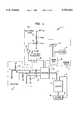
- FIG. 1is a schematic diagram depicting an embodiment of the present invention
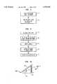
- FIG. 2is a graph depicting an example of a relationship between the amount of gain and hexadecimal value for the gain signal
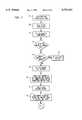
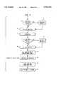
- FIGS. 3 and 4are flowcharts depicting an example of a processing means for transforming the serial stream to simulate a computer mouse
- FIG. 5is a flowchart depicting an example of a sig -- alarm routine that executes upon the occurrence of an interrupt
- FIG. 6is a flowchart depicting an example of a mouse routine for the Logitek® mouse referenced in FIGS. 3 and 4;
- FIGS. 7, 8 and 9are the flowcharts depicted in FIGS. 3 and 4 with embedded alarms routine.
- FIG. 10is a side view of a foot pedal mechanism for varying the gain signal from the gain control device in FIG. 1.
- a hands-free mouse unit 02is connected via a serial line 06 to a first serial port 14 in a computer 04.
- the hands-free mouse unit 02transmits cursor position signals to the computer 04 and comprises a pointing device 20, a gain control device 30, a plurality of pushbuttons 40 and a processor 50.
- the hands-free mouse unit 02transmits signals which are subsequently converted by a processing means within the computer 04 in a form simulating a mouse output and later transmitted by the processing means to a mouse port 16 in a keyboard 10 connected to the computer 04 where it is subsequently processed by a mouse driver program.
- the pointing device 20can be any number of products that provides coordinate input signals indicating an amount of movement along the y-axis and along the x-axis in response to physical movement of the pointing device 20. Note that some pointing devices 20 provides coordinate input signals indicating changes in pitch (i.e., elevation) and yaw (i.e., azimuth) which may be converted to a corresponding amount of movement along the y-axis and x-axis. Typical of pointing devices are mice, track balls, moles, eye-tracking technology, joysticks and position trackers, such as mechanical, optical, magnetic and acoustic. Such devices and their technology are well known in the art.
- the pointing device 20 employedis an alternating current magnetic position tracker manufactured by Polhemus called 3Space® Isotrak®.
- the 3Space® Isotrak®comprises a source 22, a sensor 24 and a control unit 26.
- the source 22is constructed of three mutually perpendicular emitter coils, not shown, that generate three perpendicular rotating magnetic fields.
- the sensor 24is constructed of three mutually perpendicular sensor coils, not shown.
- the three magnetic fields generated from the source 22induce three currents in each of the sensor coils.
- the current induced in each sensor coilwill vary depending on its distance and angle from the source 22. This provides a basis for the control unit 26 to calculate relative pitch and yaw values.
- the pitch and yaw valuesare then used to calculate a corresponding amount of movement by the 3Space® Isotrak® along the y-axis and x-axis, respectively.
- the calculation processcomprises the following steps: (1) determining ⁇ pitch and ⁇ yaw, which are the difference between a first and second set of pitch and yaw values, respectively; and (2) multiplying the sine function for ⁇ pitch and ⁇ yaw against a predetermined distance D (i.e., the distance the sensor 24 is assumed to be from a computer monitor, not shown).
- Di.e., the distance the sensor 24 is assumed to be from a computer monitor, not shown.
- the present inventionincludes a gain control device 30.
- Gainis defined as the ratio of cursor movement along the y-axis and x-axis relative to the corresponding amount of movement by the pointing device 20 along the y-axis and x-axis.
- the gain control device 30includes, but is not limited to, one of the following devices that permits users to manipulate the magnitude of a gain signal: an optical shaft encoder; an accelerometer; an electrolytic inclinometer; a pressure gauge; a strain gauge; a photocell and light source that are moved together or apart.
- One embodiment of the gain control device 30comprises the following electrical components coupled in series: power supply 32 to fixed resistor 34 to variable resistor 36 to buffer amplifier 38 to analog/digital converter 39.
- the gain control device 30outputs to the processor 50 a voltage signal in binary digit form.
- the voltage signalis used as the gain signal.
- the buffer amplifier 38is designed with a high input impedance and low output impedance to minimize the load on the variable voltage and to provide ample "drive" for the analog/digital converter 39.
- the buffer amplifier 38transforms the voltage signal into a low input impedance for the analog/digital converter 39 where it is subsequently output in binary digit form to the processor 50 and later used for calculating a gain value.
- the preferred embodiment of the inventionutilizes a foot pedal mechanism 37, as shown in FIG. 10, to vary the impedance of the variable resistor 36 for hands-free operation.
- the foot pedal mechanism 37comprises an upper portion 37a, a lower portion 37b, a spring 37c and a hinge 37d.
- the upper portion 37a and lower portion 37bare hinged to each other at or near point A by the hinge 37d and are separated at point B by the spring 37c, which is interposed between the upper portion 37a and lower portion 37b, allowing the foot pedal mechanism 37 to move between an up and down position.
- the variable resistor 36is positioned within the foot pedal mechanism 37 in a manner permitting the user to vary the resistance of the variable resistor 36 by manipulating the foot pedal mechanism 37 between the up and down position.
- the gain control device 30permits users to swiftly manipulate the gain of the pointing device 20 so small movements may be easily performed by lowering the gain and fast movements can be quickly accomplished by raising the gain.
- the resistance of the variable resistor 36can be varied using the foot pedal mechanism 37. For each position of the foot pedal mechanism 37, there is an associate gain signal. Depressing the foot pedal mechanism 37 increases the resistance and causes an increased gain signal to be transmitted.
- the relationship between the gain value and the gain signal(expressed in hexadecimal notation from the analog/digital converter 39) is piecewise linear, as shown in FIG. 2. Other relationships may also be applied. Slight depression of the foot pedal mechanism 37 allows the user to decrease the gain and enhance cursor positioning precision. This compensates for users with poor motor skills.
- Increased depression of the foot pedal mechanism 37increases the gain allowing the user to re-position the cursor larger distances quickly with smaller movements of the pointing device 20. This is particularly advantageous for users having a limited range of motion with the body part which operates the pointing device 20. Most users use large gain and small gain settings depending on the amount of movement desired.
- FIG. 2provides the gain control device 30 with a "clutch” function for re-centering operations.
- the "clutch” functionis akin to picking a conventional computer mouse off the surface and re-centering it without changing the position of the cursor. This gives the user freedom to move the pointing device 20 without re-positioning the cursor.
- the "clutch” functionis accomplished by assigning a gain value of zero to a range of hexadecimal values less than or equal to a predetermined value. This predetermined hexadecimal value is referred to as "minped.” As shown in FIG. 2, "minped" is equal to hexadecimal value "0f.”
- the present inventionincludes the pushbuttons 40 for supplying various instructions with respect to the current position of the cursor.
- the pushbuttons 40are interposed between power supplies 44 and parallel ports 42 of the processor 50 and comprise a resistor 46 and a switch 48 having a positive "on” and a positive “off” position.
- the switch 48remains in the positive "on” position unless depressed by the user.
- a voltageapproximately 5 volts
- a voltageapproximately 5 volts
- approximately zero voltageis transmitted.
- keyboard buttons or verbal buttonscould be used to perform the functions of the pushbuttons 40.
- the signals transmitted from the pushbuttons 40, control unit 26 and analog/digital converter 39have associated values and are stored in the processor 50 until they are retrieved by the computer 04.
- the present inventionincludes a processing means within the computer 04 operative to execute a program stored in associated memory for retrieving the aforementioned values and then outputting them in the form of a byte array simulating a mouse output.
- FIGS. 3, 4 and 6are flowcharts illustrating such a processing means.
- FIGS. 3 and 4represent a flowchart of a main routine and
- FIG. 6represents a flowchart of a subroutine called by the main routine.
- the main routinebegins by declaring definitions and storage allocations in step 3a and initializing both serial lines 06 and 08 in step 3b.
- Step 3cmarks the beginning of a loop which continuously processes information from the processor 50. This loop executes approximately twenty times per second.
- the routinetransmits a "read" command to the processor 50 and retrieves the current pushbuttons 40 byte values and analog/digital converter 39 hexadecimal value. The current byte and hexadecimal values are saved as "buttons" and "pedal,” respectively, in step 3e.
- Step 3fchecks to determine whether the position of pushbuttons 40 have changed since the last execution of the loop by comparing "buttons" to "sbuttons,” i.e., previously saved byte values for the pushbuttons 40, and whether the pushbuttons 40 are currently depressed.
- the value “sbuttons”were initially set to zero in step 3a. If (1) either “buttons” differs from “sbuttons” or “buttons” do not equal zero and (2) if "pedal” is less than or equal to "minped” (which was set in step 3a), then the routine proceeds to step 3g and calls the mouse routine depicted in FIG. 6 to output the byte value as if it was transmitted by a mouse. If either conditions are false, the main routine continues to step 3h.
- the mouse routineIn the mouse routine, the contents of "buttons" will be input into a byte array.
- the mouse routine depicted in FIG. 6outputs a byte array simulating a Logitek® mouse output. It should be understood that other brands of mice could just as easily have been simulated.
- the mouse routinebegins with initialization of the byte array in step 6a. Step 6b proceeds to input the contents of "buttons” into the byte array depending on which pushbuttons 40 were pushed. The mouse routine continues to step 6c where it inputs the values for ⁇ y and ⁇ x. Unless the mouse routine was called by step 4l, the values for both ⁇ y and ⁇ x would be zero.
- Step 6doutputs the byte array to the computer 04 through the mouse port 16 where the byte array is processed the mouse driver. Control is then returned to the calling routine. Step 3h proceeds to update "sbuttons" with the contents in "buttons” for future reference.
- step 3ia "read" command is transmitted to the processor 50 to retrieve the current values for pitch and yaw.
- step 4areformats and sign extends the current pitch and yaw signals as "cpitch” and "cyaw.”
- Step 4bdecides whether any action must be performed with the computer cursor based on these values. If “pedal” is less than or equal to “minped,” the routine assumes the user is performing re-centering operations and goes to step 4c so it can update the previously saved pitch and yaw values, i.e., "spitch” and “syaw,” respectively, with its current values for future reference. The routine is then returned to the beginning of the loop at step 3c. Otherwise “pedal” is greater than “minped” and the routine assumes the user is re-positioning the cursor and proceeds to step 4d.
- Step 4dfirst determines the gain value based on the hexadecimal value of "pedal" and a predetermined relationship between the two values. An example of such a relationship is illustrated in FIG. 2. Step 4d then proceeds to calculate ⁇ y for the computer cursor.
- the value ⁇ y (or ⁇ x)represents the scaled amount of relative movement along the y-axis (or x-axis).
- This valueis determined by calculating ⁇ pitch, i.e., difference between "cpitch” and “spitch” (or ⁇ yaw, i.e., difference between “cyaw” and “syaw”), converting ⁇ pitch (or ⁇ yaw) to a corresponding amount of movement along the y-axis (or x-axis) and using the gain value to scale the amount of movement.
- ⁇ pitchi.e., difference between "cpitch” and "spitch” (or ⁇ yaw, i.e., difference between "cyaw” and “syaw”
- ⁇ pitchor ⁇ yaw
- One embodiment of the routineincludes a low pass filter routine for correcting the "noise" problem and stabilizing the computer cursor by using the average value of ⁇ y instead of the current ⁇ y value. This will stabilize the movement of the computer cursor.
- Step 4dfirst determines whether the user opted to employ the low pass filter routine. If yes, the routine goes to step 4f which calculates an average ⁇ y based on the current ⁇ y and a predetermined number of prior ⁇ y's. The average ⁇ y value will be used to re-position the cursor. The routine continues to step 4g where it sets the maximum ⁇ y, as required by the operating system. Steps 4h-k calculates ⁇ x for the computer cursor in the same manner steps 4d-g calculates ⁇ y.
- step 4lUpon calculating ⁇ y and ⁇ x (or average ⁇ y and ⁇ x), step 4l calls the mouse routine.
- the values for ⁇ y and ⁇ xare input into the byte array in step 6c and then output to the mouse port 16 by step 6d causing the cursor to be re-positioned.
- Controlis returned to the main routine where step 4m updates "spitch" and "syaw” with the contents of "cpitch" and "cyaw.”
- the routineis subsequently looped back to step 3c where it can process the next set of signals from the processor 50.
- FIGS. 7-9One such embodiment is shown in FIGS. 7-9.
- This embodimentutilizes system calls and is executable in an UNIX® operating system.
- the time-out alarmoperates on the principle that the "read" command must be completed within a specified time interval otherwise a system alarm will cause an interrupt to occur.
- a series of programming statementsUpon occurrence of the interrupt, a series of programming statements will notify the routine that the time-out alarm had expired. The serial lines 06 and 08 will then be closed and the main routine restarted.
- Step 7abegins by initializing the time-out alarm. It instructs the operating system that the routine "sig -- alarm,” as shown in FIG. 5, is the routine to execute in the event of an interrupt.
- Step 7bproceeds to check whether the time-out alarm expired by using "setjmp" to save its stack environment in “read -- alarm” for later use by "longjmp". A value of "0" is always returned in the initial loop. As long as the returned value remains “0" and is not changed by the "sig -- alarm” routine, the time-out alarm is deemed not expired.
- step 7dsets the system alarm to lapse after a predetermined time interval. If step 3g is timely completed, the routine continues to step 7d where the system alarm is cancelled before the interrupt can occur. Otherwise the system alarm would cause an interrupt.
- Step 5a of the "sig -- alarm” routineuses “longjmp” to restore the environment saved in “read -- alarm” by the last call of "setjmp.” It then causes execution to continue as if the call of "setjmp" had just returned a value of "1.”
- step 7blater checks the returned value, it will read “1" and conclude the time-out alarm expired. In such an event, the routine proceeds to step 7c and goes to the restart routine in FIG. 9.
- steps 9a and 9b of the restart routinethe first and second serial lines 06 and 08 are closed and then the main routine is restarted.
- steps 8a-dare identical in function to steps 7b-e and are used to confirm successful "read" commands for pitch and yaw values in step 3i.
- the above described processing meansis within the processor 50 and the byte array is outputted directly to the mouse port 16 or computer 04.
Landscapes
- Engineering & Computer Science (AREA)
- General Engineering & Computer Science (AREA)
- Theoretical Computer Science (AREA)
- Human Computer Interaction (AREA)
- Physics & Mathematics (AREA)
- General Physics & Mathematics (AREA)
- Position Input By Displaying (AREA)
Abstract
Description
Claims (18)
Priority Applications (5)
| Application Number | Priority Date | Filing Date | Title |
|---|---|---|---|
| US08/438,323US5793354A (en) | 1995-05-10 | 1995-05-10 | Method and apparatus for an improved computer pointing device |
| CA002174687ACA2174687A1 (en) | 1995-05-10 | 1996-04-22 | Method and apparatus for an improved computer pointing device |
| EP96303086AEP0742510A3 (en) | 1995-05-10 | 1996-05-01 | Method and apparatus for a computer pointing device |
| MXPA/A/1996/001652AMXPA96001652A (en) | 1995-05-10 | 1996-05-03 | Method and apparatus for improved positioning device for computed |
| JP8115947AJPH096537A (en) | 1995-05-10 | 1996-05-10 | Peripheral device of computer |
Applications Claiming Priority (1)
| Application Number | Priority Date | Filing Date | Title |
|---|---|---|---|
| US08/438,323US5793354A (en) | 1995-05-10 | 1995-05-10 | Method and apparatus for an improved computer pointing device |
Publications (1)
| Publication Number | Publication Date |
|---|---|
| US5793354Atrue US5793354A (en) | 1998-08-11 |
Family
ID=23740205
Family Applications (1)
| Application Number | Title | Priority Date | Filing Date |
|---|---|---|---|
| US08/438,323Expired - Fee RelatedUS5793354A (en) | 1995-05-10 | 1995-05-10 | Method and apparatus for an improved computer pointing device |
Country Status (4)
| Country | Link |
|---|---|
| US (1) | US5793354A (en) |
| EP (1) | EP0742510A3 (en) |
| JP (1) | JPH096537A (en) |
| CA (1) | CA2174687A1 (en) |
Cited By (14)
| Publication number | Priority date | Publication date | Assignee | Title |
|---|---|---|---|---|
| US6049326A (en)* | 1997-05-12 | 2000-04-11 | Siemens Information And Communication Networks, Inc. | System and method for dual browser modes |
| US6219027B1 (en)* | 1997-01-17 | 2001-04-17 | Fujitsu Limited | Image display system with intelligent pointer displaying capability |
| US6388655B1 (en) | 1999-11-08 | 2002-05-14 | Wing-Keung Leung | Method of touch control of an input device and such a device |
| US20050030279A1 (en)* | 2003-08-08 | 2005-02-10 | Liang Fu | Multi-functional pointing and control device |
| US20050270494A1 (en)* | 2004-05-28 | 2005-12-08 | Banning Erik J | Easily deployable interactive direct-pointing system and presentation control system and calibration method therefor |
| US20070013657A1 (en)* | 2005-07-13 | 2007-01-18 | Banning Erik J | Easily deployable interactive direct-pointing system and calibration method therefor |
| US20080055275A1 (en)* | 2006-08-30 | 2008-03-06 | Timothy James Orsley | Optical sensing in displacement type input apparatus and methods |
| WO2007109286A3 (en)* | 2006-03-20 | 2008-04-24 | Sandio Technology Corp | Updating resolution of pointing devices |
| US20090281664A1 (en)* | 2008-05-06 | 2009-11-12 | Hurco Companies, Inc. | Mouse-Based Hand Wheel Control For a Machine Tool |
| US20100179428A1 (en)* | 2008-03-17 | 2010-07-15 | Worcester Polytechnic Institute | Virtual interactive system for ultrasound training |
| CN101611369B (en)* | 2007-11-26 | 2012-08-22 | 索尼株式会社 | Input device, control device, control system, control method and handheld device |
| US9265458B2 (en) | 2012-12-04 | 2016-02-23 | Sync-Think, Inc. | Application of smooth pursuit cognitive testing paradigms to clinical drug development |
| US9380976B2 (en) | 2013-03-11 | 2016-07-05 | Sync-Think, Inc. | Optical neuroinformatics |
| US10359868B2 (en)* | 2012-10-29 | 2019-07-23 | Pixart Imaging Incorporation | Method and apparatus for controlling object movement on screen |
Families Citing this family (4)
| Publication number | Priority date | Publication date | Assignee | Title |
|---|---|---|---|---|
| US20050215321A1 (en)* | 2004-03-29 | 2005-09-29 | Saied Hussaini | Video game controller with integrated trackball control device |
| DE102005057143A1 (en) | 2005-11-30 | 2007-06-06 | BSH Bosch und Siemens Hausgeräte GmbH | Refrigeration unit with insulation strip for thermal decoupling of the side walls |
| EP1860529A1 (en)* | 2006-05-24 | 2007-11-28 | Stmicroelectronics Sa | Mouse with variable gain |
| FR2911996A1 (en) | 2007-01-31 | 2008-08-01 | St Microelectronics Sa | Electronic integrated circuit, has protection elements discharging nodes, respectively, where element does not allow circulation of electric current towards or from nodes when circuit is subjected to voltage, respectively |
Citations (9)
| Publication number | Priority date | Publication date | Assignee | Title |
|---|---|---|---|---|
| US5012231A (en)* | 1988-12-20 | 1991-04-30 | Golemics, Inc. | Method and apparatus for cursor motion having variable response |
| US5148152A (en)* | 1991-01-11 | 1992-09-15 | Stueckle Duane H | Foot pedal control mechanism for computers |
| US5191641A (en)* | 1988-09-26 | 1993-03-02 | Sharp Kabushiki Kaisha | Cursor shift speed control system |
| US5195179A (en)* | 1986-01-29 | 1993-03-16 | Hitachi, Ltd. | Coordinate input apparatus |
| US5334997A (en)* | 1992-12-22 | 1994-08-02 | David Scallon | Foot-operated computer control |
| US5360971A (en)* | 1992-03-31 | 1994-11-01 | The Research Foundation State University Of New York | Apparatus and method for eye tracking interface |
| US5367315A (en)* | 1990-11-15 | 1994-11-22 | Eyetech Corporation | Method and apparatus for controlling cursor movement |
| US5398044A (en)* | 1992-12-11 | 1995-03-14 | Icl Personal Systems Oy | Method of and an arrangement for controlling the cursor movement on a graphical display |
| US5477236A (en)* | 1987-03-20 | 1995-12-19 | Hitachi, Ltd. | Method and apparatus for controlling movement of cursor |
Family Cites Families (4)
| Publication number | Priority date | Publication date | Assignee | Title |
|---|---|---|---|---|
| EP0362255B1 (en)* | 1987-05-01 | 1993-07-14 | General DataComm, Inc. | System and apparatus for providing three dimensions of input to a host processor |
| NL8800450A (en)* | 1988-02-23 | 1989-09-18 | Philips Nv | WORKSTATION WITH CONTINUOUSLY VARIABLE SENSITIVITY ADJUSTMENT OF THE POSITION CONTROL. |
| US5376946A (en)* | 1991-07-08 | 1994-12-27 | Mikan; Peter J. | Computer mouse simulator device |
| US5323174A (en)* | 1992-12-02 | 1994-06-21 | Matthew H. Klapman | Device for determining an orientation of at least a portion of a living body |
- 1995
- 1995-05-10USUS08/438,323patent/US5793354A/ennot_activeExpired - Fee Related
- 1996
- 1996-04-22CACA002174687Apatent/CA2174687A1/ennot_activeAbandoned
- 1996-05-01EPEP96303086Apatent/EP0742510A3/ennot_activeWithdrawn
- 1996-05-10JPJP8115947Apatent/JPH096537A/ennot_activeWithdrawn
Patent Citations (9)
| Publication number | Priority date | Publication date | Assignee | Title |
|---|---|---|---|---|
| US5195179A (en)* | 1986-01-29 | 1993-03-16 | Hitachi, Ltd. | Coordinate input apparatus |
| US5477236A (en)* | 1987-03-20 | 1995-12-19 | Hitachi, Ltd. | Method and apparatus for controlling movement of cursor |
| US5191641A (en)* | 1988-09-26 | 1993-03-02 | Sharp Kabushiki Kaisha | Cursor shift speed control system |
| US5012231A (en)* | 1988-12-20 | 1991-04-30 | Golemics, Inc. | Method and apparatus for cursor motion having variable response |
| US5367315A (en)* | 1990-11-15 | 1994-11-22 | Eyetech Corporation | Method and apparatus for controlling cursor movement |
| US5148152A (en)* | 1991-01-11 | 1992-09-15 | Stueckle Duane H | Foot pedal control mechanism for computers |
| US5360971A (en)* | 1992-03-31 | 1994-11-01 | The Research Foundation State University Of New York | Apparatus and method for eye tracking interface |
| US5398044A (en)* | 1992-12-11 | 1995-03-14 | Icl Personal Systems Oy | Method of and an arrangement for controlling the cursor movement on a graphical display |
| US5334997A (en)* | 1992-12-22 | 1994-08-02 | David Scallon | Foot-operated computer control |
Non-Patent Citations (2)
| Title |
|---|
| "Isotrak II" Polhemus, pp. 1-3, Sep. 1996. |
| Isotrak II Polhemus, pp. 1 3, Sep. 1996.* |
Cited By (31)
| Publication number | Priority date | Publication date | Assignee | Title |
|---|---|---|---|---|
| US6219027B1 (en)* | 1997-01-17 | 2001-04-17 | Fujitsu Limited | Image display system with intelligent pointer displaying capability |
| US6049326A (en)* | 1997-05-12 | 2000-04-11 | Siemens Information And Communication Networks, Inc. | System and method for dual browser modes |
| US6388655B1 (en) | 1999-11-08 | 2002-05-14 | Wing-Keung Leung | Method of touch control of an input device and such a device |
| US20050030279A1 (en)* | 2003-08-08 | 2005-02-10 | Liang Fu | Multi-functional pointing and control device |
| US8866742B2 (en) | 2004-05-28 | 2014-10-21 | Ultimatepointer, Llc | Easily deployable interactive direct-pointing system and presentation control system and calibration method therefor |
| US8049729B2 (en) | 2004-05-28 | 2011-11-01 | Erik Jan Banning | Easily deployable interactive direct-pointing system and presentation control system and calibration method therefor |
| US9785255B2 (en) | 2004-05-28 | 2017-10-10 | UltimatePointer, L.L.C. | Apparatus for controlling contents of a computer-generated image using three dimensional measurements |
| US20050270494A1 (en)* | 2004-05-28 | 2005-12-08 | Banning Erik J | Easily deployable interactive direct-pointing system and presentation control system and calibration method therefor |
| US11755127B2 (en) | 2004-05-28 | 2023-09-12 | UltimatePointer, L.L.C. | Multi-sensor device with an accelerometer for enabling user interaction through sound or image |
| US7746321B2 (en) | 2004-05-28 | 2010-06-29 | Erik Jan Banning | Easily deployable interactive direct-pointing system and presentation control system and calibration method therefor |
| US11416084B2 (en) | 2004-05-28 | 2022-08-16 | UltimatePointer, L.L.C. | Multi-sensor device with an accelerometer for enabling user interaction through sound or image |
| US20100283732A1 (en)* | 2004-05-28 | 2010-11-11 | Erik Jan Banning | Easily deployable interactive direct-pointing system and presentation control system and calibration method therefor |
| US11409376B2 (en) | 2004-05-28 | 2022-08-09 | UltimatePointer, L.L.C. | Multi-sensor device with an accelerometer for enabling user interaction through sound or image |
| US11073919B2 (en) | 2004-05-28 | 2021-07-27 | UltimatePointer, L.L.C. | Multi-sensor device with an accelerometer for enabling user interaction through sound or image |
| US11402927B2 (en) | 2004-05-28 | 2022-08-02 | UltimatePointer, L.L.C. | Pointing device |
| US9411437B2 (en) | 2004-05-28 | 2016-08-09 | UltimatePointer, L.L.C. | Easily deployable interactive direct-pointing system and presentation control system and calibration method therefor |
| US9063586B2 (en) | 2004-05-28 | 2015-06-23 | Ultimatepointer, Llc | Easily deployable interactive direct-pointing system and presentation control system and calibration method therefor |
| US20070013657A1 (en)* | 2005-07-13 | 2007-01-18 | Banning Erik J | Easily deployable interactive direct-pointing system and calibration method therefor |
| US10372237B2 (en) | 2005-07-13 | 2019-08-06 | UltimatePointer, L.L.C. | Apparatus for controlling contents of a computer-generated image using 3D measurements |
| US9285897B2 (en) | 2005-07-13 | 2016-03-15 | Ultimate Pointer, L.L.C. | Easily deployable interactive direct-pointing system and calibration method therefor |
| US11841997B2 (en) | 2005-07-13 | 2023-12-12 | UltimatePointer, L.L.C. | Apparatus for controlling contents of a computer-generated image using 3D measurements |
| WO2007109286A3 (en)* | 2006-03-20 | 2008-04-24 | Sandio Technology Corp | Updating resolution of pointing devices |
| US9141230B2 (en)* | 2006-08-30 | 2015-09-22 | Avaoo Technologies General IP (Singapore) Pte. Ltd. | Optical sensing in displacement type input apparatus and methods |
| US20080055275A1 (en)* | 2006-08-30 | 2008-03-06 | Timothy James Orsley | Optical sensing in displacement type input apparatus and methods |
| CN101611369B (en)* | 2007-11-26 | 2012-08-22 | 索尼株式会社 | Input device, control device, control system, control method and handheld device |
| US20100179428A1 (en)* | 2008-03-17 | 2010-07-15 | Worcester Polytechnic Institute | Virtual interactive system for ultrasound training |
| US8041448B2 (en)* | 2008-05-06 | 2011-10-18 | Hurco Companies, Inc. | Mouse-based hand wheel control for a machine tool |
| US20090281664A1 (en)* | 2008-05-06 | 2009-11-12 | Hurco Companies, Inc. | Mouse-Based Hand Wheel Control For a Machine Tool |
| US10359868B2 (en)* | 2012-10-29 | 2019-07-23 | Pixart Imaging Incorporation | Method and apparatus for controlling object movement on screen |
| US9265458B2 (en) | 2012-12-04 | 2016-02-23 | Sync-Think, Inc. | Application of smooth pursuit cognitive testing paradigms to clinical drug development |
| US9380976B2 (en) | 2013-03-11 | 2016-07-05 | Sync-Think, Inc. | Optical neuroinformatics |
Also Published As
| Publication number | Publication date |
|---|---|
| CA2174687A1 (en) | 1996-11-11 |
| EP0742510A3 (en) | 1997-08-27 |
| MX9601652A (en) | 1997-07-31 |
| JPH096537A (en) | 1997-01-10 |
| EP0742510A2 (en) | 1996-11-13 |
Similar Documents
| Publication | Publication Date | Title |
|---|---|---|
| US5793354A (en) | Method and apparatus for an improved computer pointing device | |
| US6124845A (en) | Coordinate input device | |
| US10234944B2 (en) | Force feedback system including multi-tasking graphical host environment | |
| US6937227B2 (en) | Hand-held pointing device | |
| CN103294177B (en) | cursor movement control method and system | |
| US6598978B2 (en) | Image display system, image display method, storage medium, and computer program | |
| AU2002329982B2 (en) | Improved wireless control device | |
| US5581484A (en) | Finger mounted computer input device | |
| US5875257A (en) | Apparatus for controlling continuous behavior through hand and arm gestures | |
| US20140109025A1 (en) | High parameter-count touch-pad controller | |
| US20050122313A1 (en) | Versatile, configurable keyboard | |
| US5124689A (en) | Integrated keyboard and pointing device system | |
| JPH08305488A (en) | Method and apparatus for generation of direction and force vector in input device | |
| JPH08115153A (en) | Parameter input device | |
| JPH08212009A (en) | Graphics display pointer by integrated selection | |
| US6452587B1 (en) | Cursor controller using speed position | |
| JPH08221201A (en) | Touch panel coordinate operating method and information processor using the method | |
| JP4590596B2 (en) | INPUT DEVICE, CONTROL DEVICE, INPUT METHOD, CONTROL METHOD, AND PROGRAM | |
| WO1997035277A1 (en) | Foot-operated cursor controller | |
| MXPA96001652A (en) | Method and apparatus for improved positioning device for computed | |
| KR20030028023A (en) | Method of inputting letter using mouse and its system | |
| JPH09179687A (en) | Coordinate input device using pointing device and cursor movement control method thereof | |
| JP2019061542A (en) | Parameter control device, electronic musical instrument, parameter control method and control program | |
| EP0752639A1 (en) | Chordic keyboard with integral mouse | |
| JPS6125232A (en) | input device |
Legal Events
| Date | Code | Title | Description |
|---|---|---|---|
| AS | Assignment | Owner name:AT&T IPM CORP., FLORIDA Free format text:ASSIGNMENT OF ASSIGNORS INTEREST;ASSIGNOR:KAPLAN, ALAN EDWARD;REEL/FRAME:007610/0603 Effective date:19950424 | |
| AS | Assignment | Owner name:THE CHASE MANHATTAN BANK, AS COLLATERAL AGENT, TEX Free format text:CONDITIONAL ASSIGNMENT OF AND SECURITY INTEREST IN PATENT RIGHTS;ASSIGNOR:LUCENT TECHNOLOGIES INC. (DE CORPORATION);REEL/FRAME:011722/0048 Effective date:20010222 | |
| FEPP | Fee payment procedure | Free format text:PAYOR NUMBER ASSIGNED (ORIGINAL EVENT CODE: ASPN); ENTITY STATUS OF PATENT OWNER: LARGE ENTITY | |
| FPAY | Fee payment | Year of fee payment:4 | |
| FPAY | Fee payment | Year of fee payment:8 | |
| AS | Assignment | Owner name:LUCENT TECHNOLOGIES INC., NEW JERSEY Free format text:TERMINATION AND RELEASE OF SECURITY INTEREST IN PATENT RIGHTS;ASSIGNOR:JPMORGAN CHASE BANK, N.A. (FORMERLY KNOWN AS THE CHASE MANHATTAN BANK), AS ADMINISTRATIVE AGENT;REEL/FRAME:018584/0446 Effective date:20061130 | |
| FEPP | Fee payment procedure | Free format text:PAYOR NUMBER ASSIGNED (ORIGINAL EVENT CODE: ASPN); ENTITY STATUS OF PATENT OWNER: LARGE ENTITY Free format text:PAYER NUMBER DE-ASSIGNED (ORIGINAL EVENT CODE: RMPN); ENTITY STATUS OF PATENT OWNER: LARGE ENTITY | |
| REMI | Maintenance fee reminder mailed | ||
| LAPS | Lapse for failure to pay maintenance fees | ||
| STCH | Information on status: patent discontinuation | Free format text:PATENT EXPIRED DUE TO NONPAYMENT OF MAINTENANCE FEES UNDER 37 CFR 1.362 | |
| FP | Lapsed due to failure to pay maintenance fee | Effective date:20100811 |