US5793334A - Shrouded horn feed assembly - Google Patents
Shrouded horn feed assemblyDownload PDFInfo
- Publication number
- US5793334A US5793334AUS08/698,234US69823496AUS5793334AUS 5793334 AUS5793334 AUS 5793334AUS 69823496 AUS69823496 AUS 69823496AUS 5793334 AUS5793334 AUS 5793334A
- Authority
- US
- United States
- Prior art keywords
- feed waveguide
- horn
- waveguide
- feed
- radiating aperture
- Prior art date
- Legal status (The legal status is an assumption and is not a legal conclusion. Google has not performed a legal analysis and makes no representation as to the accuracy of the status listed.)
- Expired - Lifetime
Links
- 230000005855radiationEffects0.000claimsabstractdescription90
- 230000003595spectral effectEffects0.000claimsdescription16
- 239000003989dielectric materialSubstances0.000claimsdescription6
- 230000002401inhibitory effectEffects0.000claims13
- 230000007704transitionEffects0.000abstractdescription8
- 238000011161developmentMethods0.000abstractdescription2
- 238000007493shaping processMethods0.000abstractdescription2
- 238000004891communicationMethods0.000description15
- 230000005540biological transmissionEffects0.000description13
- 230000010287polarizationEffects0.000description13
- 238000010276constructionMethods0.000description12
- 239000004020conductorSubstances0.000description9
- 230000005684electric fieldEffects0.000description6
- 230000001902propagating effectEffects0.000description6
- 230000008859changeEffects0.000description5
- 230000008878couplingEffects0.000description4
- 238000010168coupling processMethods0.000description4
- 238000005859coupling reactionMethods0.000description4
- 230000000694effectsEffects0.000description4
- 238000001228spectrumMethods0.000description4
- 230000015572biosynthetic processEffects0.000description3
- 230000007423decreaseEffects0.000description3
- 230000006870functionEffects0.000description3
- 229920003023plasticPolymers0.000description3
- 230000008054signal transmissionEffects0.000description3
- 239000013598vectorSubstances0.000description3
- 239000004677NylonSubstances0.000description2
- 230000008901benefitEffects0.000description2
- 239000002131composite materialSubstances0.000description2
- 238000012217deletionMethods0.000description2
- 230000037430deletionEffects0.000description2
- 238000001914filtrationMethods0.000description2
- 239000000463materialSubstances0.000description2
- 229920001778nylonPolymers0.000description2
- 230000010363phase shiftEffects0.000description2
- 239000004033plasticSubstances0.000description2
- 238000012545processingMethods0.000description2
- 230000009467reductionEffects0.000description2
- 230000001360synchronised effectEffects0.000description2
- 239000004809TeflonSubstances0.000description1
- 229920006362Teflon®Polymers0.000description1
- 230000004323axial lengthEffects0.000description1
- 230000009286beneficial effectEffects0.000description1
- 238000006243chemical reactionMethods0.000description1
- 238000005388cross polarizationMethods0.000description1
- 230000003247decreasing effectEffects0.000description1
- 230000018109developmental processEffects0.000description1
- 230000003292diminished effectEffects0.000description1
- 230000006872improvementEffects0.000description1
- 230000003993interactionEffects0.000description1
- 238000000034methodMethods0.000description1
- 238000012986modificationMethods0.000description1
- 230000004048modificationEffects0.000description1
- 229920003223poly(pyromellitimide-1,4-diphenyl ether)Polymers0.000description1
- 230000008569processEffects0.000description1
- 230000000717retained effectEffects0.000description1
- 238000000926separation methodMethods0.000description1
- 238000004904shorteningMethods0.000description1
Images


Classifications
- H—ELECTRICITY
- H01—ELECTRIC ELEMENTS
- H01Q—ANTENNAS, i.e. RADIO AERIALS
- H01Q19/00—Combinations of primary active antenna elements and units with secondary devices, e.g. with quasi-optical devices, for giving the antenna a desired directional characteristic
- H01Q19/06—Combinations of primary active antenna elements and units with secondary devices, e.g. with quasi-optical devices, for giving the antenna a desired directional characteristic using refracting or diffracting devices, e.g. lens
- H01Q19/08—Combinations of primary active antenna elements and units with secondary devices, e.g. with quasi-optical devices, for giving the antenna a desired directional characteristic using refracting or diffracting devices, e.g. lens for modifying the radiation pattern of a radiating horn in which it is located
- H—ELECTRICITY
- H01—ELECTRIC ELEMENTS
- H01Q—ANTENNAS, i.e. RADIO AERIALS
- H01Q13/00—Waveguide horns or mouths; Slot antennas; Leaky-waveguide antennas; Equivalent structures causing radiation along the transmission path of a guided wave
- H01Q13/02—Waveguide horns
- H—ELECTRICITY
- H01—ELECTRIC ELEMENTS
- H01Q—ANTENNAS, i.e. RADIO AERIALS
- H01Q25/00—Antennas or antenna systems providing at least two radiating patterns
- H01Q25/04—Multimode antennas
- H—ELECTRICITY
- H01—ELECTRIC ELEMENTS
- H01Q—ANTENNAS, i.e. RADIO AERIALS
- H01Q5/00—Arrangements for simultaneous operation of antennas on two or more different wavebands, e.g. dual-band or multi-band arrangements
- H01Q5/40—Imbricated or interleaved structures; Combined or electromagnetically coupled arrangements, e.g. comprising two or more non-connected fed radiating elements
- H01Q5/45—Imbricated or interleaved structures; Combined or electromagnetically coupled arrangements, e.g. comprising two or more non-connected fed radiating elements using two or more feeds in association with a common reflecting, diffracting or refracting device
- H01Q5/47—Imbricated or interleaved structures; Combined or electromagnetically coupled arrangements, e.g. comprising two or more non-connected fed radiating elements using two or more feeds in association with a common reflecting, diffracting or refracting device with a coaxial arrangement of the feeds
Definitions
- This inventionrelates to a feed system for an antenna and, more particularly, to a composite feed covering two octaves of bandwidth and providing a common phase center for radiations in each of a plurality of signal bands radiated by the feed.
- Various communication systemsemploy more than one frequency band for electromagnetic signals radiated from a transmitting station to receiving station.
- An important example of such a communication systemis a satellite communication system wherein various bands of signals are transmitted between a satellite above the earth (synchronous orbit) and ground stations on the earth.
- Three such bands of interest herein, including C band, X band, and Ku band,extend in total two octaves of the communication frequency spectrum.
- Within each of the bandsthere is frequency space allocated for reception of signals at the satellite and for transmission of signals from the satellite.
- the C banditself extends over approximately an octave, operates at both linear and circular polarizations, and includes a receive sub-band in the range of 3.625-4.200 GHz and a transmit sub-band in the range of 5.850-6.425 GHz.
- the X bandincludes a receive sub-band in the range of 7.250-7.750 GHz (gigahertz), and a transmit sub-band for transmission from the satellite in the range of 7.900-8.400 GHz.
- the Ku bandoperates at both linear and circular polarizations, and includes a receive sub-band from 10.950 to 12.750 GHz, and a transmit sub-band of 14.000-14.500 GHz. Collectively, these frequency bands extend over approximately two octaves of the communications spectrum.
- the use of numerous antennas for communication at various frequency bandsdefeats the purpose of minimization of payload weight.
- the foregoing problemis compounded by the foregoing spectral utilization.
- the C band and the Ku bandare commercial satellite bands which are spaced apart in the spectrum and, therefore, facilitate the filtering of signals in the two bands so as to permit transmission on one band without significant interference with signals on the other band.
- the X bandwhich is a military band in conjunction with the C band.
- the X bandis contiguous to the C band, it is difficult to separate the two bands in a common antenna system and, furthermore, presently available antenna and feed structures are unable to accomplish this task adequately.
- an antenna feed systemwhich, in accordance with the invention, has a composite coaxial feed structure with plural signal input ports for transmission at each of a plurality of frequency bands via a common single point feed with a horn, shroud and tube arrangement which produces a common phase center.
- the Ku band and the X band signalsare transmitted via a central circular waveguide constructed of a metallic electrically conducting tube and located coaxially to a central axis of the feed.
- the C band signalsare transmitted via coaxial waveguides comprising a center waveguide tube as inner conductor, and an outer tubular conductor coaxial to and spaced apart from the inner conductor.
- Radiating openings of the circular waveguide and of the outer coaxial waveguideare located within a common aperture and, together with the horn, constitute the feed assembly.
- the center circular waveguidemay be referred to as the inner feed waveguide
- the outer coaxial waveguidemay be referred to as the outer feed waveguide.
- the feedis employed to illuminate a reflector or subreflector of the antenna for establishing a desired beam pattern; however, the feed may be used without a reflector for directly radiating a beam of radiation.
- the feedmay also be used with an off-set reflector assembly.
- An aspect of the invention which is of particular interest hereinis the capacity to develop and radiate a hybrid circular waveguide mode HE 11 from field components of a circular waveguide excited by a pair of waveguides wherein one of the waveguides, the foregoing inner feed waveguide, lies within an outer one of the waveguides.
- the outer coaxial waveguidecarries a TE 11 mode which propagates toward the end of the central conductor, namely the inner waveguide, to become a TM 11 wave beyond a radiating aperture of the inner waveguide.
- the inner waveguideoperates in a frequency band higher than the band of the signals of the outer waveguide, and operates substantially independently of the signal in the central inner feed waveguide.
- a shroud with corrugations at the outer diameter of the outer waveguide, and a narrowed neck of the inner waveguide, also with corrugations,facilitates coupling of hybrid radiation to outer space as will be described below.
- each of the feed waveguidesis allocated one octave of frequency space. This is accomplished by the foregoing assignment of the signal bandwidths wherein the inner feed waveguide carries the X and the Ku band signals, and the outer feed waveguide carries the C band signals.
- either the commercial Ku band or the military X bandwould be employed. In such case, it is not necessary to couple both of the X and the Ku band signals to the feed system.
- the feed systemis operative to provide simultaneous beams of X and C band radiation. Coupling of X band and Ku band signals to the inner feed waveguide may be accomplished by a switch when it is desired to utilize either the X band or the Ku band signals.
- the X and the Ku bandsmay be operated simultaneously with a coupling device instead of a switch.
- the C band signalsare fed to the outer feed waveguide in a symmetrical pattern about the central axis by use of four waveguides distributed uniformly about the central axis and being inclined relative to the central axis.
- the four waveguidesserve to launch a C band wave in a desired mode of propagation for radiation from the feed horn in conjunction with the radiations of the X and the Ku bands of radiation.
- the assembly of the four waveguidesmay be referred to as a launcher, and each of the four waveguides may be referred to as a launch waveguide.
- An envelope of the configuration of the four waveguides, and of the launcherhas the shape of a cone.
- each of the launch waveguideshas a cross section which is essentially rectangular, having two broad walls connected by narrower sidewalls. The sidewalls are nearly parallel to radii of the cone, and the broad walls are normal to the radii.
- the broad wallsbecome curved with increasingly greater curvature. Also, the waveguides become closer with progression toward the apex until, in the region of the apex, the thin walls which separate the launch waveguides terminate and allow the four launch waveguides to merge to form the outer feed waveguide.
- the launch waveguidesare adapted to provide an octave bandwidth for transmission of the C band signal. This is accomplished by constructing the launch waveguides with ridges extending inwardly from each of the broad walls. Thus, at the base of the cone, each of the launch waveguides has a double ridged cross section.
- the ridgingalso provides the advantage of locking a mode of propagation of the C band signal through each of the launch waveguides. This is important for insuring that the C band waves arriving at the outer feed waveguide have the requisite mode for launching the desired mode of propagation of the wave in the outer feed waveguide.
- the ridgingis not present in the outer feed waveguide in the vicinity of the radiating aperture and, accordingly, the invention provides for a transition from the double ridging to no ridging.
- the transitionbegins at the base region of the launcher and terminates in a region of the outer feed waveguide contiguous to the launcher.
- the ridge of the outer broad wall of each launch waveguidegradually tapers to zero height at the apex of the launcher, at which point there is only one ridge, namely, the ridge of the inner broad wall.
- the inner and the outer ridgesare of equal height in each of the launch waveguides.
- the inner ridgeincreases in height to provide a spacing between the two ridges which decreases to a value, at the apex of the launcher, which is approximately 60-85 percent of the original spacing at the base of the launcher. This leaves, at the junction of the launcher and the outer feed waveguide, a star-shaped array of the four inner ridges with no separating walls.
- tuning ringsmay be slid along the surface of the outer conductor and/or along the surface of the inner conductor to facilitate development of the desired propagation mode with a minimum standing wave ratio, and thereby tune the outer feed waveguide. Other means of tuning may also be employed to minimize the standing wave ratio.
- the outer conductor of the outer waveguide feedtakes the form of a horn having a circular cylindrical shape, and includes a series of step increases in its diameter. The steps are employed in the forming of the desired wave propagation mode in the horn.
- the hornis terminated in a shroud having a diameter of approximately 3/2 midband wavelength of the C band radiation, the shroud diameter being larger than the diameter of the outer feed waveguide by a factor of approximately 3/2.
- the shroudextends forward of the mouth of the outer feed waveguide by approximately one-quarter of the midband wavelength of the C band radiation. The shroud allows the wide band or multi-octave operation and supports the common phase center.
- the inner feed waveguideis terminated by a dielectric rod inserted in the mouth of tube of the inner feed waveguide.
- the diameter of the inner surface of the inner feed waveguidetapers inwardly to a neck having a slight reduction of diameter at the location of contact with the rod.
- the diameter of the inner feed waveguideis greater than the diameter of the neck by a factor of approximately 4/3.
- the neck diameteris approximately at the cut-off frequency of the C band radiation, and aids in attenuating such radiation as may enter into the inner feed waveguide and be reflected back out with a resonance that alters the C band phase and beam pattern.
- the outer surface of the tube of the inner feed waveguideis stepped down in diameter with an encircling reentrant cavity or trough at the location of the rod. This configuration of the outer surface of the tube of the inner feed waveguide aids in control and shaping of the X and Ku band beam patterns.
- the diameter of the horn at the shroud openingis 3.625 inch
- the inside diameter of the tubeis 1.07 inch
- the inside diameter of the neckis 0.85 inch
- the diameter of the hornis greater than the diameter of the inner feed waveguide by a factor of approximately 4/1.
- the ratio of the diameters of the inner and the outer conductors of the coaxial waveguidesis equal approximately to the ratio of the mid-band wavelength of the C band radiation to the wavelength at the center of the X and the Ku bands carried by the inner feed waveguide.
- the rodhas a dielectric constant of approximately 2, and may be fabricated of a plastic material.
- the roddecreases the wavelength of radiation propagating within the rod, by virtue of the increase in dielectric constant, and serves to control beam width in concert with the shroud.
- the rodextends forward of the mouth of the inner feed waveguide, and forward of the horn into the region of the shroud, and is shaped to reduce interaction between the radiations carried by the two feed waveguides.
- the rodhas a forward cylindrical cavity of cylindrical shape and a larger rear cavity of conic shape.
- An aspect of the operation of the feed systemis the deployment of the launch waveguides in opposite launch pairs. It is useful to consider a rear view of the launcher with the central axis being horizontal, it being understood that the feed assembly is operative in any orientation.
- the four launch waveguidespresent the arrangement of an top waveguide, a bottom waveguide, a right waveguide and a left waveguide.
- the top and the bottom waveguidesconstitute one pair of opposite cooperating launch waveguides
- the right and the left waveguidesconstitute the second pair of opposite cooperating launch waveguides.
- the transmitted signalshave an equal cophasal relationship which is carried forward to the apex of the launcher.
- the electric fieldsare oriented in the vertical direction in both of the top and the bottom waveguides, and the magnetic fields circulate in a common direction about a common vertical axis.
- the electric fieldsare oriented in the horizontal direction in both of the left and the right waveguides, and the magnetic fields circulate in a common direction about a common horizontal axis.
- the magnetic fields of either pair of launch waveguideshave the requisite directions for launching a balanced coaxial mode of an RF (radio frequency) wave in the outer feed waveguide.
- the signals of both pairs of launch waveguidesmay be synchronized with a quadrature relationship to produce a circular polarization within the outer feed waveguide.
- each of the launch waveguidesthere is a TE 11 mode.
- the outer waveguide feedthere is a TE 11 coaxial mode wave for each of the opposite pairs of launch waveguides.
- the operation of the star and other components of the outer feed waveguideare operative to generate the foregoing TE 11 mode and to inhibit formation of other modes of propagation, such as TEM or TE 21 coaxial modes.
- mode conversionstake place with the effect of exciting the circular TE 11 and TM 11 modes.
- a combination of these modesconstitutes an HE 11 -like hybrid mode which produces the circular radiation pattern desired for the system.
- FIG. 1is a stylized view of satellites above the earth for communication with ground stations;
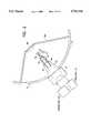
- FIG. 2is a diagrammatic view of a feed system incorporated within each of the ground antenna stations, a portion of the feed being cut away to show the location of a waveguide system of the feed;
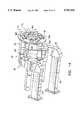
- FIG. 3is a diagrammatic view of a feed of the antenna of FIG. 2, the feed embodying the invention, and the view being partially cut away to show interior portions of the feed;
- FIG. 4is a side view of the feed
- FIG. 5is a front end view taken along the line 5--5 in FIG. 4 showing internal components of the feed, but without tuning rings to clarify the drawing;
- FIG. 6is a perspective view of a rear portion of the feed showing waveguide sections of a launcher portion of the feed;
- FIG. 7is a plan view of the launcher portion of the feed showing internal components of the launcher lying along a transverse plane indicated by the line 7--7 on FIGS. 4 and 6;
- FIG. 8is a side view of a star assembly of ridges located in front of the launcher, as shown in FIG. 3;
- FIG. 9is a rear view of the star assembly assembly taken along the line 9--9 in FIG. 8;
- FIG. 10is an axial sectional view of the feed
- FIG. 11is an enlarged view of a front portion of the feed of FIG. 10;
- FIG. 12shows combination of a TE 11 and a TM 11 mode to obtain hybrid mode HE 11 at a radiating aperture of the feed
- FIG. 13shows diagrammatically operation of the front portion of the feed to produce the hybrid mode of FIG. 12;
- FIG. 14shows an arrangement of waveguides of a waveguide system making connection with a mounting plate at the rear of the launcher of the feed, the view being a stylized perspective view, the waveguide system providing for power splitting/combining and polarization of RF signals;
- FIG. 15is a further view of the waveguides of FIG. 14, the view being a simplified diagrammatic view;
- FIG. 16is a schematic view of the waveguide system providing RF support for operation of the feed.
- FIG. 17is a stylized view of a switch of FIG. 16.
- satellites 40encircle the earth 42 as part of a communication system 44 which includes also ground terminals or stations 46 which may be moving or stationary, two of the satellites and two of the ground stations being shown by way of example.
- Communication links 48which include both up-link and down-link communications, are established between the satellites 40 and the ground stations 46.
- each of the ground stations 46employ electronic equipment 50 including an antenna 52 which generates beams of radiation at each of the foregoing C, X and Ku bands of radiation for transmission of signals to the satellites 40, and for receiving signals from the satellites 40.
- the antenna 52comprises a main reflector 54, a feed 56, and a subreflector 58 which serves to direct rays from the feed 56 to the main reflector 54 for generating a transmitted beam of radiation.
- the subreflector 58is shown, by way of example, as having a convex generally parabolic surface in the manner of a Cassegrain antenna, it being understood that the invention may be practiced with an alternative configuration (not shown) of subreflector having a concave generally ellipsoidal surface in the manner of a Gregorian antenna.
- Struts 58Asecure the subreflector 58 to the main reflector 54.
- the antenna 52operates also in reciprocal fashion to provide a received beam of radiation.
- the antenna 52includes a cone assembly 60 secured to a hub assembly 61.
- the hub assembly 61connects with the main reflector 54, and holds the feed 56 in its position in the antenna 52.
- the feed 56comprises a shroud 62 at a radiating aperture of the feed 56.
- the feed 56further comprises a coaxial waveguide assembly 64 connecting with the shroud 62 and comprising an outer feed waveguide 66 terminating in a horn 68, and an inner feed waveguide in the form of a feed tube 70.
- the feed 56also includes a launcher 72 encircling the feed tube 70 and comprising a set of four launch waveguides 74 (one of which is indicated in FIG. 3) for launching electromagnetic waves in the outer feed waveguide 66.
- the launch waveguides 74may be extended through a cylindrical holding element having the shape of a piston and, for ease of reference, is referred to as the piston 76.
- the piston 76is encircled by a collar 78 of the cone assembly 60 to provide a secure grip of the feed 56 by the cone assembly 60 for positioning the feed 56 relative to the subreflector 58.
- the piston 76may be slid within the collar 78 for focusing the transmitted radiation upon the subreflector 58.
- Mounting plates 80 and 81are disposed on opposite ends of the piston 76.
- the mounting plate 80is on the backside of the piston 76 (shown in a cut-away portion of the cone assembly 60), and is located within the cone assembly 60.
- the mounting plate 80secures a waveguide system 82, also within the cone assembly 60, for coupling individual waveguides of the system 82 to respective ones of the launch waveguides 74.
- the waveguide system 82energizes the launch waveguides 74 in pairs with as first opposite pair 84 of waveguides of the system 82 energizing the top and the bottom ones of the launch waveguides 74, further identified respectively as waveguides 74T and 74B.
- a second opposite pair 86 of waveguides of the system 82energizes a left waveguide 74L and a right waveguide 74R of the launcher 72.
- Connection of waveguides of the waveguide system 82 to the launch waveguides 74is made via passages 88 and 89 respectively in the mounting plates 80 and 81, and via passages 90 in the piston 76.
- the passages 88, 89 and 90have the same cross sectional configuration.
- the waveguide assembly 82comprises numerous waveguides of which a set of waveguides 92 make connection with the mounting plate 80 to provide the foregoing connection to the launch waveguides 74.
- the waveguides 92are further identified as the top waveguide 92T, the bottom waveguide 92B, the left waveguide 92L and the right waveguide 92R, as shown in FIGS. 14 and 15, in correspondence with the identification of the launch waveguides 74T, 74B, 74L and 74R.
- passages 88 in the mounting plate 80are further identified, in corresponding fashion, by the legends 88T, 88B, 88L, and 88R, respectively, for the top, the bottom, the left, and the right ones of the passages 88 as shown in FIG. 14.
- each of the launch waveguides 74is provided with a set of two opposed cooperating ridges 94, best seen in FIG. 6.
- Each of the launch waveguides 74has a rectangular cross-sectional configuration, and includes a pair of opposed broad walls 96 joined together by a set of opposed narrower sidewalls 98, typically having a 2:1 ratio.
- the feed 56, as well as the launcher 72have symmetry about a longitudinal axis 100.
- the launch waveguides 74are distributed symmetrically about the axis 100. Radii extending in a plane normal to the axis 100 intercept the broad walls 96 of respective ones of the launch waveguides 74.
- the broad wallsare perpendicular to respective ones of these radii.
- the ridges 94are located centrally within respective ones of the broad walls 96 in each of the launch waveguides 74.
- an axial plane containing the axis 100extends through the ridges 94 of the launch waveguides 74T and 74B, and a second axial plane perpendicular to the foregoing axial plane passes through the ridges 94 of the launch waveguides 74L and 74R. It is convenient to identify individual ones of the ridges 94 in each of the waveguides 74 and, accordingly, the ridges are identified as outer ridges 94A and inner ridges 94B, the inner ridges being closer to the axis 100 than the outer ridges 94A.
- FIG. 3One of the launch waveguides, namely the waveguide 74T is depicted in FIG. 3 wherein a sidewall of the waveguide has been cut away leaving sectioned broad walls, with a full view of a central region of the ridges 94A and 94B.
- a feature of the inventionis the gradual deletion of the ridges 94 from each of the launch waveguides 74 upon progression in respective ones of the launch waveguide 74 from the mounting plate 80 towards and into the outer feed waveguide 66. This is accomplished by tapering the outer ridge 94A to zero height at a flange assembly 102 at a junction of the launcher 72 and the coaxial waveguide assembly 64. This can be noted best in FIGS.
- each of the ridges 94Bis tapered gradually to zero height.
- the ridges of the star-ridge assembly 106are shown in FIGS. 3, 4 and 8-10.
- the star-ridge assembly 106comprises a thin cylinder 108 which serves as a support for the four ridges 94B.
- the cylinder 108encircles the feed tube 70, and is in electrical contact therewith.
- the back end 110 of the star-ridge assembly 106makes electrical contact with the ridges 94B of the launcher 72.
- the spacing between the ridges 94A and 94B in each of the launch waveguides 74varies from a maximum spacing of 0.292 inch at the back end surface 104 of the launcher 72, in a preferred embodiment of the invention, such that a minimum spacing of 0.15 inch occurs at the site of the flange assembly 102.
- the edges of the ridges 94may be rounded to inhibit arcing in the case of transmission of high power.
- each waveguide 74 at the back end surface 104is gradually changed by introduction of a curvature in the broad walls 96 so as to meet the curvature of the outer feed waveguide 66 at the site of the flange assembly 102.
- This change in configurationis gradual, and the complete matching of curvature does not occur until the waveguides 74 reach the site of the flange assembly 102.
- the change in configurationis manifested by the curvature of the broad walls 96, as shown on FIGS.
- FIG. 7which depicts only the arrangement of components located in the transverse plane of the flange assembly 102, shows the arcuate cross-sectional configuration of each of the launch waveguides 74, and also shows the radially extending height of each of the ridges 94B.
- the ridges 74Bare shown extending towards the rear of the feed 56 and with increasing radial distance from the central axis 100.
- FIGS. 6 and 7are cut-away portions 114 of the housing of the launcher 72 which facilitate access to dowel pins and bolts employed for assembling the various parts of the feed 56.
- FIGS. 8-10show the use of dowel pins at 116 used for aligning the star-ridge assembly 106 with the launcher 72.
- the feed tube 70extends along the axis 100 and contacts the launcher assembly 72 at the forward end region of the launcher 72 contiguous the flange assembly 102.
- the piston 76 and the mounting plate 81have been deleted to simplify the description, and the mounting plate 80 is shown connected directly to the launcher 72.
- the mounting plate 81is secured by bolts 118 and dowel pins 120 to the back end surface 104 of the launcher 72.
- the center of the mounting plate 81has a bore 122 for receiving the feed tube 70, and for positioning the feed tube 70 relative to the launcher 72.
- the flange assembly 102secures the outer feed waveguide 66 to the launcher 72, and maintains the relative positions between the outer feed waveguide 66 and the inner feed waveguide provided by the tube 70.
- the outer and the inner feed waveguidesprovide the coaxial configuration of feed waveguides of the coaxial waveguide assembly 64.
- the outer waveguide 66proceeds forward to the horn 68 by a series of impedance matching steps 124 to the larger inside diameter of the horn 68.
- the shroud 62extends still further forward with a diameter significantly larger than the diameter of the horn 68.
- the increase in diameter of the shroud 62is accomplished with the aid of a shallow reentrant cavity 126, and with a neck 128 at the forward end of the feed tube 70.
- the diameter of the neck 128is less than the diameter of the feed tube 70.
- the reduction in diameteris accomplished with the aid of a deep reentrant cavity 130 wherein the inner wall 132 extends forward of the outer wall 134.
- transition 136On the interior of the feed tube 70 there is a transition 136, having an inclined wall, to meet the reduced diameter of the inner wall 132 of the neck 128.
- the front end 138 of the inner wall 132is located at a site approximately midway between the front end 140 of the outer wall 134 and a lip 142 of the shallow reentrant cavity 126.
- the bottom of the shallow reentrant cavity 126is flat and extends along a plane normal to the central axis 100.
- a rod 144 of dielectric materialDisposed within the neck 128 is a rod 144 of dielectric material.
- the outer surface of the rod 144is a right circular cylinder.
- the back end of the rod 144is provided with a V-shaped cavity 146 having an entrance angle A of approximately 32 degrees.
- a lip 148 of the cavity 146extends to a point slightly behind the transition 136.
- the deepest point of the cavity 146is located at a point midway between the front ends 138 and 140, respectively, of the inner wall 132 and the outer wall 134.
- the forward end 150 of the rod 144extends forward of the neck 128 to a location approximately equal to the location of the lip 152 of the shroud 62.
- the forward end 150includes a forward cavity 154 having a cylindrical surface extending inward along the central axis 100.
- a floor 156 of the forward cavity 154is tapered and, also, the a edge 158 of the forward cavity 154 is tapered.
- tuning rings 160have differing shapes and sizes, and are identified as rings 160A, 160B, 160C, and 160D.
- the rings 160A, 160C, and 160Dslide along the feed tube 70, and the tuning ring 160B is of larger diameter to slide along the interior surface of the horn 60.
- the tuning rings 160serve to preserve the desired modes of electromagnetic waves propagating within the outer feed waveguide 66 towards the shroud 62 as well as to match impedance to reduce any standing wave ratio.
- a sleeve 162 of dielectric materialencircles the shroud 62 and serves as a base for securing a window 164 to the front of the feed 56.
- the ring 166clamps the window 164 to the sleeve 162.
- the sleeve 162is, in turn, secured to a base portion of the shroud 62 by screws 170.
- the window 164is made of an radio-frequency transparent plastic such as Kapton. The use of the plastic material in the construction of the sleeve 162 avoids a disturbance of the radiation pattern as established by the shroud 62.
- FIG. 13is a simplified view of the front end of the tube 70 of FIG. 11, the view in FIG. 13 being simplified to delete the neck 128 and the rod 144 of FIG. 11.
- the TE 11 modehas been excited by the launcher 72 and propagates toward the radiating aperture of the feed 56.
- the terminating of the inner feed tube 70introduces also the TM 11 mode.
- both of the modesare present to produce the hybrid HE 11 mode.
- the launcher 72it is best to minimize, and possibly avoid the number of seams present along the transmission path via the launch waveguides 74 and the star ridge assembly 106 so as to provide, as nearly as possible, a continuous seamless transmission path, thereby to avoid generation of spurious modes.
- the construction of the shroud 62 and the coaxial waveguide assembly 64 as one unitary structurehas avoided the presence of a seam so as to provide for the seamless transmission path.
- FIGS. 14 and 15show an arrangement of the waveguides 92 which connect the mounting plate 80 to the launcher 72 (FIG. 4) for introducing the desired propagating modes into the launch waveguides 74 to enable the launcher 72 to launch the foregoing TE 11 mode in the outer feed waveguide 66 of FIGS. 10 and 11.
- FIG. 14there are vertically polarized waves propagating in the waveguides 92T and 92B of the first opposite pair 84. These waves have a TE 10 mode with the electric field being directed primarily between the ridges 94A and 94B, and in a generally vertical direction with reference to FIG. 14.
- the waveguides 92L and 92R of the second opposite pair 86produce, with reference to FIG.
- the two sets of vectorscombine to produce magnetic fields which circulate around the corresponding electric fields as is characteristic of a circular TE mode. Similar reasoning applies to the rectangular TE modes of the launch waveguides 74L and and 74R to produce a second circular TE mode orthogonal to the first circular TE mode. This results in the aforementioned circular TE 11 mode.
- the waveguides 92T and 92Bare combined at a magic Tee 172, and the waveguides 92R and 92L are combined at a magic Tee 174.
- the combined signals outputted by the magic Tee 172appear on waveguide 176 directed to a diplexer 178 (FIG. 16), and the signals combined by the magic Tee 174 are outputted via waveguide 180 to a diplexer 182 (FIG. 16).
- Each of the magic Tees 172 and 174have a fourth branch, namely a load 184 in the magic Tee 172, and a load 186 in the magic Tee 174. It is to be understood that the use of magic Tee's in the preferred embodiment for the invention is by way of example only, and that some other form of microwave device may be employed to provide the same function.
- the outer feed waveguide 66operates as a coaxial line while the inner waveguide of the tube 70 operates as a circular waveguide and is subject to a lower cut-off frequency.
- the feed 56is to operate, namely, wherein the frequency band of the X band signals is contiguous to the frequency band of the C band signals, it is desirable to inhibit entry of the C band signals within the tube 70. It is noted that any entry of the C band signals within the waveguide 70 will result in a reflection of some of the energy from the tube 70 back to the radiating aperture 188 of the feed 56. Thus, there is a lack of phase continuity between the C band signal radiated directly from the outer waveguide 66 and the reflected C band signal emanating from the tube 70.
- the inventionprovides for measures to inhibit the entry of the C band radiation into the interior of the tube 70 and, furthermore, to inhibit reflection of any C band radiation which has entered the tube 70.
- itis useful to reduce the diameter of the tube 70 below the cut-off frequency of the C band radiation, This would permit the X band radiation, which has a shorter wavelength, to propagate within the tube 70.
- a problemarises in that it is desirable to employ the feed 56 with both linearly polarized and circularly polarized X band radiation.
- the front end of the tube 70has been narrowed by the aforementioned neck 128. This does not have any significant effect on the circular polarization of the X band signal because the length of the neck 128 is relatively short in terms of waveguide wavelength.
- the narrowed diameter of the neck 128inhibits entry of the C band radiation while the flared transition 136 facilitates egress of the X band and Ku band radiation.
- the rod 144is transparent to all three bands of radiation. Its dielectric constant is approximately double that of the air medium within the tube 70. As a result, there is a shortening of the wavelength of radiation propagating through the rod 144. This is useful in enlarging the effective radiating aperture, in terms of wavelength, of the X and the C band radiations for improved directivity of the radiation pattern. Further improvement is attained by the forward cavity 154. The tapering of the rear cavity 146 is effective to inhibit forward propagation of reflections of such C band radiation which has entered into the tube 70. Thus, the rod 144, in this respect, is effective to improve also the directivity pattern of the C band radiation.
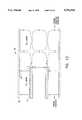
- FIG. 16shows details of the waveguide construction in the waveguide system 82, indicated diagrammatically also in FIG. 3.
- the waveguide system 82provides signal processing functions in the sense of combining and separating transmitted and received signals, as well as providing for a filtering of the signals.
- the waveguide system 82provides the important function of establishing the desired polarizations for signals inputted to the launch waveguides 74 and the feed tube 70.
- FIG. 16shows the waveguides 176, 180, and the feed tube 70 shown previously in FIG. 154.
- the magic Tee's 172 and 174are connected by the plates 80 and 81 to the launcher 72. It is noted also that FIG. 16 has been simplified by deletion of the piston 90.
- the piston 90is an optional part of the feed 56 and plays no significant role in terms of the electromagnetic propagation of signals from the waveguide system 82 to the launcher 72. Accordingly, to facilitate the description, the mounting plate 80 is shown in FIG. 16 as being connected directly to the mounting plate 81 which connects with the launcher 72.
- the transmitters 190 of FIG. 3are shown in greater detail in FIG. 16 as transmitters 190K, 190X and 190C corresponding to the Ku, the X and the C band radiations.
- the receivers 192 of FIG. 3are shown in greater detail in FIG. 16 which shows the receivers 192C, 192X, and 192K.
- the Ku and the X band signalsare coupled from the feed tube 70 via a switch 194 which couples signals of the feed tube 70 alternately to a waveguide 196 or to a waveguide 198.
- the waveguide 196is coupled via an orthomode junction (OMJ) 200 and a filter 202 to the Ku band transmitter 190K.
- OMJorthomode junction
- the waveguide 196is coupled via the OMJ 200 and a filter 204 to the Ku band receiver 192K.
- the waveguide 198is coupled via a septum polarizer 206 and a filter 208 to the X band transmitter 190X.
- the waveguide 198is coupled via the polarizer 206 and a filter 210 and a low noise amplifier (LNA) 212 to the X band receiver 192X.
- LNAlow noise amplifier
- the filter 202is a band reject filter
- the filter 208is a band pass filter
- the filter 210is a band pass filter
- the filter 204is a band reject filter.
- the signals in the waveguides 176 and 180are coupled via diplexers 214 and 216 and hybrid couplers 218 and 220 to the C band transmitter 190C and the C band receiver 192C.
- Each of the hybrid couplers 218 and 220introduces a 90° phase shift between transmitted signals exiting the coupler to respective ones of the diplexers 214 and 216.
- a bandpass filter 222interconnects the hybrid coupler 220 with the transmitter 190C
- a low noise amplifier 224couples the hybrid coupler 218 to the receiver 192C.
- a low-noise amplifier 226connects the filter 204 to the Ku band receiver 192K.
- the signals in the waveguides 196 and 198are separated as to frequency such that the waveguides 196 carries Ku band signals and the waveguide 198 carries X band signals.
- the port of the OMJ 200 connecting with the filter 202is depicted as a broad wall while the port of the OMJ 200 connecting with the filter 204 is portrayed as a narrow wall. This portrayal is intended to indicate the cross-polarization of linear TE waves coupled between the transmitter 190K and the OMJ 200 as compared to signals coupled between the receiver 192K and the OMJ 200.
- the OMJ 200is able to couple signals of differing polarizations to the waveguide 196, thereby to enable signals transmitted and received via the inner feed waveguide of the tube 70 to have differing polarizations.
- the X band transmitted signals and the X band received signalsare split at the polarizer 206 and are separated by the bandpass filters 208 and 210.
- the bandpass filters 208 and 210In the case of the Ku band signals, there is one transmission band and one reception band and, accordingly, it suffices to use the band reject filters 202 and 204 to separate these signals.
- the polarizations of the signals in the waveguides 196 and 198are retained by the switch 194 so as to be transmitted (or received) via the feed tube 70.
- the diplexers 214 and 216include filters (not shown) for separation of the transmit bands from the receive bands of the C band signals.
- the C band transmitteroutputs a TE ode to the hybrid coupler 220.
- the hybrid coupler 220via the diplexers 214 and 216, applies the transmit signal to each of the waveguides 176 and 180 for energization of opposed pairs of the launch waveguides 74. Since the two opposed sets of the launch waveguides 74 are positioned at space quadrature within the launcher 72, the transmitted C band signals may be either linearly polarized or circularly polarized depending on the phasing of the TE waves in the two pairs of the launch waveguides 74.
- the hybrid coupler 220introduces a 90° phase shift between the two signals resulting in a circularly polarized wave emitted by the feed 56.
- the hybrid coupler 220may be replaced with a power splitter (combiner) 228 which enables transmission of the two branches of the signal with the same phase to radiate linearly polarized radiation. Similar comments apply to the reception of signals via the hybrid cover 218 such that the hybrid cover 218 enables reception of circularly polarized signals which are converted to a linear polarized TE signal.
- the linearly polarized signalis applied to the low noise amplifier 224, the amplifier 224 amplifying the signal for further processing at the receiver 192C.
- the hybrid coupler 218is replaced with the power splitter (combiner) 228.
- FIG. 17shows details in the construction of the switch 194.
- a common port 230connects with the feed tube 70 (FIG. 16). Opposite the common port 230 are two switched ports 232 and 234 .
- a block 236is mounted for sliding within a housing 238 of the switch 194, and contains passages 240 and 242 which can be placed between either one of the switched ports 232 and 234 and the common port 230.
- the passages 240 and 242are arranged in a side-by-side format so that one position of the block 236 places one of the switched ports in communication with the common port while, in a second position of the block 236, the other of the switched ports is placed in communication with the common port.
- the radiating aperture of the feed tube 70comprises the aforementioned neck 128 with the outer corrugation in the form of the deep reentrant cavity 130 and including also the dielectric plug 144.
- the rod (or plug) 144is constructed of Teflon.
- a similar dielectric material, or Nylon, by way of further exampleis employed in construction of the sleeve 162, the ring 166, and the screws 168 which secure the window 164 to the front end of the shroud 62.
- the rod 144vy virtue of its dielectric constant is operative to attain, in cooperation with the shroud 126, a desired beneficial radiation directivity pattern.
- this construction of the radiating aperture of the feed tube 70is useful in reducing moding and side lobes even in the absence of the horn 68 and the shroud 62.
- the construction of the inner feed waveguide and its front-end radiating structureis useful as a stand-alone device separate from the rest of the feed 56, and is operative at both the X and the Ku frequency bands.
- the thickness of the outer wall 134is 0.05 inches in the preferred embodiment, it being understood that the dimensions of the neck 128 apply to the preferred embodiment of the invention and may be altered in the case of the transmission of signals at the other frequencies.
- the inner wall 132has a thickness of 0.05 inch.
- the width of the cavity 130, as measured between the walls 132 and 134is 0.06 inch.
- the lengths of the walls 132 and 134are 0.8 inch and 0.45 inch, respectively.
- the length of the neck 128 from the beginning of the transition 136 until the outer end of the inner wall 132is 1.55 inch.
- the inside diameter of the neckis 0.85 inch.
- the inside diameter of the feed tube 70 at the beginning of the transition 136is 1.07 inch.
- the entrance angle of the cavity 146is equal to 32 degrees, and the diameter of the rod 144 is 0.848 inch.
- the overall length of the rod 144, prior to formation of the forward cavity 154, and prior to the tapering of the front edge of the cavity 154,is 2.823 inch. This dimension is reduced upon tapering the front edge to 25° from the horizontal and upon introduction of the forward cavity 154.
- the depth of the chamfer at the cavity floor 156is 0.15 inch.
- the deepest point of the chamfer in the floor 156is located at a depth of 0.65 inch.
- the taper at the front end of the cavity 154has a depth of 0.15 inches, and extends from an outer diameter of 5/8 inch to the diameter of the cavity 154 which is 9/32 inch.
- the lip 142 of the shallow reentrant cavity 126 of the shroud 62has a depth of 0.13 inches, and is set forward of the end of the outer neck wall 134 by 0.9 inch.
- the length of the outer feed waveguide 66is 10.1 inches.
- the length of the star-ridge assembly 106 as measured along the axis 100,is 3 inches.
- the axial length of the launcher 72is 7 inches.
Landscapes
- Physics & Mathematics (AREA)
- Electromagnetism (AREA)
- Waveguide Aerials (AREA)
- Variable-Direction Aerials And Aerial Arrays (AREA)
Abstract
Description
Claims (23)
Priority Applications (4)
| Application Number | Priority Date | Filing Date | Title |
|---|---|---|---|
| US08/698,234US5793334A (en) | 1996-08-14 | 1996-08-14 | Shrouded horn feed assembly |
| PCT/US1997/013992WO1998007211A1 (en) | 1996-08-14 | 1997-08-08 | Shrouded horn feed assembly |
| AU39741/97AAU3974197A (en) | 1996-08-14 | 1997-08-08 | Shrouded horn feed assembly |
| TW086111589ATW347600B (en) | 1996-08-14 | 1997-08-12 | Shrouded horn feed assembly |
Applications Claiming Priority (1)
| Application Number | Priority Date | Filing Date | Title |
|---|---|---|---|
| US08/698,234US5793334A (en) | 1996-08-14 | 1996-08-14 | Shrouded horn feed assembly |
Publications (1)
| Publication Number | Publication Date |
|---|---|
| US5793334Atrue US5793334A (en) | 1998-08-11 |
Family
ID=24804433
Family Applications (1)
| Application Number | Title | Priority Date | Filing Date |
|---|---|---|---|
| US08/698,234Expired - LifetimeUS5793334A (en) | 1996-08-14 | 1996-08-14 | Shrouded horn feed assembly |
Country Status (4)
| Country | Link |
|---|---|
| US (1) | US5793334A (en) |
| AU (1) | AU3974197A (en) |
| TW (1) | TW347600B (en) |
| WO (1) | WO1998007211A1 (en) |
Cited By (210)
| Publication number | Priority date | Publication date | Assignee | Title |
|---|---|---|---|---|
| US6025809A (en)* | 1998-07-31 | 2000-02-15 | Hughes Electronics Corporation | Antenna radiating element |
| US6081170A (en)* | 1997-09-01 | 2000-06-27 | Sharp Kabushiki Kaisha | Dual frequency primary radiator |
| US6323819B1 (en) | 2000-10-05 | 2001-11-27 | Harris Corporation | Dual band multimode coaxial tracking feed |
| US6535174B2 (en)* | 1999-12-20 | 2003-03-18 | Hughes Electronics Corporation | Multi-mode square horn with cavity-suppressed higher-order modes |
| US6603438B2 (en)* | 2001-02-22 | 2003-08-05 | Ems Technologies Canada Ltd. | High power broadband feed |
| US6714165B2 (en)* | 2000-05-23 | 2004-03-30 | Newtec Cy | Ka/Ku dual band feedhorn and orthomode transduce (OMT) |
| US6724277B2 (en)* | 2001-01-24 | 2004-04-20 | Raytheon Company | Radio frequency antenna feed structures having a coaxial waveguide and asymmetric septum |
| US6803875B1 (en) | 2002-09-20 | 2004-10-12 | Drs Weather Systems, Inc. | Simulatneous dual polarization radar system |
| US20050007287A1 (en)* | 2003-06-24 | 2005-01-13 | Bhashyam Balaji | Multiple phase center feedhorn for reflector antenna |
| US6859163B2 (en) | 2002-09-20 | 2005-02-22 | Drs Weather Systems, Inc. | Simultaneous dual polarization radar system |
| US20050093734A1 (en)* | 2002-09-20 | 2005-05-05 | Alford James L. | Simultaneous dual polarization radar system |
| US6909411B1 (en)* | 1999-07-23 | 2005-06-21 | Semiconductor Energy Laboratory Co., Ltd. | Display device and method for operating the same |
| US20050168393A1 (en)* | 2003-09-09 | 2005-08-04 | Apostolos John T. | Collapsible wide band width discone antenna |
| US20060196871A1 (en)* | 2003-05-20 | 2006-09-07 | Risman Per Olof G | Microwave heating device |
| US20060290585A1 (en)* | 2005-06-23 | 2006-12-28 | The Regents Of The University Of California | Antenna with reduced interference |
| US20070222661A1 (en)* | 2006-03-22 | 2007-09-27 | Stagliano James J Jr | Phase shifted transmitted signals in a simultaneous dual polarization weather system |
| US20070222660A1 (en)* | 2006-03-22 | 2007-09-27 | Stagliano James J Jr | Encoded transmitted signals in a simultaneous dual polarization weather system |
| US20070273599A1 (en)* | 2006-05-24 | 2007-11-29 | Adventenna, Inc. | Integrated waveguide antenna and array |
| US20080012656A1 (en)* | 2006-07-12 | 2008-01-17 | Stagliano James J | Method and apparatus for automatic high power tube recovery |
| US20080012757A1 (en)* | 2006-07-12 | 2008-01-17 | Stagliano James J | Method and apparatus implementing a scan strategy for automatic high power tube recovery |
| US20080012756A1 (en)* | 2006-07-12 | 2008-01-17 | Stagliano James J | System and method for measuring phase and power variance |
| US20080036664A1 (en)* | 2006-05-24 | 2008-02-14 | Adventenna Inc. | Variable dielectric constant-based antenna and array |
| US20080048922A1 (en)* | 2006-05-24 | 2008-02-28 | Haziza Dedi D | Integrated waveguide antenna array |
| US20080111755A1 (en)* | 2006-05-24 | 2008-05-15 | Haziza Dedi David | antenna operable at two frequency bands simultaneously |
| US20080117113A1 (en)* | 2006-05-24 | 2008-05-22 | Haziza Dedi David | Integrated waveguide cavity antenna and reflector rf feed |
| US20080117114A1 (en)* | 2006-05-24 | 2008-05-22 | Haziza Dedi David | Apparatus and method for antenna rf feed |
| US20080165052A1 (en)* | 2005-05-23 | 2008-07-10 | Henry Andersson | Simultaneous Dual Polarization Radar System with Pedestal Mounted Receiver |
| US20080303739A1 (en)* | 2007-06-07 | 2008-12-11 | Thomas Edward Sharon | Integrated multi-beam antenna receiving system with improved signal distribution |
| US20080316142A1 (en)* | 2006-05-24 | 2008-12-25 | Wavebender, Inc. | Multiple-input switch design |
| US20090179809A1 (en)* | 2008-01-14 | 2009-07-16 | Cheng-Geng Jan | Dual frequency feed assembly |
| US20090309801A1 (en)* | 2008-06-11 | 2009-12-17 | Lockheed Martin Corporation | Antenna systems for multiple frequency bands |
| US20100149061A1 (en)* | 2008-12-12 | 2010-06-17 | Haziza Dedi David | Integrated waveguide cavity antenna and reflector dish |
| CN102136631A (en)* | 2010-11-01 | 2011-07-27 | 西安空间无线电技术研究所 | S/X double-band circularly polarization feed source |
| US20110291903A1 (en)* | 2010-05-27 | 2011-12-01 | Orbit Communication System Ltd. | Multi band telemetry antenna feed |
| US20140028532A1 (en)* | 2012-07-24 | 2014-01-30 | The Boeing Company | Inflatable antenna |
| US8665036B1 (en) | 2011-06-30 | 2014-03-04 | L-3 Communications | Compact tracking coupler |
| US20150045093A1 (en)* | 2013-08-07 | 2015-02-12 | Skyle D. Hansen, SR. | Shroud assembly for communication site |
| US9154966B2 (en) | 2013-11-06 | 2015-10-06 | At&T Intellectual Property I, Lp | Surface-wave communications and methods thereof |
| US20150288068A1 (en)* | 2012-11-06 | 2015-10-08 | Sharp Kabushiki Kaisha | Primary radiator |
| US20150311596A1 (en)* | 2014-04-24 | 2015-10-29 | Honeywell International Inc. | Dielectric hollow antenna |
| US9209902B2 (en) | 2013-12-10 | 2015-12-08 | At&T Intellectual Property I, L.P. | Quasi-optical coupler |
| US9312919B1 (en) | 2014-10-21 | 2016-04-12 | At&T Intellectual Property I, Lp | Transmission device with impairment compensation and methods for use therewith |
| US9461706B1 (en) | 2015-07-31 | 2016-10-04 | At&T Intellectual Property I, Lp | Method and apparatus for exchanging communication signals |
| US9490869B1 (en) | 2015-05-14 | 2016-11-08 | At&T Intellectual Property I, L.P. | Transmission medium having multiple cores and methods for use therewith |
| US9503189B2 (en) | 2014-10-10 | 2016-11-22 | At&T Intellectual Property I, L.P. | Method and apparatus for arranging communication sessions in a communication system |
| US9509415B1 (en) | 2015-06-25 | 2016-11-29 | At&T Intellectual Property I, L.P. | Methods and apparatus for inducing a fundamental wave mode on a transmission medium |
| US9520945B2 (en) | 2014-10-21 | 2016-12-13 | At&T Intellectual Property I, L.P. | Apparatus for providing communication services and methods thereof |
| US9525524B2 (en) | 2013-05-31 | 2016-12-20 | At&T Intellectual Property I, L.P. | Remote distributed antenna system |
| US9525210B2 (en) | 2014-10-21 | 2016-12-20 | At&T Intellectual Property I, L.P. | Guided-wave transmission device with non-fundamental mode propagation and methods for use therewith |
| US9531427B2 (en) | 2014-11-20 | 2016-12-27 | At&T Intellectual Property I, L.P. | Transmission device with mode division multiplexing and methods for use therewith |
| US9564947B2 (en) | 2014-10-21 | 2017-02-07 | At&T Intellectual Property I, L.P. | Guided-wave transmission device with diversity and methods for use therewith |
| US9577307B2 (en) | 2014-10-21 | 2017-02-21 | At&T Intellectual Property I, L.P. | Guided-wave transmission device and methods for use therewith |
| US9608692B2 (en) | 2015-06-11 | 2017-03-28 | At&T Intellectual Property I, L.P. | Repeater and methods for use therewith |
| US9608740B2 (en) | 2015-07-15 | 2017-03-28 | At&T Intellectual Property I, L.P. | Method and apparatus for launching a wave mode that mitigates interference |
| US9615269B2 (en) | 2014-10-02 | 2017-04-04 | At&T Intellectual Property I, L.P. | Method and apparatus that provides fault tolerance in a communication network |
| US9628854B2 (en) | 2014-09-29 | 2017-04-18 | At&T Intellectual Property I, L.P. | Method and apparatus for distributing content in a communication network |
| US9628116B2 (en) | 2015-07-14 | 2017-04-18 | At&T Intellectual Property I, L.P. | Apparatus and methods for transmitting wireless signals |
| US9640850B2 (en) | 2015-06-25 | 2017-05-02 | At&T Intellectual Property I, L.P. | Methods and apparatus for inducing a non-fundamental wave mode on a transmission medium |
| US9654173B2 (en) | 2014-11-20 | 2017-05-16 | At&T Intellectual Property I, L.P. | Apparatus for powering a communication device and methods thereof |
| US9653770B2 (en) | 2014-10-21 | 2017-05-16 | At&T Intellectual Property I, L.P. | Guided wave coupler, coupling module and methods for use therewith |
| US9667317B2 (en) | 2015-06-15 | 2017-05-30 | At&T Intellectual Property I, L.P. | Method and apparatus for providing security using network traffic adjustments |
| US9680670B2 (en) | 2014-11-20 | 2017-06-13 | At&T Intellectual Property I, L.P. | Transmission device with channel equalization and control and methods for use therewith |
| US9685992B2 (en) | 2014-10-03 | 2017-06-20 | At&T Intellectual Property I, L.P. | Circuit panel network and methods thereof |
| US20170179597A1 (en)* | 2015-12-17 | 2017-06-22 | Viasat, Inc. | Multi-band antenna for communication with multiple co-located satellites |
| US9692101B2 (en) | 2014-08-26 | 2017-06-27 | At&T Intellectual Property I, L.P. | Guided wave couplers for coupling electromagnetic waves between a waveguide surface and a surface of a wire |
| US9699785B2 (en) | 2012-12-05 | 2017-07-04 | At&T Intellectual Property I, L.P. | Backhaul link for distributed antenna system |
| US20170194714A1 (en)* | 2016-01-06 | 2017-07-06 | The SETI Institute | Cooled antenna feed for a telescope array |
| US9705561B2 (en) | 2015-04-24 | 2017-07-11 | At&T Intellectual Property I, L.P. | Directional coupling device and methods for use therewith |
| US9705571B2 (en) | 2015-09-16 | 2017-07-11 | At&T Intellectual Property I, L.P. | Method and apparatus for use with a radio distributed antenna system |
| US9722318B2 (en) | 2015-07-14 | 2017-08-01 | At&T Intellectual Property I, L.P. | Method and apparatus for coupling an antenna to a device |
| US9729197B2 (en) | 2015-10-01 | 2017-08-08 | At&T Intellectual Property I, L.P. | Method and apparatus for communicating network management traffic over a network |
| US9735833B2 (en) | 2015-07-31 | 2017-08-15 | At&T Intellectual Property I, L.P. | Method and apparatus for communications management in a neighborhood network |
| US9742462B2 (en) | 2014-12-04 | 2017-08-22 | At&T Intellectual Property I, L.P. | Transmission medium and communication interfaces and methods for use therewith |
| US9749053B2 (en) | 2015-07-23 | 2017-08-29 | At&T Intellectual Property I, L.P. | Node device, repeater and methods for use therewith |
| US9748626B2 (en) | 2015-05-14 | 2017-08-29 | At&T Intellectual Property I, L.P. | Plurality of cables having different cross-sectional shapes which are bundled together to form a transmission medium |
| US9749013B2 (en) | 2015-03-17 | 2017-08-29 | At&T Intellectual Property I, L.P. | Method and apparatus for reducing attenuation of electromagnetic waves guided by a transmission medium |
| US9755697B2 (en) | 2014-09-15 | 2017-09-05 | At&T Intellectual Property I, L.P. | Method and apparatus for sensing a condition in a transmission medium of electromagnetic waves |
| US9762289B2 (en) | 2014-10-14 | 2017-09-12 | At&T Intellectual Property I, L.P. | Method and apparatus for transmitting or receiving signals in a transportation system |
| US9769020B2 (en) | 2014-10-21 | 2017-09-19 | At&T Intellectual Property I, L.P. | Method and apparatus for responding to events affecting communications in a communication network |
| US9769128B2 (en) | 2015-09-28 | 2017-09-19 | At&T Intellectual Property I, L.P. | Method and apparatus for encryption of communications over a network |
| US9780834B2 (en) | 2014-10-21 | 2017-10-03 | At&T Intellectual Property I, L.P. | Method and apparatus for transmitting electromagnetic waves |
| US9793955B2 (en) | 2015-04-24 | 2017-10-17 | At&T Intellectual Property I, Lp | Passive electrical coupling device and methods for use therewith |
| US9793951B2 (en) | 2015-07-15 | 2017-10-17 | At&T Intellectual Property I, L.P. | Method and apparatus for launching a wave mode that mitigates interference |
| US9793954B2 (en) | 2015-04-28 | 2017-10-17 | At&T Intellectual Property I, L.P. | Magnetic coupling device and methods for use therewith |
| US9800327B2 (en) | 2014-11-20 | 2017-10-24 | At&T Intellectual Property I, L.P. | Apparatus for controlling operations of a communication device and methods thereof |
| US9820146B2 (en) | 2015-06-12 | 2017-11-14 | At&T Intellectual Property I, L.P. | Method and apparatus for authentication and identity management of communicating devices |
| US9836957B2 (en) | 2015-07-14 | 2017-12-05 | At&T Intellectual Property I, L.P. | Method and apparatus for communicating with premises equipment |
| US9838896B1 (en) | 2016-12-09 | 2017-12-05 | At&T Intellectual Property I, L.P. | Method and apparatus for assessing network coverage |
| US9847566B2 (en) | 2015-07-14 | 2017-12-19 | At&T Intellectual Property I, L.P. | Method and apparatus for adjusting a field of a signal to mitigate interference |
| US9847850B2 (en) | 2014-10-14 | 2017-12-19 | At&T Intellectual Property I, L.P. | Method and apparatus for adjusting a mode of communication in a communication network |
| US9853342B2 (en) | 2015-07-14 | 2017-12-26 | At&T Intellectual Property I, L.P. | Dielectric transmission medium connector and methods for use therewith |
| US9860075B1 (en) | 2016-08-26 | 2018-01-02 | At&T Intellectual Property I, L.P. | Method and communication node for broadband distribution |
| US9865911B2 (en) | 2015-06-25 | 2018-01-09 | At&T Intellectual Property I, L.P. | Waveguide system for slot radiating first electromagnetic waves that are combined into a non-fundamental wave mode second electromagnetic wave on a transmission medium |
| US9866309B2 (en) | 2015-06-03 | 2018-01-09 | At&T Intellectual Property I, Lp | Host node device and methods for use therewith |
| US9871283B2 (en) | 2015-07-23 | 2018-01-16 | At&T Intellectual Property I, Lp | Transmission medium having a dielectric core comprised of plural members connected by a ball and socket configuration |
| US9871282B2 (en) | 2015-05-14 | 2018-01-16 | At&T Intellectual Property I, L.P. | At least one transmission medium having a dielectric surface that is covered at least in part by a second dielectric |
| US9876605B1 (en) | 2016-10-21 | 2018-01-23 | At&T Intellectual Property I, L.P. | Launcher and coupling system to support desired guided wave mode |
| US9876570B2 (en) | 2015-02-20 | 2018-01-23 | At&T Intellectual Property I, Lp | Guided-wave transmission device with non-fundamental mode propagation and methods for use therewith |
| US9876264B2 (en) | 2015-10-02 | 2018-01-23 | At&T Intellectual Property I, Lp | Communication system, guided wave switch and methods for use therewith |
| US9882277B2 (en) | 2015-10-02 | 2018-01-30 | At&T Intellectual Property I, Lp | Communication device and antenna assembly with actuated gimbal mount |
| US9882257B2 (en) | 2015-07-14 | 2018-01-30 | At&T Intellectual Property I, L.P. | Method and apparatus for launching a wave mode that mitigates interference |
| US9893795B1 (en) | 2016-12-07 | 2018-02-13 | At&T Intellectual Property I, Lp | Method and repeater for broadband distribution |
| US9904535B2 (en) | 2015-09-14 | 2018-02-27 | At&T Intellectual Property I, L.P. | Method and apparatus for distributing software |
| US9906269B2 (en) | 2014-09-17 | 2018-02-27 | At&T Intellectual Property I, L.P. | Monitoring and mitigating conditions in a communication network |
| US9911020B1 (en) | 2016-12-08 | 2018-03-06 | At&T Intellectual Property I, L.P. | Method and apparatus for tracking via a radio frequency identification device |
| US9913139B2 (en) | 2015-06-09 | 2018-03-06 | At&T Intellectual Property I, L.P. | Signal fingerprinting for authentication of communicating devices |
| US9912419B1 (en) | 2016-08-24 | 2018-03-06 | At&T Intellectual Property I, L.P. | Method and apparatus for managing a fault in a distributed antenna system |
| US9912382B2 (en) | 2015-06-03 | 2018-03-06 | At&T Intellectual Property I, Lp | Network termination and methods for use therewith |
| US9912027B2 (en) | 2015-07-23 | 2018-03-06 | At&T Intellectual Property I, L.P. | Method and apparatus for exchanging communication signals |
| US9917341B2 (en) | 2015-05-27 | 2018-03-13 | At&T Intellectual Property I, L.P. | Apparatus and method for launching electromagnetic waves and for modifying radial dimensions of the propagating electromagnetic waves |
| US9927517B1 (en) | 2016-12-06 | 2018-03-27 | At&T Intellectual Property I, L.P. | Apparatus and methods for sensing rainfall |
| US9948333B2 (en) | 2015-07-23 | 2018-04-17 | At&T Intellectual Property I, L.P. | Method and apparatus for wireless communications to mitigate interference |
| US9948354B2 (en) | 2015-04-28 | 2018-04-17 | At&T Intellectual Property I, L.P. | Magnetic coupling device with reflective plate and methods for use therewith |
| US9954287B2 (en) | 2014-11-20 | 2018-04-24 | At&T Intellectual Property I, L.P. | Apparatus for converting wireless signals and electromagnetic waves and methods thereof |
| US9967173B2 (en) | 2015-07-31 | 2018-05-08 | At&T Intellectual Property I, L.P. | Method and apparatus for authentication and identity management of communicating devices |
| US9973940B1 (en) | 2017-02-27 | 2018-05-15 | At&T Intellectual Property I, L.P. | Apparatus and methods for dynamic impedance matching of a guided wave launcher |
| US9991580B2 (en) | 2016-10-21 | 2018-06-05 | At&T Intellectual Property I, L.P. | Launcher and coupling system for guided wave mode cancellation |
| US9999038B2 (en) | 2013-05-31 | 2018-06-12 | At&T Intellectual Property I, L.P. | Remote distributed antenna system |
| US9998870B1 (en) | 2016-12-08 | 2018-06-12 | At&T Intellectual Property I, L.P. | Method and apparatus for proximity sensing |
| US9997819B2 (en) | 2015-06-09 | 2018-06-12 | At&T Intellectual Property I, L.P. | Transmission medium and method for facilitating propagation of electromagnetic waves via a core |
| US10009063B2 (en) | 2015-09-16 | 2018-06-26 | At&T Intellectual Property I, L.P. | Method and apparatus for use with a radio distributed antenna system having an out-of-band reference signal |
| US10009065B2 (en) | 2012-12-05 | 2018-06-26 | At&T Intellectual Property I, L.P. | Backhaul link for distributed antenna system |
| US10009901B2 (en) | 2015-09-16 | 2018-06-26 | At&T Intellectual Property I, L.P. | Method, apparatus, and computer-readable storage medium for managing utilization of wireless resources between base stations |
| US10009067B2 (en) | 2014-12-04 | 2018-06-26 | At&T Intellectual Property I, L.P. | Method and apparatus for configuring a communication interface |
| US10020587B2 (en) | 2015-07-31 | 2018-07-10 | At&T Intellectual Property I, L.P. | Radial antenna and methods for use therewith |
| US10020844B2 (en) | 2016-12-06 | 2018-07-10 | T&T Intellectual Property I, L.P. | Method and apparatus for broadcast communication via guided waves |
| US10027397B2 (en) | 2016-12-07 | 2018-07-17 | At&T Intellectual Property I, L.P. | Distributed antenna system and methods for use therewith |
| US10033108B2 (en) | 2015-07-14 | 2018-07-24 | At&T Intellectual Property I, L.P. | Apparatus and methods for generating an electromagnetic wave having a wave mode that mitigates interference |
| US10033107B2 (en) | 2015-07-14 | 2018-07-24 | At&T Intellectual Property I, L.P. | Method and apparatus for coupling an antenna to a device |
| US10044409B2 (en) | 2015-07-14 | 2018-08-07 | At&T Intellectual Property I, L.P. | Transmission medium and methods for use therewith |
| US10051629B2 (en) | 2015-09-16 | 2018-08-14 | At&T Intellectual Property I, L.P. | Method and apparatus for use with a radio distributed antenna system having an in-band reference signal |
| US10051483B2 (en) | 2015-10-16 | 2018-08-14 | At&T Intellectual Property I, L.P. | Method and apparatus for directing wireless signals |
| US10069535B2 (en) | 2016-12-08 | 2018-09-04 | At&T Intellectual Property I, L.P. | Apparatus and methods for launching electromagnetic waves having a certain electric field structure |
| US10074890B2 (en) | 2015-10-02 | 2018-09-11 | At&T Intellectual Property I, L.P. | Communication device and antenna with integrated light assembly |
| US10079661B2 (en) | 2015-09-16 | 2018-09-18 | At&T Intellectual Property I, L.P. | Method and apparatus for use with a radio distributed antenna system having a clock reference |
| US10090594B2 (en) | 2016-11-23 | 2018-10-02 | At&T Intellectual Property I, L.P. | Antenna system having structural configurations for assembly |
| US10090606B2 (en) | 2015-07-15 | 2018-10-02 | At&T Intellectual Property I, L.P. | Antenna system with dielectric array and methods for use therewith |
| US10103801B2 (en) | 2015-06-03 | 2018-10-16 | At&T Intellectual Property I, L.P. | Host node device and methods for use therewith |
| US10103422B2 (en) | 2016-12-08 | 2018-10-16 | At&T Intellectual Property I, L.P. | Method and apparatus for mounting network devices |
| CN108701900A (en)* | 2017-01-22 | 2018-10-23 | 华为技术有限公司 | A dual frequency antenna |
| US10135146B2 (en) | 2016-10-18 | 2018-11-20 | At&T Intellectual Property I, L.P. | Apparatus and methods for launching guided waves via circuits |
| US10136434B2 (en) | 2015-09-16 | 2018-11-20 | At&T Intellectual Property I, L.P. | Method and apparatus for use with a radio distributed antenna system having an ultra-wideband control channel |
| US10135145B2 (en) | 2016-12-06 | 2018-11-20 | At&T Intellectual Property I, L.P. | Apparatus and methods for generating an electromagnetic wave along a transmission medium |
| US10135147B2 (en) | 2016-10-18 | 2018-11-20 | At&T Intellectual Property I, L.P. | Apparatus and methods for launching guided waves via an antenna |
| US10139820B2 (en) | 2016-12-07 | 2018-11-27 | At&T Intellectual Property I, L.P. | Method and apparatus for deploying equipment of a communication system |
| US10142086B2 (en) | 2015-06-11 | 2018-11-27 | At&T Intellectual Property I, L.P. | Repeater and methods for use therewith |
| US10144036B2 (en) | 2015-01-30 | 2018-12-04 | At&T Intellectual Property I, L.P. | Method and apparatus for mitigating interference affecting a propagation of electromagnetic waves guided by a transmission medium |
| US10148016B2 (en) | 2015-07-14 | 2018-12-04 | At&T Intellectual Property I, L.P. | Apparatus and methods for communicating utilizing an antenna array |
| US10154493B2 (en) | 2015-06-03 | 2018-12-11 | At&T Intellectual Property I, L.P. | Network termination and methods for use therewith |
| US10170840B2 (en) | 2015-07-14 | 2019-01-01 | At&T Intellectual Property I, L.P. | Apparatus and methods for sending or receiving electromagnetic signals |
| US10168695B2 (en) | 2016-12-07 | 2019-01-01 | At&T Intellectual Property I, L.P. | Method and apparatus for controlling an unmanned aircraft |
| US10178445B2 (en) | 2016-11-23 | 2019-01-08 | At&T Intellectual Property I, L.P. | Methods, devices, and systems for load balancing between a plurality of waveguides |
| US10205655B2 (en) | 2015-07-14 | 2019-02-12 | At&T Intellectual Property I, L.P. | Apparatus and methods for communicating utilizing an antenna array and multiple communication paths |
| US10225025B2 (en) | 2016-11-03 | 2019-03-05 | At&T Intellectual Property I, L.P. | Method and apparatus for detecting a fault in a communication system |
| US10224634B2 (en) | 2016-11-03 | 2019-03-05 | At&T Intellectual Property I, L.P. | Methods and apparatus for adjusting an operational characteristic of an antenna |
| CN109473775A (en)* | 2019-01-07 | 2019-03-15 | 北京西宝电子技术有限责任公司 | Ku/E band dual frequency integrated feed |
| US10243784B2 (en) | 2014-11-20 | 2019-03-26 | At&T Intellectual Property I, L.P. | System for generating topology information and methods thereof |
| US10243270B2 (en) | 2016-12-07 | 2019-03-26 | At&T Intellectual Property I, L.P. | Beam adaptive multi-feed dielectric antenna system and methods for use therewith |
| US10264586B2 (en) | 2016-12-09 | 2019-04-16 | At&T Mobility Ii Llc | Cloud-based packet controller and methods for use therewith |
| US10291311B2 (en) | 2016-09-09 | 2019-05-14 | At&T Intellectual Property I, L.P. | Method and apparatus for mitigating a fault in a distributed antenna system |
| US10291334B2 (en) | 2016-11-03 | 2019-05-14 | At&T Intellectual Property I, L.P. | System for detecting a fault in a communication system |
| US10298293B2 (en) | 2017-03-13 | 2019-05-21 | At&T Intellectual Property I, L.P. | Apparatus of communication utilizing wireless network devices |
| US10305190B2 (en) | 2016-12-01 | 2019-05-28 | At&T Intellectual Property I, L.P. | Reflecting dielectric antenna system and methods for use therewith |
| US10312567B2 (en) | 2016-10-26 | 2019-06-04 | At&T Intellectual Property I, L.P. | Launcher with planar strip antenna and methods for use therewith |
| US10320586B2 (en) | 2015-07-14 | 2019-06-11 | At&T Intellectual Property I, L.P. | Apparatus and methods for generating non-interfering electromagnetic waves on an insulated transmission medium |
| US10326689B2 (en) | 2016-12-08 | 2019-06-18 | At&T Intellectual Property I, L.P. | Method and system for providing alternative communication paths |
| US10326494B2 (en) | 2016-12-06 | 2019-06-18 | At&T Intellectual Property I, L.P. | Apparatus for measurement de-embedding and methods for use therewith |
| US10340983B2 (en) | 2016-12-09 | 2019-07-02 | At&T Intellectual Property I, L.P. | Method and apparatus for surveying remote sites via guided wave communications |
| US10340573B2 (en) | 2016-10-26 | 2019-07-02 | At&T Intellectual Property I, L.P. | Launcher with cylindrical coupling device and methods for use therewith |
| US10340601B2 (en) | 2016-11-23 | 2019-07-02 | At&T Intellectual Property I, L.P. | Multi-antenna system and methods for use therewith |
| US10340603B2 (en) | 2016-11-23 | 2019-07-02 | At&T Intellectual Property I, L.P. | Antenna system having shielded structural configurations for assembly |
| US10341142B2 (en) | 2015-07-14 | 2019-07-02 | At&T Intellectual Property I, L.P. | Apparatus and methods for generating non-interfering electromagnetic waves on an uninsulated conductor |
| US10340600B2 (en) | 2016-10-18 | 2019-07-02 | At&T Intellectual Property I, L.P. | Apparatus and methods for launching guided waves via plural waveguide systems |
| US10348391B2 (en) | 2015-06-03 | 2019-07-09 | At&T Intellectual Property I, L.P. | Client node device with frequency conversion and methods for use therewith |
| US10355367B2 (en) | 2015-10-16 | 2019-07-16 | At&T Intellectual Property I, L.P. | Antenna structure for exchanging wireless signals |
| US10359749B2 (en) | 2016-12-07 | 2019-07-23 | At&T Intellectual Property I, L.P. | Method and apparatus for utilities management via guided wave communication |
| US10361489B2 (en) | 2016-12-01 | 2019-07-23 | At&T Intellectual Property I, L.P. | Dielectric dish antenna system and methods for use therewith |
| US10374316B2 (en) | 2016-10-21 | 2019-08-06 | At&T Intellectual Property I, L.P. | System and dielectric antenna with non-uniform dielectric |
| US10382976B2 (en) | 2016-12-06 | 2019-08-13 | At&T Intellectual Property I, L.P. | Method and apparatus for managing wireless communications based on communication paths and network device positions |
| US10389037B2 (en) | 2016-12-08 | 2019-08-20 | At&T Intellectual Property I, L.P. | Apparatus and methods for selecting sections of an antenna array and use therewith |
| US10389029B2 (en) | 2016-12-07 | 2019-08-20 | At&T Intellectual Property I, L.P. | Multi-feed dielectric antenna system with core selection and methods for use therewith |
| US10396887B2 (en) | 2015-06-03 | 2019-08-27 | At&T Intellectual Property I, L.P. | Client node device and methods for use therewith |
| US10411356B2 (en) | 2016-12-08 | 2019-09-10 | At&T Intellectual Property I, L.P. | Apparatus and methods for selectively targeting communication devices with an antenna array |
| US10439675B2 (en) | 2016-12-06 | 2019-10-08 | At&T Intellectual Property I, L.P. | Method and apparatus for repeating guided wave communication signals |
| US10446936B2 (en) | 2016-12-07 | 2019-10-15 | At&T Intellectual Property I, L.P. | Multi-feed dielectric antenna system and methods for use therewith |
| US10498044B2 (en) | 2016-11-03 | 2019-12-03 | At&T Intellectual Property I, L.P. | Apparatus for configuring a surface of an antenna |
| SE541878C2 (en)* | 2018-04-23 | 2020-01-02 | Requtech Ab | Multi-band antenna feed arrangement |
| US10530505B2 (en) | 2016-12-08 | 2020-01-07 | At&T Intellectual Property I, L.P. | Apparatus and methods for launching electromagnetic waves along a transmission medium |
| US10535928B2 (en) | 2016-11-23 | 2020-01-14 | At&T Intellectual Property I, L.P. | Antenna system and methods for use therewith |
| US10547348B2 (en) | 2016-12-07 | 2020-01-28 | At&T Intellectual Property I, L.P. | Method and apparatus for switching transmission mediums in a communication system |
| US10601494B2 (en) | 2016-12-08 | 2020-03-24 | At&T Intellectual Property I, L.P. | Dual-band communication device and method for use therewith |
| US10637151B2 (en)* | 2017-04-26 | 2020-04-28 | Electronics And Telecommunications Research Institute | Transceiver in wireless communication system |
| US10637149B2 (en) | 2016-12-06 | 2020-04-28 | At&T Intellectual Property I, L.P. | Injection molded dielectric antenna and methods for use therewith |
| US10650940B2 (en) | 2015-05-15 | 2020-05-12 | At&T Intellectual Property I, L.P. | Transmission medium having a conductive material and methods for use therewith |
| US10665942B2 (en) | 2015-10-16 | 2020-05-26 | At&T Intellectual Property I, L.P. | Method and apparatus for adjusting wireless communications |
| US10679767B2 (en) | 2015-05-15 | 2020-06-09 | At&T Intellectual Property I, L.P. | Transmission medium having a conductive material and methods for use therewith |
| US10694379B2 (en) | 2016-12-06 | 2020-06-23 | At&T Intellectual Property I, L.P. | Waveguide system with device-based authentication and methods for use therewith |
| US10727599B2 (en) | 2016-12-06 | 2020-07-28 | At&T Intellectual Property I, L.P. | Launcher with slot antenna and methods for use therewith |
| US10755542B2 (en) | 2016-12-06 | 2020-08-25 | At&T Intellectual Property I, L.P. | Method and apparatus for surveillance via guided wave communication |
| US10777873B2 (en) | 2016-12-08 | 2020-09-15 | At&T Intellectual Property I, L.P. | Method and apparatus for mounting network devices |
| US10784670B2 (en) | 2015-07-23 | 2020-09-22 | At&T Intellectual Property I, L.P. | Antenna support for aligning an antenna |
| WO2020190264A1 (en)* | 2019-03-15 | 2020-09-24 | Massachusetts Institute Of Technology | Inflatable reflector antenna and related methods |
| US10811767B2 (en) | 2016-10-21 | 2020-10-20 | At&T Intellectual Property I, L.P. | System and dielectric antenna with convex dielectric radome |
| US10819035B2 (en) | 2016-12-06 | 2020-10-27 | At&T Intellectual Property I, L.P. | Launcher with helical antenna and methods for use therewith |
| US10916859B2 (en) | 2019-03-15 | 2021-02-09 | Massachusetts Institute Of Technology | Inflatable reflector antenna and related methods |
| US10916969B2 (en) | 2016-12-08 | 2021-02-09 | At&T Intellectual Property I, L.P. | Method and apparatus for providing power using an inductive coupling |
| US10938108B2 (en) | 2016-12-08 | 2021-03-02 | At&T Intellectual Property I, L.P. | Frequency selective multi-feed dielectric antenna system and methods for use therewith |
| US11032819B2 (en) | 2016-09-15 | 2021-06-08 | At&T Intellectual Property I, L.P. | Method and apparatus for use with a radio distributed antenna system having a control channel reference signal |
| US11424538B2 (en)* | 2018-10-11 | 2022-08-23 | Commscope Technologies Llc | Feed systems for multi-band parabolic reflector microwave antenna systems |
| US11888230B1 (en)* | 2021-05-27 | 2024-01-30 | Space Exploration Technologies Corp. | Antenna assembly including feed system having a sub-reflector |
Families Citing this family (2)
| Publication number | Priority date | Publication date | Assignee | Title |
|---|---|---|---|---|
| GB201511436D0 (en)* | 2015-06-30 | 2015-08-12 | Global Invacom Ltd | Improvements to receiving and/or transmitting apparatus for satellite transmitted data |
| CN115101937B (en)* | 2022-06-20 | 2023-11-03 | 北京航空航天大学 | Horn feed source |
Citations (14)
| Publication number | Priority date | Publication date | Assignee | Title |
|---|---|---|---|---|
| DE963705C (en)* | 1955-03-23 | 1957-05-09 | Siemens Ag | Coupling system with a coupling funnel for surface waveguides |
| US3216017A (en)* | 1962-12-04 | 1965-11-02 | Martin Marietta Corp | Polarizer for use in antenna and transmission line systems |
| US3268902A (en)* | 1963-12-05 | 1966-08-23 | Bell Telephone Labor Inc | Dual frequency microwave aperturetype antenna providing similar radiation pattern on both frequencies |
| US3605101A (en)* | 1969-09-30 | 1971-09-14 | Bell Telephone Labor Inc | Dual mode conical horn antenna |
| GB1269950A (en)* | 1968-11-15 | 1972-04-06 | Plessey Co Ltd | Improvements in or relating to antenna feed systems |
| US4994818A (en)* | 1988-11-03 | 1991-02-19 | Max Planck-Gesellschaft Zur Foerderung Der Wissenschaften E.V. | Scanning tip for optical radiation |
| US5005023A (en)* | 1988-12-01 | 1991-04-02 | Gardiner Communications Corporation | Dual band integrated LNB feedhorn system |
| US5017937A (en)* | 1986-03-25 | 1991-05-21 | The Marconi Company Limited | Wideband horn antenna |
| US5109232A (en)* | 1990-02-20 | 1992-04-28 | Andrew Corporation | Dual frequency antenna feed with apertured channel |
| US5122810A (en)* | 1988-08-24 | 1992-06-16 | Racal-Mesl Limited | Feed waveguide with ferrite rod polarizer and stepped dielectric support for matching |
| US5248987A (en)* | 1991-12-31 | 1993-09-28 | Massachusetts Institute Of Technology | Widebeam antenna |
| US5550553A (en)* | 1993-02-18 | 1996-08-27 | Murata Manufacturing Co., Ltd. | Dielectric rod antenna |
| US5583469A (en)* | 1994-12-15 | 1996-12-10 | Unisys Corporation | Dual frequency waveguide switch |
| US5635944A (en)* | 1994-12-15 | 1997-06-03 | Unisys Corporation | Multi-band antenna feed with switchably shared I/O port |
- 1996
- 1996-08-14USUS08/698,234patent/US5793334A/ennot_activeExpired - Lifetime
- 1997
- 1997-08-08WOPCT/US1997/013992patent/WO1998007211A1/enactiveApplication Filing
- 1997-08-08AUAU39741/97Apatent/AU3974197A/ennot_activeAbandoned
- 1997-08-12TWTW086111589Apatent/TW347600B/enactive
Patent Citations (14)
| Publication number | Priority date | Publication date | Assignee | Title |
|---|---|---|---|---|
| DE963705C (en)* | 1955-03-23 | 1957-05-09 | Siemens Ag | Coupling system with a coupling funnel for surface waveguides |
| US3216017A (en)* | 1962-12-04 | 1965-11-02 | Martin Marietta Corp | Polarizer for use in antenna and transmission line systems |
| US3268902A (en)* | 1963-12-05 | 1966-08-23 | Bell Telephone Labor Inc | Dual frequency microwave aperturetype antenna providing similar radiation pattern on both frequencies |
| GB1269950A (en)* | 1968-11-15 | 1972-04-06 | Plessey Co Ltd | Improvements in or relating to antenna feed systems |
| US3605101A (en)* | 1969-09-30 | 1971-09-14 | Bell Telephone Labor Inc | Dual mode conical horn antenna |
| US5017937A (en)* | 1986-03-25 | 1991-05-21 | The Marconi Company Limited | Wideband horn antenna |
| US5122810A (en)* | 1988-08-24 | 1992-06-16 | Racal-Mesl Limited | Feed waveguide with ferrite rod polarizer and stepped dielectric support for matching |
| US4994818A (en)* | 1988-11-03 | 1991-02-19 | Max Planck-Gesellschaft Zur Foerderung Der Wissenschaften E.V. | Scanning tip for optical radiation |
| US5005023A (en)* | 1988-12-01 | 1991-04-02 | Gardiner Communications Corporation | Dual band integrated LNB feedhorn system |
| US5109232A (en)* | 1990-02-20 | 1992-04-28 | Andrew Corporation | Dual frequency antenna feed with apertured channel |
| US5248987A (en)* | 1991-12-31 | 1993-09-28 | Massachusetts Institute Of Technology | Widebeam antenna |
| US5550553A (en)* | 1993-02-18 | 1996-08-27 | Murata Manufacturing Co., Ltd. | Dielectric rod antenna |
| US5583469A (en)* | 1994-12-15 | 1996-12-10 | Unisys Corporation | Dual frequency waveguide switch |
| US5635944A (en)* | 1994-12-15 | 1997-06-03 | Unisys Corporation | Multi-band antenna feed with switchably shared I/O port |
Cited By (307)
| Publication number | Priority date | Publication date | Assignee | Title |
|---|---|---|---|---|
| US6081170A (en)* | 1997-09-01 | 2000-06-27 | Sharp Kabushiki Kaisha | Dual frequency primary radiator |
| US6025809A (en)* | 1998-07-31 | 2000-02-15 | Hughes Electronics Corporation | Antenna radiating element |
| US6909411B1 (en)* | 1999-07-23 | 2005-06-21 | Semiconductor Energy Laboratory Co., Ltd. | Display device and method for operating the same |
| US20050206598A1 (en)* | 1999-07-23 | 2005-09-22 | Semiconductor Energy Laboratory Co., Ltd. | Display device and method for operating the same |
| US6535174B2 (en)* | 1999-12-20 | 2003-03-18 | Hughes Electronics Corporation | Multi-mode square horn with cavity-suppressed higher-order modes |
| US6714165B2 (en)* | 2000-05-23 | 2004-03-30 | Newtec Cy | Ka/Ku dual band feedhorn and orthomode transduce (OMT) |
| US6323819B1 (en) | 2000-10-05 | 2001-11-27 | Harris Corporation | Dual band multimode coaxial tracking feed |
| US6724277B2 (en)* | 2001-01-24 | 2004-04-20 | Raytheon Company | Radio frequency antenna feed structures having a coaxial waveguide and asymmetric septum |
| US6603438B2 (en)* | 2001-02-22 | 2003-08-05 | Ems Technologies Canada Ltd. | High power broadband feed |
| US20050093734A1 (en)* | 2002-09-20 | 2005-05-05 | Alford James L. | Simultaneous dual polarization radar system |
| US6859163B2 (en) | 2002-09-20 | 2005-02-22 | Drs Weather Systems, Inc. | Simultaneous dual polarization radar system |
| US6803875B1 (en) | 2002-09-20 | 2004-10-12 | Drs Weather Systems, Inc. | Simulatneous dual polarization radar system |
| US7049997B2 (en) | 2002-09-20 | 2006-05-23 | Enterprise Electronics Corporation | Simultaneous dual polarization radar system |
| US20060196871A1 (en)* | 2003-05-20 | 2006-09-07 | Risman Per Olof G | Microwave heating device |
| US7528353B2 (en)* | 2003-05-20 | 2009-05-05 | Biotage Ab | Microwave heating device |
| US20050007287A1 (en)* | 2003-06-24 | 2005-01-13 | Bhashyam Balaji | Multiple phase center feedhorn for reflector antenna |
| US7180459B2 (en)* | 2003-06-24 | 2007-02-20 | Her Majesty the Queen in right of Canada, as represented by the Minister of National Defence of Her Majesty' Canadian Government | Multiple phase center feedhorn for reflector antenna |
| US7167137B2 (en)* | 2003-09-09 | 2007-01-23 | Bae Systems Information And Electronic Systems Integration Inc. | Collapsible wide band width discone antenna |
| US20050168393A1 (en)* | 2003-09-09 | 2005-08-04 | Apostolos John T. | Collapsible wide band width discone antenna |
| US20080165052A1 (en)* | 2005-05-23 | 2008-07-10 | Henry Andersson | Simultaneous Dual Polarization Radar System with Pedestal Mounted Receiver |
| US7495599B2 (en)* | 2005-05-23 | 2009-02-24 | Vaisala Oyj | Simultaneous dual polarization radar system with pedestal mounted receiver |
| US20060290585A1 (en)* | 2005-06-23 | 2006-12-28 | The Regents Of The University Of California | Antenna with reduced interference |
| US7471255B2 (en)* | 2005-06-23 | 2008-12-30 | The Regents Of The University Of California | Antenna with reduced interference |
| US20070222661A1 (en)* | 2006-03-22 | 2007-09-27 | Stagliano James J Jr | Phase shifted transmitted signals in a simultaneous dual polarization weather system |
| US7439899B2 (en) | 2006-03-22 | 2008-10-21 | Enterprise Electronics Corporation | Encoded transmitted signals in a simultaneous dual polarization weather system |
| US7551123B2 (en) | 2006-03-22 | 2009-06-23 | Enterprise Electronics Corporation | Phase shifted transmitted signals in a simultaneous dual polarization weather system |
| US20070222660A1 (en)* | 2006-03-22 | 2007-09-27 | Stagliano James J Jr | Encoded transmitted signals in a simultaneous dual polarization weather system |
| US7656358B2 (en) | 2006-05-24 | 2010-02-02 | Wavebender, Inc. | Antenna operable at two frequency bands simultaneously |
| US7466281B2 (en) | 2006-05-24 | 2008-12-16 | Wavebender, Inc. | Integrated waveguide antenna and array |
| US20080117113A1 (en)* | 2006-05-24 | 2008-05-22 | Haziza Dedi David | Integrated waveguide cavity antenna and reflector rf feed |
| US20080117114A1 (en)* | 2006-05-24 | 2008-05-22 | Haziza Dedi David | Apparatus and method for antenna rf feed |
| US7884779B2 (en) | 2006-05-24 | 2011-02-08 | Wavebender, Inc. | Multiple-input switch design |
| US7656359B2 (en) | 2006-05-24 | 2010-02-02 | Wavebender, Inc. | Apparatus and method for antenna RF feed |
| US7847749B2 (en) | 2006-05-24 | 2010-12-07 | Wavebender, Inc. | Integrated waveguide cavity antenna and reflector RF feed |
| US7961153B2 (en) | 2006-05-24 | 2011-06-14 | Wavebender, Inc. | Integrated waveguide antenna and array |
| US7466269B2 (en) | 2006-05-24 | 2008-12-16 | Wavebender, Inc. | Variable dielectric constant-based antenna and array |
| US20080111755A1 (en)* | 2006-05-24 | 2008-05-15 | Haziza Dedi David | antenna operable at two frequency bands simultaneously |
| US20080316142A1 (en)* | 2006-05-24 | 2008-12-25 | Wavebender, Inc. | Multiple-input switch design |
| US7884766B2 (en) | 2006-05-24 | 2011-02-08 | Wavebender, Inc. | Variable dielectric constant-based antenna and array |
| US20070273599A1 (en)* | 2006-05-24 | 2007-11-29 | Adventenna, Inc. | Integrated waveguide antenna and array |
| US20090058747A1 (en)* | 2006-05-24 | 2009-03-05 | Wavebender, Inc. | Integrated waveguide antenna and array |
| US20090091500A1 (en)* | 2006-05-24 | 2009-04-09 | Wavebender, Inc. | Variable Dielectric Constant-Based Antenna And Array |
| US20080048922A1 (en)* | 2006-05-24 | 2008-02-28 | Haziza Dedi D | Integrated waveguide antenna array |
| US20080036664A1 (en)* | 2006-05-24 | 2008-02-14 | Adventenna Inc. | Variable dielectric constant-based antenna and array |
| US7554505B2 (en) | 2006-05-24 | 2009-06-30 | Wavebender, Inc. | Integrated waveguide antenna array |
| US20080012757A1 (en)* | 2006-07-12 | 2008-01-17 | Stagliano James J | Method and apparatus implementing a scan strategy for automatic high power tube recovery |
| US20080012656A1 (en)* | 2006-07-12 | 2008-01-17 | Stagliano James J | Method and apparatus for automatic high power tube recovery |
| US20080012756A1 (en)* | 2006-07-12 | 2008-01-17 | Stagliano James J | System and method for measuring phase and power variance |
| US7683828B2 (en) | 2006-07-12 | 2010-03-23 | Enterprise Electronics Corporation | System and method for measuring phase and power variance |
| US7750573B2 (en) | 2006-07-12 | 2010-07-06 | Enterprise Electronics Corporation | Method and apparatus for automatic high power tube recovery |
| US7369082B2 (en) | 2006-07-12 | 2008-05-06 | Enterprise Electronics Corporation | Method and apparatus implementing a scan strategy for automatic high power tube recovery |
| WO2008063552A3 (en)* | 2006-11-17 | 2008-07-17 | Wavebender Inc | Integrated waveguide antenna array |
| US20080303739A1 (en)* | 2007-06-07 | 2008-12-11 | Thomas Edward Sharon | Integrated multi-beam antenna receiving system with improved signal distribution |
| US7659861B2 (en)* | 2008-01-14 | 2010-02-09 | Wistron Neweb Corp. | Dual frequency feed assembly |
| CN101488599B (en)* | 2008-01-14 | 2012-10-03 | 启碁科技股份有限公司 | Dual frequency feed assembly |
| US20090179809A1 (en)* | 2008-01-14 | 2009-07-16 | Cheng-Geng Jan | Dual frequency feed assembly |
| US20090309801A1 (en)* | 2008-06-11 | 2009-12-17 | Lockheed Martin Corporation | Antenna systems for multiple frequency bands |
| US7737904B2 (en)* | 2008-06-11 | 2010-06-15 | Lockheed Martin Corporation | Antenna systems for multiple frequency bands |
| US8743004B2 (en) | 2008-12-12 | 2014-06-03 | Dedi David HAZIZA | Integrated waveguide cavity antenna and reflector dish |
| US20100149061A1 (en)* | 2008-12-12 | 2010-06-17 | Haziza Dedi David | Integrated waveguide cavity antenna and reflector dish |
| US20110291903A1 (en)* | 2010-05-27 | 2011-12-01 | Orbit Communication System Ltd. | Multi band telemetry antenna feed |
| US8593362B2 (en)* | 2010-05-27 | 2013-11-26 | Orbit Communication System Ltd. | Multi band telemetry antenna feed |
| CN102136631A (en)* | 2010-11-01 | 2011-07-27 | 西安空间无线电技术研究所 | S/X double-band circularly polarization feed source |
| US8665036B1 (en) | 2011-06-30 | 2014-03-04 | L-3 Communications | Compact tracking coupler |
| US20140028532A1 (en)* | 2012-07-24 | 2014-01-30 | The Boeing Company | Inflatable antenna |
| US9391373B2 (en)* | 2012-07-24 | 2016-07-12 | The Boeing Company | Inflatable antenna |
| US20150288068A1 (en)* | 2012-11-06 | 2015-10-08 | Sharp Kabushiki Kaisha | Primary radiator |
| US10009065B2 (en) | 2012-12-05 | 2018-06-26 | At&T Intellectual Property I, L.P. | Backhaul link for distributed antenna system |
| US9788326B2 (en) | 2012-12-05 | 2017-10-10 | At&T Intellectual Property I, L.P. | Backhaul link for distributed antenna system |
| US9699785B2 (en) | 2012-12-05 | 2017-07-04 | At&T Intellectual Property I, L.P. | Backhaul link for distributed antenna system |
| US10194437B2 (en) | 2012-12-05 | 2019-01-29 | At&T Intellectual Property I, L.P. | Backhaul link for distributed antenna system |
| US9999038B2 (en) | 2013-05-31 | 2018-06-12 | At&T Intellectual Property I, L.P. | Remote distributed antenna system |
| US9930668B2 (en) | 2013-05-31 | 2018-03-27 | At&T Intellectual Property I, L.P. | Remote distributed antenna system |
| US10051630B2 (en) | 2013-05-31 | 2018-08-14 | At&T Intellectual Property I, L.P. | Remote distributed antenna system |
| US9525524B2 (en) | 2013-05-31 | 2016-12-20 | At&T Intellectual Property I, L.P. | Remote distributed antenna system |
| US10091787B2 (en) | 2013-05-31 | 2018-10-02 | At&T Intellectual Property I, L.P. | Remote distributed antenna system |
| US9742886B2 (en)* | 2013-08-07 | 2017-08-22 | Communication Structures And Solutions Inc. | Shroud assembly for communication site |
| US20150045093A1 (en)* | 2013-08-07 | 2015-02-12 | Skyle D. Hansen, SR. | Shroud assembly for communication site |
| US9467870B2 (en) | 2013-11-06 | 2016-10-11 | At&T Intellectual Property I, L.P. | Surface-wave communications and methods thereof |
| US9154966B2 (en) | 2013-11-06 | 2015-10-06 | At&T Intellectual Property I, Lp | Surface-wave communications and methods thereof |
| US9674711B2 (en) | 2013-11-06 | 2017-06-06 | At&T Intellectual Property I, L.P. | Surface-wave communications and methods thereof |
| US9661505B2 (en) | 2013-11-06 | 2017-05-23 | At&T Intellectual Property I, L.P. | Surface-wave communications and methods thereof |
| US9794003B2 (en) | 2013-12-10 | 2017-10-17 | At&T Intellectual Property I, L.P. | Quasi-optical coupler |
| US9479266B2 (en) | 2013-12-10 | 2016-10-25 | At&T Intellectual Property I, L.P. | Quasi-optical coupler |
| US9876584B2 (en) | 2013-12-10 | 2018-01-23 | At&T Intellectual Property I, L.P. | Quasi-optical coupler |
| US9209902B2 (en) | 2013-12-10 | 2015-12-08 | At&T Intellectual Property I, L.P. | Quasi-optical coupler |
| US9882285B2 (en)* | 2014-04-24 | 2018-01-30 | Honeywell International Inc. | Dielectric hollow antenna |
| US20150311596A1 (en)* | 2014-04-24 | 2015-10-29 | Honeywell International Inc. | Dielectric hollow antenna |
| US10096881B2 (en) | 2014-08-26 | 2018-10-09 | At&T Intellectual Property I, L.P. | Guided wave couplers for coupling electromagnetic waves to an outer surface of a transmission medium |
| US9692101B2 (en) | 2014-08-26 | 2017-06-27 | At&T Intellectual Property I, L.P. | Guided wave couplers for coupling electromagnetic waves between a waveguide surface and a surface of a wire |
| US9768833B2 (en) | 2014-09-15 | 2017-09-19 | At&T Intellectual Property I, L.P. | Method and apparatus for sensing a condition in a transmission medium of electromagnetic waves |
| US9755697B2 (en) | 2014-09-15 | 2017-09-05 | At&T Intellectual Property I, L.P. | Method and apparatus for sensing a condition in a transmission medium of electromagnetic waves |
| US10063280B2 (en) | 2014-09-17 | 2018-08-28 | At&T Intellectual Property I, L.P. | Monitoring and mitigating conditions in a communication network |
| US9906269B2 (en) | 2014-09-17 | 2018-02-27 | At&T Intellectual Property I, L.P. | Monitoring and mitigating conditions in a communication network |
| US9628854B2 (en) | 2014-09-29 | 2017-04-18 | At&T Intellectual Property I, L.P. | Method and apparatus for distributing content in a communication network |
| US9973416B2 (en) | 2014-10-02 | 2018-05-15 | At&T Intellectual Property I, L.P. | Method and apparatus that provides fault tolerance in a communication network |
| US9615269B2 (en) | 2014-10-02 | 2017-04-04 | At&T Intellectual Property I, L.P. | Method and apparatus that provides fault tolerance in a communication network |
| US9998932B2 (en) | 2014-10-02 | 2018-06-12 | At&T Intellectual Property I, L.P. | Method and apparatus that provides fault tolerance in a communication network |
| US9685992B2 (en) | 2014-10-03 | 2017-06-20 | At&T Intellectual Property I, L.P. | Circuit panel network and methods thereof |
| US9503189B2 (en) | 2014-10-10 | 2016-11-22 | At&T Intellectual Property I, L.P. | Method and apparatus for arranging communication sessions in a communication system |
| US9866276B2 (en) | 2014-10-10 | 2018-01-09 | At&T Intellectual Property I, L.P. | Method and apparatus for arranging communication sessions in a communication system |
| US9973299B2 (en) | 2014-10-14 | 2018-05-15 | At&T Intellectual Property I, L.P. | Method and apparatus for adjusting a mode of communication in a communication network |
| US9847850B2 (en) | 2014-10-14 | 2017-12-19 | At&T Intellectual Property I, L.P. | Method and apparatus for adjusting a mode of communication in a communication network |
| US9762289B2 (en) | 2014-10-14 | 2017-09-12 | At&T Intellectual Property I, L.P. | Method and apparatus for transmitting or receiving signals in a transportation system |
| US9653770B2 (en) | 2014-10-21 | 2017-05-16 | At&T Intellectual Property I, L.P. | Guided wave coupler, coupling module and methods for use therewith |
| US9596001B2 (en) | 2014-10-21 | 2017-03-14 | At&T Intellectual Property I, L.P. | Apparatus for providing communication services and methods thereof |
| US9705610B2 (en) | 2014-10-21 | 2017-07-11 | At&T Intellectual Property I, L.P. | Transmission device with impairment compensation and methods for use therewith |
| US9871558B2 (en) | 2014-10-21 | 2018-01-16 | At&T Intellectual Property I, L.P. | Guided-wave transmission device and methods for use therewith |
| US9525210B2 (en) | 2014-10-21 | 2016-12-20 | At&T Intellectual Property I, L.P. | Guided-wave transmission device with non-fundamental mode propagation and methods for use therewith |
| US9876587B2 (en) | 2014-10-21 | 2018-01-23 | At&T Intellectual Property I, L.P. | Transmission device with impairment compensation and methods for use therewith |
| US9564947B2 (en) | 2014-10-21 | 2017-02-07 | At&T Intellectual Property I, L.P. | Guided-wave transmission device with diversity and methods for use therewith |
| US9312919B1 (en) | 2014-10-21 | 2016-04-12 | At&T Intellectual Property I, Lp | Transmission device with impairment compensation and methods for use therewith |
| US9520945B2 (en) | 2014-10-21 | 2016-12-13 | At&T Intellectual Property I, L.P. | Apparatus for providing communication services and methods thereof |
| US9912033B2 (en) | 2014-10-21 | 2018-03-06 | At&T Intellectual Property I, Lp | Guided wave coupler, coupling module and methods for use therewith |
| US9571209B2 (en) | 2014-10-21 | 2017-02-14 | At&T Intellectual Property I, L.P. | Transmission device with impairment compensation and methods for use therewith |
| US9948355B2 (en) | 2014-10-21 | 2018-04-17 | At&T Intellectual Property I, L.P. | Apparatus for providing communication services and methods thereof |
| US9577307B2 (en) | 2014-10-21 | 2017-02-21 | At&T Intellectual Property I, L.P. | Guided-wave transmission device and methods for use therewith |
| US9627768B2 (en) | 2014-10-21 | 2017-04-18 | At&T Intellectual Property I, L.P. | Guided-wave transmission device with non-fundamental mode propagation and methods for use therewith |
| US9960808B2 (en) | 2014-10-21 | 2018-05-01 | At&T Intellectual Property I, L.P. | Guided-wave transmission device and methods for use therewith |
| US9577306B2 (en) | 2014-10-21 | 2017-02-21 | At&T Intellectual Property I, L.P. | Guided-wave transmission device and methods for use therewith |
| US9954286B2 (en) | 2014-10-21 | 2018-04-24 | At&T Intellectual Property I, L.P. | Guided-wave transmission device with non-fundamental mode propagation and methods for use therewith |
| US9780834B2 (en) | 2014-10-21 | 2017-10-03 | At&T Intellectual Property I, L.P. | Method and apparatus for transmitting electromagnetic waves |
| US9769020B2 (en) | 2014-10-21 | 2017-09-19 | At&T Intellectual Property I, L.P. | Method and apparatus for responding to events affecting communications in a communication network |
| US9742521B2 (en) | 2014-11-20 | 2017-08-22 | At&T Intellectual Property I, L.P. | Transmission device with mode division multiplexing and methods for use therewith |
| US10243784B2 (en) | 2014-11-20 | 2019-03-26 | At&T Intellectual Property I, L.P. | System for generating topology information and methods thereof |
| US9712350B2 (en) | 2014-11-20 | 2017-07-18 | At&T Intellectual Property I, L.P. | Transmission device with channel equalization and control and methods for use therewith |
| US9531427B2 (en) | 2014-11-20 | 2016-12-27 | At&T Intellectual Property I, L.P. | Transmission device with mode division multiplexing and methods for use therewith |
| US9954287B2 (en) | 2014-11-20 | 2018-04-24 | At&T Intellectual Property I, L.P. | Apparatus for converting wireless signals and electromagnetic waves and methods thereof |
| US9544006B2 (en) | 2014-11-20 | 2017-01-10 | At&T Intellectual Property I, L.P. | Transmission device with mode division multiplexing and methods for use therewith |
| US9749083B2 (en) | 2014-11-20 | 2017-08-29 | At&T Intellectual Property I, L.P. | Transmission device with mode division multiplexing and methods for use therewith |
| US9800327B2 (en) | 2014-11-20 | 2017-10-24 | At&T Intellectual Property I, L.P. | Apparatus for controlling operations of a communication device and methods thereof |
| US9654173B2 (en) | 2014-11-20 | 2017-05-16 | At&T Intellectual Property I, L.P. | Apparatus for powering a communication device and methods thereof |
| US9680670B2 (en) | 2014-11-20 | 2017-06-13 | At&T Intellectual Property I, L.P. | Transmission device with channel equalization and control and methods for use therewith |
| US9742462B2 (en) | 2014-12-04 | 2017-08-22 | At&T Intellectual Property I, L.P. | Transmission medium and communication interfaces and methods for use therewith |
| US10009067B2 (en) | 2014-12-04 | 2018-06-26 | At&T Intellectual Property I, L.P. | Method and apparatus for configuring a communication interface |
| US10144036B2 (en) | 2015-01-30 | 2018-12-04 | At&T Intellectual Property I, L.P. | Method and apparatus for mitigating interference affecting a propagation of electromagnetic waves guided by a transmission medium |
| US9876571B2 (en) | 2015-02-20 | 2018-01-23 | At&T Intellectual Property I, Lp | Guided-wave transmission device with non-fundamental mode propagation and methods for use therewith |
| US9876570B2 (en) | 2015-02-20 | 2018-01-23 | At&T Intellectual Property I, Lp | Guided-wave transmission device with non-fundamental mode propagation and methods for use therewith |
| US9749013B2 (en) | 2015-03-17 | 2017-08-29 | At&T Intellectual Property I, L.P. | Method and apparatus for reducing attenuation of electromagnetic waves guided by a transmission medium |
| US9831912B2 (en) | 2015-04-24 | 2017-11-28 | At&T Intellectual Property I, Lp | Directional coupling device and methods for use therewith |
| US9793955B2 (en) | 2015-04-24 | 2017-10-17 | At&T Intellectual Property I, Lp | Passive electrical coupling device and methods for use therewith |
| US10224981B2 (en) | 2015-04-24 | 2019-03-05 | At&T Intellectual Property I, Lp | Passive electrical coupling device and methods for use therewith |
| US9705561B2 (en) | 2015-04-24 | 2017-07-11 | At&T Intellectual Property I, L.P. | Directional coupling device and methods for use therewith |
| US9793954B2 (en) | 2015-04-28 | 2017-10-17 | At&T Intellectual Property I, L.P. | Magnetic coupling device and methods for use therewith |
| US9948354B2 (en) | 2015-04-28 | 2018-04-17 | At&T Intellectual Property I, L.P. | Magnetic coupling device with reflective plate and methods for use therewith |
| US9490869B1 (en) | 2015-05-14 | 2016-11-08 | At&T Intellectual Property I, L.P. | Transmission medium having multiple cores and methods for use therewith |
| US9748626B2 (en) | 2015-05-14 | 2017-08-29 | At&T Intellectual Property I, L.P. | Plurality of cables having different cross-sectional shapes which are bundled together to form a transmission medium |
| US9871282B2 (en) | 2015-05-14 | 2018-01-16 | At&T Intellectual Property I, L.P. | At least one transmission medium having a dielectric surface that is covered at least in part by a second dielectric |
| US9887447B2 (en) | 2015-05-14 | 2018-02-06 | At&T Intellectual Property I, L.P. | Transmission medium having multiple cores and methods for use therewith |
| US10650940B2 (en) | 2015-05-15 | 2020-05-12 | At&T Intellectual Property I, L.P. | Transmission medium having a conductive material and methods for use therewith |
| US10679767B2 (en) | 2015-05-15 | 2020-06-09 | At&T Intellectual Property I, L.P. | Transmission medium having a conductive material and methods for use therewith |
| US9917341B2 (en) | 2015-05-27 | 2018-03-13 | At&T Intellectual Property I, L.P. | Apparatus and method for launching electromagnetic waves and for modifying radial dimensions of the propagating electromagnetic waves |
| US10348391B2 (en) | 2015-06-03 | 2019-07-09 | At&T Intellectual Property I, L.P. | Client node device with frequency conversion and methods for use therewith |
| US10103801B2 (en) | 2015-06-03 | 2018-10-16 | At&T Intellectual Property I, L.P. | Host node device and methods for use therewith |
| US9967002B2 (en) | 2015-06-03 | 2018-05-08 | At&T Intellectual I, Lp | Network termination and methods for use therewith |
| US9935703B2 (en) | 2015-06-03 | 2018-04-03 | At&T Intellectual Property I, L.P. | Host node device and methods for use therewith |
| US10050697B2 (en) | 2015-06-03 | 2018-08-14 | At&T Intellectual Property I, L.P. | Host node device and methods for use therewith |
| US9912381B2 (en) | 2015-06-03 | 2018-03-06 | At&T Intellectual Property I, Lp | Network termination and methods for use therewith |
| US10396887B2 (en) | 2015-06-03 | 2019-08-27 | At&T Intellectual Property I, L.P. | Client node device and methods for use therewith |
| US10154493B2 (en) | 2015-06-03 | 2018-12-11 | At&T Intellectual Property I, L.P. | Network termination and methods for use therewith |
| US10812174B2 (en) | 2015-06-03 | 2020-10-20 | At&T Intellectual Property I, L.P. | Client node device and methods for use therewith |
| US9912382B2 (en) | 2015-06-03 | 2018-03-06 | At&T Intellectual Property I, Lp | Network termination and methods for use therewith |
| US10797781B2 (en) | 2015-06-03 | 2020-10-06 | At&T Intellectual Property I, L.P. | Client node device and methods for use therewith |
| US9866309B2 (en) | 2015-06-03 | 2018-01-09 | At&T Intellectual Property I, Lp | Host node device and methods for use therewith |
| US9913139B2 (en) | 2015-06-09 | 2018-03-06 | At&T Intellectual Property I, L.P. | Signal fingerprinting for authentication of communicating devices |
| US9997819B2 (en) | 2015-06-09 | 2018-06-12 | At&T Intellectual Property I, L.P. | Transmission medium and method for facilitating propagation of electromagnetic waves via a core |
| US10027398B2 (en) | 2015-06-11 | 2018-07-17 | At&T Intellectual Property I, Lp | Repeater and methods for use therewith |
| US10142010B2 (en) | 2015-06-11 | 2018-11-27 | At&T Intellectual Property I, L.P. | Repeater and methods for use therewith |
| US10142086B2 (en) | 2015-06-11 | 2018-11-27 | At&T Intellectual Property I, L.P. | Repeater and methods for use therewith |
| US9608692B2 (en) | 2015-06-11 | 2017-03-28 | At&T Intellectual Property I, L.P. | Repeater and methods for use therewith |
| US9820146B2 (en) | 2015-06-12 | 2017-11-14 | At&T Intellectual Property I, L.P. | Method and apparatus for authentication and identity management of communicating devices |
| US9667317B2 (en) | 2015-06-15 | 2017-05-30 | At&T Intellectual Property I, L.P. | Method and apparatus for providing security using network traffic adjustments |
| US9640850B2 (en) | 2015-06-25 | 2017-05-02 | At&T Intellectual Property I, L.P. | Methods and apparatus for inducing a non-fundamental wave mode on a transmission medium |
| US10090601B2 (en) | 2015-06-25 | 2018-10-02 | At&T Intellectual Property I, L.P. | Waveguide system and methods for inducing a non-fundamental wave mode on a transmission medium |
| US9865911B2 (en) | 2015-06-25 | 2018-01-09 | At&T Intellectual Property I, L.P. | Waveguide system for slot radiating first electromagnetic waves that are combined into a non-fundamental wave mode second electromagnetic wave on a transmission medium |
| US9882657B2 (en) | 2015-06-25 | 2018-01-30 | At&T Intellectual Property I, L.P. | Methods and apparatus for inducing a fundamental wave mode on a transmission medium |
| US10069185B2 (en) | 2015-06-25 | 2018-09-04 | At&T Intellectual Property I, L.P. | Methods and apparatus for inducing a non-fundamental wave mode on a transmission medium |
| US9509415B1 (en) | 2015-06-25 | 2016-11-29 | At&T Intellectual Property I, L.P. | Methods and apparatus for inducing a fundamental wave mode on a transmission medium |
| US9787412B2 (en) | 2015-06-25 | 2017-10-10 | At&T Intellectual Property I, L.P. | Methods and apparatus for inducing a fundamental wave mode on a transmission medium |
| US9929755B2 (en) | 2015-07-14 | 2018-03-27 | At&T Intellectual Property I, L.P. | Method and apparatus for coupling an antenna to a device |
| US9947982B2 (en) | 2015-07-14 | 2018-04-17 | At&T Intellectual Property I, Lp | Dielectric transmission medium connector and methods for use therewith |
| US10170840B2 (en) | 2015-07-14 | 2019-01-01 | At&T Intellectual Property I, L.P. | Apparatus and methods for sending or receiving electromagnetic signals |
| US9847566B2 (en) | 2015-07-14 | 2017-12-19 | At&T Intellectual Property I, L.P. | Method and apparatus for adjusting a field of a signal to mitigate interference |
| US9628116B2 (en) | 2015-07-14 | 2017-04-18 | At&T Intellectual Property I, L.P. | Apparatus and methods for transmitting wireless signals |
| US10033107B2 (en) | 2015-07-14 | 2018-07-24 | At&T Intellectual Property I, L.P. | Method and apparatus for coupling an antenna to a device |
| US10033108B2 (en) | 2015-07-14 | 2018-07-24 | At&T Intellectual Property I, L.P. | Apparatus and methods for generating an electromagnetic wave having a wave mode that mitigates interference |
| US10205655B2 (en) | 2015-07-14 | 2019-02-12 | At&T Intellectual Property I, L.P. | Apparatus and methods for communicating utilizing an antenna array and multiple communication paths |
| US9853342B2 (en) | 2015-07-14 | 2017-12-26 | At&T Intellectual Property I, L.P. | Dielectric transmission medium connector and methods for use therewith |
| US10341142B2 (en) | 2015-07-14 | 2019-07-02 | At&T Intellectual Property I, L.P. | Apparatus and methods for generating non-interfering electromagnetic waves on an uninsulated conductor |
| US10148016B2 (en) | 2015-07-14 | 2018-12-04 | At&T Intellectual Property I, L.P. | Apparatus and methods for communicating utilizing an antenna array |
| US10320586B2 (en) | 2015-07-14 | 2019-06-11 | At&T Intellectual Property I, L.P. | Apparatus and methods for generating non-interfering electromagnetic waves on an insulated transmission medium |
| US9722318B2 (en) | 2015-07-14 | 2017-08-01 | At&T Intellectual Property I, L.P. | Method and apparatus for coupling an antenna to a device |
| US9882257B2 (en) | 2015-07-14 | 2018-01-30 | At&T Intellectual Property I, L.P. | Method and apparatus for launching a wave mode that mitigates interference |
| US10044409B2 (en) | 2015-07-14 | 2018-08-07 | At&T Intellectual Property I, L.P. | Transmission medium and methods for use therewith |
| US9836957B2 (en) | 2015-07-14 | 2017-12-05 | At&T Intellectual Property I, L.P. | Method and apparatus for communicating with premises equipment |
| US9793951B2 (en) | 2015-07-15 | 2017-10-17 | At&T Intellectual Property I, L.P. | Method and apparatus for launching a wave mode that mitigates interference |
| US9608740B2 (en) | 2015-07-15 | 2017-03-28 | At&T Intellectual Property I, L.P. | Method and apparatus for launching a wave mode that mitigates interference |
| US10419073B2 (en) | 2015-07-15 | 2019-09-17 | At&T Intellectual Property I, L.P. | Method and apparatus for launching a wave mode that mitigates interference |
| US10063281B2 (en) | 2015-07-15 | 2018-08-28 | At&T Intellectual Property I, L.P. | Method and apparatus for launching a wave mode that mitigates interference |
| US10090606B2 (en) | 2015-07-15 | 2018-10-02 | At&T Intellectual Property I, L.P. | Antenna system with dielectric array and methods for use therewith |
| US9871283B2 (en) | 2015-07-23 | 2018-01-16 | At&T Intellectual Property I, Lp | Transmission medium having a dielectric core comprised of plural members connected by a ball and socket configuration |
| US9948333B2 (en) | 2015-07-23 | 2018-04-17 | At&T Intellectual Property I, L.P. | Method and apparatus for wireless communications to mitigate interference |
| US9806818B2 (en) | 2015-07-23 | 2017-10-31 | At&T Intellectual Property I, Lp | Node device, repeater and methods for use therewith |
| US9912027B2 (en) | 2015-07-23 | 2018-03-06 | At&T Intellectual Property I, L.P. | Method and apparatus for exchanging communication signals |
| US10784670B2 (en) | 2015-07-23 | 2020-09-22 | At&T Intellectual Property I, L.P. | Antenna support for aligning an antenna |
| US10074886B2 (en) | 2015-07-23 | 2018-09-11 | At&T Intellectual Property I, L.P. | Dielectric transmission medium comprising a plurality of rigid dielectric members coupled together in a ball and socket configuration |
| US9749053B2 (en) | 2015-07-23 | 2017-08-29 | At&T Intellectual Property I, L.P. | Node device, repeater and methods for use therewith |
| US9735833B2 (en) | 2015-07-31 | 2017-08-15 | At&T Intellectual Property I, L.P. | Method and apparatus for communications management in a neighborhood network |
| US10020587B2 (en) | 2015-07-31 | 2018-07-10 | At&T Intellectual Property I, L.P. | Radial antenna and methods for use therewith |
| US9838078B2 (en) | 2015-07-31 | 2017-12-05 | At&T Intellectual Property I, L.P. | Method and apparatus for exchanging communication signals |
| US9461706B1 (en) | 2015-07-31 | 2016-10-04 | At&T Intellectual Property I, Lp | Method and apparatus for exchanging communication signals |
| US9967173B2 (en) | 2015-07-31 | 2018-05-08 | At&T Intellectual Property I, L.P. | Method and apparatus for authentication and identity management of communicating devices |
| US9904535B2 (en) | 2015-09-14 | 2018-02-27 | At&T Intellectual Property I, L.P. | Method and apparatus for distributing software |
| US10079661B2 (en) | 2015-09-16 | 2018-09-18 | At&T Intellectual Property I, L.P. | Method and apparatus for use with a radio distributed antenna system having a clock reference |
| US10009063B2 (en) | 2015-09-16 | 2018-06-26 | At&T Intellectual Property I, L.P. | Method and apparatus for use with a radio distributed antenna system having an out-of-band reference signal |
| US10225842B2 (en) | 2015-09-16 | 2019-03-05 | At&T Intellectual Property I, L.P. | Method, device and storage medium for communications using a modulated signal and a reference signal |
| US10349418B2 (en) | 2015-09-16 | 2019-07-09 | At&T Intellectual Property I, L.P. | Method and apparatus for managing utilization of wireless resources via use of a reference signal to reduce distortion |
| US9705571B2 (en) | 2015-09-16 | 2017-07-11 | At&T Intellectual Property I, L.P. | Method and apparatus for use with a radio distributed antenna system |
| US10136434B2 (en) | 2015-09-16 | 2018-11-20 | At&T Intellectual Property I, L.P. | Method and apparatus for use with a radio distributed antenna system having an ultra-wideband control channel |
| US10009901B2 (en) | 2015-09-16 | 2018-06-26 | At&T Intellectual Property I, L.P. | Method, apparatus, and computer-readable storage medium for managing utilization of wireless resources between base stations |
| US10051629B2 (en) | 2015-09-16 | 2018-08-14 | At&T Intellectual Property I, L.P. | Method and apparatus for use with a radio distributed antenna system having an in-band reference signal |
| US9769128B2 (en) | 2015-09-28 | 2017-09-19 | At&T Intellectual Property I, L.P. | Method and apparatus for encryption of communications over a network |
| US9729197B2 (en) | 2015-10-01 | 2017-08-08 | At&T Intellectual Property I, L.P. | Method and apparatus for communicating network management traffic over a network |
| US9876264B2 (en) | 2015-10-02 | 2018-01-23 | At&T Intellectual Property I, Lp | Communication system, guided wave switch and methods for use therewith |
| US9882277B2 (en) | 2015-10-02 | 2018-01-30 | At&T Intellectual Property I, Lp | Communication device and antenna assembly with actuated gimbal mount |
| US10074890B2 (en) | 2015-10-02 | 2018-09-11 | At&T Intellectual Property I, L.P. | Communication device and antenna with integrated light assembly |
| US10051483B2 (en) | 2015-10-16 | 2018-08-14 | At&T Intellectual Property I, L.P. | Method and apparatus for directing wireless signals |
| US10355367B2 (en) | 2015-10-16 | 2019-07-16 | At&T Intellectual Property I, L.P. | Antenna structure for exchanging wireless signals |
| US10665942B2 (en) | 2015-10-16 | 2020-05-26 | At&T Intellectual Property I, L.P. | Method and apparatus for adjusting wireless communications |
| US10326213B2 (en)* | 2015-12-17 | 2019-06-18 | Viasat, Inc. | Multi-band antenna for communication with multiple co-located satellites |
| US20170179597A1 (en)* | 2015-12-17 | 2017-06-22 | Viasat, Inc. | Multi-band antenna for communication with multiple co-located satellites |
| US20170194714A1 (en)* | 2016-01-06 | 2017-07-06 | The SETI Institute | Cooled antenna feed for a telescope array |
| US9912419B1 (en) | 2016-08-24 | 2018-03-06 | At&T Intellectual Property I, L.P. | Method and apparatus for managing a fault in a distributed antenna system |
| US9860075B1 (en) | 2016-08-26 | 2018-01-02 | At&T Intellectual Property I, L.P. | Method and communication node for broadband distribution |
| US10291311B2 (en) | 2016-09-09 | 2019-05-14 | At&T Intellectual Property I, L.P. | Method and apparatus for mitigating a fault in a distributed antenna system |
| US11032819B2 (en) | 2016-09-15 | 2021-06-08 | At&T Intellectual Property I, L.P. | Method and apparatus for use with a radio distributed antenna system having a control channel reference signal |
| US10135147B2 (en) | 2016-10-18 | 2018-11-20 | At&T Intellectual Property I, L.P. | Apparatus and methods for launching guided waves via an antenna |
| US10135146B2 (en) | 2016-10-18 | 2018-11-20 | At&T Intellectual Property I, L.P. | Apparatus and methods for launching guided waves via circuits |
| US10340600B2 (en) | 2016-10-18 | 2019-07-02 | At&T Intellectual Property I, L.P. | Apparatus and methods for launching guided waves via plural waveguide systems |
| US9991580B2 (en) | 2016-10-21 | 2018-06-05 | At&T Intellectual Property I, L.P. | Launcher and coupling system for guided wave mode cancellation |
| US9876605B1 (en) | 2016-10-21 | 2018-01-23 | At&T Intellectual Property I, L.P. | Launcher and coupling system to support desired guided wave mode |
| US10811767B2 (en) | 2016-10-21 | 2020-10-20 | At&T Intellectual Property I, L.P. | System and dielectric antenna with convex dielectric radome |
| US10374316B2 (en) | 2016-10-21 | 2019-08-06 | At&T Intellectual Property I, L.P. | System and dielectric antenna with non-uniform dielectric |
| US10340573B2 (en) | 2016-10-26 | 2019-07-02 | At&T Intellectual Property I, L.P. | Launcher with cylindrical coupling device and methods for use therewith |
| US10312567B2 (en) | 2016-10-26 | 2019-06-04 | At&T Intellectual Property I, L.P. | Launcher with planar strip antenna and methods for use therewith |
| US10291334B2 (en) | 2016-11-03 | 2019-05-14 | At&T Intellectual Property I, L.P. | System for detecting a fault in a communication system |
| US10498044B2 (en) | 2016-11-03 | 2019-12-03 | At&T Intellectual Property I, L.P. | Apparatus for configuring a surface of an antenna |
| US10224634B2 (en) | 2016-11-03 | 2019-03-05 | At&T Intellectual Property I, L.P. | Methods and apparatus for adjusting an operational characteristic of an antenna |
| US10225025B2 (en) | 2016-11-03 | 2019-03-05 | At&T Intellectual Property I, L.P. | Method and apparatus for detecting a fault in a communication system |
| US10178445B2 (en) | 2016-11-23 | 2019-01-08 | At&T Intellectual Property I, L.P. | Methods, devices, and systems for load balancing between a plurality of waveguides |
| US10535928B2 (en) | 2016-11-23 | 2020-01-14 | At&T Intellectual Property I, L.P. | Antenna system and methods for use therewith |
| US10090594B2 (en) | 2016-11-23 | 2018-10-02 | At&T Intellectual Property I, L.P. | Antenna system having structural configurations for assembly |
| US10340603B2 (en) | 2016-11-23 | 2019-07-02 | At&T Intellectual Property I, L.P. | Antenna system having shielded structural configurations for assembly |
| US10340601B2 (en) | 2016-11-23 | 2019-07-02 | At&T Intellectual Property I, L.P. | Multi-antenna system and methods for use therewith |
| US10305190B2 (en) | 2016-12-01 | 2019-05-28 | At&T Intellectual Property I, L.P. | Reflecting dielectric antenna system and methods for use therewith |
| US10361489B2 (en) | 2016-12-01 | 2019-07-23 | At&T Intellectual Property I, L.P. | Dielectric dish antenna system and methods for use therewith |
| US10727599B2 (en) | 2016-12-06 | 2020-07-28 | At&T Intellectual Property I, L.P. | Launcher with slot antenna and methods for use therewith |
| US10694379B2 (en) | 2016-12-06 | 2020-06-23 | At&T Intellectual Property I, L.P. | Waveguide system with device-based authentication and methods for use therewith |
| US10326494B2 (en) | 2016-12-06 | 2019-06-18 | At&T Intellectual Property I, L.P. | Apparatus for measurement de-embedding and methods for use therewith |
| US10819035B2 (en) | 2016-12-06 | 2020-10-27 | At&T Intellectual Property I, L.P. | Launcher with helical antenna and methods for use therewith |
| US10135145B2 (en) | 2016-12-06 | 2018-11-20 | At&T Intellectual Property I, L.P. | Apparatus and methods for generating an electromagnetic wave along a transmission medium |
| US10439675B2 (en) | 2016-12-06 | 2019-10-08 | At&T Intellectual Property I, L.P. | Method and apparatus for repeating guided wave communication signals |
| US10755542B2 (en) | 2016-12-06 | 2020-08-25 | At&T Intellectual Property I, L.P. | Method and apparatus for surveillance via guided wave communication |
| US10020844B2 (en) | 2016-12-06 | 2018-07-10 | T&T Intellectual Property I, L.P. | Method and apparatus for broadcast communication via guided waves |
| US10637149B2 (en) | 2016-12-06 | 2020-04-28 | At&T Intellectual Property I, L.P. | Injection molded dielectric antenna and methods for use therewith |
| US9927517B1 (en) | 2016-12-06 | 2018-03-27 | At&T Intellectual Property I, L.P. | Apparatus and methods for sensing rainfall |
| US10382976B2 (en) | 2016-12-06 | 2019-08-13 | At&T Intellectual Property I, L.P. | Method and apparatus for managing wireless communications based on communication paths and network device positions |
| US9893795B1 (en) | 2016-12-07 | 2018-02-13 | At&T Intellectual Property I, Lp | Method and repeater for broadband distribution |
| US10168695B2 (en) | 2016-12-07 | 2019-01-01 | At&T Intellectual Property I, L.P. | Method and apparatus for controlling an unmanned aircraft |
| US10359749B2 (en) | 2016-12-07 | 2019-07-23 | At&T Intellectual Property I, L.P. | Method and apparatus for utilities management via guided wave communication |
| US10389029B2 (en) | 2016-12-07 | 2019-08-20 | At&T Intellectual Property I, L.P. | Multi-feed dielectric antenna system with core selection and methods for use therewith |
| US10027397B2 (en) | 2016-12-07 | 2018-07-17 | At&T Intellectual Property I, L.P. | Distributed antenna system and methods for use therewith |
| US10243270B2 (en) | 2016-12-07 | 2019-03-26 | At&T Intellectual Property I, L.P. | Beam adaptive multi-feed dielectric antenna system and methods for use therewith |
| US10139820B2 (en) | 2016-12-07 | 2018-11-27 | At&T Intellectual Property I, L.P. | Method and apparatus for deploying equipment of a communication system |
| US10547348B2 (en) | 2016-12-07 | 2020-01-28 | At&T Intellectual Property I, L.P. | Method and apparatus for switching transmission mediums in a communication system |
| US10446936B2 (en) | 2016-12-07 | 2019-10-15 | At&T Intellectual Property I, L.P. | Multi-feed dielectric antenna system and methods for use therewith |
| US10601494B2 (en) | 2016-12-08 | 2020-03-24 | At&T Intellectual Property I, L.P. | Dual-band communication device and method for use therewith |
| US9911020B1 (en) | 2016-12-08 | 2018-03-06 | At&T Intellectual Property I, L.P. | Method and apparatus for tracking via a radio frequency identification device |
| US10530505B2 (en) | 2016-12-08 | 2020-01-07 | At&T Intellectual Property I, L.P. | Apparatus and methods for launching electromagnetic waves along a transmission medium |
| US10938108B2 (en) | 2016-12-08 | 2021-03-02 | At&T Intellectual Property I, L.P. | Frequency selective multi-feed dielectric antenna system and methods for use therewith |
| US10916969B2 (en) | 2016-12-08 | 2021-02-09 | At&T Intellectual Property I, L.P. | Method and apparatus for providing power using an inductive coupling |
| US10326689B2 (en) | 2016-12-08 | 2019-06-18 | At&T Intellectual Property I, L.P. | Method and system for providing alternative communication paths |
| US10777873B2 (en) | 2016-12-08 | 2020-09-15 | At&T Intellectual Property I, L.P. | Method and apparatus for mounting network devices |
| US10411356B2 (en) | 2016-12-08 | 2019-09-10 | At&T Intellectual Property I, L.P. | Apparatus and methods for selectively targeting communication devices with an antenna array |
| US9998870B1 (en) | 2016-12-08 | 2018-06-12 | At&T Intellectual Property I, L.P. | Method and apparatus for proximity sensing |
| US10103422B2 (en) | 2016-12-08 | 2018-10-16 | At&T Intellectual Property I, L.P. | Method and apparatus for mounting network devices |
| US10389037B2 (en) | 2016-12-08 | 2019-08-20 | At&T Intellectual Property I, L.P. | Apparatus and methods for selecting sections of an antenna array and use therewith |
| US10069535B2 (en) | 2016-12-08 | 2018-09-04 | At&T Intellectual Property I, L.P. | Apparatus and methods for launching electromagnetic waves having a certain electric field structure |
| US10264586B2 (en) | 2016-12-09 | 2019-04-16 | At&T Mobility Ii Llc | Cloud-based packet controller and methods for use therewith |
| US9838896B1 (en) | 2016-12-09 | 2017-12-05 | At&T Intellectual Property I, L.P. | Method and apparatus for assessing network coverage |
| US10340983B2 (en) | 2016-12-09 | 2019-07-02 | At&T Intellectual Property I, L.P. | Method and apparatus for surveying remote sites via guided wave communications |
| US10916849B2 (en) | 2017-01-22 | 2021-02-09 | Huawei Technologies Co., Ltd. | Dual-band antenna |
| EP3790113A1 (en)* | 2017-01-22 | 2021-03-10 | Huawei Technologies Co., Ltd. | Dual-band antenna |
| US11652294B2 (en) | 2017-01-22 | 2023-05-16 | Huawei Technologies Co., Ltd. | Dual-band antenna |
| US20190020112A1 (en)* | 2017-01-22 | 2019-01-17 | Huawei Technologies Co., Ltd. | Dual-band antenna |
| CN108701900A (en)* | 2017-01-22 | 2018-10-23 | 华为技术有限公司 | A dual frequency antenna |
| EP3419113A4 (en)* | 2017-01-22 | 2019-05-01 | Huawei Technologies Co., Ltd. | DOUBLE FREQUENCY ANTENNA |
| US9973940B1 (en) | 2017-02-27 | 2018-05-15 | At&T Intellectual Property I, L.P. | Apparatus and methods for dynamic impedance matching of a guided wave launcher |
| US10298293B2 (en) | 2017-03-13 | 2019-05-21 | At&T Intellectual Property I, L.P. | Apparatus of communication utilizing wireless network devices |
| US10637151B2 (en)* | 2017-04-26 | 2020-04-28 | Electronics And Telecommunications Research Institute | Transceiver in wireless communication system |
| SE541878C2 (en)* | 2018-04-23 | 2020-01-02 | Requtech Ab | Multi-band antenna feed arrangement |
| US11424538B2 (en)* | 2018-10-11 | 2022-08-23 | Commscope Technologies Llc | Feed systems for multi-band parabolic reflector microwave antenna systems |
| US11742577B2 (en) | 2018-10-11 | 2023-08-29 | Commscope Technologies Llc | Feed systems for multi-band parabolic reflector microwave antenna systems |
| CN109473775A (en)* | 2019-01-07 | 2019-03-15 | 北京西宝电子技术有限责任公司 | Ku/E band dual frequency integrated feed |
| WO2020190264A1 (en)* | 2019-03-15 | 2020-09-24 | Massachusetts Institute Of Technology | Inflatable reflector antenna and related methods |
| US10916859B2 (en) | 2019-03-15 | 2021-02-09 | Massachusetts Institute Of Technology | Inflatable reflector antenna and related methods |
| US11888230B1 (en)* | 2021-05-27 | 2024-01-30 | Space Exploration Technologies Corp. | Antenna assembly including feed system having a sub-reflector |
Also Published As
| Publication number | Publication date |
|---|---|
| WO1998007211A1 (en) | 1998-02-19 |
| AU3974197A (en) | 1998-03-06 |
| TW347600B (en) | 1998-12-11 |
Similar Documents
| Publication | Publication Date | Title |
|---|---|---|
| US5793334A (en) | Shrouded horn feed assembly | |
| US5818396A (en) | Launcher for plural band feed system | |
| US5907309A (en) | Dielectrically loaded wide band feed | |
| US5793335A (en) | Plural band feed system | |
| EP0443526B1 (en) | A microwave coupling arrangement | |
| US9768508B2 (en) | Antenna system for simultaneous triple-band satellite communication | |
| US9960495B1 (en) | Integrated single-piece antenna feed and circular polarizer | |
| US5557292A (en) | Multiple band folding antenna | |
| US6323819B1 (en) | Dual band multimode coaxial tracking feed | |
| US4258366A (en) | Multifrequency broadband polarized horn antenna | |
| US4847574A (en) | Wide bandwidth multiband feed system with polarization diversity | |
| US4473828A (en) | Microwave transmission device with multimode diversity combined reception | |
| US8537068B2 (en) | Method and apparatus for tri-band feed with pseudo-monopulse tracking | |
| US6937203B2 (en) | Multi-band antenna system supporting multiple communication services | |
| US3508277A (en) | Coaxial horns with cross-polarized feeds of different frequencies | |
| US6504514B1 (en) | Dual-band equal-beam reflector antenna system | |
| KR20030040513A (en) | Improvements to transmission/reception sources of electromagnetic waves for multireflector antenna | |
| US6566976B2 (en) | Symmetric orthomode coupler for cellular application | |
| US6329957B1 (en) | Method and apparatus for transmitting and receiving multiple frequency bands simultaneously | |
| US3500419A (en) | Dual frequency,dual polarized cassegrain antenna | |
| US4821046A (en) | Dual band feed system | |
| US6094175A (en) | Omni directional antenna | |
| US4199764A (en) | Dual band combiner for horn antenna | |
| US3560976A (en) | Feed system | |
| US6657516B1 (en) | Wideband TE11 mode coaxial turnstile junction |
Legal Events
| Date | Code | Title | Description |
|---|---|---|---|
| AS | Assignment | Owner name:LOCKHEED MARTIN CORPORATION, MARYLAND Free format text:ASSIGNMENT OF ASSIGNORS INTEREST;ASSIGNORS:ANDERSON, BRYANT FORD;GARTSIDE, PAUL JOHANN;HARRISON, DOUGLAS MELVILLE;AND OTHERS;REEL/FRAME:008336/0008 Effective date:19961219 | |
| AS | Assignment | Owner name:L-3 COMMUNICATIONS CORPORATION, NEW YORK Free format text:ASSIGNMENT OF ASSIGNORS INTEREST;ASSIGNOR:LOCKHEED MARTIN CORPORATION;REEL/FRAME:008760/0623 Effective date:19970917 | |
| STCF | Information on status: patent grant | Free format text:PATENTED CASE | |
| AS | Assignment | Owner name:L-3 COMMUNICATIONS CORPORATION, NEW YORK Free format text:ASSIGNMENT OF ASSIGNORS INTEREST;ASSIGNOR:LOCKHEED MARTIN CORPORATION, A CORP. OF MD;REEL/FRAME:010180/0073 Effective date:19970430 | |
| FEPP | Fee payment procedure | Free format text:PAYOR NUMBER ASSIGNED (ORIGINAL EVENT CODE: ASPN); ENTITY STATUS OF PATENT OWNER: LARGE ENTITY | |
| FPAY | Fee payment | Year of fee payment:4 | |
| REMI | Maintenance fee reminder mailed | ||
| FPAY | Fee payment | Year of fee payment:8 | |
| FEPP | Fee payment procedure | Free format text:PAYOR NUMBER ASSIGNED (ORIGINAL EVENT CODE: ASPN); ENTITY STATUS OF PATENT OWNER: LARGE ENTITY Free format text:PAYER NUMBER DE-ASSIGNED (ORIGINAL EVENT CODE: RMPN); ENTITY STATUS OF PATENT OWNER: LARGE ENTITY | |
| FPAY | Fee payment | Year of fee payment:12 |