US5792167A - Surgical irrigation pump and tool system - Google Patents
Surgical irrigation pump and tool systemDownload PDFInfo
- Publication number
- US5792167A US5792167AUS08/713,434US71343496AUS5792167AUS 5792167 AUS5792167 AUS 5792167AUS 71343496 AUS71343496 AUS 71343496AUS 5792167 AUS5792167 AUS 5792167A
- Authority
- US
- United States
- Prior art keywords
- inner tube
- tube
- radially
- rotor
- hub
- Prior art date
- Legal status (The legal status is an assumption and is not a legal conclusion. Google has not performed a legal analysis and makes no representation as to the accuracy of the status listed.)
- Expired - Lifetime
Links
- 230000002262irrigationEffects0.000titleclaimsabstractdescription63
- 238000003973irrigationMethods0.000titleclaimsabstractdescription63
- 239000007788liquidSubstances0.000claimsabstractdescription51
- 239000012530fluidSubstances0.000claimsdescription27
- 230000002093peripheral effectEffects0.000claimsdescription7
- 238000007667floatingMethods0.000claimsdescription2
- 230000004044responseEffects0.000claimsdescription2
- 238000007789sealingMethods0.000claimsdescription2
- 230000002572peristaltic effectEffects0.000abstractdescription16
- 238000005086pumpingMethods0.000abstractdescription14
- 238000003780insertionMethods0.000abstractdescription5
- 230000037431insertionEffects0.000abstractdescription5
- 239000000969carrierSubstances0.000description7
- 239000012634fragmentSubstances0.000description7
- 239000000463materialSubstances0.000description6
- 210000003811fingerAnatomy0.000description5
- 239000002184metalSubstances0.000description5
- 238000010008shearingMethods0.000description5
- 238000006073displacement reactionMethods0.000description4
- 230000004048modificationEffects0.000description4
- 238000012986modificationMethods0.000description4
- 210000002445nippleAnatomy0.000description4
- 230000009471actionEffects0.000description3
- 238000009434installationMethods0.000description3
- 238000003801millingMethods0.000description3
- 239000002991molded plasticSubstances0.000description3
- 239000004033plasticSubstances0.000description3
- 229920003023plasticPolymers0.000description3
- 230000000903blocking effectEffects0.000description2
- 238000004891communicationMethods0.000description2
- 238000001816coolingMethods0.000description2
- 238000000465mouldingMethods0.000description2
- 238000000926separation methodMethods0.000description2
- 229920001169thermoplasticPolymers0.000description2
- 239000012815thermoplastic materialSubstances0.000description2
- 239000004416thermosoftening plasticSubstances0.000description2
- 210000003813thumbAnatomy0.000description2
- 239000004809TeflonSubstances0.000description1
- 229920006362Teflon®Polymers0.000description1
- 239000000853adhesiveSubstances0.000description1
- 230000001070adhesive effectEffects0.000description1
- 238000005452bendingMethods0.000description1
- 230000000295complement effectEffects0.000description1
- 230000006835compressionEffects0.000description1
- 238000007906compressionMethods0.000description1
- 230000000694effectsEffects0.000description1
- 238000000227grindingMethods0.000description1
- 230000008707rearrangementEffects0.000description1
- 230000009467reductionEffects0.000description1
- 238000003466weldingMethods0.000description1
Images


Classifications
- A—HUMAN NECESSITIES
- A61—MEDICAL OR VETERINARY SCIENCE; HYGIENE
- A61B—DIAGNOSIS; SURGERY; IDENTIFICATION
- A61B17/00—Surgical instruments, devices or methods
- A61B17/32—Surgical cutting instruments
- A61B17/320016—Endoscopic cutting instruments, e.g. arthroscopes, resectoscopes
- A61B17/32002—Endoscopic cutting instruments, e.g. arthroscopes, resectoscopes with continuously rotating, oscillating or reciprocating cutting instruments
- A—HUMAN NECESSITIES
- A61—MEDICAL OR VETERINARY SCIENCE; HYGIENE
- A61M—DEVICES FOR INTRODUCING MEDIA INTO, OR ONTO, THE BODY; DEVICES FOR TRANSDUCING BODY MEDIA OR FOR TAKING MEDIA FROM THE BODY; DEVICES FOR PRODUCING OR ENDING SLEEP OR STUPOR
- A61M1/00—Suction or pumping devices for medical purposes; Devices for carrying-off, for treatment of, or for carrying-over, body-liquids; Drainage systems
- A61M1/71—Suction drainage systems
- A61M1/72—Cassettes forming partially or totally the fluid circuit
- A—HUMAN NECESSITIES
- A61—MEDICAL OR VETERINARY SCIENCE; HYGIENE
- A61M—DEVICES FOR INTRODUCING MEDIA INTO, OR ONTO, THE BODY; DEVICES FOR TRANSDUCING BODY MEDIA OR FOR TAKING MEDIA FROM THE BODY; DEVICES FOR PRODUCING OR ENDING SLEEP OR STUPOR
- A61M1/00—Suction or pumping devices for medical purposes; Devices for carrying-off, for treatment of, or for carrying-over, body-liquids; Drainage systems
- A61M1/71—Suction drainage systems
- A61M1/77—Suction-irrigation systems
- A61M1/774—Handpieces specially adapted for providing suction as well as irrigation, either simultaneously or independently
- A—HUMAN NECESSITIES
- A61—MEDICAL OR VETERINARY SCIENCE; HYGIENE
- A61M—DEVICES FOR INTRODUCING MEDIA INTO, OR ONTO, THE BODY; DEVICES FOR TRANSDUCING BODY MEDIA OR FOR TAKING MEDIA FROM THE BODY; DEVICES FOR PRODUCING OR ENDING SLEEP OR STUPOR
- A61M3/00—Medical syringes, e.g. enemata; Irrigators
- A61M3/02—Enemata; Irrigators
- A61M3/0201—Cassettes therefor
- A—HUMAN NECESSITIES
- A61—MEDICAL OR VETERINARY SCIENCE; HYGIENE
- A61B—DIAGNOSIS; SURGERY; IDENTIFICATION
- A61B2217/00—General characteristics of surgical instruments
- A61B2217/002—Auxiliary appliance
- A61B2217/005—Auxiliary appliance with suction drainage system
- A—HUMAN NECESSITIES
- A61—MEDICAL OR VETERINARY SCIENCE; HYGIENE
- A61B—DIAGNOSIS; SURGERY; IDENTIFICATION
- A61B2217/00—General characteristics of surgical instruments
- A61B2217/002—Auxiliary appliance
- A61B2217/007—Auxiliary appliance with irrigation system
- A—HUMAN NECESSITIES
- A61—MEDICAL OR VETERINARY SCIENCE; HYGIENE
- A61M—DEVICES FOR INTRODUCING MEDIA INTO, OR ONTO, THE BODY; DEVICES FOR TRANSDUCING BODY MEDIA OR FOR TAKING MEDIA FROM THE BODY; DEVICES FOR PRODUCING OR ENDING SLEEP OR STUPOR
- A61M1/00—Suction or pumping devices for medical purposes; Devices for carrying-off, for treatment of, or for carrying-over, body-liquids; Drainage systems
- A61M1/71—Suction drainage systems
- A61M1/77—Suction-irrigation systems
- A61M1/772—Suction-irrigation systems operating alternately
- A—HUMAN NECESSITIES
- A61—MEDICAL OR VETERINARY SCIENCE; HYGIENE
- A61M—DEVICES FOR INTRODUCING MEDIA INTO, OR ONTO, THE BODY; DEVICES FOR TRANSDUCING BODY MEDIA OR FOR TAKING MEDIA FROM THE BODY; DEVICES FOR PRODUCING OR ENDING SLEEP OR STUPOR
- A61M2205/00—General characteristics of the apparatus
- A61M2205/12—General characteristics of the apparatus with interchangeable cassettes forming partially or totally the fluid circuit
- A—HUMAN NECESSITIES
- A61—MEDICAL OR VETERINARY SCIENCE; HYGIENE
- A61M—DEVICES FOR INTRODUCING MEDIA INTO, OR ONTO, THE BODY; DEVICES FOR TRANSDUCING BODY MEDIA OR FOR TAKING MEDIA FROM THE BODY; DEVICES FOR PRODUCING OR ENDING SLEEP OR STUPOR
- A61M3/00—Medical syringes, e.g. enemata; Irrigators
- A61M3/02—Enemata; Irrigators
- A61M3/0233—Enemata; Irrigators characterised by liquid supply means, e.g. from pressurised reservoirs
- A61M3/0254—Enemata; Irrigators characterised by liquid supply means, e.g. from pressurised reservoirs the liquid being pumped
- A61M3/0258—Enemata; Irrigators characterised by liquid supply means, e.g. from pressurised reservoirs the liquid being pumped by means of electric pumps
- A—HUMAN NECESSITIES
- A61—MEDICAL OR VETERINARY SCIENCE; HYGIENE
- A61M—DEVICES FOR INTRODUCING MEDIA INTO, OR ONTO, THE BODY; DEVICES FOR TRANSDUCING BODY MEDIA OR FOR TAKING MEDIA FROM THE BODY; DEVICES FOR PRODUCING OR ENDING SLEEP OR STUPOR
- A61M3/00—Medical syringes, e.g. enemata; Irrigators
- A61M3/02—Enemata; Irrigators
- A61M3/0279—Cannula; Nozzles; Tips; their connection means
- A61M3/0283—Cannula; Nozzles; Tips; their connection means with at least two inner passageways, a first one for irrigating and a second for evacuating
Definitions
- This inventionrelates to a surgical irrigation pump and tool system.
- the present inventionrelates in one aspect to an irrigation surgical tool system including a motorized handpiece, a tool removably insertable therein, a console including a peristaltic pump rotor and a tube set including a cassette mountable on the console for coaction with the rotor to supply irrigation liquid to the tool.
- the inventionrelates in another aspect to a tool having a rotating inner tube within a fixed outer tube.
- An irrigation liquid passage between the tubescommunicates with the inner tube and thence through tissue working windows in the inner and outer tubes with a surgical site for alternately supplying irrigation liquid to the surgical site and removing, by entrainment, of debris from the surgical site by means of suction in the inner tube.
- FIG. 1is a somewhat schematic view of a surgical irrigation pump system embodying the invention.
- FIG. 2is a schematic cross-sectional view of the cutter of FIG. 1.
- FIG. 3is a view similar to FIG. 2 with irrigation but not suction applied.
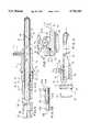
- FIG. 4is an elevational view of the FIG. 1 cutter.
- FIG. 5is an enlarged fragmentary central cross section of the FIG. 4 cutter.
- FIG. 5Ais a fragmentary enlargement of FIG. 5.
- FIG. 5Bis an enlarged fragment of FIG. 5 showing in cross-section a modified tool fragment, the modification including an annular seal interposed between the fixed and rotating hubs of the tool.
- FIG. 6is an enlarged fragmentary partially broken view of the FIG. 4 cutter.
- FIG. 7is an enlarged fragment of FIG. 5 showing in cross section a handpiece fragment for resiliently retaining the tubular mounting hub of the tubular outer housing.
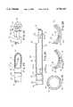
- FIG. 8is a fragmentary exploded view of the FIG. 1 handpiece and cutter, showing same positioned prior to insertion of the rear end of the cutter into the front end of the handpiece.
- FIG. 9is an elevational view similar to FIG. 8.
- FIG. 10is an elevational view similar to FIG. 9 but showing the cutter and handpiece engaged in an operating position.
- FIG. 11is a fragmentary view of the outer tube of the cutter.
- FIG. 12is a sectional view substantially taken on the line 12--12 of FIG. 11.
- FIG. 13is a central cross-sectional view substantially taken on the line 13--13 of FIG. 11.
- FIG. 14is a right end view of the FIG. 13 outer tube.
- FIG. 15is a fragmentary elevational view of the cutter outer tube of FIGS. 11-14 taken generally along the line 15--15 of FIG. 12.
- FIG. 16is a pictorial view of the tubular mounting hub of the outer housing of the FIG. 4 cutter.
- FIG. 17is a central cross-sectional view thereof.
- FIG. 18is an enlarged fragment, indicated at 18--18 of FIG. 17.
- FIG. 19is a pictorial view of a drivable rotor hub of the inner rotor of the FIG. 4 cutter.
- FIG. 20is an elevational view of the inner rotor of the FIG. 4 cutter.
- FIG. 21is an enlarged central cross sectional view substantially taken on line 21--21 of FIG. 20.
- FIG. 22is an elevational view of the inner tube of the FIG. 20 inner rotor, taken from the bottom thereof in FIG. 20.
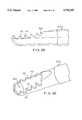
- FIG. 23is an enlarged fragment of the forward end portion (rightward in FIG. 20) of the FIG. 20 and 22 rotatable inner tube.
- FIG. 24is a view similar to FIG. 23 but taken from the opposite side thereof, namely from the bottom in FIG. 20 and showing an enlarged fragment of FIG. 22.
- FIG. 25is a central cross sectional view of the FIG. 23 inner tube forward end portion taken substantially on the line 25--25 of FIG. 22.
- FIG. 26is a transverse cross sectional view substantially taken on the line 26--26 of FIG. 25.
- FIG. 27is an enlarged fragmentary transverse cross sectional view substantially taken on the line 27--27 of FIG. 25.
- FIG. 28is an enlarged fragmentary transverse cross sectional view substantially taken on the line 28--28 of FIG. 25.
- FIG. 29is an enlarged fragmentary elevational view of the forward end of the fixed outer tube generally similar to the orientation of FIG. 13 but taken from the opposite side thereof and showing a modification of the cutting window.
- FIG. 30is a pictorial view of the modified FIG. 29 device.
- FIG. 31is a front view of a pump cassette of the kind shown installed in pumping position on the FIG. 1 pump console.
- FIG. 32is a rear view of the FIG. 31 cassette.
- FIG. 33is a pictorial view of the FIG. 31 cassette taken from the angle to show the top, left side and front thereof.
- FIG. 34is a similar pictorial view of the rear of the FIG. 33 cassette showing primarily the rear and left side thereof.
- FIG. 35is a fragmentary front view of the FIG. 1 console showing the peristaltic pump mounting plate with the FIG. 1 and 31 cassette removed.
- FIG. 36is a sectional view substantially taken on the line 36--36 the FIG. 35 with the cassette installed on the console.
- FIG. 37is a view similar to FIG. 36 but with a pump cassette installed in pumping position on the console mounting face.
- FIG. 38is a cross-sectional view substantially taken on the line 38--38 of FIG. 35 with the cassette installed on the console.
- An irrigation cutter system 10(FIG. 1) comprises a motorized handpiece 11 removably supporting and driving a tool 12 insertable into a surgical site SS for working (e.g. cutting) patient tissue in the surgical site.
- the system 10further includes a console 13 preferably located remote from the handpiece 11 and surgical site SS and a tube set 14 removably connectable with the console 13 and cooperable therewith for pumping irrigation liquid from a conventional irrigation liquid source, such as a conventional bag IB, to the handpiece 11.
- the handpiece 11may be substantially conventional and, for example, similar to cutter handpieces marketed by Stryker Corporation under the trademark HUMMER I.
- the handpiece 11includes a power rotation source (e.g. electric motor), 15 indicated schematically in dotted lines in FIG. 1, contained in a hand held casing 20.
- the handpieceis supplied operating power for its powered rotation source 15 from any convenient power source schematically indicated at PO, such as a conventional electric power source of the type used to operate conventional surgical powered handpieces.
- the handpiece 11is here provided with an internal suction path by which it can apply suction to the tool 12 in a substantially conventional manner, from a suitable suction source SU, as schematically indicated in dotted line in FIG. 1.
- the power source PO and suction source SUmay be connected to the handpiece 11 in any conventional manner, as in FIG.
- the power source POcan be controlled (e.g. turned on and off or varied) in any conventional manner, either directly by the user, or, as indicated schematically by the dotted line at 22, by suitable controls on the console 13 and operable by the user.
- FIGS. 2 and 3schematically show the basic parts of the tool 12.
- the tool 12here comprises a tubular radially outer housing 30 including a tubular mounting hub 31 for fixed but releasable mounting on the forward portion of the casing 20 of the handpiece 11 and an outer tube 32 fixedly projecting forward from the mounting hub 31.
- the mounting hub 31 and outer tube 32have communicating coaxial bores 33 and 34 defining a common radially outer passage 35.
- the tool 12further includes a tubular radially inner rotor 40 including a rotor hub 41 rotatably drivable by the power rotation source 15 of the handpiece 11 (FIG. 1), and an inner tube 42 fixedly projecting forward from the rotor hub 41.
- the rotor hub 41 and inner tube 42have communicating coaxial bores 43 and 44 defining a common radially inner fluid passage 45.
- the inner tube 42is rotatably housed in the outer tube 32 and associated outer tubular mounting hub 31, extending axially from substantially the front (right in FIGS. 2 and 3) end of the outer tube 32 rearwardly (leftwardly in FIGS. 2 and 3) to the outer tubular mounting hub. 31, to coaxially fixedly engage the rotor hub 41.
- the forward ends of the outer and inner tubes 32, 42are at least partially closed (here providing an end thrust bearing effect therebetween), and the front end portions of such outer and inner tubes 32, 42 are each provided with sidewardly and/or radially opening, circumferentially alignable, patient tissue engaging windows, namely an outer window 46 and an inner window 47.
- at least one window 46 or 47has a cutting edge for cutting patient tissue upon rotation of the inner tube 42 within the outer tube 32. The rotation of the inner tube 42 with respect to the outer tube 32 thus periodically substantially radially aligns the inner window 47 with the outer window 46 and allows, at that time, communication between the inner fluid passage 45 and outer window 46.
- the rotor hub 41as schematically shown in FIGS. 2 and 3, has a hole 52 opening from the bore 43 which communicates through the handpiece 11 with the suction source SU as schematically shown in, and discussed above with respect to, FIG. 1.
- the tool 12in its embodiment here shown, is substantially similar to conventional endoscopic suction cutters.
- the hollow outer housing 30its mounting hub 31 (FIGS. 6 and 16-18) is conveniently constructed as a molded plastics member and is substantially rigid.
- the mounting hub 31externally comprises a substantially cylindrical rear portion 53, an annular groove 54, a circumferential rib 55 and an elongate, somewhat forwardly tapering, forward portion 56.
- the annular groove 54is occupied by a resilient seal ring, here a conventional O-ring 57, which protrudes radially outwardly therefrom for sealing engagement against a bore periphery in the front end, or chuck portion, 61 (FIG. 7) of the handpiece 11, for preventing leakage of liquid from the surgical site rearward along the outside of the mounting hub into the handpiece 11.
- chuck portion 61 of the handpiece 11is shown somewhat schematically to more clearly illustrate the features of the invention.
- the tool 12is chucked in the handpiece chuck 61 by displacing axially the outer chuck part 67 rearward against a spring 66 back by the handpiece casing 20 (FIG. 7).
- the chuck portion 61includes a bore 62 which then receives the rear portion 53 of the fixed mounting hub 31 (as well as the portion of the inner rotor 40 to the rear thereof). Rearward displacement of the tool 12 with the respect to the chuck portion 61 is positively stopped by abutment of the rear face of the circumferential rib 55 against a forward facing step 63 defining the rear end of a forward opening recess 64 communicating with the forward end of the bore 62.
- the chuck 61here illustrated includes a latch member 65 (here for example a ball) normally cammed radially inward by a ramp on the surrounding outer chuck part 67 with part 67 normally urged forward by the spring 66.
- a latch member 65here for example a ball
- the ball 65can float radially out beyond the perimeter of the tool ridge 55.
- the ridge 55easily pushes the ball 65 radially outward out of the way to allow such ridge 55 to move into rearward abutment with the chuck step 63.
- the front edge of the circumferential rib 55is provided with circumferentially spaced substantially spherical notches 71 (FIGS. 6, 7 and 16) shaped and sized to receive the rear, radially inner portion of the ball 65, so as to urge the tool 12 rearward against the chuck step 63 and retain the tool 12 axially and circumferentially fixed in place in the chuck.
- the notches 71prevent inadvertent rotation of the tool mounting hub 31 within the handpiece 11 due to interference with the ball 65 with the unnotched portions 72 of the forward edge of the circumferential rib 55.
- one of the notches 71namely one indicated at 71A in FIG. 16, is circumferentially elongate to permit limited angular displacement of the mounting hub 31 with respect to the handpiece 11, if the circumferentially elongate notch 71A is the one engaged by the ball 65.
- more than one radially inwardly resiliently biased ball 65may be supplied and in the embodiment shown, three such balls are preferably provided in evenly circumferentially spaced (e.g. 120°) relation. As seen in FIG. 16, two circumferentially spaced elongate notches 71A are provided in the circumferential rib 55.
- the mounting hub 31has a substantially radially outward extending hollow fitting, here in the form of a nipple 73 (FIGS. 5, 6 and 16), near the front end thereof and spaced forward from the circumferential rib 55 and handpiece chuck portion 61 (FIG. 10).
- the fitting 73includes a through passage 74 for irrigation liquid, extending through the radially outer end of the nipple 73 and thence radially inward therefrom into the central bore 33 of the mounting hub 31. See also FIG. 17.
- the outer end of the nipple 73is connectable to communicate with an outflow hose portion, hereafter described at 204, of the tube set 14 (FIG. 1).
- the front end of the bore 33is chamfered as indicated at 75 in FIG. 17 to facilitate installation of the rear end of the outer tube 32 rearwardly into the bore 33 of the mounting hub 31 to allocate same therein in the manner indicated in FIGS. 5 and 6.
- the outer tube 32(FIGS. 11-15) comprises an elongate cylindrical rearward portion 80 from which forwardly coaxially extends a substantially shorter hollow tubular nose piece 81.
- the nose piece 81has slightly lesser inner and outer diameters than the elongate cylindrical rearward portion 80 and is joined thereto by any convenient and conventional means, for example, integrally, as by radially inwardly deforming the nose piece 81, or by laser welding or the like of initially separate pieces 80 and 81.
- the joinderdefines circumferential external and internal steps 82 and 83 (FIG. 13). While the front end of the nose piece 81 may be configured as desired, in the embodiment shown it is convexly rounded forward in a generally spherical manner as indicated at 84.
- the nose piece 81can be configured to perform a variety of surgical, patient tissue working operations, in the particular unit shown, the nose piece 81 is provided with a sloped planar relief defining the angled shearing outer window 46, same being provided with a sharp shearing edge 85 for shearing coaction with the above mentioned inner window 47 of the inner tube 42 hereafter discussed.
- the radial interior diameter reduction, or necking in, of the nose piece 81 with respect to the rearward cylindrical portion 80provides a close radial shearing fit with the exterior of the front portion of the inner tube 42.
- the elongate cylindrical rearward portion 80 of the outer tube 32includes an irrigation liquid inlet port 90 (FIGS. 11 and 12) axially positioned to align with and be centered on the irrigation liquid through passage 74 of the nipple 73, when the mounting hub 31 is assembled on the outer tube 32.
- the irrigation liquid inlet port 90is preferably substantially D-shaped, with the straight edge of the D-shape at the forward end of the port 90 and the curved portion of the port 90 extending rearward therefrom.
- the hole 90is preferably formed in the outer tube 32 by wire EDM or, any other convenient means, such as by transverse (chordal) milling, with an appropriately shaped milling wheel perimeter cross section.
- the substantially D-shaped configuration of the post 90facilitates snug telescoping of the rigid plastics mounting hub 31 over the rear end portion of the outer tube 32 during assembly by reducing any tendency of the edges of the hole 90 to gouge the inside of the mounting hub 31 during relative axial motion therebetween as assembly is being carried out.
- a heated metal outer tube 32is pressed coaxially forward or rearward into a somewhat undersized bore 33 in a thermoplastics material mounting hub 31, which provides, after the metal tube cools, a rigid fixed coaxial joinder between tube 32 and hub 31.
- insertion of a heated metal outer tube 32tends to soften the engaged portion of the thermoplastics mounting hub 31 to allow easy pressed insertion of tube 32 into mounting hub 31, whereafter cooling of the tube 32 allows the mounting hub 31 to recontour its inner bore 33 to closely fit and harden about the cooled metal tube.
- the knurlingis extendably over the entire area in contact with the hub 31.
- the rotor hub 41(FIGS. 19-21) has a preferably cylindrical, rear opening coaxial recess 100.
- the rear part of the recess 100has diametrally opposed rear opening notches 101 (here two pair thereof) separated by rear extending fingers 102.
- the rear ends of fingers 102are preferably rounded, at least in their radially outer parts and in the rear end portions of the notches 101.
- a coil compression spring 103(FIG. 4) is received in and protrudes rearwardly (when at rest) from the recess 100 peripherally walled by the fingers 102.
- the front end 104 of the shaft of the powered rotation source 15inserts into the rotor hub recess 100 (FIG. 4) to compress the spring and thereby urge the inner rotor 40 forward with respect to the housing 30.
- a diametral cross-pin 105has outer ends received in diametrally opposed ones of the notches 101 for rotatably driving the circumferentially flanking ones of the fingers 102 and thereby rotating the inner rotor 40.
- the suction hole 52preferably is substantially D-shaped, as seen in FIG. 21, with the flat edge 110 thereof rearmost and separated from the rear recess 100 by a transverse wall 111 which may thus be diametral, flat, and relatively thin.
- the suction hole 52extends diametrally through the rotor hub 41 and the rear end portion of the inner tube 42 extends rearwardly part way into the suction hole 52 for direct communication of the suction bore 44 of the inner tube 42 with the transverse suction hole 52, and thereby with the suction source SU when the tool 12 is chucked in the handpiece as seen in FIG. 1.
- the inner tube 42comprises an elongate substantially cylindrical rearward portion 120 carrying a coaxial front end portion 121, which in a particular unit shown is closed except at the front portion of the window 47, the latter being formed in the elongate cylindrical portion 120, as seen in FIGS. 23 and 25.
- the interior surface of the elongate cylindrical portion 120defines the bore 44 and is substantially cylindrical, and hence of substantially constant diameter, throughout its length.
- the elongate intermediate outer periphery 122 of the inner tube 42is of diameter reduced from, but coaxial with, the rear and front outer peripheral portions 123 and 124 of the periphery 122.
- Rear and front portions 123 and 124act as rear and front radial thrust bearings, respectively, to rotatably support the inner tube 42 within the outer tube 32.
- the front radial thrust bearing portion 124is circumferentially interrupted by a longitudinal irrigation liquid channel 130 which communicates from the intermediate outer peripheral portion 122 of the inner tube 42 substantially to the inner tube front end.
- An irrigation liquid port 131(FIGS. 23-25) extends through the peripheral wall of the front outer peripheral portion 124 and communicates between the bore 44 of the inner tube and the longitudinal irrigation liquid channel 130.
- the port 131is centered circumferentially on the channel 130 and both are diametrically opposed to the window 47.
- the port 131opens through the irrigation liquid channel 130 near the front end thereof and is spaced slightly rearward from the rounded front end portion 121.
- the channel 130is conveniently an axially elongate chordal flat in the outer periphery of the forward portion 124, which flat 130 extends rearward somewhat into the intermediate peripheral portion 122 of the inner tube and is of sufficient radial depth as to flatten the periphery of the reduced diameter intermediate portion 122.
- the port 131 and channel 130each can be formed by any convenient means, e.g. EDM or a simple tangential grinding or milling pass across the periphery of the inner tube.
- the port 131is conveniently formed by a chordal flat 132 incised sufficiently deeply into the periphery of the inner tube 42 as to open into the bore 44.
- the chordal flat 132is circumferentially somewhat wider than, and axially much shorter than, the chordal flat 130.
- window 47of various forms are contemplated, in the embodiment shown in FIGS. 23 and 25, the window 47 through most of its length extends substantially along a chordal plane of the inner tube 42 and occupies close to but less than half the circumference of the inner tube 42. Also in the embodiment shown in FIGS. 23 and 25, the chordal edges of the window 47 are provided with teeth 133 spaced longitudinally therealong.
- the rear portion 123 of the inner tube 42is telescopingly fixed in the front opening bore 43 of the rotor hub 41, as shown in FIG. 5, by any convenient means, for example in the manner above described with respect to fixing of the outer tube 32 in the mounting hub 31.
- the rotor hub 41is preferably of a thermoplastic material for receiving the heated rearward portion 123 of the inner tube 42 to, upon cooling, fixedly grip the latter.
- the rearwardmost part of the inner tube rear portion 123may be surface textured, as by knurling 134 (FIG. 22), if desired.
- the tool 12can be assembled by simply inserting the inner tube 42 forwardly into the open rear end of the outer tube 32 and its surrounding mounting hub 31, in the manner generally indicated in FIGS. 4 and 5.
- the front end portion 124 of the inner tube 42is supported by rotating bearing contact of its front outer periphery 124 by the inward stepped nose piece 81 of the outer tube 32 across the bearing clearance gap 135 of approximately 0.001 inch.
- the rearward portion 123 of the inner tube 42is supported rotationally by the rear end portion of the outer tube 32 across a bearing clearance gap 136 of approximately 0.0035 inch.
- the irrigation liquid inlet port 90 of the outer tube 32supplies irrigation liquid radially inward to an annular fluid passage 140 having a radial thickness of about 0.007 inch. Irrigation liquid flow is represented by the arrows in FIG. 5A and passes forward through the annular flow passage 140, then through the longitudinal irrigation liquid channel 130 formed by the corresponding chordal flat, and then forward beyond the step 83 in the outer tube 32 and radially inward through the port 131 into the interior of the inner tube 42.
- the assembled tool 12is chucked, as above discussed, with the tool 12 circumferential rib 71 trapped behind the balls 65 (FIG. 7) to hold the outer housing 30 of the tool 12 fixed in the handpiece chuck 61 and wherein the rear end of the rotor hub 41 and its spring 103 engage the rotatable shaft 104 and its drive pin 105 in the manner discussed above with respect to FIG. 4, for rotating the inner rotor 40 with respect to the outer housing 30 of the tool 12.
- Irrigation liquid flowpasses radially inward through the port 131 in the inner tube 42 and into the forward portion of the interior thereof opposite the windows 46 and 47. If suction is not applied to the inner tube 42, the irrigation liquid then flows out through the rotating inner tube window 46 and fixed outer tube window 47 into the surgical site SS for supplying the latter with irrigation liquid.
- the handpiece 11itself may be provided with the user operator control for controlling rotation of the tool 12 and/or suction in a conventional manner and for this purpose a user thumb actuable push button control 141 is shown in FIG. 8.
- FIGS. 29 and 30show a modified cutting window 46A of the fixed outer tube wherein the opposite sides of the window 46A of the outer tube 32A have a series of notches 142 formed therein, leaving the sides of the modified window 46A defined by a plurality of teeth separated by such notches 142.
- the teeth 142coact with the teeth 133 in the window 47 of the rotating inner tube 42. It has been found by the Applicant that the toothed (at 143) window 46A of the modified outer tube 32A provides a more aggressive cutting action than the untoothed window 46 of the outer tube 32 of FIG. 15.
- Irrigation liquid flow rearward from the irrigator inlet port 90has not been significant, and thus is believed a result of the path of least resistance to irrigation flow being forward from the port.
- a modificationis contemplated which, as shown for example in FIG. 5B, provides an annular seal member 144 (e.g. of Teflon(TM) or other conventional seal material) sealingly interposed between the fixed housing 30B and inner rotor 40B (here between the opposed ends of the fixed and rotating hubs 31B and 41B), behind the port 90 (FIG. 5).
- annular seal member 144e.g. of Teflon(TM) or other conventional seal material
- the console 13(FIG. 35-38) includes a case 151 and a mounting plate 150 which forms a portion (the left front portion in FIG. 1) of the case 151.
- the mounting plate 150is preferably of a rigid molded plastics material.
- the mounting plate 150has a motor 152 (FIG. 37) mounted to extend fixedly rearwardly therefrom.
- the motor 152is fixed on the mounting plate 150 through any convenient means, here including a fixed rigid carrier member 153.
- the motor 152has a rotatable shaft 154 extending forward through a hole 155 in the mounting plate 150.
- a peristaltic pump rotor 160is fixed on the shaft 154 for rotation therewith in front of the mounting plate 150.
- the rotor 160comprises axially opposed, preferably identical, generally triangular, front and rear roller carriers 161 and 162 (FIG. 37).
- the roller carriers 161 and 162each comprise a substantially radially extending, generally triangularly plate 163 and plural (here 3) pairs of coaxially opposed stub shafts 164.
- the carriers 161 and 162are of molded plastic and the stub shafts 164 are recessed at their opposed free ends to minimize the amount of plastics material required.
- Each coaxially opposed pair of stub shafts 164rotatably supports a generally spool-shaped, coaxial, peristaltic pump roller 165.
- the roller carriers 161 and 162are fixed on the shaft 154 by any convenient means, for example by sandwiching axially between diametral through pins 170 fixedly diametrally extending from the motor shaft 154 adjacent front and rear ends of the shaft and engaging corresponding diametral depressions in the axially opposite sides of the plates 163. In this way, the carriers 161 and 162 are held against axial separation so as to reliably rotatably support the rollers 165 and are positively rotatably driven by the motor shaft 154 and thereby for orbiting the pump rollers 165 by rotation of the motor shaft 154.
- rotation of the motor shaft 154in response to energization of the motor 152, rotates the peristaltic pump rotor 160 and thereby orbits the rollers 165 for peristaltic pumping with respect to the peristaltic pumping portion of the tube set hereinafter discussed.
- the front end of shaft 154may be recessed and the front (outer shaft end) pin may be diametrally prefixed in an axial plug 169.
- the carriers 161, 162 and rollers 165may first be installed on the motor shaft 154. Then, the pinned plug 169 is axially inserted and fixed (e.g. by adhesive) in the recessed front end of the motor shaft 154, to fix the carriers 161, 162 on the motor shaft 154.
- the mounting plate 150has a forward step 171 spaced below the pump shaft 154 (FIG. 35) with a concave semi-circular hollow 172 below the rotor 160 and sized and shaped to loosely accommodate the orbiting rollers 165.
- An arcuate cam 173protrudes fixedly forward from the mounting plate 150.
- the cam 173is semi-circularly concave toward the rotor 160 and hence longitudinally (in FIG. 35 downward) along the mounting plate 150.
- the concave face 174 of the cam 173faces toward and extends circumferentially close along just outside the orbit of the rollers 165 of the pump rotor 160.
- the front face 175 of the cam 173is a sloping ramp-like surface angled to face forward and longitudinally away from the rotor 160 (upward in FIG. 35) for purposes appearing hereafter.
- the mounting plate 150(FIG. 35) has parallel, longitudinally extending (extending vertically in FIG. 35), laterally spaced slots 180 therethrough.
- the bottom portions of the slots 180are spaced on opposite sides of the cam 173 and extend at least to the bottom thereof (here slightly below same). Substantially at the level of the top of the cam 173, the slots 180 widen away from each other to form widened mouths 181.
- Recesses 182 in the front face of the mounting plate 150are well spaced above the cam 173 and extend upward in slightly vertically overlapping fashion above the slots 180.
- the recesses 182are laterally spaced from each other and laterally spaced inboard of the slots 180.
- the space between the recesses 180is approximately the width of the cam 173, here slightly greater.
- the recesses 182have laterally opposed, laterally inwardly projecting, wedge shaped portions 183, including laterally inward and upward facing, angled ramps 184 terminating in downward facing steps 185.
- the mounting plate 150also has laterally spaced, parallel, longitudinally aligned, guide grooves 186 laterally spaced closer to the recesses 182 than to each other, longitudinally overlapping both the recesses 182 and slots 180, and overlying, in vertically spaced relation, the cam 173.
- the tube set 14includes a cassette 190 (FIGS. 1 and 31-34).
- the cassette 190has a body 191 having longitudinally spaced top and bottom ends 192 and 193 and laterally spaced sides 194.
- the body 191has a plate-like front wall 195 bounded by the ends 192 and 193 and sides 194.
- the body 191includes a concave backing wall 200 (FIGS. 32 and 34) which extends rearward from the front wall 195 thicknesswise of the body 191.
- the concave backing wall 200is semi-circular and opens concavely toward one end of the body 191, here the bottom end 193.
- the cassette body 191is provided with plural reenforcing ribs 212 extending rearward from the front wall 195 to provide adequate strength to the body 191 while limiting the amount of material required.
- Such bodyis preferably formed by molding of a suitable plastics, hardenable material.
- a peristaltic pumping hose 201(FIG. 32) has a pumping portion 202 backed by the concave backing wall 200 and inflow and outflow portions 203 and 204 respectively extending from the cassette 190 and flanking the pumping portion 202.
- the inflow portion 203 of the pump hose 201is provided with a suitable connector 210 at its free, upper end, for connection in a conventional manner to a irrigation liquid source such as the irrigation liquid bag IB in FIG. 1 and may be provided with a conventional removable clamp 211 for controlling flow from the bag IB.
- the inflow hose portion 203is led down into the cassette body 191 through a hole 205 in the cassette body top wall 192.
- An L-shaped keeper bar 218(FIGS. 32 and 34) fixedly extends from one side wall 194 of the body 191 (the left side wall in FIGS. 32 and 34) intermediate the top most two lateral ribs 212 and opens forward toward the hose portion 203 to prevent its rearward escape from the adjacent notches 213.
- the inflow hose 203is led through notches 213 in various of the ribs 212 down and to one side (the left in FIG. 32) of the downward opening concave backing wall 200 and sealingly and fixedly connects to an elbow 214 at one of the notches 213 in the adjacent rib 212.
- the other end of the elbow 214points laterally into the space below the downwardly concave backing wall 200 and sealingly and fixedly connects to the left (in FIG. 32) end of the flexible peristaltic pumping hose 202.
- Opposed slightly rearward converging steps 217extend rearward adjacent the corresponding notches 213 in the lower left (FIGS. 32 and 34) corner of the body 191 where the hoses 203 and 202 fixedly and sealingly interconnect by sleeving over the grooved ends of the elbow 214.
- the convergent pairs of steps 217each form an undercut into which the corresponding end portion of the corresponding hose 203 or 202 is forcibly and resiliently forwardly pressed at a point where the corresponding hose passes over an annularly grooved portion of the elbow 214, so as to frictionally and through an interference fit tend to prevent rearward escape of the elbow 214 and corresponding hose ends of the hoses 202 and 203 out of the body 191.
- a straight line fitting 215fixedly and sealingly connects the hose portions 202 and 204 (here at the right side of the body 191 as seen from the rear in FIG. 32).
- a preferably integral, U-shaped undercut spring clip 216extends rearward from the cassette front wall 195, as seen in FIGS. 32 and 34.
- the spring clip 216grips snugly, in snap fit fashion, the soft deformable hose pumping portion 202 where it surrounds a grooved portion of the straight line fitting 215.
- the fitting 215is thus fixedly held in place on the cassette body 190.
- the outflow hose 204extends laterally from the cassette body 191 by means of another notch 213 rearward opening in the corresponding side 194 of the cassette body.
- the cassette 190has laterally spaced legs 220 laterally flanking the concave backing wall 200 (FIG. 34) and spaced on opposite sides thereof.
- the legs 220are located between the ends 192 and 193 of the body 191 adjacent the central portion of the backing wall 200.
- the legs 220extend rearward from the body sides 194. Feet 221 on the rear ends of the legs 220 extend laterally (here outwardly) therefrom for blocking forward displacement of the cassette 190 away from the mounting plate 150 of the console as hereafter discussed.
- the cassette 190further has a laterally spaced resilient leaf spring-like arms 222 extending rearward from the body 191 and angled laterally rearwardly and away from each other.
- the armshave rear tips 223 for blocking longitudinal displacement of the cassette 190 with respect to the console mounting plate 150.
- the laterally outer faces of the arms 222are preferably textured as indicated at 224 (for example by means of grooves or ridges transverse to the length of the arms) to facilitate gripping between the thumb and a finger of the user for squeezing, and thereby bending, the arms 223 laterally toward each other to thereby bring the tips 223 laterally closer to each other.
- the arms 222are molded integrally with the body 191 and connect therewith at the front face 195, the arms 222 extending rearward in an elongate, angled fashion so as to protrude and somewhat beyond the rear extent of the body 191.
- the body sides 194are necked in laterally toward each other as indicated at 225 to form laterally outwardly concave recesses, such that the arms 222 are contained laterally in such recesses 225 and their tips 223 are, at rest, substantially closer together laterally than are the feet 221.
- Holes 219 in the plate-like front wall 195 of the body 191are located in front of the above described spring clip 216, rearward convergent step pairs 217 and L-shaped keeper bar 218, as indicated in FIGS. 31 and 33, and are here left by special mold inserts (not shown) which are placed to form the spring clip 216, step pairs 217 and L-shaped keeper bar 218 during the molding of the cassette 190.
- the cassette body 191further includes a pair of parallel, longitudinally (vertically in FIG. 34) aligned, guide ridges 230 which extend rearward from the rear plane of the cassette body 191.
- the guide ridges 230are rearward extensions of the sides 194 at the minimum separation of such sides in the recesses 225.
- the guide ridges 230are thus, in the embodiment shown, flanked at least at their top portions by the arms 222, as seen in FIG. 32.
- the concave backing wall 200 in its major central portionhas a relieved and sloped rear edge 233, which is sloped to face rearward and downward (in FIG. 32) at an angle complementary to the sloped front face 175 of the arcuate cam 173 on the mounting plate 150 of the console.
- the sloped relieved rear edge 233extends upward and rearward into ones of the reenforcing ribs 212 which converge toward and back the top of the concave backing wall 200.
- the relieved sloped portion of the rear edge 233 of the concave backing wall 200extends almost the entire width thereof, in the embodiment shown ending at 234 at a sufficient lateral width to clear the lateral ends of the arcuate cam 173 on the mounting plate 150 of the console.
- the central portion 240 (FIG. 32) of the cassette bottom 193is open to clear the orbiting pump rollers 165.
- a convexly rounded portion 241 of the cassette plate-like front wall 195extends down below the cassette bottom 193 to cover the orbit of the pump rollers 165 and to fit snugly in a front edge recess 242 (FIGS. 35 and 36) of the hollow 172 at the bottom of the mounting plate 150 of the console.
- the tube set 14 and tool 12are each prepackaged, disposable, single use, presterilized (by the manufacturer) devices, the handpiece 11 is sterilizable, and the handpiece 11 and console 13 are reusable, multiple use devices.
- the console 13Prior to use, the console 13 is located in the surgical operating room remote from the operating table (or other patient support) and is connected to a suitable electric power source EP (FIG. 1) at least for powering the peristaltic pump motor 152, as well as any other control functions that may be provided, e.g., as indicated by the dotted lines 22 and 23, control of the handpiece power source PO and suction source SU.
- a suitable electric power source EPFIG. 1
- the tube set 14is readied for use (typically by removal from a sterile package).
- the cassette 190can then be installed on the mounting plate 150 of the console 13. To that end, the cassette 190 is moved forward into contact with the front of the mounting plate 150 with the cassette feet 221 entering the mouths 181 of the mounting plate slots 180. In this position, the rear of the cassette body 191 abuts the front face of the mounting plate 150, the tips 223 of the cassette arms 222 lie in the upper portions of the mounting plate recesses 182 above the wedge shaped portions 183, the cassette guide ridges 230 lie in the upper portions of the mounting plate guide grooves 186 and the cassette concave backing wall sloped rear edge 233 is spaced above the mounting plate arcuate cam 173.
- the cassette legs 220move downward in the mounting plate slots 180 below the mouths 181 thereof with the feet 221 trapped behind the mounting plate.
- the sloped front face 175 of the mounting plate arcuate cam 173cams the hose pumping portion 202 forward onto the center of the rollers 165 (FIG. 37), thus insuring the pumping hose portion 202 does not get caught between the rollers 165 and the mounting plate 150.
- the tips 223 of the arms 222 of the cassette 190ride the ramps 184 downward and inward, and finally spring laterally outwardly apart to lodge snugly under the mounting plate steps 185 to thereby lock the cassette 190 against unintended upward movement along the mounting plate 150.
- the downward movement of the cassette 190 on the mounting plate 150is in part guided by movement of the cassette guide ridges 230 downward in the mounting plate guide grooves 186 to a lower position therein.
- the orbit of the pump rollers 165is covered in front by the plate-like front wall 195 and convex rounded portion 241 thereof, of the cassette body 191, with the bottom edge of the convexly rounded portion 241 snugly received in the front edge recess 242 of the mounting plate hollow 172.
- the cassette concave backing wall 200is flush with and extends forward from the downward facing arcuate cam concave face 174 of the backing plate 150 to provide an essentially continuous downwardly concave surface overlying the pump rotor 160 as generally indicated in FIGS. 36 and 37. This enables the pump rollers 165 to compress the hose pumping portion 202 against the cassette concave backing wall 200 as indicated in FIG. 37.
- the handpiece 11is connected through the cable 21 to the power and suction sources PO and SU respectively, as seen in FIG. 1.
- a tool 12may then be chucked in the handpiece 11 and the irrigation outflow hose 204 from the cassette 190 may then be connected, as indicated at 73, to the irrigation liquid inflow fitting of the tool 12.
- the outflow hose portion 204may be secured to the body of the handpiece 11 by any convenient releasable clip means, not shown.
- the irrigation liquid inflow hose portion 203may then be plugged on at 210 into a conventional irrigation liquid supply bag IB.
- the peristaltic pumpdefined by the cassette 190 and pump rotor 160 can be operated to supply irrigation liquid to the tool 12 and therethrough to the surgical site SS (FIG. 1).
- the peristaltic pumpcan be operated continuously by continuous energization of its motor 152 or discontinuously by turning on and off its motor 152. Turning on and off of the peristaltic pump motor 152 may be accomplished by means near the surgical site such as a user operated foot switch or the like or by suitable switching on the console 13 in a conventional manner.
- meansmay be provided on the outflow hose 204 to close or open flow therethrough and such means may be provided close to or on the handpiece for convenient use.
- the tool inner rotor 40is rotated by the powered rotation source 15 of the handpiece 11, while the tool housing 30 is fixed with respect to the handpiece outer casing held by the surgeon.
- the rotating inner tube 42thus rotates its inner window 47 repetitively passed the outer window 46 (FIGS. 2-4) of the outer tube 32 to accomplish a shearing type tissue cutting action.
- Tissue workingcan be accomplished with a variety of window configurations at 46, 47, including that shown in FIG. 4.
- a more aggressive tissue cutting actioncan be accomplished by substituting the modified outer tube window configuration at 46A of FIGS. 29 and 30, with its teeth 142 in rotating cutting cooperation with the teeth 133 on the inner tube window 47.
- irrigation flowmay be combined with suction flow (FIG. 2) or used alone to provide irrigation liquid to the surgical site.
- irrigation liquid flow through the fitting 73 and the annular flow space between the inner and outer tubes and thence through the port 131provides irrigation liquid to the inside of the inner tube 42 near its front end and thereby allows outflow of such irrigation liquid to the surgical site SS, through the windows 46 and 47 as they periodically mesh.
- provision of suction rearward through the inner tube 42draws at least some of the irrigation liquid flowing into the inner tube 42 through the hole 131 rearwardly along the inner tube 42 to entrain and thereby retrieve unwanted debris from the surgical site SS.
Landscapes
- Health & Medical Sciences (AREA)
- Heart & Thoracic Surgery (AREA)
- Life Sciences & Earth Sciences (AREA)
- Animal Behavior & Ethology (AREA)
- General Health & Medical Sciences (AREA)
- Engineering & Computer Science (AREA)
- Biomedical Technology (AREA)
- Veterinary Medicine (AREA)
- Public Health (AREA)
- Hematology (AREA)
- Anesthesiology (AREA)
- Vascular Medicine (AREA)
- Surgery (AREA)
- Orthopedic Medicine & Surgery (AREA)
- Molecular Biology (AREA)
- Medical Informatics (AREA)
- Nuclear Medicine, Radiotherapy & Molecular Imaging (AREA)
- Pulmonology (AREA)
- Surgical Instruments (AREA)
- External Artificial Organs (AREA)
Abstract
Description
Claims (21)
Priority Applications (4)
| Application Number | Priority Date | Filing Date | Title |
|---|---|---|---|
| US08/713,434US5792167A (en) | 1996-09-13 | 1996-09-13 | Surgical irrigation pump and tool system |
| US09/093,484US5928257A (en) | 1996-09-13 | 1998-06-08 | Surgical irrigation pump and tool system |
| US09/093,483US6007556A (en) | 1996-09-13 | 1998-06-08 | Surgical irrigation pump and tool system |
| US09/428,144US6342061B1 (en) | 1996-09-13 | 1999-10-27 | Surgical tool with integrated channel for irrigation |
Applications Claiming Priority (1)
| Application Number | Priority Date | Filing Date | Title |
|---|---|---|---|
| US08/713,434US5792167A (en) | 1996-09-13 | 1996-09-13 | Surgical irrigation pump and tool system |
Related Child Applications (2)
| Application Number | Title | Priority Date | Filing Date |
|---|---|---|---|
| US09/093,483ContinuationUS6007556A (en) | 1996-09-13 | 1998-06-08 | Surgical irrigation pump and tool system |
| US09/093,484DivisionUS5928257A (en) | 1996-09-13 | 1998-06-08 | Surgical irrigation pump and tool system |
Publications (1)
| Publication Number | Publication Date |
|---|---|
| US5792167Atrue US5792167A (en) | 1998-08-11 |
Family
ID=24866125
Family Applications (3)
| Application Number | Title | Priority Date | Filing Date |
|---|---|---|---|
| US08/713,434Expired - LifetimeUS5792167A (en) | 1996-09-13 | 1996-09-13 | Surgical irrigation pump and tool system |
| US09/093,483Expired - LifetimeUS6007556A (en) | 1996-09-13 | 1998-06-08 | Surgical irrigation pump and tool system |
| US09/093,484Expired - LifetimeUS5928257A (en) | 1996-09-13 | 1998-06-08 | Surgical irrigation pump and tool system |
Family Applications After (2)
| Application Number | Title | Priority Date | Filing Date |
|---|---|---|---|
| US09/093,483Expired - LifetimeUS6007556A (en) | 1996-09-13 | 1998-06-08 | Surgical irrigation pump and tool system |
| US09/093,484Expired - LifetimeUS5928257A (en) | 1996-09-13 | 1998-06-08 | Surgical irrigation pump and tool system |
Country Status (1)
| Country | Link |
|---|---|
| US (3) | US5792167A (en) |
Cited By (106)
| Publication number | Priority date | Publication date | Assignee | Title |
|---|---|---|---|---|
| US5989210A (en)* | 1998-02-06 | 1999-11-23 | Possis Medical, Inc. | Rheolytic thrombectomy catheter and method of using same |
| US6010477A (en)* | 1996-09-24 | 2000-01-04 | Xomed Surgical Products, Inc. | Surgical blades assembly |
| US6086598A (en)* | 1996-08-29 | 2000-07-11 | Bausch & Lomb Surgical, Inc. | Ophthalmic microsurgical system having color sensor for cassette identification |
| DE19859217A1 (en)* | 1998-12-21 | 2000-07-27 | Wolf Gmbh Richard | Electromotor drive for a surgical tool has a drive unit placed as a first module within a housing that forms a second module |
| US6132448A (en)* | 1998-06-19 | 2000-10-17 | Stryker Corporation | Endoscopic irrigated bur |
| US6312441B1 (en) | 1999-03-04 | 2001-11-06 | Stryker Corporation | Powered handpiece for performing endoscopic surgical procedures |
| US6332886B1 (en) | 1999-02-03 | 2001-12-25 | Synthes (Usa) | Surgical reamer and method of using same |
| US6342061B1 (en) | 1996-09-13 | 2002-01-29 | Barry J. Kauker | Surgical tool with integrated channel for irrigation |
| US20020039544A1 (en)* | 2000-10-04 | 2002-04-04 | Schroeder Kirk S. | Efficient aseptic fluid transfer apparatus and consumable therefor |
| US20020177802A1 (en)* | 1999-05-18 | 2002-11-28 | Moutafis Timothy E. | Fluid jet surgical instruments |
| US20030055404A1 (en)* | 2001-09-17 | 2003-03-20 | Moutafis Timothy E. | Endoscopic rotary abraders |
| US20030083681A1 (en)* | 2001-09-17 | 2003-05-01 | Moutafis Timothy E. | Surgical rotary abrader |
| US20030125660A1 (en)* | 2001-11-21 | 2003-07-03 | Moutafis Timothy E. | Liquid jet surgical instruments incorporating channel openings aligned along the jet beam |
| US6610059B1 (en) | 2002-02-25 | 2003-08-26 | Hs West Investments Llc | Endoscopic instruments and methods for improved bubble aspiration at a surgical site |
| US20030181934A1 (en)* | 2002-03-22 | 2003-09-25 | Gyrus Ent L.L.C. | Powered surgical apparatus, method of manufacturing powered surgical apparatus, and method of using powered surgical apparatus |
| US20030191488A1 (en)* | 2002-04-09 | 2003-10-09 | Braden Robison | Surgical instrument |
| WO2004002331A1 (en)* | 2002-06-29 | 2004-01-08 | Hee-Young Lee | Facial bone contouring device using hollowed rasp provided with non-plugging holes formed through cutting plane |
| US20040010258A1 (en)* | 2002-07-13 | 2004-01-15 | Steven Carusillo | Surgical tool system |
| US20040138687A1 (en)* | 1999-04-29 | 2004-07-15 | Stryker Corporation | Surgical tool system with a handpiece having a valve assembly for regulating the fluid pump connected to the handpiece |
| US6783533B2 (en) | 2001-11-21 | 2004-08-31 | Sythes Ag Chur | Attachable/detachable reaming head for surgical reamer |
| US6783532B2 (en) | 1999-02-02 | 2004-08-31 | Synthes (Usa) | Device for removing bone tissue |
| US20050021075A1 (en)* | 2002-12-30 | 2005-01-27 | Bonnette Michael J. | Guidewire having deployable sheathless protective filter |
| WO2005020826A1 (en)* | 2003-09-03 | 2005-03-10 | Hee Young Lee | Surgical handpiece equipped with couplings for suction and saline solution |
| US20050182432A1 (en)* | 2004-02-18 | 2005-08-18 | Fanton Gary S. | Apparatus and methods for clearing obstructions from surgical cutting instruments |
| US20050203439A1 (en)* | 2002-03-19 | 2005-09-15 | Norbert Heske | Vacuum biopsy device |
| US20060025793A1 (en)* | 2004-08-02 | 2006-02-02 | Karl Storz Endovision | Surgical instrument attachment system |
| US20060264995A1 (en)* | 2004-02-18 | 2006-11-23 | Fanton Gary S | Apparatus and methods for clearing obstructions from surgical cutting instruments |
| WO2008007890A1 (en)* | 2006-07-10 | 2008-01-17 | Medikan Co., Ltd. | Facial bone surgery apparatus for medical |
| US20080208233A1 (en)* | 2006-12-21 | 2008-08-28 | Aaron Barnes | Disposable vitrectomy handpiece |
| US20080234722A1 (en)* | 2006-06-14 | 2008-09-25 | Possis Medical, Inc. | Inferior vena cava filter on guidewire |
| US20080275485A1 (en)* | 2006-04-03 | 2008-11-06 | Possis Medical, Inc. | Guidewire with collapsible filter system and method of use |
| US20080275383A1 (en)* | 2004-08-02 | 2008-11-06 | Weisel Stephen E | Miniature cross stream thrombectomy catheter |
| US20080289181A1 (en)* | 2007-02-06 | 2008-11-27 | Possis Medical, Inc. | Method of manufacturing a miniature flexible thrombectomy catheter |
| US20080300532A1 (en)* | 2004-12-10 | 2008-12-04 | Possis Medical, Inc. | Enhanced cross stream mechanical thrombectomy catheter |
| US20080319341A1 (en)* | 2005-08-10 | 2008-12-25 | C.R. Bard Inc. | Single-Insertion, Multiple Sample Biopsy Device with Integrated Markers |
| US20090043286A1 (en)* | 2007-08-06 | 2009-02-12 | Neotech Products, Inc. | Highly efficient fluid suctioning device |
| US20090088784A1 (en)* | 2007-09-27 | 2009-04-02 | Doheny Eye Institute | Selectable stroke cutter |
| US7537594B2 (en) | 2003-05-01 | 2009-05-26 | Covidien Ag | Suction coagulator with dissecting probe |
| US20090214365A1 (en)* | 2008-02-22 | 2009-08-27 | Norman Gerould W | Method and system for loading of tubing into a pumping device |
| US20100030108A1 (en)* | 2006-10-24 | 2010-02-04 | C.R. Bard, Inc. | Large sample low aspect ratio biopsy needle |
| US20110021946A1 (en)* | 2003-03-29 | 2011-01-27 | C.R. Bard, Inc. | Biopsy needle system having a pressure generating unit |
| US20110077551A1 (en)* | 2009-09-25 | 2011-03-31 | Videbaek Karsten | Charging station for battery powered biopsy apparatus |
| US20110098688A1 (en)* | 2009-10-28 | 2011-04-28 | Bien-Air Holding S.A. | Coupling device between the drive shaft of a surgical instrument and a tool |
| US8002713B2 (en) | 2002-03-19 | 2011-08-23 | C. R. Bard, Inc. | Biopsy device and insertable biopsy needle module |
| US8012117B2 (en) | 2007-02-06 | 2011-09-06 | Medrad, Inc. | Miniature flexible thrombectomy catheter |
| US8012102B2 (en) | 2005-01-31 | 2011-09-06 | C. R. Bard, Inc. | Quick cycle biopsy system |
| US8052615B2 (en) | 2004-07-09 | 2011-11-08 | Bard Peripheral Vascular, Inc. | Length detection system for biopsy device |
| US8162966B2 (en) | 2002-10-25 | 2012-04-24 | Hydrocision, Inc. | Surgical devices incorporating liquid jet assisted tissue manipulation and methods for their use |
| US8162878B2 (en) | 2005-12-05 | 2012-04-24 | Medrad, Inc. | Exhaust-pressure-operated balloon catheter system |
| US8251917B2 (en) | 2006-08-21 | 2012-08-28 | C. R. Bard, Inc. | Self-contained handheld biopsy needle |
| US8262585B2 (en) | 2005-08-10 | 2012-09-11 | C. R. Bard, Inc. | Single-insertion, multiple sampling biopsy device with linear drive |
| US8282574B2 (en) | 2005-08-10 | 2012-10-09 | C. R. Bard, Inc. | Single-insertion, multiple sampling biopsy device usable with various transport systems and integrated markers |
| US8303538B2 (en) | 2007-12-17 | 2012-11-06 | Medrad, Inc. | Rheolytic thrombectomy catheter with self-inflating distal balloon |
| US8430824B2 (en) | 2009-10-29 | 2013-04-30 | Bard Peripheral Vascular, Inc. | Biopsy driver assembly having a control circuit for conserving battery power |
| US8439878B2 (en) | 2007-12-26 | 2013-05-14 | Medrad, Inc. | Rheolytic thrombectomy catheter with self-inflating proximal balloon with drug infusion capabilities |
| US8454532B2 (en) | 2007-12-27 | 2013-06-04 | Devicor Medical Products, Inc. | Clutch and valving system for tetherless biopsy device |
| US8485989B2 (en) | 2009-09-01 | 2013-07-16 | Bard Peripheral Vascular, Inc. | Biopsy apparatus having a tissue sample retrieval mechanism |
| US8485987B2 (en) | 2006-10-06 | 2013-07-16 | Bard Peripheral Vascular, Inc. | Tissue handling system with reduced operator exposure |
| DE102012103153A1 (en)* | 2012-04-12 | 2013-10-17 | Karl Storz Gmbh & Co. Kg | Medical instrument for separating tissue and cartilage |
| US8597205B2 (en) | 2007-12-20 | 2013-12-03 | C. R. Bard, Inc. | Biopsy device |
| US8597206B2 (en) | 2009-10-12 | 2013-12-03 | Bard Peripheral Vascular, Inc. | Biopsy probe assembly having a mechanism to prevent misalignment of components prior to installation |
| US8647294B2 (en) | 2008-03-20 | 2014-02-11 | Medrad, Inc. | Direct stream hydrodynamic catheter system |
| US8690793B2 (en) | 2009-03-16 | 2014-04-08 | C. R. Bard, Inc. | Biopsy device having rotational cutting |
| US8708930B2 (en) | 2009-04-15 | 2014-04-29 | Bard Peripheral Vascular, Inc. | Biopsy apparatus having integrated fluid management |
| US20140276832A1 (en)* | 2013-03-14 | 2014-09-18 | Nadi Salah Hibri | Surgical Device |
| US8845548B2 (en) | 2009-06-12 | 2014-09-30 | Devicor Medical Products, Inc. | Cutter drive assembly for biopsy device |
| US8920419B2 (en) | 2012-11-30 | 2014-12-30 | Gyrus Acmi, Inc. | Apparatus and method for tubeset with drive axle |
| US20150005753A1 (en)* | 2012-03-05 | 2015-01-01 | Wake Forest University Health Sciences | Medical tools with aspiration tips suitable for cataract surgeries and related methods |
| US9173641B2 (en) | 2009-08-12 | 2015-11-03 | C. R. Bard, Inc. | Biopsy apparatus having integrated thumbwheel mechanism for manual rotation of biopsy cannula |
| US9211373B2 (en) | 2011-09-23 | 2015-12-15 | Medtronic Ps Medical, Inc. | Irrigation system and clip for a surgical instrument |
| US9226792B2 (en) | 2012-06-12 | 2016-01-05 | Medtronic Advanced Energy Llc | Debridement device and method |
| US20160066945A1 (en)* | 2014-09-08 | 2016-03-10 | Medtronic-Xomed, Inc. | Tumor margin device |
| US9345541B2 (en) | 2009-09-08 | 2016-05-24 | Medtronic Advanced Energy Llc | Cartridge assembly for electrosurgical devices, electrosurgical unit and methods of use thereof |
| US9358036B2 (en) | 2013-03-12 | 2016-06-07 | Gyrus Acmi, Inc. | Blade positioning device |
| US9387050B2 (en) | 2014-09-15 | 2016-07-12 | Gyrus Acmi Inc. | Surgical system having detachable component and state detection circuit for detection of state of attachment of detachable component |
| US9546662B2 (en) | 2012-11-20 | 2017-01-17 | Smith & Nephew, Inc. | Medical pump |
| US9586023B2 (en) | 1998-02-06 | 2017-03-07 | Boston Scientific Limited | Direct stream hydrodynamic catheter system |
| EP2370005A4 (en)* | 2008-12-05 | 2017-06-07 | Urotech, Inc. | Benign prostatic hyperplasia surgical system featuring mechanical coring probe with live aspiration |
| US9737322B2 (en) | 2014-09-08 | 2017-08-22 | Medtronic Xomed, Inc. | Method for resection of tumors and tissues |
| US9820825B2 (en) | 2015-02-20 | 2017-11-21 | Gyrus Acmi Inc. | Surgical system having plurality of detachably attachable components and circuit for detecting target states of detachably attachable components and performing control based on detected target states, and method for providing surgical system |
| EP3292827A1 (en)* | 2016-09-13 | 2018-03-14 | Biosense Webster (Israel), Ltd. | Debrider with multiple flushing orifices |
| US9955993B2 (en) | 2002-08-08 | 2018-05-01 | Stryker Corporation | Surgical tool system with quick release coupling assembly |
| USD831819S1 (en) | 2016-01-22 | 2018-10-23 | Medline Industries, Inc. | Irrigator |
| US10188456B2 (en) | 2015-02-18 | 2019-01-29 | Medtronic Xomed, Inc. | Electrode assembly for RF energy enabled tissue debridement device |
| US10285673B2 (en) | 2013-03-20 | 2019-05-14 | Bard Peripheral Vascular, Inc. | Biopsy device |
| US10363061B2 (en) | 2002-10-25 | 2019-07-30 | Hydrocision, Inc. | Nozzle assemblies for liquid jet surgical instruments and surgical instruments for employing the nozzle assemblies |
| US10376302B2 (en) | 2015-02-18 | 2019-08-13 | Medtronic Xomed, Inc. | Rotating electrical connector for RF energy enabled tissue debridement device |
| US10456120B2 (en) | 2013-11-05 | 2019-10-29 | C. R. Bard, Inc. | Biopsy device having integrated vacuum |
| US10463350B2 (en) | 2015-05-01 | 2019-11-05 | C. R. Bard, Inc. | Biopsy device |
| US10716612B2 (en) | 2015-12-18 | 2020-07-21 | Medtronic Advanced Energy Llc | Electrosurgical device with multiple monopolar electrode assembly |
| US10874416B2 (en) | 2017-02-02 | 2020-12-29 | Biosense Webster (Israel) Ltd. | Surgical cutting instrument with extended blades |
| US10874552B2 (en) | 2011-07-08 | 2020-12-29 | Doheny Eye Institute | Ocular lens cutting device |
| CN112315542A (en)* | 2019-08-05 | 2021-02-05 | 北京道生济医院管理有限公司 | Hand-held surgical device |
| US11000305B2 (en) | 2017-08-02 | 2021-05-11 | Stryker Corporation | Surgical tool systems, and methods of use thereof |
| US11116483B2 (en) | 2017-05-19 | 2021-09-14 | Merit Medical Systems, Inc. | Rotating biopsy needle |
| US11207130B2 (en) | 2015-02-18 | 2021-12-28 | Medtronic Xomed, Inc. | RF energy enabled tissue debridement device |
| US20220071652A1 (en)* | 2016-07-28 | 2022-03-10 | Covidien Lp | Reciprocating rotary surgical cutting device and system for tissue resecting, and method for its use |
| US11413051B2 (en) | 2017-07-25 | 2022-08-16 | Stryker European Holdings I Llc | Irrigation sleeves for use with surgical systems |
| US20220387064A1 (en)* | 2007-02-05 | 2022-12-08 | Walk Vascular, Llc | Thrombectomy apparatus and method |
| US11793498B2 (en) | 2017-05-19 | 2023-10-24 | Merit Medical Systems, Inc. | Biopsy needle devices and methods of use |
| US11844500B2 (en) | 2017-05-19 | 2023-12-19 | Merit Medical Systems, Inc. | Semi-automatic biopsy needle device and methods of use |
| US20230404653A1 (en)* | 2022-06-21 | 2023-12-21 | Gyrus Medical Limited | Hand-piece for an electrosurgical instrument |
| US12023082B2 (en) | 2017-10-06 | 2024-07-02 | Medtronic Advanced Energy Llc | Hemostatic thermal sealer |
| US12150627B2 (en) | 2019-12-11 | 2024-11-26 | Merit Medical Systems, Inc. | Bone biopsy device and related methods |
| US12295556B2 (en) | 2019-09-27 | 2025-05-13 | Merit Medical Systems, Inc. | Rotation biopsy system and handle |
| US12336731B2 (en)* | 2021-10-22 | 2025-06-24 | Gyrus Acmi, Inc. | High speed burr with flex shaft cooling and improved suction |
Families Citing this family (40)
| Publication number | Priority date | Publication date | Assignee | Title |
|---|---|---|---|---|
| US6171300B1 (en)* | 1997-09-04 | 2001-01-09 | Linvatec Corporation | Tubing cassette and method for cooling a surgical handpiece |
| DE10162933B4 (en)* | 2001-12-20 | 2008-08-14 | Fraunhofer-Gesellschaft zur Förderung der angewandten Forschung e.V. | Device for tissue extraction |
| US20030176881A1 (en)* | 2002-02-26 | 2003-09-18 | Barlev B. Alex | Shaver blade |
| US7887559B2 (en)* | 2002-08-08 | 2011-02-15 | Stryker Corporation | Surgical cutting accessory with encapsulated RFID chip |
| CA2516321A1 (en)* | 2003-02-20 | 2004-09-02 | Kenneth M. Adams | Surgical elongate blade assembly with interchangeable inner member, kit and method relating thereto |
| US7238010B2 (en)* | 2003-04-14 | 2007-07-03 | Stryker Corporation | Surgical irrigation pump and tool system |
| US7753880B2 (en)* | 2004-09-28 | 2010-07-13 | Stryker Corporation | Method of operating a surgical irrigation pump capable of performing a priming operation |
| US7597699B2 (en)* | 2005-07-25 | 2009-10-06 | Rogers William G | Motorized surgical handpiece |
| US8565839B2 (en) | 2005-10-13 | 2013-10-22 | Abbott Medical Optics Inc. | Power management for wireless devices |
| US8380126B1 (en) | 2005-10-13 | 2013-02-19 | Abbott Medical Optics Inc. | Reliable communications for wireless devices |
| US9522221B2 (en)* | 2006-11-09 | 2016-12-20 | Abbott Medical Optics Inc. | Fluidics cassette for ocular surgical system |
| US8414534B2 (en) | 2006-11-09 | 2013-04-09 | Abbott Medical Optics Inc. | Holding tank devices, systems, and methods for surgical fluidics cassette |
| US9295765B2 (en)* | 2006-11-09 | 2016-03-29 | Abbott Medical Optics Inc. | Surgical fluidics cassette supporting multiple pumps |
| US10959881B2 (en) | 2006-11-09 | 2021-03-30 | Johnson & Johnson Surgical Vision, Inc. | Fluidics cassette for ocular surgical system |
| US8491528B2 (en)* | 2006-11-09 | 2013-07-23 | Abbott Medical Optics Inc. | Critical alignment of fluidics cassettes |
| US20110088151A1 (en)* | 2007-04-17 | 2011-04-21 | Semra Peksoz | Firefighter's turnout coat with seamless collar |
| US10596032B2 (en) | 2007-05-24 | 2020-03-24 | Johnson & Johnson Surgical Vision, Inc. | System and method for controlling a transverse phacoemulsification system with a footpedal |
| US10485699B2 (en) | 2007-05-24 | 2019-11-26 | Johnson & Johnson Surgical Vision, Inc. | Systems and methods for transverse phacoemulsification |
| US10363166B2 (en) | 2007-05-24 | 2019-07-30 | Johnson & Johnson Surgical Vision, Inc. | System and method for controlling a transverse phacoemulsification system using sensed data |
| US8162633B2 (en)* | 2007-08-02 | 2012-04-24 | Abbott Medical Optics Inc. | Volumetric fluidics pump with translating shaft path |
| US10342701B2 (en) | 2007-08-13 | 2019-07-09 | Johnson & Johnson Surgical Vision, Inc. | Systems and methods for phacoemulsification with vacuum based pumps |
| US9078964B2 (en) | 2008-08-21 | 2015-07-14 | Sur-Real Industries, Inc. | Pump device, tube device and method for movement and collection of fluid |
| WO2010054145A1 (en) | 2008-11-07 | 2010-05-14 | Abbott Medical Optics Inc. | Surgical cassette apparatus |
| CA2743086C (en) | 2008-11-07 | 2017-12-05 | Abbott Medical Optics Inc. | Automatically pulsing different aspiration levels to an ocular probe |
| EP2373265B1 (en) | 2008-11-07 | 2016-03-09 | Abbott Medical Optics Inc. | Controlling of multiple pumps |
| EP3156012B1 (en) | 2008-11-07 | 2021-10-20 | Johnson & Johnson Surgical Vision, Inc. | Adjustable foot pedal control for ophthalmic surgery |
| AU2009313402C1 (en) | 2008-11-07 | 2015-10-15 | Johnson & Johnson Surgical Vision, Inc. | Automatically switching different aspiration levels and/or pumps to an ocular probe |
| US10349925B2 (en)* | 2008-11-07 | 2019-07-16 | Johnson & Johnson Surgical Vision, Inc. | Method for programming foot pedal settings and controlling performance through foot pedal variation |
| EP2341878B1 (en)* | 2008-11-07 | 2017-06-21 | Abbott Medical Optics Inc. | Semi-automatic device calibraton |
| US9795507B2 (en) | 2008-11-07 | 2017-10-24 | Abbott Medical Optics Inc. | Multifunction foot pedal |
| US8287485B2 (en)* | 2009-01-28 | 2012-10-16 | Olympus Medical Systems Corp. | Treatment system for surgery and control method of treatment system for surgery |
| US9492317B2 (en) | 2009-03-31 | 2016-11-15 | Abbott Medical Optics Inc. | Cassette capture mechanism |
| US8876757B2 (en)* | 2009-11-12 | 2014-11-04 | Abbott Medical Optics Inc. | Fluid level detection system |
| WO2013142009A1 (en) | 2012-03-17 | 2013-09-26 | Abbott Medical Optics, Inc. | Surgical cassette |
| US10113542B2 (en) | 2012-05-24 | 2018-10-30 | Cook Medical Technologies Llc | Peristaltic pump tubing securing system |
| USD809909S1 (en) | 2013-03-15 | 2018-02-13 | Cook Medical Technologies Llc | Tubing clips |
| US9833284B2 (en)* | 2015-02-04 | 2017-12-05 | Biosense Webster (Israel) Ltd. | Pressure-driven irrigation pump |
| CN105944164B (en)* | 2016-07-04 | 2018-04-06 | 宋庆涛 | One-piece flushing aspirator |
| US11185345B2 (en) | 2018-01-31 | 2021-11-30 | Gyrus Acmi, Inc. | Debrider with external irrigation supply channel |
| US12414792B2 (en)* | 2022-08-31 | 2025-09-16 | Medtronic Xomed Llc | Microdebrider with stability interface bushing |
Citations (97)
| Publication number | Priority date | Publication date | Assignee | Title |
|---|---|---|---|---|
| US3568318A (en)* | 1969-05-01 | 1971-03-09 | Sybron Corp | Control for dental handpieces and the like |
| US3618611A (en)* | 1969-03-05 | 1971-11-09 | Julius C Urban | Vacuum rotary dissector |
| US3674024A (en)* | 1970-07-15 | 1972-07-04 | Kidde & Co Walter | Incision irrigator for use during surgical procedures |
| US3678934A (en)* | 1970-08-13 | 1972-07-25 | Stryker Corp | Power osteotome |
| US3732858A (en)* | 1968-09-16 | 1973-05-15 | Surgical Design Corp | Apparatus for removing blood clots, cataracts and other objects from the eye |
| US3844272A (en)* | 1969-02-14 | 1974-10-29 | A Banko | Surgical instruments |
| US3882872A (en)* | 1970-01-05 | 1975-05-13 | Nicholas G Douvas | Method and apparatus for cataract surgery |
| US3912168A (en)* | 1975-01-30 | 1975-10-14 | Teledyne Ind Inc Teledyne Aqua | Irrigation lavage |
| US3945375A (en)* | 1972-04-04 | 1976-03-23 | Surgical Design Corporation | Rotatable surgical instrument |
| US3960466A (en)* | 1975-02-10 | 1976-06-01 | Taylor Edward J | Douche-enema pump |
| US3990453A (en)* | 1973-04-25 | 1976-11-09 | Douvas Nicholas G | Apparatus for cataract surgery |
| US3993054A (en)* | 1975-06-19 | 1976-11-23 | Stryker Corporation | Therapeutic lavage |
| US3995619A (en)* | 1975-10-14 | 1976-12-07 | Glatzer Stephen G | Combination subcutaneous suture remover, biopsy sampler and syringe |
| US3996935A (en)* | 1969-02-14 | 1976-12-14 | Surgical Design Corporation | Surgical-type method for removing material |
| US4011869A (en)* | 1975-08-01 | 1977-03-15 | David Kopf Instruments | Tubular cutting instrument |
| US4014342A (en)* | 1975-04-11 | 1977-03-29 | Concept, Inc. | Vitreous cutter |
| US4138205A (en)* | 1975-12-15 | 1979-02-06 | Hydro Pulse Corporation | Movable stator walls permitting access to tubing in peristaltic pump |
| US4167944A (en)* | 1977-06-27 | 1979-09-18 | Surgical Design Corp. | Rotatable surgical cutting instrument with improved cutter blade wear |
| US4179249A (en)* | 1977-12-07 | 1979-12-18 | Cole-Parmer Instrument Company | Quick loading peristaltic pump |
| US4203444A (en)* | 1977-11-07 | 1980-05-20 | Dyonics, Inc. | Surgical instrument suitable for closed surgery such as of the knee |
| US4210146A (en)* | 1978-06-01 | 1980-07-01 | Anton Banko | Surgical instrument with flexible blade |
| US4239464A (en)* | 1977-10-14 | 1980-12-16 | Polystan A/S | Blood pump |
| US4246902A (en)* | 1978-03-10 | 1981-01-27 | Miguel Martinez | Surgical cutting instrument |
| US4274414A (en)* | 1979-02-21 | 1981-06-23 | Dyonics, Inc. | Surgical instrument |
| US4276023A (en)* | 1979-09-28 | 1981-06-30 | Stryker Corporation | Fluid flow control console |
| US4368734A (en)* | 1978-01-27 | 1983-01-18 | Surgical Design Corp. | Surgical instrument |
| CA1145636A (en)* | 1980-03-10 | 1983-05-03 | Lanny L. Johnson | Surgical instrument suitable for closed surgery such as of the knee |
| GB2076068B (en) | 1980-05-16 | 1983-11-09 | Smith & Nephew Ass | Peristaltic fluid-machines |
| US4512344A (en)* | 1982-05-12 | 1985-04-23 | Barber Forest C | Arthroscopic surgery dissecting apparatus |
| US4516571A (en)* | 1983-03-10 | 1985-05-14 | Smith And Nephew Associated Companies P.L.C. | Medical device, its preparation and use |
| US4548553A (en)* | 1984-09-24 | 1985-10-22 | Ferster Reuben I | Peristaltic pump structure |
| US4552516A (en)* | 1984-06-15 | 1985-11-12 | Cole-Parmer Instrument Company | Peristaltic pump |
| US4559040A (en)* | 1984-10-30 | 1985-12-17 | Pancretec, Inc. | Segmented peristaltic pump chamber |
| US4599055A (en)* | 1985-06-25 | 1986-07-08 | Cobe Laboratories, Inc. | Peristaltic pump |
| US4598710A (en)* | 1984-01-20 | 1986-07-08 | Urban Engineering Company, Inc. | Surgical instrument and method of making same |
| US4601290A (en)* | 1983-10-11 | 1986-07-22 | Cabot Medical Corporation | Surgical instrument for cutting body tissue from a body area having a restricted space |
| US4603694A (en)* | 1983-03-08 | 1986-08-05 | Richards Medical Company | Arthroscopic shaver |
| EP0190000A2 (en)* | 1985-01-23 | 1986-08-06 | BAXTER INTERNATIONAL INC. (a Delaware corporation) | Surgical instrument |
| US4646738A (en)* | 1985-12-05 | 1987-03-03 | Concept, Inc. | Rotary surgical tool |
| US4646736A (en)* | 1984-09-10 | 1987-03-03 | E. R. Squibb & Sons, Inc. | Transluminal thrombectomy apparatus |
| US4678459A (en)* | 1984-07-23 | 1987-07-07 | E-Z-Em, Inc. | Irrigating, cutting and aspirating system for percutaneous surgery |
| US4705038A (en)* | 1985-01-23 | 1987-11-10 | Dyonics, Inc. | Surgical system for powered instruments |
| US4735605A (en)* | 1986-09-15 | 1988-04-05 | Swartz Barry E | Lipectomy device having round cutting edges |
| US4735558A (en)* | 1986-04-08 | 1988-04-05 | Staar Surgical Company | Peristaltic pump latching mechanism |
| US4767289A (en)* | 1986-12-31 | 1988-08-30 | Minnesota Mining And Manufacturing Company | Peristaltic pump header |
| US4811734A (en)* | 1987-08-13 | 1989-03-14 | Baxter Travenol Laboratories, Inc. | Surgical cutting instrument |
| US4815462A (en)* | 1987-04-06 | 1989-03-28 | Clark Vickie J | Lipectomy device |
| US4819635A (en)* | 1987-09-18 | 1989-04-11 | Henry Shapiro | Tubular microsurgery cutting apparatus |
| US4820265A (en)* | 1986-12-16 | 1989-04-11 | Minnesota Mining And Manufacturing Company | Tubing set |
| US4824339A (en)* | 1987-08-19 | 1989-04-25 | Cobe Laboratories, Inc. | Peristaltic pump cartridge |
| US4834729A (en)* | 1986-12-30 | 1989-05-30 | Dyonics, Inc. | Arthroscopic surgical instrument |
| US4842578A (en)* | 1986-03-12 | 1989-06-27 | Dyonics, Inc. | Surgical abrading instrument |
| US4904168A (en)* | 1988-12-28 | 1990-02-27 | United Sonics, Inc. | Cassette assembly for ophthalmic surgery system |
| US4909713A (en)* | 1986-05-07 | 1990-03-20 | Cobe Laboratories, Inc. | Peristaltic pump |
| US4923441A (en)* | 1989-02-23 | 1990-05-08 | Concept, Inc. | Surgical cutting instrument with titanium nitride coating on an inner tubular member |
| USRE33258E (en)* | 1984-07-23 | 1990-07-10 | Surgical Dynamics Inc. | Irrigating, cutting and aspirating system for percutaneous surgery |
| US4967940A (en)* | 1989-02-21 | 1990-11-06 | Minnesota Mining And Manufacturing Co. | Method and apparatus for precision squeeze tube valving, pumping and dispensing of work fluid(s) |
| US4982739A (en)* | 1989-02-06 | 1991-01-08 | Board Of Regents For The Univeristy Of Oklahoma | Biosample aspirator |
| US4983179A (en)* | 1986-12-30 | 1991-01-08 | Smith & Nephew Dyonics Inc. | Arthroscopic surgical instrument |
| US4986825A (en)* | 1988-10-11 | 1991-01-22 | Concept, Inc. | Surgical cutting instrument |
| US4998527A (en)* | 1989-07-27 | 1991-03-12 | Percutaneous Technologies Inc. | Endoscopic abdominal, urological, and gynecological tissue removing device |
| US5007917A (en)* | 1990-03-08 | 1991-04-16 | Stryker Corporation | Single blade cutter for arthroscopic surgery |
| US5010876A (en)* | 1986-06-02 | 1991-04-30 | Smith & Nephew Dyonics, Inc. | Arthroscopic surgical practice |
| US5017059A (en)* | 1988-05-17 | 1991-05-21 | Patient Solutions, Inc. | Infusion device with disposable elements |
| US5041082A (en)* | 1986-06-16 | 1991-08-20 | Samuel Shiber | Mechanical atherectomy system and method |
| US5047032A (en)* | 1987-10-21 | 1991-09-10 | Richards Medical Company | Method and apparatus for cutting joint surfaces |
| EP0445918A1 (en)* | 1990-02-07 | 1991-09-11 | SMITH & NEPHEW DYONICS INC | Surgical cutting instrument |
| US5061238A (en)* | 1989-02-23 | 1991-10-29 | Linvatec Corporation | Surgical cutting instrument with titanium nitride coating on an inner tubular member |
| US5074841A (en)* | 1990-01-30 | 1991-12-24 | Microcision, Inc. | Atherectomy device with helical cutter |
| US5106364A (en)* | 1989-07-07 | 1992-04-21 | Kabushiki Kaisha Topcon | Surgical cutter |
| US5133729A (en)* | 1990-08-17 | 1992-07-28 | Smith & Nephew Dyonics Inc. | Motor driven hand piece for a surgical tool |
| US5135481A (en)* | 1990-05-09 | 1992-08-04 | Marwan Nemeh | Ophthamalic cannula |
| US5160318A (en)* | 1989-02-23 | 1992-11-03 | Linvatec Corporation | Surgical cutting instrument with ceramic coating on an inner tubular member |
| US5192292A (en)* | 1990-11-02 | 1993-03-09 | Stryker Corporation | Surgical apparatus useable for arthroscopic surgery |
| US5217479A (en)* | 1991-02-14 | 1993-06-08 | Linvatec Corporation | Surgical cutting instrument |
| US5230614A (en)* | 1992-06-03 | 1993-07-27 | Allergan, Inc. | Reduced pulsation tapered ramp pump head |
| US5256041A (en)* | 1993-02-05 | 1993-10-26 | Auto-Chlor System, Incorporated | Peristaltic pump arrangement |
| US5269798A (en)* | 1992-02-19 | 1993-12-14 | Linvatec Corporation | Surgical cutting instrument with movable, inner and outer tubular members |
| US5286253A (en)* | 1992-10-09 | 1994-02-15 | Linvatec Corporation | Angled rotating surgical instrument |
| USRE34556E (en)* | 1985-01-23 | 1994-03-01 | Smith & Nephew Dyonics Inc. | Surgical system for powered instruments |
| US5320635A (en)* | 1990-10-19 | 1994-06-14 | Smith & Nephew Dyonics, Inc. | Surgical device with surgical element removably connected to drive element |
| US5324301A (en)* | 1992-09-28 | 1994-06-28 | Smith & Nephew Dyonics, Inc. | Surgical cutting instrument with tin-nickle alloy coating as an elongate bearing surface |
| US5366468A (en)* | 1993-11-09 | 1994-11-22 | Linvatec Corporation | Double bladed surgical router having aspiration ports within flutes |
| US5395317A (en)* | 1991-10-30 | 1995-03-07 | Smith & Nephew Dyonics, Inc. | Unilateral biportal percutaneous surgical procedure |
| US5399160A (en)* | 1991-10-04 | 1995-03-21 | Minnesota Mining And Manufacturing Company | Irrigation tubing set having compliant sections |
| US5403277A (en)* | 1993-01-12 | 1995-04-04 | Minnesota Mining And Manufacturing Company | Irrigation system with tubing cassette |
| US5411514A (en)* | 1992-09-30 | 1995-05-02 | Linvatec Corporation | Bendable variable angle rotating shaver |
| US5417694A (en)* | 1993-11-08 | 1995-05-23 | Smith & Nephew Richards Inc. | Distal femoral cutting guide apparatus with anterior or posterior referencing for use in knee joint replacement surgery |
| US5433588A (en)* | 1993-12-15 | 1995-07-18 | Stryker Corporation | Peristaltic pump with one piece tubing insert and one piece cover |
| US5437630A (en)* | 1993-10-27 | 1995-08-01 | Stryker Corporation | Arthroscopic cutter having curved rotatable drive |
| US5439464A (en)* | 1993-03-09 | 1995-08-08 | Shapiro Partners Limited | Method and instruments for performing arthroscopic spinal surgery |
| US5456722A (en)* | 1993-01-06 | 1995-10-10 | Smith & Nephew Richards Inc. | Load bearing polymeric cable |
| US5484402A (en)* | 1993-12-30 | 1996-01-16 | Stryker Corporation | Surgical suction irrigator |
| US5489291A (en)* | 1994-02-23 | 1996-02-06 | Wiley; Roy C. | Apparatus for removing tissue during surgical procedures |
| US5529580A (en)* | 1987-10-30 | 1996-06-25 | Olympus Optical Co., Ltd. | Surgical resecting tool |
| US5540708A (en)* | 1993-05-06 | 1996-07-30 | Linvatec Corporation | Polymeric rotatable shaver blade with interlocking cutting tip |
| US5601583A (en)* | 1995-02-15 | 1997-02-11 | Smith & Nephew Endoscopy Inc. | Surgical instrument |
Family Cites Families (20)
| Publication number | Priority date | Publication date | Assignee | Title |
|---|---|---|---|---|
| US34556A (en)* | 1862-03-04 | Improvement in steam-boilers | ||
| US33258A (en)* | 1861-09-10 | Improvement in gas-burners | ||
| US3937222A (en)* | 1973-11-09 | 1976-02-10 | Surgical Design Corporation | Surgical instrument employing cutter means |
| US4517977A (en)* | 1981-07-24 | 1985-05-21 | Unisearch Limited | Co-axial tube surgical infusion/suction cutter tip |
| US5195960A (en)* | 1987-04-27 | 1993-03-23 | Site Microsurgical Systems, Inc. | Disposable vacuum/peristaltic pump cassette system |
| DE3828478C2 (en)* | 1987-10-30 | 1994-05-05 | Olympus Optical Co | Surgical resection device |
| JP2795907B2 (en)* | 1989-06-26 | 1998-09-10 | 住吉重工業株式会社 | Pump for transferring concretes with tube rotation device |
| US5203769A (en)* | 1989-11-06 | 1993-04-20 | Mectra Labs, Inc. | Medical device valving mechanism |
| US5139474A (en)* | 1990-10-19 | 1992-08-18 | Iatromed, Inc. | Medical treatment device with self-centering securing members |
| WO1992008416A1 (en)* | 1990-11-09 | 1992-05-29 | Bowen & Co., Inc. | Surgical instrument for material removal |
| US5285795A (en)* | 1991-09-12 | 1994-02-15 | Surgical Dynamics, Inc. | Percutaneous discectomy system having a bendable discectomy probe and a steerable cannula |
| FR2690715B1 (en)* | 1992-04-30 | 1994-07-22 | Debiotech Sa | PERISTALTIC PUMP WITH CASSETTE PROVIDED WITH A DECORPAGE ASSEMBLY. |
| DE4214916A1 (en)* | 1992-05-11 | 1993-11-18 | Allweiler Ag | Peristaltic pump |
| US5295956A (en)* | 1992-10-09 | 1994-03-22 | Symbiosis Corporation | Endoscopic suction instrument having variable suction strength capabilities |
| CA2114329A1 (en)* | 1993-01-29 | 1994-07-30 | Graham Smith | Powered rotatable curved instrument |
| CA2114330A1 (en)* | 1993-01-29 | 1994-07-30 | Smith & Nephew Endoscopy, Inc. | Rotatable curved instrument |
| AU702754B2 (en)* | 1994-02-23 | 1999-03-04 | Smith & Nephew, Inc. | Surgical instrument |
| EP0677276B1 (en)* | 1994-04-15 | 2000-06-14 | Smith & Nephew, Inc. | Curved surgical instrument with segmented inner member |
| US5685838A (en)* | 1995-04-17 | 1997-11-11 | Xomed-Treace, Inc. | Sinus debrider apparatus |
| US5665101A (en)* | 1996-04-01 | 1997-09-09 | Linvatec Corporation | Endoscopic or open lipectomy instrument |
- 1996
- 1996-09-13USUS08/713,434patent/US5792167A/ennot_activeExpired - Lifetime
- 1998
- 1998-06-08USUS09/093,483patent/US6007556A/ennot_activeExpired - Lifetime
- 1998-06-08USUS09/093,484patent/US5928257A/ennot_activeExpired - Lifetime
Patent Citations (107)
| Publication number | Priority date | Publication date | Assignee | Title |
|---|---|---|---|---|
| US3732858A (en)* | 1968-09-16 | 1973-05-15 | Surgical Design Corp | Apparatus for removing blood clots, cataracts and other objects from the eye |
| US3844272A (en)* | 1969-02-14 | 1974-10-29 | A Banko | Surgical instruments |
| US3996935A (en)* | 1969-02-14 | 1976-12-14 | Surgical Design Corporation | Surgical-type method for removing material |
| US3618611A (en)* | 1969-03-05 | 1971-11-09 | Julius C Urban | Vacuum rotary dissector |
| US3568318A (en)* | 1969-05-01 | 1971-03-09 | Sybron Corp | Control for dental handpieces and the like |
| US3882872A (en)* | 1970-01-05 | 1975-05-13 | Nicholas G Douvas | Method and apparatus for cataract surgery |
| US3674024A (en)* | 1970-07-15 | 1972-07-04 | Kidde & Co Walter | Incision irrigator for use during surgical procedures |
| US3678934A (en)* | 1970-08-13 | 1972-07-25 | Stryker Corp | Power osteotome |
| US3945375A (en)* | 1972-04-04 | 1976-03-23 | Surgical Design Corporation | Rotatable surgical instrument |
| US3990453A (en)* | 1973-04-25 | 1976-11-09 | Douvas Nicholas G | Apparatus for cataract surgery |
| US3912168A (en)* | 1975-01-30 | 1975-10-14 | Teledyne Ind Inc Teledyne Aqua | Irrigation lavage |
| US3960466A (en)* | 1975-02-10 | 1976-06-01 | Taylor Edward J | Douche-enema pump |
| US4014342A (en)* | 1975-04-11 | 1977-03-29 | Concept, Inc. | Vitreous cutter |
| US3993054A (en)* | 1975-06-19 | 1976-11-23 | Stryker Corporation | Therapeutic lavage |
| US4011869A (en)* | 1975-08-01 | 1977-03-15 | David Kopf Instruments | Tubular cutting instrument |
| US3995619A (en)* | 1975-10-14 | 1976-12-07 | Glatzer Stephen G | Combination subcutaneous suture remover, biopsy sampler and syringe |
| US4138205A (en)* | 1975-12-15 | 1979-02-06 | Hydro Pulse Corporation | Movable stator walls permitting access to tubing in peristaltic pump |
| US4167944A (en)* | 1977-06-27 | 1979-09-18 | Surgical Design Corp. | Rotatable surgical cutting instrument with improved cutter blade wear |
| US4239464A (en)* | 1977-10-14 | 1980-12-16 | Polystan A/S | Blood pump |
| DE2848314C2 (en) | 1977-11-07 | 1982-12-23 | Dyonics Inc., Woburn, Mass. | Surgical instrument |
| US4203444A (en)* | 1977-11-07 | 1980-05-20 | Dyonics, Inc. | Surgical instrument suitable for closed surgery such as of the knee |
| US4203444B1 (en)* | 1977-11-07 | 1987-07-21 | ||
| US4179249A (en)* | 1977-12-07 | 1979-12-18 | Cole-Parmer Instrument Company | Quick loading peristaltic pump |
| US4368734A (en)* | 1978-01-27 | 1983-01-18 | Surgical Design Corp. | Surgical instrument |
| US4246902A (en)* | 1978-03-10 | 1981-01-27 | Miguel Martinez | Surgical cutting instrument |
| US4210146A (en)* | 1978-06-01 | 1980-07-01 | Anton Banko | Surgical instrument with flexible blade |
| CA1130163A (en)* | 1979-02-21 | 1982-08-24 | Lanny L. Johnson | Surgical instrument |
| GB2042902B (en) | 1979-02-21 | 1983-03-09 | Dyonics Inc | Surgical cutting device |
| DE3006577C2 (en) | 1979-02-21 | 1983-03-17 | Dyonics Inc., Woburn, Mass. | Surgical instrument |
| FR2449440B1 (en) | 1979-02-21 | 1985-07-05 | Dyonics Inc | TUBE TYPE SURGICAL INSTRUMENT FOR REMOTE CUTTING |
| US4274414A (en)* | 1979-02-21 | 1981-06-23 | Dyonics, Inc. | Surgical instrument |
| US4276023A (en)* | 1979-09-28 | 1981-06-30 | Stryker Corporation | Fluid flow control console |
| CA1145636A (en)* | 1980-03-10 | 1983-05-03 | Lanny L. Johnson | Surgical instrument suitable for closed surgery such as of the knee |
| GB2076068B (en) | 1980-05-16 | 1983-11-09 | Smith & Nephew Ass | Peristaltic fluid-machines |
| US4512344A (en)* | 1982-05-12 | 1985-04-23 | Barber Forest C | Arthroscopic surgery dissecting apparatus |
| US4603694A (en)* | 1983-03-08 | 1986-08-05 | Richards Medical Company | Arthroscopic shaver |
| US4516571A (en)* | 1983-03-10 | 1985-05-14 | Smith And Nephew Associated Companies P.L.C. | Medical device, its preparation and use |
| US4601290A (en)* | 1983-10-11 | 1986-07-22 | Cabot Medical Corporation | Surgical instrument for cutting body tissue from a body area having a restricted space |
| US4598710A (en)* | 1984-01-20 | 1986-07-08 | Urban Engineering Company, Inc. | Surgical instrument and method of making same |
| US4552516A (en)* | 1984-06-15 | 1985-11-12 | Cole-Parmer Instrument Company | Peristaltic pump |
| US4678459A (en)* | 1984-07-23 | 1987-07-07 | E-Z-Em, Inc. | Irrigating, cutting and aspirating system for percutaneous surgery |
| USRE33258E (en)* | 1984-07-23 | 1990-07-10 | Surgical Dynamics Inc. | Irrigating, cutting and aspirating system for percutaneous surgery |
| US4646736A (en)* | 1984-09-10 | 1987-03-03 | E. R. Squibb & Sons, Inc. | Transluminal thrombectomy apparatus |
| US4548553A (en)* | 1984-09-24 | 1985-10-22 | Ferster Reuben I | Peristaltic pump structure |
| US4559040A (en)* | 1984-10-30 | 1985-12-17 | Pancretec, Inc. | Segmented peristaltic pump chamber |
| USRE34556E (en)* | 1985-01-23 | 1994-03-01 | Smith & Nephew Dyonics Inc. | Surgical system for powered instruments |
| US4649919A (en)* | 1985-01-23 | 1987-03-17 | Precision Surgical Instruments, Inc. | Surgical instrument |
| EP0190000A2 (en)* | 1985-01-23 | 1986-08-06 | BAXTER INTERNATIONAL INC. (a Delaware corporation) | Surgical instrument |
| US4705038A (en)* | 1985-01-23 | 1987-11-10 | Dyonics, Inc. | Surgical system for powered instruments |
| US4599055A (en)* | 1985-06-25 | 1986-07-08 | Cobe Laboratories, Inc. | Peristaltic pump |
| US4646738A (en)* | 1985-12-05 | 1987-03-03 | Concept, Inc. | Rotary surgical tool |
| US4842578A (en)* | 1986-03-12 | 1989-06-27 | Dyonics, Inc. | Surgical abrading instrument |
| US4735558A (en)* | 1986-04-08 | 1988-04-05 | Staar Surgical Company | Peristaltic pump latching mechanism |
| GB2190145B (en) | 1986-05-07 | 1990-05-16 | Cobe Lab | Peristaltic pumps |
| US4909713A (en)* | 1986-05-07 | 1990-03-20 | Cobe Laboratories, Inc. | Peristaltic pump |
| US5010876A (en)* | 1986-06-02 | 1991-04-30 | Smith & Nephew Dyonics, Inc. | Arthroscopic surgical practice |
| US5041082A (en)* | 1986-06-16 | 1991-08-20 | Samuel Shiber | Mechanical atherectomy system and method |
| US4735605A (en)* | 1986-09-15 | 1988-04-05 | Swartz Barry E | Lipectomy device having round cutting edges |
| US4820265A (en)* | 1986-12-16 | 1989-04-11 | Minnesota Mining And Manufacturing Company | Tubing set |
| US4834729A (en)* | 1986-12-30 | 1989-05-30 | Dyonics, Inc. | Arthroscopic surgical instrument |
| US4983179A (en)* | 1986-12-30 | 1991-01-08 | Smith & Nephew Dyonics Inc. | Arthroscopic surgical instrument |
| US4767289A (en)* | 1986-12-31 | 1988-08-30 | Minnesota Mining And Manufacturing Company | Peristaltic pump header |
| US4815462A (en)* | 1987-04-06 | 1989-03-28 | Clark Vickie J | Lipectomy device |
| US4811734A (en)* | 1987-08-13 | 1989-03-14 | Baxter Travenol Laboratories, Inc. | Surgical cutting instrument |
| US4824339A (en)* | 1987-08-19 | 1989-04-25 | Cobe Laboratories, Inc. | Peristaltic pump cartridge |
| US4819635A (en)* | 1987-09-18 | 1989-04-11 | Henry Shapiro | Tubular microsurgery cutting apparatus |
| US5047032A (en)* | 1987-10-21 | 1991-09-10 | Richards Medical Company | Method and apparatus for cutting joint surfaces |
| US5529580A (en)* | 1987-10-30 | 1996-06-25 | Olympus Optical Co., Ltd. | Surgical resecting tool |
| US5017059A (en)* | 1988-05-17 | 1991-05-21 | Patient Solutions, Inc. | Infusion device with disposable elements |
| US4986825A (en)* | 1988-10-11 | 1991-01-22 | Concept, Inc. | Surgical cutting instrument |
| US4904168A (en)* | 1988-12-28 | 1990-02-27 | United Sonics, Inc. | Cassette assembly for ophthalmic surgery system |
| US4982739A (en)* | 1989-02-06 | 1991-01-08 | Board Of Regents For The Univeristy Of Oklahoma | Biosample aspirator |
| US4967940A (en)* | 1989-02-21 | 1990-11-06 | Minnesota Mining And Manufacturing Co. | Method and apparatus for precision squeeze tube valving, pumping and dispensing of work fluid(s) |
| US4923441A (en)* | 1989-02-23 | 1990-05-08 | Concept, Inc. | Surgical cutting instrument with titanium nitride coating on an inner tubular member |
| US5160318A (en)* | 1989-02-23 | 1992-11-03 | Linvatec Corporation | Surgical cutting instrument with ceramic coating on an inner tubular member |
| US5061238A (en)* | 1989-02-23 | 1991-10-29 | Linvatec Corporation | Surgical cutting instrument with titanium nitride coating on an inner tubular member |
| US5106364A (en)* | 1989-07-07 | 1992-04-21 | Kabushiki Kaisha Topcon | Surgical cutter |
| US4998527A (en)* | 1989-07-27 | 1991-03-12 | Percutaneous Technologies Inc. | Endoscopic abdominal, urological, and gynecological tissue removing device |
| US5074841A (en)* | 1990-01-30 | 1991-12-24 | Microcision, Inc. | Atherectomy device with helical cutter |
| EP0445918A1 (en)* | 1990-02-07 | 1991-09-11 | SMITH & NEPHEW DYONICS INC | Surgical cutting instrument |
| US5152744A (en)* | 1990-02-07 | 1992-10-06 | Smith & Nephew Dyonics | Surgical instrument |
| US5322505A (en)* | 1990-02-07 | 1994-06-21 | Smith & Nephew Dyonics, Inc. | Surgical instrument |
| US5007917A (en)* | 1990-03-08 | 1991-04-16 | Stryker Corporation | Single blade cutter for arthroscopic surgery |
| US5135481A (en)* | 1990-05-09 | 1992-08-04 | Marwan Nemeh | Ophthamalic cannula |
| US5133729A (en)* | 1990-08-17 | 1992-07-28 | Smith & Nephew Dyonics Inc. | Motor driven hand piece for a surgical tool |
| US5320635A (en)* | 1990-10-19 | 1994-06-14 | Smith & Nephew Dyonics, Inc. | Surgical device with surgical element removably connected to drive element |
| US5192292A (en)* | 1990-11-02 | 1993-03-09 | Stryker Corporation | Surgical apparatus useable for arthroscopic surgery |
| US5217479A (en)* | 1991-02-14 | 1993-06-08 | Linvatec Corporation | Surgical cutting instrument |
| US5399160A (en)* | 1991-10-04 | 1995-03-21 | Minnesota Mining And Manufacturing Company | Irrigation tubing set having compliant sections |
| US5395317A (en)* | 1991-10-30 | 1995-03-07 | Smith & Nephew Dyonics, Inc. | Unilateral biportal percutaneous surgical procedure |
| US5269798A (en)* | 1992-02-19 | 1993-12-14 | Linvatec Corporation | Surgical cutting instrument with movable, inner and outer tubular members |
| US5230614A (en)* | 1992-06-03 | 1993-07-27 | Allergan, Inc. | Reduced pulsation tapered ramp pump head |
| US5324301A (en)* | 1992-09-28 | 1994-06-28 | Smith & Nephew Dyonics, Inc. | Surgical cutting instrument with tin-nickle alloy coating as an elongate bearing surface |
| US5411514A (en)* | 1992-09-30 | 1995-05-02 | Linvatec Corporation | Bendable variable angle rotating shaver |
| US5286253A (en)* | 1992-10-09 | 1994-02-15 | Linvatec Corporation | Angled rotating surgical instrument |
| US5456722A (en)* | 1993-01-06 | 1995-10-10 | Smith & Nephew Richards Inc. | Load bearing polymeric cable |
| US5403277A (en)* | 1993-01-12 | 1995-04-04 | Minnesota Mining And Manufacturing Company | Irrigation system with tubing cassette |
| US5256041A (en)* | 1993-02-05 | 1993-10-26 | Auto-Chlor System, Incorporated | Peristaltic pump arrangement |
| US5439464A (en)* | 1993-03-09 | 1995-08-08 | Shapiro Partners Limited | Method and instruments for performing arthroscopic spinal surgery |
| US5540708A (en)* | 1993-05-06 | 1996-07-30 | Linvatec Corporation | Polymeric rotatable shaver blade with interlocking cutting tip |
| US5437630A (en)* | 1993-10-27 | 1995-08-01 | Stryker Corporation | Arthroscopic cutter having curved rotatable drive |
| US5417694A (en)* | 1993-11-08 | 1995-05-23 | Smith & Nephew Richards Inc. | Distal femoral cutting guide apparatus with anterior or posterior referencing for use in knee joint replacement surgery |
| US5366468A (en)* | 1993-11-09 | 1994-11-22 | Linvatec Corporation | Double bladed surgical router having aspiration ports within flutes |
| US5433588A (en)* | 1993-12-15 | 1995-07-18 | Stryker Corporation | Peristaltic pump with one piece tubing insert and one piece cover |
| US5484402A (en)* | 1993-12-30 | 1996-01-16 | Stryker Corporation | Surgical suction irrigator |
| US5489291A (en)* | 1994-02-23 | 1996-02-06 | Wiley; Roy C. | Apparatus for removing tissue during surgical procedures |
| US5601583A (en)* | 1995-02-15 | 1997-02-11 | Smith & Nephew Endoscopy Inc. | Surgical instrument |
Non-Patent Citations (17)
| Title |
|---|
| 3M Arthroscopy Pump, 70 2008 1302 3 (39.75) TP (6 sheets).* |
| 3M Arthroscopy Pump, 70-2008-1302-3 (39.75) TP (6 sheets). |
| Baxter, Edwards Orthopaedics Division, We ve Expanded Our Line So you Can Reduce Yours, 143 10 90 ORTHO (2 sheets).* |
| Baxter, Edwards Orthopaedics Division, We've Expanded Our Line So you Can Reduce Yours, 143-10 90-ORTHO (2 sheets). |
| Dyonics Disposable Blades Are The Right Tools, P/N 1060112, Jun. 1989 (3 sheets).* |
| Smith Nephew Dyonics, Extending Your Arthroscopic Reach, 292 D 1979 12.5M 1030067 (4 sheets).* |
| Smith+Nephew Dyonics, Extending Your Arthroscopic Reach, 292 D 1979 12.5M 1030067 (4 sheets). |
| Storz, Precision Arthroplasty System, SPA 1170 (4 sheets).* |
| Storz, Precision Arthroplasty System, SPA-1170 (4 sheets). |
| Stryker Endoscopy Drawing No. 105 184 432 (1 sheet).* |
| Stryker Endoscopy Drawing No. 105-184-432 (1 sheet). |
| Stryker Endoscopy, The Elite Arthroscopy Power System (4 sheets).* |
| Stryker Intra Articualr Debrider, 5088801S10 (4 sheets).* |
| Stryker Intra-Articualr Debrider, 5088801S10 (4 sheets). |
| Stryker MicroElectric Arthroplasty System, Maintenance Manual & Operating Instructions, 277 710 3 REV, Jun. 1985 (4 sheets).* |
| Stryker MicroElectric Arthroplasty System, Maintenance Manual & Operating Instructions, 277-710-3 REV, Jun. 1985 (4 sheets). |
| Stryker The Complete Powered System for Arthroscopic Joint Surgery (3 sheets).* |
Cited By (258)
| Publication number | Priority date | Publication date | Assignee | Title |
|---|---|---|---|---|
| US6086598A (en)* | 1996-08-29 | 2000-07-11 | Bausch & Lomb Surgical, Inc. | Ophthalmic microsurgical system having color sensor for cassette identification |
| US6342061B1 (en) | 1996-09-13 | 2002-01-29 | Barry J. Kauker | Surgical tool with integrated channel for irrigation |
| US6010477A (en)* | 1996-09-24 | 2000-01-04 | Xomed Surgical Products, Inc. | Surgical blades assembly |
| US6221088B1 (en) | 1996-09-24 | 2001-04-24 | Xomed Surgical Products, Inc. | Powered handpiece and surgical blades and methods thereof |
| US10321932B2 (en) | 1998-02-06 | 2019-06-18 | Boston Scientific Limited | Direct stream hydrodynamic catheter system |
| US9586023B2 (en) | 1998-02-06 | 2017-03-07 | Boston Scientific Limited | Direct stream hydrodynamic catheter system |
| US5989210A (en)* | 1998-02-06 | 1999-11-23 | Possis Medical, Inc. | Rheolytic thrombectomy catheter and method of using same |
| US6132448A (en)* | 1998-06-19 | 2000-10-17 | Stryker Corporation | Endoscopic irrigated bur |
| DE19859217A1 (en)* | 1998-12-21 | 2000-07-27 | Wolf Gmbh Richard | Electromotor drive for a surgical tool has a drive unit placed as a first module within a housing that forms a second module |
| DE19859217B4 (en)* | 1998-12-21 | 2004-01-29 | Richard Wolf Gmbh | Electromotive drive for a surgical tool |
| US6783532B2 (en) | 1999-02-02 | 2004-08-31 | Synthes (Usa) | Device for removing bone tissue |
| US6332886B1 (en) | 1999-02-03 | 2001-12-25 | Synthes (Usa) | Surgical reamer and method of using same |
| US6312441B1 (en) | 1999-03-04 | 2001-11-06 | Stryker Corporation | Powered handpiece for performing endoscopic surgical procedures |
| US20100234867A1 (en)* | 1999-04-29 | 2010-09-16 | Himes David M | Surgical cutting accessory with an inlet port into which irrigating fluid is flowed |
| US7717931B2 (en)* | 1999-04-29 | 2010-05-18 | Stryker Corporation | Motorized powered surgical handpiece for actuating a cutting accessory, the handpiece having a bore for receiving the cutting accessory and irrigation and suction conduits that extend to the bore |
| US20040138687A1 (en)* | 1999-04-29 | 2004-07-15 | Stryker Corporation | Surgical tool system with a handpiece having a valve assembly for regulating the fluid pump connected to the handpiece |
| US8475481B2 (en) | 1999-04-29 | 2013-07-02 | Stryker Corporation | Surgical cutting accessory with an inlet port into which irrigating fluid is flowed |
| US20050159765A1 (en)* | 1999-05-18 | 2005-07-21 | Hydrocision, Inc. | Fluid jet surgical instruments |
| US8062246B2 (en) | 1999-05-18 | 2011-11-22 | Hydrocision, Inc. | Fluid jet surgical instruments |
| US20020177802A1 (en)* | 1999-05-18 | 2002-11-28 | Moutafis Timothy E. | Fluid jet surgical instruments |
| US7122017B2 (en) | 1999-05-18 | 2006-10-17 | Hydrocision, Inc. | Fluid jet surgical instruments |
| US20020039544A1 (en)* | 2000-10-04 | 2002-04-04 | Schroeder Kirk S. | Efficient aseptic fluid transfer apparatus and consumable therefor |
| US20030083681A1 (en)* | 2001-09-17 | 2003-05-01 | Moutafis Timothy E. | Surgical rotary abrader |
| US20030055404A1 (en)* | 2001-09-17 | 2003-03-20 | Moutafis Timothy E. | Endoscopic rotary abraders |
| US6783533B2 (en) | 2001-11-21 | 2004-08-31 | Sythes Ag Chur | Attachable/detachable reaming head for surgical reamer |
| US7431711B2 (en)* | 2001-11-21 | 2008-10-07 | Hydrocision, Inc. | Liquid jet surgical instruments incorporating channel openings aligned along the jet beam |
| US20090076440A1 (en)* | 2001-11-21 | 2009-03-19 | Hydrocision, Inc. | Liquid jet surgical instruments incorporating channel openings aligned along the jet beam |
| US8529498B2 (en) | 2001-11-21 | 2013-09-10 | Smith & Nephew, Inc. | Liquid jet surgical instruments incorporating channel openings aligned along the jet beam |
| US20030125660A1 (en)* | 2001-11-21 | 2003-07-03 | Moutafis Timothy E. | Liquid jet surgical instruments incorporating channel openings aligned along the jet beam |
| US6610059B1 (en) | 2002-02-25 | 2003-08-26 | Hs West Investments Llc | Endoscopic instruments and methods for improved bubble aspiration at a surgical site |
| US9421002B2 (en) | 2002-03-19 | 2016-08-23 | C. R. Bard, Inc. | Disposable biopsy unit |
| US9439631B2 (en) | 2002-03-19 | 2016-09-13 | C. R. Bard, Inc. | Biopsy device and insertable biopsy needle module |
| US20050203439A1 (en)* | 2002-03-19 | 2005-09-15 | Norbert Heske | Vacuum biopsy device |
| US10335128B2 (en) | 2002-03-19 | 2019-07-02 | C. R. Bard, Inc. | Biopsy device and insertable biopsy needle module |
| US8109885B2 (en) | 2002-03-19 | 2012-02-07 | C. R. Bard, Inc. | Biopsy device for removing tissue specimens using a vacuum |
| US8052614B2 (en) | 2002-03-19 | 2011-11-08 | C. R. Bard, Inc. | Biopsy device having a vacuum pump |
| US9072502B2 (en) | 2002-03-19 | 2015-07-07 | C. R. Bard, Inc. | Disposable biopsy unit |
| US8951209B2 (en) | 2002-03-19 | 2015-02-10 | C. R. Bard, Inc. | Biopsy device and insertable biopsy needle module |
| US8016772B2 (en) | 2002-03-19 | 2011-09-13 | C. R. Bard, Inc. | Biopsy device for removing tissue specimens using a vacuum |
| US11382608B2 (en) | 2002-03-19 | 2022-07-12 | C. R. Bard, Inc. | Disposable biopsy unit |
| US8172773B2 (en) | 2002-03-19 | 2012-05-08 | C. R. Bard, Inc. | Biopsy device and biopsy needle module that can be inserted into the biopsy device |
| US8002713B2 (en) | 2002-03-19 | 2011-08-23 | C. R. Bard, Inc. | Biopsy device and insertable biopsy needle module |
| US10271827B2 (en) | 2002-03-19 | 2019-04-30 | C. R. Bard, Inc. | Disposable biopsy unit |
| US7799044B2 (en) | 2002-03-22 | 2010-09-21 | Gyrus Ent L.L.C. | Powered surgical apparatus, method of manufacturing powered surgical apparatus, and method of using powered surgical apparatus |
| US20050131436A1 (en)* | 2002-03-22 | 2005-06-16 | Gyrus Ent L.L.C. | Powered surgical apparatus, method of manufacturing powered surgical apparatus, and method of using powered surgical apparatus |
| US20070156083A1 (en)* | 2002-03-22 | 2007-07-05 | Gyrus Ent L.L.C. | Powered surgical apparatus, method of manufacturing powered surgical apparatus, and method of using powered surgical apparatus |
| EP2340774A3 (en)* | 2002-03-22 | 2011-11-30 | Gyrus ENT, L.L.C. | Powered surgical apparatus and method of manufacturing powered surgical apparatus |
| US7247161B2 (en) | 2002-03-22 | 2007-07-24 | Gyrus Ent L.L.C. | Powered surgical apparatus, method of manufacturing powered surgical apparatus, and method of using powered surgical apparatus |
| US20050107814A1 (en)* | 2002-03-22 | 2005-05-19 | Gyrus Ent L.L.C. | Powered surgical apparatus, method of manufacturing powered surgical apparatus, and method of using powered surgical apparatus |
| US20080114389A1 (en)* | 2002-03-22 | 2008-05-15 | Gyrus Ent L.L.C. | Powered surgical apparatus, method of manufacturing powered surgical apparatus, and method of using powered surgical apparatus |
| US7416539B2 (en) | 2002-03-22 | 2008-08-26 | Gyrus Ent L.L.C. | Powered surgical apparatus, method of manufacturing powered surgical apparatus, and method of using powered surgical apparatus |
| US20030181934A1 (en)* | 2002-03-22 | 2003-09-25 | Gyrus Ent L.L.C. | Powered surgical apparatus, method of manufacturing powered surgical apparatus, and method of using powered surgical apparatus |
| US20050267501A2 (en)* | 2002-03-22 | 2005-12-01 | Gyrus Ent L.L.C. | Powered surgical apparatus, method of manufacturing powered surgical apapratus, and method of using powered surgical apparatus |
| US20050131437A1 (en)* | 2002-03-22 | 2005-06-16 | Gyrus Ent L.L.C. | Powered surgical apparatus, method of manufacturing powered surgical apparatus, and method of using powered surgical apparatus |
| US8454640B2 (en) | 2002-03-22 | 2013-06-04 | Gyrus Ent L.L.C. | Powered surgical apparatus, method of manufacturing powered surgical apparatus, and method of using powered surgical apparatus |
| US7473263B2 (en) | 2002-03-22 | 2009-01-06 | Gyrus Ent L.L.C. | Powered surgical apparatus, method of manufacturing powered surgical apparatus, and method of using powered surgical apparatus |
| US20050187572A1 (en)* | 2002-03-22 | 2005-08-25 | Gyrus Ent L.L.C. | Powered surgical apparatus, method of manufacturing powered surgical apparatus, and method of using powered surgical apparatus |
| US20050165435A1 (en)* | 2002-03-22 | 2005-07-28 | Gyrus Ent L.L.C. | Powered surgical apparatus, method of manufacturing powered surgical apparatus, and method of using powered surgical apparatus |
| US7462187B2 (en) | 2002-03-22 | 2008-12-09 | Gyrus Ent L.L.C. | Powered surgical apparatus, method of manufacturing powered surgical apparatus, and method of using powered surgical apparatus |
| US20030191488A1 (en)* | 2002-04-09 | 2003-10-09 | Braden Robison | Surgical instrument |
| US7244263B2 (en) | 2002-04-09 | 2007-07-17 | Stryker Corporation | Surgical instrument |
| US7955337B2 (en) | 2002-06-29 | 2011-06-07 | Hee-Young Lee | Facial bone contouring device using hollowed rasp provided with non-plugging holes formed through cutting plane |
| US20060129159A1 (en)* | 2002-06-29 | 2006-06-15 | Hee-Young Lee | Facial bone contouring device using hollowed rasp provided with non-plugging holes formed through cutting plane |
| WO2004002331A1 (en)* | 2002-06-29 | 2004-01-08 | Hee-Young Lee | Facial bone contouring device using hollowed rasp provided with non-plugging holes formed through cutting plane |
| US20040010258A1 (en)* | 2002-07-13 | 2004-01-15 | Steven Carusillo | Surgical tool system |
| US20090270899A1 (en)* | 2002-07-13 | 2009-10-29 | Steven Carusillo | Surgical tool system |
| US6958071B2 (en) | 2002-07-13 | 2005-10-25 | Stryker Corporation | Surgical tool system |
| US20060020282A1 (en)* | 2002-07-13 | 2006-01-26 | Stryker Corporation | Surgical tool system |
| JP2006507031A (en)* | 2002-07-13 | 2006-03-02 | ストライカー・コーポレーション | Surgical handpiece and resection accessory attached to and driven by the surgical handpiece and used with a power-driven surgical instrument |
| US9955993B2 (en) | 2002-08-08 | 2018-05-01 | Stryker Corporation | Surgical tool system with quick release coupling assembly |
| US10363061B2 (en) | 2002-10-25 | 2019-07-30 | Hydrocision, Inc. | Nozzle assemblies for liquid jet surgical instruments and surgical instruments for employing the nozzle assemblies |
| US9597107B2 (en) | 2002-10-25 | 2017-03-21 | Hydrocision, Inc. | Nozzle assemblies for liquid jet surgical instruments and surgical instruments employing the nozzle assemblies |
| US11432838B2 (en) | 2002-10-25 | 2022-09-06 | Hydrocision, Inc. | Nozzle assemblies for liquid jet surgical instruments and surgical instruments for employing the nozzle assemblies |
| US8162966B2 (en) | 2002-10-25 | 2012-04-24 | Hydrocision, Inc. | Surgical devices incorporating liquid jet assisted tissue manipulation and methods for their use |
| US20050021075A1 (en)* | 2002-12-30 | 2005-01-27 | Bonnette Michael J. | Guidewire having deployable sheathless protective filter |
| US8728004B2 (en) | 2003-03-29 | 2014-05-20 | C.R. Bard, Inc. | Biopsy needle system having a pressure generating unit |
| US20110021946A1 (en)* | 2003-03-29 | 2011-01-27 | C.R. Bard, Inc. | Biopsy needle system having a pressure generating unit |
| US8162851B2 (en) | 2003-03-29 | 2012-04-24 | C. R. Bard, Inc. | Biopsy needle system having a pressure generating unit |
| US7537594B2 (en) | 2003-05-01 | 2009-05-26 | Covidien Ag | Suction coagulator with dissecting probe |
| US8998843B2 (en) | 2003-06-05 | 2015-04-07 | Boston Scientific Limited | Enhanced cross stream mechanical thrombectomy catheter |
| US9833257B2 (en) | 2003-06-05 | 2017-12-05 | Boston Scientific Limited | Enhanced cross stream mechanical thrombectomy catheter |
| WO2005020826A1 (en)* | 2003-09-03 | 2005-03-10 | Hee Young Lee | Surgical handpiece equipped with couplings for suction and saline solution |
| US20070100276A1 (en)* | 2004-02-18 | 2007-05-03 | Fanton Gary S | Apparatus and methods for clearing obstructions from surgical cutting instruments |
| US20060264995A1 (en)* | 2004-02-18 | 2006-11-23 | Fanton Gary S | Apparatus and methods for clearing obstructions from surgical cutting instruments |
| US20050182432A1 (en)* | 2004-02-18 | 2005-08-18 | Fanton Gary S. | Apparatus and methods for clearing obstructions from surgical cutting instruments |
| US20060025794A1 (en)* | 2004-02-18 | 2006-02-02 | Fanton Gary S | Apparatus and methods for clearing obstructions from surgical cutting instruments |
| US8992440B2 (en) | 2004-07-09 | 2015-03-31 | Bard Peripheral Vascular, Inc. | Length detection system for biopsy device |
| US9872672B2 (en) | 2004-07-09 | 2018-01-23 | Bard Peripheral Vascular, Inc. | Length detection system for biopsy device |
| US8052615B2 (en) | 2004-07-09 | 2011-11-08 | Bard Peripheral Vascular, Inc. | Length detection system for biopsy device |
| US9345458B2 (en) | 2004-07-09 | 2016-05-24 | Bard Peripheral Vascular, Inc. | Transport system for biopsy device |
| US10499888B2 (en) | 2004-07-09 | 2019-12-10 | Bard Peripheral Vascular, Inc. | Tissue sample flushing system for biopsy device |
| US8157744B2 (en) | 2004-07-09 | 2012-04-17 | Bard Peripheral Vascular, Inc. | Tissue sample flushing system for biopsy device |
| US10166011B2 (en) | 2004-07-09 | 2019-01-01 | Bard Peripheral Vascular, Inc. | Transport system for biopsy device |
| US8926527B2 (en) | 2004-07-09 | 2015-01-06 | Bard Peripheral Vascular, Inc. | Tissue sample flushing system for biopsy device |
| US9456809B2 (en) | 2004-07-09 | 2016-10-04 | Bard Peripheral Vascular, Inc. | Tissue sample flushing system for biopsy device |
| US8366636B2 (en) | 2004-07-09 | 2013-02-05 | Bard Peripheral Vascular, Inc. | Firing system for biopsy device |
| US8864680B2 (en) | 2004-07-09 | 2014-10-21 | Bard Peripheral Vascular, Inc. | Transport system for biopsy device |
| US20060025793A1 (en)* | 2004-08-02 | 2006-02-02 | Karl Storz Endovision | Surgical instrument attachment system |
| US7591829B2 (en) | 2004-08-02 | 2009-09-22 | Karl Storz Endovision, Inc. | Surgical instrument attachment system |
| US20060025792A1 (en)* | 2004-08-02 | 2006-02-02 | Gibson Roger A | Surgical instrument attachment system |
| US20080275383A1 (en)* | 2004-08-02 | 2008-11-06 | Weisel Stephen E | Miniature cross stream thrombectomy catheter |
| US7226460B2 (en)* | 2004-08-02 | 2007-06-05 | Karl Storz Endovision, Inc. | Surgical instrument attachment system |
| US7572244B2 (en) | 2004-08-02 | 2009-08-11 | Medrad, Inc. | Miniature cross stream thrombectomy catheter |
| US8597238B2 (en) | 2004-12-10 | 2013-12-03 | Medrad, Inc. | Enhanced cross stream mechanical thrombectomy catheter |
| US10314609B2 (en) | 2004-12-10 | 2019-06-11 | Boston Scientific Limited | Enhanced cross stream mechanical thrombectomy catheter |
| US8162877B2 (en) | 2004-12-10 | 2012-04-24 | Medrad, Inc. | Enhanced cross stream mechanical thrombectomy catheter |
| US20080300532A1 (en)* | 2004-12-10 | 2008-12-04 | Possis Medical, Inc. | Enhanced cross stream mechanical thrombectomy catheter |
| US8012102B2 (en) | 2005-01-31 | 2011-09-06 | C. R. Bard, Inc. | Quick cycle biopsy system |
| US8702622B2 (en) | 2005-01-31 | 2014-04-22 | C.R. Bard, Inc. | Quick cycle biopsy system |
| US10058308B2 (en) | 2005-01-31 | 2018-08-28 | C. R. Bard, Inc. | Method for operating a biopsy apparatus |
| US8702621B2 (en) | 2005-01-31 | 2014-04-22 | C.R. Bard, Inc. | Quick cycle biopsy system |
| US9161743B2 (en) | 2005-01-31 | 2015-10-20 | C. R. Bard, Inc. | Quick cycle biopsy system |
| US11166702B2 (en) | 2005-01-31 | 2021-11-09 | C.R. Bard, Inc. | Quick cycle biopsy system |
| US11219431B2 (en) | 2005-08-10 | 2022-01-11 | C.R. Bard, Inc. | Single-insertion, multiple sampling biopsy device with linear drive |
| US8961430B2 (en) | 2005-08-10 | 2015-02-24 | C.R. Bard, Inc. | Single-insertion, multiple sampling biopsy device usable with various transport systems and integrated markers |
| US20080319341A1 (en)* | 2005-08-10 | 2008-12-25 | C.R. Bard Inc. | Single-Insertion, Multiple Sample Biopsy Device with Integrated Markers |
| US8262585B2 (en) | 2005-08-10 | 2012-09-11 | C. R. Bard, Inc. | Single-insertion, multiple sampling biopsy device with linear drive |
| US11849928B2 (en) | 2005-08-10 | 2023-12-26 | C. R. Bard, Inc. | Single-insertion, multiple sampling biopsy device usable with various transport systems and integrated markers |
| US8771200B2 (en) | 2005-08-10 | 2014-07-08 | C.R. Bard, Inc. | Single insertion, multiple sampling biopsy device with linear drive |
| US8728003B2 (en) | 2005-08-10 | 2014-05-20 | C.R. Bard Inc. | Single insertion, multiple sample biopsy device with integrated markers |
| US10010307B2 (en) | 2005-08-10 | 2018-07-03 | C. R. Bard, Inc. | Single-insertion, multiple sampling biopsy device with linear drive |
| US8721563B2 (en) | 2005-08-10 | 2014-05-13 | C. R. Bard, Inc. | Single-insertion, multiple sample biopsy device with integrated markers |
| US8282574B2 (en) | 2005-08-10 | 2012-10-09 | C. R. Bard, Inc. | Single-insertion, multiple sampling biopsy device usable with various transport systems and integrated markers |
| US8267868B2 (en) | 2005-08-10 | 2012-09-18 | C. R. Bard, Inc. | Single-insertion, multiple sample biopsy device with integrated markers |
| US10368849B2 (en) | 2005-08-10 | 2019-08-06 | C. R. Bard, Inc. | Single-insertion, multiple sampling biopsy device usable with various transport systems and integrated markers |
| US8162878B2 (en) | 2005-12-05 | 2012-04-24 | Medrad, Inc. | Exhaust-pressure-operated balloon catheter system |
| US20080275485A1 (en)* | 2006-04-03 | 2008-11-06 | Possis Medical, Inc. | Guidewire with collapsible filter system and method of use |
| US7846175B2 (en) | 2006-04-03 | 2010-12-07 | Medrad, Inc. | Guidewire and collapsable filter system |
| US20080234722A1 (en)* | 2006-06-14 | 2008-09-25 | Possis Medical, Inc. | Inferior vena cava filter on guidewire |
| US20090105740A1 (en)* | 2006-07-10 | 2009-04-23 | Medikan Co., Ltd | Facial Bone Surgery Apparatus For Medical |
| WO2008007890A1 (en)* | 2006-07-10 | 2008-01-17 | Medikan Co., Ltd. | Facial bone surgery apparatus for medical |
| US10617399B2 (en) | 2006-08-21 | 2020-04-14 | C.R. Bard, Inc. | Self-contained handheld biopsy needle |
| US8251917B2 (en) | 2006-08-21 | 2012-08-28 | C. R. Bard, Inc. | Self-contained handheld biopsy needle |
| US8951208B2 (en) | 2006-08-21 | 2015-02-10 | C. R. Bard, Inc. | Self-contained handheld biopsy needle |
| US11559289B2 (en) | 2006-10-06 | 2023-01-24 | Bard Peripheral Vascular, Inc. | Tissue handling system with reduced operator exposure |
| US9566045B2 (en) | 2006-10-06 | 2017-02-14 | Bard Peripheral Vascular, Inc. | Tissue handling system with reduced operator exposure |
| US10172594B2 (en) | 2006-10-06 | 2019-01-08 | Bard Peripheral Vascular, Inc. | Tissue handling system with reduced operator exposure |
| US8485987B2 (en) | 2006-10-06 | 2013-07-16 | Bard Peripheral Vascular, Inc. | Tissue handling system with reduced operator exposure |
| US8262586B2 (en) | 2006-10-24 | 2012-09-11 | C. R. Bard, Inc. | Large sample low aspect ratio biopsy needle |
| US20100030108A1 (en)* | 2006-10-24 | 2010-02-04 | C.R. Bard, Inc. | Large sample low aspect ratio biopsy needle |
| US11583261B2 (en) | 2006-10-24 | 2023-02-21 | C. R. Bard, Inc. | Large sample low aspect ratio biopsy needle |
| US10149664B2 (en) | 2006-10-24 | 2018-12-11 | C. R. Bard, Inc. | Large sample low aspect ratio biopsy needle |
| US9750639B2 (en) | 2006-12-21 | 2017-09-05 | Doheny Eye Institute | Disposable vitrectomy handpiece |
| US20080208233A1 (en)* | 2006-12-21 | 2008-08-28 | Aaron Barnes | Disposable vitrectomy handpiece |
| US12369940B2 (en) | 2007-02-05 | 2025-07-29 | Walk Vascular, Llc | Thrombectomy apparatus and method |
| US20220387064A1 (en)* | 2007-02-05 | 2022-12-08 | Walk Vascular, Llc | Thrombectomy apparatus and method |
| US7996974B2 (en) | 2007-02-06 | 2011-08-16 | Medrad, Inc. | Method of manufacturing a miniature flexible thrombectomy catheter |
| US8012117B2 (en) | 2007-02-06 | 2011-09-06 | Medrad, Inc. | Miniature flexible thrombectomy catheter |
| US20080289181A1 (en)* | 2007-02-06 | 2008-11-27 | Possis Medical, Inc. | Method of manufacturing a miniature flexible thrombectomy catheter |
| US7635361B2 (en)* | 2007-08-06 | 2009-12-22 | Neotech Products, Inc. | Highly efficient fluid suctioning device |
| US20090043286A1 (en)* | 2007-08-06 | 2009-02-12 | Neotech Products, Inc. | Highly efficient fluid suctioning device |
| US8172865B2 (en) | 2007-09-27 | 2012-05-08 | Doheny Eye Institute | Selectable stroke cutter |
| US20090088784A1 (en)* | 2007-09-27 | 2009-04-02 | Doheny Eye Institute | Selectable stroke cutter |
| US8303538B2 (en) | 2007-12-17 | 2012-11-06 | Medrad, Inc. | Rheolytic thrombectomy catheter with self-inflating distal balloon |
| US10687791B2 (en) | 2007-12-20 | 2020-06-23 | C. R. Bard, Inc. | Biopsy device |
| US9775588B2 (en) | 2007-12-20 | 2017-10-03 | C. R. Bard, Inc. | Biopsy device |
| US8597205B2 (en) | 2007-12-20 | 2013-12-03 | C. R. Bard, Inc. | Biopsy device |
| US8858463B2 (en) | 2007-12-20 | 2014-10-14 | C. R. Bard, Inc. | Biopsy device |
| US8439878B2 (en) | 2007-12-26 | 2013-05-14 | Medrad, Inc. | Rheolytic thrombectomy catheter with self-inflating proximal balloon with drug infusion capabilities |
| US8864682B2 (en) | 2007-12-27 | 2014-10-21 | Devicor Medical Products, Inc. | Clutch and valving system for tetherless biopsy device |
| US8454532B2 (en) | 2007-12-27 | 2013-06-04 | Devicor Medical Products, Inc. | Clutch and valving system for tetherless biopsy device |
| US8272857B2 (en) | 2008-02-22 | 2012-09-25 | Medtronic Xomed, Inc. | Method and system for loading of tubing into a pumping device |
| US10443592B2 (en) | 2008-02-22 | 2019-10-15 | Medtronic Xomed, Inc. | Roller positioning system |
| US8939740B2 (en) | 2008-02-22 | 2015-01-27 | Medtronic-Xomed, Inc. | Tube positioner |
| US20090214365A1 (en)* | 2008-02-22 | 2009-08-27 | Norman Gerould W | Method and system for loading of tubing into a pumping device |
| US12420060B2 (en) | 2008-03-20 | 2025-09-23 | Boston Scientific Limited | Direct stream hydrodynamic catheter system |
| US11464941B2 (en) | 2008-03-20 | 2022-10-11 | Boston Scientific Limited | Direct stream hydrodynamic catheter system |
| US8647294B2 (en) | 2008-03-20 | 2014-02-11 | Medrad, Inc. | Direct stream hydrodynamic catheter system |
| EP2370005A4 (en)* | 2008-12-05 | 2017-06-07 | Urotech, Inc. | Benign prostatic hyperplasia surgical system featuring mechanical coring probe with live aspiration |
| US8690793B2 (en) | 2009-03-16 | 2014-04-08 | C. R. Bard, Inc. | Biopsy device having rotational cutting |
| US8708928B2 (en) | 2009-04-15 | 2014-04-29 | Bard Peripheral Vascular, Inc. | Biopsy apparatus having integrated fluid management |
| US8708930B2 (en) | 2009-04-15 | 2014-04-29 | Bard Peripheral Vascular, Inc. | Biopsy apparatus having integrated fluid management |
| US8708929B2 (en) | 2009-04-15 | 2014-04-29 | Bard Peripheral Vascular, Inc. | Biopsy apparatus having integrated fluid management |
| US9468424B2 (en) | 2009-06-12 | 2016-10-18 | Devicor Medical Products, Inc. | Cutter drive assembly for biopsy device |
| US8845548B2 (en) | 2009-06-12 | 2014-09-30 | Devicor Medical Products, Inc. | Cutter drive assembly for biopsy device |
| US10575833B2 (en) | 2009-08-12 | 2020-03-03 | C. R. Bard, Inc. | Biopsy apparatus having integrated thumbwheel mechanism for manual rotation of biopsy cannula |
| US9655599B2 (en) | 2009-08-12 | 2017-05-23 | C. R. Bard, Inc. | Biopsy apparatus having integrated thumbwheel mechanism for manual rotation of biopsy cannula |
| US9173641B2 (en) | 2009-08-12 | 2015-11-03 | C. R. Bard, Inc. | Biopsy apparatus having integrated thumbwheel mechanism for manual rotation of biopsy cannula |
| US9282949B2 (en) | 2009-09-01 | 2016-03-15 | Bard Peripheral Vascular, Inc. | Charging station for battery powered biopsy apparatus |
| US8485989B2 (en) | 2009-09-01 | 2013-07-16 | Bard Peripheral Vascular, Inc. | Biopsy apparatus having a tissue sample retrieval mechanism |
| US9949726B2 (en) | 2009-09-01 | 2018-04-24 | Bard Peripheral Vscular, Inc. | Biopsy driver assembly having a control circuit for conserving battery power |
| US11751942B2 (en) | 2009-09-08 | 2023-09-12 | Medtronic Advanced Energy Llc | Surgical device |
| US9345541B2 (en) | 2009-09-08 | 2016-05-24 | Medtronic Advanced Energy Llc | Cartridge assembly for electrosurgical devices, electrosurgical unit and methods of use thereof |
| USD640977S1 (en) | 2009-09-25 | 2011-07-05 | C. R. Bard, Inc. | Charging station for a battery operated biopsy device |
| US20110077551A1 (en)* | 2009-09-25 | 2011-03-31 | Videbaek Karsten | Charging station for battery powered biopsy apparatus |
| US8283890B2 (en) | 2009-09-25 | 2012-10-09 | Bard Peripheral Vascular, Inc. | Charging station for battery powered biopsy apparatus |
| US8597206B2 (en) | 2009-10-12 | 2013-12-03 | Bard Peripheral Vascular, Inc. | Biopsy probe assembly having a mechanism to prevent misalignment of components prior to installation |
| US10201334B2 (en)* | 2009-10-28 | 2019-02-12 | Bien-Air Holding S.A. | Coupling device between the drive shaft of a surgical instrument and a tool |
| US20110098688A1 (en)* | 2009-10-28 | 2011-04-28 | Bien-Air Holding S.A. | Coupling device between the drive shaft of a surgical instrument and a tool |
| US8430824B2 (en) | 2009-10-29 | 2013-04-30 | Bard Peripheral Vascular, Inc. | Biopsy driver assembly having a control circuit for conserving battery power |
| US8808197B2 (en) | 2009-10-29 | 2014-08-19 | Bard Peripheral Vascular, Inc. | Biopsy driver assembly having a control circuit for conserving battery power |
| US10874552B2 (en) | 2011-07-08 | 2020-12-29 | Doheny Eye Institute | Ocular lens cutting device |
| US10052432B2 (en) | 2011-09-23 | 2018-08-21 | Medtronic Ps Medical, Inc. | Irrigation system and clip for a surgical instrument |
| US11690949B2 (en) | 2011-09-23 | 2023-07-04 | Medtronic Ps Medical, Inc. | Irrigation system and clip for a surgical instrument |
| US9211373B2 (en) | 2011-09-23 | 2015-12-15 | Medtronic Ps Medical, Inc. | Irrigation system and clip for a surgical instrument |
| US10213533B2 (en)* | 2012-03-05 | 2019-02-26 | Keith A. Walter | Medical tools with aspiration tips suitable for cataract surgeries and related methods |
| US20150005753A1 (en)* | 2012-03-05 | 2015-01-01 | Wake Forest University Health Sciences | Medical tools with aspiration tips suitable for cataract surgeries and related methods |
| US9095354B2 (en) | 2012-04-12 | 2015-08-04 | Karl Storz Gmbh & Co. Kg | Medical instrument for cutting off tissue and cartilage from a human or animal body |
| DE102012103153A1 (en)* | 2012-04-12 | 2013-10-17 | Karl Storz Gmbh & Co. Kg | Medical instrument for separating tissue and cartilage |
| US12329443B2 (en) | 2012-06-12 | 2025-06-17 | Medtronic Advanced Energy Llc | Debridement device and method |
| US10653478B2 (en) | 2012-06-12 | 2020-05-19 | Medtronic Advanced Energy, Llc | Debridement device and method |
| US11737812B2 (en) | 2012-06-12 | 2023-08-29 | Medtronic Advanced Energy Llc | Debridement device and method |
| US9226792B2 (en) | 2012-06-12 | 2016-01-05 | Medtronic Advanced Energy Llc | Debridement device and method |
| US9546662B2 (en) | 2012-11-20 | 2017-01-17 | Smith & Nephew, Inc. | Medical pump |
| US9844408B2 (en) | 2012-11-30 | 2017-12-19 | Gyrus Acmi, Inc. | Replacable debrider blade module with latching mechanism |
| US10667859B2 (en) | 2012-11-30 | 2020-06-02 | Gyrus Acmi, Inc. | Replacable debrider blade module with latching mechanism |
| US9681914B2 (en) | 2012-11-30 | 2017-06-20 | Gyrus Acmi, Inc. | Apparatus and method for tubeset with drive axle |
| US9131979B2 (en) | 2012-11-30 | 2015-09-15 | Gyrus Acmi, Inc. | Integrated blade assembly and identification circuit |
| US8956355B2 (en) | 2012-11-30 | 2015-02-17 | Gyrus Acmi, Inc. | Integrated blade assembly and identification circuit |
| US9452014B2 (en) | 2012-11-30 | 2016-09-27 | Gyrus Acmi, Inc. | Integrated blade assembly and identification circuit |
| US8920419B2 (en) | 2012-11-30 | 2014-12-30 | Gyrus Acmi, Inc. | Apparatus and method for tubeset with drive axle |
| US9662168B2 (en) | 2012-11-30 | 2017-05-30 | Gyrus Acmi, Inc. | Apparatus and method for tubeset with drive axle |
| US9358036B2 (en) | 2013-03-12 | 2016-06-07 | Gyrus Acmi, Inc. | Blade positioning device |
| US11234726B2 (en) | 2013-03-12 | 2022-02-01 | Gyrus Acmi. Inc. | Blade positioning device |
| US9295479B2 (en)* | 2013-03-14 | 2016-03-29 | Spinal Stabilization Technologies, Llc | Surgical device |
| US20140276832A1 (en)* | 2013-03-14 | 2014-09-18 | Nadi Salah Hibri | Surgical Device |
| US10285673B2 (en) | 2013-03-20 | 2019-05-14 | Bard Peripheral Vascular, Inc. | Biopsy device |
| US11779316B2 (en) | 2013-03-20 | 2023-10-10 | Bard Peripheral Vascular, Inc. | Biopsy device |
| US10456120B2 (en) | 2013-11-05 | 2019-10-29 | C. R. Bard, Inc. | Biopsy device having integrated vacuum |
| US11534148B2 (en) | 2013-11-05 | 2022-12-27 | C. R. Bard, Inc. | Biopsy device having integrated vacuum |
| US9737322B2 (en) | 2014-09-08 | 2017-08-22 | Medtronic Xomed, Inc. | Method for resection of tumors and tissues |
| US20160066945A1 (en)* | 2014-09-08 | 2016-03-10 | Medtronic-Xomed, Inc. | Tumor margin device |
| US9387050B2 (en) | 2014-09-15 | 2016-07-12 | Gyrus Acmi Inc. | Surgical system having detachable component and state detection circuit for detection of state of attachment of detachable component |
| US9681885B2 (en) | 2014-09-15 | 2017-06-20 | Gyrus Acmi Inc. | Surgical system having detachable component and state detection circuit for detection of state of attachment of detachable component |
| US10376302B2 (en) | 2015-02-18 | 2019-08-13 | Medtronic Xomed, Inc. | Rotating electrical connector for RF energy enabled tissue debridement device |
| US11207130B2 (en) | 2015-02-18 | 2021-12-28 | Medtronic Xomed, Inc. | RF energy enabled tissue debridement device |
| US11197714B2 (en) | 2015-02-18 | 2021-12-14 | Medtronic Xomed, Inc. | Electrode assembly for RF energy enabled tissue debridement device |
| US12108978B2 (en) | 2015-02-18 | 2024-10-08 | Medtronic Xomed, Inc. | Rotating electrical connector for RF energy enabled tissue debridement device |
| US10188456B2 (en) | 2015-02-18 | 2019-01-29 | Medtronic Xomed, Inc. | Electrode assembly for RF energy enabled tissue debridement device |
| US9820825B2 (en) | 2015-02-20 | 2017-11-21 | Gyrus Acmi Inc. | Surgical system having plurality of detachably attachable components and circuit for detecting target states of detachably attachable components and performing control based on detected target states, and method for providing surgical system |
| US11179142B2 (en) | 2015-05-01 | 2021-11-23 | C.R. Bard, Inc. | Biopsy device |
| US10463350B2 (en) | 2015-05-01 | 2019-11-05 | C. R. Bard, Inc. | Biopsy device |
| US10716612B2 (en) | 2015-12-18 | 2020-07-21 | Medtronic Advanced Energy Llc | Electrosurgical device with multiple monopolar electrode assembly |
| USD896364S1 (en) | 2016-01-22 | 2020-09-15 | Medline Industries, Inc. | Irrigator |
| USD831819S1 (en) | 2016-01-22 | 2018-10-23 | Medline Industries, Inc. | Irrigator |
| USD874643S1 (en) | 2016-01-22 | 2020-02-04 | Medline Industries, Inc. | Irrigator |
| US20220071652A1 (en)* | 2016-07-28 | 2022-03-10 | Covidien Lp | Reciprocating rotary surgical cutting device and system for tissue resecting, and method for its use |
| US12076041B2 (en)* | 2016-07-28 | 2024-09-03 | Covidien Lp | Reciprocating rotary surgical cutting device and system for tissue resecting, and method for its use |
| IL279773A (en)* | 2016-09-13 | 2021-01-31 | Biosense Webster Israel Ltd | Divider with multiple flush openings |
| JP7192080B2 (en) | 2016-09-13 | 2022-12-19 | バイオセンス・ウエブスター・(イスラエル)・リミテッド | Surgical device and method of manufacturing a surgical device |
| US10709472B2 (en) | 2016-09-13 | 2020-07-14 | Biosense Webster (Israel) Ltd. | Debrider with multiple flushing orifices |
| JP2022019879A (en)* | 2016-09-13 | 2022-01-27 | バイオセンス・ウエブスター・(イスラエル)・リミテッド | Surgical equipment and how to manufacture surgical equipment |
| EP3292827A1 (en)* | 2016-09-13 | 2018-03-14 | Biosense Webster (Israel), Ltd. | Debrider with multiple flushing orifices |
| JP2018043008A (en)* | 2016-09-13 | 2018-03-22 | バイオセンス・ウエブスター・(イスラエル)・リミテッドBiosense Webster (Israel), Ltd. | Debrider with multiple flushing orifices |
| US10874416B2 (en) | 2017-02-02 | 2020-12-29 | Biosense Webster (Israel) Ltd. | Surgical cutting instrument with extended blades |
| US11844500B2 (en) | 2017-05-19 | 2023-12-19 | Merit Medical Systems, Inc. | Semi-automatic biopsy needle device and methods of use |
| US11793498B2 (en) | 2017-05-19 | 2023-10-24 | Merit Medical Systems, Inc. | Biopsy needle devices and methods of use |
| US11116483B2 (en) | 2017-05-19 | 2021-09-14 | Merit Medical Systems, Inc. | Rotating biopsy needle |
| US11413051B2 (en) | 2017-07-25 | 2022-08-16 | Stryker European Holdings I Llc | Irrigation sleeves for use with surgical systems |
| US12121242B2 (en) | 2017-07-25 | 2024-10-22 | Stryker European Operations Holdings Llc | Surgical instrument system and irrigation sleeve |
| US11000305B2 (en) | 2017-08-02 | 2021-05-11 | Stryker Corporation | Surgical tool systems, and methods of use thereof |
| US12127758B2 (en) | 2017-08-02 | 2024-10-29 | Stryker Corporation | Surgical tool systems, and methods of use thereof |
| US12023082B2 (en) | 2017-10-06 | 2024-07-02 | Medtronic Advanced Energy Llc | Hemostatic thermal sealer |
| CN112315542A (en)* | 2019-08-05 | 2021-02-05 | 北京道生济医院管理有限公司 | Hand-held surgical device |
| US12295556B2 (en) | 2019-09-27 | 2025-05-13 | Merit Medical Systems, Inc. | Rotation biopsy system and handle |
| US12150627B2 (en) | 2019-12-11 | 2024-11-26 | Merit Medical Systems, Inc. | Bone biopsy device and related methods |
| US12336731B2 (en)* | 2021-10-22 | 2025-06-24 | Gyrus Acmi, Inc. | High speed burr with flex shaft cooling and improved suction |
| US20230404653A1 (en)* | 2022-06-21 | 2023-12-21 | Gyrus Medical Limited | Hand-piece for an electrosurgical instrument |
Also Published As
| Publication number | Publication date |
|---|---|
| US5928257A (en) | 1999-07-27 |
| US6007556A (en) | 1999-12-28 |
Similar Documents
| Publication | Publication Date | Title |
|---|---|---|
| US5792167A (en) | Surgical irrigation pump and tool system | |
| US6342061B1 (en) | Surgical tool with integrated channel for irrigation | |
| US7238010B2 (en) | Surgical irrigation pump and tool system | |
| AU733453B2 (en) | Endoscopic surgical instrument | |
| US4696669A (en) | Hand held combination flush with adjustable nozzle and/or suction apparatus | |
| US7070574B2 (en) | Irrigation system and tip with debrider | |
| US7597699B2 (en) | Motorized surgical handpiece | |
| JPH08238312A (en) | Pipe set and irrigation device | |
| US12121242B2 (en) | Surgical instrument system and irrigation sleeve | |
| US20240390025A1 (en) | Powered Instrument | |
| EP1279377A1 (en) | A filtering device applicable to the supply conduits of dental handpieces |
Legal Events
| Date | Code | Title | Description |
|---|---|---|---|
| AS | Assignment | Owner name:STRYKER CORPORATION, MICHIGAN Free format text:ASSIGNMENT OF ASSIGNORS INTEREST;ASSIGNORS:KABLIK, JOSEPH J.;KAUKER, BARRY J;LEE, ANTHONY CHIKUO;AND OTHERS;REEL/FRAME:008240/0381;SIGNING DATES FROM 19961011 TO 19961017 | |
| STCF | Information on status: patent grant | Free format text:PATENTED CASE | |
| AS | Assignment | Owner name:BANK OF AMERICA NATIONAL TRUST AND SAVINGS ASSOCIA Free format text:SECURITY INTEREST;ASSIGNORS:STRYKER CORPORATION;STRYKER FAR EAST, INC.;STRYKER INTERNATIONAL INC.;AND OTHERS;REEL/FRAME:009817/0001 Effective date:19981204 Owner name:BANK OF AMERICA NATIONAL TRUST AND SAVINGS ASSOCIA Free format text:SECURITY AGREEMENT;ASSIGNORS:STRYKER CORPORATION;STRYKER FAR EAST, INC.;REEL/FRAME:014137/0212 Effective date:19981204 | |
| CC | Certificate of correction | ||
| FEPP | Fee payment procedure | Free format text:PAYOR NUMBER ASSIGNED (ORIGINAL EVENT CODE: ASPN); ENTITY STATUS OF PATENT OWNER: LARGE ENTITY | |
| AS | Assignment | Owner name:STRYKER CORPORATION, MICHIGAN Free format text:RELEASE OF SECURITY INTEREST;ASSIGNOR:BANK OF AMERICA, N.A. (F/K/A BANK OF AMERICA NATIONAL TRUST AND SAVINGS ASSOCIATION);REEL/FRAME:012539/0557 Effective date:20020124 Owner name:STRYKER FAR EAST, INC., MICHIGAN Free format text:RELEASE OF SECURITY INTEREST;ASSIGNOR:BANK OF AMERICA, N.A. (F/K/A BANK OF AMERICA NATIONAL TRUST AND SAVINGS ASSOCIATION);REEL/FRAME:012539/0557 Effective date:20020124 Owner name:STRYKER INTERNATIONAL, INC., MICHIGAN Free format text:RELEASE OF SECURITY INTEREST;ASSIGNOR:BANK OF AMERICA, N.A. (F/K/A BANK OF AMERICA NATIONAL TRUST AND SAVINGS ASSOCIATION);REEL/FRAME:012539/0557 Effective date:20020124 Owner name:HOWMEDICA OSTEONICS CORPORATION, MICHIGAN Free format text:RELEASE OF SECURITY INTEREST;ASSIGNOR:BANK OF AMERICA, N.A. (F/K/A BANK OF AMERICA NATIONAL TRUST AND SAVINGS ASSOCIATION);REEL/FRAME:012539/0557 Effective date:20020124 Owner name:PHYSIOTHERAPY ASSOCIATES, INC., MICHIGAN Free format text:RELEASE OF SECURITY INTEREST;ASSIGNOR:BANK OF AMERICA, N.A. (F/K/A BANK OF AMERICA NATIONAL TRUST AND SAVINGS ASSOCIATION);REEL/FRAME:012539/0557 Effective date:20020124 Owner name:STRYKER PUERTO RICO INC., MICHIGAN Free format text:RELEASE OF SECURITY INTEREST;ASSIGNOR:BANK OF AMERICA, N.A. (F/K/A BANK OF AMERICA NATIONAL TRUST AND SAVINGS ASSOCIATION);REEL/FRAME:012539/0557 Effective date:20020124 Owner name:STRYKER SALES CORPORATION, MICHIGAN Free format text:RELEASE OF SECURITY INTEREST;ASSIGNOR:BANK OF AMERICA, N.A. (F/K/A BANK OF AMERICA NATIONAL TRUST AND SAVINGS ASSOCIATION);REEL/FRAME:012539/0557 Effective date:20020124 Owner name:STRYKER TECHNOLOGIES CORPORATION, MICHIGAN Free format text:RELEASE OF SECURITY INTEREST;ASSIGNOR:BANK OF AMERICA, N.A. (F/K/A BANK OF AMERICA NATIONAL TRUST AND SAVINGS ASSOCIATION);REEL/FRAME:012539/0557 Effective date:20020124 Owner name:STRYKER FOREIGN HOLDCO, INC., MICHIGAN Free format text:RELEASE OF SECURITY INTEREST;ASSIGNOR:BANK OF AMERICA, N.A. (F/K/A BANK OF AMERICA NATIONAL TRUST AND SAVINGS ASSOCIATION);REEL/FRAME:012539/0557 Effective date:20020124 Owner name:SMD CORPORATION, MICHIGAN Free format text:RELEASE OF SECURITY INTEREST;ASSIGNOR:BANK OF AMERICA, N.A. (F/K/A BANK OF AMERICA NATIONAL TRUST AND SAVINGS ASSOCIATION);REEL/FRAME:012539/0557 Effective date:20020124 Owner name:HOWMEDICAL LEIBINGER, INC., MICHIGAN Free format text:RELEASE OF SECURITY INTEREST;ASSIGNOR:BANK OF AMERICA, N.A. (F/K/A BANK OF AMERICA NATIONAL TRUST AND SAVINGS ASSOCIATION);REEL/FRAME:012539/0557 Effective date:20020124 | |
| FPAY | Fee payment | Year of fee payment:4 | |
| FPAY | Fee payment | Year of fee payment:8 | |
| FPAY | Fee payment | Year of fee payment:12 |