US5792158A - University dilator with expandable incisor - Google Patents
University dilator with expandable incisorDownload PDFInfo
- Publication number
- US5792158A US5792158AUS08/743,716US74371696AUS5792158AUS 5792158 AUS5792158 AUS 5792158AUS 74371696 AUS74371696 AUS 74371696AUS 5792158 AUS5792158 AUS 5792158A
- Authority
- US
- United States
- Prior art keywords
- housing
- balloon
- blade
- vessel
- recited
- Prior art date
- Legal status (The legal status is an assumption and is not a legal conclusion. Google has not performed a legal analysis and makes no representation as to the accuracy of the status listed.)
- Expired - Lifetime
Links
- 210000004283incisorAnatomy0.000titleclaimsabstractdescription18
- 208000031481Pathologic ConstrictionDiseases0.000claimsabstractdescription48
- 230000036262stenosisEffects0.000claimsabstractdescription46
- 208000037804stenosisDiseases0.000claimsabstractdescription46
- 238000005520cutting processMethods0.000claimsabstractdescription21
- 230000000916dilatatory effectEffects0.000claimsabstractdescription15
- 238000000034methodMethods0.000claimsdescription23
- 238000011282treatmentMethods0.000claimsdescription15
- 239000004033plasticSubstances0.000claimsdescription3
- 229920003023plasticPolymers0.000claimsdescription3
- 239000002184metalSubstances0.000claims2
- 230000010339dilationEffects0.000description11
- 230000002966stenotic effectEffects0.000description10
- 238000002399angioplastyMethods0.000description9
- 239000012530fluidSubstances0.000description8
- 210000001367arteryAnatomy0.000description7
- 239000000523sampleSubstances0.000description7
- 230000000694effectsEffects0.000description4
- 210000004351coronary vesselAnatomy0.000description3
- 239000000463materialSubstances0.000description3
- 239000004952PolyamideSubstances0.000description2
- 239000007769metal materialSubstances0.000description2
- 210000000056organAnatomy0.000description2
- 229920002647polyamidePolymers0.000description2
- 229910001220stainless steelInorganic materials0.000description2
- 239000010935stainless steelSubstances0.000description2
- 206010053567CoagulopathiesDiseases0.000description1
- 208000010496Heart ArrestDiseases0.000description1
- HTTJABKRGRZYRN-UHFFFAOYSA-NHeparinChemical compoundOC1C(NC(=O)C)C(O)OC(COS(O)(=O)=O)C1OC1C(OS(O)(=O)=O)C(O)C(OC2C(C(OS(O)(=O)=O)C(OC3C(C(O)C(O)C(O3)C(O)=O)OS(O)(=O)=O)C(CO)O2)NS(O)(=O)=O)C(C(O)=O)O1HTTJABKRGRZYRN-UHFFFAOYSA-N0.000description1
- 239000004698PolyethyleneSubstances0.000description1
- 239000000853adhesiveSubstances0.000description1
- 230000001070adhesive effectEffects0.000description1
- 230000002411adverseEffects0.000description1
- 238000013459approachMethods0.000description1
- 239000008280bloodSubstances0.000description1
- 210000004369bloodAnatomy0.000description1
- 230000017531blood circulationEffects0.000description1
- 210000000748cardiovascular systemAnatomy0.000description1
- 210000001715carotid arteryAnatomy0.000description1
- 230000035602clottingEffects0.000description1
- 230000001112coagulating effectEffects0.000description1
- 238000004891communicationMethods0.000description1
- 238000010276constructionMethods0.000description1
- 230000003247decreasing effectEffects0.000description1
- 238000013461designMethods0.000description1
- 238000011161developmentMethods0.000description1
- 230000002526effect on cardiovascular systemEffects0.000description1
- 229960002897heparinDrugs0.000description1
- 229920000669heparinPolymers0.000description1
- 208000014674injuryDiseases0.000description1
- 238000003780insertionMethods0.000description1
- 230000037431insertionEffects0.000description1
- 238000004519manufacturing processMethods0.000description1
- 239000000203mixtureSubstances0.000description1
- 230000017074necrotic cell deathEffects0.000description1
- 230000037361pathwayEffects0.000description1
- 230000002093peripheral effectEffects0.000description1
- -1polyethylenePolymers0.000description1
- 229920000573polyethylenePolymers0.000description1
- 210000002254renal arteryAnatomy0.000description1
- 239000012858resilient materialSubstances0.000description1
- 230000000717retained effectEffects0.000description1
- 238000003892spreadingMethods0.000description1
- 238000004381surface treatmentMethods0.000description1
- 230000008733traumaEffects0.000description1
- 230000002792vascularEffects0.000description1
Images

Classifications
- A—HUMAN NECESSITIES
- A61—MEDICAL OR VETERINARY SCIENCE; HYGIENE
- A61B—DIAGNOSIS; SURGERY; IDENTIFICATION
- A61B17/00—Surgical instruments, devices or methods
- A61B17/32—Surgical cutting instruments
- A61B17/3205—Excision instruments
- A61B17/3207—Atherectomy devices working by cutting or abrading; Similar devices specially adapted for non-vascular obstructions
- A61B17/320725—Atherectomy devices working by cutting or abrading; Similar devices specially adapted for non-vascular obstructions with radially expandable cutting or abrading elements
- A—HUMAN NECESSITIES
- A61—MEDICAL OR VETERINARY SCIENCE; HYGIENE
- A61B—DIAGNOSIS; SURGERY; IDENTIFICATION
- A61B17/00—Surgical instruments, devices or methods
- A61B17/22—Implements for squeezing-off ulcers or the like on inner organs of the body; Implements for scraping-out cavities of body organs, e.g. bones; for invasive removal or destruction of calculus using mechanical vibrations; for removing obstructions in blood vessels, not otherwise provided for
- A61B2017/22051—Implements for squeezing-off ulcers or the like on inner organs of the body; Implements for scraping-out cavities of body organs, e.g. bones; for invasive removal or destruction of calculus using mechanical vibrations; for removing obstructions in blood vessels, not otherwise provided for with an inflatable part, e.g. balloon, for positioning, blocking, or immobilisation
- A61B2017/22061—Implements for squeezing-off ulcers or the like on inner organs of the body; Implements for scraping-out cavities of body organs, e.g. bones; for invasive removal or destruction of calculus using mechanical vibrations; for removing obstructions in blood vessels, not otherwise provided for with an inflatable part, e.g. balloon, for positioning, blocking, or immobilisation for spreading elements apart
- A—HUMAN NECESSITIES
- A61—MEDICAL OR VETERINARY SCIENCE; HYGIENE
- A61B—DIAGNOSIS; SURGERY; IDENTIFICATION
- A61B90/00—Instruments, implements or accessories specially adapted for surgery or diagnosis and not covered by any of the groups A61B1/00 - A61B50/00, e.g. for luxation treatment or for protecting wound edges
- A61B90/08—Accessories or related features not otherwise provided for
- A61B2090/0801—Prevention of accidental cutting or pricking
- A61B2090/08021—Prevention of accidental cutting or pricking of the patient or his organs
- A—HUMAN NECESSITIES
- A61—MEDICAL OR VETERINARY SCIENCE; HYGIENE
- A61M—DEVICES FOR INTRODUCING MEDIA INTO, OR ONTO, THE BODY; DEVICES FOR TRANSDUCING BODY MEDIA OR FOR TAKING MEDIA FROM THE BODY; DEVICES FOR PRODUCING OR ENDING SLEEP OR STUPOR
- A61M25/00—Catheters; Hollow probes
- A61M25/10—Balloon catheters
- A61M2025/1043—Balloon catheters with special features or adapted for special applications
- A61M2025/1086—Balloon catheters with special features or adapted for special applications having a special balloon surface topography, e.g. pores, protuberances, spikes or grooves
- A—HUMAN NECESSITIES
- A61—MEDICAL OR VETERINARY SCIENCE; HYGIENE
- A61M—DEVICES FOR INTRODUCING MEDIA INTO, OR ONTO, THE BODY; DEVICES FOR TRANSDUCING BODY MEDIA OR FOR TAKING MEDIA FROM THE BODY; DEVICES FOR PRODUCING OR ENDING SLEEP OR STUPOR
- A61M25/00—Catheters; Hollow probes
- A61M25/10—Balloon catheters
- A61M25/104—Balloon catheters used for angioplasty
Definitions
- the present inventionpertains generally to cardiovascular surgical tools. More particularly, the present invention pertains to surgical tools which are useful for clearing a stenosis from a vessel of a patient.
- the present inventionis particularly, but not exclusively, useful as a mechanical dilator which can be selectively altered in its configuration to create incisions in a stenosis as the dilator is being distally advanced through the stenosis.
- Atherectomyis another type of medical procedure which, as an alternative to angioplasty, has been an acceptable and widely used procedure for surgically clearing a stenosis from a vessel. Quite unlike an angioplasty procedure, however, an atherectomy procedure results in the clearing of the vessel by cutting and removing the stenotic plaque from the vessel.
- the present inventionis a device for incising and dilating a treatment area, e.g., a stenosis, in a vessel of a patient.
- the present inventionincludes a placement catheter having a distal end and a proximal end.
- the placement catheteris formed with an inflation lumen and is fabricated from a semi-rigid, resilient material which allows the placement catheter to be maneuvered within the vessels of a patient.
- a materialsuch as a polyamide, has been found to be appropriate for the placement catheter.
- a dilator housing formed to surround a chamberis attached to the distal end of the placement catheter.
- the dilator housinghas a generally ellipsoidal shape chosen for its ability to dilate a stenosis as the dilator housing is either advanced or withdrawn through the stenosis.
- a cylindrical projectionis attached to the distal end of the dilator housing to pre-dilate the stenotic tissue as the dilator housing is advanced.
- the dilator housingis formed to include a series of longitudinally oriented slits which are distributed radially around the dilator housing. The slits are dimensioned to partially span the length of the dilator housing, starting near the housing's distal end and ending midway between the housing's distal and proximal ends.
- An inflatable balloonis positioned inside of the chamber formed within the dilator housing and connected to the inflation lumen of the placement catheter. Functionally, fluid may be passed through the inflation lumen of the placement catheter to selectively inflate or deflate the balloon.
- the balloonis preferably made of polyethylene, nephalate or PET.
- the housing and placement cathetermay be formed to include a guidewire lumen.
- fluidmay be passed through the inflation lumen of the placement catheter inflating the balloon contained within the housing.
- the inflating balloonmoves each of the blades, causing the device to adopt the second configuration where each blade extends radially from the surface of the housing.
- the deviceacts as an incisor as well as a dilator, cutting the material of the stenosis as the stenosis is dilated.
- the degree to which the device acts as an incisoris variable by increasing or decreasing the degree to which the balloon is inflated, thereby selectively controlling the degree to which each blade projects from the housing.
- the apparatusmay have a reciprocating to and fro motion which would enhance the cutting effect of the blades.
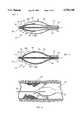
- FIG. 2is an isometric view of the surgical dilator tool with expandable incisors of the present invention shown in a retracted configuration
- FIG. 4is cross-sectional view of the surgical dilator tool with expandable incisors of the present invention taken along the line marked 4--4 in FIG. 2;
- FIG. 5is cross-sectional view of the surgical dilator tool with expandable incisors of the present invention taken along the line marked 5--5 in FIG. 3;
- FIG. 6is a plan view of the present invention operationally positioned within a vessel of a patient.
- a device for incising and dilating a treatment area, e.g., a stenosis, within a vesselis shown and generally designated 10. More specifically, the device 10 is shown positioned in the artery of a patient 12. As will be appreciated by the skilled artisan, the device 10 is shown schematically positioned in the patient 12, and it is to be understood that use of the device 10 is not confined to only upper body arteries and vessels but, instead, can be used in arteries and vessels throughout the patient 12.
- the device 10 of the present inventionincludes a placement catheter 18 having a distal end 20 and a proximal end 22.
- the placement catheter 18is formed from a resilient and flexible material, such as a polyamide, allowing the placement catheter 18 to be maneuvered within the vascular system of the patient 12.
- a rigid dilator housing 24is attached to the distal end 20 of the placement catheter 18 and has a generally ellipsoidal shape. Functionally, the ellipsoidal shape allows the dilator housing 24 to dilate a stenosis as the dilator housing 24 is either advanced or withdrawn through a stenosis.
- the device 10includes a cylindrical projection 25 that is attached to the distal end of the dilator housing 24 to pre-dilate the stenosis as the dilator housing 24 is advanced.
- the pre-dilation of the stenosisallows the blades 28 to contact the stenotic wall.
- the dilator housing 24 and projection 25can be formed from a single piece of a hard, rigid, plastic such as ABS.
- a basal strip 40is attached to the inner edge of each blade 28 giving the blade 28 an inverted T-shaped cross-section.
- the basal strip 40 of each blade 28is attached to the surface of the inflatable balloon 34 using a suitable adhesive.
- each blade 28moves with the balloon 34 as the balloon 34 is selectively inflated.
- each blade 28may be moved between the first configuration, shown in FIGS. 2 and 4, and the second configuration shown in FIGS. 3 and 5 by inflation or deflation of the balloon 34.
- each slit 26provides a guide, directing the movement of the corresponding blade 28.
- Each slit 26is also dimensioned to prevent passage of the basal strip 40.
- the placement guide catheter 18is formed with a guidewire lumen 42.
- the guidewire lumen 42extends throughout the placement catheter 18 and terminates at the distal end of the dilation housing 24.
- the guidewire lumen 42is dimensioned to receive a guidewire 44.
- operation of the device 10 of the present inventionbegins by prepositioning the guidewire 44 in the vessel 46 of patient 12. In this fashion, guidewire 44 establishes a pathway to and through the stenotic segment 48 which is to be dilated.
- the device 10is then inserted over the guidewire 44 by passing the guidewire 44 through the guidewire lumen 42 of the device 10.
- the device 10is then advanced over the guidewire 44 to position the dilation housing 24 at the site of the stenotic segment 48.
- the device 10is preferably configured in the first configuration (shown in FIGS. 2 and 4). In this configuration the balloon 34 is deflated and the blades 28 are withdrawn into the chamber 30. In this manner, inadvertent contact between the blades 28 and the vessel 46 is prevented.
- an inflator 16may be used to activate the fluid supply 18 to pass fluid under pressure through the inflation lumen 32 to inflate the balloon 34.
- the inflation of the balloon 34causes the device 10 to adopt the second configuration with the blades 28 extended radially from the dilator housing 24 through the slits 26. Consequently, any further movement of device 10 along guidewire 44 will cause the blades 28 to incise the stenosis 48. This incision is accompanied by a dilatation of the stenosis 48 caused by the simultaneous advancement of the dilation housing 24.
- device 10can be manipulated back and forth in the distal and proximal directions through the stenosis 48 as desired.
- incision and dilatation of the stenotic segment 48can be as aggressive as is required.
- a rapid to and fro reciprocating action combined with slight pressurecan be used to assist the cutting action of the blades.
- the inflator 16may be manipulated to pass fluid into balloon 34 to selectively increase or decrease the extension of the blades 28.
- the extension of the blades 28 from housing 24can be varied to configure device 10 as an incisor/dilator having different incising capabilities.
- the device 10can operate as a dilator or alternately, as an incisor, the device is capable of treating the entire length of the major coronary arteries and the major branches.
Landscapes
- Health & Medical Sciences (AREA)
- Surgery (AREA)
- Life Sciences & Earth Sciences (AREA)
- Biomedical Technology (AREA)
- Nuclear Medicine, Radiotherapy & Molecular Imaging (AREA)
- Engineering & Computer Science (AREA)
- Vascular Medicine (AREA)
- Heart & Thoracic Surgery (AREA)
- Medical Informatics (AREA)
- Molecular Biology (AREA)
- Animal Behavior & Ethology (AREA)
- General Health & Medical Sciences (AREA)
- Public Health (AREA)
- Veterinary Medicine (AREA)
- Media Introduction/Drainage Providing Device (AREA)
Abstract
Description
Claims (20)
Priority Applications (1)
| Application Number | Priority Date | Filing Date | Title |
|---|---|---|---|
| US08/743,716US5792158A (en) | 1995-11-15 | 1996-11-06 | University dilator with expandable incisor |
Applications Claiming Priority (2)
| Application Number | Priority Date | Filing Date | Title |
|---|---|---|---|
| US08/559,415US5697944A (en) | 1995-11-15 | 1995-11-15 | Universal dilator with expandable incisor |
| US08/743,716US5792158A (en) | 1995-11-15 | 1996-11-06 | University dilator with expandable incisor |
Related Parent Applications (1)
| Application Number | Title | Priority Date | Filing Date |
|---|---|---|---|
| US08/559,415Continuation-In-PartUS5697944A (en) | 1995-11-15 | 1995-11-15 | Universal dilator with expandable incisor |
Publications (1)
| Publication Number | Publication Date |
|---|---|
| US5792158Atrue US5792158A (en) | 1998-08-11 |
Family
ID=46252319
Family Applications (1)
| Application Number | Title | Priority Date | Filing Date |
|---|---|---|---|
| US08/743,716Expired - LifetimeUS5792158A (en) | 1995-11-15 | 1996-11-06 | University dilator with expandable incisor |
Country Status (1)
| Country | Link |
|---|---|
| US (1) | US5792158A (en) |
Cited By (92)
| Publication number | Priority date | Publication date | Assignee | Title |
|---|---|---|---|---|
| US6096054A (en)* | 1998-03-05 | 2000-08-01 | Scimed Life Systems, Inc. | Expandable atherectomy burr and method of ablating an occlusion from a patient's blood vessel |
| US6358244B1 (en) | 1996-07-12 | 2002-03-19 | Endo Surgical Devices, Inc. | Endarterectomy surgical instrument and procedure |
| EP1254679A3 (en)* | 2001-05-01 | 2003-01-02 | Interventional Technologies Inc | Folding spring for a catheter balloon |
| US20030144677A1 (en)* | 2002-01-25 | 2003-07-31 | Lary Banning Gray | Reciprocating cutting and dilating balloon |
| US20030163148A1 (en)* | 2002-02-27 | 2003-08-28 | Lixiao Wang | Medical device |
| US6632231B2 (en)* | 2001-08-23 | 2003-10-14 | Scimed Life Systems, Inc. | Segmented balloon catheter blade |
| US20030195536A1 (en)* | 2001-04-10 | 2003-10-16 | Mehran Bashiri | Devices and methods for removing occlusions in vessels |
| US20040073251A1 (en)* | 2002-10-15 | 2004-04-15 | Jan Weber | Nanotube paper-based medical device |
| US20040073284A1 (en)* | 2002-07-12 | 2004-04-15 | Cook Incorporated | Coated medical device |
| WO2004028610A3 (en)* | 2002-09-20 | 2004-06-03 | Bavaria Med Tech | Medical device for dispensing medicaments |
| US6746463B1 (en) | 2003-01-27 | 2004-06-08 | Scimed Life Systems, Inc | Device for percutaneous cutting and dilating a stenosis of the aortic valve |
| US20040133223A1 (en)* | 2003-01-02 | 2004-07-08 | Jan Weber | Medical devices |
| US20040189412A1 (en)* | 2003-03-25 | 2004-09-30 | Murata Manufacturing Co., Ltd. | Temperature compensated piezoelectric oscillator and electronic device using the same |
| US20040215223A1 (en)* | 2003-04-25 | 2004-10-28 | Shaw William J. | Cutting stent and balloon |
| US20040243156A1 (en)* | 2003-05-29 | 2004-12-02 | Scimed Life Systems, Inc. | Cutting balloon catheter with improved balloon configuration |
| US20040255447A1 (en)* | 2001-07-26 | 2004-12-23 | Kendall Mark Anthony Fernance | Particle cassette, method and kit therefor |
| US20050070888A1 (en)* | 2004-10-29 | 2005-03-31 | Boston Scientific Corporation | Medical device systems and methods |
| US20050119678A1 (en)* | 2003-12-01 | 2005-06-02 | O'brien Dennis | Cutting balloon having sheathed incising elements |
| US20050137617A1 (en)* | 2003-12-19 | 2005-06-23 | Kelley Gregory S. | Elastically distensible folding member |
| US20050137615A1 (en)* | 2003-12-19 | 2005-06-23 | Mapes Kenneth W. | Textured balloons |
| US20050137616A1 (en)* | 2003-12-19 | 2005-06-23 | Vigil Dennis M. | Balloon blade sheath |
| US20050137618A1 (en)* | 2003-12-19 | 2005-06-23 | Kunis Christopher G. | Balloon refolding device |
| US20050149102A1 (en)* | 2003-12-22 | 2005-07-07 | Radisch Herbert R.Jr. | Medical device systems |
| US20050149082A1 (en)* | 2003-12-31 | 2005-07-07 | Carl Yee | Microsurgical balloon with protective reinforcement |
| US20050245864A1 (en)* | 2004-04-30 | 2005-11-03 | O'brien Dennis | Directional cutting balloon |
| US20050261721A1 (en)* | 2004-05-24 | 2005-11-24 | Radisch Herbert R Jr | Medical device systems |
| US20050288629A1 (en)* | 2004-06-23 | 2005-12-29 | Christopher Kunis | Cutting balloon and process |
| US20060111736A1 (en)* | 2004-11-23 | 2006-05-25 | Kelley Greg S | Serpentine cutting blade for cutting balloon |
| US20060116701A1 (en)* | 2004-11-29 | 2006-06-01 | Crow Loren M | Balloon catheter with controlled depth incising blade |
| US20060116700A1 (en)* | 2004-11-29 | 2006-06-01 | Crow Loren M | Aortic stenosis cutting balloon blade |
| US20060129093A1 (en)* | 2004-12-03 | 2006-06-15 | Scimed Life Systems, Inc. | Multiple balloon catheter |
| US20060135980A1 (en)* | 2004-12-20 | 2006-06-22 | Scimed Life Systems, Inc. | Balloon with stepped sections and implements |
| US20060149308A1 (en)* | 2004-12-30 | 2006-07-06 | Cook Incorporated | Catheter assembly with plaque cutting balloon |
| US20060173487A1 (en)* | 2005-01-05 | 2006-08-03 | Cook Incorporated | Angioplasty cutting device and method for treating a stenotic lesion in a body vessel |
| US20060178685A1 (en)* | 2004-12-30 | 2006-08-10 | Cook Incorporated | Balloon expandable plaque cutting device |
| US20060182873A1 (en)* | 2005-02-17 | 2006-08-17 | Klisch Leo M | Medical devices |
| US20060247674A1 (en)* | 2005-04-29 | 2006-11-02 | Roman Ricardo D | String cutting balloon |
| US20070106215A1 (en)* | 2005-11-01 | 2007-05-10 | Cook Incorporated | Angioplasty cutting device and method for treating a stenotic lesion in a body vessel |
| US7291158B2 (en) | 2004-11-12 | 2007-11-06 | Boston Scientific Scimed, Inc. | Cutting balloon catheter having a segmented blade |
| US20080167608A1 (en)* | 2005-09-21 | 2008-07-10 | Rutter Michael John | Balloon dilator |
| US20080177294A1 (en)* | 2006-10-16 | 2008-07-24 | Depuy Spine, Inc. | Expandable intervertebral tool system and method |
| US20080200944A1 (en)* | 2007-02-13 | 2008-08-21 | Cook Incorporated | Balloon catheter with dilating elements |
| US20080228139A1 (en)* | 2007-02-06 | 2008-09-18 | Cook Incorporated | Angioplasty Balloon With Concealed Wires |
| US20080300610A1 (en)* | 2007-05-31 | 2008-12-04 | Cook Incorporated | Device for treating hardened lesions and method of use thereof |
| US20090171283A1 (en)* | 2007-12-27 | 2009-07-02 | Cook Incorporated | Method of bonding a dilation element to a surface of an angioplasty balloon |
| US20090171284A1 (en)* | 2007-12-27 | 2009-07-02 | Cook Incorporated | Dilation system |
| US7566319B2 (en) | 2004-04-21 | 2009-07-28 | Boston Scientific Scimed, Inc. | Traction balloon |
| US7632288B2 (en) | 2003-05-12 | 2009-12-15 | Boston Scientific Scimed, Inc. | Cutting balloon catheter with improved pushability |
| US20100010521A1 (en)* | 2008-07-10 | 2010-01-14 | Cook Incorporated | Cutting balloon with movable member |
| US7708753B2 (en) | 2005-09-27 | 2010-05-04 | Cook Incorporated | Balloon catheter with extendable dilation wire |
| WO2010017537A3 (en)* | 2008-08-08 | 2010-06-03 | Incept, Llc | Apparatus and methods for accessing and removing material from body lumens |
| US7750041B2 (en) | 2001-03-26 | 2010-07-06 | Bayer Schering Pharma Aktiengesellschaft | Preparation for the prophylaxis of restenosis |
| US7754047B2 (en) | 2004-04-08 | 2010-07-13 | Boston Scientific Scimed, Inc. | Cutting balloon catheter and method for blade mounting |
| US20100286593A1 (en)* | 2009-05-11 | 2010-11-11 | Hotspur Technologies, Inc. | Balloon catheter with cutting features and methods for use |
| US20100286721A1 (en)* | 2003-01-09 | 2010-11-11 | Boston Scientific Scimed, Inc. | Dilatation Catheter with Enhanced Distal End for Crossing Occluded Lesions |
| US20110152905A1 (en)* | 2009-12-22 | 2011-06-23 | Cook Incorporated | Balloon with scoring member |
| US7993358B2 (en) | 2005-02-11 | 2011-08-09 | Boston Scientific Scimed, Inc. | Cutting balloon catheter having increased flexibility regions |
| US8038691B2 (en) | 2004-11-12 | 2011-10-18 | Boston Scientific Scimed, Inc. | Cutting balloon catheter having flexible atherotomes |
| GB2485769A (en)* | 2010-11-22 | 2012-05-30 | Cook Medical Technologies Llc | Scoring balloon with tapered height scoring elements |
| US8192675B2 (en) | 2008-03-13 | 2012-06-05 | Cook Medical Technologies Llc | Cutting balloon with connector and dilation element |
| US20120203175A1 (en)* | 2010-07-09 | 2012-08-09 | Yifeng Sun | Ostomy system |
| US20120283624A1 (en)* | 2011-05-05 | 2012-11-08 | Gary Bradford Shirley | Drug Eluting Device and Method of Use Thereof |
| US8469943B2 (en) | 1995-06-07 | 2013-06-25 | Cook Medical Technologies Llc | Coated implantable medical device |
| US20130267959A1 (en)* | 2001-06-14 | 2013-10-10 | Alexandria Research Technologies, Inc. | Modular apparatus and method for sculpting the surface of a joint |
| US20140324079A1 (en)* | 2013-04-25 | 2014-10-30 | Invatec S.P.A. | Angioplasty balloon having selectively deployable cutting or scoring element and related methods |
| US20160199091A1 (en)* | 2015-01-13 | 2016-07-14 | John P. Pigott | Intravascular catheter balloon device having a tool for atherectomy or an incising portion for atheromatous plaque scoring |
| USRE46581E1 (en)* | 2001-04-17 | 2017-10-24 | Boston Scientific Scimed, Inc. | Cutting balloon catheter |
| US9956384B2 (en) | 2014-01-24 | 2018-05-01 | Cook Medical Technologies Llc | Articulating balloon catheter and method for using the same |
| US10182841B1 (en)* | 2015-06-16 | 2019-01-22 | C.R. Bard, Inc. | Medical balloon with enhanced focused force control |
| US10286190B2 (en) | 2013-12-11 | 2019-05-14 | Cook Medical Technologies Llc | Balloon catheter with dynamic vessel engaging member |
| US10335189B2 (en) | 2014-12-03 | 2019-07-02 | PAVmed Inc. | Systems and methods for percutaneous division of fibrous structures |
| WO2019203831A1 (en)* | 2018-04-19 | 2019-10-24 | C.R. Bard, Inc. | Catheter for active slicing /scoring and related methods |
| US10456160B2 (en) | 2015-03-09 | 2019-10-29 | Teleflex Innovations S.À.R.L. | Stenotic region scoring assembly and method |
| US10463387B2 (en) | 2011-09-13 | 2019-11-05 | John P. Pigott | Intravascular catheter having an expandable incising portion for incising atherosclerotic material located in a blood vessel |
| US10485570B2 (en) | 2011-09-13 | 2019-11-26 | John P. Pigott | Intravascular catheter having a cantilevered expandable incising portion |
| US10610255B2 (en) | 2011-09-13 | 2020-04-07 | John P. Pigott | Intravascular catheter having an expandable incising portion and medication delivery system |
| JP2020518345A (en)* | 2017-04-28 | 2020-06-25 | ダブリュ.エル.ゴア アンド アソシエイツ,インコーポレイティドW.L. Gore & Associates, Incorporated | Endoscopic transluminal stent access and delivery system |
| US10828471B2 (en) | 2013-07-15 | 2020-11-10 | John P. Pigott | Balloon catheter having a retractable sheath |
| US20210113820A1 (en)* | 2018-07-09 | 2021-04-22 | Goodman Co., Ltd. | Balloon catheter |
| US11033712B2 (en) | 2015-01-13 | 2021-06-15 | Venturemed Group, Inc. | Intravascular catheter having an expandable portion |
| US11154693B2 (en) | 2013-07-15 | 2021-10-26 | John P. Pigott | Balloon catheter having a retractable sheath |
| US11154694B2 (en) | 2013-07-15 | 2021-10-26 | John P. Pigott | Balloon catheter having a retractable sheath and locking mechanism with balloon recapture element |
| US20210378701A1 (en)* | 2019-02-28 | 2021-12-09 | C.R. Bard, Inc. | Active cutting catheter with housed expandable actuator |
| US11202892B2 (en) | 2013-07-15 | 2021-12-21 | John P. Pigott | Balloon catheter having a retractable sheath |
| US11357533B2 (en) | 2011-09-13 | 2022-06-14 | Venturemed Group, Inc. | Intravascular catheter having an expandable incising portion and abrasive surfaces |
| JPWO2022137763A1 (en)* | 2020-12-24 | 2022-06-30 | ||
| US11413062B2 (en) | 2011-09-13 | 2022-08-16 | Venturemed Group, Inc. | Methods for preparing a zone of attention within a vascular system for subsequent angioplasty with an intravascular catheter device having an expandable incising portion and an integrated embolic protection device |
| US11559325B2 (en) | 2011-09-13 | 2023-01-24 | Venturemed Group, Inc. | Intravascular catheter having an expandable incising portion and grating tool |
| US12096955B2 (en) | 2017-02-24 | 2024-09-24 | Venturemed Group, Inc. | Intravascular catheter having an expandable incising portion and abrasive surfaces |
| US12156693B2 (en) | 2020-05-27 | 2024-12-03 | PAVmed Inc. | Systems and methods for minimally-invasive division of fibrous structures |
| US12324603B2 (en) | 2011-09-13 | 2025-06-10 | Venturemed Group, Inc. | Intravascular catheter having an expandable incising portion |
| US12408932B2 (en) | 2022-03-23 | 2025-09-09 | Venturemed Group, Inc. | Intravascular device having feedback elements |
Citations (13)
| Publication number | Priority date | Publication date | Assignee | Title |
|---|---|---|---|---|
| US3635223A (en)* | 1969-12-02 | 1972-01-18 | Us Catheter & Instr Corp | Embolectomy catheter |
| US3990453A (en)* | 1973-04-25 | 1976-11-09 | Douvas Nicholas G | Apparatus for cataract surgery |
| US4273128A (en)* | 1980-01-14 | 1981-06-16 | Lary Banning G | Coronary cutting and dilating instrument |
| SU938977A1 (en)* | 1980-03-12 | 1982-06-30 | Предприятие П/Я А-3903 | Device for dissection of vessels walls |
| US4465072A (en)* | 1983-02-22 | 1984-08-14 | Taheri Syde A | Needle catheter |
| US4685458A (en)* | 1984-03-01 | 1987-08-11 | Vaser, Inc. | Angioplasty catheter and method for use thereof |
| US4696667A (en)* | 1986-03-20 | 1987-09-29 | Helmut Masch | Intravascular catheter and method |
| US4723549A (en)* | 1986-09-18 | 1988-02-09 | Wholey Mark H | Method and apparatus for dilating blood vessels |
| US5009659A (en)* | 1989-10-30 | 1991-04-23 | Schneider (Usa) Inc. | Fiber tip atherectomy catheter |
| US5100425A (en)* | 1989-09-14 | 1992-03-31 | Medintec R&D Limited Partnership | Expandable transluminal atherectomy catheter system and method for the treatment of arterial stenoses |
| US5156610A (en)* | 1989-08-18 | 1992-10-20 | Evi Corporation | Catheter atherotome |
| US5196024A (en)* | 1990-07-03 | 1993-03-23 | Cedars-Sinai Medical Center | Balloon catheter with cutting edge |
| US5320634A (en)* | 1990-07-03 | 1994-06-14 | Interventional Technologies, Inc. | Balloon catheter with seated cutting edges |
- 1996
- 1996-11-06USUS08/743,716patent/US5792158A/ennot_activeExpired - Lifetime
Patent Citations (13)
| Publication number | Priority date | Publication date | Assignee | Title |
|---|---|---|---|---|
| US3635223A (en)* | 1969-12-02 | 1972-01-18 | Us Catheter & Instr Corp | Embolectomy catheter |
| US3990453A (en)* | 1973-04-25 | 1976-11-09 | Douvas Nicholas G | Apparatus for cataract surgery |
| US4273128A (en)* | 1980-01-14 | 1981-06-16 | Lary Banning G | Coronary cutting and dilating instrument |
| SU938977A1 (en)* | 1980-03-12 | 1982-06-30 | Предприятие П/Я А-3903 | Device for dissection of vessels walls |
| US4465072A (en)* | 1983-02-22 | 1984-08-14 | Taheri Syde A | Needle catheter |
| US4685458A (en)* | 1984-03-01 | 1987-08-11 | Vaser, Inc. | Angioplasty catheter and method for use thereof |
| US4696667A (en)* | 1986-03-20 | 1987-09-29 | Helmut Masch | Intravascular catheter and method |
| US4723549A (en)* | 1986-09-18 | 1988-02-09 | Wholey Mark H | Method and apparatus for dilating blood vessels |
| US5156610A (en)* | 1989-08-18 | 1992-10-20 | Evi Corporation | Catheter atherotome |
| US5100425A (en)* | 1989-09-14 | 1992-03-31 | Medintec R&D Limited Partnership | Expandable transluminal atherectomy catheter system and method for the treatment of arterial stenoses |
| US5009659A (en)* | 1989-10-30 | 1991-04-23 | Schneider (Usa) Inc. | Fiber tip atherectomy catheter |
| US5196024A (en)* | 1990-07-03 | 1993-03-23 | Cedars-Sinai Medical Center | Balloon catheter with cutting edge |
| US5320634A (en)* | 1990-07-03 | 1994-06-14 | Interventional Technologies, Inc. | Balloon catheter with seated cutting edges |
Cited By (183)
| Publication number | Priority date | Publication date | Assignee | Title |
|---|---|---|---|---|
| US8469943B2 (en) | 1995-06-07 | 2013-06-25 | Cook Medical Technologies Llc | Coated implantable medical device |
| US6358244B1 (en) | 1996-07-12 | 2002-03-19 | Endo Surgical Devices, Inc. | Endarterectomy surgical instrument and procedure |
| US6416526B1 (en) | 1998-03-05 | 2002-07-09 | Scimed Life Systems, Inc. | Expandable atherectomy burr |
| US6096054A (en)* | 1998-03-05 | 2000-08-01 | Scimed Life Systems, Inc. | Expandable atherectomy burr and method of ablating an occlusion from a patient's blood vessel |
| US8389043B2 (en) | 2001-03-26 | 2013-03-05 | Bayer Pharma Aktiengesellschaft | Preparation for restenosis prevention |
| US7750041B2 (en) | 2001-03-26 | 2010-07-06 | Bayer Schering Pharma Aktiengesellschaft | Preparation for the prophylaxis of restenosis |
| US9066990B2 (en) | 2001-03-26 | 2015-06-30 | Bayer Intellectual Property Gmbh | Preparation for restenosis prevention |
| US20030195536A1 (en)* | 2001-04-10 | 2003-10-16 | Mehran Bashiri | Devices and methods for removing occlusions in vessels |
| USRE46581E1 (en)* | 2001-04-17 | 2017-10-24 | Boston Scientific Scimed, Inc. | Cutting balloon catheter |
| EP1254679A3 (en)* | 2001-05-01 | 2003-01-02 | Interventional Technologies Inc | Folding spring for a catheter balloon |
| US20130267959A1 (en)* | 2001-06-14 | 2013-10-10 | Alexandria Research Technologies, Inc. | Modular apparatus and method for sculpting the surface of a joint |
| US20040255447A1 (en)* | 2001-07-26 | 2004-12-23 | Kendall Mark Anthony Fernance | Particle cassette, method and kit therefor |
| US6632231B2 (en)* | 2001-08-23 | 2003-10-14 | Scimed Life Systems, Inc. | Segmented balloon catheter blade |
| US6951566B2 (en) | 2002-01-25 | 2005-10-04 | Scimed Life Systems, Inc. | Reciprocating cutting and dilating balloon |
| US20030144677A1 (en)* | 2002-01-25 | 2003-07-31 | Lary Banning Gray | Reciprocating cutting and dilating balloon |
| US7985234B2 (en) | 2002-02-27 | 2011-07-26 | Boston Scientific Scimed, Inc. | Medical device |
| US20030163148A1 (en)* | 2002-02-27 | 2003-08-28 | Lixiao Wang | Medical device |
| US20040073284A1 (en)* | 2002-07-12 | 2004-04-15 | Cook Incorporated | Coated medical device |
| US7803149B2 (en) | 2002-07-12 | 2010-09-28 | Cook Incorporated | Coated medical device |
| JP2005538814A (en)* | 2002-09-20 | 2005-12-22 | ババリア・メデイツイーン・テヒノロギー・ゲー・エム・ベー・ハー | Medical device for administering pharmaceuticals |
| WO2004028610A3 (en)* | 2002-09-20 | 2004-06-03 | Bavaria Med Tech | Medical device for dispensing medicaments |
| US9649476B2 (en) | 2002-09-20 | 2017-05-16 | Bayer Intellectual Property Gmbh | Medical device for dispersing medicaments |
| US20100228228A1 (en)* | 2002-09-20 | 2010-09-09 | Ulrich Speck | Medical device for dispersing medicaments |
| US8257305B2 (en) | 2002-09-20 | 2012-09-04 | Bayer Pharma Aktiengesellschaft | Medical device for dispensing medicaments |
| US8439868B2 (en) | 2002-09-20 | 2013-05-14 | Bayer Pharma AG | Medical device for dispersing medicaments |
| US20040073251A1 (en)* | 2002-10-15 | 2004-04-15 | Jan Weber | Nanotube paper-based medical device |
| US7493160B2 (en) | 2002-10-15 | 2009-02-17 | Boston Scientific Scimed, Inc. | Nano-actuated medical device |
| US20040138733A1 (en)* | 2002-10-15 | 2004-07-15 | Scimed Life Systems, Inc. | Nano-actuated medical device |
| US7037319B2 (en) | 2002-10-15 | 2006-05-02 | Scimed Life Systems, Inc. | Nanotube paper-based medical device |
| US7494497B2 (en)* | 2003-01-02 | 2009-02-24 | Boston Scientific Scimed, Inc. | Medical devices |
| US20040133223A1 (en)* | 2003-01-02 | 2004-07-08 | Jan Weber | Medical devices |
| US20100286721A1 (en)* | 2003-01-09 | 2010-11-11 | Boston Scientific Scimed, Inc. | Dilatation Catheter with Enhanced Distal End for Crossing Occluded Lesions |
| US6746463B1 (en) | 2003-01-27 | 2004-06-08 | Scimed Life Systems, Inc | Device for percutaneous cutting and dilating a stenosis of the aortic valve |
| US7029483B2 (en) | 2003-01-27 | 2006-04-18 | Scimed Life Systems, Inc. | Device for percutaneous cutting and dilating a stenosis of the aortic valve |
| US20040199191A1 (en)* | 2003-01-27 | 2004-10-07 | Leonard Schwartz | Device for percutaneous cutting and dilating a stenosis of the aortic valve |
| US20040189412A1 (en)* | 2003-03-25 | 2004-09-30 | Murata Manufacturing Co., Ltd. | Temperature compensated piezoelectric oscillator and electronic device using the same |
| US20040215223A1 (en)* | 2003-04-25 | 2004-10-28 | Shaw William J. | Cutting stent and balloon |
| US7279002B2 (en) | 2003-04-25 | 2007-10-09 | Boston Scientific Scimed, Inc. | Cutting stent and balloon |
| US8172864B2 (en) | 2003-05-12 | 2012-05-08 | Boston Scientific Scimed, Inc. | Balloon catheter with improved pushability |
| US8617193B2 (en) | 2003-05-12 | 2013-12-31 | Boston Scientific Scimed, Inc. | Balloon catheter with improved pushability |
| US7632288B2 (en) | 2003-05-12 | 2009-12-15 | Boston Scientific Scimed, Inc. | Cutting balloon catheter with improved pushability |
| US20040243156A1 (en)* | 2003-05-29 | 2004-12-02 | Scimed Life Systems, Inc. | Cutting balloon catheter with improved balloon configuration |
| US7758604B2 (en) | 2003-05-29 | 2010-07-20 | Boston Scientific Scimed, Inc. | Cutting balloon catheter with improved balloon configuration |
| US20050119678A1 (en)* | 2003-12-01 | 2005-06-02 | O'brien Dennis | Cutting balloon having sheathed incising elements |
| US20100312264A1 (en)* | 2003-12-01 | 2010-12-09 | Boston Scientific Scimed, Inc. | Cutting balloon having sheathed incising elements |
| US7799043B2 (en) | 2003-12-01 | 2010-09-21 | Boston Scientific Scimed, Inc. | Cutting balloon having sheathed incising elements |
| US20050137616A1 (en)* | 2003-12-19 | 2005-06-23 | Vigil Dennis M. | Balloon blade sheath |
| US8048093B2 (en) | 2003-12-19 | 2011-11-01 | Boston Scientific Scimed, Inc. | Textured balloons |
| US7338463B2 (en)* | 2003-12-19 | 2008-03-04 | Boston Scientific Scimed, Inc. | Balloon blade sheath |
| US7771447B2 (en) | 2003-12-19 | 2010-08-10 | Boston Scientific Scimed, Inc. | Balloon refolding device |
| US7413558B2 (en) | 2003-12-19 | 2008-08-19 | Boston Scientific Scimed, Inc. | Elastically distensible folding member |
| US20050137618A1 (en)* | 2003-12-19 | 2005-06-23 | Kunis Christopher G. | Balloon refolding device |
| US20050137615A1 (en)* | 2003-12-19 | 2005-06-23 | Mapes Kenneth W. | Textured balloons |
| US20050137617A1 (en)* | 2003-12-19 | 2005-06-23 | Kelley Gregory S. | Elastically distensible folding member |
| US20050149102A1 (en)* | 2003-12-22 | 2005-07-07 | Radisch Herbert R.Jr. | Medical device systems |
| US8043311B2 (en) | 2003-12-22 | 2011-10-25 | Boston Scientific Scimed, Inc. | Medical device systems |
| US20050149082A1 (en)* | 2003-12-31 | 2005-07-07 | Carl Yee | Microsurgical balloon with protective reinforcement |
| US7270673B2 (en) | 2003-12-31 | 2007-09-18 | Boston Scientific Scimed, Inc. | Microsurgical balloon with protective reinforcement |
| US7754047B2 (en) | 2004-04-08 | 2010-07-13 | Boston Scientific Scimed, Inc. | Cutting balloon catheter and method for blade mounting |
| US7566319B2 (en) | 2004-04-21 | 2009-07-28 | Boston Scientific Scimed, Inc. | Traction balloon |
| US8945047B2 (en) | 2004-04-21 | 2015-02-03 | Boston Scientific Scimed, Inc. | Traction balloon |
| US7070576B2 (en) | 2004-04-30 | 2006-07-04 | Boston Scientific Scimed, Inc. | Directional cutting balloon |
| US20050245864A1 (en)* | 2004-04-30 | 2005-11-03 | O'brien Dennis | Directional cutting balloon |
| US20050261721A1 (en)* | 2004-05-24 | 2005-11-24 | Radisch Herbert R Jr | Medical device systems |
| US8043259B2 (en) | 2004-05-24 | 2011-10-25 | Boston Scientific Scimed, Inc. | Medical device systems |
| US20050288629A1 (en)* | 2004-06-23 | 2005-12-29 | Christopher Kunis | Cutting balloon and process |
| US8986248B2 (en) | 2004-06-23 | 2015-03-24 | Boston Scientific Scimed, Inc. | Cutting balloon and process |
| US20110230818A1 (en)* | 2004-06-23 | 2011-09-22 | Boston Scientific Scimed, Inc. | Cutting balloon and process |
| US7976557B2 (en) | 2004-06-23 | 2011-07-12 | Boston Scientific Scimed, Inc. | Cutting balloon and process |
| US7753907B2 (en) | 2004-10-29 | 2010-07-13 | Boston Scientific Scimed, Inc. | Medical device systems and methods |
| US20050070888A1 (en)* | 2004-10-29 | 2005-03-31 | Boston Scientific Corporation | Medical device systems and methods |
| US8038691B2 (en) | 2004-11-12 | 2011-10-18 | Boston Scientific Scimed, Inc. | Cutting balloon catheter having flexible atherotomes |
| US8361096B2 (en) | 2004-11-12 | 2013-01-29 | Boston Scientific Scimed, Inc. | Cutting balloon catheter having flexible atherotomes |
| US9017353B2 (en) | 2004-11-12 | 2015-04-28 | Boston Scientific Scimed, Inc. | Cutting balloon catheter having flexible atherotomes |
| US9603619B2 (en) | 2004-11-12 | 2017-03-28 | Boston Scientific Scimed, Inc. | Cutting balloon catheter having flexible atherotomes |
| US8690903B2 (en) | 2004-11-12 | 2014-04-08 | Boston Scientific Scimed, Inc. | Cutting balloon catheter having flexible atherotomes |
| US7291158B2 (en) | 2004-11-12 | 2007-11-06 | Boston Scientific Scimed, Inc. | Cutting balloon catheter having a segmented blade |
| US20060111736A1 (en)* | 2004-11-23 | 2006-05-25 | Kelley Greg S | Serpentine cutting blade for cutting balloon |
| US8066726B2 (en) | 2004-11-23 | 2011-11-29 | Boston Scientific Scimed, Inc. | Serpentine cutting blade for cutting balloon |
| US7736375B2 (en) | 2004-11-29 | 2010-06-15 | Boston Scientific Scimed, Inc. | Balloon catheter with controller depth incising blade |
| US20060116701A1 (en)* | 2004-11-29 | 2006-06-01 | Crow Loren M | Balloon catheter with controlled depth incising blade |
| US20060116700A1 (en)* | 2004-11-29 | 2006-06-01 | Crow Loren M | Aortic stenosis cutting balloon blade |
| US7658744B2 (en) | 2004-12-03 | 2010-02-09 | Boston Scientific Scimed, Inc. | Multiple balloon catheter |
| US20060129093A1 (en)* | 2004-12-03 | 2006-06-15 | Scimed Life Systems, Inc. | Multiple balloon catheter |
| US20060135980A1 (en)* | 2004-12-20 | 2006-06-22 | Scimed Life Systems, Inc. | Balloon with stepped sections and implements |
| US7879053B2 (en) | 2004-12-20 | 2011-02-01 | Boston Scientific Scimed, Inc. | Balloon with stepped sections and implements |
| US20060149308A1 (en)* | 2004-12-30 | 2006-07-06 | Cook Incorporated | Catheter assembly with plaque cutting balloon |
| US20060178685A1 (en)* | 2004-12-30 | 2006-08-10 | Cook Incorporated | Balloon expandable plaque cutting device |
| US7303572B2 (en) | 2004-12-30 | 2007-12-04 | Cook Incorporated | Catheter assembly with plaque cutting balloon |
| US20060173487A1 (en)* | 2005-01-05 | 2006-08-03 | Cook Incorporated | Angioplasty cutting device and method for treating a stenotic lesion in a body vessel |
| US7993358B2 (en) | 2005-02-11 | 2011-08-09 | Boston Scientific Scimed, Inc. | Cutting balloon catheter having increased flexibility regions |
| US20060182873A1 (en)* | 2005-02-17 | 2006-08-17 | Klisch Leo M | Medical devices |
| US20060247674A1 (en)* | 2005-04-29 | 2006-11-02 | Roman Ricardo D | String cutting balloon |
| US20080167608A1 (en)* | 2005-09-21 | 2008-07-10 | Rutter Michael John | Balloon dilator |
| US7771446B2 (en) | 2005-09-21 | 2010-08-10 | Rutter Michael John | Balloon dilator |
| US7708753B2 (en) | 2005-09-27 | 2010-05-04 | Cook Incorporated | Balloon catheter with extendable dilation wire |
| US8123770B2 (en) | 2005-11-01 | 2012-02-28 | Cook Medical Technologies Llc | Angioplasty cutting device and method for treating a stenotic lesion in a body vessel |
| US20070106215A1 (en)* | 2005-11-01 | 2007-05-10 | Cook Incorporated | Angioplasty cutting device and method for treating a stenotic lesion in a body vessel |
| US9282980B2 (en) | 2006-10-16 | 2016-03-15 | DePuy Synthes Products, Inc. | Device and method for manipulating intervertebral tissue |
| US8137352B2 (en)* | 2006-10-16 | 2012-03-20 | Depuy Spine, Inc. | Expandable intervertebral tool system and method |
| US8882771B2 (en) | 2006-10-16 | 2014-11-11 | DePuy Synthes Products, LLC | Method for manipulating intervertebral tissue |
| US20080177294A1 (en)* | 2006-10-16 | 2008-07-24 | Depuy Spine, Inc. | Expandable intervertebral tool system and method |
| US9211394B2 (en) | 2007-02-06 | 2015-12-15 | Cook Medical Technologies Llc | Angioplasty balloon with conceal wires |
| US20080228139A1 (en)* | 2007-02-06 | 2008-09-18 | Cook Incorporated | Angioplasty Balloon With Concealed Wires |
| US9192747B2 (en) | 2007-02-13 | 2015-11-24 | Cook Medical Technologies Llc | Balloon catheter with dilating elements |
| US8323307B2 (en) | 2007-02-13 | 2012-12-04 | Cook Medical Technologies Llc | Balloon catheter with dilating elements |
| US20080200944A1 (en)* | 2007-02-13 | 2008-08-21 | Cook Incorporated | Balloon catheter with dilating elements |
| US8906049B2 (en) | 2007-05-31 | 2014-12-09 | Cook Medical Technologies Llc | Device for treating hardened lesions and method of use thereof |
| US9119944B2 (en) | 2007-05-31 | 2015-09-01 | Cook Medical Technologies Llc | Device for treating hardened lesions and method of use thereof |
| US8870816B2 (en) | 2007-05-31 | 2014-10-28 | Cook Medical Technologies Llc | Device for treating hardened lesions |
| US20080300610A1 (en)* | 2007-05-31 | 2008-12-04 | Cook Incorporated | Device for treating hardened lesions and method of use thereof |
| US20090171284A1 (en)* | 2007-12-27 | 2009-07-02 | Cook Incorporated | Dilation system |
| US20090171283A1 (en)* | 2007-12-27 | 2009-07-02 | Cook Incorporated | Method of bonding a dilation element to a surface of an angioplasty balloon |
| US10016212B2 (en) | 2008-03-13 | 2018-07-10 | Cook Medical Technologies Llc | Cutting balloon with connector and dilation element |
| US8192675B2 (en) | 2008-03-13 | 2012-06-05 | Cook Medical Technologies Llc | Cutting balloon with connector and dilation element |
| US10617443B2 (en) | 2008-03-13 | 2020-04-14 | Cook Medical Technologies Llc | Cutting balloon with connector and dilation element |
| US9604036B2 (en) | 2008-03-13 | 2017-03-28 | Cook Medical Technologies Llc | Cutting balloon with connector and dilation element |
| WO2009117563A3 (en)* | 2008-03-21 | 2009-11-19 | Michael John Rutter | Balloon dilator |
| US20100010521A1 (en)* | 2008-07-10 | 2010-01-14 | Cook Incorporated | Cutting balloon with movable member |
| US10849647B2 (en) | 2008-08-08 | 2020-12-01 | Incept, Inc. | Apparatus and methods for accessing and removing material from body lumens |
| US9126015B2 (en) | 2008-08-08 | 2015-09-08 | Incept, Llc | Apparatus and methods for accessing and removing material from body lumens |
| WO2010017537A3 (en)* | 2008-08-08 | 2010-06-03 | Incept, Llc | Apparatus and methods for accessing and removing material from body lumens |
| US10085765B2 (en) | 2008-08-08 | 2018-10-02 | Incept, Inc. | Apparatus and methods for accessing and removing material from body lumens |
| US20100286593A1 (en)* | 2009-05-11 | 2010-11-11 | Hotspur Technologies, Inc. | Balloon catheter with cutting features and methods for use |
| US8348987B2 (en) | 2009-12-22 | 2013-01-08 | Cook Medical Technologies Llc | Balloon with scoring member |
| US20110152905A1 (en)* | 2009-12-22 | 2011-06-23 | Cook Incorporated | Balloon with scoring member |
| US20120203175A1 (en)* | 2010-07-09 | 2012-08-09 | Yifeng Sun | Ostomy system |
| GB2485769B (en)* | 2010-11-22 | 2012-12-05 | Cook Medical Technologies Llc | Scoring balloon and method of making same |
| GB2485769A (en)* | 2010-11-22 | 2012-05-30 | Cook Medical Technologies Llc | Scoring balloon with tapered height scoring elements |
| US20120283624A1 (en)* | 2011-05-05 | 2012-11-08 | Gary Bradford Shirley | Drug Eluting Device and Method of Use Thereof |
| US10485570B2 (en) | 2011-09-13 | 2019-11-26 | John P. Pigott | Intravascular catheter having a cantilevered expandable incising portion |
| US10610255B2 (en) | 2011-09-13 | 2020-04-07 | John P. Pigott | Intravascular catheter having an expandable incising portion and medication delivery system |
| US12324603B2 (en) | 2011-09-13 | 2025-06-10 | Venturemed Group, Inc. | Intravascular catheter having an expandable incising portion |
| US11123097B2 (en) | 2011-09-13 | 2021-09-21 | Venturemed Group, Inc. | Intravascular catheter having an expandable incising portion |
| US12185968B2 (en) | 2011-09-13 | 2025-01-07 | Venturemed Group, Inc. | Intravascular catheter having an expandable incising portion |
| US11576698B2 (en) | 2011-09-13 | 2023-02-14 | Venturemed Group, Inc. | Intravascular catheter device for improved angioplasty |
| US11571239B2 (en) | 2011-09-13 | 2023-02-07 | Venturemed Group, Inc. | Intravascular catheter having an expandable incising portion and medication delivery system |
| US10463387B2 (en) | 2011-09-13 | 2019-11-05 | John P. Pigott | Intravascular catheter having an expandable incising portion for incising atherosclerotic material located in a blood vessel |
| US10939936B2 (en) | 2011-09-13 | 2021-03-09 | Venturemed Group, Inc. | Intravascular catheter with incising devices |
| US10485572B2 (en) | 2011-09-13 | 2019-11-26 | John P. Pigott | Intravascular catheter having an expandable incising portion |
| US11559325B2 (en) | 2011-09-13 | 2023-01-24 | Venturemed Group, Inc. | Intravascular catheter having an expandable incising portion and grating tool |
| US11331118B2 (en) | 2011-09-13 | 2022-05-17 | Venturemed Group, Inc. | Intravascular catheter having an expandable incising portion |
| US11413062B2 (en) | 2011-09-13 | 2022-08-16 | Venturemed Group, Inc. | Methods for preparing a zone of attention within a vascular system for subsequent angioplasty with an intravascular catheter device having an expandable incising portion and an integrated embolic protection device |
| US11357533B2 (en) | 2011-09-13 | 2022-06-14 | Venturemed Group, Inc. | Intravascular catheter having an expandable incising portion and abrasive surfaces |
| US20140324079A1 (en)* | 2013-04-25 | 2014-10-30 | Invatec S.P.A. | Angioplasty balloon having selectively deployable cutting or scoring element and related methods |
| US9808276B2 (en)* | 2013-04-25 | 2017-11-07 | Invatec S.P.A. | Angioplasty balloon having selectively deployable cutting or scoring element and related methods |
| US10828471B2 (en) | 2013-07-15 | 2020-11-10 | John P. Pigott | Balloon catheter having a retractable sheath |
| US11154693B2 (en) | 2013-07-15 | 2021-10-26 | John P. Pigott | Balloon catheter having a retractable sheath |
| US11202892B2 (en) | 2013-07-15 | 2021-12-21 | John P. Pigott | Balloon catheter having a retractable sheath |
| US11154694B2 (en) | 2013-07-15 | 2021-10-26 | John P. Pigott | Balloon catheter having a retractable sheath and locking mechanism with balloon recapture element |
| US10286190B2 (en) | 2013-12-11 | 2019-05-14 | Cook Medical Technologies Llc | Balloon catheter with dynamic vessel engaging member |
| US9956384B2 (en) | 2014-01-24 | 2018-05-01 | Cook Medical Technologies Llc | Articulating balloon catheter and method for using the same |
| US11259837B2 (en) | 2014-12-03 | 2022-03-01 | PAVmed Inc. | Systems and methods for percutaneous division of fibrous structures |
| US10335189B2 (en) | 2014-12-03 | 2019-07-02 | PAVmed Inc. | Systems and methods for percutaneous division of fibrous structures |
| US12114888B2 (en) | 2014-12-03 | 2024-10-15 | PAVmed Inc. | Systems and methods for percutaneous division of fibrous structures |
| US11141186B2 (en) | 2014-12-03 | 2021-10-12 | PAVmed Inc. | Systems and methods for percutaneous division of fibrous structures |
| US10603069B2 (en)* | 2015-01-13 | 2020-03-31 | John P. Pigott | Intravascular catheter balloon device having a tool for atherectomy or an incising portion for atheromatous plaque scoring |
| US11033712B2 (en) | 2015-01-13 | 2021-06-15 | Venturemed Group, Inc. | Intravascular catheter having an expandable portion |
| US11850376B2 (en) | 2015-01-13 | 2023-12-26 | Venturemed Group, Inc. | Intravascular catheter having an expandable portion |
| US20160199091A1 (en)* | 2015-01-13 | 2016-07-14 | John P. Pigott | Intravascular catheter balloon device having a tool for atherectomy or an incising portion for atheromatous plaque scoring |
| US10456160B2 (en) | 2015-03-09 | 2019-10-29 | Teleflex Innovations S.À.R.L. | Stenotic region scoring assembly and method |
| US10182841B1 (en)* | 2015-06-16 | 2019-01-22 | C.R. Bard, Inc. | Medical balloon with enhanced focused force control |
| US11202651B2 (en)* | 2015-06-16 | 2021-12-21 | C.R. Bard, Inc. | Medical balloon with enhanced focused force control |
| US12408942B2 (en) | 2016-07-01 | 2025-09-09 | Venturemed Group, Inc. | Intravascular catheter having an expandable incising portion and embolic protection device |
| US12096955B2 (en) | 2017-02-24 | 2024-09-24 | Venturemed Group, Inc. | Intravascular catheter having an expandable incising portion and abrasive surfaces |
| JP2020518345A (en)* | 2017-04-28 | 2020-06-25 | ダブリュ.エル.ゴア アンド アソシエイツ,インコーポレイティドW.L. Gore & Associates, Incorporated | Endoscopic transluminal stent access and delivery system |
| US11589884B2 (en) | 2017-04-28 | 2023-02-28 | W. L. Gore & Associates, Inc. | Endoscopic transluminal stent access and delivery system |
| US11918247B2 (en) | 2018-04-19 | 2024-03-05 | C.R. Bard, Inc. | Catheter for active slicing/scoring and related methods |
| JP2021526039A (en)* | 2018-04-19 | 2021-09-30 | シー・アール・バード・インコーポレーテッドC R Bard Incorporated | Catheter and related methods for active slicing / scoring |
| WO2019203831A1 (en)* | 2018-04-19 | 2019-10-24 | C.R. Bard, Inc. | Catheter for active slicing /scoring and related methods |
| JP2022126755A (en)* | 2018-04-19 | 2022-08-30 | シー・アール・バード・インコーポレーテッド | Catheter for active slicing/scoring, and related methods |
| CN112020336A (en)* | 2018-04-19 | 2020-12-01 | 巴德股份有限公司 | Catheter and related methods for active sectioning/scratching |
| US20210113820A1 (en)* | 2018-07-09 | 2021-04-22 | Goodman Co., Ltd. | Balloon catheter |
| US12042613B2 (en)* | 2018-07-09 | 2024-07-23 | Goodman Co., Ltd. | Balloon catheter |
| US11896258B2 (en)* | 2019-02-28 | 2024-02-13 | C.R. Bard, Inc. | Active cutting catheter with housed expandable actuator |
| JP2022529405A (en)* | 2019-02-28 | 2022-06-22 | シー・アール・バード・インコーポレーテッド | Active cutting catheter with contained expandable actuator |
| US20210378701A1 (en)* | 2019-02-28 | 2021-12-09 | C.R. Bard, Inc. | Active cutting catheter with housed expandable actuator |
| US12156693B2 (en) | 2020-05-27 | 2024-12-03 | PAVmed Inc. | Systems and methods for minimally-invasive division of fibrous structures |
| JPWO2022137763A1 (en)* | 2020-12-24 | 2022-06-30 | ||
| CN116635105A (en)* | 2020-12-24 | 2023-08-22 | 株式会社钟化 | Balloon Catheter Balloon |
| WO2022137763A1 (en)* | 2020-12-24 | 2022-06-30 | 株式会社カネカ | Balloon for balloon catheter |
| US12433633B2 (en) | 2021-04-02 | 2025-10-07 | Venturemed Group, Inc. | Intravascular catheter having an expandable incising portion |
| US12408932B2 (en) | 2022-03-23 | 2025-09-09 | Venturemed Group, Inc. | Intravascular device having feedback elements |
Similar Documents
| Publication | Publication Date | Title |
|---|---|---|
| US5792158A (en) | University dilator with expandable incisor | |
| US5697944A (en) | Universal dilator with expandable incisor | |
| EP0829238B1 (en) | Incisor-dilator with tapered balloon | |
| US7172609B2 (en) | Apparatus for supporting a segmented blade on a balloon catheter | |
| US6951566B2 (en) | Reciprocating cutting and dilating balloon | |
| CA2157697C (en) | Vascular incisor/dilator | |
| EP0565796B1 (en) | Stenosis dilatation device | |
| US7413558B2 (en) | Elastically distensible folding member | |
| US6306151B1 (en) | Balloon with reciprocating stent incisor | |
| US5797935A (en) | Balloon activated forced concentrators for incising stenotic segments | |
| US5713913A (en) | Device and method for transecting a coronary artery | |
| EP1587431B1 (en) | A device for percutaneous cutting and dilating a stenosis of the aortic valve | |
| US5556405A (en) | Universal dilator with reciprocal incisor | |
| US7597703B2 (en) | Mechanically expandable occluder | |
| US5624433A (en) | Angioplasty balloon with light incisor |
Legal Events
| Date | Code | Title | Description |
|---|---|---|---|
| AS | Assignment | Owner name:INTERVENTIONAL TECHNOLOGIES INC., CALIFORNIA Free format text:ASSIGNMENT OF ASSIGNORS INTEREST;ASSIGNOR:LARY, BANNING GRAY;REEL/FRAME:008327/0730 Effective date:19961104 | |
| STCF | Information on status: patent grant | Free format text:PATENTED CASE | |
| CC | Certificate of correction | ||
| FEPP | Fee payment procedure | Free format text:PAT HOLDER NO LONGER CLAIMS SMALL ENTITY STATUS, ENTITY STATUS SET TO UNDISCOUNTED (ORIGINAL EVENT CODE: STOL); ENTITY STATUS OF PATENT OWNER: LARGE ENTITY | |
| REFU | Refund | Free format text:REFUND - PAYMENT OF MAINTENANCE FEE, 4TH YR, SMALL ENTITY (ORIGINAL EVENT CODE: R283); ENTITY STATUS OF PATENT OWNER: LARGE ENTITY | |
| FPAY | Fee payment | Year of fee payment:4 | |
| SULP | Surcharge for late payment | ||
| FPAY | Fee payment | Year of fee payment:8 | |
| AS | Assignment | Owner name:BOSTON SCIENTIFIC SCIMED, INC., MINNESOTA Free format text:REQUEST FOR CORRECTION OF NON-RECORDATION OF ASSIGNMENT DOCUMENT.;ASSIGNOR:SCIMED LIFE SYSTEMS, INC.;REEL/FRAME:018563/0192 Effective date:20050101 | |
| AS | Assignment | Owner name:SCIMED LIFE SYSTEMS, INC., MINNESOTA Free format text:ASSIGNMENT OF ASSIGNORS INTEREST;ASSIGNOR:INTERVENTIONAL TECHNOLOGIES INC.;REEL/FRAME:018767/0269 Effective date:20020101 | |
| FPAY | Fee payment | Year of fee payment:12 | |
| AS | Assignment | Owner name:LARY, BANNING G., FLORIDA Free format text:ASSIGNMENT OF ASSIGNORS INTEREST;ASSIGNOR:BOSTON SCIENTIFIC SCIMED, INC.;REEL/FRAME:038250/0179 Effective date:20121120 |