US5792069A - Method and system for the extraction of cardiac artifacts from EEG signals - Google Patents
Method and system for the extraction of cardiac artifacts from EEG signalsDownload PDFInfo
- Publication number
- US5792069A US5792069AUS08/773,100US77310096AUS5792069AUS 5792069 AUS5792069 AUS 5792069AUS 77310096 AUS77310096 AUS 77310096AUS 5792069 AUS5792069 AUS 5792069A
- Authority
- US
- United States
- Prior art keywords
- artifact
- input signal
- signal
- filter
- interval
- Prior art date
- Legal status (The legal status is an assumption and is not a legal conclusion. Google has not performed a legal analysis and makes no representation as to the accuracy of the status listed.)
- Expired - Lifetime
Links
- 230000000747cardiac effectEffects0.000titleclaimsabstractdescription20
- 238000000034methodMethods0.000titleclaimsdescription24
- 238000000605extractionMethods0.000title1
- 230000002490cerebral effectEffects0.000claimsabstractdescription13
- 102100026827Protein associated with UVRAG as autophagy enhancerHuman genes0.000claimsdescription56
- 101710102978Protein associated with UVRAG as autophagy enhancerProteins0.000claimsdescription56
- 230000004044responseEffects0.000claimsdescription13
- 238000001514detection methodMethods0.000claimsdescription6
- 230000002123temporal effectEffects0.000claimsdescription4
- 238000009499grossingMethods0.000claims2
- 239000003623enhancerSubstances0.000description30
- 230000008569processEffects0.000description13
- 230000007704transitionEffects0.000description10
- 238000010586diagramMethods0.000description9
- 230000003595spectral effectEffects0.000description8
- 238000005314correlation functionMethods0.000description7
- 230000006870functionEffects0.000description5
- 238000001914filtrationMethods0.000description3
- 241001123248ArmaSpecies0.000description2
- 230000002411adverseEffects0.000description2
- 230000003444anaesthetic effectEffects0.000description2
- 238000005070samplingMethods0.000description2
- 230000009471actionEffects0.000description1
- 230000003925brain functionEffects0.000description1
- 230000007423decreaseEffects0.000description1
- 230000036541healthEffects0.000description1
- 238000012986modificationMethods0.000description1
- 230000004048modificationEffects0.000description1
- 210000004165myocardiumAnatomy0.000description1
- 238000000718qrs complexMethods0.000description1
- 230000001373regressive effectEffects0.000description1
- 230000030074regulation of atrial cardiomyocyte membrane repolarizationEffects0.000description1
- 230000000241respiratory effectEffects0.000description1
- 230000033764rhythmic processEffects0.000description1
- 230000000630rising effectEffects0.000description1
- 230000001629suppressionEffects0.000description1
- 238000001356surgical procedureMethods0.000description1
Images


Classifications
- A—HUMAN NECESSITIES
- A61—MEDICAL OR VETERINARY SCIENCE; HYGIENE
- A61B—DIAGNOSIS; SURGERY; IDENTIFICATION
- A61B5/00—Measuring for diagnostic purposes; Identification of persons
- A61B5/72—Signal processing specially adapted for physiological signals or for diagnostic purposes
- A61B5/7203—Signal processing specially adapted for physiological signals or for diagnostic purposes for noise prevention, reduction or removal
- A61B5/7217—Signal processing specially adapted for physiological signals or for diagnostic purposes for noise prevention, reduction or removal of noise originating from a therapeutic or surgical apparatus, e.g. from a pacemaker
- A—HUMAN NECESSITIES
- A61—MEDICAL OR VETERINARY SCIENCE; HYGIENE
- A61B—DIAGNOSIS; SURGERY; IDENTIFICATION
- A61B5/00—Measuring for diagnostic purposes; Identification of persons
- A61B5/24—Detecting, measuring or recording bioelectric or biomagnetic signals of the body or parts thereof
- A61B5/316—Modalities, i.e. specific diagnostic methods
- A61B5/369—Electroencephalography [EEG]
Definitions
- the present inventionrelates to an improved filter for filtering signals representative of cerebral activity. More particularly, the present invention relates to a filter for removing cardiac or other artifacts from EEG signals.
- EEGelectroencephalographic
- U.S. Pat. No. 5,458,117entitled CEREBRAL BIOPOTENTIAL ANALYSIS SYSTEM AND METHOD, issued to Chamoun et al. on Oct. 17, 1996, which is assigned to the assignee of the present invention, describes a system and method for generating a bispectral index from EEG signals.
- the bispectral index discussed in that patentis a single time varying number that is generally indicative of a patient's anesthetic state. This bispectral index may be used to effectively monitor the anesthetic state of a patient during a surgical procedure.
- EEG signalsfrequently include artifacts generated as a result of a cardiac QRS complex, or operation of a pacemaker.
- the presence of such artifactscan adversely affect the operation of any device used to process the EEG signals. It is therefore an object of the present invention to provide a filter for removing such artifacts from EEG signals.
- the filterreceives an input signal representative of a patient's cerebral activity (e.g., an EEG signal) and generates therefrom an artifact free, or reduced artifact, filtered signal.
- the filterremoves artifacts from the input signal and replaces the removed portions (that included the artifact) with artifact free portions of the input signal temporally adjacent the removed portions.
- the filterreplaces the removed portions (that included the artifact) with portions of another input signal.
- FIG. 1shows a block diagram of a ECG and pacer artifact filter constructed according to the invention
- FIG. 2shows a block diagram of a preferred embodiment of the ECG and pacer artifact filter shown in FIG. 1;
- FIGS. 3A-Fshow graphs of amplitude versus time of signals that illustrate the operation of the filter shown in FIG. 2;
- FIG. 4shows a block diagram of a preferred embodiment of the outlier enhancer shown in FIG. 2;
- FIGS. 5A-Eshow graphs of amplitude versus time of signals that illustrate the operation of the filter shown in FIG. 2;
- FIG. 6shows a flow chart illustrating the process used by the spike remover shown in FIG. 2 to remove ECG and pacer artifacts from the EEG signal;
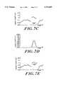
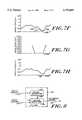
- FIGS. 7 A-Hshow graphs of amplitude versus time of signals that illustrate the operation of mover shown in FIG. 2;
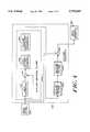
- FIG. 8shows a block diagram of another embodiment of a filter constructed according to the invention.
- FIG. 1shows a block diagram of a filter 120 constructed according to the invention.
- Filter 120receives an input signal 110 representative of cerebral activity of a patient (not shown) and generates therefrom a filtered signal 112.
- the input signal 110may be, for example, an EEG signal generated in known fashion by one or more EEG electrodes, or alternatively, by an amplifier or other known EEG processing components.
- the filtered signal 112 generated by filter 120may be applied to any device used to process EEG signals (e.g., such as a bispectral index generator of the type disclosed in the above-referenced U.S. Pat. No. 5,458,117).
- the filtering provided by filter 120may improve the performance of any device used to process signals representative of cerebral activity.
- filter 120includes a spike detector 130 and a spike remover 140.
- the input signal 110is applied to spike detector 130 and spike remover 140.
- Spike detector 130generates an output signal 150 that is applied to spike remover 140.
- the lattergenerates the filtered signal 112 in response to the input signal 110 and the output signal 150.
- spike detector 130detects the presence of artifacts in input signal 110 and generates the output signal 150 so that it represents the temporal location of the artifacts in input signal 110.
- spike remover 140When the input signal 110 does not include an artifact (as indicated by the output signal 150), spike remover 140 generates the filtered signal 112 so that it is substantially equal to the input signal 110.
- spike remover 140when the input signal 110 includes an artifact (as indicated by the output signal 150), spike remover 140 generates the corresponding portion of the filtered signal 112 by setting that portion equal to an artifact free portion of the input signal 110 temporally adjacent the portion of the input signal 110 that included the artifact.
- filter 120is preferably implemented as a digital filter. Since most frequency components of interest in EEG signals are below sixty Hertz (Hz), sample rates of above 120 Hz satisfy the Nyquist criteria and a preferred sampling rate for use with filter 120 is 128 Hz. Most components of filter 120 preferably process their relevant signals in successive temporal segments referred to as epochs.
- An epoch of a single signalincludes a set of N data points x i for all integers i from one to N. Different components within filter 120 may use epochs of different lengths (e.g., one second or two second epochs). With the preferred sample rate of 128 Hz, each single second epoch of data includes 128 data points.
- filter 120is implemented as an ECG and pacer artifact filter.
- input signal 110is an EEG signal and filter 120 processes the EEG signal 110 to remove ECG and pacer artifacts from the filtered signal 112.
- ECG and pacer artifactsare cardiac artifacts in that they relate to the heart.
- ECG artifactsare artifacts that arise naturally from the action of the heart muscle (i.e., the electrocardiogram QRS complex).
- Pacer artifactsarise from electrical instruments used to control the rhythm of the heart (e.g., pacemakers).
- the conductivity of the bodyoften causes these cardiac artifacts to appear in measured EEG signals. Presence of these artifacts in the EEG signals may interfere with the operation of processing components such as a bispectral index generator, so filter 120 detects and removes these artifacts.
- filter 120preferably generates the filtered signal by (1) removing portions of the EEG signal 110 that include ECG or pacer artifacts, and by (2) replacing the removed portions of data with original (artifact free) data in portions of the EEG signal 110 temporally adjacent the removed portions. Replacing the removed portions of data in this fashion insures that the resulting filtered signal includes sufficient data for processing components such as a bispectral index generator to accurately process.
- FIG. 2shows a detailed block diagram of a preferred embodiment of the ECG and pacer artifact filter 120 constructed according to the invention.
- Filter 120includes two high pass filters 210, 212; two band pass filters 214, 216; an outlier enhancer 218; an ECG spike detector 220; a pacer spike detector 222; and a spike remover 224.
- the EEG signal 110is applied to high pass filters 210, 212, and to spike remover 224.
- High pass filters 210 and 212filter the EEG signal 110 and thereby generate output signals that are applied to band pass filters 214 and 216, respectively.
- Band pass filters 214 and 216filter the signals received from high pass filters 210 and 212, respectively, and apply the resulting signals to outlier enhancer 218 and pacer spike detector 222, respectively.
- Outlier enhancer 218receives the signal from band pass filter 214 and generates therefrom a signal that is applied to ECG spike detector 220.
- ECG spike detector 220 and pacer spike detector 222each generate an output signal and these signals are both applied to spike remover 224. The latter generates the filtered signal 112.
- high pass filter 210, band pass filter 214, outlier enhancer 218, and ECG spike detector 220cooperatively operate to locate ECG artifacts in the EEG signal 110.
- FIGS. 3A-3Eshow graphs of amplitude versus time of signals that illustrate the operation of filters 210, 214, outlier enhancer 218, and ECG spike detector 220.
- FIG. 3Ashows an example of an EEG signal 110 received by high pass filter 210 that includes regularly occurring ECG artifacts some of which are indicated at 310.
- High pass filter 210filters this EEG signal to remove low frequency EEG and artifact, such as baseline wander, which may arise, for example, from slowly varying electrode interface characteristics or respiratory cycle related movement.
- High pass filter 210is preferably characterized by a high pass cutoff frequency that is selected high enough to effectively remove baseline wander and low enough to pass the ECG artifacts.
- One preferred value for the high pass cutoff frequencyis 5 Hz.
- Filter 210may be implemented for example as a first order Auto Regressive first order Moving Average ARMA(1,1)! filter.
- filter 210is a digital filter characterized by a transfer function shown in the following Equation (1). ##EQU1##
- Equation (1)x i represents the current unfiltered sample of the EEG signal applied to the input of filter 210, and y i and y i-1 represent the current and previous samples of the output signal generated by filter 210.
- the filter coefficients a 1 , b 0 , and b 1are equal to 0.72338247, 1.0, and -1.0, respectively.
- FIG. 3Cshows a graph of an output signal generated by band pass filter 214 in response to the signal shown in FIG. 3B.
- Band pass filter 214is characterized by a pass band that is preferably selected so as to accentuate the "spiky" components of the ECG artifacts (as shown in FIG. 3C) and to thereby facilitate their subsequent detection.
- One preferred range for the pass band of filter 214is 18-42 Hz.
- band pass filter 214is implemented as a digital pseudo-matched finite impulse response (FIR) filter (i.e., piece-wise linear "complex”) filter and is characterized by a transfer function given by the following Equation (2). ##EQU2##
- FIRfinite impulse response
- the filter coefficients b 0 through b 8are selected as follows:
- FIG. 3Dshows a graph of an output signal generated by outlier enhancer 218 in response to the signal shown in FIG. 3C.
- outlier enhancer 218accentuates the ECG artifact and suppresses the rest of the signal.
- Outliers in the signal generated by band pass filter 214e.g., data points that deviate significantly from the mean value of the signal
- Outlier enhancer 218preferably increases the value of outlying data points and decreases the value of other data points to facilitate subsequent artifact detection.
- Outlier enhancer 218preferably uses outlier removal methods described below and in L. H. Larson and P. N. Prinz, "EKG Artifacts Suppression from the EEG", Electroenceph. Olin. Neurophys. 79 (1991) pp. 241-244.
- Outlier enhancer 218preferably processes the signal received from band pass filter 214 in single second epochs.
- the outlier enhancer 218processes the N data points x i in one epoch and then processes the N data points in the next epoch of data.
- outlier enhancer 218processes each epoch of data by first adjusting the data so that it has a mean of zero. To perform this zero mean adjustment, outlier enhancer 218 first generates the mean of the data in the epoch according to the following Equation (3). ##EQU3##
- Outlier enhancer 218then subtracts the mean from every data point in the epoch to generate a set of "zero mean data points" x i according to the following Equation (4).
- Outlier enhancer 218then generates the standard deviation (or the RMS power) of all the zero mean data points in the epoch according to the following Equation (5). ##EQU4##
- Outlier enhancer 218then generates data points x' i for a line that represents the "least squares fit" to the zero mean data points x i .
- the data points x' imay be generated according to the following Equation (6). ##EQU5##
- Equation (7)The function f(Z) is selected so that the operation of Equation (7) tends to set the value of the data points x out i to the predicted value x' i plus a scaled difference of the predicted and zero mean values. If however, the original data point x i was an outlier, the corresponding data points x out i is set equal to the predicted value x' i (see the equation above). Outlier enhancer 218 then generates its final output data points by subtracting the data points received from band pass filter 214 from the corresponding data points x out i .
- FIG. 4shows a block diagram of a preferred embodiment of outlier enhancer 218 that includes a cascade of three outlier removal filters 410a, 410b, and 410c, and a subtractor 420.
- the output signal generated by band pass filter 214is applied to filter 410a and to the positive input of subtractor 420.
- Filter 410areceives the signal from band pass filter 214 and generates therefrom an output signal that is applied to filter 410b, which in turn generates an output signal that is applied to filter 410c.
- the lattergenerates an output signal that is applied to a negative input of subtractor 420 which in turn generates the output signal of outlier enhancer 218 that is applied to ECG spike detector 220 (shown in FIG. 2).
- FIG. 2shows a block diagram of a preferred embodiment of outlier enhancer 218 that includes a cascade of three outlier removal filters 410a, 410b, and 410c, and a subtractor 420.
- Filter 410aincludes a mean generator 412, a subtractor 414, a least squares fit generator 416, and an outlier suppressed data point generator 418.
- mean generator 412generates the mean of all the data points in an epoch according to the above Equation (3) and applies the mean to a negative input of subtractor 414.
- Subtractor 414then generates the zero mean data points x i according to the above Equation (4) by subtracting the mean from the original data points and applies the zero mean data points to least squares fit line generator 416.
- Least squares fit line generator 416then generates the least squares fit line data points x' i according to the above Equation (6).
- Outlier suppressed data point generator 418then generates the outlier suppressed data points x out i according to the above Equations (5) and (7).
- Outlier filters 410b and 410cthen each repeat in succession the steps of zero mean generation, least squares line fitting, and outlier suppressed data point generation so that the data points generated by filter 410c significantly suppress the ECG artifacts.
- Subtractor 420then enhances the ECG artifacts by subtracting the data points generated by filter 410c from the data points generated by band pass filter 214.
- Other embodiments of outlier enhancer 218could of course include more than or less than three outlier removal filters.
- FIG. 3Eshows a graph of the output signal generated by ECG spike detector 220 in response to the signal received from outlier enhancer 218 and illustrated in FIG. 3D.
- the output signal generated by ECG spike detector 220which is applied to spike remover 224, indicates the location of ECG artifacts in the EEG signal 110.
- a low valueindicates the absence of an ECG artifact
- a high valueindicates the location of an ECG artifact.
- ECG artifactsare generally characterized by relatively large steep-sloped segments alternating (i.e., rising and falling) within a predetermined period.
- ECG artifact 312shown in FIG. 3D
- ECG artifact 312includes a steep negative transition from a value near zero to the negative data point 314, followed by a steep positive transition (across zero) to the positive data point 316, followed by a steep negative transition (across zero) to the negative data point 318, finally followed by a steep positive transition to a value near zero.
- ECG spike detector 220preferably detects the presence, and determines the locations, of ECG artifacts by identifying zero-crossings (i.e., locations where the signal transitions from a negative value "across zero” to a positive value, or transitions from a positive value "across zero” to a negative value).
- ECG spike detector 220generates an output signal indicative of the presence of an ECG artifact whenever the detector locates M zero-crossings in the signal generated by outlier enhancer 218 in a time interval of duration T 1 , where M is greater than or equal to two and less than or equal to four, and where T 1 is equal to approximately 200 ms.
- ECG spike detector 220uses a threshold ZCTR 1 to determine when zero crossings occur. That is, detector 220 will consider any transition from -ZCTR 1 to ZCTR 1 or from ZCTR 1 to -ZCTR 1 in the signal received from outlier enhancer 218 as a zero crossing.
- the threshold ZCTR 1Requiring the magnitude of the zero crossings to be greater than a threshold prevents zero crossings caused by small amounts of random noise from being considered as ECG artifacts.
- One preferred value for the threshold ZCTR 1is 8.032 ⁇ V, however, as those skilled in the art will appreciate, this threshold is preferably appropriately varied depending on the type of EEG electrodes used as well as other well known factors. In any particular implementation of filter 120, the threshold ZCTR 1 is preferably empirically selected so that it reliably distinguishes actual ECG artifacts from noise.
- the ECG spike detector 220also preferably uses other criteria to prevent detection of an ECG artifact even if M zero crossings greater than ZCTR 1 are present in an interval of duration T 1 . These additional criteria are selected to prevent noise from being detected as an ECG artifact. For example, if spike detector 220 detects five or more zero crossings greater than a second threshold ZCTR 2 (i.e., transitions from -ZCTR 2 to ZCTR 2 or from ZCTR 2 to -ZCTR 2 ) in the signal generated by outlier enhancer 218 in an interval of duration T 2 , then spike detector 220 will generate an output signal indicative of the absence of an ECG artifact.
- a second threshold ZCTR 2i.e., transitions from -ZCTR 2 to ZCTR 2 or from ZCTR 2 to -ZCTR 2
- the second threshold ZCTR 2is less than the first threshold ZCTR 1 , and one preferred value for the second threshold ZCTR 2 is approximately equal to 3.02727 ⁇ V.
- the second duration T 2is preferably longer than the first duration T 1 and one preferred value for the second duration is about half of a second.
- ECG spike detector 220also preferably generates an output signal indicative of the absence of an ECG artifact if there is one very large excursion (e.g., greater than 100 ⁇ V) of the signal generated by outlier enhancer 218 within an interval of about half of a second. This prevents electrosurgical noise from being detected as ECG artifacts.
- FIGS. 5A-5Dshow graphs of amplitude versus time of signals that illustrate the operation of filters 212, 216, and of pacer spike detector 222.
- FIG. 5Ashows an example of an EEG signal 110 received by high pass filter 212 that includes regularly occurring pacer artifacts some of which are indicated at 510.
- High pass filter 212preferably filters this EEG signal to remove low frequency baseline wander.
- High pass filter 212is preferably characterized by a high pass cutoff frequency that is selected high enough to effectively remove baseline wander and low enough to pass the pacer artifacts.
- One preferred value for the high pass cutoff frequency for filter 212is 20 Hz.
- Filter 212may be implemented as an ARMA(1,1) filter characterized by the transfer function shown in the above Equation (1), where the filter coefficients a l , b 0 , and b 1 , are given by -0.48672403, 1.0, and -1.0, respectively.
- Band pass filter 216is preferably selected to accentuate the spiky portions of the pacer artifacts.
- Band pass filter 216may be implemented using a filter that is identical to the above discussed band pass filter 214.
- FIG. 5Cshows the output signal generated by band pass filter 216 in response to the signal received from high pass filter 212 and illustrated in FIG. 5B.
- Pacer spike detector 222generates an output signal that illustrates the presence or absence of pacer artifacts in the EEG signal 110.
- FIG. 5Dshows the output signal generated by pacer spike detector 222 in response to the signal received from band pass filter 216 and illustrated in FIG. 5C. In the illustrated signal, high values indicate the location of pacer artifacts and low values illustrate the absence of pacer artifacts.
- Pacer spike detector 222preferably generates its output signal by cross-correlating the signal received from band pass filter 216 with predetermined templates. Whenever any of the cross-correlations exceeds a predetermined threshold, spike detector 222 generates an output signal indicative of the presence of a pacer artifact and at all other times spike detector 222 generates an output signal indicative of the absence of a pacer artifact.
- a set of three preferred templates for use with pacer spike detector 222is shown below.
- Pacer spike detector 222preferably generates cross-correlation functions for each of the three templates shown above according to a function of the "lag" or time shift between the template and the data in the epoch.
- the cross-correlation function ⁇ (r)is preferably generated according to the following Equation (8). ##EQU7##
- x irepresents data points in the signal received from band pass filter 216
- y irepresents data points in one of the three templates shown above
- Nis the number of data points in an epoch.
- Pacer spike detector 222When generated according to Equation (8), the magnitude of cross-correlation functions ⁇ (r) will have values that range between zero and one.
- Pacer spike detector 222preferably generates an output signal indicative of the location of a pacer artifact wherever the cross-correlation function ⁇ (r) for TEMPLATE1 is greater than a first threshold THR 1 and also preferably generates an output signal indicative of the location of a pacer artifact wherever the cross-correlation function ⁇ (r) for TEMPLATE2 or TEMPLATE3 is greater than a second threshold THR 2 .
- Preferred values for THR 1 and THR 2are 0.85 and 0.75, respectively, although those skilled in the art will appreciate that other values for the threshold and other templates could also be used.
- high pass filter 210, band pass filter 214, outlier enhancer 218, and ECG spike detector 220cooperatively operate to identify the location of ECG artifacts in the EEG signal 110
- high pass filter 212, band pass filter 216, and pacer spike detector 222cooperatively operate to identify the location of pacer artifacts in the EEG signal 110.
- These componentsi.e., high pass filters 210, 212, band pass filters 214, 216, outlier enhancer 218, ECG spike detector 220, and pacer spike detector 222
- Spike remover 224uses the signals generated by ECG spike detector 220 and pacer spike detector 222 to remove the ECG and pacer artifacts from the EEG signal 110. While high pass filters 210, 212, band bass filters 214, 216, outlier enhancer 218, and ECG and pacer spike detectors 220, 222 represent a preferred embodiment for detecting the presence and location of ECG and pacer artifacts, those skilled in the art will appreciate that spike remover 224 may be used with other filters that detect the presence of ECG and pacer artifacts or of other artifacts.
- pacer spike detector 222has been discussed in connection with templates and correlation functions, those skilled in the art will appreciate that spike detector 222 could also operate using zero crossing detection schemes similar to the one discussed above in connection with ECG spike detector 220 and tuned to detect pacer artifacts. Similarly, ECG spike detector 220 could operate using appropriate templates and correlation functions rather than by detecting zero crossings.
- EEG signal 110 and the signals generated by ECG spike detector 220 and pacer spike detector 222are received by spike remover 224.
- Spike remover 224generates the filtered signal so that it is equal to the EEG signal 110 when the output signals from spike detectors 220 and 222 indicate an absence of ECG and pacer artifacts.
- spike remover 224When spike detectors 220 and 222 indicate the presence of an ECG or a pacer artifact, spike remover 224 generates the filtered signal by replacing the portion of the EEG signal including the artifact with artifact free data in the EEG signal that is temporally adjacent to the portion including the artifact.
- Spike remover 224also preferably filters the signal so that the replaced portions fit smoothly into the original artifact free portions.
- FIG. 6shows a flow chart 600 that illustrates one preferred method that spike remover 224 may use to generate portions of the filtered signal corresponding to portions of the EEG signal 110, including ECG or pacer artifacts.
- spike remover 224determines a size SZ of a removal region of the EEG signal including the artifact.
- FIG. 7Ashows a portion of an EEG signal 700 that includes an ECG artifact 710.
- ECG spike detector 220or pacer spike detector 222 in the case of a pacer artifact informs spike remover 224 of the temporal location of the ECG artifact.
- Spike remover 224selects a replacement region 712 that is preferably centered about, and fully surrounds (i.e., extends before and after), the artifact 710.
- spike remover 224selects the size SZ of the replacement region 712 to be equal to thirteen samples when the artifact is an ECG artifact and selects the size SZ to be equal to seventeen samples when the artifact is a pacer artifact. These values of thirteen and seventeen samples correspond to the average length of ECG and pacer artifacts (101.6 msec and 132.8 msec, respectively) and a sampling rate of one hundred twenty eight samples per second.
- step 612spike remover 224 determines the parameters of a line (i.e., the slope m and the offset b) that connects the first and last data points in the removal region 712.
- FIG. 7Ashows the line 714 connecting the first and last data points in the removal region 712.
- the epoch of data points including the artifact 710includes data points x i for all integers i from one to N, and the artifact 710 is centered around a data point x p .
- Spike remover 224selects the removal region 712 so that it is centered around data point x p , and since the removal region includes SZ samples, the removal region extends from data points X p- (SZ-1)/2 to X p+ (SZ-1)/2.
- Spike remover 224may generate the slope m and offset b of line 714 according to the following Equation (9). ##EQU8##
- step 614spike remover 224 saves the first and last data points in the removal region 712 as x first and X last , respectively, and then copies all the data points from a region 716 that precedes and is temporally adjacent the replacement region 712 into the replacement region.
- FIG. 7Billustrates the results of copying the data points in region 716 into the replacement region 712.
- the data in the replacement region 712is typically not continuous with the data in the region 716 preceding the replacement region 712 and with the data in a region 718 following the removal region 712.
- Spike remover 224may execute step 614 according to the following Equation (10). ##EQU9##
- the data points x r irepresent the data points copied into the replacement region 712.
- spike remover 224replaces the data points x r i copied into replacement region 712 with zero mean data points x i as is illustrated in FIG. 7C.
- Spike remover 224may execute step 616 by generating the mean x r and by then subtracting the mean from every data point x r i to generate the zero mean data points x i according to the following Equation (11). ##EQU10##
- step 618spike remover 224 tapers the edges of the data points in the replacement region 712, preferably by multiplying the zero mean data points x i in the replacement region 712 by a Hanning spectral window, an example of a Hanning spectral window being illustrated in FIG. 7D.
- the Hanning spectral windowmay be defined by a set of data points w han j for all integers j from one to SZ, where the data points w han j are given by the following Equation (12). ##EQU11##
- Spike remover 224may multiply the Hanning spectral window by the zero mean data points to generate a set of tapered data points x taper i according to the following Equation (13), the tapered data points x taper i being illustrated in FIG. 7E. ##EQU12##
- step 620spike remover 224 linearly shifts the tapered data points x taper i in the replacement region 712 by an amount determined by the line segment 714 (shown in FIG. 7A) that was measured during step 612 and thereby generates a set of new data points x new i .
- the result of this linear shifting of the replacement region 712is shown in FIG. 7F.
- Spike remover 224may execute step 620 according to the following Equation (14) for all i from p-(SZ-1)/2 to p+(SZ-1)/2.
- the new data points x new i in the replacement region 712are continuous with the data in the regions 716 and 718 that immediately precede and follow, respectively, the replacement region. However, the transitions between regions 716 and 712 and between regions 712 and 718 are not smooth.
- step 622spike remover 224 tapers the data at the right end of region 716 and at the left end of region 718 so that the transitions between these regions and the removal region 712 become both smooth and continuous.
- the results of this tapering operationare shown in FIG. 7H.
- One way to accomplish this taperingis to multiply the data points in the right half of region 716 by the right half of a Hanning window, and to multiply the data points in the left half of region 718 by the left half of a Hanning window as shown in FIG. 7G.
- Spike remover 224may accomplish this tapering operation according to the following Equation (15). ##EQU13##
- ECG and pacer artifact filter 120removes data in regions of the EEG signal 110 that include ECG or pacer artifacts and replaces the data in those removed regions with data from a region temporally adjacent (and preferably preceding) the removed region.
- Filter 120also preferably tapers the data at the beginning and end of the removed regions and also tapers the data at the ends of the regions preceding removed regions and also tapers the data at the beginnings of regions following the removed regions so that the data in the removed regions connects smoothly with the data in regions preceding and following the removed regions.
- FIG. 3Fshows a filtered signal generated by filter 120 in response to the EEG signal shown in FIG. 3A.
- FIG. 5Eshows a filtered signal generated by filter 120 in response to the EEG signal shown in FIG. 5A.
- the pacer artifacts present in the signal shown in FIG. 5Ahave been smoothly removed from the signal shown in FIG. 5E.
- filter 120may operate in different fashions as well.
- the data which is copied into the replacement regionmay come from a second EEG signal which is artifact free.
- filter 120removes and tapers the data in ways that do not significantly alter the spectral content of the EEG signal.
- FIG. 8shows a block diagram of another embodiment of filter 120.
- filter 120receives two input signals 110a, 110b representative of cerebral activity and generates therefrom the filtered signal 112.
- the input signals 110a, 110bmay represent, for example, EEG signals from two different channels of an EEG processor.
- the first input signal 110ais applied to both the spike detector 130 and the spike remover 140, and the second input signal 110b is applied to only the spike remover 140.
- the filter 120In operation, when there are no artifacts present in the input signal 110a (as indicated by the output signal 150 of spike detector 130), the filter 120 generates the filtered signal 112 so that it is substantially equal to the first input signal 110a. When there is an artifact present in the first input signal 110a (as indicated by the output signal 150), the filter 120 generates the corresponding portion of the filtered signal using data from the second (preferably artifact free) input signal 110b.
- This embodimentmay be particularly useful for systems that normally monitor several different channels of EEG signals. Filter 120 may for example select the channel containing the lowest amount of artifacts to use as the source of the second input signal 110b.
- spike detector 130may be configured to detect cardiac artifacts such as ECG or pacer artifacts. Alternatively, spike detector 130 may be configured to detect any type of artifacts characterized by "spike" like shapes.
- digital embodiments of filter 120generate a digital filtered signal corresponding to a digital input signal.
- filter 120When the input signal does not include an artifact, filter 120 generates data points of the filtered signal so that they are substantially equal to corresponding data points of the input signal.
- filter 120When the input signal does include an artifact, filter 120 generates data points of the filtered signal so that they are substantially equal to data points from a portion of the input signal temporally adjacent the portion of the input signal including the artifact, or so that they are substantially equal to data points from another input signal.
- Filter 120of course also applied filtering as discussed above to smooth portions of the filtered signal corresponding to portions of the input signal that included an artifact so data in the replacement regions connects smoothly with adjacent portions of the signal.
- Filter 120has been discussed in terms of a digital implementation. Those skilled in the art will appreciate that various components of filter 120 (e.g., high pass filter 210 as shown in FIG. 2) may be implemented using discrete hardware modules, or alternatively, may be implemented using software executed by a digital computer. In other embodiments, some components of filter 120 (e.g., high pass filter 210) may be implemented using analog devices.
- filter 120has been discussed for convenience as being partitioned into separate modules (e.g., high pass filter 210 and band pass filter 214), however, those skilled in the art will appreciate that these divisions have been presented merely for convenience of exposition, and filter 120 may be partitioned in different ways without departing from the scope of the invention, and all of filter 120 may be implemented as a single module that is implemented, for example, as software executed by a digital computer.
Landscapes
- Health & Medical Sciences (AREA)
- Life Sciences & Earth Sciences (AREA)
- Engineering & Computer Science (AREA)
- Signal Processing (AREA)
- Heart & Thoracic Surgery (AREA)
- Medical Informatics (AREA)
- Psychiatry (AREA)
- Physics & Mathematics (AREA)
- Veterinary Medicine (AREA)
- Biophysics (AREA)
- Pathology (AREA)
- Biomedical Technology (AREA)
- Public Health (AREA)
- General Health & Medical Sciences (AREA)
- Molecular Biology (AREA)
- Surgery (AREA)
- Animal Behavior & Ethology (AREA)
- Physiology (AREA)
- Artificial Intelligence (AREA)
- Computer Vision & Pattern Recognition (AREA)
- Psychology (AREA)
- Measurement And Recording Of Electrical Phenomena And Electrical Characteristics Of The Living Body (AREA)
- Apparatus For Radiation Diagnosis (AREA)
- Selective Calling Equipment (AREA)
Abstract
Description
x.sub.i =x.sub.i -X (4)
x new.sub.i =x taper.sub.i +mi+b (14)
Claims (22)
Priority Applications (8)
| Application Number | Priority Date | Filing Date | Title |
|---|---|---|---|
| US08/773,100US5792069A (en) | 1996-12-24 | 1996-12-24 | Method and system for the extraction of cardiac artifacts from EEG signals |
| EP97952570AEP0957761B1 (en) | 1996-12-24 | 1997-12-19 | System for the extraction of cardiac artifacts from eeg signals |
| CA002275901ACA2275901C (en) | 1996-12-24 | 1997-12-19 | System for the extraction of cardiac artifacts from eeg signals |
| JP52900498AJP4025926B2 (en) | 1996-12-24 | 1997-12-19 | System for extracting heart-related artificial elements from EEG signals |
| DE69724286TDE69724286T2 (en) | 1996-12-24 | 1997-12-19 | DEVICE FOR SEPARATING CARDIAL INTERFERENCE SIGNALS FROM EEG SIGNALS |
| AT97952570TATE247419T1 (en) | 1996-12-24 | 1997-12-19 | DEVICE FOR SEPARATING CARDIAL INTERFERENCE SIGNALS FROM EEG SIGNALS |
| PCT/US1997/023624WO1998027864A1 (en) | 1996-12-24 | 1997-12-19 | System for the extraction of cardiac artifacts from eeg signals |
| AU56150/98AAU732539B2 (en) | 1996-12-24 | 1997-12-19 | System for the extraction of cardiac artifacts from EEG signals |
Applications Claiming Priority (1)
| Application Number | Priority Date | Filing Date | Title |
|---|---|---|---|
| US08/773,100US5792069A (en) | 1996-12-24 | 1996-12-24 | Method and system for the extraction of cardiac artifacts from EEG signals |
Publications (1)
| Publication Number | Publication Date |
|---|---|
| US5792069Atrue US5792069A (en) | 1998-08-11 |
Family
ID=25097209
Family Applications (1)
| Application Number | Title | Priority Date | Filing Date |
|---|---|---|---|
| US08/773,100Expired - LifetimeUS5792069A (en) | 1996-12-24 | 1996-12-24 | Method and system for the extraction of cardiac artifacts from EEG signals |
Country Status (8)
| Country | Link |
|---|---|
| US (1) | US5792069A (en) |
| EP (1) | EP0957761B1 (en) |
| JP (1) | JP4025926B2 (en) |
| AT (1) | ATE247419T1 (en) |
| AU (1) | AU732539B2 (en) |
| CA (1) | CA2275901C (en) |
| DE (1) | DE69724286T2 (en) |
| WO (1) | WO1998027864A1 (en) |
Cited By (53)
| Publication number | Priority date | Publication date | Assignee | Title |
|---|---|---|---|---|
| US6216031B1 (en)* | 1998-02-11 | 2001-04-10 | Marquette Hellige Gmbh | Apparatus for enhancing signals in ECGs artefacts |
| WO2001083007A2 (en) | 2000-05-03 | 2001-11-08 | Aspect Medical Systems, Inc. | System and method for adaptive drug delivery |
| US20020085174A1 (en)* | 2000-11-22 | 2002-07-04 | Ciaran Bolger | Method and apparatus for monitoring eye tremor |
| US20030009111A1 (en)* | 2001-06-13 | 2003-01-09 | Cory Philip C. | Non-invasive method and apparatus for tissue detection |
| US20030052775A1 (en)* | 2001-06-21 | 2003-03-20 | Aspect Medical Systems, Inc. | System and method for the detection and removal of radio frequency noise artifact from biopotential signals |
| US20030144600A1 (en)* | 2002-01-28 | 2003-07-31 | Nihon Kohden Corporation | Vital sign display monitor |
| US20050280531A1 (en)* | 2004-06-18 | 2005-12-22 | Fadem Kalford C | Device and method for transmitting physiologic data |
| US20060085048A1 (en)* | 2004-10-20 | 2006-04-20 | Nervonix, Inc. | Algorithms for an active electrode, bioimpedance-based tissue discrimination system |
| US20060085049A1 (en)* | 2004-10-20 | 2006-04-20 | Nervonix, Inc. | Active electrode, bio-impedance based, tissue discrimination system and methods of use |
| US20060167722A1 (en)* | 2004-01-27 | 2006-07-27 | Aspect Medical Systems, Inc. | System and method for adaptive drug delivery |
| US20070135728A1 (en)* | 2005-12-01 | 2007-06-14 | Lexicor Medical Technology, Llc | Systems and Methods for Analyzing and Assessing Depression and Other Mood Disorders Using Electroencephalographic (EEG) Measurements |
| US20080234596A1 (en)* | 2007-03-21 | 2008-09-25 | Hyun Wook Park | Brain Wave Measuring Method, Apparatus And Computer Readable Recording Medium Implemented With Program For Executing The Method |
| US20080249431A1 (en)* | 2006-09-29 | 2008-10-09 | The Regents Of The University Of California | Burst suppression monitor for induced coma |
| US20080273084A1 (en)* | 2003-11-07 | 2008-11-06 | Neuro Kinetics, Inc. | Integrated video and electro-oculography system |
| US20100092049A1 (en)* | 2008-04-08 | 2010-04-15 | Neuro Kinetics, Inc. | Method of Precision Eye-Tracking Through Use of Iris Edge Based Landmarks in Eye Geometry |
| US20100094161A1 (en)* | 2008-10-09 | 2010-04-15 | Neuro Kinetics, Inc. | Quantitative, non-invasive, clinical diagnosis of traumatic brain injury using simulated distance visual stimulus device for neurologic testing |
| US20100100037A1 (en)* | 2007-12-18 | 2010-04-22 | Hospira, Inc. | Touch screen system and navigation and programming methods for an infusion pump |
| US20100160998A1 (en)* | 2004-10-23 | 2010-06-24 | Bell John O | Passive monitoring of bioelectical signals and active electrical anesthesia stimulation |
| US20110066065A1 (en)* | 2009-08-28 | 2011-03-17 | Lexicor Medical Technology, Llc | Systems and methods to identify a subgroup of adhd at higher risk for complicating conditions |
| US20110157192A1 (en)* | 2009-12-29 | 2011-06-30 | Microsoft Corporation | Parallel Block Compression With a GPU |
| US20130030267A1 (en)* | 2011-07-29 | 2013-01-31 | Nellcor Puritan Bennett Llc | Multi-purpose sensor system |
| US20130165918A1 (en)* | 2011-12-27 | 2013-06-27 | Medtronic, Inc. | Electrosurgery detection |
| US9039631B2 (en) | 2008-10-09 | 2015-05-26 | Neuro Kinetics | Quantitative, non-invasive, clinical diagnosis of traumatic brain injury using VOG device for neurologic testing |
| US9538949B2 (en) | 2010-09-28 | 2017-01-10 | Masimo Corporation | Depth of consciousness monitor including oximeter |
| US10022498B2 (en) | 2011-12-16 | 2018-07-17 | Icu Medical, Inc. | System for monitoring and delivering medication to a patient and method of using the same to minimize the risks associated with automated therapy |
| US10154815B2 (en) | 2014-10-07 | 2018-12-18 | Masimo Corporation | Modular physiological sensors |
| US10166328B2 (en) | 2013-05-29 | 2019-01-01 | Icu Medical, Inc. | Infusion system which utilizes one or more sensors and additional information to make an air determination regarding the infusion system |
| US10342917B2 (en) | 2014-02-28 | 2019-07-09 | Icu Medical, Inc. | Infusion system and method which utilizes dual wavelength optical air-in-line detection |
| US10398309B2 (en) | 2008-10-09 | 2019-09-03 | Neuro Kinetics, Inc. | Noninvasive rapid screening of mild traumatic brain injury using combination of subject's objective oculomotor, vestibular and reaction time analytic variables |
| US10430761B2 (en) | 2011-08-19 | 2019-10-01 | Icu Medical, Inc. | Systems and methods for a graphical interface including a graphical representation of medical data |
| US10463788B2 (en) | 2012-07-31 | 2019-11-05 | Icu Medical, Inc. | Patient care system for critical medications |
| US10578474B2 (en) | 2012-03-30 | 2020-03-03 | Icu Medical, Inc. | Air detection system and method for detecting air in a pump of an infusion system |
| US10596316B2 (en) | 2013-05-29 | 2020-03-24 | Icu Medical, Inc. | Infusion system and method of use which prevents over-saturation of an analog-to-digital converter |
| US10635784B2 (en) | 2007-12-18 | 2020-04-28 | Icu Medical, Inc. | User interface improvements for medical devices |
| US10656894B2 (en) | 2017-12-27 | 2020-05-19 | Icu Medical, Inc. | Synchronized display of screen content on networked devices |
| US10743808B2 (en) | 2012-08-06 | 2020-08-18 | Neuro Kinetics | Method and associated apparatus for detecting minor traumatic brain injury |
| US10850024B2 (en) | 2015-03-02 | 2020-12-01 | Icu Medical, Inc. | Infusion system, device, and method having advanced infusion features |
| US10874793B2 (en) | 2013-05-24 | 2020-12-29 | Icu Medical, Inc. | Multi-sensor infusion system for detecting air or an occlusion in the infusion system |
| CN112932475A (en)* | 2021-02-01 | 2021-06-11 | 武汉泰利美信医疗科技有限公司 | Method and device for calculating blood oxygen saturation, electronic equipment and storage medium |
| US11135360B1 (en) | 2020-12-07 | 2021-10-05 | Icu Medical, Inc. | Concurrent infusion with common line auto flush |
| US11246985B2 (en) | 2016-05-13 | 2022-02-15 | Icu Medical, Inc. | Infusion pump system and method with common line auto flush |
| US11278671B2 (en) | 2019-12-04 | 2022-03-22 | Icu Medical, Inc. | Infusion pump with safety sequence keypad |
| US11324888B2 (en) | 2016-06-10 | 2022-05-10 | Icu Medical, Inc. | Acoustic flow sensor for continuous medication flow measurements and feedback control of infusion |
| US11344673B2 (en) | 2014-05-29 | 2022-05-31 | Icu Medical, Inc. | Infusion system and pump with configurable closed loop delivery rate catch-up |
| US11344668B2 (en) | 2014-12-19 | 2022-05-31 | Icu Medical, Inc. | Infusion system with concurrent TPN/insulin infusion |
| US20220167908A1 (en)* | 2019-03-18 | 2022-06-02 | Health Tech Connex Inc. | System and method for automatic evoked potential measurement |
| EP4096769A1 (en)* | 2020-01-30 | 2022-12-07 | Medtronic, Inc. | Disturbance detection and removal in cardiac signals |
| US11596340B2 (en) | 2017-03-31 | 2023-03-07 | Koninklijke Philips N.V. | Methods and system for processing an EMG signal |
| US11883361B2 (en) | 2020-07-21 | 2024-01-30 | Icu Medical, Inc. | Fluid transfer devices and methods of use |
| US11980469B2 (en) | 2012-08-17 | 2024-05-14 | Nielsen Company | Systems and methods to gather and analyze electroencephalographic data |
| US12340888B2 (en) | 2019-04-17 | 2025-06-24 | Icu Medical, Inc. | Medical intravenous fluid delivery and disposal devices |
| US12350233B2 (en) | 2021-12-10 | 2025-07-08 | Icu Medical, Inc. | Medical fluid compounding systems with coordinated flow control |
| USD1091564S1 (en) | 2021-10-13 | 2025-09-02 | Icu Medical, Inc. | Display screen or portion thereof with graphical user interface for a medical device |
Families Citing this family (3)
| Publication number | Priority date | Publication date | Assignee | Title |
|---|---|---|---|---|
| ATE410953T1 (en)* | 2001-06-13 | 2008-10-15 | Compumedics Ltd | METHOD FOR MONITORING CONSCIOUSNESS |
| US8209004B2 (en) | 2008-06-23 | 2012-06-26 | Freer Logic, Llc | Body-based monitoring of brain electrical activity |
| EP3900618B1 (en) | 2014-10-17 | 2024-11-20 | G-Tech Medical, Inc. | Systems and methods for processing electromyographic signals of the gastrointestinal tract |
Citations (6)
| Publication number | Priority date | Publication date | Assignee | Title |
|---|---|---|---|---|
| US4407299A (en)* | 1981-05-15 | 1983-10-04 | The Children's Medical Center Corporation | Brain electrical activity mapping |
| US4846190A (en)* | 1983-08-23 | 1989-07-11 | John Erwin R | Electroencephalographic system data display |
| US5269302A (en)* | 1991-05-10 | 1993-12-14 | Somatics, Inc. | Electroconvulsive therapy apparatus and method for monitoring patient seizures |
| US5287859A (en)* | 1992-09-25 | 1994-02-22 | New York University | Electroencephalograph instrument for mass screening |
| US5458117A (en)* | 1991-10-25 | 1995-10-17 | Aspect Medical Systems, Inc. | Cerebral biopotential analysis system and method |
| US5611350A (en)* | 1996-02-08 | 1997-03-18 | John; Michael S. | Method and apparatus for facilitating recovery of patients in deep coma |
Family Cites Families (3)
| Publication number | Priority date | Publication date | Assignee | Title |
|---|---|---|---|---|
| US4421121A (en)* | 1980-10-03 | 1983-12-20 | Whisler John W | Method and apparatus for obtaining a non-cephalic referential electroencephalogram |
| US4557270A (en)* | 1983-08-23 | 1985-12-10 | New York University | Electroencephalographic system for intra-operative open-heart surgery |
| US4716907A (en)* | 1985-08-23 | 1988-01-05 | Hiroshi Shibasaki | Apparatus for detecting electroencephalogram and evoked response with monopolar derivation method |
- 1996
- 1996-12-24USUS08/773,100patent/US5792069A/ennot_activeExpired - Lifetime
- 1997
- 1997-12-19EPEP97952570Apatent/EP0957761B1/ennot_activeExpired - Lifetime
- 1997-12-19JPJP52900498Apatent/JP4025926B2/ennot_activeExpired - Fee Related
- 1997-12-19WOPCT/US1997/023624patent/WO1998027864A1/enactiveIP Right Grant
- 1997-12-19AUAU56150/98Apatent/AU732539B2/ennot_activeCeased
- 1997-12-19ATAT97952570Tpatent/ATE247419T1/ennot_activeIP Right Cessation
- 1997-12-19CACA002275901Apatent/CA2275901C/ennot_activeExpired - Fee Related
- 1997-12-19DEDE69724286Tpatent/DE69724286T2/ennot_activeExpired - Lifetime
Patent Citations (6)
| Publication number | Priority date | Publication date | Assignee | Title |
|---|---|---|---|---|
| US4407299A (en)* | 1981-05-15 | 1983-10-04 | The Children's Medical Center Corporation | Brain electrical activity mapping |
| US4846190A (en)* | 1983-08-23 | 1989-07-11 | John Erwin R | Electroencephalographic system data display |
| US5269302A (en)* | 1991-05-10 | 1993-12-14 | Somatics, Inc. | Electroconvulsive therapy apparatus and method for monitoring patient seizures |
| US5458117A (en)* | 1991-10-25 | 1995-10-17 | Aspect Medical Systems, Inc. | Cerebral biopotential analysis system and method |
| US5287859A (en)* | 1992-09-25 | 1994-02-22 | New York University | Electroencephalograph instrument for mass screening |
| US5611350A (en)* | 1996-02-08 | 1997-03-18 | John; Michael S. | Method and apparatus for facilitating recovery of patients in deep coma |
Non-Patent Citations (6)
| Title |
|---|
| Larsen, L.H. and Prinz, P.N., Electroencephalography and Clinical Neurophysiology 79 (1991) 242 244, EKG artifacts suppression from the EEG .* |
| Larsen, L.H. and Prinz, P.N., Electroencephalography and Clinical Neurophysiology 79 (1991) 242-244, "EKG artifacts suppression from the EEG". |
| Sigl, J.C., et al. Abstracts S447, "Quantification of EEG Suppression During Anesthesia: Correlation with Isoflurane Dose and Patient Responsiveness", 1995. |
| Sigl, J.C., et al. Abstracts S447, Quantification of EEG Suppression During Anesthesia: Correlation with Isoflurane Dose and Patient Responsiveness , 1995.* |
| Silver MD, J.M. et al., Abstracts S448, "Amrinone Increase O2 Consumption in Right and Left Ventricles of Normal Canine Hearts", 1995. |
| Silver MD, J.M. et al., Abstracts S448, Amrinone Increase O 2 Consumption in Right and Left Ventricles of Normal Canine Hearts , 1995.* |
Cited By (106)
| Publication number | Priority date | Publication date | Assignee | Title |
|---|---|---|---|---|
| US6216031B1 (en)* | 1998-02-11 | 2001-04-10 | Marquette Hellige Gmbh | Apparatus for enhancing signals in ECGs artefacts |
| WO2001083007A2 (en) | 2000-05-03 | 2001-11-08 | Aspect Medical Systems, Inc. | System and method for adaptive drug delivery |
| US7220240B2 (en) | 2000-05-03 | 2007-05-22 | Aspect Medical Systems, Inc. | System and method for adaptive drug delivery |
| US20030036744A1 (en)* | 2000-05-03 | 2003-02-20 | Aspect Medical Systems, Inc. | System and method for adaptive drug delivery |
| US7011410B2 (en) | 2000-11-22 | 2006-03-14 | Eyetect, L.L.C. | Method and apparatus for monitoring eye tremor |
| US20020085174A1 (en)* | 2000-11-22 | 2002-07-04 | Ciaran Bolger | Method and apparatus for monitoring eye tremor |
| US8500282B2 (en) | 2000-11-22 | 2013-08-06 | Boston Brainstem, Inc. | Method and apparatus for monitoring eye tremor |
| US8025404B2 (en) | 2000-11-22 | 2011-09-27 | Eyetect, L.L.C. | Method and apparatus for monitoring eye tremor |
| US20100049075A1 (en)* | 2000-11-22 | 2010-02-25 | Ciaran Bolger | Method and apparatus for monitoring eye tremor |
| US20030009111A1 (en)* | 2001-06-13 | 2003-01-09 | Cory Philip C. | Non-invasive method and apparatus for tissue detection |
| US6985833B2 (en) | 2001-06-21 | 2006-01-10 | Aspect Medical Systems, Inc. | System and method for the detection and removal of radio frequency noise artifact from biopotential signals |
| WO2003000128A3 (en)* | 2001-06-21 | 2003-11-13 | Aspect Medical Systems Inc | System and method for the detection and removal of radio frequency noise artifact from biopotential signals |
| AU2002316349B2 (en)* | 2001-06-21 | 2008-04-10 | Covidien Lp | System and method for the detection and removal of radio frequency noise artifact from biopotential signals |
| US20030052775A1 (en)* | 2001-06-21 | 2003-03-20 | Aspect Medical Systems, Inc. | System and method for the detection and removal of radio frequency noise artifact from biopotential signals |
| US20030144600A1 (en)* | 2002-01-28 | 2003-07-31 | Nihon Kohden Corporation | Vital sign display monitor |
| US7171262B2 (en)* | 2002-01-28 | 2007-01-30 | Nihon Kohden Corporation | Vital sign display monitor |
| US20080273084A1 (en)* | 2003-11-07 | 2008-11-06 | Neuro Kinetics, Inc. | Integrated video and electro-oculography system |
| US9101296B2 (en) | 2003-11-07 | 2015-08-11 | Neuro Kinetics | Integrated video and electro-oculography system |
| US20060167722A1 (en)* | 2004-01-27 | 2006-07-27 | Aspect Medical Systems, Inc. | System and method for adaptive drug delivery |
| US9757045B2 (en) | 2004-01-27 | 2017-09-12 | Universiteit Gent | System and method for adaptive drug delivery |
| US20050280531A1 (en)* | 2004-06-18 | 2005-12-22 | Fadem Kalford C | Device and method for transmitting physiologic data |
| US20060085049A1 (en)* | 2004-10-20 | 2006-04-20 | Nervonix, Inc. | Active electrode, bio-impedance based, tissue discrimination system and methods of use |
| US20060085048A1 (en)* | 2004-10-20 | 2006-04-20 | Nervonix, Inc. | Algorithms for an active electrode, bioimpedance-based tissue discrimination system |
| US7865236B2 (en) | 2004-10-20 | 2011-01-04 | Nervonix, Inc. | Active electrode, bio-impedance based, tissue discrimination system and methods of use |
| US7986996B2 (en) | 2004-10-23 | 2011-07-26 | Bell John O | Passive monitoring of bioelectical signals and active electrical anesthesia stimulation |
| US20100160998A1 (en)* | 2004-10-23 | 2010-06-24 | Bell John O | Passive monitoring of bioelectical signals and active electrical anesthesia stimulation |
| US20070135728A1 (en)* | 2005-12-01 | 2007-06-14 | Lexicor Medical Technology, Llc | Systems and Methods for Analyzing and Assessing Depression and Other Mood Disorders Using Electroencephalographic (EEG) Measurements |
| US8311622B2 (en) | 2005-12-01 | 2012-11-13 | Neba Health LLC | Systems and methods for analyzing and assessing depression and other mood disorders using electroencephalographic (EEG) measurements |
| US9597006B2 (en) | 2006-09-29 | 2017-03-21 | The Regents Of The University Of California | Burst suppression monitor for induced coma |
| US8649855B2 (en) | 2006-09-29 | 2014-02-11 | The Regents Of The University Of California | Burst suppression monitor for induced coma |
| US20080249431A1 (en)* | 2006-09-29 | 2008-10-09 | The Regents Of The University Of California | Burst suppression monitor for induced coma |
| US7778700B2 (en)* | 2007-03-21 | 2010-08-17 | Korea Advanced Institute Of Science & Technology | Brain wave measuring method, apparatus and computer readable recording medium implemented with program for executing the method |
| US20080234596A1 (en)* | 2007-03-21 | 2008-09-25 | Hyun Wook Park | Brain Wave Measuring Method, Apparatus And Computer Readable Recording Medium Implemented With Program For Executing The Method |
| US20100100037A1 (en)* | 2007-12-18 | 2010-04-22 | Hospira, Inc. | Touch screen system and navigation and programming methods for an infusion pump |
| US10635784B2 (en) | 2007-12-18 | 2020-04-28 | Icu Medical, Inc. | User interface improvements for medical devices |
| US8317752B2 (en) | 2007-12-18 | 2012-11-27 | Hospira, Inc. | Touch screen system and navigation and programming methods for an infusion pump |
| US20100092049A1 (en)* | 2008-04-08 | 2010-04-15 | Neuro Kinetics, Inc. | Method of Precision Eye-Tracking Through Use of Iris Edge Based Landmarks in Eye Geometry |
| US9655515B2 (en) | 2008-04-08 | 2017-05-23 | Neuro Kinetics | Method of precision eye-tracking through use of iris edge based landmarks in eye geometry |
| US8585609B2 (en) | 2008-10-09 | 2013-11-19 | Neuro Kinetics, Inc. | Quantitative, non-invasive, clinical diagnosis of traumatic brain injury using simulated distance visual stimulus device for neurologic testing |
| US9039631B2 (en) | 2008-10-09 | 2015-05-26 | Neuro Kinetics | Quantitative, non-invasive, clinical diagnosis of traumatic brain injury using VOG device for neurologic testing |
| US9039632B2 (en) | 2008-10-09 | 2015-05-26 | Neuro Kinetics, Inc | Quantitative, non-invasive, clinical diagnosis of traumatic brain injury using VOG device for neurologic optokinetic testing |
| US10398309B2 (en) | 2008-10-09 | 2019-09-03 | Neuro Kinetics, Inc. | Noninvasive rapid screening of mild traumatic brain injury using combination of subject's objective oculomotor, vestibular and reaction time analytic variables |
| US20100094161A1 (en)* | 2008-10-09 | 2010-04-15 | Neuro Kinetics, Inc. | Quantitative, non-invasive, clinical diagnosis of traumatic brain injury using simulated distance visual stimulus device for neurologic testing |
| US20110066065A1 (en)* | 2009-08-28 | 2011-03-17 | Lexicor Medical Technology, Llc | Systems and methods to identify a subgroup of adhd at higher risk for complicating conditions |
| US8509884B2 (en) | 2009-08-28 | 2013-08-13 | Neba Health LLC | Systems and methods to identify a subgroup of ADHD at higher risk for complicating conditions |
| US20110157192A1 (en)* | 2009-12-29 | 2011-06-30 | Microsoft Corporation | Parallel Block Compression With a GPU |
| US9538949B2 (en) | 2010-09-28 | 2017-01-10 | Masimo Corporation | Depth of consciousness monitor including oximeter |
| US10531811B2 (en) | 2010-09-28 | 2020-01-14 | Masimo Corporation | Depth of consciousness monitor including oximeter |
| US11717210B2 (en) | 2010-09-28 | 2023-08-08 | Masimo Corporation | Depth of consciousness monitor including oximeter |
| US20130030267A1 (en)* | 2011-07-29 | 2013-01-31 | Nellcor Puritan Bennett Llc | Multi-purpose sensor system |
| US10430761B2 (en) | 2011-08-19 | 2019-10-01 | Icu Medical, Inc. | Systems and methods for a graphical interface including a graphical representation of medical data |
| US11972395B2 (en) | 2011-08-19 | 2024-04-30 | Icu Medical, Inc. | Systems and methods for a graphical interface including a graphical representation of medical data |
| US12346879B2 (en) | 2011-08-19 | 2025-07-01 | Icu Medical, Inc. | Systems and methods for a graphical interface including a graphical representation of medical data |
| US11004035B2 (en) | 2011-08-19 | 2021-05-11 | Icu Medical, Inc. | Systems and methods for a graphical interface including a graphical representation of medical data |
| US11599854B2 (en) | 2011-08-19 | 2023-03-07 | Icu Medical, Inc. | Systems and methods for a graphical interface including a graphical representation of medical data |
| US10022498B2 (en) | 2011-12-16 | 2018-07-17 | Icu Medical, Inc. | System for monitoring and delivering medication to a patient and method of using the same to minimize the risks associated with automated therapy |
| US11376361B2 (en) | 2011-12-16 | 2022-07-05 | Icu Medical, Inc. | System for monitoring and delivering medication to a patient and method of using the same to minimize the risks associated with automated therapy |
| US20130165918A1 (en)* | 2011-12-27 | 2013-06-27 | Medtronic, Inc. | Electrosurgery detection |
| US8961505B2 (en)* | 2011-12-27 | 2015-02-24 | Medtronic, Inc. | Electrosurgery detection |
| US10578474B2 (en) | 2012-03-30 | 2020-03-03 | Icu Medical, Inc. | Air detection system and method for detecting air in a pump of an infusion system |
| US11933650B2 (en) | 2012-03-30 | 2024-03-19 | Icu Medical, Inc. | Air detection system and method for detecting air in a pump of an infusion system |
| US10463788B2 (en) | 2012-07-31 | 2019-11-05 | Icu Medical, Inc. | Patient care system for critical medications |
| US11623042B2 (en) | 2012-07-31 | 2023-04-11 | Icu Medical, Inc. | Patient care system for critical medications |
| US12280239B2 (en) | 2012-07-31 | 2025-04-22 | Icu Medical, Inc. | Patient care system for critical medications |
| US10743808B2 (en) | 2012-08-06 | 2020-08-18 | Neuro Kinetics | Method and associated apparatus for detecting minor traumatic brain injury |
| US11980469B2 (en) | 2012-08-17 | 2024-05-14 | Nielsen Company | Systems and methods to gather and analyze electroencephalographic data |
| US10874793B2 (en) | 2013-05-24 | 2020-12-29 | Icu Medical, Inc. | Multi-sensor infusion system for detecting air or an occlusion in the infusion system |
| US12048831B2 (en) | 2013-05-24 | 2024-07-30 | Icu Medical, Inc. | Multi-sensor infusion system for detecting air or an occlusion in the infusion system |
| US11596737B2 (en) | 2013-05-29 | 2023-03-07 | Icu Medical, Inc. | Infusion system and method of use which prevents over-saturation of an analog-to-digital converter |
| US12059551B2 (en) | 2013-05-29 | 2024-08-13 | Icu Medical, Inc. | Infusion system and method of use which prevents over-saturation of an analog-to-digital converter |
| US10166328B2 (en) | 2013-05-29 | 2019-01-01 | Icu Medical, Inc. | Infusion system which utilizes one or more sensors and additional information to make an air determination regarding the infusion system |
| US10596316B2 (en) | 2013-05-29 | 2020-03-24 | Icu Medical, Inc. | Infusion system and method of use which prevents over-saturation of an analog-to-digital converter |
| US11433177B2 (en) | 2013-05-29 | 2022-09-06 | Icu Medical, Inc. | Infusion system which utilizes one or more sensors and additional information to make an air determination regarding the infusion system |
| US10342917B2 (en) | 2014-02-28 | 2019-07-09 | Icu Medical, Inc. | Infusion system and method which utilizes dual wavelength optical air-in-line detection |
| US12083310B2 (en) | 2014-02-28 | 2024-09-10 | Icu Medical, Inc. | Infusion system and method which utilizes dual wavelength optical air-in-line detection |
| US11344673B2 (en) | 2014-05-29 | 2022-05-31 | Icu Medical, Inc. | Infusion system and pump with configurable closed loop delivery rate catch-up |
| US11717218B2 (en) | 2014-10-07 | 2023-08-08 | Masimo Corporation | Modular physiological sensor |
| US10154815B2 (en) | 2014-10-07 | 2018-12-18 | Masimo Corporation | Modular physiological sensors |
| US10765367B2 (en) | 2014-10-07 | 2020-09-08 | Masimo Corporation | Modular physiological sensors |
| US11344668B2 (en) | 2014-12-19 | 2022-05-31 | Icu Medical, Inc. | Infusion system with concurrent TPN/insulin infusion |
| US12115337B2 (en) | 2015-03-02 | 2024-10-15 | Icu Medical, Inc. | Infusion system, device, and method having advanced infusion features |
| US10850024B2 (en) | 2015-03-02 | 2020-12-01 | Icu Medical, Inc. | Infusion system, device, and method having advanced infusion features |
| US12201811B2 (en) | 2016-05-13 | 2025-01-21 | Icu Medical, Inc. | Infusion pump system and method with common line auto flush |
| US11246985B2 (en) | 2016-05-13 | 2022-02-15 | Icu Medical, Inc. | Infusion pump system and method with common line auto flush |
| US12076531B2 (en) | 2016-06-10 | 2024-09-03 | Icu Medical, Inc. | Acoustic flow sensor for continuous medication flow measurements and feedback control of infusion |
| US11324888B2 (en) | 2016-06-10 | 2022-05-10 | Icu Medical, Inc. | Acoustic flow sensor for continuous medication flow measurements and feedback control of infusion |
| US11596340B2 (en) | 2017-03-31 | 2023-03-07 | Koninklijke Philips N.V. | Methods and system for processing an EMG signal |
| US10656894B2 (en) | 2017-12-27 | 2020-05-19 | Icu Medical, Inc. | Synchronized display of screen content on networked devices |
| US11029911B2 (en) | 2017-12-27 | 2021-06-08 | Icu Medical, Inc. | Synchronized display of screen content on networked devices |
| US12333201B2 (en) | 2017-12-27 | 2025-06-17 | Icu Medical, Inc. | Synchronized display of screen content on networked devices |
| US11868161B2 (en) | 2017-12-27 | 2024-01-09 | Icu Medical, Inc. | Synchronized display of screen content on networked devices |
| US20220167908A1 (en)* | 2019-03-18 | 2022-06-02 | Health Tech Connex Inc. | System and method for automatic evoked potential measurement |
| US12290372B2 (en)* | 2019-03-18 | 2025-05-06 | Health Tech Connex Inc. | System and method for automatic evoked potential measurement |
| US12340888B2 (en) | 2019-04-17 | 2025-06-24 | Icu Medical, Inc. | Medical intravenous fluid delivery and disposal devices |
| US12268843B2 (en) | 2019-12-04 | 2025-04-08 | Icu Medical, Inc. | Infusion pump with safety sequence keypad |
| US11278671B2 (en) | 2019-12-04 | 2022-03-22 | Icu Medical, Inc. | Infusion pump with safety sequence keypad |
| US12383183B2 (en) | 2020-01-30 | 2025-08-12 | Medtronic, Inc. | Disturbance detection and removal in cardiac signals |
| EP4096769A1 (en)* | 2020-01-30 | 2022-12-07 | Medtronic, Inc. | Disturbance detection and removal in cardiac signals |
| EP4096769B1 (en)* | 2020-01-30 | 2025-07-23 | Medtronic, Inc. | Disturbance detection and removal in cardiac signals |
| US11883361B2 (en) | 2020-07-21 | 2024-01-30 | Icu Medical, Inc. | Fluid transfer devices and methods of use |
| US12310921B2 (en) | 2020-07-21 | 2025-05-27 | Icu Medical, Inc. | Fluid transfer devices and methods of use |
| US11135360B1 (en) | 2020-12-07 | 2021-10-05 | Icu Medical, Inc. | Concurrent infusion with common line auto flush |
| US12390586B2 (en) | 2020-12-07 | 2025-08-19 | Icu Medical, Inc. | Concurrent infusion with common line auto flush |
| CN112932475A (en)* | 2021-02-01 | 2021-06-11 | 武汉泰利美信医疗科技有限公司 | Method and device for calculating blood oxygen saturation, electronic equipment and storage medium |
| USD1091564S1 (en) | 2021-10-13 | 2025-09-02 | Icu Medical, Inc. | Display screen or portion thereof with graphical user interface for a medical device |
| US12350233B2 (en) | 2021-12-10 | 2025-07-08 | Icu Medical, Inc. | Medical fluid compounding systems with coordinated flow control |
Also Published As
| Publication number | Publication date |
|---|---|
| ATE247419T1 (en) | 2003-09-15 |
| CA2275901A1 (en) | 1998-07-02 |
| CA2275901C (en) | 2004-11-30 |
| EP0957761A1 (en) | 1999-11-24 |
| JP2001506905A (en) | 2001-05-29 |
| WO1998027864A1 (en) | 1998-07-02 |
| AU5615098A (en) | 1998-07-17 |
| DE69724286T2 (en) | 2004-07-01 |
| DE69724286D1 (en) | 2003-09-25 |
| AU732539B2 (en) | 2001-04-26 |
| EP0957761B1 (en) | 2003-08-20 |
| JP4025926B2 (en) | 2007-12-26 |
Similar Documents
| Publication | Publication Date | Title |
|---|---|---|
| US5792069A (en) | Method and system for the extraction of cardiac artifacts from EEG signals | |
| Van Alste et al. | ECG baseline wander reduction using linear phase filters | |
| JP3326229B2 (en) | Apparatus for removing baseline drift from ECG signals | |
| EP0647426B1 (en) | A dynamic filter for real-time artifact removal from waveforms | |
| Van Boxtel et al. | Detection of EMG onset in ERP research | |
| US4458691A (en) | System and method for predicting ventricular tachycardia by adaptive high pass filter | |
| Sörnmo | Time-varying digital filtering of ECG baseline wander | |
| US4458692A (en) | System and method for predicting ventricular tachycardia with a gain controlled high pass filter | |
| US5402795A (en) | Electrocardiographic baseline filtering and estimation system with bidirectional filter | |
| US7809433B2 (en) | Method and system for limiting interference in electroencephalographic signals | |
| JP4615724B2 (en) | Device for reducing signal noise in fetal ECG signal | |
| Shusterman et al. | Enhancing the precision of ECG baseline correction: selective filtering and removal of residual error | |
| EP0129981B1 (en) | Physiological signals processing system | |
| US5511554A (en) | Real-time artifact removal from waveforms using a dynamic filter having a fixed delay | |
| EP3478167B1 (en) | Processing apparatus for processing a physiological signal | |
| Afonso | Ecg qrs detection | |
| Tomas et al. | Application of the R-peak detection algorithm for locating noise in ECG signals | |
| Gath et al. | Fuzzy clustering of EEG signal and vigilance performance | |
| Gupta et al. | Preprocessing EEG signals for direct human-system interface | |
| Zheng et al. | Low-distortion baseline removal algorithm for electrocardiogram signals | |
| Uchida et al. | Computerization of Fujimori's method of waveform recognition A review and methodological considerations for its application to all-night sleep EEG | |
| WO1984003032A1 (en) | System and method for predicting ventricular tachycardia | |
| Jafarifarmand et al. | Real-time cardiac artifact removal from EEG using a hybrid approach | |
| Atmaji et al. | Sliding window method for eye movement detection based on electrooculogram signal | |
| JP3120772B2 (en) | An electroencephalograph having a function of removing electrocardiogram-derived noise and a recording medium storing a program for the function |
Legal Events
| Date | Code | Title | Description |
|---|---|---|---|
| AS | Assignment | Owner name:ASPECT MEDICAL SYSTEMS, INC., MASSACHUSETTS Free format text:ASSIGNMENT OF ASSIGNORS INTEREST;ASSIGNORS:GREENWALD, SCOTT D.;SMITH, CHARLES P.;REEL/FRAME:008849/0805 Effective date:19961224 | |
| AS | Assignment | Owner name:IMPERIAL BANK, CALIFORNIA Free format text:PATENT COLLATERAL AND PLEDGE AGREEMENT;ASSIGNOR:ASPECT MEDICAL SYSTEMS, INC.;REEL/FRAME:009360/0801 Effective date:19980622 | |
| STCF | Information on status: patent grant | Free format text:PATENTED CASE | |
| AS | Assignment | Owner name:IMPERIAL BANK, CALIFORNIA Free format text:SECURITY INTEREST;ASSIGNOR:ASPECT MEDICAL SYSTEMS, INC.;REEL/FRAME:010526/0841 Effective date:19991210 | |
| FPAY | Fee payment | Year of fee payment:4 | |
| FPAY | Fee payment | Year of fee payment:8 | |
| AS | Assignment | Owner name:ASPECT MEDICAL SYSTEMS, INC,, MASSACHUSETTS Free format text:REASSIGNMENT AND RELEASE OF SECURITY INTEREST AT REEL 9360 AND FRAME 0801;ASSIGNOR:COMERICA BANK AS SUCCESSOR IN INTEREST TO IMPERIAL BANK;REEL/FRAME:023379/0663 Effective date:20091015 Owner name:ASPECT MEDICAL SYSTEMS, INC,, MASSACHUSETTS Free format text:REASSIGNMENT AND RELEASE OF SECURITY INTEREST AT REEL 10526 AND FRAME 0841;ASSIGNOR:COMERICA BANK AS SUCCESSOR IN INTEREST TO IMPERIAL BANK;REEL/FRAME:023379/0814 Effective date:20091015 | |
| AS | Assignment | Owner name:ASPECT MEDICAL SYSTEMS, LLC, MASSACHUSETTS Free format text:MERGER;ASSIGNOR:ASPECT MEDICAL SYSTEMS, INC.;REEL/FRAME:023758/0188 Effective date:20091223 Owner name:NELLCOR PURITAN BENNETT LLC, MISSOURI Free format text:ASSIGNMENT OF ASSIGNORS INTEREST;ASSIGNOR:ASPECT MEDICAL SYSTEMS, LLC;REEL/FRAME:023758/0311 Effective date:20091225 Owner name:ASPECT MEDICAL SYSTEMS, LLC,MASSACHUSETTS Free format text:MERGER;ASSIGNOR:ASPECT MEDICAL SYSTEMS, INC.;REEL/FRAME:023758/0188 Effective date:20091223 | |
| FPAY | Fee payment | Year of fee payment:12 |