US5792038A - Centrifugal separation device for providing a substantially coriolis-free pathway - Google Patents
Centrifugal separation device for providing a substantially coriolis-free pathwayDownload PDFInfo
- Publication number
- US5792038A US5792038AUS08/648,503US64850396AUS5792038AUS 5792038 AUS5792038 AUS 5792038AUS 64850396 AUS64850396 AUS 64850396AUS 5792038 AUS5792038 AUS 5792038A
- Authority
- US
- United States
- Prior art keywords
- barrier
- wall
- passageway
- channel
- retainer
- Prior art date
- Legal status (The legal status is an assumption and is not a legal conclusion. Google has not performed a legal analysis and makes no representation as to the accuracy of the status listed.)
- Expired - Fee Related
Links
Images


Classifications
- B—PERFORMING OPERATIONS; TRANSPORTING
- B04—CENTRIFUGAL APPARATUS OR MACHINES FOR CARRYING-OUT PHYSICAL OR CHEMICAL PROCESSES
- B04B—CENTRIFUGES
- B04B5/00—Other centrifuges
- B04B5/04—Radial chamber apparatus for separating predominantly liquid mixtures, e.g. butyrometers
- B04B5/0442—Radial chamber apparatus for separating predominantly liquid mixtures, e.g. butyrometers with means for adding or withdrawing liquid substances during the centrifugation, e.g. continuous centrifugation
- B04B2005/045—Radial chamber apparatus for separating predominantly liquid mixtures, e.g. butyrometers with means for adding or withdrawing liquid substances during the centrifugation, e.g. continuous centrifugation having annular separation channels
- B—PERFORMING OPERATIONS; TRANSPORTING
- B04—CENTRIFUGAL APPARATUS OR MACHINES FOR CARRYING-OUT PHYSICAL OR CHEMICAL PROCESSES
- B04B—CENTRIFUGES
- B04B5/00—Other centrifuges
- B04B5/04—Radial chamber apparatus for separating predominantly liquid mixtures, e.g. butyrometers
- B04B5/0442—Radial chamber apparatus for separating predominantly liquid mixtures, e.g. butyrometers with means for adding or withdrawing liquid substances during the centrifugation, e.g. continuous centrifugation
- B04B2005/0471—Radial chamber apparatus for separating predominantly liquid mixtures, e.g. butyrometers with means for adding or withdrawing liquid substances during the centrifugation, e.g. continuous centrifugation with additional elutriation separation of different particles
Definitions
- the present inventionrelates to an apparatus and method for reducing turbulence during centrifugal separation of substances.
- the inventionhas particular advantages when used in connection with separating blood components using a centrifugal separation channel.
- a groove or passageway in the centrifuge rotorwhich holds and defines the shape of the channel during rotation, may be formed with sections of varying radii. These changes in radii control flow of particles having varying densities. Components with higher densities will tend to migrate to areas of greater radius.
- damin the channel. If the dam radially extends from an outer wall of the channel towards the inner wall, it will prevent particles with higher densities from migrating past the dam while permitting lower density particles and liquid to pass between a peak of the dam and the inner wall of the channel. The opposite effect can be achieved by extending a dam from the inner wall of the channel toward the outer wall.
- Damsare preferably formed by a protrusion in the channel-holding groove of a centrifuge rotor. When the tubular channel is placed in the groove, the channel conforms to the shape of the groove, and any protrusions in the groove will cause a corresponding dam in the channel.
- the dammay be dimensioned along the entire depth of an outer wall of the channel to prevent red blood cells and white blood cells from flowing past the peak of the dam, while permitting lower density platelets and plasma to pass.
- a platelet outletmay be arranged in the outer wall of the channel downstream of the dam to collect and separate the platelets from the plasma. This platelet separation occurs because platelets, which have a higher density than plasma, are forced radially outward in the rotating channel, relative to the plasma.
- the present inventionis directed to an apparatus and method that substantially obviates one or more of the limitations and disadvantages of the related art.
- the inventionincludes a centrifugal separation device having a rotor configured to be connected to a centrifuge motor for rotation about an axis of rotation.
- a retainer on the rotorincludes a first barrier in one wall and a second barrier in a wall opposite the first barrier.
- the first barriermay be a protrusion and the second barrier an indentation.
- the domecooperates with the indentation, effectively forming a self-adjusting flow boundary that results in a substantially Coriolis-free pathway for fluid flowing in a region of the channel adjacent the protrusion.
- the inventionhas particular advantages when used to separate whole blood components.
- a channelis placed in the retainer.
- a dammay be formed in an outermost wall of the channel, and an indentation may be formed in the innermost wall of the channel.
- the damserves to block the flow of higher density red and white blood cells, which are forced radially outwardly and have difficulty migrating over the peak of the protrusion.
- Lower density plasma and plateletsstratify radially inward from the red blood cells, permitting them to pass the dam.
- the fluid domewhich may be formed of saline, creates a Coriolis-free pathway that minimizes re-mixing of platelets and plasma that have already separated from each other due to density differences.
- a platelet wellis formed to collect the separated platelets.
- protrusions and indentationsmay be used on either wall of the retainer, depending upon the use to which the separator is applied.
- the inventionmay also include a method of minimizing Coriolis effects in a centrifugal separation channel.
- the methodincludes the steps of introducing a priming fluid into the separation channel, rotating the separation channel to trap a portion of priming fluid behind the second barrier, and then using the trapped portion to form a substantially Coriolis-free flow path.
- the inner wall of the passagewayhas a substantially constant radius in an area adjacent the first barrier.
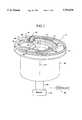
- FIG. 1is a perspective view of a centrifuge apparatus in accordance with the invention
- FIG. 2is a top view of the centrifuge apparatus depicted in FIG. 1;
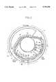
- FIG. 3is a detailed top view of a portion of the centrifuge apparatus of FIG. 2;
- FIG. 4is a perspective view of a tubing set for use with the invention.
- FIG. 5is a top view of the embodiment depicted in FIG. 1, including dimensions in accordance with the invention
- FIG. 7is a schematic cross-sectional view of the rotor illustrated in FIG. 1;
- FIG. 8is a schematic cross-sectional view of a rotor in accordance with an alternate embodiment of the present invention.
- FIG. 9is a partial top view of a further embodiment of the present invention.
- a preferred embodiment of the present inventionis described by referring to its use with a COBE® SPECTRATM two stage sealless blood component centrifuge manufactured by the assignee of the invention.
- the COBE® SPECTRATM centrifugeincorporates a one-omega/two-omega sealless tubing connection as disclosed in the above-mentioned U.S. Pat. No. 4,425,112 to Ito.
- the COBE® SPECTRATM centrifugealso uses a two-stage blood component separation channel substantially as disclosed in the above-mentioned U.S. Pat. No. 4,708,712 to Mulzet.
- the preferred embodiment of the inventionis described in combination with the COBE® SPECTRATM centrifuge, this description is not intended to limit the invention in any sense.
- the present inventionmay be advantageously used in a variety of centrifuge devices commonly used to separate blood into its components.
- the present inventionmay be used with any centrifugal apparatus that employs a component collect line such as a platelet collect line or a platelet rich plasma line, whether or not the apparatus employs a two stage channel or a one-omega/two-omega sealless tubing connection.
- centrifuge 10includes a disc-shaped filler plate or rotor 12.
- a motor 19is coupled to rotor 12 to rotate the rotor 12 about an axis of rotation 13. This coupling is accomplished directly or indirectly through a shaft 18 connected to the rotor 12. Alternately, the shaft 18 may be coupled to the motor 19 through a gearing transmission (not shown).
- a shroud 20is positioned on the rotor 12 to protect the motor 19 and shaft 18.
- the rotor 12may also include bracket 24 for maintaining a fluid chamber 22 on rotor 12 with a chamber outlet 32 generally positioned closer to the rotation axis 13 than a chamber inlet 28.
- a controller 40may be provided to vary the rotational speed of the centrifuge rotor 12 by regulating frequency, current, or voltage of the electricity applied to the motor 19.
- the rotor speedcan be varied by shifting the arrangement of a transmission (not shown), such as by changing gearing to alter a rotational coupling between the motor 19 and rotor 12.
- the controller 40may receive input from a rotational speed detector (not shown) to constantly monitor the rotor speed.
- a retainerassociated with the rotor and rotatable therewith, the retainer having an innermost wall spaced from the axis of rotation and an outermost wall located farther from the axis of rotation than the innermost wall, whereby the innermost wall and the outermost wall define a passageway therebetween.
- the retainerincludes an annular groove or passageway 14 in rotor 12.
- the passageway 14may be U-shaped in cross-section and adapted to receive a conduit or channel 44 of a tubing set 70, such as the semi-rigid plastic tube shown in FIG. 4.
- the passageway 14surrounds the rotor's axis of rotation 13 and is defined by a radially innermost wall 15 and a radially outermost wall 16. Both walls 15 and 16 extend through a top surface 17 of rotor 12.
- the retaineris a groove 14 formed in rotor 12
- any structure that forms a fixed passageway about the rotation axis 13may be used.
- the passageway 14may be configured with a closed rather than U-shaped cross-section in order to directly receive fluid flow in lieu of being lined by the conduit 44.
- passageway 14may be divided into three stages, each associated with collection of different blood components.
- a first stageextends from a groove 84 for a T-shaped connector 71 to a ridge 46 described in more detail below. This region is configured to collect red and white blood cells through outlet line 74.
- the second stageextends from ridge 46 to just before elbow 21. This region is configured to have a substantially constant inner wall radius forming a Coriolis-free path and for collecting platelets in collect well 54.
- the third stagewhich extends from elbow 21 to just before groove 84, is configured so that plasma may be collected through outlet line 72, received in slot 82.
- FIG. 5is a to-scale drawing containing the dimensions in inches ( ⁇ 0.005) of a preferred embodiment of the invention for use in connection with blood component separation.
- a preferred thickness of the rotor depicted in FIG. 5is 1.440 inches with a channel depth of 1.3 inches.
- the platelet collection well 54is downstream (relative to direction of plasma flow) from a dam 50 formed by ridge 46 in channel 44.
- the outermost wall 16 of passageway 14steeply slopes toward the outlet of well 54 for enhancing platelet collection.
- a first barrierformed in one of the passageway walls and extending toward and being spaced from the other of the passageway walls, the first barrier being sized to substantially block passage of materials in a first predetermined density range, and to substantially permit passage of materials outside of the predetermined density range.
- the ridge 48forms a protrusion positioned on the outermost wall 16 of passageway 14.
- ridge 48deforms a portion of the channel 44 to form dam 50 within the channel 44.
- the size of ridge 48may vary depending upon desired use. When used in connection with separation of blood components, ridge 48 may be sized, as shown in FIG. 3, to block passage of red and white blood cells and to permit passage of platelets and plasma. The mechanisms that provide for such selective passage of materials will be discussed in greater detail later in connection with the method of use of the invention.
- a second barrierformed in a wall of the retainer opposite the wall containing the first barrier, the second barrier being configured to block passage of fluid in a second density range to thereby maintain a substantially Coriolis-free pathway in a region of thus passageway adjacent the first barrier.
- the innermost wall 15 of passageway 14includes an indentation 51 positioned therein opposite ridge 48.
- pocket 52is sized to trap a low density fluid, such as saline or platelet poor plasma, during a priming procedure.
- This low density fluidforms a dome 59 in pocket 52 adjacent dam 50.
- the domewhich remains in pocket 52 during a separation procedure, effectively serves as a self-adjusting innermost flow boundary of the channel 44 opposite the dam 50. With this self-adjusting flow boundary, it is possible to maintain a substantially Coriolis-free pathway as fluid flows over the peak of dam 50, as is discussed later in greater detail.
- dam 50 and pocket 52may be permanent structures mounted within the flow passage of the channel 44. Although only a single dam 50 and pocket 52 are depicted in the figures, the flow passage may have multiple dams and pockets depending upon desired use. Likewise, while the figures depict a dam in the outermost wall 16 and a corresponding indentation in the innermost wall 15, the location of the dam and pocket may be reversed depending upon desired use.
- the second barrierneed not be an indentation in the innermost wall. It may be any type of blocking structure. As illustrated in FIG. 9, for example, the second barrier may be a protrusion 63 extending from the innermost wall and behind which a low density fluid becomes trapped. Similarly, the first barrier need not be a protrusion but, like the second barrier, may be any type of blocking structure.
- the step of introducing a priming fluid into a separator channelthe channel defining a fluid flow path and having a first barrier extending into the flow path and a second barrier in a channel wall opposite the first barrier.
- the separator channel 44is inserted in passageway 14 of rotor 12, as illustrated in FIG. 1, or the channel 44 and passageway 14 may be combined as a single element as illustrated in cross-section in FIG. 8.
- the passageway 14retains channel 44 of tubing set 70.
- tubing set 70preferably includes a semi-rigid conduit formed into a channel 44 having a generally rectangular cross-section.
- T-shaped connector 71joins ends of the channel 44 to form an annular or loop shape that fits within passageway 14.
- a supply line 78provides whole blood to an inlet of the semi-rigid channel 44, while a tubing segment 42, outlet lines 72, 74, and a control line 76 allow for removal of blood components during a centrifuge operation and flow control within the channel 44. Further details of the general configuration and functioning of the channel 44, tubing segment 42, and lines 72, 74, 76 and 78 are described in U.S. Pat. No. 4,708,712 to Mulzet.
- Channel 44is primed by introducing into channel 44 a priming fluid including at least a low density component that is capable of becoming entrapped by the second barrier.
- This priming fluidis preferably saline solution, but may also be blood.
- Priming fluidmay be introduced through inlet line 78 and withdrawn through one or more of outlet lines 42, 72, 74, and 76.
- the step of rotatingincludes turning rotor 12 about axis 13. This turning may be achieved by controller 40, which initiates operation of the motor 19 to rotate the centrifuge rotor 12 and fluid chamber 22 in the direction of arrow "B" in FIG. 3.
- the motor 19may rotate the rotor 12 and fluid chamber 22 in the opposite direction.
- rotationis properly defined by reference to the direction of platelet flow from the whole blood inlet to the platelet outlet. Rotation can, occur in either direction and still be within the scope of the invention.
- a pocket of low density fluidwhich, in the case of a blood separation process, may be saline or platelet poor plasma derived from blood, becomes trapped in pocket 52 of channel 44. This trapping occurs because the pocket 52 is recessed toward the axis of rotation 13.
- the rotor speed and density of the priming fluidare such that when blood pushes the priming fluid out of the passageway, the priming fluid in pocket 52 is unable to escape.
- a dome 59 of priming fluidforms opposite the dam 50.
- the indentation 51 and the protrusion 48are sized such that the dome 59 extends from the innermost wall 15 to the top of dam 50, contacting the peak of the dam 50.
- the fluid dome 59may extend just slightly below or above the top of the dam 50. Upstream of the dam 50, a bed 53 containing red and white blood cells is formed by dam 50. A platelet well 54 is formed downstream of the dam 50. Preferably, the dome extends over at least a portion of the blood cell bed 53 and the well 54.
- the separation fluidi.e. the fluid whose components are to be separated
- the separation fluidis whole blood provided to channel 44 through supply line 78. All of the components of whole blood have densities greater than the density of saline solution. Therefore, if saline solution is used to form the dome 59, all of the blood components will be centrifugally forced radially outward from the dome 59 as they flow in channel 44. If blood is used as the priming fluid, platelet poor plasma, the least dense component of blood, will form dome 59.
- platelet poor plasmamay include plasma carrying anywhere from zero to 700,000 platelets per cubic millimeter of plasma. However, the upper end of this range depends upon the concentration of platelets in the donors blood. Lower concentrations of platelets in the dome are preferable.
- dam 50is sized to substantially prevent the passage of red and white blood cells.
- the red and white blood cellsremain trapped behind dam 50, backing up from dam 50 all the way to groove 84 (FIG. 2) where they are withdrawn through outlet line 74 (FIG. 2).
- Platelets and plasmawhich have lower densities than red and white blood cells, stratify above the bed 53, as indicated by boundary line 57 in FIG. 3, and pass over the peak of dam 50.
- the higher density plateletsmigrate radially outward into platelet collection well 54 for removal through collection line 56.
- the outer wall of collection well 54has a significant slope causing platelets that pass well 54 to migrate back towards the well.
- the radius of innermost wall 15 of passageway 14decreases dramatically as the passageway approaches slot 82, where plasma is removed through outlet line 72.
- an outer edge of the dome 59forms an inner flow boundary, thereby maintaining a constant inner radial guide for plasma and platelets to flow along as they pass dam 50. Fluid flowing along a path of constant radius with respect to the center of rotation does not experience Coriolis accelerations and declerations. Therefore, by providing the constant inner radial boundary, a Coriolis-free pathway is formed.
- the constant inner radial boundaryserves to limit re-mixing of the platelets and plasma, which would otherwise occur if the radial orientation of the platelets and plasma were to change as they passed the dam. Re-mixing is limited because the dome 59 effectively acts as a self-adjusting "wall" minimizing radial movement of passing plasma and platelets.
- the constant radius inner wall of the second stageis sized substantially identical to the outer radius of the dome. The plasma and platelets flowing over the dam 50 push just enough of the dome 59 out of the way to enable flow over the dam 50 while still maintaining a substantially constant radial orientation.
- the dome 59will automatically adjust to accommodate varying volumes while maintaining a substantially Coriolis-free pathway.
- the dome 59also reduces the effective passageway volume in an area of the dam 50, the dome 59 induces higher plasma and platelet velocities in the first stage. Those higher velocities scrub sedimented platelets off of the cell bed 53, which further increases the efficiency of separation.
- an additional inner wall dam 65may be provided upstream of dam 50 as illustrated in FIG. 6. Dam 65 reduces the amount of space available for flow of plasma and platelets, thereby increasing their flow velocities upstream of dam 50.
- the priming fluid forming the dome 59may eventually be replaced by other fluids such as low density platelet pore plasma flowing in channel 44. Even when this replacement occurs, a fluid dome 59 is still maintained above the dam 50.
- the methodis described in connection with a blood component separation process, and as with the apparatus, it should be understood that the method of invention in its broadest sense is not limited to blood component separation. It has wide ranging industrial and medical applications.
- the inventionis applicable to both double needle and single needle blood processing applications.
- the inventionmay be practiced with the SINGLE NEEDLE RECIRCULATION SYSTEM FOR HARVESTING BLOOD COMPONENTS of U.S. Pat. No. 5,437,624, the disclosure of which is incorporated herein by reference.
Landscapes
- External Artificial Organs (AREA)
Abstract
Description
Claims (32)
Priority Applications (8)
| Application Number | Priority Date | Filing Date | Title |
|---|---|---|---|
| US08/648,503US5792038A (en) | 1996-05-15 | 1996-05-15 | Centrifugal separation device for providing a substantially coriolis-free pathway |
| JP09541072AJP2000510045A (en) | 1996-05-15 | 1997-05-12 | Method and apparatus for reducing turbulence in fluid flow |
| CA002255835ACA2255835A1 (en) | 1996-05-15 | 1997-05-12 | Method and apparatus for reducing turbulence in fluid flow |
| DE69702979TDE69702979T2 (en) | 1996-05-15 | 1997-05-12 | METHOD AND DEVICE FOR REDUCING TURBULENCES IN LIQUID FLOWS |
| EP97924704AEP0907420B1 (en) | 1996-05-15 | 1997-05-12 | Method and apparatus for reducing turbulence in fluid flow |
| PCT/US1997/008106WO1997043045A1 (en) | 1996-05-15 | 1997-05-12 | Method and apparatus for reducing turbulence in fluid flow |
| AU30057/97AAU3005797A (en) | 1996-05-15 | 1997-05-12 | Method and apparatus for reducing turbulence in fluid flow |
| US08/897,056US5954626A (en) | 1996-05-15 | 1997-07-18 | Method of minimizing coriolis effects in a centrifugal separation channel |
Applications Claiming Priority (1)
| Application Number | Priority Date | Filing Date | Title |
|---|---|---|---|
| US08/648,503US5792038A (en) | 1996-05-15 | 1996-05-15 | Centrifugal separation device for providing a substantially coriolis-free pathway |
Related Child Applications (1)
| Application Number | Title | Priority Date | Filing Date |
|---|---|---|---|
| US08/897,056DivisionUS5954626A (en) | 1996-05-15 | 1997-07-18 | Method of minimizing coriolis effects in a centrifugal separation channel |
Publications (1)
| Publication Number | Publication Date |
|---|---|
| US5792038Atrue US5792038A (en) | 1998-08-11 |
Family
ID=24601054
Family Applications (1)
| Application Number | Title | Priority Date | Filing Date |
|---|---|---|---|
| US08/648,503Expired - Fee RelatedUS5792038A (en) | 1996-05-15 | 1996-05-15 | Centrifugal separation device for providing a substantially coriolis-free pathway |
Country Status (1)
| Country | Link |
|---|---|
| US (1) | US5792038A (en) |
Cited By (24)
| Publication number | Priority date | Publication date | Assignee | Title |
|---|---|---|---|---|
| US5904645A (en)* | 1996-05-15 | 1999-05-18 | Cobe Laboratories | Apparatus for reducing turbulence in fluid flow |
| US6315707B1 (en) | 1999-09-03 | 2001-11-13 | Baxter International Inc. | Systems and methods for seperating blood in a rotating field |
| US6322488B1 (en) | 1999-09-03 | 2001-11-27 | Baxter International Inc. | Blood separation chamber with preformed blood flow passages and centralized connection to external tubing |
| US6334842B1 (en) | 1999-03-16 | 2002-01-01 | Gambro, Inc. | Centrifugal separation apparatus and method for separating fluid components |
| US6354986B1 (en) | 2000-02-16 | 2002-03-12 | Gambro, Inc. | Reverse-flow chamber purging during centrifugal separation |
| US20020077241A1 (en)* | 1999-09-03 | 2002-06-20 | Baxter International Inc. | Blood processing systems and methods with quick attachment of a blood separation chamber to a centrifuge rotor |
| US6524231B1 (en) | 1999-09-03 | 2003-02-25 | Baxter International Inc. | Blood separation chamber with constricted interior channel and recessed passage |
| US20030116512A1 (en)* | 2001-12-05 | 2003-06-26 | Glen Delbert Antwiler | Methods and apparatus for separation of particles |
| US20030232712A1 (en)* | 2002-06-14 | 2003-12-18 | Dolecek Victor D. | Centrifuge system utilizing disposable components and automated processing of blood to collect platelet rich plasma |
| US20040082459A1 (en)* | 2002-10-24 | 2004-04-29 | Baxter International Inc. | Blood processing systems and methods for collecting plasma free or essentially free of cellular blood components |
| US20040082458A1 (en)* | 1999-09-03 | 2004-04-29 | Baxter International Inc. | Blood processing systems and methods with umbilicus-driven blood processing chambers |
| US6736768B2 (en) | 2000-11-02 | 2004-05-18 | Gambro Inc | Fluid separation devices, systems and/or methods using a fluid pressure driven and/or balanced approach |
| US6890291B2 (en) | 2001-06-25 | 2005-05-10 | Mission Medical, Inc. | Integrated automatic blood collection and processing unit |
| US7037428B1 (en) | 2002-04-19 | 2006-05-02 | Mission Medical, Inc. | Integrated automatic blood processing unit |
| US20060205581A1 (en)* | 2005-03-09 | 2006-09-14 | Jacques Chammas | Automated system and method for blood components separation and processing |
| US20060240964A1 (en)* | 2005-04-21 | 2006-10-26 | Fresenius Hemocare Deutschland Gmbh | Method and apparatus for separation of particles suspended in a fluid |
| US7241281B2 (en) | 2002-04-08 | 2007-07-10 | Thermogenesis Corporation | Blood component separation method and apparatus |
| US7279107B2 (en) | 2002-04-16 | 2007-10-09 | Gambro, Inc. | Blood component processing system, apparatus, and method |
| US7297272B2 (en) | 2002-10-24 | 2007-11-20 | Fenwal, Inc. | Separation apparatus and method |
| US20080035585A1 (en)* | 2006-08-10 | 2008-02-14 | Gambro Bct, Inc. | Method and Apparatus for Recirculating Elutriation Fluids |
| US20080311651A1 (en)* | 2004-09-30 | 2008-12-18 | Coelho Philip H | Instrumentality for Sequestering Liquids Based on Density: Method and Apparatus |
| US8075468B2 (en) | 2008-02-27 | 2011-12-13 | Fenwal, Inc. | Systems and methods for mid-processing calculation of blood composition |
| US8685258B2 (en) | 2008-02-27 | 2014-04-01 | Fenwal, Inc. | Systems and methods for conveying multiple blood components to a recipient |
| US9248446B2 (en) | 2013-02-18 | 2016-02-02 | Terumo Bct, Inc. | System for blood separation with a separation chamber having an internal gravity valve |
Citations (35)
| Publication number | Priority date | Publication date | Assignee | Title |
|---|---|---|---|---|
| US2616619A (en)* | 1948-08-30 | 1952-11-04 | Norman A Macleod | Method and apparatus for centrifugal elutriation |
| US3825175A (en)* | 1973-06-06 | 1974-07-23 | Atomic Energy Commission | Centrifugal particle elutriator and method of use |
| US4010894A (en)* | 1975-11-21 | 1977-03-08 | International Business Machines Corporation | Centrifuge fluid container |
| US4091989A (en)* | 1977-01-04 | 1978-05-30 | Schlutz Charles A | Continuous flow fractionation and separation device and method |
| US4094461A (en)* | 1977-06-27 | 1978-06-13 | International Business Machines Corporation | Centrifuge collecting chamber |
| US4146172A (en)* | 1977-10-18 | 1979-03-27 | Baxter Travenol Laboratories, Inc. | Centrifugal liquid processing system |
| US4187979A (en)* | 1978-09-21 | 1980-02-12 | Baxter Travenol Laboratories, Inc. | Method and system for fractionating a quantity of blood into the components thereof |
| US4322298A (en)* | 1981-06-01 | 1982-03-30 | Advanced Blood Component Technology, Inc. | Centrifugal cell separator, and method of use thereof |
| US4350283A (en)* | 1980-07-01 | 1982-09-21 | Beckman Instruments, Inc. | Centrifugal elutriator rotor |
| US4356958A (en)* | 1977-07-19 | 1982-11-02 | The United States Of America As Represented By The Secretary Of Health And Human Services | Blood cell separator |
| US4386730A (en)* | 1978-07-21 | 1983-06-07 | International Business Machines Corporation | Centrifuge assembly |
| US4387848A (en)* | 1977-10-03 | 1983-06-14 | International Business Machines Corporation | Centrifuge assembly |
| US4419089A (en)* | 1977-07-19 | 1983-12-06 | The United States Of America As Represented By The Department Of Health And Human Services | Blood cell separator |
| US4425112A (en)* | 1976-02-25 | 1984-01-10 | The United States Of America As Represented By The Department Of Health And Human Services | Flow-through centrifuge |
| US4447221A (en)* | 1982-06-15 | 1984-05-08 | International Business Machines Corporation | Continuous flow centrifuge assembly |
| US4647279A (en)* | 1985-10-18 | 1987-03-03 | Cobe Laboratories, Inc. | Centrifugal separator |
| US4675117A (en)* | 1984-03-21 | 1987-06-23 | Fresenius Ag | Method of separating blood and apparatus for carrying out the method |
| US4708712A (en)* | 1986-03-28 | 1987-11-24 | Cobe Laboratories, Inc. | Continuous-loop centrifugal separator |
| US4708710A (en)* | 1986-03-27 | 1987-11-24 | E. I. Du Pont De Nemours And Company | Particle separation process |
| US4798579A (en)* | 1987-10-30 | 1989-01-17 | Beckman Instruments, Inc. | Rotor for centrifuge |
| EP0363120A2 (en)* | 1988-10-07 | 1990-04-11 | Baxter International Inc. | Centrifugal fluid processing system and method |
| US4934995A (en)* | 1977-08-12 | 1990-06-19 | Baxter International Inc. | Blood component centrifuge having collapsible inner liner |
| US4936820A (en)* | 1988-10-07 | 1990-06-26 | Baxter International Inc. | High volume centrifugal fluid processing system and method for cultured cell suspensions and the like |
| US4939087A (en)* | 1987-05-12 | 1990-07-03 | Washington State University Research Foundation, Inc. | Method for continuous centrifugal bioprocessing |
| US5006103A (en)* | 1977-08-12 | 1991-04-09 | Baxter International Inc. | Disposable container for a centrifuge |
| US5078671A (en)* | 1988-10-07 | 1992-01-07 | Baxter International Inc. | Centrifugal fluid processing system and method |
| US5217427A (en)* | 1977-08-12 | 1993-06-08 | Baxter International Inc. | Centrifuge assembly |
| US5316666A (en)* | 1987-01-30 | 1994-05-31 | Baxter International Inc. | Blood processing systems with improved data transfer between stationary and rotating elements |
| US5316667A (en)* | 1989-05-26 | 1994-05-31 | Baxter International Inc. | Time based interface detection systems for blood processing apparatus |
| US5360542A (en)* | 1991-12-23 | 1994-11-01 | Baxter International Inc. | Centrifuge with separable bowl and spool elements providing access to the separation chamber |
| US5362291A (en)* | 1991-12-23 | 1994-11-08 | Baxter International Inc. | Centrifugal processing system with direct access drawer |
| US5370802A (en)* | 1987-01-30 | 1994-12-06 | Baxter International Inc. | Enhanced yield platelet collection systems and methods |
| US5571068A (en)* | 1977-08-12 | 1996-11-05 | Baxter International Inc. | Centrifuge assembly |
| US5607830A (en)* | 1992-08-14 | 1997-03-04 | Fresenius Ag | Method for the continuous conditioning of a cell suspension |
| US5641414A (en)* | 1987-01-30 | 1997-06-24 | Baxter International Inc. | Blood processing systems and methods which restrict in flow of whole blood to increase platelet yields |
- 1996
- 1996-05-15USUS08/648,503patent/US5792038A/ennot_activeExpired - Fee Related
Patent Citations (35)
| Publication number | Priority date | Publication date | Assignee | Title |
|---|---|---|---|---|
| US2616619A (en)* | 1948-08-30 | 1952-11-04 | Norman A Macleod | Method and apparatus for centrifugal elutriation |
| US3825175A (en)* | 1973-06-06 | 1974-07-23 | Atomic Energy Commission | Centrifugal particle elutriator and method of use |
| US4010894A (en)* | 1975-11-21 | 1977-03-08 | International Business Machines Corporation | Centrifuge fluid container |
| US4425112A (en)* | 1976-02-25 | 1984-01-10 | The United States Of America As Represented By The Department Of Health And Human Services | Flow-through centrifuge |
| US4091989A (en)* | 1977-01-04 | 1978-05-30 | Schlutz Charles A | Continuous flow fractionation and separation device and method |
| US4094461A (en)* | 1977-06-27 | 1978-06-13 | International Business Machines Corporation | Centrifuge collecting chamber |
| US4356958A (en)* | 1977-07-19 | 1982-11-02 | The United States Of America As Represented By The Secretary Of Health And Human Services | Blood cell separator |
| US4419089A (en)* | 1977-07-19 | 1983-12-06 | The United States Of America As Represented By The Department Of Health And Human Services | Blood cell separator |
| US5571068A (en)* | 1977-08-12 | 1996-11-05 | Baxter International Inc. | Centrifuge assembly |
| US4934995A (en)* | 1977-08-12 | 1990-06-19 | Baxter International Inc. | Blood component centrifuge having collapsible inner liner |
| US5217427A (en)* | 1977-08-12 | 1993-06-08 | Baxter International Inc. | Centrifuge assembly |
| US5006103A (en)* | 1977-08-12 | 1991-04-09 | Baxter International Inc. | Disposable container for a centrifuge |
| US4387848A (en)* | 1977-10-03 | 1983-06-14 | International Business Machines Corporation | Centrifuge assembly |
| US4146172A (en)* | 1977-10-18 | 1979-03-27 | Baxter Travenol Laboratories, Inc. | Centrifugal liquid processing system |
| US4386730A (en)* | 1978-07-21 | 1983-06-07 | International Business Machines Corporation | Centrifuge assembly |
| US4187979A (en)* | 1978-09-21 | 1980-02-12 | Baxter Travenol Laboratories, Inc. | Method and system for fractionating a quantity of blood into the components thereof |
| US4350283A (en)* | 1980-07-01 | 1982-09-21 | Beckman Instruments, Inc. | Centrifugal elutriator rotor |
| US4322298A (en)* | 1981-06-01 | 1982-03-30 | Advanced Blood Component Technology, Inc. | Centrifugal cell separator, and method of use thereof |
| US4447221A (en)* | 1982-06-15 | 1984-05-08 | International Business Machines Corporation | Continuous flow centrifuge assembly |
| US4675117A (en)* | 1984-03-21 | 1987-06-23 | Fresenius Ag | Method of separating blood and apparatus for carrying out the method |
| US4647279A (en)* | 1985-10-18 | 1987-03-03 | Cobe Laboratories, Inc. | Centrifugal separator |
| US4708710A (en)* | 1986-03-27 | 1987-11-24 | E. I. Du Pont De Nemours And Company | Particle separation process |
| US4708712A (en)* | 1986-03-28 | 1987-11-24 | Cobe Laboratories, Inc. | Continuous-loop centrifugal separator |
| US5370802A (en)* | 1987-01-30 | 1994-12-06 | Baxter International Inc. | Enhanced yield platelet collection systems and methods |
| US5641414A (en)* | 1987-01-30 | 1997-06-24 | Baxter International Inc. | Blood processing systems and methods which restrict in flow of whole blood to increase platelet yields |
| US5316666A (en)* | 1987-01-30 | 1994-05-31 | Baxter International Inc. | Blood processing systems with improved data transfer between stationary and rotating elements |
| US4939087A (en)* | 1987-05-12 | 1990-07-03 | Washington State University Research Foundation, Inc. | Method for continuous centrifugal bioprocessing |
| US4798579A (en)* | 1987-10-30 | 1989-01-17 | Beckman Instruments, Inc. | Rotor for centrifuge |
| US5078671A (en)* | 1988-10-07 | 1992-01-07 | Baxter International Inc. | Centrifugal fluid processing system and method |
| US4936820A (en)* | 1988-10-07 | 1990-06-26 | Baxter International Inc. | High volume centrifugal fluid processing system and method for cultured cell suspensions and the like |
| EP0363120A2 (en)* | 1988-10-07 | 1990-04-11 | Baxter International Inc. | Centrifugal fluid processing system and method |
| US5316667A (en)* | 1989-05-26 | 1994-05-31 | Baxter International Inc. | Time based interface detection systems for blood processing apparatus |
| US5360542A (en)* | 1991-12-23 | 1994-11-01 | Baxter International Inc. | Centrifuge with separable bowl and spool elements providing access to the separation chamber |
| US5362291A (en)* | 1991-12-23 | 1994-11-08 | Baxter International Inc. | Centrifugal processing system with direct access drawer |
| US5607830A (en)* | 1992-08-14 | 1997-03-04 | Fresenius Ag | Method for the continuous conditioning of a cell suspension |
Non-Patent Citations (9)
| Title |
|---|
| As 104 Cell Separator, Fresenius.* |
| Brief Operating Instructions, Fresenius MT AS 104 blood cell separator, 4/6.90 (OP).* |
| CS 3000 Blood Cell Separator, Powerful Technology, Fenwal Laboratories.* |
| CS-3000 Blood Cell Separator, Powerful Technology, Fenwal Laboratories. |
| J.F. Jemionek, Variations in CCE Protocol for Cell Isolation, Elutriation, pp. 17 41.* |
| J.F. Jemionek, Variations in CCE Protocol for Cell Isolation, Elutriation, pp. 17-41. |
| Multi Chamber Counterflow Centrifugation System, Dijkstra Vereenigde B.V., 6 pp.* |
| Robert J. Grabske, Separating Cell Populations by Elutriation, pp. 1 8.* |
| Robert J. Grabske, Separating Cell Populations by Elutriation, pp. 1-8. |
Cited By (59)
| Publication number | Priority date | Publication date | Assignee | Title |
|---|---|---|---|---|
| US5904645A (en)* | 1996-05-15 | 1999-05-18 | Cobe Laboratories | Apparatus for reducing turbulence in fluid flow |
| US7029430B2 (en) | 1999-03-16 | 2006-04-18 | Gambro, Inc. | Centrifugal separation apparatus and method for separating fluid components |
| US7549956B2 (en) | 1999-03-16 | 2009-06-23 | Caridianbct, Inc. | Centrifugal separation apparatus and method for separating fluid components |
| US6334842B1 (en) | 1999-03-16 | 2002-01-01 | Gambro, Inc. | Centrifugal separation apparatus and method for separating fluid components |
| US6514189B1 (en) | 1999-03-16 | 2003-02-04 | Gambro, Inc. | Centrifugal separation method for separating fluid components |
| US20020077241A1 (en)* | 1999-09-03 | 2002-06-20 | Baxter International Inc. | Blood processing systems and methods with quick attachment of a blood separation chamber to a centrifuge rotor |
| US20040082458A1 (en)* | 1999-09-03 | 2004-04-29 | Baxter International Inc. | Blood processing systems and methods with umbilicus-driven blood processing chambers |
| US6524231B1 (en) | 1999-09-03 | 2003-02-25 | Baxter International Inc. | Blood separation chamber with constricted interior channel and recessed passage |
| US7789245B2 (en) | 1999-09-03 | 2010-09-07 | Fenwal, Inc. | Blood separation chamber |
| US20030203802A1 (en)* | 1999-09-03 | 2003-10-30 | Baxter International Inc. | Blood separation chamber with preformed blood flow passages and centralized connection to external tubing |
| US6322488B1 (en) | 1999-09-03 | 2001-11-27 | Baxter International Inc. | Blood separation chamber with preformed blood flow passages and centralized connection to external tubing |
| US7166231B2 (en) | 1999-09-03 | 2007-01-23 | Baxter International Inc. | Red blood cell separation method |
| US6860846B2 (en) | 1999-09-03 | 2005-03-01 | Baxter International Inc. | Blood processing systems and methods with umbilicus-driven blood processing chambers |
| US6315707B1 (en) | 1999-09-03 | 2001-11-13 | Baxter International Inc. | Systems and methods for seperating blood in a rotating field |
| US6800054B2 (en) | 1999-09-03 | 2004-10-05 | Baxter International Inc. | Blood separation chamber with preformed blood flow passages and centralized connection to external tubing |
| US6354986B1 (en) | 2000-02-16 | 2002-03-12 | Gambro, Inc. | Reverse-flow chamber purging during centrifugal separation |
| US6773389B2 (en) | 2000-11-02 | 2004-08-10 | Gambro Inc | Fluid separation devices, systems and/or methods using a fluid pressure driven and/or balanced configuration |
| US6736768B2 (en) | 2000-11-02 | 2004-05-18 | Gambro Inc | Fluid separation devices, systems and/or methods using a fluid pressure driven and/or balanced approach |
| US7094197B2 (en) | 2000-11-02 | 2006-08-22 | Gambro, Inc. | Method for fluid separation devices using a fluid pressure balanced configuration |
| US7094196B2 (en) | 2000-11-02 | 2006-08-22 | Gambro Inc. | Fluid separation methods using a fluid pressure driven and/or balanced approach |
| US7115205B2 (en) | 2001-06-25 | 2006-10-03 | Mission Medical, Inc. | Method of simultaneous blood collection and separation using a continuous flow centrifuge having a separation channel |
| US6890291B2 (en) | 2001-06-25 | 2005-05-10 | Mission Medical, Inc. | Integrated automatic blood collection and processing unit |
| US7695423B2 (en) | 2001-06-25 | 2010-04-13 | Terumo Medical Corporation | Method of simultaneous blood collection and separation using a continuous flow centrifuge having a separation channel |
| US7201848B2 (en) | 2001-12-05 | 2007-04-10 | Gambro Bct, Inc. | Methods and apparatus for separation of particles |
| US20050250204A1 (en)* | 2001-12-05 | 2005-11-10 | Gambro, Inc. | Methods and apparatus for separation of particles |
| US20030116512A1 (en)* | 2001-12-05 | 2003-06-26 | Glen Delbert Antwiler | Methods and apparatus for separation of particles |
| US7588692B2 (en) | 2001-12-05 | 2009-09-15 | Caridianbct, Inc. | Methods for separation of particles |
| US20070144978A1 (en)* | 2001-12-05 | 2007-06-28 | Gambro Bct Inc. | Methods and Apparatus for Separation of Particles |
| US7241281B2 (en) | 2002-04-08 | 2007-07-10 | Thermogenesis Corporation | Blood component separation method and apparatus |
| US8167139B2 (en) | 2002-04-08 | 2012-05-01 | Thermogenesis Corp. | Stem and progenitor cell compositions recovered from bone marrow or cord blood; system and method for preparation thereof |
| US20070269887A1 (en)* | 2002-04-08 | 2007-11-22 | Coelho Philip H | Stem and progenitor cell compositions recovered from bone marrow or cord blood; system and method for preparation thereof |
| US7708889B2 (en) | 2002-04-16 | 2010-05-04 | Caridianbct, Inc. | Blood component processing system method |
| US7497944B2 (en) | 2002-04-16 | 2009-03-03 | Caridianbct, Inc. | Blood component processing system, apparatus, and method |
| US7279107B2 (en) | 2002-04-16 | 2007-10-09 | Gambro, Inc. | Blood component processing system, apparatus, and method |
| US7531098B2 (en) | 2002-04-19 | 2009-05-12 | Terumo Medical Corporation | Integrated automatic blood processing unit |
| US7037428B1 (en) | 2002-04-19 | 2006-05-02 | Mission Medical, Inc. | Integrated automatic blood processing unit |
| US20070045201A1 (en)* | 2002-06-14 | 2007-03-01 | Dolecek Victor D | Centrifuge system utilizing disposable components and automated processing of blood to collect platelet rich plasma |
| US7252758B2 (en) | 2002-06-14 | 2007-08-07 | Medtronic, Inc. | Centrifuge system utilizing disposable components and automated processing of blood to collect platelet rich plasma |
| US7306555B2 (en) | 2002-06-14 | 2007-12-11 | Medtronic, Inc. | Centrifuge system utilizing disposable components and automated processing of blood to collect platelet rich plasma |
| US20060124561A1 (en)* | 2002-06-14 | 2006-06-15 | Medtronic, Inc. | Centrifuge system utilizing disposable components and automated processing of blood to collect platelet rich plasma |
| US7867159B2 (en) | 2002-06-14 | 2011-01-11 | Arteriocyte Medical Systems, Inc. | Centrifuge system utilizing disposable components and automated processing of blood to collect platelet rich plasma |
| US20030232712A1 (en)* | 2002-06-14 | 2003-12-18 | Dolecek Victor D. | Centrifuge system utilizing disposable components and automated processing of blood to collect platelet rich plasma |
| US6982038B2 (en) | 2002-06-14 | 2006-01-03 | Medtronic, Inc. | Centrifuge system utilizing disposable components and automated processing of blood to collect platelet rich plasma |
| US7918350B2 (en) | 2002-10-24 | 2011-04-05 | Fenwal, Inc. | Separation apparatus and method |
| US20040082459A1 (en)* | 2002-10-24 | 2004-04-29 | Baxter International Inc. | Blood processing systems and methods for collecting plasma free or essentially free of cellular blood components |
| US7297272B2 (en) | 2002-10-24 | 2007-11-20 | Fenwal, Inc. | Separation apparatus and method |
| US6849039B2 (en)* | 2002-10-24 | 2005-02-01 | Baxter International Inc. | Blood processing systems and methods for collecting plasma free or essentially free of cellular blood components |
| US8066127B2 (en) | 2004-09-30 | 2011-11-29 | Thermogenesis Corp. | Instrumentality for sequestering liquids based on density:method and apparatus |
| US20080311651A1 (en)* | 2004-09-30 | 2008-12-18 | Coelho Philip H | Instrumentality for Sequestering Liquids Based on Density: Method and Apparatus |
| US7442178B2 (en) | 2005-03-09 | 2008-10-28 | Jacques Chammas | Automated system and method for blood components separation and processing |
| US20060205581A1 (en)* | 2005-03-09 | 2006-09-14 | Jacques Chammas | Automated system and method for blood components separation and processing |
| US20080248938A1 (en)* | 2005-03-09 | 2008-10-09 | Jacques Chammas | Automated system and method for blood components separation and processing |
| US8876683B2 (en) | 2005-03-09 | 2014-11-04 | Jacques Chammas | Automated system and method for blood components separation and processing |
| US20060240964A1 (en)* | 2005-04-21 | 2006-10-26 | Fresenius Hemocare Deutschland Gmbh | Method and apparatus for separation of particles suspended in a fluid |
| US7473216B2 (en)* | 2005-04-21 | 2009-01-06 | Fresenius Hemocare Deutschland Gmbh | Apparatus for separation of a fluid with a separation channel having a mixer component |
| US20080035585A1 (en)* | 2006-08-10 | 2008-02-14 | Gambro Bct, Inc. | Method and Apparatus for Recirculating Elutriation Fluids |
| US8075468B2 (en) | 2008-02-27 | 2011-12-13 | Fenwal, Inc. | Systems and methods for mid-processing calculation of blood composition |
| US8685258B2 (en) | 2008-02-27 | 2014-04-01 | Fenwal, Inc. | Systems and methods for conveying multiple blood components to a recipient |
| US9248446B2 (en) | 2013-02-18 | 2016-02-02 | Terumo Bct, Inc. | System for blood separation with a separation chamber having an internal gravity valve |
Similar Documents
| Publication | Publication Date | Title |
|---|---|---|
| US5792038A (en) | Centrifugal separation device for providing a substantially coriolis-free pathway | |
| US5904645A (en) | Apparatus for reducing turbulence in fluid flow | |
| CA1298822C (en) | Continuous-loop centrifugal separator | |
| US7549956B2 (en) | Centrifugal separation apparatus and method for separating fluid components | |
| CA1295593C (en) | Centrifugal separator | |
| US6354986B1 (en) | Reverse-flow chamber purging during centrifugal separation | |
| EP1000664B1 (en) | Particle separation apparatus and method | |
| US5573678A (en) | Blood processing systems and methods for collecting mono nuclear cells | |
| CA2522090C (en) | Apparatus, and method for separation of fluid components | |
| EP0907420B1 (en) | Method and apparatus for reducing turbulence in fluid flow | |
| EP1871507A2 (en) | Method and apparatus for separation of particles suspended in a fluid | |
| US20030173274A1 (en) | Blood component separation device, system, and method including filtration | |
| MXPA99011979A (en) | Systems and methods for collecting diluted mononuclear cells | |
| HU196919B (en) | Blood separator | |
| MXPA99011977A (en) | Systems and methods for harvesting mononuclear cells by recirculation of packed red blood cells |
Legal Events
| Date | Code | Title | Description |
|---|---|---|---|
| AS | Assignment | Owner name:COBE LABORATORIES, INC., COLORADO Free format text:ASSIGNMENT OF ASSIGNORS INTEREST;ASSIGNOR:HLAVINKA, DENNIS;REEL/FRAME:008157/0800 Effective date:19960718 | |
| AS | Assignment | Owner name:GAMBRO, INC., COLORADO Free format text:CHANGE OF NAME;ASSIGNOR:COBE LABORATORIES, INC.;REEL/FRAME:011190/0225 Effective date:19991221 | |
| FPAY | Fee payment | Year of fee payment:4 | |
| FPAY | Fee payment | Year of fee payment:8 | |
| AS | Assignment | Owner name:CITICORP TRUSTEE COMPANY LIMITED, AS SECURITY AGEN Free format text:SECURITY AGREEMENT;ASSIGNOR:GAMBRO, INC.;REEL/FRAME:018552/0717 Effective date:20061117 | |
| AS | Assignment | Owner name:GAMBRO BCT, INC.,COLORADO Free format text:ASSIGNMENT OF ASSIGNORS INTEREST;ASSIGNOR:GAMBRO, INC.;REEL/FRAME:018787/0264 Effective date:20061218 Owner name:GAMBRO BCT, INC., COLORADO Free format text:ASSIGNMENT OF ASSIGNORS INTEREST;ASSIGNOR:GAMBRO, INC.;REEL/FRAME:018787/0264 Effective date:20061218 | |
| AS | Assignment | Owner name:CARIDIANBCT, INC., COLORADO Free format text:CHANGE OF NAME;ASSIGNOR:GAMBRO BCT, INC.;REEL/FRAME:021301/0114 Effective date:20080714 | |
| REMI | Maintenance fee reminder mailed | ||
| LAPS | Lapse for failure to pay maintenance fees | ||
| STCH | Information on status: patent discontinuation | Free format text:PATENT EXPIRED DUE TO NONPAYMENT OF MAINTENANCE FEES UNDER 37 CFR 1.362 | |
| FP | Lapsed due to failure to pay maintenance fee | Effective date:20100811 | |
| AS | Assignment | Owner name:GAMBRO, INC., COLORADO Free format text:RELEASE BY SECURED PARTY;ASSIGNOR:CITICORP TRUSTEE COMPANY LIMITED, AS SECURITY AGENT;REEL/FRAME:026209/0914 Effective date:20110413 Owner name:CARIDIANBCT, INC., COLORADO Free format text:RELEASE BY SECURED PARTY;ASSIGNOR:CITICORP TRUSTEE COMPANY LIMITED, AS SECURITY AGENT;REEL/FRAME:026209/0890 Effective date:20110413 |