US5790958A - Radio reception system for general purpose computer - Google Patents
Radio reception system for general purpose computerDownload PDFInfo
- Publication number
- US5790958A US5790958AUS08/543,317US54331795AUS5790958AUS 5790958 AUS5790958 AUS 5790958AUS 54331795 AUS54331795 AUS 54331795AUS 5790958 AUS5790958 AUS 5790958A
- Authority
- US
- United States
- Prior art keywords
- data
- digital
- general purpose
- audio signal
- radio
- Prior art date
- Legal status (The legal status is an assumption and is not a legal conclusion. Google has not performed a legal analysis and makes no representation as to the accuracy of the status listed.)
- Expired - Lifetime
Links
- 238000012545processingMethods0.000claimsabstractdescription46
- 238000000034methodMethods0.000claimsabstractdescription36
- 230000005540biological transmissionEffects0.000claimsabstractdescription28
- 230000008569processEffects0.000claimsabstractdescription12
- 230000005236sound signalEffects0.000claimsdescription29
- 238000012546transferMethods0.000claimsdescription21
- 238000004891communicationMethods0.000claimsdescription3
- 239000000284extractSubstances0.000claims5
- 230000000977initiatory effectEffects0.000claims2
- 230000011664signalingEffects0.000claims1
- 230000006870functionEffects0.000abstractdescription24
- 208000011580syndromic diseaseDiseases0.000description20
- 230000000694effectsEffects0.000description13
- 238000004364calculation methodMethods0.000description6
- 230000008901benefitEffects0.000description5
- 238000012937correctionMethods0.000description4
- 238000010586diagramMethods0.000description4
- 230000009977dual effectEffects0.000description3
- 230000009471actionEffects0.000description2
- 230000001413cellular effectEffects0.000description2
- 238000001514detection methodMethods0.000description2
- 238000002372labellingMethods0.000description2
- 230000001360synchronised effectEffects0.000description2
- 238000004458analytical methodMethods0.000description1
- 239000000470constituentSubstances0.000description1
- 238000013481data captureMethods0.000description1
- 238000005516engineering processMethods0.000description1
- 230000003993interactionEffects0.000description1
- 238000004886process controlMethods0.000description1
- 238000003672processing methodMethods0.000description1
- 230000000644propagated effectEffects0.000description1
- 238000006467substitution reactionMethods0.000description1
- 230000001960triggered effectEffects0.000description1
- 230000000007visual effectEffects0.000description1
Images


Classifications
- H—ELECTRICITY
- H04—ELECTRIC COMMUNICATION TECHNIQUE
- H04H—BROADCAST COMMUNICATION
- H04H60/00—Arrangements for broadcast applications with a direct linking to broadcast information or broadcast space-time; Broadcast-related systems
- H04H60/27—Arrangements for recording or accumulating broadcast information or broadcast-related information
- H—ELECTRICITY
- H04—ELECTRIC COMMUNICATION TECHNIQUE
- H04H—BROADCAST COMMUNICATION
- H04H20/00—Arrangements for broadcast or for distribution combined with broadcast
- H04H20/28—Arrangements for simultaneous broadcast of plural pieces of information
- H04H20/33—Arrangements for simultaneous broadcast of plural pieces of information by plural channels
- H04H20/34—Arrangements for simultaneous broadcast of plural pieces of information by plural channels using an out-of-band subcarrier signal
- H—ELECTRICITY
- H04—ELECTRIC COMMUNICATION TECHNIQUE
- H04H—BROADCAST COMMUNICATION
- H04H20/00—Arrangements for broadcast or for distribution combined with broadcast
- H04H20/53—Arrangements specially adapted for specific applications, e.g. for traffic information or for mobile receivers
- H—ELECTRICITY
- H04—ELECTRIC COMMUNICATION TECHNIQUE
- H04H—BROADCAST COMMUNICATION
- H04H2201/00—Aspects of broadcast communication
- H04H2201/10—Aspects of broadcast communication characterised by the type of broadcast system
- H04H2201/13—Aspects of broadcast communication characterised by the type of broadcast system radio data system/radio broadcast data system [RDS/RBDS]
- H—ELECTRICITY
- H04—ELECTRIC COMMUNICATION TECHNIQUE
- H04H—BROADCAST COMMUNICATION
- H04H2201/00—Aspects of broadcast communication
- H04H2201/70—Aspects of broadcast communication characterised in that receivers can be addressed
Definitions
- This inventionrelates generally to apparatus for receiving and decoding modulated data transmitted over a radio broadcast. More specifically, this invention relates to apparatus and methods which are capable of decoding and processing digital and analog information transmitted over an FM frequency using a personal computer.
- the United Stateshas developed a Radio Broadcast Data System (RBDS) standard for encoding digital data to allow transmission of the digital data on an FM carrier propagated over the airwaves.
- Radio stations, and other Radio Frequency (RF) generating sitesuse the RBDS standard to transmit digital data to recipients of a corresponding FM signal.
- the RBDS datais transmitted on a subcarrier within an FM broadcaster's allocated bandwidth.
- the subcarrieris locked in phase to the third harmonic of the 19 kHz pilot tone in stereo broadcasts and located at 57 kHz in mono broadcasts.
- the encoding and decoding specification for the "United States RBDS Standard”has been published by the National Radio Systems Committee on Jan. 8, 1993, the entire contents of which, including the Appendices, is incorporated herein by reference as though fully set forth.
- a copy of the RBDS standard publicationcan be obtained by contacting the National Association of Broadcasters located at 1771 N. Street, N.W., Washington, D.C. 20036.
- the RBDS standardencompasses several data broadcast and data technologies including the Radio Data System (RDS) and the Telecommunications Specification known as "MBS", both originally developed in Europe. Either of the RDS or MBS standards can be used to encode and decode digital data on an FM multiplexed signal for transmission and reception, respectively, over the airwaves.
- RDSRadio Data System
- MBSTelecommunications Specification
- RDS and MBS standardsdiffer in the way digital data is configured or formatted for transmission.
- Data transmitted via RDSis separated into various segments, called “groups", wherein each group represents a specific type of information, such as traffic information, emergency information, station information, etc.
- groupswherein each group represents a specific type of information, such as traffic information, emergency information, station information, etc.
- data transmitted via MBSis not specifically segmented and thus its transmission format can be customized according to the needs of a station operator.
- RDS and MBS methodsare in use in the United States by various radio stations.
- Data transmission by the RDS methodallows radio stations to transmit pertinent information related to the FM signal such as station call letters, song titles, music type, etc. Since this information is transmitted under the known RDS format, the data can be captured and then decoded using the RBDS standard specification.
- Some of the more sophisticated car radioshave an RDS data decoding capability.
- MBS data transmissionis also used by various radio stations across North America.
- One group of nationwide stationsutilizes MBS transmission to create a paging network based on FM radio.
- Such a systemoperates similarly to cellular paging networks, except that the paging signal is transmitted via FM radio.
- an MBS digital signalis broadcast over the network of radio stations. Since MBS data is uniquely formatted by the sending station, it is only useful to those MBS receivers which are programmed to decipher a particular transmission.
- RBDS data transmission methodsUse of the RBDS data transmission methods is one way a provider of information can transmit data over a wide geographical region to millions of potential recipients.
- Traditional methods for transmitting digital data to a large number of peopleinclude those which operate over the telephone lines.
- Such methodsare commonly termed "on-line” services such as Compuserve® or America On-Line.
- Today's personal computers (PCs)have an ever-expanding range of memory capacity and processing power which makes these services valuable informational tools.
- PCspersonal computers
- Such on-line serviceshave a monthly fee and usage charge for access to the large database of information on such services.
- the PC user who accesses an on-line servicemay be seeking only "basic" services such as weather information, stock market information, traffic information, or the current news.
- basic servicessuch as weather information, stock market information, traffic information, or the current news.
- the present inventioncombines a radio data reception system with a personal computer.
- the radio data reception systemreceives FM broadcasts and decodes digital data modulated along with the FM broadcasts. Receipt of FM radio data within a personal computer allows a user to take advantage of the processing and storage capability of modern personal computers.
- An FM stereo tuneris included to provide the user with full stereo functionality in addition to radio data reception.
- the radio data reception systemoperates in accordance with the RBDS standard to receive both RDS and MBS data.
- the radio data reception systemcontains its own microprocessor which can automatically synchronize and interpret either RDS or MBS data. Operation of the radio data reception system is performed either manually through user interaction, or automatically based on predetermined settings.
- the radio data reception systemcan operate in one of several user-selectable modes.
- a first mode of operationis that of a stereo tuner in which full stereo functions are presented to a user on a monitor.
- the usermay store audio information directly to a host computer or other associated system.
- the radio data reception systemWhile in the stereo tuner mode, the radio data reception system will read and decode any RDS data transmitted by the particular radio station which is tuned by the user. This RDS data is then processed and displayed to the user.
- a second mode of operation for the radio data reception systemis a page receiving mode in which the radio data reception system receives and processes MBS formatted data.
- the personal computercan receive a page and because of the processing and storage capability of personal computers, large amounts of information transmitted with the page can be instantly displayed to the user or stored for later retrieval.
- the paging modeis particularly advantageous for users who travel and operate laptop or portable computers. Moreover, depending on the particular transmitting stations, a much wider paging service area can be offered over traditional cellular pagers.
- a third mode of operation for the radio data reception systemis an MBS data receipt and storage mode.
- MBS data receipt and storage modeunlike the MBS paging mode, digital data is continuously read, processed and stored by the host computer.
- internal programming of the radio data reception systemdecodes and formats the MBS data in accordance with the encoding method used by the associated radio station. This allows for proprietary information transfer to users of the radio data reception system.
- Transfer of data in this third modecan be coordinated with existing MBS stations which currently transmit paging information.
- FM paging radio stationstypically have peak paging hours during morning and afternoon rush hours. Other portions of the day and night having little or no paging activity. These time periods can be used to transmit additional information to a user of the radio data reception system. Such information can include items currently available on popular on-line services, such as news and weather reports.
- the radio data reception systemcan decode both RDS or MBS data, the system can operate in multiple modes simultaneously to detect both RDS and MBS data which may be multiplexed and transmitted by a single radio station.
- An alternative embodiment of the present inventionuses a plurality of tuners enabling the user to receive multiple FM radio signals at the same time. This also allows the user to operate the radio data reception system in multiple modes while maintaining maximum data throughput. Thus, a user could be listening to the radio, listening for a page, or downloading news and other information concurrently.
- the capabilities of personal computers and other personal processing devicesallows for effective dual-tuner operation of the radio data reception system.
- FIG. 1is a perspective view of a personal computer having a radio data reception system for receiving data signals over the airwaves.
- FIG. 2is a diagram depicting a segment of RBDS data and its component blocks.
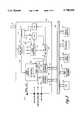
- FIG. 3is a schematic block diagram depicting the components of a radio data reception system for use in a personal computer.
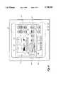
- FIG. 4is a diagram of a user display generated by a radio data reception system for use in a personal computer.
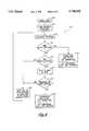
- FIG. 5is a flow chart depicting the functions performed by the microcode instructions of a radio data reception system for use in a personal computer.
- FIG. 6is a detailed flow chart of the initial data synchronization process performed by a radio data reception system for use in a personal computer.
- FIG. 7is a flow chart depicting the functions performed by the application software of a radio data reception system for use in a personal computer.
- FIG. 8is a schematic block diagram of an alternative embodiment for a radio data reception system having multiple FM tuners and data decoders for use in a personal computer.
- FIG. 1is a perspective view of a personal computer 20 having a housing 22 which is connected to a monitor 24 and a keyboard 26.
- the housing 22contains a motherboard 28 upon which various circuit components 30 of the computer 20 are mounted.
- a radio data reception systemcomprising an FM tuner and digital data decoder card 40 is connected to the motherboard 28 as shown.
- a reception antenna 42is attached to the data decoder card 40 for receiving FM signals transmitted over the airwaves from a second antenna 44.
- FM signalsmay be processed by the computer 20 for playback of audio signals through a pair of speakers 46 attached to the computer 20.
- the computer 20also processes any RDS or MBS digital data received from the FM transmission. This data may be displayed on the monitor 24 to an operator.
- the content of the digital data received by the card 40is determined by the particular FM signal received, and is later decoded according to the Radio Broadcast Data System (RBDS) standard used by various radio stations.
- RBDSRadio Broadcast Data System
- the MBS standardmay also be used by FM stations to transmit data in the form of paging information, daily news, etc., over the airwaves to a computer which is equipped with the radio data reception system disclosed herein. Accordingly, the present invention creates a complete FM stereo tuner and RBDS data decoding system within a personal computer.
- Digital data transmitted using the RBDS systemis formatted as a Radio Data System (RDS) segment or an MBS segment.
- RDSRadio Data System
- Individual RDS data bitsare configured in a specific format consisting of 104-bit groups comprised of four 26-bit blocks. In the RDS standard, there can be a total of 16 separate group types each representing different types of information.
- the various 104-bit group types which are currently defined in the RDS standardare listed below:
- FIG. 2depicts a standard RDS group of digital data and its constituent blocks.
- a specific 104-bit group type 50there are four consecutive blocks labelled A, B, C or C', and D. Each block contains a 16-bit information word 52 and a 10-bit checkword 54.
- the RDS standardsets forth a specific message format and addressing scheme for the various group types. For example, the overall group type 50 is determined by the first four bits of block B while the first sixteen bits of block A represent a particular station's program identification code.
- the radio data reception systemcomprises the FM tuner and processing card 40 which is connected via a bus 60, such as an ISA bus, to the components of a personal computer.
- the main personal computer componentsinclude a central processing unit (CPU) 62, a RAM memory unit 64, a mass storage unit 66 such as a hard disk drive, a keyboard 68, and a monitor 70. It is also possible to externally mount the card 40 outside of the personal computer 20 (shown in FIG. 1) and connect the card 40 to the computer 20 via an external interface.
- the processing card 40interfaces with the bus 60 through a group of interrupt lines 72 and a group of address and data lines 74.
- the card 40comprises a receiver and tuner unit 74 which is connected to an antenna 76.
- the receiver 74is connected to a digital data decoder 78 which is in turn connected to a digital data processor, or microcontroller 80.
- the receiver 74is also connected to an audio processing unit 82, an analog to digital converter 84, and a phased loop logic (PLL) circuit 84.
- a local bus controller 88such as an I 2 C bus master, is connected to the devices 80, 82, 84, and 86 as shown, and is also connected to address decoding circuitry 90.
- the address decoding circuitry 90 and interrupt decoding circuitry 92are both connected to the microcontroller 80.
- the card 40also contains an external serial port 93 connected to the microcontroller 80, and three audio ports, labelled A-C, connected to the audio processing unit 82.
- Audio port Ais an audio-output port for connection to external speakers
- audio port Bis an unprocessed audio port for connection to a sound card or other audio device
- audio port Cis an input port or "line-in" port for receiving audio signals to be processed by the audio unit 82.
- the processing card 40performs stand-alone functions dictated by software, or microcode 95, which is resident within the microcontroller 80.
- the microcontroller 80may be a standard 8051 device operating at 12 megahertz. Additional functions of the card 40, as well as processing functions of the radio data reception system, are controlled by application software 97 resident in the associated PC which may be stored in the mass storage device 66 and loaded into the PC's memory unit 64 during operation.
- Communication between the various devices of the card 40is accomplished via a local 2-bit I 2 C bus.
- local bus accessis controlled through the I 2 C bus master chip 88.
- I 2 C bus master chip 88Although the embodiment shown in FIG. 3 uses a specific I 2 C bus master, it is possible to configure the microcontroller 80 as the bus master thereby eliminating the need for a separate bus master chip 88.
- Tuning information received from the application software 97, via the bus 60,is routed through the I 2 C bus master 88 and to the PLL 86.
- audio processing parametersare routed to the audio processing unit 82 via the bus master 88.
- the receiver 74locks on to the desired FM station and emits corresponding signals along paths 94, 96 and 98.
- the data path 94Three separate signals are transmitted indicating the strength of the detected audio signal and the levels of the left and right stereo signals. This information is then digitized by the A/D converter 84 and then transferred back through the bus 60 for processing and display by the application software 97.
- the signal containing the analog audio informationis transmitted along the path 96 for further processing by the circuitry 82 before being output to the audio port A.
- the audio signalis also transmitted along path 98 to the digital data decoder 78.
- the digital data decoder 98demodulates and decodes the digital RBDS data (either RDS or MBS) associated with the particular FM stationed which is tuned by the receiver 74.
- the digital data decoder 78may be any number of standard decoding devices. In a preferred embodiment, a Phillips brand model SA6574T is used.
- the decoder 78outputs a continuous digital data stream, and corresponding clock signal, along a path 100 which is received by the microcontroller 80 for analysis and processing.
- the microprocessorperforms a sequence of operations to identify, decode, store, and eventually transmit the RDS or MBS data along the bus 60 to the host computer.
- the microcontroller 80if the microcontroller 80 detects RDS data, it will automatically decode the various data groups of RDS data outlined in Table I above. Similarly, if the microcontroller 80 detects MBS data, it will automatically decode the data as defined by the appropriate MBS data structure.
- Communication between the microcontroller 80 and the host personal computer, or other display/processing system,is accomplished via a status port having corresponding signal lines 104, and a data port having corresponding signal lines 106.
- the data and status portsmay be on-board, or implemented with an external I/O device.
- the data and status portsare 8-bit registers and the signal lines 104 and 106 each contain a corresponding 8 individual signal paths.
- the status signal lines 104serve to identify the current transfer operation performed by the microcontroller 80, and the data signal lines 106 transfer the data from the microcontroller 80 to the host computer.
- the data and status information from the corresponding portsis decoded by the address decoding circuitry 90 and presented to the bus 60 for transfer to the host computer.
- Interrupt decoding informationis transferred from the microcontroller 80 to the interrupt decoding circuitry 92 along a path 102.
- interrupt signalsare processed by the decoding circuitry 92 and presented to the bus 60 over the signal lines 72.
- Data transfer between the microcontroller 80 and the host computercan be accomplished by an "interrupt” method or a strict “polling” method. These methods are discussed in more detail in connection with FIG. 5.
- RF shielding of the card or individual componentsmay be required to avoid interference with the audio information processed by the card 40.
- use of the radio data reception system in the stereo-tuner modeprovides the user with a host of choices graphically presented on the display monitor 70.
- the functions and user options of the stereo modewill be discussed first to provide the reader with a background for understanding the software instructions outlined in the flow charts of FIGS. 5-7.
- FIG. 4depicts an example of a user display 120 for presenting FM stereo tuning information and RDS data information to an operator of the radio data reception system.
- the display 120includes a dynamic display 122 for presenting station information, and information about the current song playing on the radio.
- An RDS indicator 124informs the user when the system has locked on to a station transmitting RDS data.
- the digital data decoded by the card 40 and processed by the application software 97is used to display station call letters 126, station frequency information 128, the music type of the station 130, and information 132 relating to the particular song playing on the radio.
- An indication of station signal strength 134 and VU level indicators 136are also displayed.
- Traditional stereo tuning optionsare graphically displayed through a series of user "buttons" 140, or icons, which can be selected and operated by a mouse. These include automatic station scan, seek, RDS station seek, tuner presets, station memory, and mute and balance controls.
- the FM graphical receiveralso has the capability to act as an alarm clock or a sleep timer.
- one of the icons 142may be selected to quickly access traffic information. For example, when a RDS-equipped radio station is transmitting traffic information, a corresponding digital code is sent by the station in RDS format to indicate that traffic information is being broadcast.
- the radio data reception system disclosed hereinwill scan for radio stations which are transmitting traffic information. This feature is accomplished by the application software 97 which tunes successive RDS stations and checks for traffic information. Specifically, the application software will check for the group type number "8" as disclosed above in Table I. This allows a user to quickly access the desired information.
- the radio data reception systemcan also be programmed to automatically unmute the radio when a traffic announcement is broadcast, automatically pause a CD playing in the background when the traffic information is present, or store the traffic announcement to a storage device.
- other similar search and storage functionscan also be programmed into the radio data reception system for the remaining group types listed in Table I. For example, if a user would like to search for any emergency broadcasts, the radio data reception system could be programmed to scan through station broadcasts to search for group type "9". This function can even be employed automatically when the radio data reception system is not actively engaged by the user. Upon receiving an emergency broadcast, the user would be interrupted by a visual or audio signal.
- An icon 143allows a user of the FM tuner to access an internal database of radio stations located across the country. Through the database, the user may select a specific city and a particular program type (PTY) of music. Once selected, the radio data system will automatically seek to a local station of the type requested.
- PTYprogram type
- a screen segment 144provides an audio processing display giving the user many traditional audio adjustment options. For example, sound equalization and stereo enhancement functions are adjusted at the control panel 148. Preset equalization settings created by a user, as well as those suggested for certain types of music are accessed through the "button" panel 150 of the screen segment 144.
- Radio data reception system selectable from the panel 150Two unique features of the radio data reception system selectable from the panel 150 include a radio text "capture” feature, and an audio capture or “radio on demand” feature. These features are implemented by the application software 97, and when selected, they allow a user to store digital data or audio information, respectively, directly to the hard disk or other storage device.
- the radio text capture featureis operated through user selection of a graphical icon 152.
- a menu boxopens to give the user a choice to name a new text capture log, start a text capture log, end a text capture log, or view a log.
- radio text transmitted by an RDS stationis stored as a ".TXT" file which may be later viewed using standard text-viewing software such as Windows® notepad.
- the Radio-On-Demand featureis operated through selection of a graphical icon 154.
- This featureallows a user to preprogram the radio data reception system to tune a particular radio station and store, i.e., capture, the broadcast to the hard drive, or other storage medium. In this manner, the user can set up preprogrammed start and end times and save the programmed routine for recurring radio programs.
- the programmed start and stop settingsmay be given a program name under which the captured audio information is stored.
- the radio-on-demand featurethus allows a user to record an audio broadcast at any time of any day.
- the programmability allowed with the radio-on-demand featureis similar to the programmability of modern day video cassette recorders (VCRs).
- the radio-on-demand featurealso allows a user to instantly record a current broadcast by selecting a "record now" option displayed upon selection of the radio-on-demand icon 154.
- the audio information received by the radio data reception systemis routed to a sound processing card (not shown) within the host computer.
- the application software 97will instruct the sound card to digitize the audio data for routing to a mass storage device of the computer.
- the present inventionmakes use of an existing sound card because many personal computers are so equipped. It is possible, however, to construct the radio data card 40 with the necessary hardware to perform the digitization required for storage of the audio information. As can be appreciated by one of ordinary skill in the art, it is also possible to combine the functions of the radio data reception system with the functions of a sound card to create a combined radio data and sound card processing system.
- the radio data reception systemcan capture and store MBS data as will be described in detail herein.
- the display 120also includes an optional segment 146 allowing playback of compact discs.
- the compact disc playeris included in the application software 97 to provide a complete audio center to the user. Also, in accordance with a preferred embodiment, the user is given the option of selecting from one of several displays such as a display in the form of an old-fashioned fifties-era radio.
- FIG. 5is a flow chart depicting the general operations performed by the microcode routine.
- the microcontroller software 95inputs and synchronizes digital RDS or MBS data, and then analyzes the data according to the RBDS standard. Before the digital data can be analyzed, it must be synchronized so that the various blocks of data can be identified.
- the microcode routine 95is initialized in a state 160 where initial parameters are set to predetermined values.
- One parameter discussed in connection with FIG. 5is the synchronization confidence level which provides an indication of whether data analyzed by the microcontroller is properly synchronized.
- controlpasses to a state 162 in which a 26-bit block of data is input into the microcontroller's memory.
- Controlthen passes to a decision state 162 where the confidence level is checked to ensure that data synchronization is established. If the confidence level is zero, then data synchronization has been lost or not yet attained. Consequently, control passes to a state 166 which performs an initial synchronization routine.
- the initial synchronization routineis discussed in more detail in connection with FIG. 6.
- a mathematical operationis performed on the 26-bit block of data in accordance with the specification of the RBDS standard. The result of this mathematical operation creates a data "syndrome" (defined in the RBDS standard) which is distinct for each of the allowable 26-bit data blocks.
- the value of the syndromeis compared with known syndrome values in a decision state 170. If the result returned in the state 168 corresponds to a known syndrome, then a valid block of data has been detected. Accordingly, control passes to a state 172 which increments the synchronization confidence level.
- the confidence levelwill vary between zero and some predetermined maximum value.
- the block of data and its corresponding group typeare identified as discussed in connection with FIG. 2.
- the datacan be routed to the proper storage registers which may include separate locations for the various group types listed in Table I.
- some RDS group types listed in Table Iare uniquely coded by the transmitting station. These group types include the Transparent data group 5 listed in Table I.
- the microprocessor 80may be programmed to decode and process a specific usage of RDS data, such as a Transparent data group and place the data in a specified register.
- information from special data groupscan be sent to the host computer for proprietary processing by the application software 97.
- the application software 97will instruct the microcontroller 80, via the I 2 C bus, to transmit these special data groups.
- memory locations in the microcontrollerare reserved for Radio Text, Program Segment Name, Program Type Name, Clock Time Data Information, Slow Labeling Codes, PI Code, PTY Code, Enhanced Other Network Groups, and assorted control flags such as Alert indication, and Traffic flags.
- theseare the most widely used groups for RDS data transmission and each has a dedicated memory space.
- Other groupssuch as the Transparent data group, Radio Paging, or In-House Applications, are stored in an internal queue of the microcontroller 80 when the user desires access to them. If any of these special group types are desired, the user can instruct the microcontroller 80 to queue these groups for later retrieval.
- controlpasses to a state 178 which signals the host computer that data is available for transmission. After the computer is signalled of the new data, control then enters a decision state 180 to determine if digital data transmission has been requested by the application software 97. If data transmission is requested, control passes to a state 182 and then back to the state 162 after transmission of the appropriate data. If data transmission is not requested by the application software, control is transferred directly from the state 180 to the state 162.
- the RBDS microcontroller 80may notify the host computer of new data through an interrupt method or through the use of polling flags.
- the interrupt methodgenerates interrupt requests via signal paths 72 (shown in FIG. 3) to signal the host computer when data is available.
- an interrupt signalis generated by the microcontroller 80
- status and data informationis simultaneously transferred from the data and status ports and presented to the bus 60 along the signal lines 74 (shown in FIG. 3).
- the polling methoduses no interrupts but does make the data and status information available to the bus 60 in a similar manner.
- the application software 97performs a polling operation of signal lines 74 to check for the presence of new data.
- the interrupt and polling methodseach offer distinct advantages.
- the polling methodallows the host computer to receive new data only when desired and avoids any conflicts with other PC devices which may be using the same interrupts.
- the interrupt methodensures that important events will not be missed by the host computer.
- the microcontroller 80may be instructed by the application software 97 to operate in either the interrupt mode or the polling mode.
- a polling-mode flagis set through the I 2 C bus which tells the microprocessor 80 to write the status information to the data port and the status port.
- the microcontroller 80waits for instructions from the I 2 C bus master before placing data on the data and status ports.
- a polling flagis set to signal the presence of information only when new digital data for a given data group has been received by the microcontroller 80.
- This advantageous featuresaves valuable processing time and avoids the need for the application software to reprocess the same data.
- the application software 97 of the host computerwill check the status information periodically and take action only when a flag state changes.
- the action taken by the application software 97may be a request to the microcontroller 80 to present data of a specific group type to the host computer bus 60.
- Transmission of the digital data in the state 182occurs over the signal lines 74 (shown in FIG. 3) and includes the actual data as well as corresponding data identification information. After all requested data of a particular group type is transmitted, an endflag identification is presented to the host computer over the bus 60. The microcode flow then returns to the state 162 to again begin the sequence of reading, processing and outputting new data.
- bit slip correction routineis an operation to quickly regain synchronization of RDS data.
- the bit slip correction routinerecognizes that, under the RBDS standard, each transmitting station is identified by a specific program identification (PI) code.
- the PI codeis a 16-bit data segment located in the first block, i.e., an "A" block, of each data group. Accordingly, when an RDS block is expected but a valid block was not detected, the microcontroller 80 will look for a 16-bit PI code which matches the PI code stored for the currently-tuned radio station.
- FIG. 6is a flow chart depicting the operations performed by the microprocessor 80 in obtaining data synchronization in accordance with the state 166 of FIG. 5.
- the microcontroller 80has the ability to detect either RDS or MBS data. The microcontroller 80 can instantly and automatically switch from decoding MBS to RDS.
- operational controlproceeds to a state 202 where 26 data bits are loaded into an internal register of the microcontroller 80.
- Controlthen moves to an activity state 204 where a mathematical syndrome is calculated for the 26-bit packet of data.
- the RBDS standardspecifies certain syndromes which identify each of the five RDS data blocks that exist for the various RDS group types. In the case of MBS data, only a single MBS syndrome exists under the RBDS standard for all MBS 26-bit blocks.
- controlis first transferred to a decision state 206 to check if the syndrome corresponds to an MBS block. If such a syndrome is detected, MBS synchronization is established and control is transferred out through a path 208 into an activity state 210. Within the state 210, various parameters such as applicable polling flags are set to indicate that new data is available for the host computer. In addition, the synchronization confidence parameter is set at an initial value, and appropriate counters are set to properly track the successive 26-bit data blocks. After the state 210, control returns to the state 162 of FIG. 5 where a new 26-bit stream of data is input by the microcontroller 80.
- controlproceeds to a decision state 212 to determine if a valid RDS block has been detected.
- RDS synchronizationis achieved by detecting 2 consecutive RDS blocks in the correct order. If the first RDS data block is detected, then control transfers to an activity state 214 where a new 26 bits are loaded into the register of the microcontroller 80. A new syndrome is calculated and control transfers to a decision state 216 to verify the existence of a subsequent RDS data block. Assuming the expected second RDS data block is received and validated, control transfers to an activity state 218 and RDS synchronization is established. As with the activity state 210, the microcontroller 80 sets appropriate status polling flags to indicate the presence of new RDS data, sets the confidence level at an initial value, and also sets appropriate bit counters.
- a new syndromeis calculated only every 26 bits. Referring again to FIG. 5, this means that 26 bits at a time are input in the state 162. This avoids needless syndrome calculations on every new 26-bit block created after individual bits are shifted into the microcontroller's register.
- the RBDS standardspecifies that syndrome calculation of data blocks must occur within the RBDS data-clock period to avoid missing incoming bits of data.
- one RDS data bitis shifted into the microcontroller register to make a new 26-bit data block which consists of 25 of the previous bits.
- Controlthen proceeds back to the state 204 where a new syndrome is calculated. Until synchronization is achieved, the calculated syndrome is cleared as each new bit is received. This process is repeated until a known syndrome is detected indicated the existence of a valid block. The routine then continues to check for a subsequent valid data block.
- FIG. 7is a flow chart depicting the operations of the application software of a radio data reception system.
- the application softwareis to be operated by the host computer system which incorporates the radio data processing card 40.
- the application softwarebegins in a start state 250.
- user parametersare initialized and the requested method of data transmission is sent to the microcontroller 80, i.e., either the interrupt or polling-flag method.
- controlimmediately passes to an activity state 252 where inputs from a user are read by the application software 97.
- prestored operational settingsmay be read by the application software in the state 97. Such prestored settings are used in an automatic mode of operation for the radio data reception system.
- the application software 97may have been previously programmed, via user selection of the "radio-on-demand" function, to capture certain radio information at a designated time.
- Other prestored settingsinclude those required to automatically seek to an FM paging station and begin listening for pages, or automatically begin decoding and storing digital data at a certain frequency.
- any function which can be user controlledcan be preprogrammed in accordance with a preferred embodiment to allow a user complete flexibility. Because today's computers allow multi-tasking of operations, the application software of the present invention can be operating in the background to perform the automatic functions while a user operates an entirely different program.
- controlpasses to a decision state 256 in which the user selects the mode of operation of the radio data reception system.
- the usermay select to operate the system as a stereo receiver, in which case control is transferred along a path 264.
- the usermay select a paging mode, in which case control is transferred along a path 258, or the user may select an information receipt and storage mode, in which case control is transferred along a path 260.
- the mode of operationis likewise chosen automatically.
- Selection of the stereo reception modemeans that the data reception system will be interpreting RDS data. Conversely, selection of the paging and information modes mean that the system will be interpreting MBS data. Because user selection may require the decoding of MBS or RDS data, the present invention advantageously incorporates a unique dual (RDS and MBS) detection microcode routine within the microcontroller 80. Accordingly, if a transmitting radio station is broadcasting RDS and MBS data in a multiplexed format, the radio data reception system may be programmed to operate in more than one mode simultaneously in order to decode the differently-formatted data. The processing capabilities of a host computer system used with the radio data reception system make such dual mode processing practical. Moreover, such a system is suitable for use with a network of broadcasting stations which transmit digital information on FM signals over a wide area.
- control of the application software 97first proceeds to a decision state 266 where it is determined if the user is requesting storage of the analog audio information. If storage, or "capture”, is requested within the state 266, control transfers to a state 268 to initiate the instructions necessary to accomplish this task. As stated earlier, storage of audio is executed with the help of a sound card or it may be executed entirely by the radio data card 40 in connection with the application software 97. When a sound card is used for this purpose, audio information is routed from the unprocessed line "B" (shown in FIG. 3) directly to the "line-in" of a sound card (not shown).
- various user inputsinclude those features shown in connection with FIG. 4, such as tuning information, volume control, audio adjustment parameters, etc.
- the digital RDS data associated with the tuned stationis next read and processed in an activity state 274.
- the method of accessing this datawill be in accordance with either the interrupt or polling methods previously discussed in connection with FIG. 5.
- controlpasses to a state 276 in which the graphical display is updated with the new RDS data.
- the stereo receiver modecontinues to operate in the loop between states 266 and 276 until the user selects a new mode of operation for the FM data reception system.
- MBS datais received and processed.
- MBS datadoes not have a standardized data-encoding format like that of RDS, large amounts of information can be transmitted in successive MBS data blocks.
- Such informationis chosen by a transmitting radio station and may include, for example, weather information, stock and business information, news reports, video images, etc. In fact, virtually anything which is capable of transmission over the various on-line services such as Compuserve, can also be transmitted in an MBS data format.
- the application software 97will incorporate proprietary decoding routines to recognize certain types of MBS data transmitted by selected radio stations. Once identified, the application software can properly decode and format the data for later use. This data can then be permanently stored as indicated in the activity state 282. After storage of the data, control of the software transfers to a decision state 284 to determine if further MBS data will be received and stored. If MBS data receipt and storage is continued, the process continually repeats through the states 280, 282, and 284. When the information transfer process is complete, control transfers to a state 286 in which further instructions from the user, or prestored instructions, are executed. For example, the user at this time may wish to view the assembled MBS data on a monitor of the host processing system.
- MBS data reception and storageoffers a unique and advantageous way to deliver the same information to a large group of recipients, or in the alternative to deliver information to a selected group of recipients.
- the number of people receiving the informationwill be limited to those who contain proprietary software to decode the MBS data.
- MBS datais relatively slow compared to the speed of other computer functions or data transfer from on-line services. Accordingly, the time required for large-volume transfers of MBS data may take several minutes or hours.
- the present inventiontakes advantage of the multi-tasking capabilities of modern computers to allow MBS information receipt and storage concurrently with other computer functions.
- a user of the radio data reception systemcan be receiving and downloading information at the same time the user performs an entirely different operation, such as word processing or creation of a spreadsheet.
- a user's personal computermay be left in the MBS information receive mode for extended periods of time, such as overnight, to receive large volumes of information for later use.
- the radio data reception systemmay be preprogrammed to turn on and off to accommodate a user and access only desired information.
- MBS informationassumed, of course, that such information is being transmitted by a local FM station. It is conceivable that many FM stations will use such methods in the future to transmit the MBS information contemplated. Also, radio stations which typically transmit RDS data or MBS paging information may choose to transmit general MBS information during inactive digital data transmission periods. The limitations on this type of data transfer are in effect determined only by the application software which must recognize and format the MBS data received.
- the final mode of operation of the radio data reception systemis a page receive mode.
- process control of the paging modebegins at a state 300 in which MBS data corresponding to an FM page is read and processed by the application software 97.
- Controlpasses to a decision state 304 in which a simple comparison is made between the page information received and the paging code of the user. If the received data matches the user's paging code then a valid page was received and control passes to a state 306.
- the page messageis decoded and displayed to the user on the monitor 24. If the user is operating a separate piece of software when the page is received, such as a word processing application, the application software will generate an audio signal to inform the user of the incoming page.
- controlreturns to the state 300 and any subsequent MBS data is interpreted by the application software.
- the user's paging codemay exist within the microcontroller 80.
- the operations performed in the states 300, 302, and 304 of the application softwaremay instead be programmed into the microcode routine 95 allowing the microcontroller 80 to detect when a page has been received and set a flag to signal the host computer. This alternative processing method reduces the demands placed on the host computer which may be advantageous to the user.
- FIG. 8depicts an alternative embodiment of the present invention employing multiple FM tuners.
- An alternative embodiment for a radio data reception systemhas a tuning and data decoding card 320 upon which are mounted first and second FM receivers 322 and 324.
- the first receiver 322 and the second receiver 324are connected to corresponding digital data decoders 326 and 328.
- the first and second receivers 322 and 324each have the capability to receive either MBS or RDS data.
- the usermay select any two modes of operation to run simultaneously. If one of the modes selected is the stereo tuner mode, the second receiver 324 performs this dedicated function via connection to the remaining audio processing components of the card 320.
- the microcontroller and application software functionsare expanded to handle the dual data reception and processing required.
- the radio data reception systemhas been shown to have important advantages over current systems found in the prior art. It can be appreciated by a person of ordinary skill in the art that the present invention may be implemented in a number of ways using various circuit components.
- the radio data reception systemmay be implemented using a digital signal processor or a field-programmable-gate-array (FPGA) to perform audio and digital data processing functions.
- FPGAfield-programmable-gate-array
Landscapes
- Engineering & Computer Science (AREA)
- Signal Processing (AREA)
- Circuits Of Receivers In General (AREA)
Abstract
Description
TABLE I ______________________________________ Group Type Applications ______________________________________ 0 Basic tuning and switching information 1 Program item No. and slow labelling codes 2 Radio text 3 Location andNavigation 4 Clock-time and date 5 Transparent data channels 6 In-house applications 7Radio paging 8 Traffic Message Channel 9Emergency warning systems 10 Program Type Name 11-13 Undefined 14 Enhanced other networks information 15 Fast basic tuning and switching information ______________________________________
Claims (19)
Priority Applications (1)
| Application Number | Priority Date | Filing Date | Title |
|---|---|---|---|
| US08/543,317US5790958A (en) | 1995-10-16 | 1995-10-16 | Radio reception system for general purpose computer |
Applications Claiming Priority (1)
| Application Number | Priority Date | Filing Date | Title |
|---|---|---|---|
| US08/543,317US5790958A (en) | 1995-10-16 | 1995-10-16 | Radio reception system for general purpose computer |
Publications (1)
| Publication Number | Publication Date |
|---|---|
| US5790958Atrue US5790958A (en) | 1998-08-04 |
Family
ID=24167493
Family Applications (1)
| Application Number | Title | Priority Date | Filing Date |
|---|---|---|---|
| US08/543,317Expired - LifetimeUS5790958A (en) | 1995-10-16 | 1995-10-16 | Radio reception system for general purpose computer |
Country Status (1)
| Country | Link |
|---|---|
| US (1) | US5790958A (en) |
Cited By (53)
| Publication number | Priority date | Publication date | Assignee | Title |
|---|---|---|---|---|
| US6021433A (en)* | 1996-01-26 | 2000-02-01 | Wireless Internet, Inc. | System and method for transmission of data |
| US6118441A (en)* | 1997-10-20 | 2000-09-12 | Clarion Co., Ltd. | Display device for audio system including radio tuner |
| US6167426A (en)* | 1996-11-15 | 2000-12-26 | Wireless Internet, Inc. | Contact alerts for unconnected users |
| US6178458B1 (en)* | 1997-11-07 | 2001-01-23 | Tenx Technology, Inc. | Communication interface for an electronic organizer and a personal computer |
| DE19940265A1 (en)* | 1999-08-25 | 2001-03-22 | Bosch Gmbh Robert | Radio receiver for receiving radio signals |
| US6230322B1 (en)* | 1997-11-05 | 2001-05-08 | Sony Corporation | Music channel graphical user interface |
| WO2001035558A1 (en)* | 1999-11-11 | 2001-05-17 | Sony Electronics, Inc. | Internet radio apparatus and system |
| US6249810B1 (en)* | 1999-02-19 | 2001-06-19 | Chaincast, Inc. | Method and system for implementing an internet radio device for receiving and/or transmitting media information |
| WO2001054291A1 (en)* | 2000-01-18 | 2001-07-26 | Fm2Web.Com, Llc | Method of simulating broadband internet content downloads |
| US6281937B1 (en)* | 1996-09-30 | 2001-08-28 | Sanyo Electric Co. | Receiver in data broadcasting system |
| US6286063B1 (en) | 1998-06-08 | 2001-09-04 | Sonigistix Corporation | Microprocessor-controlled broadcast receiver embedded in an external peripheral with digital communications interface for bi-directional communication with a computer remotely located |
| US6289206B1 (en)* | 1998-08-31 | 2001-09-11 | Allspirit Co., Ltd. | Computer peripheral radio receiver |
| US20020025826A1 (en)* | 2000-06-30 | 2002-02-28 | Janne Aaltonen | Data delivery over a cellular radio network |
| US6404408B1 (en) | 1999-01-07 | 2002-06-11 | Surfer Network.Com, Inc. | Enhanced radio graphic data system |
| US20020082055A1 (en)* | 1997-12-29 | 2002-06-27 | Lygas Edward A. | Method and apparatus for alerting an operator of an incoming cellular or portable phone call |
| US20020080772A1 (en)* | 2000-12-21 | 2002-06-27 | Claes Magnusson | Method and device for communication through the internet |
| WO2002019578A3 (en)* | 2000-08-29 | 2002-08-01 | Trend Network Ag | Method for presenting information that is stored in a computer, whereby supplementary information is transmitted to the computer via a radio signal |
| US6463469B1 (en) | 2000-01-18 | 2002-10-08 | Edward Q. Yavitz | Computer-based RDS/MBS receiver system for use with radio broadcast signal |
| US20020173866A1 (en)* | 2000-09-14 | 2002-11-21 | Andreas Dangberg | Digital mp3 audio device |
| US20030040276A1 (en)* | 2001-08-23 | 2003-02-27 | Corn Steve A. | Method and apparatus to record and replay radio programs |
| US6618585B1 (en)* | 1999-12-14 | 2003-09-09 | Nortel Networks Limited | Internet-enable broadcast receiving apparatus |
| US6625464B1 (en)* | 1998-08-13 | 2003-09-23 | Data Fm, Incorporated | Codeable programmable receiver and point to multipoint messaging system |
| US6650877B1 (en)* | 1999-04-30 | 2003-11-18 | Microvision, Inc. | Method and system for identifying data locations associated with real world observations |
| US20030215211A1 (en)* | 2002-05-20 | 2003-11-20 | Coffin Louis F. | PC-based personal video recorder |
| US6763253B1 (en)* | 1999-10-28 | 2004-07-13 | Sennheiser Electronics Gmbh & Co. Kg | Device for bi-directional transmission of audio and/or video signals |
| US20050037787A1 (en)* | 2003-06-27 | 2005-02-17 | Rosett-Wireless Corporation | Wireless intelligent portable-server system (WIPSS) |
| US6886049B2 (en)* | 2001-01-16 | 2005-04-26 | Sierra Wireless, Inc. | Multi-function interface for connectivity between a communication device and a host |
| US6914950B1 (en) | 2000-07-31 | 2005-07-05 | Lyrtech Inc. | Multi-protocol receiver |
| EP1079556A3 (en)* | 1999-08-25 | 2006-01-04 | Robert Bosch Gmbh | Method for retrieving radiotext in a broadcast receiver and broadcast receiver comprising an interface for connection with a data bus |
| US7035914B1 (en)* | 1996-01-26 | 2006-04-25 | Simpleair Holdings, Inc. | System and method for transmission of data |
| US7069310B1 (en) | 2000-11-10 | 2006-06-27 | Trio Systems, Llc | System and method for creating and posting media lists for purposes of subsequent playback |
| US20070249466A1 (en)* | 2004-06-14 | 2007-10-25 | Universita' Degli Studi Di Bologna | Device for Conditioning Balance and Motor Co-Ordination |
| US20070259649A1 (en)* | 2006-05-02 | 2007-11-08 | Felder Matthew D | Audio system, radio record module and methods for use therewith |
| US20070259650A1 (en)* | 2006-05-02 | 2007-11-08 | Felder Matthew D | Audio system, radio record module and methods for use therewith |
| US20080114891A1 (en)* | 2003-03-06 | 2008-05-15 | Nvidia Corporation | Method and system for broadcasting live data over a network |
| US20090070597A1 (en)* | 2006-12-22 | 2009-03-12 | Ibiquity Digital Corporation | Method and Apparatus for Store and Replay Functions in a Digital Radio Broadcasting Receiver |
| US20090131003A1 (en)* | 2007-11-21 | 2009-05-21 | Qualcomm Incorporated | Method and system for transmitting radio data system (rds) data |
| US20090131002A1 (en)* | 2007-11-21 | 2009-05-21 | Qualcomm Incorporated | Radio data system (rds) data processing methods and apparatus |
| US20090131122A1 (en)* | 2007-11-21 | 2009-05-21 | Qualcomm Incorporated | Methods and apparatus for downloading one or more radio data system (rds) group type processing routines for rds data |
| US20090129361A1 (en)* | 2007-11-21 | 2009-05-21 | Qualcomm Incorporated | Method and apparatus for searching for or tuning to one or more radio stations with minimum interaction with host processor |
| US20090175132A1 (en)* | 2005-08-08 | 2009-07-09 | Sandisk Il Ltd. | Initiating playing of data using an alarm clock |
| US7565541B1 (en) | 2000-06-21 | 2009-07-21 | Microvision, Inc. | Digital fingerprint identification system |
| US20090239557A1 (en)* | 2008-03-21 | 2009-09-24 | Qualcomm Incorporated | Common interface protocol for sending fr-rds messages in wireless communication systems |
| US7610607B1 (en) | 1999-02-19 | 2009-10-27 | Chaincast Networks, Inc. | Chaincast method and system for broadcasting information to multiple systems within the internet |
| US7831991B1 (en) | 1999-02-19 | 2010-11-09 | Chaincast, Inc. | Method and system for ensuring continuous data flow between re-transmitters within a chaincast communication system |
| USRE41957E1 (en)* | 1999-03-25 | 2010-11-23 | Sony Corporation | System for searching a data base for information associated with broadcast segments based upon broadcast time |
| US20110060669A1 (en)* | 2009-09-09 | 2011-03-10 | Edward W. Laves | Method and Apparatus for Wirelessly Transmitting High Volume Content to an Electronic Device |
| US7970342B1 (en) | 2006-02-06 | 2011-06-28 | Griffin Technology Inc. | Digital music player accessory with digital communication capability |
| US8014446B2 (en) | 2006-12-22 | 2011-09-06 | Ibiquity Digital Corporation | Method and apparatus for store and replay functions in a digital radio broadcasting receiver |
| US8364295B2 (en) | 2000-10-12 | 2013-01-29 | Bose Corporation | Interactive sound reproducing |
| US8489049B1 (en) | 1999-02-04 | 2013-07-16 | Hark C Chan | Transmission and receiver system operating on different frequency bands |
| WO2016164750A1 (en) | 2015-04-09 | 2016-10-13 | Ibiquity Digital Corporation | Systems and methods for automated detection of signal quality in digital radio broadcast signals |
| US11288224B2 (en)* | 2019-05-29 | 2022-03-29 | Renesas Electronics Corporation | Semiconductor system and semiconductor device |
Citations (15)
| Publication number | Priority date | Publication date | Assignee | Title |
|---|---|---|---|---|
| US4777657A (en)* | 1987-04-01 | 1988-10-11 | Iss Engineering, Inc. | Computer controlled broadband receiver |
| US4881273A (en)* | 1987-09-07 | 1989-11-14 | Clarion Co., Ltd. | RDS system radio |
| US5019910A (en)* | 1987-01-29 | 1991-05-28 | Norsat International Inc. | Apparatus for adapting computer for satellite communications |
| US5063610A (en)* | 1989-09-27 | 1991-11-05 | Ing Communications, Inc. | Broadcasting system with supplemental data transmission and storage |
| US5214792A (en)* | 1989-09-27 | 1993-05-25 | Alwadish David J | Broadcasting system with supplemental data transmission and storge |
| US5220682A (en)* | 1990-10-05 | 1993-06-15 | Mitsubishi Denki Kabushiki Kaisha | Automatic broadcast wave tuning device for rds receiver |
| US5249164A (en)* | 1990-06-27 | 1993-09-28 | Koz Mark C | Digital color tv for personal computers |
| US5335276A (en)* | 1992-12-16 | 1994-08-02 | Texas Instruments Incorporated | Communication system and methods for enhanced information transfer |
| US5355526A (en)* | 1991-11-11 | 1994-10-11 | General Motors Corporation | Method for the field strength dependent analysis of radio information for vehicles |
| US5444869A (en)* | 1992-10-19 | 1995-08-22 | Motorola, Inc. | Method and apparatus in a communication device for automatic transfer of control from an internal processor to an external computer |
| US5452356A (en)* | 1993-02-10 | 1995-09-19 | Data Critical Corp. | Paging transmission system |
| US5457815A (en)* | 1994-01-13 | 1995-10-10 | Morewitz, Ii; Herbert | RBDS scan, identify and select receiving method and system |
| US5524288A (en)* | 1992-12-10 | 1996-06-04 | Nokia Mobile Phones Ltd. | Tuning of a radio receiver |
| US5537398A (en)* | 1995-05-12 | 1996-07-16 | Motorola, Inc. | Apparatus for multi-rate simulcast communications |
| US5581576A (en)* | 1995-01-12 | 1996-12-03 | International Business Machines Corp. | Radio information broadcasting and receiving system |
- 1995
- 1995-10-16USUS08/543,317patent/US5790958A/ennot_activeExpired - Lifetime
Patent Citations (15)
| Publication number | Priority date | Publication date | Assignee | Title |
|---|---|---|---|---|
| US5019910A (en)* | 1987-01-29 | 1991-05-28 | Norsat International Inc. | Apparatus for adapting computer for satellite communications |
| US4777657A (en)* | 1987-04-01 | 1988-10-11 | Iss Engineering, Inc. | Computer controlled broadband receiver |
| US4881273A (en)* | 1987-09-07 | 1989-11-14 | Clarion Co., Ltd. | RDS system radio |
| US5063610A (en)* | 1989-09-27 | 1991-11-05 | Ing Communications, Inc. | Broadcasting system with supplemental data transmission and storage |
| US5214792A (en)* | 1989-09-27 | 1993-05-25 | Alwadish David J | Broadcasting system with supplemental data transmission and storge |
| US5249164A (en)* | 1990-06-27 | 1993-09-28 | Koz Mark C | Digital color tv for personal computers |
| US5220682A (en)* | 1990-10-05 | 1993-06-15 | Mitsubishi Denki Kabushiki Kaisha | Automatic broadcast wave tuning device for rds receiver |
| US5355526A (en)* | 1991-11-11 | 1994-10-11 | General Motors Corporation | Method for the field strength dependent analysis of radio information for vehicles |
| US5444869A (en)* | 1992-10-19 | 1995-08-22 | Motorola, Inc. | Method and apparatus in a communication device for automatic transfer of control from an internal processor to an external computer |
| US5524288A (en)* | 1992-12-10 | 1996-06-04 | Nokia Mobile Phones Ltd. | Tuning of a radio receiver |
| US5335276A (en)* | 1992-12-16 | 1994-08-02 | Texas Instruments Incorporated | Communication system and methods for enhanced information transfer |
| US5452356A (en)* | 1993-02-10 | 1995-09-19 | Data Critical Corp. | Paging transmission system |
| US5457815A (en)* | 1994-01-13 | 1995-10-10 | Morewitz, Ii; Herbert | RBDS scan, identify and select receiving method and system |
| US5581576A (en)* | 1995-01-12 | 1996-12-03 | International Business Machines Corp. | Radio information broadcasting and receiving system |
| US5537398A (en)* | 1995-05-12 | 1996-07-16 | Motorola, Inc. | Apparatus for multi-rate simulcast communications |
Non-Patent Citations (1)
| Title |
|---|
| U.S. RBDS Standard (Specification of the Radio Broadcast Data System) National Radio Systems Committee, Jan. 8, 1993.* |
Cited By (103)
| Publication number | Priority date | Publication date | Assignee | Title |
|---|---|---|---|---|
| US8639838B2 (en) | 1996-01-26 | 2014-01-28 | Simpleair, Inc. | System and method for transmission of data |
| US6021433A (en)* | 1996-01-26 | 2000-02-01 | Wireless Internet, Inc. | System and method for transmission of data |
| US8601154B2 (en) | 1996-01-26 | 2013-12-03 | Simpleair, Inc. | System and method for transmission of data |
| US20110125862A1 (en)* | 1996-01-26 | 2011-05-26 | Payne John M | System and Method for Transmission of Data |
| US9380106B2 (en) | 1996-01-26 | 2016-06-28 | Simpleair, Inc. | System and method for transmission of data |
| US8090803B2 (en) | 1996-01-26 | 2012-01-03 | Simpleair, Inc. | System and method for transmission of data |
| US20060195554A1 (en)* | 1996-01-26 | 2006-08-31 | Payne John M | System and method for transmission of data |
| US9356899B2 (en) | 1996-01-26 | 2016-05-31 | Simpleair, Inc. | System and method for transmission of data |
| US8572279B2 (en) | 1996-01-26 | 2013-10-29 | Simpleair, Inc. | System and method for transmission of data |
| US20110060813A1 (en)* | 1996-01-26 | 2011-03-10 | Payne John M | System and method for transmission of data |
| US20110138021A1 (en)* | 1996-01-26 | 2011-06-09 | Payne John M | System and Method for Transmission of Data |
| US8656048B2 (en) | 1996-01-26 | 2014-02-18 | Simpleair, Inc. | System and method for transmission of data |
| US8489707B2 (en) | 1996-01-26 | 2013-07-16 | Simpleair, Inc. | System and method for transmission of data |
| US7035914B1 (en)* | 1996-01-26 | 2006-04-25 | Simpleair Holdings, Inc. | System and method for transmission of data |
| US6281937B1 (en)* | 1996-09-30 | 2001-08-28 | Sanyo Electric Co. | Receiver in data broadcasting system |
| US6167426A (en)* | 1996-11-15 | 2000-12-26 | Wireless Internet, Inc. | Contact alerts for unconnected users |
| US6735614B1 (en) | 1996-11-15 | 2004-05-11 | Verus International Group, Limited | Contact alerts for unconnected users |
| US6118441A (en)* | 1997-10-20 | 2000-09-12 | Clarion Co., Ltd. | Display device for audio system including radio tuner |
| US6230322B1 (en)* | 1997-11-05 | 2001-05-08 | Sony Corporation | Music channel graphical user interface |
| US6178458B1 (en)* | 1997-11-07 | 2001-01-23 | Tenx Technology, Inc. | Communication interface for an electronic organizer and a personal computer |
| US20020082055A1 (en)* | 1997-12-29 | 2002-06-27 | Lygas Edward A. | Method and apparatus for alerting an operator of an incoming cellular or portable phone call |
| US6879848B2 (en)* | 1997-12-29 | 2005-04-12 | Sony Corporation | Method and apparatus for alerting an operator of an incoming cellular or portable phone call |
| US6286063B1 (en) | 1998-06-08 | 2001-09-04 | Sonigistix Corporation | Microprocessor-controlled broadcast receiver embedded in an external peripheral with digital communications interface for bi-directional communication with a computer remotely located |
| US6625464B1 (en)* | 1998-08-13 | 2003-09-23 | Data Fm, Incorporated | Codeable programmable receiver and point to multipoint messaging system |
| US6289206B1 (en)* | 1998-08-31 | 2001-09-11 | Allspirit Co., Ltd. | Computer peripheral radio receiver |
| US6404408B1 (en) | 1999-01-07 | 2002-06-11 | Surfer Network.Com, Inc. | Enhanced radio graphic data system |
| USRE45362E1 (en) | 1999-02-04 | 2015-02-03 | Hark C Chan | Transmission and receiver system operating on multiple audio programs |
| US9608744B1 (en) | 1999-02-04 | 2017-03-28 | Hark C Chan | Receiver system for audio information |
| US9026072B1 (en) | 1999-02-04 | 2015-05-05 | Hark C Chan | Transmission and receiver system operating on different frequency bands |
| US8489049B1 (en) | 1999-02-04 | 2013-07-16 | Hark C Chan | Transmission and receiver system operating on different frequency bands |
| US7831991B1 (en) | 1999-02-19 | 2010-11-09 | Chaincast, Inc. | Method and system for ensuring continuous data flow between re-transmitters within a chaincast communication system |
| US8065711B2 (en) | 1999-02-19 | 2011-11-22 | Chaincast, Inc. | Chaincast method and system for broadcasting information to multiple systems within the internet |
| US6249810B1 (en)* | 1999-02-19 | 2001-06-19 | Chaincast, Inc. | Method and system for implementing an internet radio device for receiving and/or transmitting media information |
| US7610607B1 (en) | 1999-02-19 | 2009-10-27 | Chaincast Networks, Inc. | Chaincast method and system for broadcasting information to multiple systems within the internet |
| US20100050223A1 (en)* | 1999-02-19 | 2010-02-25 | Chaincast, Inc. | Chaincast method and system for broadcasting information to multiple systems within the internet |
| USRE41957E1 (en)* | 1999-03-25 | 2010-11-23 | Sony Corporation | System for searching a data base for information associated with broadcast segments based upon broadcast time |
| US6650877B1 (en)* | 1999-04-30 | 2003-11-18 | Microvision, Inc. | Method and system for identifying data locations associated with real world observations |
| US20040133786A1 (en)* | 1999-04-30 | 2004-07-08 | Microvision, Inc. | Method and system for identifying data locations associated with real world observations |
| US20050010787A1 (en)* | 1999-04-30 | 2005-01-13 | Microvision, Inc. | Method and system for identifying data locations associated with real world observations |
| US7302243B2 (en) | 1999-04-30 | 2007-11-27 | Microvision, Inc. | Method and apparatus for detecting a radio frequency to which a broadcast receiver is tuned |
| EP1079556A3 (en)* | 1999-08-25 | 2006-01-04 | Robert Bosch Gmbh | Method for retrieving radiotext in a broadcast receiver and broadcast receiver comprising an interface for connection with a data bus |
| DE19940265A1 (en)* | 1999-08-25 | 2001-03-22 | Bosch Gmbh Robert | Radio receiver for receiving radio signals |
| US6763253B1 (en)* | 1999-10-28 | 2004-07-13 | Sennheiser Electronics Gmbh & Co. Kg | Device for bi-directional transmission of audio and/or video signals |
| WO2001035558A1 (en)* | 1999-11-11 | 2001-05-17 | Sony Electronics, Inc. | Internet radio apparatus and system |
| US6618585B1 (en)* | 1999-12-14 | 2003-09-09 | Nortel Networks Limited | Internet-enable broadcast receiving apparatus |
| WO2001054291A1 (en)* | 2000-01-18 | 2001-07-26 | Fm2Web.Com, Llc | Method of simulating broadband internet content downloads |
| US6463469B1 (en) | 2000-01-18 | 2002-10-08 | Edward Q. Yavitz | Computer-based RDS/MBS receiver system for use with radio broadcast signal |
| US6473792B1 (en) | 2000-01-18 | 2002-10-29 | Lory Suby | Method of simulating broadband internet content downloads |
| US7565541B1 (en) | 2000-06-21 | 2009-07-21 | Microvision, Inc. | Digital fingerprint identification system |
| US20020025826A1 (en)* | 2000-06-30 | 2002-02-28 | Janne Aaltonen | Data delivery over a cellular radio network |
| US7103311B2 (en)* | 2000-06-30 | 2006-09-05 | Nokia Corporation | System and method for dynamically configuring a cellular radio network topology based on content demand |
| US6914950B1 (en) | 2000-07-31 | 2005-07-05 | Lyrtech Inc. | Multi-protocol receiver |
| WO2002019578A3 (en)* | 2000-08-29 | 2002-08-01 | Trend Network Ag | Method for presenting information that is stored in a computer, whereby supplementary information is transmitted to the computer via a radio signal |
| US20020173866A1 (en)* | 2000-09-14 | 2002-11-21 | Andreas Dangberg | Digital mp3 audio device |
| US8364295B2 (en) | 2000-10-12 | 2013-01-29 | Bose Corporation | Interactive sound reproducing |
| US20090070438A1 (en)* | 2000-11-10 | 2009-03-12 | Trio Systems, Llc | System and method for creating and posting media lists for purposes of subsequent playback |
| US8015263B2 (en) | 2000-11-10 | 2011-09-06 | Trio Systems, Llc | System and method for creating and posting media lists for purposes of subsequent playback |
| US20060265477A1 (en)* | 2000-11-10 | 2006-11-23 | Alan Bartholomew | Method and apparatus for creating and posting media |
| US7069310B1 (en) | 2000-11-10 | 2006-06-27 | Trio Systems, Llc | System and method for creating and posting media lists for purposes of subsequent playback |
| US8725832B2 (en) | 2000-11-10 | 2014-05-13 | Trio Systems, Llc | System and method for creating and posting media lists for purposes of subsequent playback |
| US20020080772A1 (en)* | 2000-12-21 | 2002-06-27 | Claes Magnusson | Method and device for communication through the internet |
| US6886049B2 (en)* | 2001-01-16 | 2005-04-26 | Sierra Wireless, Inc. | Multi-function interface for connectivity between a communication device and a host |
| US20030040276A1 (en)* | 2001-08-23 | 2003-02-27 | Corn Steve A. | Method and apparatus to record and replay radio programs |
| US20030215211A1 (en)* | 2002-05-20 | 2003-11-20 | Coffin Louis F. | PC-based personal video recorder |
| US7634171B2 (en)* | 2002-05-20 | 2009-12-15 | Microsoft Corporation | PC-based personal video recorder |
| US7676596B1 (en) | 2003-03-06 | 2010-03-09 | Nvidia Corporation | Method and system for broadcasting live data over a network |
| US20080114891A1 (en)* | 2003-03-06 | 2008-05-15 | Nvidia Corporation | Method and system for broadcasting live data over a network |
| US8788692B2 (en) | 2003-03-06 | 2014-07-22 | Nvidia Corporation | Method and system for broadcasting live data over a network |
| US7404002B1 (en) | 2003-03-06 | 2008-07-22 | Nvidia Corporation | Method and system for broadcasting live data over a network |
| US20050037787A1 (en)* | 2003-06-27 | 2005-02-17 | Rosett-Wireless Corporation | Wireless intelligent portable-server system (WIPSS) |
| US7867140B2 (en)* | 2004-06-14 | 2011-01-11 | Alma Mater Studiorum-Universita Di Bologna | Device for conditioning balance and motor co-ordination |
| US20070249466A1 (en)* | 2004-06-14 | 2007-10-25 | Universita' Degli Studi Di Bologna | Device for Conditioning Balance and Motor Co-Ordination |
| US20090175132A1 (en)* | 2005-08-08 | 2009-07-09 | Sandisk Il Ltd. | Initiating playing of data using an alarm clock |
| US7715278B2 (en)* | 2005-08-08 | 2010-05-11 | Sandisk Il Ltd. | Initiating playing of data using an alarm clock |
| US7970342B1 (en) | 2006-02-06 | 2011-06-28 | Griffin Technology Inc. | Digital music player accessory with digital communication capability |
| US7580671B2 (en)* | 2006-05-02 | 2009-08-25 | Freescale Semiconductor, Inc. | Audio system, radio record module and methods for use therewith |
| US7596351B2 (en)* | 2006-05-02 | 2009-09-29 | Freescale Semiconductor, Inc. | Audio system, radio record module and methods for use therewith |
| US20070259649A1 (en)* | 2006-05-02 | 2007-11-08 | Felder Matthew D | Audio system, radio record module and methods for use therewith |
| US20070259650A1 (en)* | 2006-05-02 | 2007-11-08 | Felder Matthew D | Audio system, radio record module and methods for use therewith |
| US9118427B2 (en) | 2006-12-22 | 2015-08-25 | Ibiquity Digital Corporation | Method and apparatus for store and replay functions in a digital radio broadcasting receiver |
| US8014446B2 (en) | 2006-12-22 | 2011-09-06 | Ibiquity Digital Corporation | Method and apparatus for store and replay functions in a digital radio broadcasting receiver |
| US8520852B2 (en) | 2006-12-22 | 2013-08-27 | Ibiquity Digital Corporation | Method and apparatus for store and replay functions in a digital radio broadcasting receiver |
| US20090070597A1 (en)* | 2006-12-22 | 2009-03-12 | Ibiquity Digital Corporation | Method and Apparatus for Store and Replay Functions in a Digital Radio Broadcasting Receiver |
| US8576949B2 (en) | 2006-12-22 | 2013-11-05 | Ibiquity Digital Corporation | Method and apparatus for store and replay functions in a digital radio broadcasting receiver |
| US20090131122A1 (en)* | 2007-11-21 | 2009-05-21 | Qualcomm Incorporated | Methods and apparatus for downloading one or more radio data system (rds) group type processing routines for rds data |
| US20090131003A1 (en)* | 2007-11-21 | 2009-05-21 | Qualcomm Incorporated | Method and system for transmitting radio data system (rds) data |
| US8503957B2 (en) | 2007-11-21 | 2013-08-06 | Qualcomm Incorporated | Radio data system (RDS) data processing methods and apparatus |
| US8666304B2 (en)* | 2007-11-21 | 2014-03-04 | Qualcomm Incorporated | Methods and apparatus for downloading one or more radio data system (RDS) group type processing routines for RDS data |
| US8478216B2 (en) | 2007-11-21 | 2013-07-02 | Qualcomm Incorporated | Method and apparatus for searching for or tuning to one or more radio stations with minimum interaction with host processor |
| US8326216B2 (en) | 2007-11-21 | 2012-12-04 | Qualcomm Incorporated | Method and system for transmitting radio data system (RDS) data |
| KR101115267B1 (en)* | 2007-11-21 | 2012-03-14 | 퀄컴 인코포레이티드 | Methods and apparatus for downloading one or more radio data system rds group type processing routines for rds data |
| US20090131002A1 (en)* | 2007-11-21 | 2009-05-21 | Qualcomm Incorporated | Radio data system (rds) data processing methods and apparatus |
| US20090129361A1 (en)* | 2007-11-21 | 2009-05-21 | Qualcomm Incorporated | Method and apparatus for searching for or tuning to one or more radio stations with minimum interaction with host processor |
| US20090239557A1 (en)* | 2008-03-21 | 2009-09-24 | Qualcomm Incorporated | Common interface protocol for sending fr-rds messages in wireless communication systems |
| US8521078B2 (en) | 2008-03-21 | 2013-08-27 | Qualcomm Incorporated | Common interface protocol for sending FR-RDS messages in wireless communication systems |
| US9106414B2 (en) | 2009-09-09 | 2015-08-11 | Edward W. Laves | Method and apparatus for wirelessly transmitting high volume content to an electronic device |
| US20110060669A1 (en)* | 2009-09-09 | 2011-03-10 | Edward W. Laves | Method and Apparatus for Wirelessly Transmitting High Volume Content to an Electronic Device |
| WO2016164750A1 (en) | 2015-04-09 | 2016-10-13 | Ibiquity Digital Corporation | Systems and methods for automated detection of signal quality in digital radio broadcast signals |
| US9876592B2 (en) | 2015-04-09 | 2018-01-23 | Ibiquity Digital Corporation | Systems and methods for detection of signal quality in digital radio broadcast signals |
| EP3281315A4 (en)* | 2015-04-09 | 2018-12-05 | Ibiquity Digital Corporation | Systems and methods for automated detection of signal quality in digital radio broadcast signals |
| US10256931B2 (en) | 2015-04-09 | 2019-04-09 | Ibiquity Digital Corporation | Systems and methods for detection of signal quality in digital radio broadcast signals |
| US10581539B2 (en) | 2015-04-09 | 2020-03-03 | Ibiquity Digital Corporation | Systems and methods for detection of signal quality in broadcast signals |
| US11288224B2 (en)* | 2019-05-29 | 2022-03-29 | Renesas Electronics Corporation | Semiconductor system and semiconductor device |
Similar Documents
| Publication | Publication Date | Title |
|---|---|---|
| US5790958A (en) | Radio reception system for general purpose computer | |
| US5457815A (en) | RBDS scan, identify and select receiving method and system | |
| US7263329B2 (en) | Method and apparatus for navigating, previewing and selecting broadband channels via a receiving user interface | |
| US6463469B1 (en) | Computer-based RDS/MBS receiver system for use with radio broadcast signal | |
| US5276909A (en) | Traffic information broadcast system | |
| US5416774A (en) | Digital broadcast receiver | |
| KR20030093225A (en) | Wireless music and data transceiver system | |
| EP2442466A2 (en) | Digital audio/multimedia broadcasting receiver | |
| EP1695470A1 (en) | Radio device | |
| JPH1155203A (en) | Transmission and reception system | |
| US20070039026A1 (en) | Method for searching a digital broadcasting channel in a digital broadcasting reception device | |
| US20030033385A1 (en) | System and method for utilizing broadcast synchronized data triggers | |
| US6980769B2 (en) | Method for determining the validity of a radio station lookup table | |
| US6018648A (en) | Process and device for displaying a transmitter name and a type of program transmitted in a digital data telegram on a radio receiver display | |
| US6476871B1 (en) | Text display on remote device | |
| JPH06232778A (en) | Rds receiver | |
| JP2593079B2 (en) | RDS radio receiver | |
| JP2647671B2 (en) | Receiving machine | |
| JP2593077B2 (en) | RDS radio receiver | |
| KR100603507B1 (en) | Digital multimedia broadcasting receiver with additional data output | |
| JP2694770B2 (en) | Digital data multiplexing system receiving method | |
| KR100398603B1 (en) | Analog and Digital Audio broadcasting Composition Receiver | |
| US20030036402A1 (en) | Cellular broadcast receiver | |
| JPH07240913A (en) | Scrambled signal receiver | |
| JP2647670B2 (en) | Receiving machine |
Legal Events
| Date | Code | Title | Description |
|---|---|---|---|
| AS | Assignment | Owner name:MMGT ENTERPRISES, INC., CALIFORNIA Free format text:ASSIGNMENT OF ASSIGNORS INTEREST;ASSIGNORS:MCCOY, MICHAEL S.;HAYWORTH, MICHAEL E.;REEL/FRAME:007723/0455 Effective date:19951013 | |
| AS | Assignment | Owner name:MMGT ENTERPRISES, INC. DBA ADVANCED DIGITAL SYSTEM Free format text:ASSIGNMENT OF ASSIGNORS INTEREST;ASSIGNOR:HAWORTH, MICHAEL E.;REEL/FRAME:008164/0476 Effective date:19960923 | |
| STCF | Information on status: patent grant | Free format text:PATENTED CASE | |
| FPAY | Fee payment | Year of fee payment:4 | |
| FPAY | Fee payment | Year of fee payment:8 | |
| AS | Assignment | Owner name:T,J, MCCOY, INC., CALIFORNIA Free format text:ASSIGNMENT OF ASSIGNORS INTEREST;ASSIGNOR:MMG ENTERPRISES, INC.;REEL/FRAME:020645/0324 Effective date:20080218 | |
| AS | Assignment | Owner name:BLASTER TECH, INC., CALIFORNIA Free format text:ASSIGNMENT OF ASSIGNORS INTEREST;ASSIGNOR:T.J. MCCOY, INC.;REEL/FRAME:021936/0922 Effective date:20081209 | |
| FPAY | Fee payment | Year of fee payment:12 | |
| AS | Assignment | Owner name:MCCOY AUDIO TECHNOLOGIES LLC, NEW YORK Free format text:ASSIGNMENT OF ASSIGNORS INTEREST;ASSIGNOR:BLASTER TECH, INC.;REEL/FRAME:024662/0216 Effective date:20100708 | |
| FEPP | Fee payment procedure | Free format text:PAYOR NUMBER ASSIGNED (ORIGINAL EVENT CODE: ASPN); ENTITY STATUS OF PATENT OWNER: LARGE ENTITY | |
| FEPP | Fee payment procedure | Free format text:PAYER NUMBER DE-ASSIGNED (ORIGINAL EVENT CODE: RMPN); ENTITY STATUS OF PATENT OWNER: LARGE ENTITY Free format text:PAYOR NUMBER ASSIGNED (ORIGINAL EVENT CODE: ASPN); ENTITY STATUS OF PATENT OWNER: LARGE ENTITY Free format text:PAT HOLDER NO LONGER CLAIMS SMALL ENTITY STATUS, ENTITY STATUS SET TO UNDISCOUNTED (ORIGINAL EVENT CODE: STOL); ENTITY STATUS OF PATENT OWNER: LARGE ENTITY | |
| AS | Assignment | Owner name:RPX CORPORATION, CALIFORNIA Free format text:ASSIGNMENT OF ASSIGNORS INTEREST;ASSIGNOR:MCCOY AUDIO TECHNOLOGIES LLC;REEL/FRAME:030146/0933 Effective date:20130217 |