US5789900A - Device for protecting a secondary battery from overcharge and overdischarge - Google Patents
Device for protecting a secondary battery from overcharge and overdischargeDownload PDFInfo
- Publication number
- US5789900A US5789900AUS08/565,818US56581895AUS5789900AUS 5789900 AUS5789900 AUS 5789900AUS 56581895 AUS56581895 AUS 56581895AUS 5789900 AUS5789900 AUS 5789900A
- Authority
- US
- United States
- Prior art keywords
- switching means
- voltage
- diode
- secondary battery
- switch
- Prior art date
- Legal status (The legal status is an assumption and is not a legal conclusion. Google has not performed a legal analysis and makes no representation as to the accuracy of the status listed.)
- Expired - Fee Related
Links
Images


Classifications
- H—ELECTRICITY
- H01—ELECTRIC ELEMENTS
- H01M—PROCESSES OR MEANS, e.g. BATTERIES, FOR THE DIRECT CONVERSION OF CHEMICAL ENERGY INTO ELECTRICAL ENERGY
- H01M6/00—Primary cells; Manufacture thereof
- H01M6/50—Methods or arrangements for servicing or maintenance, e.g. for maintaining operating temperature
- H01M6/5011—Methods or arrangements for servicing or maintenance, e.g. for maintaining operating temperature for several cells simultaneously or successively
- H—ELECTRICITY
- H01—ELECTRIC ELEMENTS
- H01M—PROCESSES OR MEANS, e.g. BATTERIES, FOR THE DIRECT CONVERSION OF CHEMICAL ENERGY INTO ELECTRICAL ENERGY
- H01M10/00—Secondary cells; Manufacture thereof
- H01M10/42—Methods or arrangements for servicing or maintenance of secondary cells or secondary half-cells
- H01M10/425—Structural combination with electronic components, e.g. electronic circuits integrated to the outside of the casing
- H—ELECTRICITY
- H01—ELECTRIC ELEMENTS
- H01M—PROCESSES OR MEANS, e.g. BATTERIES, FOR THE DIRECT CONVERSION OF CHEMICAL ENERGY INTO ELECTRICAL ENERGY
- H01M10/00—Secondary cells; Manufacture thereof
- H01M10/42—Methods or arrangements for servicing or maintenance of secondary cells or secondary half-cells
- H01M10/48—Accumulators combined with arrangements for measuring, testing or indicating the condition of cells, e.g. the level or density of the electrolyte
- H—ELECTRICITY
- H01—ELECTRIC ELEMENTS
- H01M—PROCESSES OR MEANS, e.g. BATTERIES, FOR THE DIRECT CONVERSION OF CHEMICAL ENERGY INTO ELECTRICAL ENERGY
- H01M50/00—Constructional details or processes of manufacture of the non-active parts of electrochemical cells other than fuel cells, e.g. hybrid cells
- H01M50/50—Current conducting connections for cells or batteries
- H01M50/569—Constructional details of current conducting connections for detecting conditions inside cells or batteries, e.g. details of voltage sensing terminals
- H—ELECTRICITY
- H02—GENERATION; CONVERSION OR DISTRIBUTION OF ELECTRIC POWER
- H02J—CIRCUIT ARRANGEMENTS OR SYSTEMS FOR SUPPLYING OR DISTRIBUTING ELECTRIC POWER; SYSTEMS FOR STORING ELECTRIC ENERGY
- H02J7/00—Circuit arrangements for charging or depolarising batteries or for supplying loads from batteries
- H02J7/0029—Circuit arrangements for charging or depolarising batteries or for supplying loads from batteries with safety or protection devices or circuits
- H02J7/0031—Circuit arrangements for charging or depolarising batteries or for supplying loads from batteries with safety or protection devices or circuits using battery or load disconnect circuits
- H—ELECTRICITY
- H01—ELECTRIC ELEMENTS
- H01M—PROCESSES OR MEANS, e.g. BATTERIES, FOR THE DIRECT CONVERSION OF CHEMICAL ENERGY INTO ELECTRICAL ENERGY
- H01M2200/00—Safety devices for primary or secondary batteries
- Y—GENERAL TAGGING OF NEW TECHNOLOGICAL DEVELOPMENTS; GENERAL TAGGING OF CROSS-SECTIONAL TECHNOLOGIES SPANNING OVER SEVERAL SECTIONS OF THE IPC; TECHNICAL SUBJECTS COVERED BY FORMER USPC CROSS-REFERENCE ART COLLECTIONS [XRACs] AND DIGESTS
- Y02—TECHNOLOGIES OR APPLICATIONS FOR MITIGATION OR ADAPTATION AGAINST CLIMATE CHANGE
- Y02E—REDUCTION OF GREENHOUSE GAS [GHG] EMISSIONS, RELATED TO ENERGY GENERATION, TRANSMISSION OR DISTRIBUTION
- Y02E60/00—Enabling technologies; Technologies with a potential or indirect contribution to GHG emissions mitigation
- Y02E60/10—Energy storage using batteries
Definitions
- the present inventionrelates to a device for protecting a secondary battery from overcharge and overdischarge and, more particularly, to a device applicable to a power source unit removably mounted to a portable electronic apparatus in order to protect a secondary battery accommodated in the unit from overcharge and overdischarge.
- VCRvideo cassette recorder
- Most of the portable apparatusesare powered by a primary battery or a secondary battery.
- a secondary batteryis predominant over a primary battery because it is rechargeable.
- the prerequisite with a power source unit implemented by a secondary batteryis that it be surely protected from overcharge and overdischarge. Overcharge or overdischarge would decompose substances sealed in the secondary battery and would thereby lower the capacity of the battery. If the battery is repeatedly overcharged or overdischarged, the decrease in battery capacity is accelerated until the service life of the battery expires.
- Japanese patent laid-open publication Nos. 33271/1992, 75430/1992, and 75431/1992each proposes a power source unit using a secondary battery, and switches implemented by FETs (Field Effect Transistors) each inherently involving a parasitic diode.
- the unit taught in laid-open publication No. 75430/1992has a serial connection of first and second FETs connected to one electrode of a secondary battery. The first and second FETs are used to block a charge path and a discharge path, respectively.
- the first FETis turned on to unblock the charge path when the voltage between the opposite electrodes of the battery drops below a first voltage close to a chargeable voltage, or turned off to block it when the voltage rises to a second voltage higher than the first voltage.
- the second FETis turned on to unblock the discharge path when the battery voltage rises to a third voltage close to a dischargeable voltage, or turned off to block it when the battery voltage drops below a fourth voltage lower than the third voltage.
- the parasitic diode of the second FETforms a charge path because it becomes conductive in the opposite direction to the discharging direction.
- an FETinvolves, due to its particular structure, a parasitic diode which allows a current to flow therethrough in the direction opposite to the blocking direction, the blocking effect available with the FET is only one-way.
- the above laid-open publication No. 75431/1992positively uses this phenomenon and connects two FETs in series, but in opposite directions to each other. This kind of scheme secures a discharge path in the event of overcharge protection and secures a charge path in the event of overdischarge protection, while obviating overcharge and overdischarge.
- the FETs or switchesare easy to deteriorate. This lowers the switching function of the FETs and damages the FETs in due course of time. When the switching function is lowered, the FETs fail to block the charge path or the discharge path at an adequate time. Should the FETs be continuously used in such a condition, the secondary battery would be overcharged or overdischarged, resulting in the previously stated troubles.
- an object of the present inventionto provide a device capable of surely protecting a secondary battery from overcharge and overdischarge by obviating the deterioration and damage of switching elements.
- a device for protecting a rechargeable secondary battery from overcharge and overdischargehas a first normally ON switch serially connected to the charge/discharge path of the secondary battery.
- the first switchcauses a current to flow in a charging direction when turned on or blocks the charge/discharge path in the charging direction when turned off.
- the first switchincludes a parasitic diode which is rendered conductive in a discharging direction when the first switch is turned off.
- a second normally ON switchis also serially connected to the charge/discharge path. The second switch causes a current to flow in the discharging direction when turned on or blocks the charge/discharge path in the discharging direction when turned off.
- the second switchincludes a parasitic diode which is rendered conductive in the charging direction when the second switch is turned off.
- a controllerdetects the voltage of the secondary battery. The controller turns off the first switch when the voltage of the secondary battery rises above a first reference voltage higher than a predetermined voltage close to a full-charge voltage or turns off the second switch when the voltage drops below a second reference voltage lower than a predetermined voltage close to a full-discharge voltage.
- a first diodeis connected in parallel with the first switch and conductive in the same direction as the parasitic diode of the first switch to thereby form a bypass for causing a current in the discharging direction to bypass the first switch.
- a second diodeis connected in parallel with the second switch and conductive in the same direction as the parasitic diode of the second switch to thereby form a bypass for causing a current in the charging direction to bypass the second switch.
- a device for protecting a rechargeable secondary battery from overcharge and overdischargehas a first normally ON switch connected to the charge path of the secondary battery.
- the first switchcauses a current to flow in a charging direction when turned on or blocks the charge path in the charging direction when turned off.
- the first switchincludes a parasitic diode which is rendered conductive in a discharging direction when the first switch is turned off.
- a second normally ON switchis connected to the discharge path of the secondary battery.
- the second switchcauses a current to flow in the discharging direction when turned on or blocks the discharge path in the discharging direction when turned off.
- the second switchincludes a parasitic diode which is rendered conductive in the charging direction when the second switch is turned off.
- a controllerdetects the voltage of the secondary battery.
- the controllerturns off the first switch when the voltage of the secondary battery rises above a first reference voltage higher than a predetermined voltage close to a full-charge voltage or turns off the second switch when the voltage drops below a second reference voltage lower than a predetermined voltage close to a full-discharge voltage.
- the charge path and discharge pathbranch, in parallel, from between the secondary battery and one of the input/output terminals of the paths.
- a first diodeis serially connected to the first switch in a direction opposite to the parasitic diode of the first switch with respect to conduction.
- a second diodeis serially connected to the second switch in a direction opposite to the parasitic diode of the second switch with respect to conduction.
- FIG. 1is a circuit diagram showing a power source unit to which a protection device embodying the present invention is applied;
- FIG. 2is a schematic block diagram showing a specific construction of a controller included in the embodiment
- FIG. 3is a circuit diagram showing an alternative embodiment of the present invention.
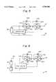
- FIGS. 4, 5, 6 and 7are circuit diagrams each showing a particular modified form of the embodiment shown in FIG. 1 or 3;
- FIG. 8is a circuit diagram showing a conventional protection circuit for comparison with the present invention.
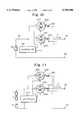
- FIG. 9is a circuit diagram showing another alternative embodiment of the present invention.
- FIGS. 10, 11, 12 and 13are circuit diagrams each showing a particular modified form of the embodiment shown in FIG. 9.
- the power source circuitis implemented as a power source unit or so-called battery pack 30 accommodating two secondary or rechargeable batteries 10 and 12 connected in series.
- a positive terminal 32 and a negative terminal 34are provided on the battery pack 30 and connected to the serial connection of the batteries 10 and 12 via a protection device 20 embodying the present invention.
- the battery pack 30is removably mounted to, e.g., a VCR with a video camera.
- the batteries 10 and 12may be comprised of, but not limited to, nickel-cadmium (Ni--Cd) batteries or nickel-hydrogen (Ni--H) batteries or, advantageously, lithium ion (Li + ) secondary batteries.
- Lithium ion batteriesfor example, have an operating voltage ranging from 2.5 V to 4.2 V each. When the lithium ion battery is charged to a terminal voltage of above 4.3 V or so, the performance of the battery is deteriorated more than by the usual cycle deterioration. When the battery is discharged to a terminal voltage of below 2.4 V or so, the above deterioration worse than the usual cycle deterioration also occurs.
- the protection device 20detects the terminal voltage of the individual battery, implemented by lithium ion battery by way of example, 10 or 12 and blocks either a charge path or a discharge path in such a manner as to prevent one of the batteries 10 and 12 from being charged to above 4.3 V or discharged to below 2.4 V. This successfully protects the batteries 10 and 12 from overcharge and overdischarge.
- the protection device 20is made up of a controller 210, a switch 220 for blocking a discharge path, a switch 230 for blocking a charge path, and diodes 240 and 250 assigned to the charge path and discharge path, respectively.
- the controller 14detects the terminal voltage of the battery 10 and that of the battery 12 independently and controls the individual battery 10 or 12 on the basis of the detected voltage.
- FIG. 2shows a specific configuration of the controller 14.
- the controller 14has a first battery voltage detector 300, a second battery voltage detector 302, a first comparator 304, a second comparator 306, a first OR gate 308, a second OR gate 310, a first switch driver 312, and a second switch driver 314.
- the first battery voltage detector 300is connected to a positive electrode 10a and a negative electrode 11 included in the battery 10 so as to detect a difference between the potentials of the electrodes 10a and 11.
- the output voltage of the voltage detector 300 representative of the differenceis applied to the comparator 304.
- the second battery voltage detector 302is connected to the positive electrode 11 and negative electrode 34 of the other battery 12, and feeds a voltage representative of a difference between the potential of the electrode 11 and that of the terminal 34 to the comparator 306.
- the potential from the negative electrode of the battery 10 and the potential from the positive electrode of the battery 12are commonly fed to the voltage detectors 300 and 302.
- the voltage detectors 300 and 302each detects a difference between the common potential and the potential from the other electrode of the respective battery 10 or 12.
- the comparator 304having one input and two outputs, determines whether or not the output voltage of the voltage detector 300 is higher than a first preselected reference voltage or lower than a second preselected reference voltage.
- the comparator 306is identical in configuration with the comparator 304 and determines whether or not the output voltage of the voltage detector 302 is higher than the first reference voltage or lower than the second reference voltage.
- the first reference voltageis selected to be close to the full-charge voltage of the battery 10 or 12; assuming the previously mentioned lithium ion battery, it ranges from about 4.2 V to about 4.3 V, but lower than 4.3 V.
- the second reference voltageis selected to be close to the full-discharge voltage of the battery 10 or 12; in the case of a lithium ion battery, it ranges from about 2.4 V, but higher than 2.4 V, to about 2.5 V.
- the full-discharge voltageis referred to the voltage developed by a battery when completely discharged.
- the comparators 304 and 306each produces a first and a second output respectively representative of the results of comparison using the first and second reference values.
- the first outputs of the comparators 304 and 30are applied to the OR gate 308 while the second outputs of the same are applied to the OR gate 310.
- the OR gate 308produces an OR of the first outputs of the comparators 304 and 306.
- the OR gate 308feeds a valid output to the switch driver 312.
- the OR gate 310ORs the second outputs of the comparators 304 and 306 to see if the output of either one of the comparators 304 and 306 is representative of a voltage lower than the second reference voltage. If the result of this decision is positive, the OR gate 310 delivers a valid output to the switch driver 314.
- the switch driver 312is a voltage generating circuit which generates a signal for selectively turning on or turning off the switch 230 in response to the logical output of the OR gate 308.
- the switch driver 314is identical with the switch driver 312 except that it generates a signal for selectively turning on or turning off the switch 220 in response to the logical output of the OR gate 310.
- the switch 230 for blocking the charge pathis a semiconductor switch implemented by, e.g., a CMOS (Complementary Metal-Oxide Semiconductor) FET operable at a low voltage.
- the switch 230normally remains turned on.
- the switch 230is turned off to shut off a current flowing in a charging direction, as indicated by an arrow Y in FIG. 1.
- the switch 230is comprised of a normally OFF P-channel enhancement type FET.
- the switch 230has a drain D connected to the positive electrode 10a of the battery 10 and has a source S connected to the input/output terminal 32.
- the control voltage from the controller 210is applied to the gate G of the switch 230.
- the FET 230involves a parasitic diode 232 due to its particular structure. When the FET 230 is turned off, the parasitic diode 232 would cause a current to flow between the source S and the drain D in the direction opposite to the blocking direction, i.e., a discharging direction X opposite to the charging direction Y.
- the switch 220 for blocking the discharge pathis also a semiconductor switch implemented by, e.g., a normally OFF P-channel enhancement type FET.
- the switch 220is connected in series between the switch 230 and the input/output terminal 32.
- the switch 220normally remains in its ON or conductive state and allows a current to flow in both the charging direction Y and the discharging direction X.
- the switch 220is turned off by a control voltage fed from the controller 210, it shuts off the current to flow in the discharging direction X.
- the switch 220has a drain D connected to the input/output terminal 32 and has a source S connected to the source S of the switch or FET 220.
- the control signal form the controller 210is applied to the gate G of the FET 220.
- the FET 220involves a parasitic diode 222 due to its particular structure. When the FET 220 is turned off, the parasitic diode 222 would allow a current to flow from the drain D to the source S of the FET 220, i.e., in the charging direction Y.
- the diode 240 assigned to the charge pathis connected in parallel with the switch 220.
- the diode 240allows a current to flow therethrough in the same direction as through the parasitic diode 222 while bypassing the diode 222, i.e., the switch 220.
- the diode 240may advantageously be implemented by a Schottky barrier diode. However, in the illustrative embodiment, the diode 240 should only be turned on at a lower voltage than the parasitic diode 222 of the FET 220 when the FET 220 is turned off.
- the Schottky barrier diodemay be replaced with, e.g., a point contact diode using germanium for a pellet.
- the diode 250 assigned to the discharge pathis connected in parallel with the switch 230. When the switch 230 is turned off, the diode 250 allows a current to flow therethrough in the same direction as through the parasitic diode 232 while bypassing the switch 230.
- the diode 250like the diode 240, may advantageously be implemented by a Schottky diode or a germanium diode.
- the battery pack 30is mounted to a VCR with a video camera or similar portable electronic apparatus, not shown, and has the terminals 32 and 34 thereof connected to circuitry built in the apparatus.
- the apparatushas, e.g., a cord thereof connected to an AC power source.
- a charge currentis fed from the AC power source to the pack 30 via a charging circuit included in the apparatus and the terminals 32 and 34 of the pack 30.
- the controller 210constantly monitors the voltages of the batteries 10 and 12.
- a negative control voltageis fed from the controller 210 to the switches 220 and 230, thereby maintaining them in an ON state.
- the charge current Yis fed from the terminal 32 to the batteries 10 and 12 via the switches 220 and 230 in the charging direction Y. Further, the charge current flows out of the pack 30 to the apparatus via the terminal 34. In this condition, the batteries 10 and 12 are each charged by the charge current.
- the fully charged battery 10 or 12reaches the upper limit of the allowable recharging condition earlier than the other battery.
- the battery 10has reached the upper limit, causing the voltage detector 300 to output a voltage of, e.g., 4.2 V.
- the comparator 304detects such a rise of the voltage and feeds a valid output to the OR gate 308.
- the voltage detector 302determines that the voltage of the other battery 12 is lower than 4.2 V, and causes the comparator 306 to feed an invalid output to the OR gate 308.
- the OR gate 308delivers a valid output to the switch driver 312 due to the valid output of the comparator 304.
- the switch driver 312feeds a positive control voltage to the gate G of the FET 230.
- the controller 210detects it and delivers a negative control voltage to the switch 230 so as to turn it on. In this condition, the discharge current is caused to flow through the switch 230 with the result that the diode 250 is rendered nonconductive.
- the controller 210delivers a negative control voltage to the switches 220 and 230 and thereby maintains them in the ON state thereof.
- a discharge currentflows from the positive electrode 10a of the battery 10 to the apparatus via the switches 230 and 220 and terminal 32. Further, the current coming in through the terminal 34 from the apparatus flows to the battery 12 in the discharging direction X.
- the battery pack 30is mounted to a VCR with a video camera, that the batteries 10 and 12 are lithium ion batteries, and that the VCR is continuously operated for more than 1 hour. Then, the voltages of the batteries 10 and 12 drop below 3.0 V each. As the operation of the VCR is further continued, one of the batteries 10 and 12 approaches the allowable limit of discharge. For example, assume that the battery 10 approaches the allowable limit of discharge and causes the voltage detector 300 to output a voltage of 2.6. Then, the comparator 304 detects the above voltage drop and delivers a valid output thereof to the OR gate 310.
- the comparator 306may deliver an invalid output to the OR gate 310
- the OR gate 310feeds a valid output to the switch driver 314 due to the valid output of the comparator 304. Consequently, the switch driver 314 delivers a positive control voltage to the gate G of the switch or FET 220.
- the positive control voltage from the switch driver 314shuts off the current between the drain D and the source S of the FET 220 and, therefore, the current from the batteries 10 and 12 flowing in the discharging direction X.
- the current in the charging direction Ytends to flow from the negative electrode 11 of the battery 10 to the terminal 34 via the battery 12, and then from the terminal 32 to the positive electrode 10a of the battery 10 via the parasitic diode 222 of the switch 220 and the switch 230 which are in an OFF or non-conductive state and an ON state, respectively.
- the diode 240is rendered conductive prior to the parasitic diode 222.
- the currentflows through the diode 240 to the battery 10, bypassing the switch 220. This prevents the parasitic diode 222 from being rendered conductive.
- the controller 210detects it and delivers a negative control voltage to the switch 220 so as to turn it on. Consequently, the charge current is caused to flow through the switch 220 while the diode 240 is rendered nonconductive.
- FIG. 8A reference will be made to FIG. 8 for describing a conventional protection device in order to clear up the advantages of the above embodiment.
- the same or similar constituents as or to the constituents shown in FIG. 1are designated by the same reference numerals, and a detailed description thereof will not be made in order to avoid redundancy.
- the conventional devicelacks the diodes 240 and 250. In operation, when a controller 210 determines that one of two batteries 10 and 12 has been fully charged, it turns off a switch 230.
- a current in a charging direction Yis shut off; a discharge current X flows to a terminal 32 via a parasitic diode 232 included in the switch 230 and a switch 220 which are in an OFF state and an ON state, respectively.
- the switch 220is turned off when the battery 10 or 12 approaches the limit of discharge. This shuts off the discharge current X and, at the same time, causes the charge current Y to flow from the terminal 32 to the batteries 10 and 12 via the parasitic diode 222 of the switch 220 and the switch 230 which are in an OFF state and an ON state, respectively.
- a currentflows through the parasitic diode 222 or 232 when the switch 220 or 230 is turned off.
- Such currentsdifferent from the expected currents, deteriorate the switching characteristic of the switches 220 and 230 and damage the switches 220 and 230 in due course of time.
- the diodes 240 and 250 connected in parallel with the switches 220 and 330, respectively,are each rendered conductive at a lower voltage than the associated parasitic diode 222 or 232, thereby forming a bypass. Therefore, when the switch 220 or 230 is turned off, the parasitic diode 222 or 232 associated therewith is free from a current otherwise flowing in the direction opposite to the blocking direction. This successfully prevents the switching characteristic from being deteriorated and the switch itself from being damaged.
- the embodimenthas another advantage over the conventional device shown in FIG. 8, as follows.
- the parasitic diode 222is rendered conductive when the batteries 10 and 12 are charged, while the parasitic diode 232 is rendered conductive when they are discharged.
- the parasitic diode of an FEThas a forward drop voltage V F which is as high as, e.g., 0.6 V to 0.7 V.
- V Fforward drop voltage
- the diodes 222 and 232 shown in FIG. 8consume power due to their high drop voltage V F .
- the batteries 10 and 12cannot be charged with a sufficient voltage while, in the event of discharging, they cannot feed power to a load with a sufficient voltage.
- the high drop voltage V Fis apt to cause the FETs 222 and 232 to generate heat.
- the diodes 240 and 250are respectively connected in parallel with and with the same polarity as the parasitic diodes 222 and 232 which have the high voltage drop V F , as mentioned above. This prevents the parasitic diodes 222 and 232 from being rendered conductive when the batteries 10 and 12 are charged or discharged.
- the diodes 240 and 250are implemented by Schottky barrier diodes or similar elements lower in forward drop voltage V f than the parasitic diode 222 and 232.
- a Schottky diodehas a forward drop voltage V F as low as about 0.4 V. Hence, the diode 240 or 250 consumes a minimum of power in the event of charging or discharging.
- the batteries 10 and 12can be charged with a sufficient voltage and can feed power to a load with a sufficient voltage.
- the FETs 222 and 232generate a minimum of heat because the parasitic diodes 222 and 232 having a high voltage drop V F are not rendered conductive. Because the parasitic diodes 222 and 232 are too unstable to be positively used, omitting them enhances the reliability of the entire pack 30 in combination with the minimum heat generation.
- FIG. 3an alternative embodiment of the present invention will be described.
- This embodimentdiffers from the embodiment shown in FIG. 1 in that the switch 230 for blocking the charge path and the diode 250 assigned to the discharge path are connected to the positive terminal 32, and in that the switch 220 for blocking the discharge path and the diode 240 assigned to the charge path are connected to the negative terminal 34.
- the switch 220is advantageously an N-channel FET.
- the same or similar constituents as or to the constituents shown in FIG. 1are designated by the same reference numerals.
- the switches 220 and 230 opposite in direction to each otherare not directly connected in series. This eliminates an occurrence that when the controller 210 turns off one of the switches 220 and 230, the resulting extremely high momentary voltage is applied to the other switch and renders the parasitic diode thereof conductive.
- the switch 230 shown in FIG. 1is turned off, the current Y flowing from the drain D to the source S of the switch 220 is blocked with the result that a discharge current opposite in direction to the above current tends to flow.
- the voltage between the drain D and the source S and tending to momentarily shut off the current in the discharge directionis apt to temporarily turn on the parasitic diode 222 which is conductive in the charging direction.
- the embodiment shown in FIG. 3reduces the influence of the operation of one of the switches 220 and 230 on the other switch due to the batteries 10 and 12 intervening between the switches 220 and 230.
- the battery pack 30is assumed to be mounted to a VCR with a video camera, it may, of course, be mounted to any other electronic apparatus.
- a lithium ion batteryis merely a specific form of a secondary or rechargeable battery with which the present invention is practicable.
- the first and second reference voltageswill, therefore, be varied in matching relation to the characteristic of the secondary battery selected.
- FETs playing the role of switching elementsmay be replaced with any other electronic switches.
- the switches 220 and 230 and their associated diodes 240 and 250are connected to the positive terminal 32.
- the switches 220 and 230 and diodes 240 and 250may be connected to the negative terminal 34.
- both of the switches 220 and 230are advantageously N-channel FETs.
- the present inventionis, of course, practicable even with a single battery, as shown in FIG. 5.
- While the embodiments shown and describeddetect the terminal voltage of each the batteries 10 and 12, an arrangement may be so made as to detect voltages appearing on the opposite ends of the serial connection of the batteries 10 and 12, as shown in FIG. 6.
- the present inventionis effective even when N (3 or greater natural number) batteries are connected in series, as shown in FIG. 7.
- the embodiments shown and describedeach has switches and diodes respectively connected in parallel with the switches and each being identical in direction with a parasitic diode included in the associated switch.
- a currentflows through the diode connected to the switch prior to the parasitic diode of the switch. This prevents a current from flowing through the switch in the opposite direction.
- the switchesare, therefore, free from deterioration and damage and allow the protection device to surely operate without being damaged.
- FIG. 9shows another alternative embodiment of the protection device in accordance with the present invention.
- the protection device 20has the switch 230 for blocking a charge path, switch 220 for blocking a discharge path, and diodes 240 and 250 assigned to the charge path and discharge path, respectively.
- the switch 230is implemented by a CMOS FET or similar semiconductor switch operable at a low voltage.
- the switch 230 and diode 240form the charge path in combination.
- the switch 230is advantageously comprised of a normally OFF P-channel enhancement type FET which remains in an ON state in response to a negative voltage.
- the switch 230usually remains in an ON state to allow a current in a charging direction Y to flow therethrough.
- the switch 230On receiving a positive control voltage from the controller 210, the switch 230 is turned off to thereby shut off the current in the charging direction Y.
- the switch or FET 230has a drain D connected to the positive electrode 10a of the battery 10 and has a source S connected to the input/output terminal 32 via the diode 240.
- the control voltage from the controller 210is applied to the gate G of the switch 230.
- a parasitic diode 232is included in the FET 230 due to the particular structure of the FET 230. When the FET 230 is turned off, the parasitic diode 232 would cause a current to flow between the source S and the drain D in a direction opposite to the blocking direction, i.e., in a discharging direction.
- the switch 220is also a semiconductor switch implemented by, e.g., a normally OFF P-channel enhancement type FET.
- the switch 220 and diode 250form the discharge path in combination.
- the switch 220is parallel to the charge path, i.e., the serial connection of the switch 230 and diode 240, but opposite in direction to the switch 230.
- the switch 220remains in an ON state and allows a current to flow in a discharging direction X. When the switch 220 is turned off, it blocks the current in the discharging direction X.
- the switch 220has a source S connected to the positive electrode 10a of the battery 10 and a drain D connected to the input/output terminal 32.
- the control signal from the controller 210is applied to the gate G of the FET 220.
- a parasitic diode 222is included in the FET 220 due to the particular structure of the FET 220. The parasitic diode 222 functions such that when the FET 220 is in an OFF state, a current would flow from the drain D to the source S, i.e., in the charging direction.
- the diode 240is serially connected to the switch 230 which functions to block the charge path.
- the diode 240allows a current to flow therethrough in the charging direction Y when turned on, or shuts it off when turned off.
- the diode 240may advantageously be implemented by, e.g., a Schottky barrier diode, germanium diode, or silicon diode.
- the diode 240prevents a current from flowing through the parasitic diode 232.
- the diode 250is serially connected to the switch 220. The diode 250 allows a current to flow therethrough in the discharging direction X when turned on, or shuts it off when turned off so as to prevent a current from flowing through the parasitic diode 222.
- the power source unit or battery pack 30is mounted to a portable electronic apparatus, not shown, and has the terminals 32 and 34 thereof connected to circuitry built in the apparatus.
- the apparatushas, e.g., a cord thereof connected to an AC power source.
- a charge currentis fed from the AC power source to the pack 30 via a charging circuit included in the apparatus and the terminals 32 and 34 of the pack 30.
- the controller 210constantly monitors the voltages of the batteries 10 and 12. If the voltages of the batteries 10 and 12 lie in the previously stated range, a negative control voltage is fed from the controller 210 to the switches 230 and 220, thereby maintaining them in an ON state.
- the charge currentis fed from the terminal 32 to the batteries 10 and 12 via the diode 240 and switch 230 in the charging direction Y. Further, the charge current flows out of the pack 30 to the apparatus via the terminal 34 in the charging direction Y. In this condition, the batteries 10 and 12 are each charged by the charge current.
- the fully charged battery 10 or 12reaches the upper limit of the allowable recharging condition earlier than the other battery.
- the controller 210feeds a positive control voltage to the gate G of the FET 230.
- the current between the drain D and the source D of the FET 230 and, therefore, the current coming in through the terminal 32 in the charging direction Yis shut off. This prevents the battery 10 from being overcharged.
- the discharge currentflows from the positive electrode 10a of the battery 10 to the terminal 32 via the switch 220 which is in an ON state and the diode 250, and from the terminal 32 to the apparatus.
- a current in the discharging direction Xtends to flow through the parasitic diode 232 of the switch 230.
- the current from the parasitic diode 232is blocked because the diode 240 serially connected to the switch 230 is opposite in direction to the diode 232.
- the FET 230blocks the charge current due to the rise of the voltage of the battery 10 to the upper limit, the voltage of the battery 10 begins to drop due to the impedance inside of the battery 10 or the leveling of ion density inside of the battery 10.
- the controller 210detects it and delivers a negative control voltage to the switch 230.
- the switch 230is turned on and allows the batteries 10 and 12 to be again charged via the diode 240.
- the controller 210delivers a negative control voltage to the switches 220 and 230 and thereby maintains them in an ON state.
- a discharge currentflows from the positive electrode 10a of the battery 10 to the apparatus via the switch 220, diode 250, and terminal 32. Further, the current coming in through the terminal 34 from the apparatus flows to the battery 12 in the discharging direction. In this condition, the batteries 10 and 12 are sequentially discharged.
- the battery pack 30is mounted to a VCR with a video camera, that the batteries 10 and 12 are lithium ion batteries, and that the VCR is continuously operated for more than 1 hour. Then, the voltages of the batteries 10 and 12 drop below 3.0 V each. As the operation of the VCR is further continued, one of the batteries 10 and 12 approaches the allowable limit of discharge. For example, when the battery 10 approaches the allowable limit of discharge and causes a voltage 2.4 V to 2.5 V to appear on the positive electrode 10a, the controller 210 feeds a positive control voltage to the gate G of the FET 220.
- the controller 210detects it and delivers a negative control voltage to the switch 220.
- the control voltageturns on the switch 220 and thereby sets up a dischargeable state, i.e., prevents overcharge from occurring.
- the diodes 250 and 240are respectively connected to the switches 220 and 230 in series, and each allows a current to pass therethrough only in one direction.
- the serial connections of the diodes 250 and 240 and switches 220 and 230are parallel to each other. In this configuration, when one of the switches 220 and 230 is turned off, a current opposite in direction to the blocking direction of the switch 220 or 230 is prevented from flowing through the associated diode 222 or 232.
- Thissuccessfully protects the switching characteristic of the switches 222 and 232 from deterioration and thereby protects the switches 222 and 232 from damage.
- the embodimentmay be modified to detect the voltage of each of N (3 or greater natural number) batteries and controls the switch 220 or 230 on determining that any one of such voltages has risen above the upper limit or has dropped below the lower limit.
- the switches 220 and 230 and their associated diodes 250 and 240are shown as being connected to the positive terminal 32.
- the switches 220 and 230 and diodes 240 and 250may be connected to the negative terminal 34.
- a charge path and a discharge pathare connected in parallel with each other, and each has a serial connection of a switch and a diode opposite in direction to a parasitic diode included in the switch.
Landscapes
- Engineering & Computer Science (AREA)
- Chemical & Material Sciences (AREA)
- Chemical Kinetics & Catalysis (AREA)
- Electrochemistry (AREA)
- General Chemical & Material Sciences (AREA)
- Manufacturing & Machinery (AREA)
- Microelectronics & Electronic Packaging (AREA)
- Power Engineering (AREA)
- Charge And Discharge Circuits For Batteries Or The Like (AREA)
Abstract
Description
1. Field of the Invention
The present invention relates to a device for protecting a secondary battery from overcharge and overdischarge and, more particularly, to a device applicable to a power source unit removably mounted to a portable electronic apparatus in order to protect a secondary battery accommodated in the unit from overcharge and overdischarge.
2. Description of the Background Art
Today, various kinds of electronic apparatuses including a video cassette recorder (VCR) with a video camera, personal computer and telephone set are available with a miniature portable configuration. Most of the portable apparatuses are powered by a primary battery or a secondary battery. A secondary battery is predominant over a primary battery because it is rechargeable. The prerequisite with a power source unit implemented by a secondary battery is that it be surely protected from overcharge and overdischarge. Overcharge or overdischarge would decompose substances sealed in the secondary battery and would thereby lower the capacity of the battery. If the battery is repeatedly overcharged or overdischarged, the decrease in battery capacity is accelerated until the service life of the battery expires.
For the protection of the secondary battery from overcharge and overdischarge, it has been customary to monitor the voltage of the battery and selectively block a charge path or a discharge path. Specifically, when the battery voltage rises above a reference voltage during the course of charging, the charge path is blocked off. When the battery voltage drops below another reference voltage, the discharge path is blocked off. Japanese utility model laid-open publication No. 136445/1990, for example, teaches a protection circuit for a serial connection of a plurality of secondary or rechargeable batteries. The protection circuit, monitoring the voltage of the individual battery, blocks a charge path or a discharge path when the voltage of any one of the batteries rises above a reference voltage or drops below another reference voltage.
It is a common practice to block the charge and discharge circuits by use of semiconductor switches which are desirable from the cost and size standpoint. For example, Japanese patent laid-open publication Nos. 33271/1992, 75430/1992, and 75431/1992 each proposes a power source unit using a secondary battery, and switches implemented by FETs (Field Effect Transistors) each inherently involving a parasitic diode. Among them, the unit taught in laid-open publication No. 75430/1992 has a serial connection of first and second FETs connected to one electrode of a secondary battery. The first and second FETs are used to block a charge path and a discharge path, respectively. In this configuration, the first FET is turned on to unblock the charge path when the voltage between the opposite electrodes of the battery drops below a first voltage close to a chargeable voltage, or turned off to block it when the voltage rises to a second voltage higher than the first voltage. The second FET is turned on to unblock the discharge path when the battery voltage rises to a third voltage close to a dischargeable voltage, or turned off to block it when the battery voltage drops below a fourth voltage lower than the third voltage. When the charge path is blocked against overcharge, the parasitic diode of the first FET which becomes conductive in the opposite direction to the charging direction forms a discharge path. Also, when the discharge path is blocked against overdischarge, the parasitic diode of the second FET forms a charge path because it becomes conductive in the opposite direction to the discharging direction. Specifically, because an FET involves, due to its particular structure, a parasitic diode which allows a current to flow therethrough in the direction opposite to the blocking direction, the blocking effect available with the FET is only one-way. The above laid-open publication No. 75431/1992 positively uses this phenomenon and connects two FETs in series, but in opposite directions to each other. This kind of scheme secures a discharge path in the event of overcharge protection and secures a charge path in the event of overdischarge protection, while obviating overcharge and overdischarge.
However, when the charge path and discharge path are secured by making the most of the parasitic diodes included in the FETs, but not intended for use due to the particular structure, the FETs or switches are easy to deteriorate. This lowers the switching function of the FETs and damages the FETs in due course of time. When the switching function is lowered, the FETs fail to block the charge path or the discharge path at an adequate time. Should the FETs be continuously used in such a condition, the secondary battery would be overcharged or overdischarged, resulting in the previously stated troubles.
It is, therefore, an object of the present invention to provide a device capable of surely protecting a secondary battery from overcharge and overdischarge by obviating the deterioration and damage of switching elements.
In accordance with the present invention, a device for protecting a rechargeable secondary battery from overcharge and overdischarge has a first normally ON switch serially connected to the charge/discharge path of the secondary battery. The first switch causes a current to flow in a charging direction when turned on or blocks the charge/discharge path in the charging direction when turned off. The first switch includes a parasitic diode which is rendered conductive in a discharging direction when the first switch is turned off. A second normally ON switch is also serially connected to the charge/discharge path. The second switch causes a current to flow in the discharging direction when turned on or blocks the charge/discharge path in the discharging direction when turned off. The second switch includes a parasitic diode which is rendered conductive in the charging direction when the second switch is turned off. A controller detects the voltage of the secondary battery. The controller turns off the first switch when the voltage of the secondary battery rises above a first reference voltage higher than a predetermined voltage close to a full-charge voltage or turns off the second switch when the voltage drops below a second reference voltage lower than a predetermined voltage close to a full-discharge voltage. A first diode is connected in parallel with the first switch and conductive in the same direction as the parasitic diode of the first switch to thereby form a bypass for causing a current in the discharging direction to bypass the first switch. A second diode is connected in parallel with the second switch and conductive in the same direction as the parasitic diode of the second switch to thereby form a bypass for causing a current in the charging direction to bypass the second switch.
Also, in accordance with the present invention, a device for protecting a rechargeable secondary battery from overcharge and overdischarge has a first normally ON switch connected to the charge path of the secondary battery. The first switch causes a current to flow in a charging direction when turned on or blocks the charge path in the charging direction when turned off. The first switch includes a parasitic diode which is rendered conductive in a discharging direction when the first switch is turned off. A second normally ON switch is connected to the discharge path of the secondary battery. The second switch causes a current to flow in the discharging direction when turned on or blocks the discharge path in the discharging direction when turned off. The second switch includes a parasitic diode which is rendered conductive in the charging direction when the second switch is turned off. A controller detects the voltage of the secondary battery. The controller turns off the first switch when the voltage of the secondary battery rises above a first reference voltage higher than a predetermined voltage close to a full-charge voltage or turns off the second switch when the voltage drops below a second reference voltage lower than a predetermined voltage close to a full-discharge voltage. The charge path and discharge path branch, in parallel, from between the secondary battery and one of the input/output terminals of the paths. A first diode is serially connected to the first switch in a direction opposite to the parasitic diode of the first switch with respect to conduction. A second diode is serially connected to the second switch in a direction opposite to the parasitic diode of the second switch with respect to conduction.
The objects and features of the present invention will become more apparent from the consideration of the following detailed description taken in conjunction with the accompanying drawings in which:
FIG. 1 is a circuit diagram showing a power source unit to which a protection device embodying the present invention is applied;
FIG. 2 is a schematic block diagram showing a specific construction of a controller included in the embodiment;
FIG. 3 is a circuit diagram showing an alternative embodiment of the present invention;
FIGS. 4, 5, 6 and 7 are circuit diagrams each showing a particular modified form of the embodiment shown in FIG. 1 or 3;
FIG. 8 is a circuit diagram showing a conventional protection circuit for comparison with the present invention;
FIG. 9 is a circuit diagram showing another alternative embodiment of the present invention; and
FIGS. 10, 11, 12 and 13 are circuit diagrams each showing a particular modified form of the embodiment shown in FIG. 9.
Referring to FIG. 1 of the drawings, a power source circuit to which a protection circuit embodying the present invention is applied is shown. As shown, the power source circuit is implemented as a power source unit or so-calledbattery pack 30 accommodating two secondary orrechargeable batteries positive terminal 32 and anegative terminal 34 are provided on thebattery pack 30 and connected to the serial connection of thebatteries protection device 20 embodying the present invention. Thebattery pack 30 is removably mounted to, e.g., a VCR with a video camera.
Thebatteries protection device 20 detects the terminal voltage of the individual battery, implemented by lithium ion battery by way of example, 10 or 12 and blocks either a charge path or a discharge path in such a manner as to prevent one of thebatteries batteries
Specifically, as shown in FIG. 1, theprotection device 20 is made up of acontroller 210, aswitch 220 for blocking a discharge path, aswitch 230 for blocking a charge path, anddiodes battery 10 and that of thebattery 12 independently and controls theindividual battery
FIG. 2 shows a specific configuration of the controller 14. As shown, the controller 14 has a firstbattery voltage detector 300, a secondbattery voltage detector 302, afirst comparator 304, asecond comparator 306, a first ORgate 308, a second ORgate 310, afirst switch driver 312, and asecond switch driver 314. The firstbattery voltage detector 300 is connected to apositive electrode 10a and anegative electrode 11 included in thebattery 10 so as to detect a difference between the potentials of theelectrodes voltage detector 300 representative of the difference is applied to thecomparator 304. Likewise, the secondbattery voltage detector 302 is connected to thepositive electrode 11 andnegative electrode 34 of theother battery 12, and feeds a voltage representative of a difference between the potential of theelectrode 11 and that of the terminal 34 to thecomparator 306. As shown in FIG. 1, the potential from the negative electrode of thebattery 10 and the potential from the positive electrode of thebattery 12 are commonly fed to thevoltage detectors voltage detectors respective battery
Thecomparator 304, having one input and two outputs, determines whether or not the output voltage of thevoltage detector 300 is higher than a first preselected reference voltage or lower than a second preselected reference voltage. Thecomparator 306 is identical in configuration with thecomparator 304 and determines whether or not the output voltage of thevoltage detector 302 is higher than the first reference voltage or lower than the second reference voltage. For each of thecomparators battery battery comparators comparators OR gate 308 while the second outputs of the same are applied to theOR gate 310.
The ORgate 308 produces an OR of the first outputs of thecomparators comparators OR gate 308 feeds a valid output to theswitch driver 312. Likewise, theOR gate 310 ORs the second outputs of thecomparators comparators OR gate 310 delivers a valid output to theswitch driver 314.
Theswitch driver 312 is a voltage generating circuit which generates a signal for selectively turning on or turning off theswitch 230 in response to the logical output of theOR gate 308. Theswitch driver 314 is identical with theswitch driver 312 except that it generates a signal for selectively turning on or turning off theswitch 220 in response to the logical output of theOR gate 310.
Referring again to FIG. 1, theswitch 230 for blocking the charge path is a semiconductor switch implemented by, e.g., a CMOS (Complementary Metal-Oxide Semiconductor) FET operable at a low voltage. Theswitch 230 normally remains turned on. In response to a control voltage output from thecontroller 210, theswitch 230 is turned off to shut off a current flowing in a charging direction, as indicated by an arrow Y in FIG. 1. Advantageously, theswitch 230 is comprised of a normally OFF P-channel enhancement type FET. Theswitch 230 has a drain D connected to thepositive electrode 10a of thebattery 10 and has a source S connected to the input/output terminal 32. The control voltage from thecontroller 210 is applied to the gate G of theswitch 230. TheFET 230 involves aparasitic diode 232 due to its particular structure. When theFET 230 is turned off, theparasitic diode 232 would cause a current to flow between the source S and the drain D in the direction opposite to the blocking direction, i.e., a discharging direction X opposite to the charging direction Y.
Theswitch 220 for blocking the discharge path is also a semiconductor switch implemented by, e.g., a normally OFF P-channel enhancement type FET. Theswitch 220 is connected in series between theswitch 230 and the input/output terminal 32. Theswitch 220 normally remains in its ON or conductive state and allows a current to flow in both the charging direction Y and the discharging direction X. When theswitch 220 is turned off by a control voltage fed from thecontroller 210, it shuts off the current to flow in the discharging direction X. Specifically, theswitch 220 has a drain D connected to the input/output terminal 32 and has a source S connected to the source S of the switch orFET 220. The control signal form thecontroller 210 is applied to the gate G of theFET 220. TheFET 220 involves aparasitic diode 222 due to its particular structure. When theFET 220 is turned off, theparasitic diode 222 would allow a current to flow from the drain D to the source S of theFET 220, i.e., in the charging direction Y.
Thediode 240 assigned to the charge path is connected in parallel with theswitch 220. When theswitch 220 is turned off, thediode 240 allows a current to flow therethrough in the same direction as through theparasitic diode 222 while bypassing thediode 222, i.e., theswitch 220. Thediode 240 may advantageously be implemented by a Schottky barrier diode. However, in the illustrative embodiment, thediode 240 should only be turned on at a lower voltage than theparasitic diode 222 of theFET 220 when theFET 220 is turned off. In this sense, the Schottky barrier diode may be replaced with, e.g., a point contact diode using germanium for a pellet. On the other hand, thediode 250 assigned to the discharge path is connected in parallel with theswitch 230. When theswitch 230 is turned off, thediode 250 allows a current to flow therethrough in the same direction as through theparasitic diode 232 while bypassing theswitch 230. Thediode 250, like thediode 240, may advantageously be implemented by a Schottky diode or a germanium diode.
The operation of the illustrative embodiment will be described hereinafter. Assume that thebattery pack 30 is mounted to a VCR with a video camera or similar portable electronic apparatus, not shown, and has theterminals batteries pack 30 via a charging circuit included in the apparatus and theterminals pack 30. Specifically, thecontroller 210 constantly monitors the voltages of thebatteries batteries controller 210 to theswitches batteries switches pack 30 to the apparatus via theterminal 34. In this condition, thebatteries
Assume that either thebattery 10 or thebattery 12 fully charged by the above current is further charged. Then, the fully chargedbattery battery 10 has reached the upper limit, causing thevoltage detector 300 to output a voltage of, e.g., 4.2 V. Then, thecomparator 304 detects such a rise of the voltage and feeds a valid output to theOR gate 308. At this instant, assume that thevoltage detector 302 determines that the voltage of theother battery 12 is lower than 4.2 V, and causes thecomparator 306 to feed an invalid output to theOR gate 308. However, theOR gate 308 delivers a valid output to theswitch driver 312 due to the valid output of thecomparator 304. In response, theswitch driver 312 feeds a positive control voltage to the gate G of theFET 230.
Consequently, the current between the source S and the drain D of theFET 230 and, therefore, the current coming in through the terminal 32 in the charging direction Y is blocked. This prevents thebattery 10 from being overcharged. When thepack 30 in this condition is used, a discharge current tends to flow from thepositive electrode 10a of thebattery 10 in the direction in which theparasitic diode 232 of theswitch 230 is conductive. However, because the conduction voltage of thediode 250 connected in series with theswitch 230 is lower than the conduction voltage of theparasitic diode 232, thediode 250 is rendered conductive prior to thediode 232. As a result, the discharge current flows to the terminal 32 via thediode 250 and switch 220, bypassing theswitch 230. This successfully prevents theparasitic diode 232 from being rendered conductive.
Subsequently, when the voltage of thebattery 10 drops below 4.2 V, thecontroller 210 detects it and delivers a negative control voltage to theswitch 230 so as to turn it on. In this condition, the discharge current is caused to flow through theswitch 230 with the result that thediode 250 is rendered nonconductive.
Assume that the operator of the electronic apparatus turns on a power switch provided on the apparatus with the intention of using it. Then, thebatteries protection device 20. If the output voltages of thebatteries controller 210 delivers a negative control voltage to theswitches positive electrode 10a of thebattery 10 to the apparatus via theswitches battery 12 in the discharging direction X.
In the above condition, assume that thebattery pack 30 is mounted to a VCR with a video camera, that thebatteries batteries batteries battery 10 approaches the allowable limit of discharge and causes thevoltage detector 300 to output a voltage of 2.6. Then, thecomparator 304 detects the above voltage drop and delivers a valid output thereof to theOR gate 310. At this instant, although the voltage of thebattery 12 may not have dropped to, e.g., 2.6, as determined by thevoltage detector 302, and thecomparator 306 may deliver an invalid output to theOR gate 310, theOR gate 310 feeds a valid output to theswitch driver 314 due to the valid output of thecomparator 304. Consequently, theswitch driver 314 delivers a positive control voltage to the gate G of the switch orFET 220.
The positive control voltage from theswitch driver 314 shuts off the current between the drain D and the source S of theFET 220 and, therefore, the current from thebatteries pack 30 brought to this condition is charged via the VCR, the current in the charging direction Y tends to flow from thenegative electrode 11 of thebattery 10 to the terminal 34 via thebattery 12, and then from the terminal 32 to thepositive electrode 10a of thebattery 10 via theparasitic diode 222 of theswitch 220 and theswitch 230 which are in an OFF or non-conductive state and an ON state, respectively. However, because the conduction voltage of thediode 240 connected in parallel with theswitch 220 is lower than the conduction voltage of theparasitic diode 222, thediode 240 is rendered conductive prior to theparasitic diode 222. As a result, the current flows through thediode 240 to thebattery 10, bypassing theswitch 220. This prevents theparasitic diode 222 from being rendered conductive. When the voltage of thebattery 10 being charged rises above 2.6, thecontroller 210 detects it and delivers a negative control voltage to theswitch 220 so as to turn it on. Consequently, the charge current is caused to flow through theswitch 220 while thediode 240 is rendered nonconductive.
A reference will be made to FIG. 8 for describing a conventional protection device in order to clear up the advantages of the above embodiment. In FIG. 8, the same or similar constituents as or to the constituents shown in FIG. 1 are designated by the same reference numerals, and a detailed description thereof will not be made in order to avoid redundancy. As shown, the conventional device lacks thediodes controller 210 determines that one of twobatteries switch 230. As a result, a current in a charging direction Y is shut off; a discharge current X flows to a terminal 32 via aparasitic diode 232 included in theswitch 230 and aswitch 220 which are in an OFF state and an ON state, respectively. In the event of discharge, theswitch 220 is turned off when thebattery batteries parasitic diode 222 of theswitch 220 and theswitch 230 which are in an OFF state and an ON state, respectively. In this manner, a current flows through theparasitic diode switch switches switches
By contrast, in the illustrative embodiment, thediodes switches 220 and 330, respectively, are each rendered conductive at a lower voltage than the associatedparasitic diode switch parasitic diode
The embodiment has another advantage over the conventional device shown in FIG. 8, as follows. In FIG. 8, theparasitic diode 222 is rendered conductive when thebatteries parasitic diode 232 is rendered conductive when they are discharged. Generally, the parasitic diode of an FET has a forward drop voltage VF which is as high as, e.g., 0.6 V to 0.7 V. As a result, thediodes batteries FETs
In the illustrative embodiment, thediodes parasitic diodes parasitic diodes batteries diodes parasitic diode diode batteries FETs parasitic diodes parasitic diodes entire pack 30 in combination with the minimum heat generation.
Referring to FIG. 3, an alternative embodiment of the present invention will be described. This embodiment differs from the embodiment shown in FIG. 1 in that theswitch 230 for blocking the charge path and thediode 250 assigned to the discharge path are connected to thepositive terminal 32, and in that theswitch 220 for blocking the discharge path and thediode 240 assigned to the charge path are connected to thenegative terminal 34. With that alternative embodiment, theswitch 220 is advantageously an N-channel FET. In FIG. 3 and successive figures, the same or similar constituents as or to the constituents shown in FIG. 1 are designated by the same reference numerals.
As shown in FIG. 3, theswitches controller 210 turns off one of theswitches switch 230 shown in FIG. 1 is turned off, the current Y flowing from the drain D to the source S of theswitch 220 is blocked with the result that a discharge current opposite in direction to the above current tends to flow. At this time, the voltage between the drain D and the source S and tending to momentarily shut off the current in the discharge direction is apt to temporarily turn on theparasitic diode 222 which is conductive in the charging direction. This brings about a problem that when one of theswitches switches batteries switches
While in the above embodiments thebattery pack 30 is assumed to be mounted to a VCR with a video camera, it may, of course, be mounted to any other electronic apparatus. A lithium ion battery is merely a specific form of a secondary or rechargeable battery with which the present invention is practicable. The first and second reference voltages will, therefore, be varied in matching relation to the characteristic of the secondary battery selected. Further, FETs playing the role of switching elements may be replaced with any other electronic switches.
In the embodiment shown in FIG. 1, theswitches diodes positive terminal 32. Alternatively, as shown in FIG. 4, theswitches diodes negative terminal 34. With the latter embodiment, both of theswitches
While the embodiments shown and described detect the terminal voltage of each thebatteries batteries
As stated above, the embodiments shown and described each has switches and diodes respectively connected in parallel with the switches and each being identical in direction with a parasitic diode included in the associated switch. Hence, when one of the switches is turned off, a current flows through the diode connected to the switch prior to the parasitic diode of the switch. This prevents a current from flowing through the switch in the opposite direction. The switches are, therefore, free from deterioration and damage and allow the protection device to surely operate without being damaged.
FIG. 9 shows another alternative embodiment of the protection device in accordance with the present invention. As shown, theprotection device 20 has theswitch 230 for blocking a charge path, switch 220 for blocking a discharge path, anddiodes switch 230 is implemented by a CMOS FET or similar semiconductor switch operable at a low voltage. Theswitch 230 anddiode 240 form the charge path in combination. Theswitch 230 is advantageously comprised of a normally OFF P-channel enhancement type FET which remains in an ON state in response to a negative voltage. Theswitch 230 usually remains in an ON state to allow a current in a charging direction Y to flow therethrough. On receiving a positive control voltage from thecontroller 210, theswitch 230 is turned off to thereby shut off the current in the charging direction Y. Specifically, as shown in FIG. 9, the switch orFET 230 has a drain D connected to thepositive electrode 10a of thebattery 10 and has a source S connected to the input/output terminal 32 via thediode 240. The control voltage from thecontroller 210 is applied to the gate G of theswitch 230. Aparasitic diode 232 is included in theFET 230 due to the particular structure of theFET 230. When theFET 230 is turned off, theparasitic diode 232 would cause a current to flow between the source S and the drain D in a direction opposite to the blocking direction, i.e., in a discharging direction.
Theswitch 220 is also a semiconductor switch implemented by, e.g., a normally OFF P-channel enhancement type FET. Theswitch 220 anddiode 250 form the discharge path in combination. Theswitch 220 is parallel to the charge path, i.e., the serial connection of theswitch 230 anddiode 240, but opposite in direction to theswitch 230. Usually, theswitch 220 remains in an ON state and allows a current to flow in a discharging direction X. When theswitch 220 is turned off, it blocks the current in the discharging direction X. Specifically, theswitch 220 has a source S connected to thepositive electrode 10a of thebattery 10 and a drain D connected to the input/output terminal 32. The control signal from thecontroller 210 is applied to the gate G of theFET 220. Aparasitic diode 222 is included in theFET 220 due to the particular structure of theFET 220. Theparasitic diode 222 functions such that when theFET 220 is in an OFF state, a current would flow from the drain D to the source S, i.e., in the charging direction.
On the other hand, thediode 240 is serially connected to theswitch 230 which functions to block the charge path. Thediode 240 allows a current to flow therethrough in the charging direction Y when turned on, or shuts it off when turned off. Thediode 240 may advantageously be implemented by, e.g., a Schottky barrier diode, germanium diode, or silicon diode. On the turn-off of theswitch 230, thediode 240 prevents a current from flowing through theparasitic diode 232. Likewise, thediode 250 is serially connected to theswitch 220. Thediode 250 allows a current to flow therethrough in the discharging direction X when turned on, or shuts it off when turned off so as to prevent a current from flowing through theparasitic diode 222.
The operation of this embodiment will be described hereinafter. Assume that the power source unit orbattery pack 30 is mounted to a portable electronic apparatus, not shown, and has theterminals batteries pack 30 via a charging circuit included in the apparatus and theterminals pack 30. Specifically, thecontroller 210 constantly monitors the voltages of thebatteries batteries controller 210 to theswitches batteries diode 240 and switch 230 in the charging direction Y. Further, the charge current flows out of thepack 30 to the apparatus via the terminal 34 in the charging direction Y. In this condition, thebatteries
Assume that either thebattery 10 or thebattery 12 fully charged by the above current is further charged. Then, the fully chargedbattery battery 10 reaches the upper limit, i.e., thepositive electrode 10a thereof reaches, e.g., 4.2 V to 4.3 V, thecontroller 210 feeds a positive control voltage to the gate G of theFET 230. In response, the current between the drain D and the source D of theFET 230 and, therefore, the current coming in through the terminal 32 in the charging direction Y is shut off. This prevents thebattery 10 from being overcharged. When the apparatus with thepack 30 is operated, the discharge current flows from thepositive electrode 10a of thebattery 10 to the terminal 32 via theswitch 220 which is in an ON state and thediode 250, and from the terminal 32 to the apparatus. At this instant, a current in the discharging direction X tends to flow through theparasitic diode 232 of theswitch 230. However, the current from theparasitic diode 232 is blocked because thediode 240 serially connected to theswitch 230 is opposite in direction to thediode 232.
When theFET 230 blocks the charge current due to the rise of the voltage of thebattery 10 to the upper limit, the voltage of thebattery 10 begins to drop due to the impedance inside of thebattery 10 or the leveling of ion density inside of thebattery 10. When the voltage of thebattery 10 drops below 4.2 V, thecontroller 210 detects it and delivers a negative control voltage to theswitch 230. As a result, theswitch 230 is turned on and allows thebatteries diode 240.
Assume that a power switch provided on the electronic apparatus is turned on in order to operate the apparatus. Then, thebatteries protection device 20. If the output voltages of thebatteries controller 210 delivers a negative control voltage to theswitches positive electrode 10a of thebattery 10 to the apparatus via theswitch 220,diode 250, andterminal 32. Further, the current coming in through the terminal 34 from the apparatus flows to thebattery 12 in the discharging direction. In this condition, thebatteries
In the above condition, assume that thebattery pack 30 is mounted to a VCR with a video camera, that thebatteries batteries batteries battery 10 approaches the allowable limit of discharge and causes a voltage 2.4 V to 2.5 V to appear on thepositive electrode 10a, thecontroller 210 feeds a positive control voltage to the gate G of theFET 220. As a result, the current between the drain D and the source S of thePET 220 and, therefore, the current flowing from thebatteries pack 30 in the above condition is charged, a current in the charging direction flows from thenegative electrode 10a of thebattery 10 to the terminal 34 via thebattery 12 and then from the terminal 32 to thepositive electrode 10 via thediode 240 and switch 230 which is in an ON state. At this instant, the current in the charging direction Y also tends to flow through theparasitic diode 222 of theswitch 220. However, because thediode 250 serially connected to theparasitic diode 222 is opposite in direction to thediode 222, the above current tending to flow through thediode 222 is blocked. Subsequently, when the voltage of thebattery 10 exceeds 2.4 V, thecontroller 210 detects it and delivers a negative control voltage to theswitch 220. The control voltage turns on theswitch 220 and thereby sets up a dischargeable state, i.e., prevents overcharge from occurring.
In the above embodiment, thediodes switches diodes switches switches switch diode switches switches parasitic diodes
While the above embodiment has been shown and described in relation to twobatteries batteries batteries
Further, as shown in FIG. 12, the embodiment may be modified to detect the voltage of each of N (3 or greater natural number) batteries and controls theswitch switches diodes positive terminal 32. Alternatively, as shown in FIG. 13, theswitches diodes negative terminal 34.
In summary, in the above illustrative embodiment, a charge path and a discharge path are connected in parallel with each other, and each has a serial connection of a switch and a diode opposite in direction to a parasitic diode included in the switch. Hence, when one of the switches assigned to the respective paths is turned off, a current flows through the other path prior to the parasitic diode of the switch turned off, i.e., a current is prevented from flowing through the switch in the opposite direction. This protects the switches and, therefore, the battery pack from deterioration and damage and thereby promotes safety charging and discharging. In addition, there can be obviated the power consumption of the parasitic diodes as well as the generation of heat and the fall of reliability attributable thereto.
While the present invention has been described with reference to the particular illustrative embodiments, it is not to be restricted by the embodiments. It is to be appreciated that those skilled in the art can change or modify the embodiments without departing from the scope and spirit of the present invention.
Claims (14)
1. A device for protecting a rechargeable secondary battery from overcharge and overdischarge, comprising:
first normally ON switching means serially connected to a charge/discharge path of the secondary battery, and for causing a current to flow in a charging direction when turned on or blocking said charge/discharge path in the charging direction when turned off, said first switching means including a parasitic diode having a polarity so as to permit conduction in a discharging direction when said first switching means is turned off;
second normally ON switching means serially connected to a charge/discharge path of the secondary battery, and for causing a current to flow in the discharging direction when turned on or blocking said charge/discharge path in the discharging direction when turned off, said second switching means including a parasitic diode having a polarity so as to permit conduction in a charging direction when said second switching means is turned off;
control means for detecting a voltage of the secondary battery, and turning off said first switching means when said voltage of the secondary battery rises above a first reference voltage higher than a predetermined voltage close to a full-charge voltage or turning off said second switching means when said voltage of the secondary battery drops below a second reference voltage lower than a predetermined voltage close to a full-discharge voltage;
a first diode connected in parallel with said first switching means and conductive in a same direction as said parasitic diode of said first switching means wherein said first diode is a bypass for causing a current in the discharging direction to bypass said first switching means; and
a second diode connected in parallel with said second switching means and conductive in a same direction as said parasitic diode of said second switching means wherein said first diode is a bypass for causing a current in the charging direction to bypass said second switching means.
2. A device in accordance with claim 1, wherein said first switching means and said second switching means each comprises a semiconductor switch while said first diode and said second diode each comprises a semiconductor device which is rendered conductive at a lower voltage than said parasitic diode of the respective switching means.
3. A device in accordance with claim 2, wherein said first switching means and said second switching means each comprises an FET (Field Effect Transistor) while said first diode and said second diode each comprises a Schottky barrier diode.
4. A device in accordance with claim 2, wherein said first switching means and said second switching means each comprises an FET while said first diode and said second diode each comprises a germanium diode.
5. A device in accordance with claim 1, wherein the secondary battery comprises a serial connection of a plurality of secondary batteries, and wherein said control means, monitoring respective voltages across each of the individual secondary batteries, turns off said first switching means when the respective voltage across any one of said plurality of secondary batteries rises above said first reference voltage or turns off said second switching means when the respective voltage across any one of said plurality of secondary batteries drops below said second reference voltage.
6. A device in accordance with claim 1, wherein the secondary battery comprises a serial connection of a plurality of secondary batteries, and wherein said control means, monitoring a voltage across said serial connection, turns off said first switching means when said voltage across said serial connection rises above said first reference voltage or turns off said second switching means when said voltage across said serial connection drops below said second reference voltage.
7. A device in accordance with claim 1, wherein said control means, monitoring said voltage of the secondary battery, turns off said first switching means when said voltage of the secondary battery rises above said first reference voltage or turns off said second switching means when said voltage of the secondary battery drops below said second reference voltage.
8. A device in accordance with claim 1, wherein said first switching means, said first diode, said second switching means and said second diode are located on only one of a positive part and a negative part of said charge/discharge path with respect to the secondary battery.
9. A device in accordance with claim 1, wherein said first switching means and said first diode are located on one of a positive part and a negative part of said charge/discharge path with respect to the secondary battery, while said second switching means and said second diode are provided on the other part of said charge/discharge path.
10. A device for protecting a rechargeable secondary battery from overcharge and overdischarge, comprising:
first normally ON switching means connected to a charge path of the secondary battery, and for causing a current to flow in a charging direction when turned on or blocking said charge path in the charging direction when turned off, said first switching means including a parasitic diode having a polarity so as to permit conduction in a discharging direction when said first switching means is turned off;
second normally ON switching means connected to a discharge path of the secondary battery, and for causing a current to flow in the discharging direction when turned on or blocking said discharge path in the discharging direction when turned off, said second switching means including a parasitic diode having a polarity so as to permit conduction in a charging direction when said second switching means is turned off;
control means for detecting a voltage of the secondary battery, and turning off said first switching means when said voltage of the secondary battery rises above a first reference voltage higher than a predetermined voltage close to a full-charge voltage or turning off said second switching means when said voltage of the secondary battery drops below a second reference voltage lower than a predetermined voltage close to a full-discharge voltage;
a first diode serially connected to said first switching means so as to have a conduction direction opposite to that of said parasitic diode of said first switching means; and
a second diode serially connected to said second switching means so as to have a conduction direction opposite to that of said parasitic diode of said second switching means;
said charge path and said discharge path branching, in parallel, from between the secondary battery and one of input/output terminals of said charge path and said discharge path.
11. A device in accordance with claim 10, wherein the secondary battery comprises a serial connection of a plurality of secondary batteries, and wherein said control means, monitoring respective voltages across each of the individual secondary batteries, turns off said first switching means when the respective voltage across any one of said plurality of secondary batteries rises above said first reference voltage or turns off said second switching means when the respective voltage across any one of said plurality of secondary batteries drops below said second reference voltage.
12. A device in accordance with claim 10, wherein the secondary battery comprises a serial connection of a plurality of secondary batteries, and wherein said control means, monitoring a voltage across said serial connection, turns off said first switching means when said voltage across said serial connection rises above said first reference voltage or turns off said second switching means when said voltage across said serial connection drops below said second reference voltage.
13. A device in accordance with claim 10, wherein said control means, monitoring said voltage of the secondary battery, turns off said first switching means when said voltage of the secondary battery rises above said first reference voltage or turns off said second switching means when said voltage of the secondary battery drops below said second reference voltage.
14. A device in accordance with claim 10, wherein said charge path, on which said first switching means and said first diode are located, is connected in parallel with said discharge path, on which said second switching means and said second diode are located, and said charge path and said discharge path are each connected to one of a positive path and a negative path with respect to the secondary battery.
Applications Claiming Priority (8)
| Application Number | Priority Date | Filing Date | Title |
|---|---|---|---|
| JP30056094 | 1994-12-05 | ||
| JP6-300560 | 1994-12-28 | ||
| JP6-328065 | 1994-12-28 | ||
| JP32806594 | 1994-12-28 | ||
| JP353595AJPH08196042A (en) | 1995-01-12 | 1995-01-12 | Charging and discharging protection unit for secondary battery |
| JP7-003535 | 1995-01-12 | ||
| JP30697395AJPH08237872A (en) | 1994-12-05 | 1995-11-27 | Charge or discharge protective apparatus for secondary cell |
| JP7-306973 | 1995-11-27 |
Publications (1)
| Publication Number | Publication Date |
|---|---|
| US5789900Atrue US5789900A (en) | 1998-08-04 |
Family
ID=27453890
Family Applications (1)
| Application Number | Title | Priority Date | Filing Date |
|---|---|---|---|
| US08/565,818Expired - Fee RelatedUS5789900A (en) | 1994-12-05 | 1995-12-01 | Device for protecting a secondary battery from overcharge and overdischarge |
Country Status (1)
| Country | Link |
|---|---|
| US (1) | US5789900A (en) |
Cited By (85)
| Publication number | Priority date | Publication date | Assignee | Title |
|---|---|---|---|---|
| US5994871A (en)* | 1997-03-21 | 1999-11-30 | U.S. Philips Corporation | Charging of secondary cells using transmitted microwave energy |
| US6064184A (en)* | 1998-01-28 | 2000-05-16 | Sanyo Electric Co., Ltd. | Charging circuit for charging a rechargeable battery and for preventing consumption of rechargeable battery power by the charging circuit |
| US6075345A (en)* | 1998-04-29 | 2000-06-13 | Samsung Electronics Co., Ltd. | Battery powered electronic system with an improved power management |
| US6194871B1 (en)* | 1999-12-03 | 2001-02-27 | Fujitsu Limited | Charge and discharge control circuit and apparatus for secondary battery |
| US6297619B1 (en)* | 1998-10-01 | 2001-10-02 | Mitsumi Electric Co., Ltd. | Secondary battery cell protection circuit |
| US6313610B1 (en) | 1999-08-20 | 2001-11-06 | Texas Instruments Incorporated | Battery protection circuit employing active regulation of charge and discharge devices |
| US6331763B1 (en) | 1998-04-15 | 2001-12-18 | Tyco Electronics Corporation | Devices and methods for protection of rechargeable elements |
| US6580250B1 (en) | 2002-02-28 | 2003-06-17 | Dialog Semiconductor Gmbh | Monolithic battery protection circuit |
| US20030137280A1 (en)* | 2002-01-24 | 2003-07-24 | Halliburton Energy Services Inc. | Protection circuit for a battery cell |
| US6636020B1 (en) | 2002-10-01 | 2003-10-21 | Wilson Greatbatch Technologies, Inc. | Lithium-ion over voltage protection circuit |
| US6646422B2 (en)* | 2000-06-02 | 2003-11-11 | Sony Corporation | Battery pack |
| WO2003096471A1 (en)* | 2002-05-09 | 2003-11-20 | Moby Power Co., Ltd | Rechargeable battery pack |
| US6670790B2 (en)* | 2001-12-12 | 2003-12-30 | Dialog Semiconductor Gmbh | Power switch for battery protection |
| US20040101744A1 (en)* | 2001-09-27 | 2004-05-27 | Nec Tokin Tochigi, Ltd. | Multi-series connection type battery cell pack |
| US6781803B1 (en)* | 2001-03-15 | 2004-08-24 | National Semiconductor Corporation | Reliability of redundant sequential circuits by cross-coupling individual circuit output signals between redundant circuit blocks |
| US20040217737A1 (en)* | 2003-05-02 | 2004-11-04 | Serban-Mihai Popescu | Battery pack and a battery charging/discharging circuit incorporating the same |
| US20040257038A1 (en)* | 2002-11-22 | 2004-12-23 | Johnson Todd W. | Battery pack |
| US20040263119A1 (en)* | 2002-11-22 | 2004-12-30 | Meyer Gary D. | Method and system for battery charging |
| US20050007068A1 (en)* | 2002-11-22 | 2005-01-13 | Johnson Todd W. | Method and system for battery protection |
| US20050017688A1 (en)* | 2003-07-16 | 2005-01-27 | Dialog Semiconductor Gmbh | Protection switch with reverse voltage protection |
| US20050242779A1 (en)* | 2003-11-21 | 2005-11-03 | Katsura Yoshio | Battery protection circuit |
| US20060043499A1 (en)* | 2002-10-29 | 2006-03-02 | Koninklijke Philips Electronics, N.V. | Bi-directional double nmos switch |
| US20060071634A1 (en)* | 2002-11-22 | 2006-04-06 | Meyer Gary D | Method and system for battery charging |
| US20060077603A1 (en)* | 2004-09-07 | 2006-04-13 | Kim Jong S | Protective circuit for a secondary battery pack and method of operating the same |
| US20060091858A1 (en)* | 2002-11-22 | 2006-05-04 | Johnson Todd W | Method and system for battery protection |
| US20060098364A1 (en)* | 2004-11-09 | 2006-05-11 | Fultec Semiconductor, Inc. | Apparatus and method for enhanced transient blocking |
| US20060098365A1 (en)* | 2004-11-09 | 2006-05-11 | Harris Richard A | Apparatus and method for high-voltage transient blocking using low-voltage elements |
| US20060104004A1 (en)* | 2004-11-09 | 2006-05-18 | Harris Richard A | Apparatus and method for temperature-dependent transient blocking |
| US20060158816A1 (en)* | 2005-01-14 | 2006-07-20 | Harris Richard A | Low resistance transient blocking unit |
| US20060158812A1 (en)* | 2005-01-14 | 2006-07-20 | Harris Richard A | Transient blocking unit having shunt for over-voltage protection |
| US20060164032A1 (en)* | 2002-11-22 | 2006-07-27 | Johnson Todd W | Battery pack |
| US20060238936A1 (en)* | 2005-04-25 | 2006-10-26 | Blanchard Richard A | Apparatus and method for transient blocking employing relays |
| US20060250736A1 (en)* | 2005-05-06 | 2006-11-09 | Harris Richard A | Transient blocking apparatus with electrostatic discharge protection |
| US20060285264A1 (en)* | 2005-06-16 | 2006-12-21 | Fultec Semiconductor, Inc. | Transient blocking apparatus with reset |
| US20070013342A1 (en)* | 2005-07-14 | 2007-01-18 | Katsuhiro Suzuki | Battery pack |
| US20070035906A1 (en)* | 2005-08-11 | 2007-02-15 | Harris Richard A | Transient blocking unit |
| WO2006126890A3 (en)* | 2005-05-27 | 2007-04-26 | Thales Norway As | Wearable/portable power and communications device |
| US20070103834A1 (en)* | 2005-11-07 | 2007-05-10 | Chun-Wei Huang | Circuit for charging protection with enhanced overcurrent protection circuitry |
| US20070173090A1 (en)* | 2006-01-10 | 2007-07-26 | Johnson Todd W | Battery pack |
| US20070210759A1 (en)* | 2006-02-23 | 2007-09-13 | Kazuaki Sano | Charge/discharge protection circuit and power-supply unit |
| US20070285055A1 (en)* | 2006-06-07 | 2007-12-13 | Meyer Gary D | Battery pack |
| USD558670S1 (en) | 2006-01-09 | 2008-01-01 | Milwaukee Electric Tool Corporation | Battery |
| US20080061742A1 (en)* | 2006-09-07 | 2008-03-13 | Kazuhiko Funabashi | Power tool |
| US20080118819A1 (en)* | 2006-11-17 | 2008-05-22 | Paul Gamboa | Modular battery system |
| US20090009133A1 (en)* | 2007-07-06 | 2009-01-08 | Yoshihisa Tange | Battery state monitoring circuit and battery apparatus |
| US20090112496A1 (en)* | 2007-10-30 | 2009-04-30 | Sony Corporation | Battery pack, method of charging secondary battery and battery charger |
| US20090167411A1 (en)* | 2007-12-26 | 2009-07-02 | Sanken Electric Co., Ltd. | Normally-off electronic switching device |
| WO2009099659A2 (en) | 2008-02-08 | 2009-08-13 | Sion Power Corporation | Protective circuit for energy-strorage device |
| WO2009099383A1 (en)* | 2008-02-04 | 2009-08-13 | Scania Cv Ab (Publ) | Electrical system for a motor vehicle and method for control of a starter motor and a battery isolator in such an electrical system |
| US20090251104A1 (en)* | 2006-06-01 | 2009-10-08 | Norifumi Yamamoto | Charge/discharge protection circuit, battery pack embedding the charge/discharge protection circuit, electronic apparatus using the battery pack |
| US20090276015A1 (en)* | 2008-04-30 | 2009-11-05 | Medtronic, Inc. | Time to next recharge session feedback while recharging an implantable medical device, system and method therefore |
| US20090273349A1 (en)* | 2008-04-30 | 2009-11-05 | Medtronic, Inc. | System and method for monitoring a power source of an implantable medical device |
| US20090273313A1 (en)* | 2008-04-30 | 2009-11-05 | Medtronic, Inc. | Capacity fade adjusted charge level or recharge interval of a rechargeable power source of an implantable medical device, system and method |
| US20090303649A1 (en)* | 2008-06-09 | 2009-12-10 | Texas Instruments Deutschland Gmbh | Enhanced charger over voltage protection fet |
| US20100060084A1 (en)* | 2007-07-06 | 2010-03-11 | Seiko Instruments Inc. | Battery protection ic and battery device |
| US20100109890A1 (en)* | 2007-02-14 | 2010-05-06 | Jean-Francois Montplaisir | System and method for recharging a mobile, submersible device |
| US20100148727A1 (en)* | 2008-12-16 | 2010-06-17 | Hong Kong Applied Science & Technology Research Institute Company Limited | Single-Power-Transistor Battery-Charging Circuit Using Voltage-Boosted Clock |
| US20100207582A1 (en)* | 2007-09-27 | 2010-08-19 | Zhengdong Wu | Multi-Cell Protection Circuit and Method |
| CN101814727A (en)* | 2010-05-18 | 2010-08-25 | 福州欣联达电子科技有限公司 | Permanent magnet motor high rotating speed current limiting circuit |
| USRE41915E1 (en)* | 2000-06-22 | 2010-11-09 | Fujitsu Semiconductor Limited | Charge/discharge control circuit and secondary battery |
| US20110043170A1 (en)* | 2009-08-19 | 2011-02-24 | Samsung Sdi Co., Ltd. | Secondary battery |
| EP2317597A1 (en)* | 2009-11-03 | 2011-05-04 | Samsung SDI Co., Ltd. | Battery pack |
| US20110215767A1 (en)* | 2002-11-22 | 2011-09-08 | Johnson Todd W | Battery pack |
| US20110215763A1 (en)* | 2010-03-03 | 2011-09-08 | Kabushiki Kaisha Toshiba | Serial charging and discharging system, and method of disconnecting cell in serial charging and discharging system |
| US20120032513A1 (en)* | 2010-08-06 | 2012-02-09 | Energy Pass, Inc. | Battery management circuit, battery module and battery management method |
| US20120112686A1 (en)* | 2010-11-10 | 2012-05-10 | Texas Instruments Incorporated | Low-voltage dual-power-path management architecture for rechargeable battery monitoring solutions |
| US8193766B2 (en) | 2008-04-30 | 2012-06-05 | Medtronic, Inc. | Time remaining to charge an implantable medical device, charger indicator, system and method therefore |
| US20120169116A1 (en)* | 2010-12-30 | 2012-07-05 | Infineon Technologies Ag | On-Board Power Supply Protection |
| US20120217797A1 (en)* | 2009-11-06 | 2012-08-30 | Robert Bosch Gmbh | Battery System with DC/DC Converter |
| US20130033225A1 (en)* | 2010-05-18 | 2013-02-07 | Baichou Yu | Lossless Charger |
| DE102012009563A1 (en)* | 2012-05-11 | 2013-11-14 | Fraunhofer-Gesellschaft zur Förderung der angewandten Forschung e.V. | Circuit device for energy store, has voltage monitoring portion whose is connected to positive terminal of energy store and output terminal is connected with control terminal of controllable circuit breaker |
| US8675328B2 (en) | 2011-02-07 | 2014-03-18 | Aeroflex Plainview, Inc. | Battery charge protection system |
| EP2704288A4 (en)* | 2011-04-27 | 2015-07-08 | Dexerials Corp | Charging/discharging control device, battery pack, electrical equipment, and charging/discharging control method |
| US20150236535A1 (en)* | 2012-09-18 | 2015-08-20 | Nec Energy Devices, Ltd. | Power storage system and cell protection method |
| US20150372279A1 (en)* | 2014-06-24 | 2015-12-24 | Turboroto Inc. | Active battery stack system and method |
| EP2889984A4 (en)* | 2013-07-02 | 2016-06-08 | Lg Chemical Ltd | Battery pack protection device and method |
| EP3148041A1 (en)* | 2015-09-24 | 2017-03-29 | Saft | Electronic connection/disconnection device for a high-voltage battery and associated method |
| WO2019021007A1 (en)* | 2017-07-27 | 2019-01-31 | Intercal (Uk) Ltd | BATTERY MANAGEMENT |
| US20190103758A1 (en)* | 2016-09-06 | 2019-04-04 | Autonetworks Technologies, Ltd. | Vehicle-mounted backup device |
| CN111033926A (en)* | 2019-03-08 | 2020-04-17 | Oppo广东移动通信有限公司 | Battery cell protection circuit and electronic equipment |
| EP3751696A4 (en)* | 2018-12-07 | 2021-05-05 | Contemporary Amperex Technology Co., Limited | CHARGE AND DISCHARGE CIRCUIT |
| EP3745555A4 (en)* | 2018-12-07 | 2021-06-09 | Contemporary Amperex Technology Co., Limited | CHARGING AND DISCHARGING CIRCUIT |
| US20210407746A1 (en)* | 2018-11-15 | 2021-12-30 | Infineon Technologies Austria Ag | Power Relay Circuit |
| US20230134512A1 (en)* | 2020-03-27 | 2023-05-04 | Gs Yuasa International Ltd. | Energy storage apparatus |
| US11843274B2 (en)* | 2017-12-04 | 2023-12-12 | Gs Yuasa International Ltd. | Charge control apparatus for controlling charging of an energy storage device via purality of charging paths connected in parallel anssociated energy storage appartus, and an associated charging method |
Citations (7)
| Publication number | Priority date | Publication date | Assignee | Title |
|---|---|---|---|---|
| JPH02136445A (en)* | 1988-11-16 | 1990-05-25 | Takenaka Komuten Co Ltd | Construction of structure including superframe |
| JPH0433271A (en)* | 1990-05-28 | 1992-02-04 | Asahi Chem Ind Co Ltd | Charging type battery device |
| JPH0475430A (en)* | 1990-07-18 | 1992-03-10 | Asahi Chem Ind Co Ltd | Rechargeable power unit |
| JPH0475431A (en)* | 1990-07-18 | 1992-03-10 | Asahi Chem Ind Co Ltd | rechargeable power supply |
| US5142215A (en)* | 1990-12-17 | 1992-08-25 | Ncr Corporation | Low impedance regulator for a battery with reverse overcharge protection |
| US5493197A (en)* | 1992-09-17 | 1996-02-20 | Sony Corporation | Battery charge control circuit |
| US5635821A (en)* | 1995-06-30 | 1997-06-03 | National Semiconductor Corporation | Low cell charge enable circuit |
- 1995
- 1995-12-01USUS08/565,818patent/US5789900A/ennot_activeExpired - Fee Related
Patent Citations (7)
| Publication number | Priority date | Publication date | Assignee | Title |
|---|---|---|---|---|
| JPH02136445A (en)* | 1988-11-16 | 1990-05-25 | Takenaka Komuten Co Ltd | Construction of structure including superframe |
| JPH0433271A (en)* | 1990-05-28 | 1992-02-04 | Asahi Chem Ind Co Ltd | Charging type battery device |
| JPH0475430A (en)* | 1990-07-18 | 1992-03-10 | Asahi Chem Ind Co Ltd | Rechargeable power unit |
| JPH0475431A (en)* | 1990-07-18 | 1992-03-10 | Asahi Chem Ind Co Ltd | rechargeable power supply |
| US5142215A (en)* | 1990-12-17 | 1992-08-25 | Ncr Corporation | Low impedance regulator for a battery with reverse overcharge protection |
| US5493197A (en)* | 1992-09-17 | 1996-02-20 | Sony Corporation | Battery charge control circuit |
| US5635821A (en)* | 1995-06-30 | 1997-06-03 | National Semiconductor Corporation | Low cell charge enable circuit |
Cited By (237)
| Publication number | Priority date | Publication date | Assignee | Title |
|---|---|---|---|---|
| US5994871A (en)* | 1997-03-21 | 1999-11-30 | U.S. Philips Corporation | Charging of secondary cells using transmitted microwave energy |
| US6064184A (en)* | 1998-01-28 | 2000-05-16 | Sanyo Electric Co., Ltd. | Charging circuit for charging a rechargeable battery and for preventing consumption of rechargeable battery power by the charging circuit |
| US6331763B1 (en) | 1998-04-15 | 2001-12-18 | Tyco Electronics Corporation | Devices and methods for protection of rechargeable elements |
| US20030132732A1 (en)* | 1998-04-15 | 2003-07-17 | Tyco Electronics Corporation | Devices and methods for protection of rechargeable elements |
| US6914416B2 (en) | 1998-04-15 | 2005-07-05 | Tyco Electronics Corporation | Electrical device including a voltage regulator mounted on a variable resistor |
| US6075345A (en)* | 1998-04-29 | 2000-06-13 | Samsung Electronics Co., Ltd. | Battery powered electronic system with an improved power management |
| US6297619B1 (en)* | 1998-10-01 | 2001-10-02 | Mitsumi Electric Co., Ltd. | Secondary battery cell protection circuit |
| US6313610B1 (en) | 1999-08-20 | 2001-11-06 | Texas Instruments Incorporated | Battery protection circuit employing active regulation of charge and discharge devices |
| US6194871B1 (en)* | 1999-12-03 | 2001-02-27 | Fujitsu Limited | Charge and discharge control circuit and apparatus for secondary battery |
| US6646422B2 (en)* | 2000-06-02 | 2003-11-11 | Sony Corporation | Battery pack |
| EP1160954A3 (en)* | 2000-06-02 | 2005-06-29 | Sony Corporation | Battery pack |
| USRE41915E1 (en)* | 2000-06-22 | 2010-11-09 | Fujitsu Semiconductor Limited | Charge/discharge control circuit and secondary battery |
| US6781803B1 (en)* | 2001-03-15 | 2004-08-24 | National Semiconductor Corporation | Reliability of redundant sequential circuits by cross-coupling individual circuit output signals between redundant circuit blocks |
| US6930467B2 (en) | 2001-09-27 | 2005-08-16 | Nec Tokin Tochigi, Ltd. | Multi-series connection type battery cell pack for reducing self-consumption over a long period of time |
| US20040101744A1 (en)* | 2001-09-27 | 2004-05-27 | Nec Tokin Tochigi, Ltd. | Multi-series connection type battery cell pack |
| EP1424745A1 (en)* | 2001-09-27 | 2004-06-02 | NEC TOKIN Tochigi, Ltd. | Multi-series connection type battery cell |
| US6670790B2 (en)* | 2001-12-12 | 2003-12-30 | Dialog Semiconductor Gmbh | Power switch for battery protection |
| US6815930B2 (en)* | 2002-01-24 | 2004-11-09 | Alliburton Energy Services, Inc. | Protection circuit for a battery cell |
| US20030137280A1 (en)* | 2002-01-24 | 2003-07-24 | Halliburton Energy Services Inc. | Protection circuit for a battery cell |
| US6580250B1 (en) | 2002-02-28 | 2003-06-17 | Dialog Semiconductor Gmbh | Monolithic battery protection circuit |
| WO2003096471A1 (en)* | 2002-05-09 | 2003-11-20 | Moby Power Co., Ltd | Rechargeable battery pack |
| US6636020B1 (en) | 2002-10-01 | 2003-10-21 | Wilson Greatbatch Technologies, Inc. | Lithium-ion over voltage protection circuit |
| US7199640B2 (en)* | 2002-10-29 | 2007-04-03 | Dxp B.V. | Bi-directional double NMOS switch |
| US20060043499A1 (en)* | 2002-10-29 | 2006-03-02 | Koninklijke Philips Electronics, N.V. | Bi-directional double nmos switch |
| US20070103121A1 (en)* | 2002-11-22 | 2007-05-10 | Johnson Todd W | Method and system for battery protection |
| US11837694B2 (en) | 2002-11-22 | 2023-12-05 | Milwaukee Electric Tool Corporation | Lithium-based battery pack |
| US9819051B2 (en) | 2002-11-22 | 2017-11-14 | Milwaukee Electric Tool Corporation | Method and system for battery protection |
| US9941718B2 (en) | 2002-11-22 | 2018-04-10 | Milwaukee Electric Tool Corporation | Lithium-based battery pack for a hand held power tool |
| US20050258801A9 (en)* | 2002-11-22 | 2005-11-24 | Johnson Todd W | Method and system for battery protection |
| US10008864B2 (en) | 2002-11-22 | 2018-06-26 | Milwaukee Electric Tool Corporation | Method and system for charging multi-cell lithium-based battery packs |
| US20050007068A1 (en)* | 2002-11-22 | 2005-01-13 | Johnson Todd W. | Method and system for battery protection |
| US20060071634A1 (en)* | 2002-11-22 | 2006-04-06 | Meyer Gary D | Method and system for battery charging |
| US20100327815A1 (en)* | 2002-11-22 | 2010-12-30 | Johnson Todd W | Battery pack |
| US10097026B2 (en) | 2002-11-22 | 2018-10-09 | Milwaukee Electric Tool Corporation | Lithium-based battery pack for a hand held power tool |
| US20060091858A1 (en)* | 2002-11-22 | 2006-05-04 | Johnson Todd W | Method and system for battery protection |
| US8450971B2 (en) | 2002-11-22 | 2013-05-28 | Milwaukee Electric Tool Corporation | Lithium-based battery pack for a hand held power tool |
| US8269459B2 (en) | 2002-11-22 | 2012-09-18 | Milwaukee Electric Tool Corporation | Lithium-based battery pack for a high current draw, hand held power tool |
| US8471532B2 (en) | 2002-11-22 | 2013-06-25 | Milwaukee Electric Tool Corporation | Battery pack |
| US20060103357A1 (en)* | 2002-11-22 | 2006-05-18 | Johnson Todd W | Method and system for battery protection |
| US20060108983A1 (en)* | 2002-11-22 | 2006-05-25 | Milwaukee Electric Tool Corporation. | Method and system for battery charging |
| US20060108984A1 (en)* | 2002-11-22 | 2006-05-25 | Johnson Todd W | Method and system for battery protection |
| US20060108975A1 (en)* | 2002-11-22 | 2006-05-25 | Milwaukee Electric Tool Corporation | Method and system for battery charging |
| US8487585B2 (en) | 2002-11-22 | 2013-07-16 | Milwaukee Electric Tool Corporation | Battery pack |
| US8207702B2 (en) | 2002-11-22 | 2012-06-26 | Milwaukee Electric Tool Corporation | Lithium-based battery pack for a hand held power tool |
| US20060164032A1 (en)* | 2002-11-22 | 2006-07-27 | Johnson Todd W | Battery pack |
| US8525479B2 (en) | 2002-11-22 | 2013-09-03 | Milwaukee Electric Tool Corporation | Method and system for charging multi-cell lithium-based batteries |
| US8653790B2 (en) | 2002-11-22 | 2014-02-18 | Milwaukee Electric Tool Corporation | Battery pack |
| US8822067B2 (en) | 2002-11-22 | 2014-09-02 | Milwaukee Electric Tool Corporation | Battery Pack |
| US7157882B2 (en) | 2002-11-22 | 2007-01-02 | Milwaukee Electric Tool Corporation | Method and system for battery protection employing a selectively-actuated switch |
| US7157883B2 (en) | 2002-11-22 | 2007-01-02 | Milwaukee Electric Tool Corporation | Method and system for battery protection employing averaging of measurements |
| US7164257B2 (en) | 2002-11-22 | 2007-01-16 | Milwaukee Electric Tool Corporation | Method and system for protection of a lithium-based multicell battery pack including a heat sink |
| US8154249B2 (en) | 2002-11-22 | 2012-04-10 | Milwaukee Electric Tool Corporation | Battery pack |
| US9018903B2 (en) | 2002-11-22 | 2015-04-28 | Milwaukee Electric Tool Corporation | Lithium-based battery pack for a hand held power tool |
| US7176654B2 (en) | 2002-11-22 | 2007-02-13 | Milwaukee Electric Tool Corporation | Method and system of charging multi-cell lithium-based batteries |
| US9048515B2 (en) | 2002-11-22 | 2015-06-02 | Milwaukee Electric Tool Corporation | Battery pack |
| US20040263119A1 (en)* | 2002-11-22 | 2004-12-30 | Meyer Gary D. | Method and system for battery charging |
| US8018198B2 (en) | 2002-11-22 | 2011-09-13 | Milwaukee Electric Tool Corporation | Method and system for charging multi-cell lithium-based batteries |
| US20110214896A1 (en)* | 2002-11-22 | 2011-09-08 | Johnson Todd W | Lithium-based battery pack for a hand held power tool |
| US20070103116A1 (en)* | 2002-11-22 | 2007-05-10 | Johnson Todd W | Method and system for battery protection employing sampling of measurements |
| US20070103109A1 (en)* | 2002-11-22 | 2007-05-10 | Meyer Gary D | Method and system of charging multi-cell lithium-based batteries |
| US9793583B2 (en) | 2002-11-22 | 2017-10-17 | Milwaukee Electric Tool Corporation | Lithium-based battery pack |
| US9112248B2 (en) | 2002-11-22 | 2015-08-18 | Milwaukee Electric Tool Corporation | Method and system for battery protection |
| US7253585B2 (en) | 2002-11-22 | 2007-08-07 | Milwaukee Electric Tool Corporation | Battery pack |
| US7262580B2 (en) | 2002-11-22 | 2007-08-28 | Milwaukee Electric Tool Corporation | Method and system for charging multi-cell lithium-based batteries |
| US20110215767A1 (en)* | 2002-11-22 | 2011-09-08 | Johnson Todd W | Battery pack |
| US20070273334A1 (en)* | 2002-11-22 | 2007-11-29 | Meyer Gary D | Method and system for charging multi-cell lithium-based batteries |
| US7999510B2 (en) | 2002-11-22 | 2011-08-16 | Milwaukee Electric Tool Corporation | Lithium-based battery pack for a high current draw, hand held power tool |
| US9118189B2 (en) | 2002-11-22 | 2015-08-25 | Milwaukee Electric Tool Corporation | Method and system for charging multi-cell lithium-based battery packs |
| US20080012530A1 (en)* | 2002-11-22 | 2008-01-17 | Johnson Todd W | Battery pack |
| US7321219B2 (en) | 2002-11-22 | 2008-01-22 | Milwaukee Electric Tool Corporation | Method and system for battery charging employing a semiconductor switch |
| US7323847B2 (en) | 2002-11-22 | 2008-01-29 | Milwaukee Electric Tool Corporation | Method and system of charging multi-cell lithium-based batteries |
| US9312721B2 (en) | 2002-11-22 | 2016-04-12 | Milwaukee Electric Tool Corporation | Lithium-based battery pack for a hand held power tool |
| US7342381B2 (en) | 2002-11-22 | 2008-03-11 | Milwaukee Electric Tool Corporation | Method and system for battery protection employing sampling of measurements |
| US20040257038A1 (en)* | 2002-11-22 | 2004-12-23 | Johnson Todd W. | Battery pack |
| US7952326B2 (en) | 2002-11-22 | 2011-05-31 | Milwaukee Electric Tool Corporation | Method and system for battery protection employing over-discharge control |
| US11682910B2 (en) | 2002-11-22 | 2023-06-20 | Milwaukee Electric Tool Corporation | Method of operating a lithium-based battery pack for a hand held power tool |
| US20100236807A1 (en)* | 2002-11-22 | 2010-09-23 | Johnson Todd W | Battery pack |
| US20080185993A1 (en)* | 2002-11-22 | 2008-08-07 | Johnson Todd W | Battery pack |
| US7425816B2 (en) | 2002-11-22 | 2008-09-16 | Milwaukee Electric Tool Corporation | Method and system for pulse charging of a lithium-based battery |
| US11469608B2 (en) | 2002-11-22 | 2022-10-11 | Milwaukee Electric Tool Corporation | Lithium-based battery pack for a hand held power tool |
| US20110114350A1 (en)* | 2002-11-22 | 2011-05-19 | Johnson Todd W | Lithium-based battery pack for a hand held power tool |
| US7492124B2 (en) | 2002-11-22 | 2009-02-17 | Milwaukee Electric Tool Corporation | Method and system for battery protection |
| US7944181B2 (en) | 2002-11-22 | 2011-05-17 | Milwaukee Electric Tool Corporation | Battery pack |
| US7504804B2 (en) | 2002-11-22 | 2009-03-17 | Milwaukee Electric Tool Corporation | Method and system for protection of a lithium-based multicell battery pack including a heat sink |
| US7508167B2 (en) | 2002-11-22 | 2009-03-24 | Milwaukee Electric Tool Corporation | Method and system for charging multi-cell lithium-based batteries |
| US20090087729A1 (en)* | 2002-11-22 | 2009-04-02 | Johnson Todd W | Lithium-based battery pack for a hand held power tool |
| US11196080B2 (en) | 2002-11-22 | 2021-12-07 | Milwaukee Electric Tool Corporation | Method and system for battery protection |
| US20090153101A1 (en)* | 2002-11-22 | 2009-06-18 | Meyer Gary D | Method and system for charging multi-cell lithium-based batteries |
| US7554290B2 (en) | 2002-11-22 | 2009-06-30 | Milwaukee Electric Tool Corporation | Lithium-based battery pack for a hand-held power tool |
| US11063446B2 (en) | 2002-11-22 | 2021-07-13 | Milwaukee Electric Tool Corporation | Method and system for charging multi-cell lithium-based battery packs |
| US7557535B2 (en) | 2002-11-22 | 2009-07-07 | Milwaukee Electric Tool Corporation | Lithium-based battery for a hand held power tool |
| US20090195216A1 (en)* | 2002-11-22 | 2009-08-06 | Johnson Todd W | Method and system for protection of a lithium-based multicell battery pack including a heat sink |
| US20090197152A1 (en)* | 2002-11-22 | 2009-08-06 | Johnson Todd W | Method and system for battery protection |
| US10998586B2 (en) | 2002-11-22 | 2021-05-04 | Milwaukee Electric Tool Corporation | Lithium-based battery pack including a balancing circuit |
| US10886762B2 (en) | 2002-11-22 | 2021-01-05 | Milwaukee Electric Tool Corporation | Lithium-based battery pack for a hand held power tool |
| US7944173B2 (en) | 2002-11-22 | 2011-05-17 | Milwaukee Electric Tool Corporation | Lithium-based battery pack for a high current draw, hand held power tool |
| US10141614B2 (en) | 2002-11-22 | 2018-11-27 | Milwaukee Electric Tool Corporation | Battery pack |
| US7589500B2 (en) | 2002-11-22 | 2009-09-15 | Milwaukee Electric Tool Corporation | Method and system for battery protection |
| US9368842B2 (en) | 2002-11-22 | 2016-06-14 | Milwaukee Electric Tool Corporation | Battery pack |
| US10862327B2 (en) | 2002-11-22 | 2020-12-08 | Milwaukee Electric Tool Corporation | Lithium-based battery pack for a hand held power tool |
| US10714948B2 (en) | 2002-11-22 | 2020-07-14 | Milwaukee Electric Tool Corporation | Method and system for charging multi-cell lithium-based battery packs |
| US10593991B2 (en) | 2002-11-22 | 2020-03-17 | Milwaukee Electric Tool Corporation | Method and system for battery protection |
| US10566810B2 (en) | 2002-11-22 | 2020-02-18 | Milwaukee Electric Tool Corporation | Lithium-based battery pack for a hand held power tool |
| US9379569B2 (en) | 2002-11-22 | 2016-06-28 | Milwaukee Electric Tool Corporation | Lithium-battery pack for a hand held power tool |
| US10536022B2 (en) | 2002-11-22 | 2020-01-14 | Milwaukee Electric Tool Corporation | Lithium-based battery pack for a hand held power tool |
| US9660293B2 (en) | 2002-11-22 | 2017-05-23 | Milwaukee Electric Tool Corporation | Method and system for battery protection |
| US7667437B2 (en) | 2002-11-22 | 2010-02-23 | Milwaukee Electric Tool Corporation | Method and system for protection of a lithium-based multicell battery pack including a heat sink |
| US10431857B2 (en) | 2002-11-22 | 2019-10-01 | Milwaukee Electric Tool Corporation | Lithium-based battery pack |
| US10374443B2 (en) | 2002-11-22 | 2019-08-06 | Milwaukee Electric Tool Corporation | Method and system for charging multi-cell lithium-based battery packs |
| US7714538B2 (en) | 2002-11-22 | 2010-05-11 | Milwaukee Electric Tool Corporation | Battery pack |
| US9673648B2 (en) | 2002-11-22 | 2017-06-06 | Milwaukee Electric Tool Corporation | Lithium-based battery pack for a hand held power tool |
| US10224566B2 (en) | 2002-11-22 | 2019-03-05 | Milwaukee Electric Tool Corporation | Method and system for battery protection |
| US9680325B2 (en) | 2002-11-22 | 2017-06-13 | Milwaukee Electric Tool Corporation | Lithium-based battery pack for a hand held power tool |
| US10218194B2 (en) | 2002-11-22 | 2019-02-26 | Milwaukee Electric Tool Corporation | Lithium-based battery pack for a hand held power tool |
| CN100407541C (en)* | 2003-05-02 | 2008-07-30 | 美国凹凸微系有限公司 | Battery pack and a battery charging/discharging circuit incorporating the same |
| US6850039B2 (en)* | 2003-05-02 | 2005-02-01 | O2Micro International Limited | Battery pack and a battery charging/discharging circuit incorporating the same |
| US20040217737A1 (en)* | 2003-05-02 | 2004-11-04 | Serban-Mihai Popescu | Battery pack and a battery charging/discharging circuit incorporating the same |
| US7030591B2 (en)* | 2003-07-16 | 2006-04-18 | Dialog Semiconductor Gmbh | Integrated circuit implementing protection switch for battery charging and discharging with enhanced reverse voltage protection |
| US20050017688A1 (en)* | 2003-07-16 | 2005-01-27 | Dialog Semiconductor Gmbh | Protection switch with reverse voltage protection |
| US6992463B2 (en)* | 2003-11-21 | 2006-01-31 | Texas Instruments Incorporated | Battery protection circuit |
| US20050242779A1 (en)* | 2003-11-21 | 2005-11-03 | Katsura Yoshio | Battery protection circuit |
| US7583060B2 (en)* | 2004-09-07 | 2009-09-01 | Samsung Sdi Co., Ltd. | Protective circuit for a secondary battery pack and method of operating the same |
| US20060077603A1 (en)* | 2004-09-07 | 2006-04-13 | Kim Jong S | Protective circuit for a secondary battery pack and method of operating the same |
| US20060098365A1 (en)* | 2004-11-09 | 2006-05-11 | Harris Richard A | Apparatus and method for high-voltage transient blocking using low-voltage elements |
| US7342433B2 (en) | 2004-11-09 | 2008-03-11 | Fultec Semiconductor, Inc. | Apparatus and method for enhanced transient blocking |
| US20060098364A1 (en)* | 2004-11-09 | 2006-05-11 | Fultec Semiconductor, Inc. | Apparatus and method for enhanced transient blocking |
| US20060104004A1 (en)* | 2004-11-09 | 2006-05-18 | Harris Richard A | Apparatus and method for temperature-dependent transient blocking |
| US7646576B2 (en) | 2004-11-09 | 2010-01-12 | Bourns, Inc. | Apparatus and method for high-voltage transient blocking using low voltage elements |
| US7369387B2 (en) | 2004-11-09 | 2008-05-06 | Fultec Semiconductor, Inc. | Apparatus and method for temperature-dependent transient blocking |
| US7492566B2 (en) | 2005-01-14 | 2009-02-17 | Bourns, Inc. | Low resistance transient blocking unit |
| US20060158816A1 (en)* | 2005-01-14 | 2006-07-20 | Harris Richard A | Low resistance transient blocking unit |
| US20060158812A1 (en)* | 2005-01-14 | 2006-07-20 | Harris Richard A | Transient blocking unit having shunt for over-voltage protection |
| US20060238936A1 (en)* | 2005-04-25 | 2006-10-26 | Blanchard Richard A | Apparatus and method for transient blocking employing relays |
| US20060250736A1 (en)* | 2005-05-06 | 2006-11-09 | Harris Richard A | Transient blocking apparatus with electrostatic discharge protection |
| US20090026839A1 (en)* | 2005-05-27 | 2009-01-29 | Olav Drageset | Wearable/portable power and communications device |
| WO2006126890A3 (en)* | 2005-05-27 | 2007-04-26 | Thales Norway As | Wearable/portable power and communications device |
| US7576962B2 (en) | 2005-06-16 | 2009-08-18 | Bourns, Inc. | Transient blocking apparatus with reset |
| US20060285264A1 (en)* | 2005-06-16 | 2006-12-21 | Fultec Semiconductor, Inc. | Transient blocking apparatus with reset |
| US20070013342A1 (en)* | 2005-07-14 | 2007-01-18 | Katsuhiro Suzuki | Battery pack |
| GB2428338A (en)* | 2005-07-14 | 2007-01-24 | Sanyo Electric Co | Protection arrangement of a charging circuit for a battery pack |
| GB2428338B (en)* | 2005-07-14 | 2010-02-10 | Sanyo Electric Co | Battery pack |
| US20070035906A1 (en)* | 2005-08-11 | 2007-02-15 | Harris Richard A | Transient blocking unit |
| US20070103834A1 (en)* | 2005-11-07 | 2007-05-10 | Chun-Wei Huang | Circuit for charging protection with enhanced overcurrent protection circuitry |
| USD558670S1 (en) | 2006-01-09 | 2008-01-01 | Milwaukee Electric Tool Corporation | Battery |
| US20070173090A1 (en)* | 2006-01-10 | 2007-07-26 | Johnson Todd W | Battery pack |
| US20070210759A1 (en)* | 2006-02-23 | 2007-09-13 | Kazuaki Sano | Charge/discharge protection circuit and power-supply unit |
| US7719235B2 (en) | 2006-02-23 | 2010-05-18 | Seiko Instruments Inc. | Charge/discharge protection circuit and power-supply unit |
| US7772805B2 (en)* | 2006-06-01 | 2010-08-10 | Ricoh Company, Ltd. | Charge/discharge protection circuit utilizing a charger connection recovery circuit that cycles a discharge control transistor on and off while a battery is over-discharged during charging |
| US20090251104A1 (en)* | 2006-06-01 | 2009-10-08 | Norifumi Yamamoto | Charge/discharge protection circuit, battery pack embedding the charge/discharge protection circuit, electronic apparatus using the battery pack |
| US20070285055A1 (en)* | 2006-06-07 | 2007-12-13 | Meyer Gary D | Battery pack |
| US20110000689A1 (en)* | 2006-09-07 | 2011-01-06 | Hitachi Koki Co., Ltd. | Power tool |
| US7932697B2 (en) | 2006-09-07 | 2011-04-26 | Hitachi Koki Co., Ltd. | Power tool |
| US20110037435A1 (en)* | 2006-09-07 | 2011-02-17 | Hitachi Koki Co., Ltd. | Power tool |
| EP1897661A3 (en)* | 2006-09-07 | 2010-01-13 | Hitachi Koki Co., Ltd. | Power tool |
| US20080061742A1 (en)* | 2006-09-07 | 2008-03-13 | Kazuhiko Funabashi | Power tool |
| US7932701B2 (en) | 2006-09-07 | 2011-04-26 | Hitachi Koki Co., Ltd. | Power tool |
| US8237400B2 (en)* | 2006-11-17 | 2012-08-07 | Cobasys, Llc | Modular battery system having battery monitoring and data collection |
| US20080118819A1 (en)* | 2006-11-17 | 2008-05-22 | Paul Gamboa | Modular battery system |
| US7960943B2 (en)* | 2006-11-17 | 2011-06-14 | Cobasys, Llc | Modular battery system having battery monitoring and data collection capability |
| US8184010B2 (en)* | 2007-02-14 | 2012-05-22 | Steelcase Inc. | System and method for recharging a mobile, submersible device |
| US20100109890A1 (en)* | 2007-02-14 | 2010-05-06 | Jean-Francois Montplaisir | System and method for recharging a mobile, submersible device |
| US20100060084A1 (en)* | 2007-07-06 | 2010-03-11 | Seiko Instruments Inc. | Battery protection ic and battery device |
| US8405359B2 (en)* | 2007-07-06 | 2013-03-26 | Seiko Instruments Inc. | Battery protection IC and battery device |
| US8058845B2 (en)* | 2007-07-06 | 2011-11-15 | Seiko Instruments Inc. | Battery state monitoring circuit and battery apparatus |
| US20090009133A1 (en)* | 2007-07-06 | 2009-01-08 | Yoshihisa Tange | Battery state monitoring circuit and battery apparatus |
| US8378636B2 (en)* | 2007-09-27 | 2013-02-19 | BYD Company Ltd. | Multi-cell protection circuit and method |
| US20100207582A1 (en)* | 2007-09-27 | 2010-08-19 | Zhengdong Wu | Multi-Cell Protection Circuit and Method |
| US20090112496A1 (en)* | 2007-10-30 | 2009-04-30 | Sony Corporation | Battery pack, method of charging secondary battery and battery charger |
| US9172261B2 (en)* | 2007-10-30 | 2015-10-27 | Sony Corporation | Battery pack, method of charging secondary battery and battery charger |
| TWI398069B (en)* | 2007-10-30 | 2013-06-01 | Sony Corp | Battery pack, method of charging secondary battery and battery charger |
| US7852137B2 (en)* | 2007-12-26 | 2010-12-14 | Sanken Electric Co., Ltd. | Normally-off electronic switching device for on-off control of electric circuit |
| US20090167411A1 (en)* | 2007-12-26 | 2009-07-02 | Sanken Electric Co., Ltd. | Normally-off electronic switching device |
| US8519563B2 (en) | 2008-02-04 | 2013-08-27 | Scania Cv Ab (Publ) | Electrical system for a motor vehicle and method for control of a starter motor and a battery isolator in such an electrical system |
| WO2009099383A1 (en)* | 2008-02-04 | 2009-08-13 | Scania Cv Ab (Publ) | Electrical system for a motor vehicle and method for control of a starter motor and a battery isolator in such an electrical system |
| EP2240991A4 (en)* | 2008-02-08 | 2018-01-17 | Sion Power Corporation | Protective circuit for energy-strorage device |
| WO2009099659A2 (en) | 2008-02-08 | 2009-08-13 | Sion Power Corporation | Protective circuit for energy-strorage device |
| US20090273349A1 (en)* | 2008-04-30 | 2009-11-05 | Medtronic, Inc. | System and method for monitoring a power source of an implantable medical device |
| US8751010B2 (en) | 2008-04-30 | 2014-06-10 | Medtronic, Inc. | Time to next recharge session feedback while recharging an implantable medical device, system and method therefore |
| US20090276015A1 (en)* | 2008-04-30 | 2009-11-05 | Medtronic, Inc. | Time to next recharge session feedback while recharging an implantable medical device, system and method therefore |
| US20090273313A1 (en)* | 2008-04-30 | 2009-11-05 | Medtronic, Inc. | Capacity fade adjusted charge level or recharge interval of a rechargeable power source of an implantable medical device, system and method |
| US8314594B2 (en) | 2008-04-30 | 2012-11-20 | Medtronic, Inc. | Capacity fade adjusted charge level or recharge interval of a rechargeable power source of an implantable medical device, system and method |
| US8193766B2 (en) | 2008-04-30 | 2012-06-05 | Medtronic, Inc. | Time remaining to charge an implantable medical device, charger indicator, system and method therefore |
| US8823382B2 (en) | 2008-04-30 | 2014-09-02 | Medtronic, Inc. | System and method for monitoring a power source of an implantable medical device |
| US20090303649A1 (en)* | 2008-06-09 | 2009-12-10 | Texas Instruments Deutschland Gmbh | Enhanced charger over voltage protection fet |
| US8559151B2 (en)* | 2008-06-09 | 2013-10-15 | Texas Instruments Deutschland Gmbh | Enhanced charger over voltage protection FET |
| US7999512B2 (en) | 2008-12-16 | 2011-08-16 | Hong Kong Applied Science & Technology Research Institute Company, Ltd. | Single-power-transistor battery-charging circuit using voltage-boosted clock |
| US20100148727A1 (en)* | 2008-12-16 | 2010-06-17 | Hong Kong Applied Science & Technology Research Institute Company Limited | Single-Power-Transistor Battery-Charging Circuit Using Voltage-Boosted Clock |
| US8421417B2 (en) | 2009-08-19 | 2013-04-16 | Samsung Sdi Co., Ltd. | Secondary battery control circuit |
| CN101997147A (en)* | 2009-08-19 | 2011-03-30 | 三星Sdi株式会社 | Secondary battery |
| US20110043170A1 (en)* | 2009-08-19 | 2011-02-24 | Samsung Sdi Co., Ltd. | Secondary battery |
| EP2299533A1 (en)* | 2009-08-19 | 2011-03-23 | Samsung SDI Co., Ltd. | Secondary battery |
| US9479002B2 (en) | 2009-11-03 | 2016-10-25 | Samsung Sdi Co., Ltd. | Battery pack |
| US8593112B2 (en) | 2009-11-03 | 2013-11-26 | Samsung Sdi Co., Ltd. | Battery pack |
| CN102055221B (en)* | 2009-11-03 | 2016-01-06 | 三星Sdi株式会社 | Battery |
| EP2317597A1 (en)* | 2009-11-03 | 2011-05-04 | Samsung SDI Co., Ltd. | Battery pack |
| US20110101921A1 (en)* | 2009-11-03 | 2011-05-05 | Jin-Hong An | Battery pack |
| CN102055221A (en)* | 2009-11-03 | 2011-05-11 | 三星Sdi株式会社 | Battery pack |
| US20120217797A1 (en)* | 2009-11-06 | 2012-08-30 | Robert Bosch Gmbh | Battery System with DC/DC Converter |
| US9197076B2 (en)* | 2009-11-06 | 2015-11-24 | Robert Bosch Gmbh | Arrangement of a battery system using DC/DC converters for a vehicle |
| US20110215763A1 (en)* | 2010-03-03 | 2011-09-08 | Kabushiki Kaisha Toshiba | Serial charging and discharging system, and method of disconnecting cell in serial charging and discharging system |
| US20160226289A1 (en)* | 2010-05-18 | 2016-08-04 | Baichou Yu | Lossless charger |
| CN101814727A (en)* | 2010-05-18 | 2010-08-25 | 福州欣联达电子科技有限公司 | Permanent magnet motor high rotating speed current limiting circuit |
| US20130033225A1 (en)* | 2010-05-18 | 2013-02-07 | Baichou Yu | Lossless Charger |
| CN101814727B (en)* | 2010-05-18 | 2012-08-08 | 福州欣联达电子科技有限公司 | Permanent magnet motor high rotating speed current limiting circuit |
| US9219373B2 (en)* | 2010-05-18 | 2015-12-22 | Baichou Yu | Lossless charger |
| US20120032513A1 (en)* | 2010-08-06 | 2012-02-09 | Energy Pass, Inc. | Battery management circuit, battery module and battery management method |
| CN103210560B (en)* | 2010-11-10 | 2016-07-06 | 德克萨斯仪器股份有限公司 | Battery power path management apparatus and method |
| CN103210560A (en)* | 2010-11-10 | 2013-07-17 | 德克萨斯仪器股份有限公司 | Battery power path management apparatus and method |
| US8541981B2 (en)* | 2010-11-10 | 2013-09-24 | Texas Instruments Incorporated | Low-voltage dual-power-path management architecture for rechargeable battery monitoring solutions |
| US20120112686A1 (en)* | 2010-11-10 | 2012-05-10 | Texas Instruments Incorporated | Low-voltage dual-power-path management architecture for rechargeable battery monitoring solutions |
| US9041244B2 (en)* | 2010-12-30 | 2015-05-26 | Infineon Technologies Ag | On-board power supply protection |
| US20120169116A1 (en)* | 2010-12-30 | 2012-07-05 | Infineon Technologies Ag | On-Board Power Supply Protection |
| US8675328B2 (en) | 2011-02-07 | 2014-03-18 | Aeroflex Plainview, Inc. | Battery charge protection system |
| EP2704288A4 (en)* | 2011-04-27 | 2015-07-08 | Dexerials Corp | Charging/discharging control device, battery pack, electrical equipment, and charging/discharging control method |
| US9130383B2 (en) | 2011-04-27 | 2015-09-08 | Dexerials Corporation | Charging/discharging control device, battery pack, electrical equipment, and charging/discharging control method |
| DE102012009563A1 (en)* | 2012-05-11 | 2013-11-14 | Fraunhofer-Gesellschaft zur Förderung der angewandten Forschung e.V. | Circuit device for energy store, has voltage monitoring portion whose is connected to positive terminal of energy store and output terminal is connected with control terminal of controllable circuit breaker |
| US20150236535A1 (en)* | 2012-09-18 | 2015-08-20 | Nec Energy Devices, Ltd. | Power storage system and cell protection method |
| US9831691B2 (en)* | 2012-09-18 | 2017-11-28 | Nec Energy Devices, Ltd. | Power storage system and cell protection method which protects the cell by both cutting from the cell pack and the cell pack from the system |
| US9774196B2 (en) | 2013-07-02 | 2017-09-26 | Lg Chem, Ltd. | Battery pack protection device and method |
| EP2889984A4 (en)* | 2013-07-02 | 2016-06-08 | Lg Chemical Ltd | Battery pack protection device and method |
| US20150372279A1 (en)* | 2014-06-24 | 2015-12-24 | Turboroto Inc. | Active battery stack system and method |
| EP3148041A1 (en)* | 2015-09-24 | 2017-03-29 | Saft | Electronic connection/disconnection device for a high-voltage battery and associated method |
| US10298041B2 (en) | 2015-09-24 | 2019-05-21 | Saft | Electronic connect/disconnect device and method for a high voltage battery |
| FR3041827A1 (en)* | 2015-09-24 | 2017-03-31 | Accumulateurs Fixes | ELECTRONIC CONNECTION / DISCONNECT DEVICE FOR HIGH-VOLTAGE BATTERY AND ASSOCIATED METHOD |
| US20190103758A1 (en)* | 2016-09-06 | 2019-04-04 | Autonetworks Technologies, Ltd. | Vehicle-mounted backup device |
| WO2019021007A1 (en)* | 2017-07-27 | 2019-01-31 | Intercal (Uk) Ltd | BATTERY MANAGEMENT |
| US11843274B2 (en)* | 2017-12-04 | 2023-12-12 | Gs Yuasa International Ltd. | Charge control apparatus for controlling charging of an energy storage device via purality of charging paths connected in parallel anssociated energy storage appartus, and an associated charging method |
| US12176172B2 (en)* | 2018-11-15 | 2024-12-24 | Infineon Technologies Austria Ag | Power relay circuit |
| US20210407746A1 (en)* | 2018-11-15 | 2021-12-30 | Infineon Technologies Austria Ag | Power Relay Circuit |
| US11418046B2 (en) | 2018-12-07 | 2022-08-16 | Contemporarv Amperex Technologv Co., Limited | Charge and discharge circuit |
| US11652352B2 (en) | 2018-12-07 | 2023-05-16 | Contemporary Amperex Technology Co., Limited | Charge and discharge circuit |
| EP3745555A4 (en)* | 2018-12-07 | 2021-06-09 | Contemporary Amperex Technology Co., Limited | CHARGING AND DISCHARGING CIRCUIT |
| EP3751696A4 (en)* | 2018-12-07 | 2021-05-05 | Contemporary Amperex Technology Co., Limited | CHARGE AND DISCHARGE CIRCUIT |
| EP3771057A4 (en)* | 2019-03-08 | 2021-07-28 | Guangdong Oppo Mobile Telecommunications Corp., Ltd. | CELL PROTECTION CIRCUIT AND ELECTRONIC DEVICE |
| US20210218258A1 (en)* | 2019-03-08 | 2021-07-15 | Guangdong Oppo Mobile Telecommunications Corp., Ltd. | Cell Protection Circuit and Electronic Device |
| CN111033926A (en)* | 2019-03-08 | 2020-04-17 | Oppo广东移动通信有限公司 | Battery cell protection circuit and electronic equipment |
| US20230134512A1 (en)* | 2020-03-27 | 2023-05-04 | Gs Yuasa International Ltd. | Energy storage apparatus |
Similar Documents
| Publication | Publication Date | Title |
|---|---|---|
| US5789900A (en) | Device for protecting a secondary battery from overcharge and overdischarge | |
| US5783322A (en) | Secondary battery pack | |
| JP4627588B2 (en) | Battery pack and its inspection device | |
| US6624614B2 (en) | Charge and discharge controller | |
| CN101267126B (en) | Protection method, control circuit and battery device | |
| JP3121963B2 (en) | battery pack | |
| JP2872365B2 (en) | Rechargeable power supply | |
| US5554919A (en) | Charge/discharge circuit having a simple circuit for protecting a secondary cell from overcharging and overdischarging | |
| US5526215A (en) | Secondary cell protection unit for protecting a secondary cell from overdischarge or overcharge without excessive power consumption | |
| US5883495A (en) | Bidirectional current control circuit suitable for controlling the charging and discharging of rechargeable battery cells | |
| JP2000067928A (en) | Battery protecting circuit and electronic device | |
| JPH04331425A (en) | Overcharge preventing device and overdischarge preventing device | |
| JPH08196042A (en) | Charging and discharging protection unit for secondary battery | |
| US6920341B2 (en) | Secondary battery control circuit | |
| JP3219524B2 (en) | Overdischarge protection circuit for secondary battery | |
| JP3622243B2 (en) | Charge / discharge protection device for secondary battery | |
| JP2000102185A (en) | Secondary battery pack | |
| JPH08265985A (en) | Charging method for pack battery | |
| JP2003230228A (en) | Method and circuit for protecting secondary battery | |
| KR102785018B1 (en) | Secondary battery protection circuit, battery pack, battery system and method for protecting secondary battery | |
| JP3249261B2 (en) | Battery pack | |
| JPH08237872A (en) | Charge or discharge protective apparatus for secondary cell | |
| EP3772153B1 (en) | Battery protection system | |
| JP2925241B2 (en) | Rechargeable battery device | |
| JP4130605B2 (en) | Secondary battery overcharge protection device, power supply device, and secondary battery charge control method |
Legal Events
| Date | Code | Title | Description |
|---|---|---|---|
| FEPP | Fee payment procedure | Free format text:PAYOR NUMBER ASSIGNED (ORIGINAL EVENT CODE: ASPN); ENTITY STATUS OF PATENT OWNER: LARGE ENTITY | |
| REMI | Maintenance fee reminder mailed | ||
| FPAY | Fee payment | Year of fee payment:4 | |
| SULP | Surcharge for late payment | ||
| AS | Assignment | Owner name:UBE INDUSTRIES, LTD., JAPAN Free format text:ASSIGNMENT OF ASSIGNORS INTEREST;ASSIGNOR:FUJI PHOTO FILM CO., LTD.;REEL/FRAME:012783/0935 Effective date:20020401 | |
| FEPP | Fee payment procedure | Free format text:PAYOR NUMBER ASSIGNED (ORIGINAL EVENT CODE: ASPN); ENTITY STATUS OF PATENT OWNER: LARGE ENTITY Free format text:PAYER NUMBER DE-ASSIGNED (ORIGINAL EVENT CODE: RMPN); ENTITY STATUS OF PATENT OWNER: LARGE ENTITY | |
| FPAY | Fee payment | Year of fee payment:8 | |
| REMI | Maintenance fee reminder mailed | ||
| LAPS | Lapse for failure to pay maintenance fees | ||
| STCH | Information on status: patent discontinuation | Free format text:PATENT EXPIRED DUE TO NONPAYMENT OF MAINTENANCE FEES UNDER 37 CFR 1.362 | |
| FP | Lapsed due to failure to pay maintenance fee | Effective date:20100804 |