US5789890A - Robot having multiple degrees of freedom - Google Patents
Robot having multiple degrees of freedomDownload PDFInfo
- Publication number
- US5789890A US5789890AUS08/788,898US78889897AUS5789890AUS 5789890 AUS5789890 AUS 5789890AUS 78889897 AUS78889897 AUS 78889897AUS 5789890 AUS5789890 AUS 5789890A
- Authority
- US
- United States
- Prior art keywords
- end effector
- arm
- motor
- axis
- motion
- Prior art date
- Legal status (The legal status is an assumption and is not a legal conclusion. Google has not performed a legal analysis and makes no representation as to the accuracy of the status listed.)
- Expired - Lifetime
Links
Images


Classifications
- B—PERFORMING OPERATIONS; TRANSPORTING
- B25—HAND TOOLS; PORTABLE POWER-DRIVEN TOOLS; MANIPULATORS
- B25J—MANIPULATORS; CHAMBERS PROVIDED WITH MANIPULATION DEVICES
- B25J9/00—Programme-controlled manipulators
- B25J9/16—Programme controls
- B25J9/1615—Programme controls characterised by special kind of manipulator, e.g. planar, scara, gantry, cantilever, space, closed chain, passive/active joints and tendon driven manipulators
- G—PHYSICS
- G05—CONTROLLING; REGULATING
- G05B—CONTROL OR REGULATING SYSTEMS IN GENERAL; FUNCTIONAL ELEMENTS OF SUCH SYSTEMS; MONITORING OR TESTING ARRANGEMENTS FOR SUCH SYSTEMS OR ELEMENTS
- G05B2219/00—Program-control systems
- G05B2219/30—Nc systems
- G05B2219/40—Robotics, robotics mapping to robotics vision
- G05B2219/40242—End effector with motor to provide a yaw, roll and pitch motion
- Y—GENERAL TAGGING OF NEW TECHNOLOGICAL DEVELOPMENTS; GENERAL TAGGING OF CROSS-SECTIONAL TECHNOLOGIES SPANNING OVER SEVERAL SECTIONS OF THE IPC; TECHNICAL SUBJECTS COVERED BY FORMER USPC CROSS-REFERENCE ART COLLECTIONS [XRACs] AND DIGESTS
- Y10—TECHNICAL SUBJECTS COVERED BY FORMER USPC
- Y10S—TECHNICAL SUBJECTS COVERED BY FORMER USPC CROSS-REFERENCE ART COLLECTIONS [XRACs] AND DIGESTS
- Y10S414/00—Material or article handling
- Y10S414/135—Associated with semiconductor wafer handling
- Y10S414/136—Associated with semiconductor wafer handling including wafer orienting means
- Y—GENERAL TAGGING OF NEW TECHNOLOGICAL DEVELOPMENTS; GENERAL TAGGING OF CROSS-SECTIONAL TECHNOLOGIES SPANNING OVER SEVERAL SECTIONS OF THE IPC; TECHNICAL SUBJECTS COVERED BY FORMER USPC CROSS-REFERENCE ART COLLECTIONS [XRACs] AND DIGESTS
- Y10—TECHNICAL SUBJECTS COVERED BY FORMER USPC
- Y10S—TECHNICAL SUBJECTS COVERED BY FORMER USPC CROSS-REFERENCE ART COLLECTIONS [XRACs] AND DIGESTS
- Y10S414/00—Material or article handling
- Y10S414/135—Associated with semiconductor wafer handling
- Y10S414/137—Associated with semiconductor wafer handling including means for charging or discharging wafer cassette
- Y—GENERAL TAGGING OF NEW TECHNOLOGICAL DEVELOPMENTS; GENERAL TAGGING OF CROSS-SECTIONAL TECHNOLOGIES SPANNING OVER SEVERAL SECTIONS OF THE IPC; TECHNICAL SUBJECTS COVERED BY FORMER USPC CROSS-REFERENCE ART COLLECTIONS [XRACs] AND DIGESTS
- Y10—TECHNICAL SUBJECTS COVERED BY FORMER USPC
- Y10S—TECHNICAL SUBJECTS COVERED BY FORMER USPC CROSS-REFERENCE ART COLLECTIONS [XRACs] AND DIGESTS
- Y10S700/00—Data processing: generic control systems or specific applications
- Y10S700/90—Special robot structural element
Definitions
- the present inventionrelates to a precision arm mechanism which will extend and retract in a straight line, including a non-radially extending straight line, and is also movable in a desired non-straight line path. In certain embodiments it can be tilted from its usually vertical axis to correct for misalignment of workpieces. It can pick up and deliver workpieces located at an angle from its plane of normal operation. It is suitable for positioning various objects such as semiconductor wafers, cassettes holding such wafers, panels, computer hard discs, and the like for processing and/or use.
- robot armsfor positioning and placing objects is well known.
- the armshave Z, R and ⁇ motion in a conventional cylindrical coordinate system.
- the capability of providing straight line motionis very important in the processing of semiconductor wafers so as to allow them to be very accurately positioned at a work station where processing steps take place.
- the R or straight line radial movement of the end effector or mechanical hand at the end of the armhas been accomplished in a number of manners.
- telescoping armshave been utilized for this purpose.
- one slidable memberfits within another thus allowing linear extension of the arm.
- the linksare connected to each other so that the distal end of the first link is pivotally attached to the proximal end of the second link.
- the linksutilize belt drives which are provided for coordinately rotating the second link to the first link to provide a rotation ratio, i 2 ,1 of 2/1, and to provide a rotation ratio, i 3 , 2 , of 1/2 between the end effector and the distal link of the robotic arm.
- i 2 , 1is equal to 2/1
- i 3 ,2is equal to 1/2
- the resultis that i 31 , the rotation ratio of the end effector relative to the first link, is equal to 2/1 ⁇ 1/2 or unity and radial straight line motion results.
- United Kingdom Patent Application GB 2193482Apublished Feb. 10, 1988 discloses a wafer handling arm which includes two unequal length links with the distal end of one link being pivotally attached to the proximal end of the other link, with the hand being integral with the distal end of the distal link and which utilizes a belt drive which is fixed to a cam to attain nearly straight line motion.
- a pair of isosceles triangle type linkagesface one another and the mechanical hand is pivotally attached to the distal ends of both of the distal links.
- the proximal ends of each of the proximal linksis driven in an opposite direction of rotation by a single rotating motor shaft, generally through use of appropriate gearing.
- a "frogs leg" type of motion with each isosceles triangle type linkageserving as means for controlling the other such linkage in such a manner that the angles between the two links of each of the isosceles triangle linkages changes at twice the rate as do the angles that each of the links makes with a line connecting the points about which their other ends are pivoted.
- the resultis radial straight line motion.
- the frogs leg linkageshave the advantage of extra strength and are particularly useful under certain conditions, particularly in vacuum environments, since they tend to require less moving parts within the vacuum chamber whereby dust is less likely to develop.
- an arm structurecomprising first, second and third longitudinally extending links each having proximal and distal end portions.
- the second longitudinally extending linkis twice the effective length of the first link.
- the proximal end portion of the second linkis pivotally mounted to the distal end portion of the first link about a first pivot axis.
- the proximal end portion of the third linkis rotatably mounted about a third pivot axis to the distal end portion of the second link.
- An end effectoris pivotally mounted to the distal end portion of the third link for rotation about a fourth pivot axis.
- Meansfor coordinately rotating the first link, the second link, the third link and the end effector at a rotation ratio of the first axis to the second axis to the third axis to the fourth axis of 1:2:2:1. Again, the torque of the end effector pivot equals that of the driver. Radial straight line motion is provided.
- U.S. Pat. No. 5,007,784which is incorporated herein in its entirety by reference, has addressed the above problem by providing a robotic arm which comprises an end effector structure which has a central portion and two substantially oppositely extending hands each capable of picking up a workpiece.
- the central portionis centrally pivotally mounted to the distal end portion of a distalmost of the links.
- the links, end effector structure and static structureare constructed to allow the robotic arm to reverse across the pivot axis of the proximal end portion of the proximalmost of the links.
- Radial drive meansdrives the links in a manner such that the pivot axis of the central portion of the end effector structure moves only substantially linearly radially along a straight line passing through and perpendicular to the pivot axis of the proximal end portion of the proximalmost of the links and to the pivot axis of the central portion of the end effector structure.
- the end effector structureis maintained at a selected angle to the line.
- Rotational drive meansis also present.
- a former commercial deviceis similar to the device of U.S. Pat. No. 5,007,784.
- the end effector structurehas two hands which extend from the pivot axis of the end effector at substantially right angles to one another.
- the end effectorcan assume one of two different rotational positions about its pivot axis. The two positions are substantially the right angle apart and are such that either hand can be positioned so as to move in a straight line with the distal end of the distalmost of the links.
- a very important problem which exists with present day robotic arm mechanismsis that they can only follow a radial straight line (R) path or a circular ( ⁇ ) path in the R, ⁇ plane from one point another. Accordingly, if there is an object to be picked up and moved which is located in a cassette, e.g., a wafer cassette, or at a work station, the arm must first be extended radially into the cassette or work station where it picks up the object, generally by application of a vacuum, then withdrawn radially from the cassette or work station, then rotated to opposite another cassette or work station and then advanced radially into the other cassette or work station where it deposits the object.
- a cassettee.g., a wafer cassette
- ⁇circular
- a particular problem which occurs with flat display panelsis that they are often present in cassettes with a certain degree of angular and linear misalignment. Such panels must be aligned properly at a work station. With conventional robotic arms this must be accomplished by placing the panel on a chuck, which has sensors, e.g., CCD sensors, which detect the misalignment, using the chuck to rotate the panel, and then picking it up and transporting it to the work station in proper alignment. This is so since with conventional robotic arms the arm cannot be rotated with respect to the panel (or wafer) coordinate frame which does not coincide (due to the position and angular misalignment) with the coordinate frame of the end effector.
- sensorse.g., CCD sensors
- the conventional armscan move only along the longitudinal axis of the end effector, and to rotate it so it cannot compensate for the misalignment without intermediately being dropped onto a pin or the like. It would be highly desirable if the desired alignment could be attained without the intermediate use of such a chuck or pin. In a similar manner, it would be highly desirable if it was possible to align wafers about their geometric centers without utilizing such a chuck or pin.
- the structure set forth in the applicationdoes not have the ability to rotate at or near the wrist of the robotic arm and thus is not sufficient in and of itself to provide the necessary compensation for a misalignment of the nature described. It would be desirable if the misalignment could be fully corrected and the wafers/panels properly aligned without the intermediate use of a chuck or pin as discussed above.
- the present inventionis directed to overcoming one or more of the problems as set forth above.
- the arm structureincludes at least two links with the ⁇ motion being about a primary axis at the proximal end portion of the proximalmost link.
- the R motionproceeds radially from the primary axis whereby the distal end portion of the distalmost of the links can be moved in a radially extending straight line.
- An end effectorhas an end effector portion thereof pivotally mounted for rotation relative to the distal end portion of the distalmost link about an end effector axis which is parallel to the primary axis.
- a motoris provided which is mounted to a respective one of the distalmost link and the end effector.
- the motoris connected to drive relative rotation about the end effector axis between the distal end portion of the distalmost link and the end effector portion and to thereby provide a yaw (Y) motion.
- Electronic computer means and sensorsserve for controlling the R, ⁇ , Z and Y motions.
- the arm structurecomprises n longitudinally extending links having respective proximal and distal end portions where n is 2 or is a larger integer.
- the proximal end portion of each of the linksis pivotally mounted to rotate about a respective n th axes.
- An end effectoris pivotally mounted to rotate about an n+1 st axis located at the distal end portion of the n th link.
- the pivotal axes of the links and of the end effectorare all parallel.
- a radial drive rotatable shafthas a driven end portion and a driving end portion and extends along a first of the axes.
- Radial drive motor meansserve for rotating the driven end portion of the radial drive shaft about the first of the axes.
- a rotary drive rotatable shafthas a driven end portion and a driving end portion and extends along the first axis.
- Rotary drive motor meansserves for rotating the driven end portion of the rotary drive shaft about the first of the axes.
- the driving end portion of the rotary drive shaftis located adjacent the proximal end portion of the first link and is in rotational driving contact therewith.
- n-1 belt meansare present with each being rotated by a respective one of n-1 corresponding pulleys. A first of the pulleys is rotated by the driving end portion of the radial drive shaft.
- Each succeeding belt meanis arranged to rotate the next successive link about its respective axis.
- the improvement of the inventioncomprises an end effector motor which drives an end effector drive shaft located at the n+1 st axis and which serves to rotate the end effector about that axis.
- Radial, rotary and end effector motor drive sensor meanseach measure a quantity indicative of the rotational positions of the respective radial, rotary and end effector motor drive shafts and generate electronic signals representative of such rotational positions.
- Meanscommunicate the electronic signals to electronic computing means.
- the electronic computer meanscomputes the locus of the end effector from the rotational positions of the radial, rotary and end effector drive shafts.
- the computer meanscontrols the drive motors so as to position the end effector to follow a desired path and to arrive at a desired locus.
- a methodfor controlling an arm structure which comprises n longitudinally extending links each having respective proximal and distal end portions when n is 2 or a larger integer.
- the rotational positions of the radial, rotary and end effector drive shaftsare measured.
- Electronic signalsare generated and communicated to electronic computer means.
- the electronic computer meanscomputes the locus of the end effector from the signals and controls the drive motors to move and position the end effector in any desired location within its reach.
- Another embodiment of the inventioncomprises a wafer processing system which includes a conveyor belt which transports cassettes loaded with wafers or other objects along a substantially straight line path used in combination with a robotic arm of the nature described above.
- Yet another embodiment of the inventioncomprises a plurality of robotic arms, each having one or more work stations within its reach, the robotic arms being positioned sufficiently close together such that after a wafer has been transported to the work station(s) within reach of a first of the arms and processed, it is then transported by the first arm to a transfer station which is within the reach of the second of the arms for processing at work stations within the reach of the second arm.
- Another embodiment yet of the inventionis a sensor array located in a position such that an object being transported by an arm as set forth above can be passed over the sensor array, a deviation in alignment of the object can be detected, if present, and the appropriate R, ⁇ and Y corrections can be made so as to properly align the object.
- a robotic arm mechanismis adapted to manipulate workpieces which provides full multidirectional planar (more than equivalent to R, ⁇ ) motion via provision of Y (yaw) motion.
- the mechanismcomprises two pair of linkages, each linkage having a proximal link having proximal and distal end portions and a distal link having proximal and distal end portions.
- the distal end portions of the distal links of each of the linkagesare pivotally mounted to one another at a wrist axis.
- the distal end portion of each proximal linkis pivotally mounted to the proximal end portion of the corresponding distal link at a respective elbow axis.
- each proximal linkis pivotally mounted at a respective shoulder axis to a relatively static support, the shoulder axes being in spaced apart relation to one another.
- An end effectoris mounted at the distal end portion of the distal links for pivotal motion about the wrist axis.
- the pivotal axesare parallel to one another and extend in a first direction.
- the links and the end effectorare spaced from one another along the direction of the axes such that the links can be moved orthogonally to the first direction in a volume extending along the first direction without obstruction from one another.
- a yaw motordrives relative rotation of the end effector about the distal axis.
- An elbow motordrives relative rotation between the proximal end portion of a respective one of the distal links and the distal end portion of the corresponding proximal link.
- a shoulder motordrives rotation of the proximal end portion of one of the proximal links relative to the static structure. Sensors and microprocessor control is provided to control motion of the mechanism.
- correctionis provided for misalignment of workpiece holding cassettes by utilizing an elevator which is tiltable from the vertical along with a motor which provides a yaw motion and/or an end effector longitudinal rotating motion.
- the inventionprovides a method of making finished workpieces, e.g., wafers, flat panels, computer memory disks, or the like, by manipulating them and processing them utilizing any of the above set forth methods and/or apparatus.
- finished workpiecese.g., wafers, flat panels, computer memory disks, or the like
- the present inventionprovides a robotic arm structure and control method useful for a number of things, particularly for picking up and transporting semiconductor wafers, panel displays and other generally flat objects for processing.
- the systemprovides continuous Y, yaw, motion of the end effector over at least nearly a 360° arc, for example, at least about 270°, whereby more efficient paths are selected by electronic computer control means and whereby vibration is significantly reduced, thus reducing potential down time.
- Both the continuous availability of all positions along the rotational path and the extent of yaw motion availableare important to providing freedom for more efficient operation of the four-axis arm. It also provides design parameters which can be utilized by engineers which are considerably less restrictive than those with prior art robotic arms.
- An especially useful featureis the ability to move the end effector along a straight line path which is non-radial. This has a number of practical advantages, including, inter alia, the provision of the capability to feed cassettes loaded with workpieces on a straight conveyor belt.
- the arm structure and methodare adapted to be used with dual (two handed) end effectors, triple (three handed) end effectors and the like and to allow a chuck for panel and/or wafer prealignment and work stations to be positioned in more versatile locations than is possible with prior art arm structures and control methods therefor.
- the yaw axisallows for arbitrary oriented (non-radial) cassettes and for optimal arrangement of the wafer processing machinery; the additional degree of freedom allows for obstacle avoidance, provides more flexibility in the design and planning of the equipment of wafer processing machinery and reduces the extremely expensive area (real estate) need for the processing;
- the in-line cassette handling conceptallows for handling is of multiple sets of cassettes, proceeded by a conveyor belt; there are several sets of cassettes, arranged consecutively on a conveyor belt; the whole process is divided into different stages each set should pass through; the conveyor belt moves until a given set of cassettes enter the working envelope of the arm; the robot arm picks up a wafer from any of the cassettes within its working envelope and delivers it for processing in another cassette; after the stage finishes all the cassettes from the working envelope are transported by the conveyor belt to the next process stage (FIG. 3(b));
- Wafer centering on the fly(FIG. 4); the arm according to the invention can be used in wafer centering (the orientation of the wafer is of no importance for the process) on the fly; the wafer is picked up, measured by using a non contact measurement device like a CCD sensor, put centered into a cassette or into a process station through a single motion (no extra placement of the wafer is required); both measurement and centering processes are performed while the arm is in motion; the advantages of such kind of handing are the following: the wafer is touched only by the end-effector; the accuracy of entering and final positioning of the wafer is improved; increased performance;
- the arm according to the inventioncan also be used in flat panel handling for aligning square objects on the fly; the flat panel is picked up, measured, aligned on the fly and put into a cassette or process station through a single motion; the linear and angular offset calculation as well as their compensation are performed during the robot motion; the advantages are the same as in (6);
- the apparatusWhen utilizing the frog type mechanism the apparatus is well adapted for use in a vacuum environment. Due to the number of belts and pulleys being reduced over that of non-frog type mechanisms the amount of dust created during belt movement is greatly reduced and dust is highly undesirable in vacuum environments. Furthermore, in non-frog type mechanisms the belts and pulleys which provide the R and ⁇ motion crowd the interiors of the links. As a result, to provide Yaw motion, as a practical matter, a motor must be positioned on the most distal link or on the end effector itself. In a vacuum environment space is at a minimum and there is not enough room to install a Yaw motor in this manner;
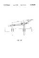
- FIG. 1(a)illustrates, schematically, a prior art apparatus
- FIG. 1(b)illustrates, schematically, an apparatus in accordance with an embodiment of the invention
- FIG. 2illustrates, schematically, use of an apparatus in accordance with an embodiment of the present invention and its operation with in-line arranged cassettes and work stations in accordance with the method of the present invention
- FIG. 3(a)illustrates, schematically, a multi robot system and its operation in accordance with an embodiment of the present invention
- FIG. 3(b)illustrates, schematically, a multiple off-radial cassette handling robot arm system and its operation in accordance with an embodiment of the present invention
- FIG. 4illustrates, schematically, an embodiment of the present invention as used in combination with a sensor array for centering a semiconductor wafer or other circular object;
- FIG. 5illustrates, schematically, a similar apparatus and sensor array to that of FIG. 4 for aligning a flat panel or other angular object.
- FIG. 6(a)illustrates, schematically, a trajectory path for a wafer utilizing a prior art robotic arm lacking yaw motion
- FIG. 6(b)illustrates, schematically, a trajectory path for a wafer utilizing a robotic arm in accordance with the invention which provides yaw motion
- FIG. 7illustrates the various angles used in calculations during computer control of the arm
- FIG. 8illustrates diagrammatically the flow of information to a computer motion controller
- FIG. 9illustrates, in top view, a three hand end effector useful in embodiments of the invention holding three wafers shown in phantom;
- FIG. 10illustrates, in top view, a frog leg type linkage featuring a dual hand end effector in accordance with an embodiment of the invention
- FIG. 11illustrates, in a side partially section view, the embodiment of FIG. 1;
- FIG. 12illustrates, in end view, the embodiment of FIGS. 10 and 11;
- FIG. 13illustrates, in partially section end view in larger size, another embodiment of the invention.
- FIG. 14illustrates, in partially section end view in larger size, yet another embodiment of the invention.
- FIGS. 15a and 15billustrate, in top view, steps in the operation of an embodiment of a frog leg type linkage in accordance with the invention
- FIG. 16illustrates, in top view, the mathematics of a method of motion control in accordance with the invention
- FIGS. 17a and 17billustrate a detail in the structure and operation of the invention
- FIGS. 18a and 18billustrate, in side and plan views, respectively, means for aligning wafers in accordance with an embodiment of the invention
- FIG. 19illustrates, in top view, use of a three hand end effector in an embodiment of the invention
- FIG. 20illustrates, in side sectional partial view, incorporation of Z-motion in an embodiment in accordance with the present invention
- FIGS. 21a and 21billustrate, in side sectional view and plan view respectively, a universally adjustable robotic arm in accordance with one or more embodiments of the invention, the arm illustrated providing both Y motion and E axis rotational motion about a E axis which extends along the length of the end effector;
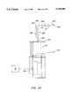
- FIG. 22illustrates, in side sectional view, with an outwardly telescoped mode being shown in dashed lines, an elevator structure in accordance with an embodiment of the present invention
- FIGS. 23illustrates, in enlarged side section view, a portion of the apparatus illustrated in FIG. 22 along with one of the motors used for tilting the elevator;
- FIG. 24illustrates, schematically, in both collapsed and extended form, an elevator as illustrated in FIG. 22 to which a robotic arm mechanism is mounted with the robotic arm mechanism having a sensor as part thereof;
- FIG. 25illustrates, in partial enlarged side sectional view, details of construction of a lower portion of an elevator structure useful in accordance with the embodiments of the present invention
- FIG. 26illustrates, in a view similar to FIG. 25 but with individual parts separately shown in a side and in plan views, details in the elements illustrated in FIG. 25;
- FIGS. 27 and 28illustrate, in views similar, respectively to FIGS. 21a and 21b, an apparatus in accordance with an embodiment of the invention which includes both Y- and J-motion capability;
- FIGS. 29a and 29billustrate, in views similar, respectively to FIGS. 21a and 21b, an apparatus in accordance with an embodiment of the invention which includes a dual end effector with both Y- and J-motion capability for each of the wafer picking up portions (hands)of the end effector;
- FIGS. 30a and 30billustrate, in side partial section and plan view,, an apparatus in accordance with an embodiment of the invention which includes both Y- and J-motion capability and the accessing of cassettes positioned in a plane parallel to the Z axis;
- FIGS. 31a and 31billustrate, in views similar, respectively to FIGS. 21a and 21b, an apparatus in accordance with an embodiment of the invention which includes a dual end effector with Y-, E- and J-motion capability for each of the hands;
- FIG. 32illustrates, in side sectional view, compensation of a robotic arm in accordance with an embodiment of the invention for latitudinal misalignment
- FIG. 33illustrates, schematically, compensation of a robotic arm in accordance with an embodiment of the invention for longitudinal misalignment
- FIGS. 34a and 34billustrate, in plan views, longitudinal misalignment and compensation of a robotic arm in accordance with an embodiment of the invention for the longitudinal misalignment
- FIGS. 35a and 35billustrate, in side partial sectional and plan views, respectively, multiple (two are shown) end effectors, each of which is a dual end effector, with separate yaw motors for each of the dual end effectors;
- FIG. 36illustrates the Y motor section of FIG. 35a in enlarged and more detailed view
- FIG. 37illustrates the minimum end effector working envelope for a dual hand end effector
- FIG. 38illustrates the minimum end effector working envelope for a two Y axis single hand end effector
- FIGS. 39a-39fillustrate one mode of operation in accordance with an embodiment of the invention.
- FIG. 40is a general representation of the elevator structure shown in FIGS. 22-26 wherein all plates of the table are in a symmetrical relationship;
- FIG. 41is a general representation of the deformation which occurs between the joints of the elevator structure shown in FIGS. 22-26 when the upper plate is provided at an angle;
- FIG. 42is a general representation of the elevator structure shown in FIGS. 22-26 representing a first embodiment wherein the bushings around the universal joints are elastic;
- FIG. 43is a representation of the elevator structure shown in FIGS. 22-26 wherein the rod members are elastic.
- FIG. 44is a side view of an alternative embodiment of the elevator structure suitable for use in accordance with the robot of the present invention.
- FIG. 45is a second side view of the robot shown in FIG. 44.
- FIG. 46is a top view of the elevator structure shown in FIG. 44.
- FIG. 47is a top view of the spring mechanism utilized in the elevator structure shown in FIGS. 44-46.
- the present inventionprovides a unique yaw motion to the end effectors of robotic arms which allows the arms to be used more efficiently than can prior art arms which lack yaw motion.
- both roll/or pitch motionis provided.
- the motion of the armcan be controlled via mechanisms which include measuring the rotational rate (and thereby positions) of the radial and rotary drive shafts and of the yaw drive shaft (and the roll and pitch drive shafts, where used) and utilizing a computer to control these quantities such that the end effector of the robotic arm follows a desired path.
- the armretains the capability of straight line motion and, indeed, extends this ability to straight line motion in other than the radial direction as well as to an arbitrary trajectory.
- beltFor a better understanding of the invention it should be noted that the terms “belt”, “belt means”, “pulley” and “pulley means” are, at times, referred to as gearing. It should further be understood that the terms “belt” and “belt means” are used broadly to include toothed and untoothed constructions, chains, fabric belts, woven belts and the like. They may be constructed of any suitable material, natural or synthetic, organic, inorganic, polymeric, composite or metallic. Likewise the terms “pulley” and “pulley means” are used broadly to include toothed and untoothed constructions, constructions which positively engage with respective belts or which engage only frictionally with such belts.
- R, ⁇ and Zare the cylindrical coordinates of the end effector pole, while X, Y, Z are its Cartesian coordinates where ⁇ is the angle between the longitudinal axis of the end effector and the abscise axis of the world coordinate frame;
- the first step towards the solution of this taskis to plan the end effector velocity (linear and angular) at each sampling time.
- the norm of the maximum linear and angular velocity, acceleration and jerkthe first time derivative of the acceleration of the end effector during the motion.
- the control systemis responsible for generating a velocity profile that meets these requirements.
- the velocity profile generatortaking into account the current position of the end effector, calculates its linear and angular velocity vectors. They last are transformed into joint and motor velocities, solving the Inverse Kinetics Problem at velocity level.
- the current motor positionsshould be available (motor positions are given by the encoders and transformed to joint positions through the solution of the Direct Kinematics Problem at position level).
- the motor velocitiesare loaded into the motion controller and the sequence above is repeated at each sampling time until the end of the trajectory is reached.
- FIG. 8sets forth a scheme of control embodying these principals.
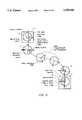
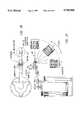
- a prior art robotic arm assembly 10which comprises a robot base, links L1, L2 and L3 plus an end effector 18.
- a radial drive motor Servo Motor 1drives a radial drive shaft 20.
- the radial drive motor Servo Motor 1motivates a gear train 28 which, in turn, drives the radial drive shaft 20.
- each linkhas a proximal end portion and a distal end portion.
- a more detailed description of the robotic arm of FIG. 1(a)can be found in U.S. Pat. No. 5,064,340.
- Each of the linkshas its proximal end portion pivotally mounted to rotate about a respective n th axis.
- the first link L1has its proximal end portion pivotally mounted about a first (primary) axis 21
- the second link L2has its proximal end portion pivotally mounted to rotate about a second axis 23, etc.
- the end effector 18is pivotally mounted to rotate about an n+1 st axis, in the embodiment of FIGS.
- a fourth (end effector) axis 25which is located at the distal end portion of the preceding link (in the embodiment illustrated at the distal end portion of the third link L3).
- the axes of the links and of the end effectorare all parallel to one another.
- Belt means(shown as dashed lines) are each rotated by respective ones of n corresponding pulleys. A first of the pulleys is rotated by the driving end portion of the radial drive shaft 20.
- each succeeding belt means except for the n this arranged to rotate the next successive link about its respective axis.
- the n th belt meansis arranged to rotate the end effector 18 about the n+1 st axis 25.
- FIG. 1(b)lacks the n th belt means and end effector 18 is instead rotated in accordance with the present invention by Servo Motor 3.
- each linkis defined as the distance between a first pivot axis where the proximal end of that link is pivotally mounted and a second pivot axis where the proximal end portion of the next link is pivotally mounted.
- the radial drive rotatable shaft 20rotates relative to a robot base.
- the radial drive rotatable shaft 20motivates a pulley-drive wheel which rotates therewith.
- the drive wheelis coaxial with the first axis 21.
- the first link L1is pivotally mounted to the robot base at a bearing structure.
- a postis mounted to the distal end portion of the first link L1 along a second pivot axis 23.
- the posthas the second effectively cylindrical surface on it with the second effectively cylindrical surface being cylindrical about the second pivot axis 23.
- the second link L2is pivotally mounted relative to the post by bearings 22, whereby the second link L2 is rotatable at its proximal end portion about the second pivot axis 23.
- the second link L2has a second pulley surface aligned opposite the first pulley surface and it has a third pulley surface aligned opposite a fourth pulley surface located about a third axis 27.
- an additional belt/pulley arrangementserves to rotate the end effector 18 which is rotatably mounted via bearings about a post mounted to the distal end portion of the second link L2.
- Beltsserve to impart the needed rotation about the various axes in FIG. 1(a).
- gearingcan be provided in the first link L1 between the first axis 21 and the second axis 23. Such is shown in previously mentioned U.S. Pat. No. 5,064,340.
- radial drive sensor means 90in practice an incremental photo encoder, is provided for measuring a quantity indicative of the rotational position about the axis 21 of the radial drive shaft 20 and for generating an electronic signal representative of the rotational position of the radial drive shaft 20.
- the quantity actually measured which is indicative of the rotational position of the radial drive shaft 20is the rotational position of an extension 26 of the shaft 20, i.e., the rotational position of the radial drive motor, i.e., Servo Motor 1. Since the two quantities are proportional to one another the resulting electronic signal is indicative of the desired quantity, namely, the rotational position of the radial drive shaft 20.
- the photo encodercan be in the nature of a light source and a light sensor aligned to receive light from the light source when the light path is not blocked off (See FIGS. 17a and 17b and the text describing this technology.)
- Means represented by line 92is present for communicating the electronic signal representative of the rotational position of the radial drive shaft 20 to electronic computing means 96.
- rotary drive sensor means 98is provided for measuring a quantity indicative of the rotational position of the rotary drive shaft 78 and for generating an electronic signal representative of the rotational position of the rotary drive shaft 78 about the first axis 21. In practice, the quantity is measured at the intermediate shaft 64.
- Means, represented by line 100is provided for communicating the electronic signal representative of the rotational position of the rotary drive shaft 78 to the electronic computing means 96.
- the electronic computer means 96includes locus computing means 102 for computing the locus of the end effector 18 from the sensed rotational positions of the radial drive shaft 20 and the rotary drive shaft 78 using the geometric relations dictated by the specific lengths of the various links and the diameters of the various pulleys.
- the electronic computing means 96further includes drive controlling means 104 for controlling the radial drive motor, Servo Motor 1, and the rotary drive motor, Servo Motor 2 such that the number of revolutions of the rotary drive shaft 20, n R , divided by the number of revolutions of the radial drive shaft 78, n.sub. ⁇ , is equal to -K so as to position the end effector 18 to follow a radial straight line path and to arrive at a desired locus.
- the -K valuedoes not satisfy this relationship for a non-radial straight line path.
- the control signalis represented by lines 106, 108 to the radial drive motor, Servo Motor 1, and to the rotary drive motor, Servo
- FIG. 1(b)illustrates a basic embodiment of the present invention.
- the end effector 18is rotated by operation of Servo Motor 3 about the axis 25 which can be referred to and thought of as the Y or yaw axis.
- Servo Motor 3is mounted to the distal end portion of the link L3 and its shaft directly rotates the end effector 18.
- Servo Motor 3can be mounted at any desired position so long as it is arranged so as to provide the desired yaw motion.
- the Servo Motor 3can be mounted within any one of the links, e.g., near the Servo Motors 1 and 2. If the Servo Motor 3 is not mounted at the axis 25 appropriate belt and pulley arrangements, like those described for delivering the -rotary and radial motions, are provided so that rotational drive about the yaw axis results.
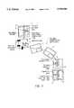
- FIG. 2illustrates an application of the apparatus of FIG. 1(a).
- the work stations, W, and the wafer cassettes, Care not located an equal radial distance from the axis 21 of the robotic arm.
- Using the yaw capabilityit is possible to so align the end effector 18 that it can be inserted in each work station and in the cassettes, as well, in a straight line even though the work stations and cassettes are not radially aligned relative to the axis 21.
- the robotic system describedcan entirely replace expensive small track systems in which the robot is carried (translated) by a track in order to handle in-line arranged cassettes.
- FIG. 3(a)illustrates use of two arms 10, 10' sequentially.
- An arm (not shown) to the left of the arm 10picks up a wafer from any of the three left most cassettes and delivers it for processing within its working envelope. Following processing it delivers the processed wafer to the shared (shaded) cassette at the right extreme of its working envelope.
- the shared cassetteis defined as the cassette in the particular sharing location and each successive cassette will serve as the shared cassette as it passes through the sharing location.
- Arm 10picks up a wafer which has been processed in this manner from any of the cassettes in its working envelope, delivers it for processing and, following processing delivers it to the shaded cassette at the right extreme of its working envelope.
- the arm 10'then carries out similar operations. As many arms as are needed can be placed in sequence in this manner.
- FIG. 3(b)illustrates multiple off-radial cassette handling.
- the conveyor beltmoves until a given set of cassettes enter the working envelope (delineated by a dashed rectangle) of the arm.
- the robot armpicks up a wafer from any of the cassettes within its working envelope and delivers it after processing to another cassette. After the stage finishes all the cassettes from the working envelope are transported by the conveyor belt to the next process stage.
- FIG. 4illustrates use of a robotic arm having yaw motion for centering a semiconductor wafer (which may be misaligned in a cassette C) on the fly (as it traverses its path to a work station W.)
- a semiconductor waferwhich may be misaligned in a cassette C
- Normally such wafersmust be moved onto a chuck to center and rotate them so they are aligned properly for delivery to a work station.
- an edge position measuring devicefor example, an optical sensor such as a CCD sensor, can be positioned conveniently where the wafer is directed within the ambit of the sensor and any deviation of the center of the wafer from its required position is detected.
- the sensor array(in this instance a single sensor constitutes the array) then signals to electronic computer control circuitry which directs the yaw motor (Servo Motor 3) to correct for the misalignment.
- the waferis then delivered to work station W in the proper alignment for processing.
- Position Aa non-centered wafer is in the source cassette.
- the end effector coordinate framecoincides with the source cassette coordinate frame.
- the end effectormoves with respect to its own coordinate frame (translates along the ordinate axis) until the wafer is pulled out of the cassette;
- Position Bthe wafer moves inside the measuring area.
- the displacement of the center of the wafer with respect to the end effector coordinate frameis calculated based on the sensor (CDD) readings.
- the axes of the wafer coordinate frameare parallel to the corresponding axes of the end effector coordinate frame;
- Wafer transporting and centering phasethe wafer is translated and rotated in order to arrive at position D properly positioned (the wafer coordinate frame should be parallel to the destination cassette coordinate frame with ordinate axes coincident. The end effector should move in terms of the wafer coordinate frame (translation along the ordinate axis) until arrival at position E.
- Position Ethe wafer is centered. Its coordinate frame coincides with the destination cassette coordinate frame.
- FIG. 5is very similar to FIG. 4 but demonstrates object alignment on the fly for a display panel P which is rectangular in shape.
- the panelis shown in positions A-D to show its progress on the fly.
- the sensor arrayin this instance includes three sensors, two to define an edge and the third to define a perpendicular edge thereby completely defining the position of the panel.
- Position Aa flat panel is in the source cassette with angular and linear misalignment.
- the end effector coordinate framecoincides with the source cassette coordinate frame.
- the end effectormoves with respect to its own coordinate frame (translates along the ordinate axis) until the panel is pulled out of the cassette;
- Position Bthe flat panel moves inside the measuring area.
- the linear and angular offsets between the end effector coordinate frame and the flat panel coordinate frameare calculated based on the sensor (CDD) readings.
- the axes of the wafer coordinate frameare parallel to the corresponding axes of the end effector coordinate frame;
- Flat panel transporting and aligning phasethe panel is translated and rotated in order to arrive at position C properly positioned and oriented(the panel coordinate frame should be parallel to the destination cassette coordinate frame with ordinate axes coincident.
- the end effectorshould move in terms of the flat panel coordinate frame (translation along the flay panel ordinate axis) until arrival at position D.
- Position Dthe flat panel is aligned. Its coordinate frame coincides with the destination cassette coordinate frame.
- FIG. 6(a)shows operation of a prior art robotic arm which does not include a yaw motor.
- a waferis picked up at position A, the arm retracts along the R direction along the line segment A-B (and stops creating vibration).
- the armthen rotates about the axis 21 along the arc B-C (and stops creating more vibration).
- the armextends along the R direction along the line segment C-D and deposits the wafer at the position D.
- the graph to the right of FIG. 6(a)illustrates the stop/start motion.
- FIG. 6(b)illustrates the same resulting movement, from position A to position D, in a smooth and controlled manner and without any intermediate stops which would cause considerable vibration, particularly in view of the high speeds at which such operations are carried out in the semiconductor industry.
- the pathis along the continuous trajectory A-D.
- FIG. 9illustrates a three hand end effector 118, which has hands extending at 120° from the end effector axis 25 shown in FIG. 1(b).
- the electronic computer means 96controls the yaw motor (Servo Motor 3, as illustrated) utilizing the locus computing means 102 for most efficient operation thereby increasing throughput.
- the provision of controlled yaw motionremoves the necessity of having a two or three hand end effector which has an axis which must be movable across the Z-axis (thereby allowing more efficient motion) and the necessity to utilize in and out linear motion across the Z-axis.
- an additional degree of freedomcan be provided via means, e.g., an additional (5 th ) motor, for rotating the end effector about a roll axis, designated for convenience as an E axis, which is the longitudinal axis of the end effector 18. This allows such panels to be rotated about the roll axis into a vertical plane.
- an additional (5 th ) motorfor rotating the end effector about a roll axis, designated for convenience as an E axis, which is the longitudinal axis of the end effector 18.
- a distalmost axis motor 302 for rotating the end effector 18 about the roll axis 304 of the end effector 18, as illustrated in FIGS. 21a and 21b,can be used in place of the end effector motor (such as Servo Motor 3) in certain instances, in particular for correcting for misalignment of cassettes or workstations from being parallel with the primary axis 21 when tilting is provided of an elevator 310 which transports the arm assembly 10 along the primary axis 21.
- the end effector motorsuch as Servo Motor 3
- the elevator 310tips enough to align the axis 21 with the more or less vertical axis of the cassette/workstation holding wafers/panels and the motor 302 serves to tilt the end effector 18 so that it approaches the wafers/panels in completely proper angular alignment to pick them up and deliver them for processing. Other corrections which are needed are made as explained in more detail below.
- Piezo crystals 311are provided generally equally spaced at 120° about the axis of the elevator structure 310.
- Each piezo crystalhas its own general coordinate that is measured by a respective feedback sensor 313 and is properly controlled so as to result in a given orientation of the plane of the arm links. These serve to sense the tilt of the robot base (lower plate) 328.
- the Y motor and/or the E motorare adjusted as explained below with the positions of each motor being sensed and transmitted to the computer controller which then controls the motors to attain a desired orientation and position.
- the end effector 18includes a proximal section 317 which is pivotally attached to the distalmost link and a distal section 319.
- the roll motoris located on either the proximal section 317 or the distal section 319 of the end effector 18.
- the motor 302is rigidly attached relative to the proximal section 317 and the motor shaft 315 is rigidly attached to the distal section 319. Accordingly, as the shaft 315 is rotated by the roll motor 302 the distal section 319 is rotated about the roll axis 304 relative to the proximal section 317.
- the precise arrangement illustrated for the E motorneed not be used.
- the E motorcan be otherwise positioned and, if necessary, a belt and pulley arrangement may be provided to motivate the desired roll motion. Generally, however, installing the roll motor as illustrated is preferred.
- Appropriate sensorsserve to measure the relative positions of the proximal and distal sections.
- the informationis transmitted to the computer controller which sends control signals to the motors to control the relative positions of the proximal and distal sections.
- Thisprovides roll motion.
- Y motionis provided as described elsewhere herein by operation of the Y motor. All motions are controlled by the computer utilizing sensors which sense the positions of the shafts of the various motors and transmit this information to the computer.
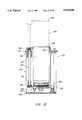
- FIG. 22illustrates a generally universally tiltingly adjustable elevator structure 310 useful in accordance with certain embodiments of the present invention.
- the elevatoris shown both in its retracted form (in solid lines) and in its expanded form (in dashed lines).
- the elevator structure 310is made up of two distinct portions, namely, a rigid frame 312 which includes a base 314 having an upwardly facing generally planar surface 316, a rigid vertical structure 318 having a structure upper end portion 320, the rigid structure 318 extending upwardly generally orthogonally from the planar surface 316 to the structure upper end portion 320 and a flange 322 attached to the structure upper end portion 320, the flange 322 being generally parallel to the planar surface 316.
- a rigid frame 312which includes a base 314 having an upwardly facing generally planar surface 316, a rigid vertical structure 318 having a structure upper end portion 320, the rigid structure 318 extending upwardly generally orthogonally from the planar surface 316 to the structure upper end portion 320 and a flange 322 attached to the structure upper end portion 320, the flange 322 being generally parallel to the planar surface 316.
- the second part of the elevator 310is a movable elevatable structure 324 which is telescopically mounted to the rigid frame 312. It moves up and down through an opening 325 in the flange 322.
- the movable elevatable structure 324includes an upper plate 326, a lower plate 328 which is positioned at a spaced distance from and generally parallel to the upper plate 326 and at least three non-coplanar linearly extending generally parallel members 330.
- Each of the members 330has a respective upper end portion 332 and a respective lower end portion 334.
- Each of the members 330extends from the upper plate 326 to the lower plate 328.
- the members 330are each generally (but not exactly during tilting) orthogonal relative to the plates 326 and 328.
- the non-coplanar membersare substantially equally spaced about the peripheries of the upper plate 326 and the lower plate 328.
- a plurality of upper universal joints 336are supported by the upper plate 326.
- the term "universal joint” as used hereinincludes joints with either two or three degrees of freedom as well as any other kinematically equivalent joint that can be used to restrict the motion of the plate or other member to which it is connected.
- the number of upper universal joints 336is equal to the number of linearly extending members 330.
- Each of the upper universal joints 336is arranged to universally mount the respective upper end portion 332 of a respective one of the linearly extending members 330 to the upper plate 326.
- there are a plurality of lower universal joints 338which are supported by the lower plate 328.
- the number of lower universal joints 338is equal to the number of linearly extending members 330.
- Each of the lower universal joints 338is arranged to universally mount the respective lower end portion 334 of a respective one of the linearly extending members 30 to the lower plate 328.
- Motor means 340is rigidly supported, generally by the base 314. It serves for motivating each of the linearly extending members 330 independently of each other of the linearly extending members 330 toward and away from the base 314.
- the preferred motor meanscomprises three separate motors, one of which, 342, is shown in FIG. 23. Each motor operates via a respective belt and pulley arrangement 344 to rotate a respective lead screw 346 which is mounted for rotation relative to the base 314 and to the flange 322.
- a bracket 352is attached to the linearly extending member 330 and has an extending arm 354 which defines a bore 356 which includes a thread follower structure 357, for example, a ball screw bearing (preferred) or mating threads, which engages with the lead screw 346.
- a thread follower structure 357for example, a ball screw bearing (preferred) or mating threads, which engages with the lead screw 346.
- the elevator structure 310 in accordance with the present inventionis generally useful in combination with an article positioning apparatus 360 as described elsewhere herein which can be suitably mounted to the elevatable structure 324, generally to the upper plate 326 or to the lower plate 328 as illustrated in FIG. 24. As shown it is mounted to the upper plate 326.
- the particular apparatus illustrated in FIG. 24includes an end effector 362 pivotally connected to a forearm 364 which is in turn pivotally connected to a proximal arm 366, which is pivotally connected about an axis 369 to a post 368 which can be conventionally motivated to move vertically to provide Z-axis motion.
- the end effector 362would conventionally include vacuum pickup means which are useful for picking up semiconductor wafers and the like. All are conventionally controlled by control means, namely by the computing means 96.
- FIG. 40shows the tilt mechanism in a symmetrical (all plates parallel) relationship. In this configuration, the distance (I) from the center of the respective joints 338 1 , 338 2 to each other is equal if the symmetrical relationship is maintained.
- FIG. 40shows the tilt mechanism in a symmetrical (all plates parallel) relationship. In this configuration, the distance (I) from the center of the respective joints 338 1 , 338 2 to each other is equal if the symmetrical relationship is maintained.
- FIG. 42shows a first proposed scheme wherein the bushings have an elastic element positioned therein to allow for the variation dI.
- FIG. 43shows a second proposed scheme wherein the rods themselves can elastically deform. It should be apparent to one of average skill that elasticity may occur in both the rods and the joints due to the finite stiffness of the materials used in construction.
- FIGS. 44-47show an alternative embodiment to the elevator table shown in FIGS. 22-26.
- the elevator screws 346-1are positioned within the arm members 330-1 to allow for a more compact arrangement for the elevator structure, making it suitable for applications wherein the physical space for the robot is limited.
- a spring member 360is positioned at the base of the frame 312 to ensure that the parallel arm members 330-1 do not rotate.
- Three motor means 344-1, 344-2, 344-3are coupled to three belt and pulley arrangements 344-01, 344-2, 344-3, respectively, to rotate the screws to raise and lower the platform 322-1 in accordance with the above description.
- a suitable position measuring sensor system 370can include a) signal transmitting means for transmitting a first signal (e.g., a photo or a sonic signal) longitudinally forward from the distal end of the end effector 362 parallel to the workpieces, b) signal detector means (e.g., a photo or a sonic signal detector) for providing a signal indicative of impinging incident energy, and c) energy gathering and transmitting means for gathering energy caused by reflection of the first signal from a workpiece and transmitting such energy to the signal detector means.
- Status signal transmitting meansare provided for transmitting a signal to the control means indicative of the presence or absence of energy caused by reflection of the first signal from a respective one of the workpieces.
- the position measuring sensor system 370can be provided on the end effector 362 for detecting whether or not any wafer, panel, cassette or workstation to be picked up is properly aligned or is misaligned and somehow canted.
- the elevator structure 310can be utilized to tilt the entire article positioning apparatus 360 so that the vacuum pickup on the end effector 362 is aligned to properly pick up the wafer.
- the end effector 362is appropriately tilted about the n th axis 25 or about the longitudinal axis 304 of the end effector 362 utilizing, respectively, the Servo Motor 3 or the motor 302.
- the tilt of the elevator structure 310is adjusted utilizing the Servo motor 3 and the roil motor 302 so that the wafer/panel/etc.
- the article positioning apparatus 360is in proper position for delivery to a wafer/panel processing station in a semiconductor/panel processing operation.
- the article positioning apparatus 360is shown in two positions, one corresponding to full retraction of both the rod 368 and the elevator 310 and the other corresponding to at least partial extension of the elevator 310 and the article positioning apparatus 360.
- the article positioning apparatus 360has a bottom portion 363 which is supported by the upper plate 326 in the embodiment illustrated.
- the article positioning apparatus 360extends upwardly through the generally central opening 325 in the flange 322 to above the upper plate 326.
- FIGS. 22-24there are three lead screw/bracket/linearly extending member combinations (one is shown) equally spaced around the flange 322 which, in this instance, is circular in shape.
- Rigidity to the structureis provided by the rigid vertical structure 318 which in the particular embodiment illustrated comprises three tubes which are rigid and which are attached from the base 314 to the flange 322.
- a pneumatic pressure cylinder 386is attached to a first membrane 384.
- a flange 392is rigidly attached to a second membrane 382 with bolts 379.
- a cylinder rod 389applies a force upon the flange 392.
- the flange 392transmits this force to the second membrane 382.
- the second membrane 382which is rigidly attached with bolts 391 to the bottom of the elevator 310, bows upwardly.
- the first membrane 384has a tendency to bow downwardly.
- a flange 385is spaced apart from and under the first membrane 384.
- a structure 388is attached with its upper end portion 393 attached to the flange 392.
- the structure 388passed through the first membrane 384 in non-contacting relation and has its bottom portion attached to the flange 385.
- An adjustment mechanism 387allows the flange 385 to be positioned closer to or further from the first membrane 384. Accordingly, a gap 381 as defined between the flange 385 and the first membrane 384, determines the travel of the cylinder rod 389 and thereby the extent of the deformation of the first and second membranes 384, 382.
- FIGS. 27 and 28illustrate embodiments of the invention in which yet another motion about a pitch axis of the end effector, designated as J, axis which is perpendicular to the E axis and to the Y axis is provided.
- a pitch motoris provided which acts between the proximal and distal sections of the end effector 18 to provide relative rotation about a J axis.
- This motionis useful in allowing flat panels to be rotated from the horizontal to the vertical. It is also useful to allow cassettes to be readily transferred from, for example, horizontal cassettes or workstations to vertical cassettes or workstations or simply into and/or out of other than horizontally aligned cassettes See cassettes 1, 2 and 3). If both Y and J motion is provided it is not necessary that the cassettes be arranged radially.
- J and E motioncan be provided with a single end effector for maximum versatility. If both J and E motion are provided it becomes necessary to have proximal, central and distal sections of the end effector so as to allow both J and E motion to be attained.
- the J motoris controlled in the same manner as are all other motors via appropriate sensors, transmission of signals to the computer controller and transmission of control signals from the computer controller to the J motor.
- the robotic arm illustratedprovides 7 degrees of freedom and is capable of performing a general controlled motion in three dimensional space.
- the combination of the Y and E axescan be considered as a two degree of freedom wrist attached to a "planar" two dimensional arm movable with two degrees of freedom, R and ⁇ .
- the entire armis spherically attached to a platform that moves vertically (Z direction).
- the rotation (tilt) of the arm around the spherical bearingis controlled by the three piezo crystals.
- Each piezo crystalhas its own generalized coordinate system that is measured by a respective feedback sensor as discussed elsewhere. It is properly controlled so as to result in a given orientation of the plane of the links.
- FIGS. 29a and 29billustrate an embodiment of a robot having a Yaw motor plus a double end effector 718 with each of the end effector distal portions 718a, 718b being rotatable about a respective pitch axis 720a, 720b utilizing its own pitch motor 722a, 722b and its appropriate sensor 724a, 724b which is in communication with and controlled by the computer controller 92.
- Thisserves to minimize the time needed to handle workstations or cassettes when repositioning workpieces.
- the workpieceis picked up by the first end effector portion via orienting its pitch axis and is replaced at the workstation by a workpiece which is already available on the second end effector portion.
- FIGS. 30a and 30billustrate the use of a robotic arm having a J axis to pick up workpieces from both vertically and horizontally aligned cassettes, C.
- FIGS. 31a and 31billustrate a robotic arm with a dual end effector with each wrist region having Y, J and E motions.
- the resultis universally adjustable wrists.
- the use of a tilting elevatoris not needed with this construction since the robot is capable, through use of the available ⁇ , R, Z, Y, E and J motions, of compensating for any misalignment of the cassette/workstation axis relative to the Z axis.
- the armIn the working envelope the arm can reach any arbitrarily situated cassette and can approach the cassette for proper entrance to pick up or deposit workpieces.
- FIG. 32shows a robotic arm 10 and tiltable elevator with the arm portion being shown in two different positions.
- the elevator platformis tilted from the horizontal to correct for a latitudinal misalignment of a cassette there are errors introduced in the R and Z directions, labeled dR and dZ respectively, due to the angular correction, labeled d ⁇ .
- the computer controllersimply makes the required R and Z corrections from the known geometry and the known value of d ⁇ .
- FIG. 33shows the correction needed in the case of compensation for longitudinal cassette misalignments.
- the armis shown in two positions. Due to the separation of the planes of the end effector and the elevator platform on which the robotic arm is supported, the change, d ⁇ , in the angle of the platform leads to errors in the yaw, R and ⁇ directions of the end effector.
- the computer controllermerely calculates the needed corrections and makes them taking into account the known geometry and the known value of d ⁇ .
- FIGS. 34a and 34billustrate the errors with FIG. 34a showing the situation before correction where the right-hand arm is offset a distance dr due to the shift ds of the Z axis of the robotic arm.
- FIG. 34bshows the d ⁇ , dY and dR (R2-R1) corrections which shift the end effector from the right-hand arm of FIG. 34a to the necessary position and orientation.
- a methodfor picking up an ostensibly horizontally (For convenience the workpiece is spoken of as being in a horizontal alignment. Note that the initial orientation is not so limited.) lying generally planar workpiece which is misaligned from the horizontal (or from another loading orientation) and which is one of a plurality of stacked spaced apart workpieces. Basically the end effector 362 is moved to the vicinity of the workpieces. The sensor 370 on the end effector 362 is utilized to measure the alignment of each workpiece prior to its being picked up. When any of the workpieces are misaligned, the degree of misalignment is measured and communicated to computer control means 96.
- the computer control means 96is utilized to control the motor means 340 and the Servo Motor 3 and/or the motor 302 and the article positioning apparatus to align the end effector 362 to pick up the misaligned workpiece.
- the motor means 340is then controlled again to position the workpiece in the desired orientation.
- the present inventionalso provides a method for controlling an arm structure 10 which comprises n longitudinally extending links each having respective proximal and distal end portions when n is 2 or a larger integer.
- the rotational positions of the radial drive shaft, the rotary drive shaft and the end effector drive shaftare all measured. Electronic signals representative of such rotational positions are generated.
- the electronic signals representative of the rotational positions of the various drive shaftsare communicated to electronic computer means and treated in the manner indicated diagrammatically in FIG. 8.
- the electronic computer meanscomputes the locus of the end effector 10 from the electronic signals representative of the rotational positions of the drive shafts. It also controls the drive motors to move and position the end effector in any desired location within its reach.
- FIGS. 35a and 35billustrate an embodiment of the invention which includes a plurality of Y axis end effectors (two end effectors 1002, 1004 are shown but more are practical and readily implemented), each of which is a dual end effector in the sense of having two hand portions, 1002a, 1002b and 1004a, 1004b, respectively, each.
- the Y axes of the two end effectors 1002, 1004are coextensive.
- Separate Y motors 1006, 1008drive each end effector 1002, 1004 about the common Y axis 1010. The drive details are seen best in FIG. 36.
- FIG. 35bshows the end effectors 1002, 1004 at right angles from one another for clarity.
- an advantage of this embodiment of the inventionis that they can alternatively be rotated so that one is below the other as seen in FIG. 35a.
- a dual handed end effectoris shown for both end effectors 1002, 1004, it will be apparent that one or both can be single handed, double handed, triple handed, etc.
- the positions of the respective Y motorscan be determined by sensors and the information can be transmitted to the computer controller 92 which can control and correlate their operation with the operation of the R, Z, ⁇ motors and the elevator motors to provide extreme versatility of operation.
- motor 1008turns, via an intermeshing gear arrangement 1012, a hollow cylindrical shaft 1014 which is supported, via bearings 1016, by a post 1018 supported and extending upwardly from the distal end portion of the distalmost link of the robotic arm 10.
- a bottommost portion 1020 of the shaft 1014is drivingly connected to a central portion 1004c of the end effector 1004.
- a coaxial hollow cylindrical shaft 1022is supported, via bearings 1024, by the shaft 1014.
- a bottommost portion 1026 of the shaft 1022is drivingly connected to a central portion 1002c of the end effector 1002.
- the motor 1006, via intermeshing gear d rive train 1028,drives rotation of the shaft 1022.
- FIG. 37shows the minimum working envelope of a robot with a single Y axis and a double (two-handed) end effector.
- the circleindicates the minimum working envelope needed to have two arms with this construction.
- FIG. 38shows the minimum working envelope, again indicated by a circle, for a pair of single end effectors (one hand each) but with a double Y axis drive wherein each end effector is independently controlled by its own motor.
- the reduced minimum working enveloperesults because of the ability to stack one of the end effectors above the other.
- the combination of two Y drives and dual end effectorsallows one and the same cassette or process station to be reached by both hand portions of the end effectors without rotation about the ⁇ axis.
- the replacement of the dual end effectors by two single end effectors each driven by a separate Y motorallows very fast wafer exchange in a process station without increasing the minimum working envelope (The minimum working envelope is the same as that for a Y axis rotatable robot with a single end effector due to the ability to position on ⁇ end effector over the other.)
- Such exchangesare a bottleneck in many wafer processing processes.
- FIGS. 39a-39fillustrate an example of an embodiment as just described.
- a processed waferis present in a workstation and the arm is holding another wafer ready for processing.
- the armextends in a straight line from the FIG. 39a position to the FIG. 39b position and then withdraws in a straight line to the FIG. 39c position.
- both Y motorsare motivating movement about the two Y coaxial axes to guarantee the straight line path and to further assure that the end effector carries the not yet processed wafer within the working envelope the space between the straight horizontal lines in the Figures.
- FIG. 39dillustrates the rotation of the processed wafer to the right and the beginning of straight line entry of the not yet processed wafer into the workstation.
- FIGS. 39e and 39fshow completion of loading of the not yet processed wafer into the workstation.
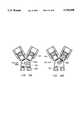
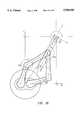
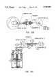
- FIGS. 10-12show one embodiment of the frogs leg type linkage in accordance with an embodiment of the invention.
- a robotic arm mechanism 410includes a relatively static structure 412 by which a frog leg type linkage 414 is supported via a pair of different height tubular members 416,418.
- the frog leg type linkage 414includes a pair of proximal links 420,422 having respective proximal end portions 424,426 and respective distal end portions 428,430.
- the proximal end portions 424,426are respectfully pivotally mounted at the tubular members 416,418 for rotation about respective proximal axes 432,434 at what will be referred to as the shoulders of the mechanism 410.
- a pair of distal links 436,438have proximal end portions 440,442 respectively pivotally mounted to the distal end portions 428,430 of the proximal links 420,422 for rotation about respective axes 444,446 at what will be referred to as the elbows of the mechanism 410.
- the distal links 436,438have respective distal end portions 448,450 pivotally mounted for rotation relative to each other, and to an end effector 452, about a distal axis 454 at what will be referred to as the wrist of the mechanism 410. While different length links can be used it is highly desirable that the proximal links 420,422 be of the same length as one another and that the distal links 436,438 be of the same length as one another. It is not necessary to have all of the links equal in length to one another.
- a shoulder motor 456is seen in FIG. 11. It provides motion at the shoulders as shown by the arrow in FIG. 1.
- An elbow motor 458is seen in FIG. 10. As the elbow motor extends or contracts along the length of the proximal link 420 it causes rotation about the elbows.
- a yaw motor 460shown in FIGS. 11 and 12, causes yaw motion about the wrist.
- An electronic processor 96is connected to receive signals as represented by signal receiving line 92 indicative of the degree of rotation of the shoulder motor 456 and of the wrist motor 460 and of the degree of extension of the elbow motor 458 as provided by sensors attached to measure these quantities.
- the electronic processoralso, via control lines indicated at 100,106,108, serves to transmit signals which control operation of the motors 456,458,460 so as to position the end effector 452 in any desired orientation. It is clear that since the links of the linkage 414 are constrained by their connection to move together only a single shoulder motor and a single elbow motor are necessary to provide any desired motion. E and/or J motion can be provided as desired or necessary as c an a tilting elevator.
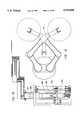
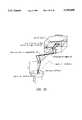
- FIG. 13illustrates another frog legs structure in accordance with an embodiment of the invention.
- a robotic arm mechanism 510is shown with the motor 560 differently positioned and where wrist motion is provided motivated by rotary motion of a shaft 568 of the motor 560.
- Appropriate belt and pulley meansare provided to drive the wrist as the shaft 568 rotates.
- the shaft 568rotates a pulley 570 which, via a belt 572 and pulley 574, rotates a shaft 576 which rotates in bearings 578.
- the shaft 576rotates a pulley 580 which, via a belt 582 and pulley 584, rotates a shaft 586 which rotates in bearings 588 and which is connected at its upper region 590 to drive rotation of the dual end effector 552.
- the elbow motor 558as can be seen by reference to FIG. 13, has a rotating shaft 592 which drives a pulley 594.
- a belt 596transmits the power to a pulley 598 which rotates a shaft 600 in bearings 602.
- the shaft 600has an upper region 604 which is connected to the proximal end portion 540 of the distal link 536 and thereby drives relative rotation about the elbow between the proximal link 520 and the corresponding distal link 536.
- the elbow motoris connected to drive an opposite linkage, i.e., a different pair of proximal and distal links, than is the shoulder motor. This is for ease of construction.
- the belt and pulley arrangements for providing elbow and wrist motionare in opposite linkages since they could otherwise interfere with one another.
- FIG. 14is very similar to FIG. 13. The only exception is with respect to the direction the shaft 586 extends from the pulley 584 and the corresponding changes in position of the associated link and the shaft 600.
- FIGS. 15a and 15billustrate the reach of the arm mechanism 510, 610 in schematic top views.
- FIG. 15aa plurality of workpiece containing cassettes 605 (2 are illustrated) and/or of workstations 606 are shown. It will be noted that they, the workstations 606 as well as the cassettes 605, are not located radially from the center of the robotic arm mechanism 510, 610 so that an arm which could only move in the R and ⁇ directions could not cause its end effector to enter them perpendicularly as does the end effector 552 of the arm mechanism 510, 610 present invention.
- the arm mechanism 510, 610can be aligned and advanced or retracted to pass orthogonally into or out of any of the cassettes/workpieces 605, 606.
- the end effector 552it is possible to so align the end effector 552 that it can be inserted in each workstation 606 and in the cassettes 605, as well, in a straight line even though the work stations 606 and cassettes 605 are not radially aligned relative to the shoulders.
- the robotic system describedcan entirely replace expensive small track systems in which the robot is carried (translated) by a track in order to handle in-line arranged cassettes. These motions are attainable due to the presence of the wrist motor.
- an end effector 552which has two or more hands such as the two hands 552a, 552b illustrated, is particularly efficient and provides very quick operation with low down time. Use of additional hands increases the advantage, within reason. A three hand end effector allows still more efficiency of operation. Of course the workpieces take up space and the cassettes have limited size openings so the number of hands should not be increased so much as to create interference with operation.
- the linksare offset vertically from one another (See FIGS. 13 and 14) to allow the linkage 514 to pass over each other and over the static structure 512 so as to allow the motions illustrated in FIG. 15.
- shoulder motor sensor means 620(shown in FIG. 13), in practice an incremental photo encoder, is provided for measuring a quantity indicative of the rotational position about the axis 544 of the shoulder motor drive shaft 622 and for generating an electronic signal representative of the rotational position of the shoulder motor drive shaft 622.
- motor sensorsare packaged within an extension 621 of the motor housing and are available commercially.
- the resulting electronic signalis indicative of the desired quantity, namely, the rotational position of the shoulder motor drive shaft 622.
- the photo encodercan be in the nature of a light source and a light sensor aligned to receive light from the light source when the light path is not blocked off.
- the light beam from the light sourceis directed parallel to the rotating shaft which has a generally circular disc mounted on it between the light source and the light sensor and extending into the light beam.
- the dischas alternating transparent and opaque areas and the number of pulses generated at the light sensor during rotation of the motor is indicative of the speed of the motor and thereby of the rotational position of the shaft.
- FIGS. 17a and 17billustrate the structure.
- Means represented by line 92(FIG. 12) is present for communicating the electronic signal representative of the rotational position of the shoulder motor drive shaft to electronic computing means 96.
- elbow motor drive sensor means 624is provided for measuring a quantity indicative of the extension (FIGS. 10-12) of a follower 626 threadably mounted to and extending with rotation of the elbow motor drive shaft in FIG. 10 or of the rotational position of the elbow motor drive shaft 592 (FIG. 13) and for generating an electronic signal representative of the quantity measured.
- the follower 626is attached to the proximal end portion 540 of the distal link 536 whereby the angle between the links changes as the follower 626 is moved due to rotation of the elbow motor drive shaft.
- a sensor set up as shown in FIGS. 17a and 17bwill be used to measure the rotation of the shaft 592 and from that information and the degree of pitch of the threading on the shaft 592 the extension can be calculated and from that and known geometric relations the angle between the proximal and distal links can be calculated and adjusted as desired.
- Means, represented by line 92,is provided for communicating the electronic signal representative of the position of the follower 626 or of the elbow motor drive shaft 592 to the electronic computing means 562.
- FIGS. 17a and 17bThe sensor means of the invention are illustrated in FIGS. 17a and 17b.
- An extension 700 of the respective motor shaft 568,592,622 within the housing of the respective motor 560,558,556has a disk 702 which rotates with the extension 700.
- a respective sensor 620,624,627, labeled 704 in FIG. 17abounces a beam off the bottom of the disk 702 and detects when reflection occurs.
- the disk 702has a plurality of reflective portions separated by a plurality of non-reflective or open portions See FIG. 17b.) The beam is reflected only by the reflective portions. Since the positioning and separation of the reflective and non-reflective portions are known the resulting signal is proportional to the speed of rotation of the respective shaft.
- the electronic computer means 562includes locus computing means for computing the locus of the end effector 554 from the sensed positions of the drive shafts, and/or of the follower 626, using the geometric relations dictated by the specific lengths of the various links and the diameters of the various pulleys.
- the electronic computing means 562further includes drive controlling means for controlling the shoulder drive motor 556 and the elbow drive motor 558 such that the locus 554 of the end effector moves along the desired trajectory which can be any arbitrary planar curve including, if desired, a straight line.
- FIGS. 18a and 18billustrate use of a sensor 800 placed on the end effector 552 in conjunction with a workpiece alignment chuck 802.
- the chuck 802is used to rotate wafers placed on it so as to allow detection and positioning of any flats which may be present and also to allow centering of the wafer geometric center with the axis of rotation of the chuck 802.
- a wafer 804is illustrated as being on the chuck 802.
- the sensorhas an opening 806 which can accept the periphery of the wafer.
- a detecting beamcan pass from a top portion 808 of the sensor to a bottom portion 810 and be detected there or the beam can be reflected back towards the sensor in the top portion 808 and detected there.
- the edge of the wafercan be detected as the chuck 802 holding the wafer 804 rotates wherefrom information with respect to location and orientation of any flats can be extracted and the position of the geometric center of the wafer 804 can be determined.
- the opposite end 812 of the end effector 552can then pick up the wafer in a desired orientation and deliver it to a work station.
- FIG. 19illustrates a three handed end effector 910 which can readily replace the two handed end effector 552 illustrated in other Figures.
- FIG. 20illustrates a mechanism as shown in FIG. 13 to which a Z-axis motor 950 has been added along with a lead screw 952 which the Z-motor 500 drives and a lead screw follower bracket 954 which serves to lift a frame 956 on which the motors 556 and 560 are carried, thereby providing Z-movement.
- the present inventionthus provides a method for controlling the arm mechanisms 510 and 610.
- the linear position of the elbow motor drive shaft and the rotational positions of the shoulder motor drive shaft and the wrist drive shaftare all measured.
- Electronic signals representative of such positionsare generated.
- the electronic signals representative of the positions of the radial, rotary and end effector drive shaftsare communicated to electronic computer means in the manner indicated diagrammatically in FIG. 12.
- the electronic computer meanscomputes the locus of the end effector 552 from the electronic signals representative of the positions of the drive shafts. It also controls the drive motors to move and position the end effector in any desired location within its reach.
- the rotational positions of the elbow motor drive shaft, the shoulder motor drive shaft and the wrist drive shaftare all measured. Electronic signals representative of such rotational positions are generated. Thereafter, the procedure is as with the arm mechanism 510.
- the inventionfurther provides a method of processing workpieces such as semiconductor wafers and flat panel displays.
- a plurality of generally parallel wafers/panelsare positioned in one or more cassettes with the cassettes not necessarily having axes which are precisely parallel to the primary axis of a robotic arm.
- the armincludes a motor for selectively independently rotating an end effector about a Yaw axis and/or a roll axis and/or a pitch axis.
- the armincludes means for monitoring the R, ⁇ and Z positions of the arm and the Y and/or E and/or J positions of the wrist of the arm as well as computer control means for controlling such positions.
- sensor meansare also provided for measuring the alignments of each workpiece as it is to be picked up by the arm.
- the wafersare picked up in turn with the computer control means controlling the arm so that each workpiece is picked up and delivered progressively to each workstation in proper alignment for processing at that workstation.
- the resultis an improved yield of acceptable completed workpieces produced with
- the present inventionprovides a robotic arm structure 10,510,610 useful for a number of things, particularly for positioning semiconductor wafers for processing and for positioning display panels for processing.
- the systemprovides far more flexibility for the design engineer and greatly reduces vibrations during operation of the arm structure. Increased throughput of acceptable workpieces results.
Landscapes
- Engineering & Computer Science (AREA)
- Health & Medical Sciences (AREA)
- General Health & Medical Sciences (AREA)
- Orthopedic Medicine & Surgery (AREA)
- Robotics (AREA)
- Mechanical Engineering (AREA)
- Manipulator (AREA)
- Container, Conveyance, Adherence, Positioning, Of Wafer (AREA)
- Numerical Control (AREA)
Abstract
Description
Claims (42)
Priority Applications (10)
| Application Number | Priority Date | Filing Date | Title |
|---|---|---|---|
| US08/788,898US5789890A (en) | 1996-03-22 | 1997-01-23 | Robot having multiple degrees of freedom |
| AU23314/97AAU2331497A (en) | 1996-03-22 | 1997-03-18 | Robot having multiple degrees of freedom |
| JP53361497AJP4750231B2 (en) | 1996-03-22 | 1997-03-18 | Workpiece processing system |
| PCT/US1997/004283WO1997035241A1 (en) | 1996-03-22 | 1997-03-18 | Robot having multiple degrees of freedom |
| KR1019980707464AKR20000064731A (en) | 1996-03-22 | 1997-03-18 | Robot with multiple degrees of freedom |
| EP97916045AEP0888581A4 (en) | 1996-03-22 | 1997-03-18 | Robot having multiple degrees of freedom |
| US09/079,850US6037733A (en) | 1996-03-22 | 1998-05-15 | Robot having multiple degrees of freedom |
| US09/129,110US6121743A (en) | 1996-03-22 | 1998-08-04 | Dual robotic arm end effectors having independent yaw motion |
| JP2008308933AJP5133860B2 (en) | 1996-03-22 | 2008-12-03 | Robot arm structure, workpiece processing system, and system including robot arm structure and sensor array |
| JP2012174339AJP2012223880A (en) | 1996-03-22 | 2012-08-06 | Method for controlling robot arm structure, robot arm mechanism, robot arm structure, workpiece processing system, and product manufacturing method |
Applications Claiming Priority (4)
| Application Number | Priority Date | Filing Date | Title |
|---|---|---|---|
| US1386296P | 1996-03-22 | 1996-03-22 | |
| US2154696P | 1996-07-11 | 1996-07-11 | |
| US2424296P | 1996-08-20 | 1996-08-20 | |
| US08/788,898US5789890A (en) | 1996-03-22 | 1997-01-23 | Robot having multiple degrees of freedom |
Related Child Applications (2)
| Application Number | Title | Priority Date | Filing Date |
|---|---|---|---|
| US09/079,850ContinuationUS6037733A (en) | 1996-03-22 | 1998-05-15 | Robot having multiple degrees of freedom |
| US09/129,110Continuation-In-PartUS6121743A (en) | 1996-03-22 | 1998-08-04 | Dual robotic arm end effectors having independent yaw motion |
Publications (1)
| Publication Number | Publication Date |
|---|---|
| US5789890Atrue US5789890A (en) | 1998-08-04 |
Family
ID=27486334
Family Applications (2)
| Application Number | Title | Priority Date | Filing Date |
|---|---|---|---|
| US08/788,898Expired - LifetimeUS5789890A (en) | 1996-03-22 | 1997-01-23 | Robot having multiple degrees of freedom |
| US09/079,850Expired - LifetimeUS6037733A (en) | 1996-03-22 | 1998-05-15 | Robot having multiple degrees of freedom |
Family Applications After (1)
| Application Number | Title | Priority Date | Filing Date |
|---|---|---|---|
| US09/079,850Expired - LifetimeUS6037733A (en) | 1996-03-22 | 1998-05-15 | Robot having multiple degrees of freedom |
Country Status (6)
| Country | Link |
|---|---|
| US (2) | US5789890A (en) |
| EP (1) | EP0888581A4 (en) |
| JP (3) | JP4750231B2 (en) |
| KR (1) | KR20000064731A (en) |
| AU (1) | AU2331497A (en) |
| WO (1) | WO1997035241A1 (en) |
Cited By (96)
| Publication number | Priority date | Publication date | Assignee | Title |
|---|---|---|---|---|
| US5929585A (en)* | 1996-11-19 | 1999-07-27 | Sony Corporation | Robot system and its control method |
| WO2000007780A1 (en)* | 1998-08-04 | 2000-02-17 | Genmark Automation, Inc. | Robot having multiple degrees of freedom |
| US6037733A (en)* | 1996-03-22 | 2000-03-14 | Genmark Automation | Robot having multiple degrees of freedom |
| US6085125A (en)* | 1998-05-11 | 2000-07-04 | Genmark Automation, Inc. | Prealigner and planarity teaching station |
| US6157450A (en)* | 1998-03-09 | 2000-12-05 | Chapman Instruments | Automated optical surface profile measurement system |
| US6242879B1 (en)* | 2000-03-13 | 2001-06-05 | Berkeley Process Control, Inc. | Touch calibration system for wafer transfer robot |
| US6323616B1 (en)* | 1999-03-15 | 2001-11-27 | Berkeley Process Control, Inc. | Self teaching robotic wafer handling system |
| WO2002012970A1 (en)* | 2000-08-09 | 2002-02-14 | Genmark Automation, Inc. | Robot motion compensation system |
| US6356804B1 (en)* | 1998-03-24 | 2002-03-12 | Advanced Micro Devices, Inc. | Automated material handling system method and arrangement |
| US6400115B1 (en) | 1999-09-28 | 2002-06-04 | Tazmo Co., Ltd. | Horizontal multi-joint industrial robot and a control method thereof |
| US6494666B2 (en) | 2001-01-26 | 2002-12-17 | Fortrend Engineering Corporation | Simplified and enhanced SCARA arm |
| US6514032B1 (en) | 2000-02-01 | 2003-02-04 | Tazmo Co., Ltd. | Substrate transfer system |
| US6520727B1 (en) | 2000-04-12 | 2003-02-18 | Asyt Technologies, Inc. | Modular sorter |
| US6532403B2 (en)* | 2000-04-21 | 2003-03-11 | Microtool, Inc | Robot alignment system and method |
| US6593718B1 (en) | 1999-09-28 | 2003-07-15 | Tazmo Co., Ltd. | Horizontal multi-joint industrial robot |
| US6614201B2 (en) | 2000-02-07 | 2003-09-02 | Tazmo Co., Ltd. | Substrate transfer system |
| US6643563B2 (en) | 2001-07-13 | 2003-11-04 | Brooks Automation, Inc. | Trajectory planning and motion control strategies for a planar three-degree-of-freedom robotic arm |
| US6662673B1 (en)* | 1999-04-08 | 2003-12-16 | Applied Materials, Inc. | Linear motion apparatus and associated method |
| US6669434B2 (en) | 2000-11-17 | 2003-12-30 | Tazmo Co., Ltd. | Double arm substrate transport unit |
| US20040148048A1 (en)* | 2002-11-11 | 2004-07-29 | Farnworth Warren M. | Methods for recognizing features as one or more objects are being fabricated by programmed material consolidation techniques |
| US6781337B2 (en) | 2001-10-17 | 2004-08-24 | Japan Servo Co., Ltd. | Multi-joint type industrial robot |
| US6791291B2 (en) | 2001-10-01 | 2004-09-14 | Japan Servo Co., Ltd. | Multi-joint type industrial robot and arm unit thereof |
| US20040179930A1 (en)* | 2003-03-10 | 2004-09-16 | Keisuke Kondoh | Articulated carrying device |
| US6960057B1 (en)* | 1998-09-30 | 2005-11-01 | Brooks Automation, Inc. | Substrate transport apparatus |
| US20060216137A1 (en)* | 2004-07-02 | 2006-09-28 | Katsunori Sakata | Carrying apparatus and carrying control method for sheet-like substrate |
| US20070010898A1 (en)* | 2005-06-08 | 2007-01-11 | Martin Hosek | Scalable motion control system |
| US20070020082A1 (en)* | 2005-07-11 | 2007-01-25 | Caveney Robert T | Unequal link SCARA arm |
| US20070147961A1 (en)* | 2005-11-10 | 2007-06-28 | Hugo Salamanca | Robot system and method for maintenance of base plates in electrometallurgical and industrial processes |
| US20070144894A1 (en)* | 2005-11-10 | 2007-06-28 | Hugo Salamanca | Robot system and method for cathode stripping in electrometallurgical and industrial processes |
| US20070144005A1 (en)* | 2005-11-10 | 2007-06-28 | Hugo Salamanca | Robot system and method for reposition and/or removal of base plates from cathode stripping machines in electrometallurgical processes |
| US20070152616A1 (en)* | 2005-11-10 | 2007-07-05 | Hugo Salamanca | Robot system and method for cathode selection and handling procedures after the harvest |
| US20070169230A1 (en)* | 2005-11-10 | 2007-07-19 | Hugo Salamanca | Robot system and method for removing sticks and/or foreign elements from conveyor belts |
| US20070180678A1 (en)* | 2005-11-10 | 2007-08-09 | Hugo Salamanca | Robot system and method for bolt removal from SAG and/or ball mills in ore concentration processes |
| US20070185610A1 (en)* | 2005-11-10 | 2007-08-09 | Hugo Salamanca | Robot system and method for the application of dislodging material and pin positioning in casting wheels |
| US20070217897A1 (en)* | 2006-03-15 | 2007-09-20 | Mjc Probe Inc. | Multi-Directional Gripping Apparatus |
| US20070262267A1 (en)* | 2005-12-01 | 2007-11-15 | Epion Corporation | Method and apparatus for scanning a workpiece through an ion beam |
| US20070267043A1 (en)* | 2005-11-10 | 2007-11-22 | Hugo Salamanca | Robot system and method for washing and unclogging procedures of machines under maintenance |
| US20070299556A1 (en)* | 2005-11-10 | 2007-12-27 | Hugo Salamanca | Robot system and method for scrap bundling in metal smelting and refining processes |
| US20080041183A1 (en)* | 2006-06-28 | 2008-02-21 | Genmark Automation, Inc. | Belt-driven robot having extended Z-axis motion |
| US20080121064A1 (en)* | 2006-06-28 | 2008-05-29 | Genmark Automation, Inc. | Robot with belt-drive system |
| US20090099688A1 (en)* | 2005-11-10 | 2009-04-16 | Hugo Salamanca | Integral robot system and method for the dislodging process and/or anode handling from casting wheels |
| US20090101179A1 (en)* | 2005-11-10 | 2009-04-23 | Hugo Salamanca | Robot system and method for molybdenum roasting furnaces cleaning procedures |
| US20090121061A1 (en)* | 2005-11-10 | 2009-05-14 | Hugo Salamanca | Robot system and method for unblocking the primary crusher |
| US20090177324A1 (en)* | 2005-11-10 | 2009-07-09 | Hugo Salamanca | Robot system and method for maxibags sampling in ore concentration processes |
| US20090238663A1 (en)* | 2006-04-11 | 2009-09-24 | Longyear Tm, Inc. | Drill rod handler |
| US20090314423A1 (en)* | 2003-09-26 | 2009-12-24 | Chris Savarese | Apparatuses and methods relating to findable balls |
| US20090324160A1 (en)* | 2008-06-30 | 2009-12-31 | Intuitive Surgical, Inc. | Fixture for shape-sensing optical fiber in a kinematic chain |
| US20100021271A1 (en)* | 2006-04-11 | 2010-01-28 | Keith Littlely | Drill rod handler |
| US20100057254A1 (en)* | 2006-11-13 | 2010-03-04 | Salamanca Hugo P | Methods for using robotics in mining and post-mining processing |
| US20100293777A1 (en)* | 2003-09-26 | 2010-11-25 | Chris Savarese | Methods and apparatuses relating to findable balls |
| US20110118873A1 (en)* | 2008-07-10 | 2011-05-19 | Kawasaki Jukogyo Kabushiki Kaisha | Robot and instruction method thereof |
| US20120253511A1 (en)* | 2011-03-31 | 2012-10-04 | Sinfonia Technology Co., Ltd. | Robot arm apparatus |
| WO2013022622A3 (en)* | 2011-08-08 | 2013-03-28 | Applied Materials, Inc | Systems having multi-linkage robots and methods to correct positional and rotational alignment in multi-linkage robots |
| US20130156531A1 (en)* | 2010-08-27 | 2013-06-20 | Kawasaki Jukogyo Kabushiki Kaisha | Plate-shaped member storage rack, plate-shaped member transfer facility, and plate-shaped member storing method |
| WO2013120054A1 (en)* | 2012-02-10 | 2013-08-15 | Brooks Automation, Inc. | Substrate processing apparatus |
| US20130216348A1 (en)* | 2012-02-16 | 2013-08-22 | Lian Hok Tan | Apparatus for transferring a solar wafer or solar cell during its fabrication |
| US20140067119A1 (en)* | 2012-08-31 | 2014-03-06 | Seiko Epson Corporation | Robot |
| CN103733324A (en)* | 2011-08-08 | 2014-04-16 | 应用材料公司 | Robot systems, apparatus, and methods adapted to transport substrates in electronic device manufacturing |
| WO2013039550A3 (en)* | 2011-09-13 | 2014-04-17 | Persimmon Technologies Corporation | Method for transporting a substrate with a substrate support |
| US8791430B2 (en) | 2011-03-04 | 2014-07-29 | Tel Epion Inc. | Scanner for GCIB system |
| US20150127159A1 (en)* | 2013-11-05 | 2015-05-07 | Seiko Epson Corporation | Force detecting device, robot, electronic component conveying apparatus |
| US9029808B2 (en) | 2011-03-04 | 2015-05-12 | Tel Epion Inc. | Low contamination scanner for GCIB system |
| US9119655B2 (en) | 2012-08-03 | 2015-09-01 | Stryker Corporation | Surgical manipulator capable of controlling a surgical instrument in multiple modes |
| US9226796B2 (en) | 2012-08-03 | 2016-01-05 | Stryker Corporation | Method for detecting a disturbance as an energy applicator of a surgical instrument traverses a cutting path |
| US20160084706A1 (en)* | 2014-09-22 | 2016-03-24 | Antonio Maccari | Tool for positioning a scanning device |
| US9480534B2 (en) | 2012-08-03 | 2016-11-01 | Stryker Corporation | Navigation system and method for removing a volume of tissue from a patient |
| US20160351425A1 (en)* | 2015-05-29 | 2016-12-01 | Semes Co., Ltd. | Teaching method and substrate treating apparatus using the same |
| US20170038189A1 (en)* | 2015-08-03 | 2017-02-09 | Hexagon Technology Center Gmbh | Scara structured coordinate measuring machine with belt drive guided probe head |
| US9820818B2 (en) | 2012-08-03 | 2017-11-21 | Stryker Corporation | System and method for controlling a surgical manipulator based on implant parameters |
| US9895803B1 (en)* | 2015-06-19 | 2018-02-20 | X Development Llc | Calculating trajectory corridor for robot end effector |
| CN107799447A (en)* | 2016-08-29 | 2018-03-13 | 株式会社爱发科 | Base board delivery device, film formation device and substrate carrying method |
| US9921712B2 (en) | 2010-12-29 | 2018-03-20 | Mako Surgical Corp. | System and method for providing substantially stable control of a surgical tool |
| US10002781B2 (en) | 2014-11-10 | 2018-06-19 | Brooks Automation, Inc. | Tool auto-teach method and apparatus |
| US10052756B2 (en)* | 2014-10-30 | 2018-08-21 | Nidec Sankyo Corporation | Industrial robot |
| US10155309B1 (en) | 2017-11-16 | 2018-12-18 | Lam Research Corporation | Wafer handling robots with rotational joint encoders |
| CN109419555A (en)* | 2017-08-28 | 2019-03-05 | 圣纳普医疗(巴巴多斯)公司 | Registration arm for surgical navigation systems |
| WO2019071077A1 (en)* | 2017-10-05 | 2019-04-11 | Brooks Automation, Inc. | Substrate transport apparatus with independent accessory feedthrough |
| TWI664515B (en)* | 2014-09-26 | 2019-07-01 | 日商迪思科股份有限公司 | Processing device |
| US10369702B2 (en)* | 2016-10-17 | 2019-08-06 | Raytheon Company | Automated work piece moment of inertia (MOI) identification system and method for same |
| US10399222B2 (en) | 2012-08-31 | 2019-09-03 | Seiko Epson Corporation | Robot |
| US10569417B1 (en)* | 2019-01-25 | 2020-02-25 | Mujin, Inc. | Robotic system with enhanced scanning mechanism |
| US10580676B2 (en)* | 2014-09-08 | 2020-03-03 | Kabushiki Kaisha Yaskawa Denki | Robot system and carrying method |
| US10661456B2 (en)* | 2017-06-30 | 2020-05-26 | Seiko Epson Corporation | Force detection apparatus and robot |
| CN111457871A (en)* | 2019-01-21 | 2020-07-28 | 波音公司 | Non-destructive inspection apparatus and method of inspecting test article |
| US10870204B2 (en) | 2019-01-25 | 2020-12-22 | Mujin, Inc. | Robotic system control method and controller |
| US20210057251A1 (en)* | 2019-08-22 | 2021-02-25 | Kawasaki Jukogyo Kabushiki Kaisha | Substrate transport robot, substrate transport system, and substrate transport method |
| US11027435B2 (en) | 2018-12-04 | 2021-06-08 | Raytheon Company | Automated work piece testing system and method for same |
| US11198227B2 (en) | 2018-12-04 | 2021-12-14 | Raytheon Company | Adjustable ballast system and method for same |
| US11202682B2 (en) | 2016-12-16 | 2021-12-21 | Mako Surgical Corp. | Techniques for modifying tool operation in a surgical robotic system based on comparing actual and commanded states of the tool relative to a surgical site |
| CN114027988A (en)* | 2021-12-07 | 2022-02-11 | 临沂大学 | Three-degree-of-freedom continuum robot main manipulator and working method thereof |
| CN114420594A (en)* | 2021-12-29 | 2022-04-29 | 上海至纯洁净系统科技股份有限公司 | A wafer cleaning and etching system that effectively achieves high temperature chemical etching reaction |
| CN114628311A (en)* | 2022-05-17 | 2022-06-14 | 智程半导体设备科技(昆山)有限公司 | Wafer transmission device and semiconductor equipment |
| US11413744B2 (en) | 2020-03-03 | 2022-08-16 | Applied Materials, Inc. | Multi-turn drive assembly and systems and methods of use thereof |
| US11521869B2 (en)* | 2017-03-15 | 2022-12-06 | Lam Research Corporation | Reduced footprint platform architecture with linear vacuum transfer module |
| CN117381837A (en)* | 2023-12-12 | 2024-01-12 | 北京中数文化科技有限公司 | Display screen grabbing manipulator and method thereof |
| US12029516B2 (en) | 2021-02-11 | 2024-07-09 | Mako Surgical Corp. | Robotic manipulator comprising isolation mechanism for force/torque sensor |
Families Citing this family (41)
| Publication number | Priority date | Publication date | Assignee | Title |
|---|---|---|---|---|
| JPH11300663A (en) | 1998-04-24 | 1999-11-02 | Mecs Corp | Thin substrate conveying device |
| US6215897B1 (en) | 1998-05-20 | 2001-04-10 | Applied Komatsu Technology, Inc. | Automated substrate processing system |
| US6450755B1 (en)* | 1998-07-10 | 2002-09-17 | Equipe Technologies | Dual arm substrate handling robot with a batch loader |
| US6405101B1 (en)* | 1998-11-17 | 2002-06-11 | Novellus Systems, Inc. | Wafer centering system and method |
| JP2000195926A (en)* | 1998-12-25 | 2000-07-14 | Disco Abrasive Syst Ltd | Wafer transfer device |
| US6297611B1 (en)* | 2000-07-06 | 2001-10-02 | Genmark Automation | Robot having independent end effector linkage motion |
| JP3825232B2 (en)* | 2000-07-28 | 2006-09-27 | 株式会社 Sen−Shi・アクセリス カンパニー | Wafer transfer system and transfer method thereof |
| EP1186891B1 (en)* | 2000-09-05 | 2006-07-26 | Tecan Trading AG | Holder for microtiterplate |
| JP4558981B2 (en)* | 2000-11-14 | 2010-10-06 | 株式会社ダイヘン | Transfer robot |
| JP2002184834A (en)* | 2000-12-15 | 2002-06-28 | Yaskawa Electric Corp | Substrate transfer robot |
| JP4545996B2 (en)* | 2001-07-03 | 2010-09-15 | 株式会社アイテック | Robot hand drive |
| US6822413B2 (en)* | 2002-03-20 | 2004-11-23 | Fsi International, Inc. | Systems and methods incorporating an end effector with a rotatable and/or pivotable body and/or an optical sensor having a light path that extends along a length of the end effector |
| US7891935B2 (en) | 2002-05-09 | 2011-02-22 | Brooks Automation, Inc. | Dual arm robot |
| JP2004009172A (en)* | 2002-06-04 | 2004-01-15 | Yaskawa Electric Corp | Articulated robot and its control device |
| US7244088B2 (en)* | 2002-12-13 | 2007-07-17 | RECIF Société Anonyme | FOUP door transfer system |
| SE0302092L (en)* | 2003-07-11 | 2005-01-12 | Abb Ab | Robot system |
| KR101198179B1 (en)* | 2005-01-17 | 2012-11-16 | 삼성전자주식회사 | Method for compensation static deflection of handling robot and apparatus thereof |
| JP4526124B2 (en)* | 2005-03-31 | 2010-08-18 | 株式会社ユーシン精機 | Articulated molded product removal robot |
| US7925378B2 (en)* | 2005-07-11 | 2011-04-12 | Brooks Automation, Inc. | Process apparatus with on-the-fly workpiece centering |
| US7637162B2 (en)* | 2007-10-01 | 2009-12-29 | Spirit Aerosystems, Inc. | Mechanism for adaptive contour compliance |
| JP2010023195A (en)* | 2008-07-22 | 2010-02-04 | Nidec Sankyo Corp | Industrial robot |
| US8777547B2 (en)* | 2009-01-11 | 2014-07-15 | Applied Materials, Inc. | Systems, apparatus and methods for transporting substrates |
| US8989898B2 (en)* | 2009-10-22 | 2015-03-24 | Electroimpact, Inc. | Robotic manufacturing system with accurate control |
| TWM382891U (en)* | 2010-01-07 | 2010-06-21 | Everprec Tech Co Ltd | Angle adjustment structure of right-angle robot arm |
| US8972056B2 (en) | 2010-01-14 | 2015-03-03 | Syddansk Universitet | Method of finding feasible joint trajectories for an n-dof robot with rotation invariant process (n>5) |
| EP2345512A1 (en) | 2010-01-14 | 2011-07-20 | Syddansk Universitet | Method of finding feasible joint trajectories for an n-dof robot with rotation invariant process (N>5) |
| JP5835906B2 (en)* | 2010-09-30 | 2015-12-24 | オリンパス株式会社 | Bending joint mechanism, surgical instrument having the bending joint mechanism, and manipulator having the bending joint mechanism |
| JP5364769B2 (en)* | 2011-09-26 | 2013-12-11 | 株式会社安川電機 | Transfer robot and substrate processing apparatus |
| US9076830B2 (en) | 2011-11-03 | 2015-07-07 | Applied Materials, Inc. | Robot systems and apparatus adapted to transport dual substrates in electronic device manufacturing with wrist drive motors mounted to upper arm |
| JP5541299B2 (en)* | 2012-01-31 | 2014-07-09 | 株式会社安川電機 | Transport system |
| US20130200915A1 (en)* | 2012-02-06 | 2013-08-08 | Peter G. Panagas | Test System with Test Trays and Automated Test Tray Handling |
| JP6063776B2 (en)* | 2013-03-04 | 2017-01-18 | 東京エレクトロン株式会社 | Substrate transport path determination method, substrate transport apparatus, substrate processing apparatus, and program |
| US9272417B2 (en)* | 2014-07-16 | 2016-03-01 | Google Inc. | Real-time determination of object metrics for trajectory planning |
| JP6618957B2 (en) | 2017-06-14 | 2019-12-11 | アイダエンジニアリング株式会社 | Work transfer device for press machine |
| US11203120B1 (en)* | 2019-02-06 | 2021-12-21 | Intrinsic Innovation Llc | Mobile robotics frame system |
| JP6774540B1 (en)* | 2019-08-07 | 2020-10-28 | 株式会社バンダイ | Joint structure and doll body |
| US11569111B2 (en) | 2019-12-02 | 2023-01-31 | Brooks Automation Us, Llc | Substrate processing apparatus |
| RU202008U1 (en)* | 2020-07-03 | 2021-01-27 | Общество с ограниченной ответственностью "Арипикс Роботикс" | SIX-AXIS ROBOT WITH FIVE ROTARY AND ONE LINEAR VERTICAL AXIS |
| JP2024042320A (en) | 2022-09-15 | 2024-03-28 | ニデックインスツルメンツ株式会社 | Robot control method and control device |
| TWI884666B (en)* | 2022-12-28 | 2025-05-21 | 日商川崎重工業股份有限公司 | Robot for use in vacuum environment |
| JPWO2024143550A1 (en)* | 2022-12-28 | 2024-07-04 |
Citations (27)
| Publication number | Priority date | Publication date | Assignee | Title |
|---|---|---|---|---|
| US32794A (en)* | 1861-07-09 | Railway | ||
| US3920972A (en)* | 1974-07-16 | 1975-11-18 | Cincinnati Milacron Inc | Method and apparatus for programming a computer operated robot arm |
| US4260941A (en)* | 1975-10-28 | 1981-04-07 | Unimation, Inc. | Programmable automatic assembly system |
| US4433382A (en)* | 1981-07-20 | 1984-02-21 | Cincinnati Milacron Inc. | Apparatus for automatically adjusting the programmed location of a robot arm |
| US4488242A (en)* | 1980-12-22 | 1984-12-11 | Fujitsu Limited | Robot arm control method using open loop control in combination with closed loop control |
| US4680802A (en)* | 1984-03-26 | 1987-07-14 | Hitachi, Ltd. | Posture judgement system in image processing |
| US4706000A (en)* | 1984-08-24 | 1987-11-10 | Fanuc Ltd. | Tool posture control system |
| USRE32794E (en) | 1979-04-19 | 1988-12-06 | Unimation, Inc. | Programmable automatic assembly system |
| US4795957A (en)* | 1987-09-03 | 1989-01-03 | Polaroid Corporation, Patent Department | Robot arm having motion-limiting tether |
| US4808064A (en)* | 1985-12-05 | 1989-02-28 | Odetics, Inc. | Micropositioning apparatus for a robotic arm |
| US4928245A (en)* | 1987-01-27 | 1990-05-22 | Storage Technology Corporation | Automated cartridge system |
| US4951601A (en)* | 1986-12-19 | 1990-08-28 | Applied Materials, Inc. | Multi-chamber integrated process system |
| US4961267A (en)* | 1987-05-23 | 1990-10-09 | Carl-Zeiss-Stiftung | Method and apparatus for making coordinate measurements |
| US5007784A (en)* | 1989-01-20 | 1991-04-16 | Genmark Automation | Dual end effector robotic arm |
| US5053687A (en)* | 1988-03-21 | 1991-10-01 | Inria Institut National De Recherche En Information Et En Automotique | Articulated device, for use in particular in robotics |
| US5064340A (en)* | 1989-01-20 | 1991-11-12 | Genmark Automation | Precision arm mechanism |
| US5157315A (en)* | 1989-06-09 | 1992-10-20 | Hitachi, Ltd. | Method of controlling robot movements |
| US5202716A (en)* | 1988-02-12 | 1993-04-13 | Tokyo Electron Limited | Resist process system |
| US5234303A (en)* | 1990-05-15 | 1993-08-10 | Seiko Instruments Inc. | In-vacuum conveyance robot |
| US5278494A (en)* | 1991-02-19 | 1994-01-11 | Tokyo Electron Yamanashi Limited | Wafer probing test machine |
| US5438647A (en)* | 1987-03-12 | 1995-08-01 | Toyota Jidosha Kabushiki Kaisha | Multi-manipulator robot apparatus |
| US5445491A (en)* | 1991-08-27 | 1995-08-29 | Toshiba Kikai Kabushiki Kaisha | Method for multichamber sheet-after-sheet type treatment |
| US5456561A (en)* | 1989-03-07 | 1995-10-10 | Ade Corporation | Robot prealigner |
| US5537311A (en)* | 1993-01-28 | 1996-07-16 | Applied Materials, Inc. | Apparatus for aligning substrates for loading and unloading using a robot mechanism |
| US5571325A (en)* | 1992-12-21 | 1996-11-05 | Dainippon Screen Mfg. Co., Ltd. | Subtrate processing apparatus and device for and method of exchanging substrate in substrate processing apparatus |
| US5604443A (en)* | 1994-05-23 | 1997-02-18 | Tokyo Electron Limited | Probe test apparatus |
| US5604677A (en)* | 1991-06-04 | 1997-02-18 | Anca Pty. Ltd. | Control of CNC machine tools |
Family Cites Families (69)
| Publication number | Priority date | Publication date | Assignee | Title |
|---|---|---|---|---|
| US3805629A (en)* | 1972-06-01 | 1974-04-23 | Usm Corp | Devices for linear and rotational movements |
| US3968885A (en)* | 1973-06-29 | 1976-07-13 | International Business Machines Corporation | Method and apparatus for handling workpieces |
| US4181465A (en)* | 1975-02-13 | 1980-01-01 | Aktiebolaget Electrolux | Apparatus utilizing magnetic means for transferring articles to and from predetermined positions |
| SE402540B (en)* | 1976-08-13 | 1978-07-10 | Asea Ab | PROCEDURE AND ARRANGEMENTS THAT IN THE event of a DATA-CONTROLLED INDUSTRIAL ROBOT, AN APPROXIMATIVE TRANSFORMATION BETWEEN THE DIFFERENT AND THE ROBOT ARM'S DIFFERENT COORDINATE SYSTEM FOR CONTROLLING THE ROBOT WITHIN A PRE-DETERMINED ... |
| US4196049A (en)* | 1977-03-25 | 1980-04-01 | Westinghouse Electric Corp. | Segmented articulating manipulator arm for nuclear reactor vessel inspection apparatus |
| JPS54159964A (en)* | 1978-06-06 | 1979-12-18 | Shiroyama Kogyo Kk | Articulated arm type manipulator |
| JPS5754089A (en)* | 1980-09-14 | 1982-03-31 | Dainichi Kiko Kk | |
| JPS605432B2 (en)* | 1980-09-30 | 1985-02-12 | ファナック株式会社 | industrial robot |
| JPS57113114A (en)* | 1980-12-30 | 1982-07-14 | Fanuc Ltd | Robot control system |
| JPS584375A (en)* | 1981-06-29 | 1983-01-11 | ファナック株式会社 | Reducer for load of industrial robot |
| JPS58149189A (en)* | 1982-03-01 | 1983-09-05 | セイコーインスツルメンツ株式会社 | Turning lifting mechanism of industrial robot |
| US4457664A (en)* | 1982-03-22 | 1984-07-03 | Ade Corporation | Wafer alignment station |
| US4921395A (en)* | 1982-04-16 | 1990-05-01 | Sahlin International, Inc. | Apparatus for loading and/or unloading industrial presses |
| GB2120202A (en)* | 1982-05-03 | 1983-11-30 | Nova Robotics Inc | Industrial robot |
| DE3219502C2 (en)* | 1982-05-25 | 1990-04-19 | Ernst Leitz Wetzlar Gmbh, 6330 Wetzlar | Device for the automatic transport of disc-shaped objects |
| JPS605509A (en)* | 1983-06-24 | 1985-01-12 | Hitachi Ltd | Molecular beam epitaxy equipment |
| US4907035A (en)* | 1984-03-30 | 1990-03-06 | The Perkin-Elmer Corporation | Universal edged-based wafer alignment apparatus |
| US4664587A (en)* | 1984-07-16 | 1987-05-12 | General Electric Company | Robotics tool carrier assembly |
| JPS6171302A (en)* | 1984-09-14 | 1986-04-12 | Toshiba Corp | Proximity sensor device for robot hand |
| CA1241359A (en)* | 1985-03-06 | 1988-08-30 | Hirobumi Morita | Industrial robot |
| DE3660750D1 (en)* | 1985-03-29 | 1988-10-27 | Siemens Ag | Position control for a computer-controlled robot |
| JPS61244475A (en)* | 1985-04-22 | 1986-10-30 | 株式会社東芝 | Industrial robot |
| SE452279B (en)* | 1985-05-10 | 1987-11-23 | Neos Products Hb | ROBOT |
| JPS61273441A (en)* | 1985-05-23 | 1986-12-03 | Canon Inc | Wafer transfer device |
| JPH0685409B2 (en)* | 1985-08-30 | 1994-10-26 | キヤノン株式会社 | Wafer transfer device |
| JPS6263087A (en)* | 1985-09-10 | 1987-03-19 | フアナツク株式会社 | Shaft support mechanism of industrial robot |
| US4693629A (en)* | 1985-11-25 | 1987-09-15 | Datron Systems, Inc. | Fastener for joining panels to each other |
| JPH0244738B2 (en)* | 1985-11-29 | 1990-10-05 | Kyanon Kk | HAKUBANJOBUTSUTAINOTORIDASHISOCHI |
| US4686866A (en)* | 1986-01-21 | 1987-08-18 | Rosheim Mark E | Compact robot wrist acuator |
| US4746256A (en)* | 1986-03-13 | 1988-05-24 | Roboptek, Inc. | Apparatus for handling sensitive material such as semiconductor wafers |
| FI73645C (en)* | 1986-04-28 | 1987-11-09 | Tampella Oy Ab | Apparatus for handling plates or the like. |
| US4770590A (en)* | 1986-05-16 | 1988-09-13 | Silicon Valley Group, Inc. | Method and apparatus for transferring wafers between cassettes and a boat |
| US4808059A (en)* | 1986-07-15 | 1989-02-28 | Peak Systems, Inc. | Apparatus and method for transferring workpieces |
| US4728252A (en)* | 1986-08-22 | 1988-03-01 | Lam Research Corporation | Wafer transport mechanism |
| US4846626A (en)* | 1987-02-09 | 1989-07-11 | The Perkin-Elmer Corporation | Wafer handling system |
| US4828453A (en)* | 1987-04-21 | 1989-05-09 | The United States Of America As Represented By The United States Department Of Energy | Modular multimorphic kinematic arm structure and pitch and yaw joint for same |
| US4897015A (en)* | 1987-05-15 | 1990-01-30 | Ade Corporation | Rotary to linear motion robot arm |
| US4951517A (en)* | 1987-10-28 | 1990-08-28 | Canon Kabushiki Kaisha | Rotational driving apparatus with frictional engagement and robot using the same |
| JP2535366B2 (en)* | 1988-01-09 | 1996-09-18 | ファナック株式会社 | Method and device for confirming operation ability of industrial robot |
| JPH01316184A (en)* | 1988-06-14 | 1989-12-21 | Mitsubishi Electric Corp | Industrial robot |
| JP2839265B2 (en)* | 1988-08-11 | 1998-12-16 | ファナック 株式会社 | Horizontal joint type robot |
| JP2537386B2 (en)* | 1988-08-11 | 1996-09-25 | ファナック株式会社 | Linear axis structure of industrial robot |
| DE3836245A1 (en)* | 1988-10-25 | 1990-04-26 | Zinser Textilmaschinen Gmbh | TRANSPORTATION DEVICE FOR AUTOMATICALLY TRANSPORTING REELS TO SEVERAL CAEMING MACHINES |
| FR2644290A1 (en)* | 1989-03-10 | 1990-09-14 | Labo Electronique Physique | MICROMANIPULATOR |
| SU1668784A1 (en)* | 1989-04-25 | 1991-08-07 | Институт Машиноведения Им.А.А.Благонравова | Three-dimensional mechanisn with six degrees of freedom |
| AU630182B2 (en)* | 1989-04-28 | 1992-10-22 | Ace Conveyor Equipment Limited | A clamping device |
| FR2650022B1 (en)* | 1989-07-24 | 1991-10-25 | Vachette Sa | MULTI-POINT ANTIPANIC LOCK MEDIAN HOUSING, AND ANTIPANIC LOCK EQUIPPED WITH SUCH A HOUSING |
| US5220849A (en)* | 1990-06-04 | 1993-06-22 | Akr S.A., A Corp. Of Republic Of France | Gravitational torque compensation system for robot arms |
| US5236295A (en)* | 1990-06-15 | 1993-08-17 | Tokyo Electron Sagami Limited | Arm apparatus for conveying semiconductor wafer and processing system using same |
| US5116190A (en)* | 1990-08-02 | 1992-05-26 | General Atomics | Remotely adjustable compliance for end effector tooling |
| JPH04157755A (en)* | 1990-10-19 | 1992-05-29 | Shinko Electric Co Ltd | Wafer transferring pen holder device for vertical semiconductor manufacturing apparatus |
| JP2795545B2 (en)* | 1991-02-01 | 1998-09-10 | シャープ株式会社 | Noise generator |
| JPH04295704A (en)* | 1991-03-25 | 1992-10-20 | Kokusai Electric Co Ltd | Apparatus for detecting central position of wafer |
| JPH04298059A (en)* | 1991-03-27 | 1992-10-21 | Hitachi Ltd | Vacuum processing equipment |
| US5178512A (en)* | 1991-04-01 | 1993-01-12 | Equipe Technologies | Precision robot apparatus |
| JP3098809B2 (en)* | 1991-07-25 | 2000-10-16 | 東京応化工業株式会社 | Wafer processing method |
| JPH0536809A (en)* | 1991-07-31 | 1993-02-12 | Mitsubishi Electric Corp | Semiconductor substrate transfer arm in semiconductor substrate treatment device |
| JP3421358B2 (en)* | 1992-02-27 | 2003-06-30 | 富士通株式会社 | Transport method |
| JPH0669317A (en)* | 1992-08-20 | 1994-03-11 | Nichiden Mach Ltd | Robot for conveyance |
| JPH06211320A (en)* | 1993-01-12 | 1994-08-02 | Sony Corp | Wafer carrying-in and out device |
| JPH06318628A (en)* | 1993-05-07 | 1994-11-15 | Fujitsu Ltd | Parts transportation method and apparatus therefor |
| JPH07227791A (en)* | 1994-02-22 | 1995-08-29 | Mitsubishi Electric Corp | Robot equipment |
| JPH07240366A (en)* | 1994-03-02 | 1995-09-12 | Nikon Corp | Exposure equipment |
| JP2599571B2 (en)* | 1994-05-11 | 1997-04-09 | ダイトロンテクノロジー株式会社 | Substrate transfer robot |
| JP2552090B2 (en)* | 1994-05-31 | 1996-11-06 | 九州日本電気株式会社 | Wafer delivery mechanism |
| JP2609817B2 (en)* | 1994-07-29 | 1997-05-14 | 山形日本電気株式会社 | Semiconductor wafer transfer equipment |
| JPH0871965A (en)* | 1994-08-31 | 1996-03-19 | Sony Corp | Transfer device |
| US5775170A (en)* | 1996-01-26 | 1998-07-07 | Genmark Automation | Robotic arm motor stabilizer |
| US5789890A (en)* | 1996-03-22 | 1998-08-04 | Genmark Automation | Robot having multiple degrees of freedom |
- 1997
- 1997-01-23USUS08/788,898patent/US5789890A/ennot_activeExpired - Lifetime
- 1997-03-18EPEP97916045Apatent/EP0888581A4/ennot_activeWithdrawn
- 1997-03-18JPJP53361497Apatent/JP4750231B2/ennot_activeExpired - Lifetime
- 1997-03-18AUAU23314/97Apatent/AU2331497A/ennot_activeAbandoned
- 1997-03-18KRKR1019980707464Apatent/KR20000064731A/ennot_activeWithdrawn
- 1997-03-18WOPCT/US1997/004283patent/WO1997035241A1/ennot_activeApplication Discontinuation
- 1998
- 1998-05-15USUS09/079,850patent/US6037733A/ennot_activeExpired - Lifetime
- 2008
- 2008-12-03JPJP2008308933Apatent/JP5133860B2/ennot_activeExpired - Lifetime
- 2012
- 2012-08-06JPJP2012174339Apatent/JP2012223880A/enactivePending
Patent Citations (27)
| Publication number | Priority date | Publication date | Assignee | Title |
|---|---|---|---|---|
| US32794A (en)* | 1861-07-09 | Railway | ||
| US3920972A (en)* | 1974-07-16 | 1975-11-18 | Cincinnati Milacron Inc | Method and apparatus for programming a computer operated robot arm |
| US4260941A (en)* | 1975-10-28 | 1981-04-07 | Unimation, Inc. | Programmable automatic assembly system |
| USRE32794E (en) | 1979-04-19 | 1988-12-06 | Unimation, Inc. | Programmable automatic assembly system |
| US4488242A (en)* | 1980-12-22 | 1984-12-11 | Fujitsu Limited | Robot arm control method using open loop control in combination with closed loop control |
| US4433382A (en)* | 1981-07-20 | 1984-02-21 | Cincinnati Milacron Inc. | Apparatus for automatically adjusting the programmed location of a robot arm |
| US4680802A (en)* | 1984-03-26 | 1987-07-14 | Hitachi, Ltd. | Posture judgement system in image processing |
| US4706000A (en)* | 1984-08-24 | 1987-11-10 | Fanuc Ltd. | Tool posture control system |
| US4808064A (en)* | 1985-12-05 | 1989-02-28 | Odetics, Inc. | Micropositioning apparatus for a robotic arm |
| US4951601A (en)* | 1986-12-19 | 1990-08-28 | Applied Materials, Inc. | Multi-chamber integrated process system |
| US4928245A (en)* | 1987-01-27 | 1990-05-22 | Storage Technology Corporation | Automated cartridge system |
| US5438647A (en)* | 1987-03-12 | 1995-08-01 | Toyota Jidosha Kabushiki Kaisha | Multi-manipulator robot apparatus |
| US4961267A (en)* | 1987-05-23 | 1990-10-09 | Carl-Zeiss-Stiftung | Method and apparatus for making coordinate measurements |
| US4795957A (en)* | 1987-09-03 | 1989-01-03 | Polaroid Corporation, Patent Department | Robot arm having motion-limiting tether |
| US5202716A (en)* | 1988-02-12 | 1993-04-13 | Tokyo Electron Limited | Resist process system |
| US5053687A (en)* | 1988-03-21 | 1991-10-01 | Inria Institut National De Recherche En Information Et En Automotique | Articulated device, for use in particular in robotics |
| US5064340A (en)* | 1989-01-20 | 1991-11-12 | Genmark Automation | Precision arm mechanism |
| US5007784A (en)* | 1989-01-20 | 1991-04-16 | Genmark Automation | Dual end effector robotic arm |
| US5456561A (en)* | 1989-03-07 | 1995-10-10 | Ade Corporation | Robot prealigner |
| US5157315A (en)* | 1989-06-09 | 1992-10-20 | Hitachi, Ltd. | Method of controlling robot movements |
| US5234303A (en)* | 1990-05-15 | 1993-08-10 | Seiko Instruments Inc. | In-vacuum conveyance robot |
| US5278494A (en)* | 1991-02-19 | 1994-01-11 | Tokyo Electron Yamanashi Limited | Wafer probing test machine |
| US5604677A (en)* | 1991-06-04 | 1997-02-18 | Anca Pty. Ltd. | Control of CNC machine tools |
| US5445491A (en)* | 1991-08-27 | 1995-08-29 | Toshiba Kikai Kabushiki Kaisha | Method for multichamber sheet-after-sheet type treatment |
| US5571325A (en)* | 1992-12-21 | 1996-11-05 | Dainippon Screen Mfg. Co., Ltd. | Subtrate processing apparatus and device for and method of exchanging substrate in substrate processing apparatus |
| US5537311A (en)* | 1993-01-28 | 1996-07-16 | Applied Materials, Inc. | Apparatus for aligning substrates for loading and unloading using a robot mechanism |
| US5604443A (en)* | 1994-05-23 | 1997-02-18 | Tokyo Electron Limited | Probe test apparatus |
Cited By (201)
| Publication number | Priority date | Publication date | Assignee | Title |
|---|---|---|---|---|
| US6037733A (en)* | 1996-03-22 | 2000-03-14 | Genmark Automation | Robot having multiple degrees of freedom |
| US6121743A (en)* | 1996-03-22 | 2000-09-19 | Genmark Automation, Inc. | Dual robotic arm end effectors having independent yaw motion |
| US5929585A (en)* | 1996-11-19 | 1999-07-27 | Sony Corporation | Robot system and its control method |
| US6157450A (en)* | 1998-03-09 | 2000-12-05 | Chapman Instruments | Automated optical surface profile measurement system |
| US6356804B1 (en)* | 1998-03-24 | 2002-03-12 | Advanced Micro Devices, Inc. | Automated material handling system method and arrangement |
| US6085125A (en)* | 1998-05-11 | 2000-07-04 | Genmark Automation, Inc. | Prealigner and planarity teaching station |
| WO2000007780A1 (en)* | 1998-08-04 | 2000-02-17 | Genmark Automation, Inc. | Robot having multiple degrees of freedom |
| US6489741B1 (en)* | 1998-08-25 | 2002-12-03 | Genmark Automation, Inc. | Robot motion compensation system |
| US6960057B1 (en)* | 1998-09-30 | 2005-11-01 | Brooks Automation, Inc. | Substrate transport apparatus |
| US6323616B1 (en)* | 1999-03-15 | 2001-11-27 | Berkeley Process Control, Inc. | Self teaching robotic wafer handling system |
| US6662673B1 (en)* | 1999-04-08 | 2003-12-16 | Applied Materials, Inc. | Linear motion apparatus and associated method |
| US6400115B1 (en) | 1999-09-28 | 2002-06-04 | Tazmo Co., Ltd. | Horizontal multi-joint industrial robot and a control method thereof |
| US6593718B1 (en) | 1999-09-28 | 2003-07-15 | Tazmo Co., Ltd. | Horizontal multi-joint industrial robot |
| US6514032B1 (en) | 2000-02-01 | 2003-02-04 | Tazmo Co., Ltd. | Substrate transfer system |
| US6614201B2 (en) | 2000-02-07 | 2003-09-02 | Tazmo Co., Ltd. | Substrate transfer system |
| US6242879B1 (en)* | 2000-03-13 | 2001-06-05 | Berkeley Process Control, Inc. | Touch calibration system for wafer transfer robot |
| US6520727B1 (en) | 2000-04-12 | 2003-02-18 | Asyt Technologies, Inc. | Modular sorter |
| US6532403B2 (en)* | 2000-04-21 | 2003-03-11 | Microtool, Inc | Robot alignment system and method |
| WO2002012970A1 (en)* | 2000-08-09 | 2002-02-14 | Genmark Automation, Inc. | Robot motion compensation system |
| US6669434B2 (en) | 2000-11-17 | 2003-12-30 | Tazmo Co., Ltd. | Double arm substrate transport unit |
| US6494666B2 (en) | 2001-01-26 | 2002-12-17 | Fortrend Engineering Corporation | Simplified and enhanced SCARA arm |
| US6643563B2 (en) | 2001-07-13 | 2003-11-04 | Brooks Automation, Inc. | Trajectory planning and motion control strategies for a planar three-degree-of-freedom robotic arm |
| US6791291B2 (en) | 2001-10-01 | 2004-09-14 | Japan Servo Co., Ltd. | Multi-joint type industrial robot and arm unit thereof |
| US6781337B2 (en) | 2001-10-17 | 2004-08-24 | Japan Servo Co., Ltd. | Multi-joint type industrial robot |
| US20070179655A1 (en)* | 2002-11-11 | 2007-08-02 | Farnworth Warren M | Methods and apparatus for calibrating programmable material consolidation apparatus |
| US7225044B2 (en) | 2002-11-11 | 2007-05-29 | Micron Technology, Inc. | Methods for supporting substrates during fabrication of one or more objects thereon by programmable material consolidation techniques |
| US20040159340A1 (en)* | 2002-11-11 | 2004-08-19 | Hiatt William M. | Methods for removing and reclaiming unconsolidated material from substrates following fabrication of objects thereon by programmed material consolidation techniques |
| US20040159967A1 (en)* | 2002-11-11 | 2004-08-19 | Farnworth Warren M. | Bubble elimination system for use with stereolithography apparatus and bubble elimination methods |
| US20040164461A1 (en)* | 2002-11-11 | 2004-08-26 | Ahmad Syed Sajid | Programmed material consolidation systems including multiple fabrication sites and associated methods |
| US20040167663A1 (en)* | 2002-11-11 | 2004-08-26 | Hiatt William M. | Handling system for use with programmable material consolidation systems and associated methods |
| US20040158343A1 (en)* | 2002-11-11 | 2004-08-12 | Hiatt William M. | Methods for supporting substrates during fabrication of one or more objects thereon by programmable material consolidation techniques |
| US20040148048A1 (en)* | 2002-11-11 | 2004-07-29 | Farnworth Warren M. | Methods for recognizing features as one or more objects are being fabricated by programmed material consolidation techniques |
| US20040186608A1 (en)* | 2002-11-11 | 2004-09-23 | Hiatt William M. | Substrate supports for use with programmable material consolidation apparatus and systems |
| US20040153193A1 (en)* | 2002-11-11 | 2004-08-05 | Farnworth Warren M. | Methods and apparatus for calibrating programmable material consolidation apparatus |
| US20070179654A1 (en)* | 2002-11-11 | 2007-08-02 | Hiatt William M | Substrate supports for use with programmable material consolidation apparatus and systems |
| US20070168074A1 (en)* | 2002-11-11 | 2007-07-19 | Hiatt William M | Methods for supporting substrates during fabrication of one or more objects thereon by programmed material consolidation techniques |
| US20060226579A1 (en)* | 2002-11-11 | 2006-10-12 | Farnworth Warren M | Methods for removing gas and gas bubbles from liquid materials to be used in programmed material consolidation processes |
| US20070157952A1 (en)* | 2002-11-11 | 2007-07-12 | Hiatt William M | Methods for removing and reclaiming unconsolidated material from substrates following fabrication of objects thereon by programmed material consolidation techniques |
| US7239933B2 (en) | 2002-11-11 | 2007-07-03 | Micron Technology, Inc. | Substrate supports for use with programmable material consolidation apparatus and systems |
| US20040159344A1 (en)* | 2002-11-11 | 2004-08-19 | Hiatt William M. | Cleaning components for use with programmable material consolidation apparatus and systems |
| US7239932B2 (en) | 2002-11-11 | 2007-07-03 | Micron Technology, Inc. | Methods and apparatus for calibrating programmable material consolidation apparatus |
| US7018162B2 (en)* | 2003-03-10 | 2006-03-28 | Tokyo Electron Limited | Articulated carrying device |
| US20040179930A1 (en)* | 2003-03-10 | 2004-09-16 | Keisuke Kondoh | Articulated carrying device |
| US20090314423A1 (en)* | 2003-09-26 | 2009-12-24 | Chris Savarese | Apparatuses and methods relating to findable balls |
| US8758166B2 (en) | 2003-09-26 | 2014-06-24 | Rf Corporation | Apparatuses and methods relating to findable balls |
| US9592424B2 (en) | 2003-09-26 | 2017-03-14 | Topgolf International, Inc. | Apparatuses and methods relating to findable balls |
| US20100293777A1 (en)* | 2003-09-26 | 2010-11-25 | Chris Savarese | Methods and apparatuses relating to findable balls |
| US20060216137A1 (en)* | 2004-07-02 | 2006-09-28 | Katsunori Sakata | Carrying apparatus and carrying control method for sheet-like substrate |
| US7904182B2 (en)* | 2005-06-08 | 2011-03-08 | Brooks Automation, Inc. | Scalable motion control system |
| US9020617B2 (en) | 2005-06-08 | 2015-04-28 | Brooks Automation, Inc. | Scalable motion control system |
| US20070010898A1 (en)* | 2005-06-08 | 2007-01-11 | Martin Hosek | Scalable motion control system |
| US20110118855A1 (en)* | 2005-06-08 | 2011-05-19 | Brooks Automation, Inc. | Scalable motion control system |
| US20070020082A1 (en)* | 2005-07-11 | 2007-01-25 | Caveney Robert T | Unequal link SCARA arm |
| US10406679B2 (en) | 2005-07-11 | 2019-09-10 | Brooks Automation, Inc | Unequal link SCARA arm |
| US9248568B2 (en) | 2005-07-11 | 2016-02-02 | Brooks Automation, Inc. | Unequal link SCARA arm |
| US20090121061A1 (en)* | 2005-11-10 | 2009-05-14 | Hugo Salamanca | Robot system and method for unblocking the primary crusher |
| US20070169230A1 (en)* | 2005-11-10 | 2007-07-19 | Hugo Salamanca | Robot system and method for removing sticks and/or foreign elements from conveyor belts |
| US20070147961A1 (en)* | 2005-11-10 | 2007-06-28 | Hugo Salamanca | Robot system and method for maintenance of base plates in electrometallurgical and industrial processes |
| US20070144894A1 (en)* | 2005-11-10 | 2007-06-28 | Hugo Salamanca | Robot system and method for cathode stripping in electrometallurgical and industrial processes |
| US20090099688A1 (en)* | 2005-11-10 | 2009-04-16 | Hugo Salamanca | Integral robot system and method for the dislodging process and/or anode handling from casting wheels |
| US20090101179A1 (en)* | 2005-11-10 | 2009-04-23 | Hugo Salamanca | Robot system and method for molybdenum roasting furnaces cleaning procedures |
| US20070267043A1 (en)* | 2005-11-10 | 2007-11-22 | Hugo Salamanca | Robot system and method for washing and unclogging procedures of machines under maintenance |
| US20090177324A1 (en)* | 2005-11-10 | 2009-07-09 | Hugo Salamanca | Robot system and method for maxibags sampling in ore concentration processes |
| US20070144005A1 (en)* | 2005-11-10 | 2007-06-28 | Hugo Salamanca | Robot system and method for reposition and/or removal of base plates from cathode stripping machines in electrometallurgical processes |
| US20070180678A1 (en)* | 2005-11-10 | 2007-08-09 | Hugo Salamanca | Robot system and method for bolt removal from SAG and/or ball mills in ore concentration processes |
| US20070299556A1 (en)* | 2005-11-10 | 2007-12-27 | Hugo Salamanca | Robot system and method for scrap bundling in metal smelting and refining processes |
| US20070152616A1 (en)* | 2005-11-10 | 2007-07-05 | Hugo Salamanca | Robot system and method for cathode selection and handling procedures after the harvest |
| US8418830B2 (en) | 2005-11-10 | 2013-04-16 | Mi Robotic Solutions (Mirs) | Robot system and method for removing sticks and/or foreign elements from conveyor belts |
| US20070185610A1 (en)* | 2005-11-10 | 2007-08-09 | Hugo Salamanca | Robot system and method for the application of dislodging material and pin positioning in casting wheels |
| US7746018B2 (en) | 2005-11-10 | 2010-06-29 | MI Robotic Solutions | Robot system and method for reposition and/or removal of base plates from cathode stripping machines in electrometallurgical processes |
| US20070262267A1 (en)* | 2005-12-01 | 2007-11-15 | Epion Corporation | Method and apparatus for scanning a workpiece through an ion beam |
| US7608843B2 (en)* | 2005-12-01 | 2009-10-27 | Tel Epion Inc. | Method and apparatus for scanning a workpiece through an ion beam |
| US20070217897A1 (en)* | 2006-03-15 | 2007-09-20 | Mjc Probe Inc. | Multi-Directional Gripping Apparatus |
| US8186926B2 (en)* | 2006-04-11 | 2012-05-29 | Longyear Tm, Inc. | Drill rod handler |
| US8186925B2 (en) | 2006-04-11 | 2012-05-29 | Longyear Tm, Inc. | Drill rod handler |
| US20090238663A1 (en)* | 2006-04-11 | 2009-09-24 | Longyear Tm, Inc. | Drill rod handler |
| US20100021271A1 (en)* | 2006-04-11 | 2010-01-28 | Keith Littlely | Drill rod handler |
| US20080121064A1 (en)* | 2006-06-28 | 2008-05-29 | Genmark Automation, Inc. | Robot with belt-drive system |
| US8701519B2 (en) | 2006-06-28 | 2014-04-22 | Genmark Automation, Inc. | Robot with belt-drive system |
| US8833198B2 (en) | 2006-06-28 | 2014-09-16 | Genmark Automation, Inc. | Belt-driven robot having extended Z-axis motion |
| US8220354B2 (en) | 2006-06-28 | 2012-07-17 | Genmark Automation, Inc. | Belt-driven robot having extended Z-axis motion |
| US20080041183A1 (en)* | 2006-06-28 | 2008-02-21 | Genmark Automation, Inc. | Belt-driven robot having extended Z-axis motion |
| US20100057254A1 (en)* | 2006-11-13 | 2010-03-04 | Salamanca Hugo P | Methods for using robotics in mining and post-mining processing |
| US20110044578A1 (en)* | 2008-06-30 | 2011-02-24 | Intuitive Surgical Operations, Inc. | Fixture for Shape-Sensing Optical Fiber in a Kinematic Chain |
| US9011021B2 (en) | 2008-06-30 | 2015-04-21 | Intuitive Surgical Operations, Inc. | Fixture for shape-sensing optical fiber in a kinematic chain |
| US20090324160A1 (en)* | 2008-06-30 | 2009-12-31 | Intuitive Surgical, Inc. | Fixture for shape-sensing optical fiber in a kinematic chain |
| US9523821B2 (en) | 2008-06-30 | 2016-12-20 | Intuitive Surgical Operations, Inc. | Fixture for shape-sensing optical fiber in a kinematic chain |
| US8616782B2 (en) | 2008-06-30 | 2013-12-31 | Intuitive Surgical Operations, Inc. | Fixture for shape-sensing optical fiber in a kinematic chain |
| US7815376B2 (en)* | 2008-06-30 | 2010-10-19 | Intuitive Surgical Operations, Inc. | Fixture for shape-sensing optical fiber in a kinematic chain |
| US8182158B2 (en) | 2008-06-30 | 2012-05-22 | Intuitive Surgical Operations, Inc. | Fixture for shape-sensing optical fiber in a kinematic chain |
| US20110118873A1 (en)* | 2008-07-10 | 2011-05-19 | Kawasaki Jukogyo Kabushiki Kaisha | Robot and instruction method thereof |
| US8788087B2 (en)* | 2008-07-10 | 2014-07-22 | Kawasaki Jukogyo Kabushiki Kaisha | Robot and instruction method thereof |
| CN102459804A (en)* | 2009-06-03 | 2012-05-16 | 长年Tm公司 | Drill pipe handling device |
| AU2010256678B2 (en)* | 2009-06-03 | 2014-03-20 | Boart Longyear Manufacturing And Distribution Inc. | Drill rod handler |
| CN102459804B (en)* | 2009-06-03 | 2014-10-15 | 长年Tm公司 | Drill pipe handling device |
| US20130156531A1 (en)* | 2010-08-27 | 2013-06-20 | Kawasaki Jukogyo Kabushiki Kaisha | Plate-shaped member storage rack, plate-shaped member transfer facility, and plate-shaped member storing method |
| US9221603B2 (en)* | 2010-08-27 | 2015-12-29 | Kawasaki Jukogyo Kabushiki Kaisha | Plate-shaped member storage rack, plate-shaped member transfer facility, and plate-shaped member storing method |
| US9921712B2 (en) | 2010-12-29 | 2018-03-20 | Mako Surgical Corp. | System and method for providing substantially stable control of a surgical tool |
| US9029808B2 (en) | 2011-03-04 | 2015-05-12 | Tel Epion Inc. | Low contamination scanner for GCIB system |
| US8791430B2 (en) | 2011-03-04 | 2014-07-29 | Tel Epion Inc. | Scanner for GCIB system |
| US8958907B2 (en)* | 2011-03-31 | 2015-02-17 | Sinfonia Technology Co., Ltd. | Robot arm apparatus |
| US20120253511A1 (en)* | 2011-03-31 | 2012-10-04 | Sinfonia Technology Co., Ltd. | Robot arm apparatus |
| CN103733324B (en)* | 2011-08-08 | 2016-08-17 | 应用材料公司 | Adapted in electronic installation manufacture, transport the arm-and-hand system of substrate, apparatus and method for |
| US8768513B2 (en) | 2011-08-08 | 2014-07-01 | Applied Materials, Inc. | Systems having multi-linkage robots and methods to correct positional and rotational alignment in multi-linkage robots |
| WO2013022622A3 (en)* | 2011-08-08 | 2013-03-28 | Applied Materials, Inc | Systems having multi-linkage robots and methods to correct positional and rotational alignment in multi-linkage robots |
| CN103733324A (en)* | 2011-08-08 | 2014-04-16 | 应用材料公司 | Robot systems, apparatus, and methods adapted to transport substrates in electronic device manufacturing |
| TWI513968B (en)* | 2011-08-08 | 2015-12-21 | Applied Materials Inc | Systems having multi-linkage robots and methods to correct positional and rotational alignment in multi-linkage robots |
| CN103733325A (en)* | 2011-08-08 | 2014-04-16 | 应用材料公司 | Systems having multi-linkage robots and methods to correct positional and rotational alignment in multi-linkage robots |
| CN103733325B (en)* | 2011-08-08 | 2016-12-28 | 应用材料公司 | There is the system of multiple attachment means mechanical hand and correct position and the method for rotary alignment in multiple attachment means mechanical hand |
| WO2013039550A3 (en)* | 2011-09-13 | 2014-04-17 | Persimmon Technologies Corporation | Method for transporting a substrate with a substrate support |
| US8874258B2 (en) | 2011-09-13 | 2014-10-28 | Persimmon Technologies Corporation | Method for transporting a substrate with a substrate support |
| WO2013120054A1 (en)* | 2012-02-10 | 2013-08-15 | Brooks Automation, Inc. | Substrate processing apparatus |
| US12142511B2 (en) | 2012-02-10 | 2024-11-12 | Brooks Automation Us, Llc | Substrate processing apparatus |
| US20130216348A1 (en)* | 2012-02-16 | 2013-08-22 | Lian Hok Tan | Apparatus for transferring a solar wafer or solar cell during its fabrication |
| US9190307B2 (en)* | 2012-02-16 | 2015-11-17 | Asm Technology Singapore Pte Ltd | Apparatus for transferring a solar wafer or solar cell during its fabrication |
| US10350017B2 (en) | 2012-08-03 | 2019-07-16 | Stryker Corporation | Manipulator and method for controlling the manipulator based on joint limits |
| US9820818B2 (en) | 2012-08-03 | 2017-11-21 | Stryker Corporation | System and method for controlling a surgical manipulator based on implant parameters |
| US10426560B2 (en) | 2012-08-03 | 2019-10-01 | Stryker Corporation | Robotic system and method for reorienting a surgical instrument moving along a tool path |
| US9226796B2 (en) | 2012-08-03 | 2016-01-05 | Stryker Corporation | Method for detecting a disturbance as an energy applicator of a surgical instrument traverses a cutting path |
| US9480534B2 (en) | 2012-08-03 | 2016-11-01 | Stryker Corporation | Navigation system and method for removing a volume of tissue from a patient |
| US9566122B2 (en) | 2012-08-03 | 2017-02-14 | Stryker Corporation | Robotic system and method for transitioning between operating modes |
| US9566125B2 (en) | 2012-08-03 | 2017-02-14 | Stryker Corporation | Surgical manipulator having a feed rate calculator |
| US9119655B2 (en) | 2012-08-03 | 2015-09-01 | Stryker Corporation | Surgical manipulator capable of controlling a surgical instrument in multiple modes |
| US9681920B2 (en) | 2012-08-03 | 2017-06-20 | Stryker Corporation | Robotic system and method for reorienting a surgical instrument moving along a tool path |
| US10463440B2 (en) | 2012-08-03 | 2019-11-05 | Stryker Corporation | Surgical manipulator and method for resuming semi-autonomous tool path position |
| US12364561B2 (en) | 2012-08-03 | 2025-07-22 | Stryker Corporation | Hand-held pendant for controlling a surgical robotic manipulator in a semi-autonomous mode |
| US12070288B2 (en) | 2012-08-03 | 2024-08-27 | Stryker Corporation | Robotic system and method for removing a volume of material from a patient |
| US9795445B2 (en) | 2012-08-03 | 2017-10-24 | Stryker Corporation | System and method for controlling a manipulator in response to backdrive forces |
| US12004836B2 (en) | 2012-08-03 | 2024-06-11 | Stryker Corporation | Surgical manipulator and method of operating the same using virtual rigid body modeling preliminary |
| US10420619B2 (en) | 2012-08-03 | 2019-09-24 | Stryker Corporation | Surgical manipulator and method for transitioning between operating modes |
| US11672620B2 (en) | 2012-08-03 | 2023-06-13 | Stryker Corporation | Robotic system and method for removing a volume of material from a patient |
| US10314661B2 (en) | 2012-08-03 | 2019-06-11 | Stryker Corporation | Surgical robotic system and method for controlling an instrument feed rate |
| US11639001B2 (en) | 2012-08-03 | 2023-05-02 | Stryker Corporation | Robotic system and method for reorienting a surgical instrument |
| US11045958B2 (en) | 2012-08-03 | 2021-06-29 | Stryker Corporation | Surgical robotic system and method for commanding instrument position based on iterative boundary evaluation |
| US11179210B2 (en) | 2012-08-03 | 2021-11-23 | Stryker Corporation | Surgical manipulator and method for controlling pose of an instrument based on virtual rigid body modelling |
| US11471232B2 (en) | 2012-08-03 | 2022-10-18 | Stryker Corporation | Surgical system and method utilizing impulse modeling for controlling an instrument |
| US20140067119A1 (en)* | 2012-08-31 | 2014-03-06 | Seiko Epson Corporation | Robot |
| US11090805B2 (en) | 2012-08-31 | 2021-08-17 | Seiko Epson Corporation | Robot |
| US10399222B2 (en) | 2012-08-31 | 2019-09-03 | Seiko Epson Corporation | Robot |
| US9044861B2 (en)* | 2012-08-31 | 2015-06-02 | Seiko Epson Corporation | Robot |
| US9975250B2 (en) | 2013-11-05 | 2018-05-22 | Seiko Epson Corporation | Force detecting device, robot, electronic component conveying apparatus |
| US9770826B2 (en)* | 2013-11-05 | 2017-09-26 | Seiko Epson Corporation | Force detecting device, robot, electronic component conveying apparatus |
| US20150127159A1 (en)* | 2013-11-05 | 2015-05-07 | Seiko Epson Corporation | Force detecting device, robot, electronic component conveying apparatus |
| US10580676B2 (en)* | 2014-09-08 | 2020-03-03 | Kabushiki Kaisha Yaskawa Denki | Robot system and carrying method |
| US10054482B2 (en)* | 2014-09-22 | 2018-08-21 | Antonio Maccari | Tool for positioning a scanning device |
| US20160084706A1 (en)* | 2014-09-22 | 2016-03-24 | Antonio Maccari | Tool for positioning a scanning device |
| TWI664515B (en)* | 2014-09-26 | 2019-07-01 | 日商迪思科股份有限公司 | Processing device |
| US10052756B2 (en)* | 2014-10-30 | 2018-08-21 | Nidec Sankyo Corporation | Industrial robot |
| US11469126B2 (en) | 2014-11-10 | 2022-10-11 | Brooks Automation Us, Llc | Tool auto-teach method and apparatus |
| US11908721B2 (en) | 2014-11-10 | 2024-02-20 | Brooks Automation Us, Llc | Tool auto-teach method and apparatus |
| US10002781B2 (en) | 2014-11-10 | 2018-06-19 | Brooks Automation, Inc. | Tool auto-teach method and apparatus |
| US10381252B2 (en) | 2014-11-10 | 2019-08-13 | Brooks Automation, Inc. | Tool auto-teach method and apparatus |
| US10770325B2 (en) | 2014-11-10 | 2020-09-08 | Brooks Automation, Inc | Tool auto-teach method and apparatus |
| US20160351425A1 (en)* | 2015-05-29 | 2016-12-01 | Semes Co., Ltd. | Teaching method and substrate treating apparatus using the same |
| US9966285B2 (en)* | 2015-05-29 | 2018-05-08 | Semes Co. Ltd. | Teaching method and substrate treating apparatus using the same |
| US9895803B1 (en)* | 2015-06-19 | 2018-02-20 | X Development Llc | Calculating trajectory corridor for robot end effector |
| US20170038189A1 (en)* | 2015-08-03 | 2017-02-09 | Hexagon Technology Center Gmbh | Scara structured coordinate measuring machine with belt drive guided probe head |
| US10175035B2 (en)* | 2015-08-03 | 2019-01-08 | Hexagon Technology Center Gmbh | SCARA structured coordinate measuring machine with belt drive guided probe head |
| CN107799447A (en)* | 2016-08-29 | 2018-03-13 | 株式会社爱发科 | Base board delivery device, film formation device and substrate carrying method |
| US10369702B2 (en)* | 2016-10-17 | 2019-08-06 | Raytheon Company | Automated work piece moment of inertia (MOI) identification system and method for same |
| US11202682B2 (en) | 2016-12-16 | 2021-12-21 | Mako Surgical Corp. | Techniques for modifying tool operation in a surgical robotic system based on comparing actual and commanded states of the tool relative to a surgical site |
| US12349994B2 (en) | 2016-12-16 | 2025-07-08 | Mako Surgical Corp. | Techniques for modifying tool operation in a surgical robotic system based on comparing actual and commanded states of the tool relative to a surgical site |
| US11850011B2 (en) | 2016-12-16 | 2023-12-26 | Mako Surgical Corp. | Techniques for modifying tool operation in a surgical robotic system based on comparing actual and commanded states of the tool relative to a surgical site |
| US11521869B2 (en)* | 2017-03-15 | 2022-12-06 | Lam Research Corporation | Reduced footprint platform architecture with linear vacuum transfer module |
| US11908714B2 (en) | 2017-03-15 | 2024-02-20 | Lam Research Corporation | Transfer robot for reduced footprint platform architecture |
| US10661456B2 (en)* | 2017-06-30 | 2020-05-26 | Seiko Epson Corporation | Force detection apparatus and robot |
| CN109419555A (en)* | 2017-08-28 | 2019-03-05 | 圣纳普医疗(巴巴多斯)公司 | Registration arm for surgical navigation systems |
| CN109419555B (en)* | 2017-08-28 | 2023-11-17 | 圣纳普医疗公司 | Positioning arm for surgical navigation system |
| US11890067B2 (en) | 2017-08-28 | 2024-02-06 | Synaptive Medical Inc. | Positioning arm for a surgical navigation system |
| WO2019071077A1 (en)* | 2017-10-05 | 2019-04-11 | Brooks Automation, Inc. | Substrate transport apparatus with independent accessory feedthrough |
| US20190105770A1 (en)* | 2017-10-05 | 2019-04-11 | Brooks Automation, Inc. | Substrate transport apparatus with independent accessory feedthrough |
| US11020852B2 (en)* | 2017-10-05 | 2021-06-01 | Brooks Automation, Inc. | Substrate transport apparatus with independent accessory feedthrough |
| CN111432986B (en)* | 2017-10-05 | 2024-03-08 | 博鲁可斯自动化美国有限责任公司 | Substrate transport apparatus with individual accessory feed-throughs |
| CN111432986A (en)* | 2017-10-05 | 2020-07-17 | 布鲁克斯自动化公司 | Substrate transporter with separate accessory feedthrough |
| US10155309B1 (en) | 2017-11-16 | 2018-12-18 | Lam Research Corporation | Wafer handling robots with rotational joint encoders |
| US11198227B2 (en) | 2018-12-04 | 2021-12-14 | Raytheon Company | Adjustable ballast system and method for same |
| US11027435B2 (en) | 2018-12-04 | 2021-06-08 | Raytheon Company | Automated work piece testing system and method for same |
| CN111457871A (en)* | 2019-01-21 | 2020-07-28 | 波音公司 | Non-destructive inspection apparatus and method of inspecting test article |
| US11638993B2 (en) | 2019-01-25 | 2023-05-02 | Mujin, Inc. | Robotic system with enhanced scanning mechanism |
| US10933527B2 (en) | 2019-01-25 | 2021-03-02 | Mujin, Inc. | Robotic system with enhanced scanning mechanism |
| US10569416B1 (en)* | 2019-01-25 | 2020-02-25 | Mujin, Inc. | Robotic system with enhanced scanning mechanism |
| US12233548B2 (en) | 2019-01-25 | 2025-02-25 | Mujin, Inc. | Robotic system with enhanced scanning mechanism |
| US11772267B2 (en) | 2019-01-25 | 2023-10-03 | Mujin, Inc. | Robotic system control method and controller |
| US10569417B1 (en)* | 2019-01-25 | 2020-02-25 | Mujin, Inc. | Robotic system with enhanced scanning mechanism |
| US11413753B2 (en) | 2019-01-25 | 2022-08-16 | Mujin, Inc. | Robotic system control method and controller |
| US10870204B2 (en) | 2019-01-25 | 2020-12-22 | Mujin, Inc. | Robotic system control method and controller |
| US12194638B2 (en) | 2019-01-25 | 2025-01-14 | Mujin, Inc. | Robotic system control method and controller |
| US10576631B1 (en)* | 2019-01-25 | 2020-03-03 | Mujin, Inc. | Robotic system with enhanced scanning mechanism |
| US10596701B1 (en)* | 2019-01-25 | 2020-03-24 | Mujin, Inc. | Robotic system with enhanced scanning mechanism |
| US11031269B2 (en)* | 2019-08-22 | 2021-06-08 | Kawasaki Jukogyo Kabushiki Kaisha | Substrate transport robot, substrate transport system, and substrate transport method |
| US20210057251A1 (en)* | 2019-08-22 | 2021-02-25 | Kawasaki Jukogyo Kabushiki Kaisha | Substrate transport robot, substrate transport system, and substrate transport method |
| US12370672B2 (en) | 2020-03-03 | 2025-07-29 | Applied Materials, Inc. | Multi-turn drive assembly and systems and methods of use thereof |
| US11413744B2 (en) | 2020-03-03 | 2022-08-16 | Applied Materials, Inc. | Multi-turn drive assembly and systems and methods of use thereof |
| US11850745B2 (en) | 2020-03-03 | 2023-12-26 | Applied Materials, Inc. | Multi-turn drive assembly and systems and methods of use thereof |
| US12029516B2 (en) | 2021-02-11 | 2024-07-09 | Mako Surgical Corp. | Robotic manipulator comprising isolation mechanism for force/torque sensor |
| CN114027988B (en)* | 2021-12-07 | 2023-07-07 | 临沂大学 | A main manipulator of a three-degree-of-freedom continuum robot and its working method |
| CN114027988A (en)* | 2021-12-07 | 2022-02-11 | 临沂大学 | Three-degree-of-freedom continuum robot main manipulator and working method thereof |
| CN114420594A (en)* | 2021-12-29 | 2022-04-29 | 上海至纯洁净系统科技股份有限公司 | A wafer cleaning and etching system that effectively achieves high temperature chemical etching reaction |
| CN114628311A (en)* | 2022-05-17 | 2022-06-14 | 智程半导体设备科技(昆山)有限公司 | Wafer transmission device and semiconductor equipment |
| CN117381837B (en)* | 2023-12-12 | 2024-02-20 | 北京中数文化科技有限公司 | Display screen grabbing manipulator and method thereof |
| CN117381837A (en)* | 2023-12-12 | 2024-01-12 | 北京中数文化科技有限公司 | Display screen grabbing manipulator and method thereof |
Also Published As
| Publication number | Publication date |
|---|---|
| KR20000064731A (en) | 2000-11-06 |
| US6037733A (en) | 2000-03-14 |
| AU2331497A (en) | 1997-10-10 |
| EP0888581A4 (en) | 2006-10-18 |
| JP4750231B2 (en) | 2011-08-17 |
| JP5133860B2 (en) | 2013-01-30 |
| JP2000506789A (en) | 2000-06-06 |
| JP2009072909A (en) | 2009-04-09 |
| JP2012223880A (en) | 2012-11-15 |
| WO1997035241A1 (en) | 1997-09-25 |
| EP0888581A1 (en) | 1999-01-07 |
Similar Documents
| Publication | Publication Date | Title |
|---|---|---|
| US5789890A (en) | Robot having multiple degrees of freedom | |
| US6121743A (en) | Dual robotic arm end effectors having independent yaw motion | |
| WO1997035241A9 (en) | Robot having multiple degrees of freedom | |
| US11996316B2 (en) | Robot having arm with parallel paths | |
| US11613002B2 (en) | Dual arm robot | |
| US11787042B2 (en) | Robot having arm with end effector having bend portion | |
| US10580682B2 (en) | Material-handling robot with multiple end-effectors | |
| KR101025017B1 (en) | Robot target position detection device | |
| US6489741B1 (en) | Robot motion compensation system | |
| US5746565A (en) | Robotic wafer handler | |
| US6126381A (en) | Unitary specimen prealigner and continuously rotatable four link robot arm mechanism | |
| US6643563B2 (en) | Trajectory planning and motion control strategies for a planar three-degree-of-freedom robotic arm | |
| US4897015A (en) | Rotary to linear motion robot arm | |
| US12011829B2 (en) | Substrate transport with unequal number of drive shafts and arm links | |
| US20010041129A1 (en) | Articulated robot | |
| US5993142A (en) | Robot having multiple degrees of freedom in an isolated environment | |
| US11735466B2 (en) | Asymmetric dual end effector robot arm | |
| JPH09254058A (en) | Article conveyer |
Legal Events
| Date | Code | Title | Description |
|---|---|---|---|
| AS | Assignment | Owner name:GENMARK AUTOMATION, CALIFORNIA Free format text:ASSIGNMENT OF ASSIGNORS INTEREST;ASSIGNORS:GENOV, GENCO;TODOROV, ALEXANDER;KOSTOV, LUBO;AND OTHERS;REEL/FRAME:008419/0933 Effective date:19970123 | |
| FEPP | Fee payment procedure | Free format text:PAYOR NUMBER ASSIGNED (ORIGINAL EVENT CODE: ASPN); ENTITY STATUS OF PATENT OWNER: SMALL ENTITY | |
| STCF | Information on status: patent grant | Free format text:PATENTED CASE | |
| FEPP | Fee payment procedure | Free format text:PAT HOLDER NO LONGER CLAIMS SMALL ENTITY STATUS, ENTITY STATUS SET TO UNDISCOUNTED (ORIGINAL EVENT CODE: STOL); ENTITY STATUS OF PATENT OWNER: SMALL ENTITY | |
| REFU | Refund | Free format text:REFUND - PAYMENT OF MAINTENANCE FEE, 4TH YR, SMALL ENTITY (ORIGINAL EVENT CODE: R283); ENTITY STATUS OF PATENT OWNER: SMALL ENTITY | |
| FPAY | Fee payment | Year of fee payment:4 | |
| FEPP | Fee payment procedure | Free format text:PAT HOLDER CLAIMS SMALL ENTITY STATUS, ENTITY STATUS SET TO SMALL (ORIGINAL EVENT CODE: LTOS); ENTITY STATUS OF PATENT OWNER: SMALL ENTITY | |
| REFU | Refund | Free format text:REFUND - PAYMENT OF MAINTENANCE FEE, 8TH YEAR, LARGE ENTITY (ORIGINAL EVENT CODE: R1552); ENTITY STATUS OF PATENT OWNER: SMALL ENTITY | |
| FPAY | Fee payment | Year of fee payment:8 | |
| AS | Assignment | Owner name:SILICON VALLEY BANK, CALIFORNIA Free format text:SECURITY AGREEMENT;ASSIGNOR:GENMARK AUTOMATION;REEL/FRAME:018731/0650 Effective date:20061128 | |
| RR | Request for reexamination filed | Effective date:20060727 | |
| AS | Assignment | Owner name:SILICON VALLEY BANK, CALIFORNIA Free format text:SECURITY AGREEMENT;ASSIGNOR:GENMARK AUTOMATION;REEL/FRAME:020353/0440 Effective date:20071221 | |
| AS | Assignment | Owner name:BFI BUSINESS FINANCE, CALIFORNIA Free format text:SECURITY AGREEMENT;ASSIGNOR:GENMARK AUTOMATION;REEL/FRAME:022939/0094 Effective date:20090330 | |
| B1 | Reexamination certificate first reexamination | Free format text:CLAIM 31 IS CANCELLED. CLAIM 1 AND 10 ARE DETERMINED TO BE PATENTABLE AS AMENDED. CLAIMS 2, 3, 7 AND 11, DEPENDENT ON AN AMENDED CLAIM, ARE DETERMINED TO BE PATENTABLE. NEW CLAIM 43 IS ADDED AND DETERMINED TO BE PATENTABLE. CLAIMS 1, 4-6, 8, 9, 12-30 AND 32-42 WERE NOT REEXAMINED. | |
| FPAY | Fee payment | Year of fee payment:12 | |
| AS | Assignment | Owner name:GENMARK AUTOMATION, CALIFORNIA Free format text:RELEASE;ASSIGNOR:SILICON VALLEY BANK;REEL/FRAME:026560/0088 Effective date:20110701 Owner name:GENMARK AUTOMATION, CALIFORNIA Free format text:RELEASE BY SECURED PARTY;ASSIGNOR:SILICON VALLEY BANK;REEL/FRAME:026560/0085 Effective date:20110701 | |
| AS | Assignment | Owner name:GENMARK AUTOMATION, CALIFORNIA Free format text:RELEASE BY SECURED PARTY;ASSIGNOR:BFI BUSINESS FINANCE, DBA CAPITALSOURCE BUSINESS FINANCE GROUP;REEL/FRAME:045756/0313 Effective date:20180508 |