US5788642A - In vivo rezero apparatus for a pressure transducer - Google Patents
In vivo rezero apparatus for a pressure transducerDownload PDFInfo
- Publication number
- US5788642A US5788642AUS08/492,175US49217595AUS5788642AUS 5788642 AUS5788642 AUS 5788642AUS 49217595 AUS49217595 AUS 49217595AUS 5788642 AUS5788642 AUS 5788642A
- Authority
- US
- United States
- Prior art keywords
- opening
- lumen
- pressure transducer
- seal
- rezero
- Prior art date
- Legal status (The legal status is an assumption and is not a legal conclusion. Google has not performed a legal analysis and makes no representation as to the accuracy of the status listed.)
- Expired - Lifetime
Links
Images


Classifications
- A—HUMAN NECESSITIES
- A61—MEDICAL OR VETERINARY SCIENCE; HYGIENE
- A61B—DIAGNOSIS; SURGERY; IDENTIFICATION
- A61B5/00—Measuring for diagnostic purposes; Identification of persons
- A61B5/03—Measuring fluid pressure within the body other than blood pressure, e.g. cerebral pressure ; Measuring pressure in body tissues or organs
- A61B5/031—Intracranial pressure
- A—HUMAN NECESSITIES
- A61—MEDICAL OR VETERINARY SCIENCE; HYGIENE
- A61B—DIAGNOSIS; SURGERY; IDENTIFICATION
- A61B5/00—Measuring for diagnostic purposes; Identification of persons
- A61B5/02—Detecting, measuring or recording for evaluating the cardiovascular system, e.g. pulse, heart rate, blood pressure or blood flow
- A61B5/021—Measuring pressure in heart or blood vessels
- A61B5/0215—Measuring pressure in heart or blood vessels by means inserted into the body
- A61B5/02156—Calibration means
Definitions
- This inventionrelates to an apparatus that can rezero a pressure transducer in vivo.
- Pressure transducersare used to monitor various patient pressures in multiple sites within the body. For example, pressure monitoring is used for hemodynamic monitoring to assess the cardio-pulmonary status of a critically ill patient. Another application where pressure monitoring is important is in patients who have experienced severe head trauma. In these head injured patients intracranial pressure (ICP) can rise due to tissue swelling or internal bleeding. Early diagnosis and treatment of brain swelling are critical to prevent secondary brain injury due to tissue ischemia.
- ICPintracranial pressure
- in vivo pressure transducerssuffer a unique problem not shared by external transducers.
- the in vivo rezero apparatus of this inventionis comprised of a tip assembly that houses the pressure transducer and a portion of the rezero apparatus, a proximal actuator assembly that allows switching between measure and rezero modes, and a tube that connects the tip assembly to the proximal actuator assembly.
- the tip assembly of the deviceis placed in the medium to be measured while the proximal actuator assembly resides ex vivo for connection to pressure monitoring equipment.
- the tip assemblyincludes two lumens therein. It can have a bilumen configuration
- the tip assemblyis formed from a tube within a sleeve to create the two lumen configuration.
- the tubeis assembled eccentrically within the sleeve such that a portion of the tube abuts a portion of the sleeve. This arrangement ensures that the tip assembly has two distinct lumens.
- the distal end of the tubeis open while the distal end of the sleeve surrounding the tube is closed.
- a pressure transduceris fixed to the tube in the lumen created between the tube and sleeve.
- a movable seal assemblyis located within the lumen of the tube.
- the tubehas a first opening and a second opening through its wall so the two lumens are in fluid communication with one another.
- the pressure transduceris located over the first opening which is preferably closer to the distal end of the tip assembly than the second opening.
- a third openingis located through the walls of both the tube and the sleeve at a location where these walls are in abutting relationship. This third opening places the interior of the tube in communication with the exterior of the tip assembly. The third opening is distal to the first opening in the tube. In this embodiment only one side of the pressure transducer is ever exposed to physiological pressure.
- the movable seal assemblyis positioned to allow physiologic pressure communication between the first opening in the tube and the third opening to the exterior of the tip assembly.
- Atmospheric pressureis routed from the proximal end of the device through the tube to the backside of the pressure transducer via the second opening.
- Physiologic pressureis transmitted through the third opening to the first opening under the pressure transducer.
- the pressure transducercan measure physiologic pressure by using atmospheric pressure as a reference. By using an atmospheric pressure reference, the transducer is not affected by changes in barometric pressure.
- the seal assemblyWhen the seal assembly is positioned in the rezero mode it allows communication between the first opening under the pressure transducer through the tube to an atmospheric vent through the proximal end of the device. Atmospheric pressure is also routed from the proximal end of the device to the backside of the pressure transducer via the second opening. Thus, both sides of the pressure transducer are exposed to atmospheric pressure.
- the wall of the sleevehas a sidehole adjacent to the pressure transducer exposing one side of the pressure transducer to physiologic pressure.
- the seal assemblyWhen the seal assembly is positioned in the measure mode it allows communication between the other side of the pressure transducer through the tube to an atmospheric vent through the proximal end of the device. In this situation, the pressure transducer is able to measure physiologic pressure.
- the seal assemblyWhen the seal assembly is positioned in the rezero mode it allows communication between the exterior of the tip assembly through the third opening and to the other side of the pressure transducer through the first opening via the tube. In this position, both sides of the pressure transducer are exposed to physiologic pressure. Since the pressure transducer is a differential pressure device, this condition is equivalent to exposing both sides of the pressure transducer to atmospheric pressure. In this embodiment, there is no need for the second opening formed in the wall of the tube.
- the tip assemblythere is no third opening nor any sidehole adjacent to the pressure transducer.
- the measure modeone side of the pressure transducer is exposed to physiologic pressure via the first opening and the open distal end of the tube.
- the other side of the pressure transduceris vented to atmospheric pressure through the second opening and through the proximal end of the device via the tube.
- both sides of the pressure transducerare vented to atmospheric pressure through the proximal end of the device.
- the wall of the sleevehas a sidehole adjacent to the pressure transducer to expose one side of the pressure transducer to physiologic pressure.
- the one side of the pressure transduceris exposed to physiologic pressure via the sidehole in the sleeve and the other side is vented to atmospheric pressure through the first opening to the proximal end of the device via the tube.
- the one side of the pressure transduceris still exposed to physiologic pressure via the sidehole in the sleeve while the other side is also exposed to physiologic pressure via the first opening and the open distal end of the tube. This condition is equivalent to exposing both sides of the pressure transducer to atmospheric pressure.
- the proximal actuator assembly used in connection with each of the four embodimentsincludes a mechanism for controlling the movement of the seal assembly.
- the seal assemblyis connected to an actuator rod that extends through the tube.
- the actuator rodis biased in the proximal direction by a spring located in the housing for the proximal actuator assembly.
- a cam device connected to a rotating knob in the proximal actuator assemblyis used to move the actuator rod against the bias of the spring in the distal direction. In this way, the seal assembly can be moved between its measure mode position and its rezero mode position.
- FIG. 1.is a perspective view of the in vivo rezero apparatus for a pressure transducer of this invention
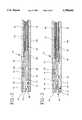
- FIG. 2is a side elevation view in cross-section of a first embodiment of the tip assembly with the rezero apparatus in the measure mode;
- FIG. 3is a view similar to the view shown in FIG. 2 but with the rezero apparatus in the rezero mode;
- FIG. 4is an end view of the tip assembly
- FIG. 5is a side elevation view in cross-section of a second embodiment of the tip assembly with the rezero apparatus in the measure mode;
- FIG. 6is a view similar to the view shown in FIG. 5 but with the rezero apparatus in the rezero mode;
- FIG. 7is a side elevation view in cross-section of a third embodiment of the tip assembly with the rezero apparatus in the measure mode;
- FIG. 8is a view similar to the view shown in FIG. 7 but with the rezero apparatus in the rezero mode;
- FIG. 9is a side elevation view in cross-section of a fourth embodiment of the tip assembly with the rezero apparatus in the rezero mode;
- FIG. 10is a view similar to the view shown in FIG. 9 but with the rezero apparatus in the measure mode.
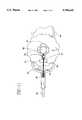
- FIG. 11is a top plan view partially in section of the proximal actuator assembly for the rezero apparatus of this invention.
- the in vivo rezero apparatus for a pressure transducer of this inventionincludes a tip assembly 10, a proximal actuator assembly 50 and a tube 90 that connects tip assembly 10 with proximal actuator assembly 50.
- the pressure transducer 20 used in this deviceis a solid-state, silicon device employing a Wheat stone Bridge circuit configuration. It is a differential pressure device. The difference between the pressure seen at one side of pressure transducer 20 and that seen at the other side is used to determine the pressure in the environment being monitored. Atmospheric pressure is typically used as the reference for physiologic pressure measurements. Thus, one side of pressure transducer 20 must be exposed to physiologic pressure while the other side is vented to atmospheric pressure. In order to rezero pressure transducer 20, both sides of pressure transducer 20 must be exposed to atmospheric pressure or, because it is a differential pressure device, to the same pressure.
- Tip assembly 10which houses pressure transducer 20, has two lumens therein. It can have a bilumen configuration.
- tip assembly 10is formed from a tube 11 within a sleeve 15.
- Tube 11 and sleeve 15are non-concentric and preferably tube 11 abuts sleeve 15 as shown in FIG. 4.
- Tube 11defines a lumen 12, which preferably has a circular cross-section.
- Tube 11is preferably formed from ceramic, metal or polymer and is chosen for its structural as well as its non-magnetic properties.
- Sleeve 15is a polymer extrusion or non-magnetic alloy and is adhered to tube 11 with an adhesive.
- silicone adhesiveis used. The adhesive is applied between tube 11 and sleeve 15 to form a distal wall 16 that occludes the distal end of the lumen 19 formed between tube 11 and sleeve 15.
- An opening 14is located in tube 11 placing lumen 19 and lumen 12 in communication.
- Pressure transducer 20is located over opening 14 and is fixed to tube 11 with an adhesive.
- Preferably silicone adhesiveis used.
- Another opening 17, distal to first opening 14,extends through tube 11 and sleeve 15 at a location where tube 11 and sleeve 15 are in abutting relationship so that lumen 12 is in communication with the exterior of sleeve 15.
- Physiologic pressureis communicated through opening 17 into lumen 12 and through opening 14 to one side of transducer 20.
- FIGS. 2 and 3only one side of pressure transducer 20 is ever exposed to physiologic pressure. This pressure path is explained above.
- the other side of pressure transducer 20is always exposed to atmospheric pressure via lumen 19 between sleeve 15 and tube 11. Lumen 19 is vented to atmospheric pressure through a second opening 18 formed in tube 11 into lumen 12. Lumen 12 communicates with lumen 91 of tube 90 through adapter tube 96.
- Adapter tube 96is bonded to tube 11 and tube 90 to attach tip assembly 10 to tube 90.
- the atmospheric pressure pathcontinues proximally through lumen 91 of catheter 90 and out through opening 59 in actuator assembly 50.
- a movable seal assembly 30 located in lumen 12is used to expose one side of pressure transducer 20 to either atmospheric pressure or physiologic pressure.
- the seal assembly 30includes two seals 31, 32 formed from a rigid tube made from a non-magnetic alloy or polymer, with a coating of silicone over the outer diameter. The silicone material is applied in an even thickness to form an interference seal with lumen 12 of tube 11. Two seals 31, 32 are attached to actuator rod 33 at a fixed distance by an epoxy or other adhesive.
- seal assembly 30is positioned such that distal seal 31 is distal of opening 17 and proximal seal 32 is between opening 14 and opening 18.
- opening 14 and opening 17are in communication and provide an unobstructed path for the physiologic pressure to reach pressure transducer 20.
- the pressure pathis through opening 17, lumen 12 and opening 14.
- seal assembly 30is moved distally so distal seal 31 is still distal of opening 17 but proximal seal 32 is between opening 17 and opening 14.
- both sides of pressure transducer 20are exposed to atmospheric pressure.
- One side of pressure transducer 20is vented to atmospheric pressure via lumen 19, opening 18, lumen 12, and lumen 91 of catheter tube 90 to opening 59 in actuator assembly 50.
- the other side of pressure transducer 20is vented to atmospheric pressure via opening 14, lumen 12, and lumen 91 of catheter tube 90 to opening 59 in actuator assembly 50.
- both sides of pressure transducer 20can be exposed to physiologic pressure. See FIGS. 5 and 6.
- a sidehole 26is formed in the wall of sleeve 15 over pressure transducer 20 to expose one side of pressure transducer 20 to physiologic pressure.
- seal assembly 30is positioned such that distal seal 31 is distal to opening 17 and proximal seal 32 is between opening 17 and opening 14.
- the other side of pressure transducer 20is vented to atmosphere via opening 14, lumen 12 and lumen 91 of catheter tube 90 to opening 59 in actuator assembly 50.
- the one side of pressure transducer 20is exposed to physiologic pressure via sidehole 26.
- the rezero modesee FIG.
- seal assembly 30is moved proximally so distal seal 31 is still distal of opening 17 but proximal seal 32 is proximal of opening 14.
- the one side of pressure transducer 20is still exposed to physiologic pressure via sidehole 26, while the other side of pressure transducer 20 is exposed to physiologic pressure via opening 17, lumen 12 and opening 14. Since pressure transducer 20 is a differential pressure device, this condition is equivalent to exposing both sides of pressure transducer 20 to atmospheric pressure.
- FIGS. 5 and 6with opening 18, it is to be understood that opening 18 is not necessary to its operation.
- seal assembly 30uses a single seal 31 movable within lumen 12. See FIGS. 7 and 8.
- seal 31is proximal to opening 14 and distal to opening 18.
- the one side of pressure transducer 20is exposed to atmospheric pressure via lumen 19, opening 18, lumen 12 and lumen 91 to opening 59 in actuator assembly 50.
- the other side of pressure transducer 20is exposed to physiologic pressure via opening 14 and lumen 12 through the open distal end of tube 11.
- seal 31is distal to opening 14.
- the one side of pressure transducer 20is exposed to atmospheric pressure as already discussed in connection with the measure mode of this embodiment and the other side of pressure transducer 20 is also exposed to atmospheric pressure via opening 14, lumen 12 and lumen 91 to opening 59 in actuator assembly 50.
- the fourth embodiment of this inventionis similar to the third embodiment except that sidehole 26 in sleeve 15 exposes pressure transducer 20 to physiologic pressure. See FIGS. 9 and 10.
- seal 31is distal of opening 14.
- the one side of pressure transducer 20is exposed to physiologic pressure via sidehole 26 and the other side of pressure transducer 20 is exposed to atmospheric pressure via opening 14, lumen 12 and lumen 91 to opening 59 in actuator assembly 50.
- seal 31is moved proximal to opening 14.
- the one side of pressure transducer 20is still exposed to physiologic pressure as discussed above.
- pressure transducer 20is also exposed to physiologic pressure via opening 14, lumen 12 and the open distal end of tube 11. Since pressure transducer 20 is a differential pressure device, this condition is equivalent to exposing both sides of pressure transducer 20 to atmospheric pressure.
- tip assembly 10is connected to the distal end of tube 90.
- Tube 90is preferably formed from a silicone elastomer and defines a single lumen 91 therethrough.
- Adapter tube 96extends proximally of tip assembly 10 and is bonded within lumen 91 of tube 90.
- Adapter tube 96is preferably formed from a non-magnetic alloy.
- Lumen 91houses actuator rod 36, actuator sleeve 35, carrier tube 95 and provides an atmospheric pressure path from tip assembly 10 to actuator assembly 50.
- Carrier tube 95is preferably a polymer extrusion and carries conductor wires (not shown) from pressure transducer 20 to the proximal end of the device for connection to a standard hospital monitor (not shown).
- Actuator sleeve 35is preferably a wound non-magnetic alloy and houses actuator rod 36.
- Actuator rod 36is preferably formed from a highly elastic non-magnetic alloy and is attached to seal assembly 30 at its distal end. The distal end of actuator sleeve 35 is terminated within adapter tube 96.
- the proximal end of tube 90is connected to actuator assembly 50.
- actuator assembly 50Preferably a silicone adhesive is used. See FIG. 11.
- Lumen 91is vented to atmosphere via opening 59 in actuator assembly 50.
- Actuator sleeve 35extends through tube 90 into a cut out portion 65 in the actuator housing 60.
- Actuator rod 36extends out of actuator sleeve 35 into cut out portion 65.
- the proximal end of actuator rod 36includes an enlarged flange 33. Cut out portion 65 defines a distal shoulder 66 therein.
- a spring 70is located around actuator rod 36 between shoulder 66 and flange 33 to bias actuator rod 36 toward the proximal end of the device.
- An actuator knob 80 having a cam 81 located about its axisis connected to actuator housing 60.
- Cam 81is located in abutting relationship to flange 33 of actuator rod 36.
- Cam 81is configured to move flange 33 and thus actuator rod 36 distally against the force of spring 70 when actuator knob 80 is rotated.
- spring 70forces flange 33 and thus actuator rod 36 proximally to follow the contour of cam 81.
- actuator rod 36 and thus seal assembly 30can be moved proximally or distally the appropriate distance to place the device either in the pressure measurement mode or the rezero mode.
- an apparatus for use with an in vivo pressure transduceris provided that will allow the pressure transducer to be rezeroed in vivo.
Landscapes
- Health & Medical Sciences (AREA)
- Life Sciences & Earth Sciences (AREA)
- Molecular Biology (AREA)
- Heart & Thoracic Surgery (AREA)
- Physics & Mathematics (AREA)
- Veterinary Medicine (AREA)
- Biophysics (AREA)
- Pathology (AREA)
- Engineering & Computer Science (AREA)
- Animal Behavior & Ethology (AREA)
- Surgery (AREA)
- Medical Informatics (AREA)
- Public Health (AREA)
- Cardiology (AREA)
- Biomedical Technology (AREA)
- General Health & Medical Sciences (AREA)
- Physiology (AREA)
- Vascular Medicine (AREA)
- Neurosurgery (AREA)
- Hematology (AREA)
- Measuring And Recording Apparatus For Diagnosis (AREA)
- Measuring Fluid Pressure (AREA)
- Surgical Instruments (AREA)
- Measurement Of The Respiration, Hearing Ability, Form, And Blood Characteristics Of Living Organisms (AREA)
- Measuring Pulse, Heart Rate, Blood Pressure Or Blood Flow (AREA)
Abstract
Description
Claims (37)
Priority Applications (4)
| Application Number | Priority Date | Filing Date | Title |
|---|---|---|---|
| US08/492,175US5788642A (en) | 1995-06-19 | 1995-06-19 | In vivo rezero apparatus for a pressure transducer |
| CA002176429ACA2176429A1 (en) | 1995-06-19 | 1996-05-13 | In vivo rezero apparatus for a pressure transducer |
| EP96303650AEP0749721A1 (en) | 1995-06-19 | 1996-05-22 | In vivo rezero apparatus for a pressure transducer |
| JP8157037AJP2709297B2 (en) | 1995-06-19 | 1996-06-18 | In vivo zero-point readjuster for pressure transducers |
Applications Claiming Priority (1)
| Application Number | Priority Date | Filing Date | Title |
|---|---|---|---|
| US08/492,175US5788642A (en) | 1995-06-19 | 1995-06-19 | In vivo rezero apparatus for a pressure transducer |
Publications (1)
| Publication Number | Publication Date |
|---|---|
| US5788642Atrue US5788642A (en) | 1998-08-04 |
Family
ID=23955238
Family Applications (1)
| Application Number | Title | Priority Date | Filing Date |
|---|---|---|---|
| US08/492,175Expired - LifetimeUS5788642A (en) | 1995-06-19 | 1995-06-19 | In vivo rezero apparatus for a pressure transducer |
Country Status (4)
| Country | Link |
|---|---|
| US (1) | US5788642A (en) |
| EP (1) | EP0749721A1 (en) |
| JP (1) | JP2709297B2 (en) |
| CA (1) | CA2176429A1 (en) |
Cited By (10)
| Publication number | Priority date | Publication date | Assignee | Title |
|---|---|---|---|---|
| US6120457A (en)* | 1997-07-02 | 2000-09-19 | Johnson & Johnson Professional, Inc. | In vivo zeroing of catheter pressure sensor |
| US20030131569A1 (en)* | 2002-01-02 | 2003-07-17 | Playtex Products, Inc. | Odor control cassette |
| US20040019285A1 (en)* | 2002-05-14 | 2004-01-29 | Neal Eigler | Apparatus for minimally invasive calibration of implanted pressure transducers |
| US20070027393A1 (en)* | 2005-08-01 | 2007-02-01 | Datascope Investment Corp. | Calibration of in vivo blood pressure sensors |
| US8287495B2 (en) | 2009-07-30 | 2012-10-16 | Tandem Diabetes Care, Inc. | Infusion pump system with disposable cartridge having pressure venting and pressure feedback |
| US20130030262A1 (en)* | 2011-03-07 | 2013-01-31 | Theranova, Llc | Sensing foley catheter |
| CN107184191A (en)* | 2017-06-29 | 2017-09-22 | 长飞光纤光缆股份有限公司 | A kind of miniature insertion type probe |
| US9962486B2 (en) | 2013-03-14 | 2018-05-08 | Tandem Diabetes Care, Inc. | System and method for detecting occlusions in an infusion pump |
| US10258736B2 (en) | 2012-05-17 | 2019-04-16 | Tandem Diabetes Care, Inc. | Systems including vial adapter for fluid transfer |
| US11793409B2 (en)* | 2016-09-30 | 2023-10-24 | Isar-M Gmbh | System for the early detection of postoperative bleeding |
Families Citing this family (1)
| Publication number | Priority date | Publication date | Assignee | Title |
|---|---|---|---|---|
| CN107458282A (en)* | 2016-06-02 | 2017-12-12 | 宝沃汽车(中国)有限公司 | A kind of movable table of seat and there is its seat and vehicle |
Citations (7)
| Publication number | Priority date | Publication date | Assignee | Title |
|---|---|---|---|---|
| US4901735A (en)* | 1988-10-04 | 1990-02-20 | Peter Von Berg Extrakorporale Systeme - Medizintechnik Gmbh | Pressure meter catheter with in-situ zero setting |
| WO1990011717A1 (en)* | 1989-03-31 | 1990-10-18 | Utah Medical Products, Inc. | Apparatus for measuring pressure within body cavity |
| US5050297A (en)* | 1989-09-21 | 1991-09-24 | Becton, Dickinson And Company | Method for assembly of a directly exposed catheter sensor on a support tip |
| EP0492837A1 (en)* | 1990-12-03 | 1992-07-01 | Becton, Dickinson and Company | Apparatus for carrying a sensor in a connector for a catheter adapter |
| US5133358A (en)* | 1990-09-07 | 1992-07-28 | Becton, Dickinson And Company | Apparatus for rezeroing an in vivo pressure sensor and method for rezeroing |
| US5203340A (en)* | 1990-09-07 | 1993-04-20 | Becton, Dickinson And Company | Apparatus for rezeroing an in vivo pressure sensor and method for rezeroing |
| US5437284A (en)* | 1993-12-30 | 1995-08-01 | Camino Laboratories, Inc. | System and method for in vivo calibration of a sensor |
- 1995
- 1995-06-19USUS08/492,175patent/US5788642A/ennot_activeExpired - Lifetime
- 1996
- 1996-05-13CACA002176429Apatent/CA2176429A1/ennot_activeAbandoned
- 1996-05-22EPEP96303650Apatent/EP0749721A1/ennot_activeWithdrawn
- 1996-06-18JPJP8157037Apatent/JP2709297B2/ennot_activeExpired - Fee Related
Patent Citations (7)
| Publication number | Priority date | Publication date | Assignee | Title |
|---|---|---|---|---|
| US4901735A (en)* | 1988-10-04 | 1990-02-20 | Peter Von Berg Extrakorporale Systeme - Medizintechnik Gmbh | Pressure meter catheter with in-situ zero setting |
| WO1990011717A1 (en)* | 1989-03-31 | 1990-10-18 | Utah Medical Products, Inc. | Apparatus for measuring pressure within body cavity |
| US5050297A (en)* | 1989-09-21 | 1991-09-24 | Becton, Dickinson And Company | Method for assembly of a directly exposed catheter sensor on a support tip |
| US5133358A (en)* | 1990-09-07 | 1992-07-28 | Becton, Dickinson And Company | Apparatus for rezeroing an in vivo pressure sensor and method for rezeroing |
| US5203340A (en)* | 1990-09-07 | 1993-04-20 | Becton, Dickinson And Company | Apparatus for rezeroing an in vivo pressure sensor and method for rezeroing |
| EP0492837A1 (en)* | 1990-12-03 | 1992-07-01 | Becton, Dickinson and Company | Apparatus for carrying a sensor in a connector for a catheter adapter |
| US5437284A (en)* | 1993-12-30 | 1995-08-01 | Camino Laboratories, Inc. | System and method for in vivo calibration of a sensor |
Non-Patent Citations (5)
| Title |
|---|
| A Complete ICP System For Parenchymal, Subdural or Ventricular Monitoring brochure by Camino Laboratories, 5955 Pacific Center Blvd., San Diego, CA.* |
| Codman ICP Monitoring System brochure by Johnson & Johnson, Raynham, MA.* |
| ICP Monitoring System brochure by Steritek, 106 McLean Blvd., Paterson, NJ.* |
| OPX Innerspace device brochure by InnerSpace Medical, 1923 S.E. Main Stree, Irvine, CA.* |
| Princeton/LADD ICP Monitor brochure by Princeton Medical Corp., 225 Lowell Road, Hudson, NH.* |
Cited By (32)
| Publication number | Priority date | Publication date | Assignee | Title |
|---|---|---|---|---|
| US6120457A (en)* | 1997-07-02 | 2000-09-19 | Johnson & Johnson Professional, Inc. | In vivo zeroing of catheter pressure sensor |
| US20030131569A1 (en)* | 2002-01-02 | 2003-07-17 | Playtex Products, Inc. | Odor control cassette |
| US20040019285A1 (en)* | 2002-05-14 | 2004-01-29 | Neal Eigler | Apparatus for minimally invasive calibration of implanted pressure transducers |
| US20040106874A1 (en)* | 2002-05-14 | 2004-06-03 | Neal Eigler | Method for minimally invasive calibration of implanted pressure transducers |
| US7195594B2 (en) | 2002-05-14 | 2007-03-27 | Pacesetter, Inc. | Method for minimally invasive calibration of implanted pressure transducers |
| US7862513B2 (en) | 2002-05-14 | 2011-01-04 | Pacesetter, Inc. | Apparatus for minimally invasive calibration of implanted pressure transducers |
| US20070027393A1 (en)* | 2005-08-01 | 2007-02-01 | Datascope Investment Corp. | Calibration of in vivo blood pressure sensors |
| WO2007016513A3 (en)* | 2005-08-01 | 2007-04-12 | Datascope Corp | Calibration of in vivo blood pressure sensors |
| US7771362B2 (en) | 2005-08-01 | 2010-08-10 | Datascope Investment Corp. | Calibration of in vivo blood pressure sensors |
| US20100312126A1 (en)* | 2005-08-01 | 2010-12-09 | Datascope Investment Corp. | Calibration of in vivo blood pressure sensors |
| US8133184B2 (en)* | 2005-08-01 | 2012-03-13 | Datascope Investment Corp. | Calibration of in vivo blood pressure sensors |
| US8926561B2 (en) | 2009-07-30 | 2015-01-06 | Tandem Diabetes Care, Inc. | Infusion pump system with disposable cartridge having pressure venting and pressure feedback |
| US12144964B2 (en) | 2009-07-30 | 2024-11-19 | Tandem Diabetes Care, Inc | Infusion pump system with disposable cartridge having pressure venting and pressure feedback |
| US11285263B2 (en) | 2009-07-30 | 2022-03-29 | Tandem Diabetes Care, Inc. | Infusion pump systems and methods |
| US11135362B2 (en) | 2009-07-30 | 2021-10-05 | Tandem Diabetes Care, Inc. | Infusion pump systems and methods |
| US8758323B2 (en) | 2009-07-30 | 2014-06-24 | Tandem Diabetes Care, Inc. | Infusion pump system with disposable cartridge having pressure venting and pressure feedback |
| US8287495B2 (en) | 2009-07-30 | 2012-10-16 | Tandem Diabetes Care, Inc. | Infusion pump system with disposable cartridge having pressure venting and pressure feedback |
| US9211377B2 (en) | 2009-07-30 | 2015-12-15 | Tandem Diabetes Care, Inc. | Infusion pump system with disposable cartridge having pressure venting and pressure feedback |
| US8298184B2 (en) | 2009-07-30 | 2012-10-30 | Tandem Diabetes Care, Inc. | Infusion pump system with disposable cartridge having pressure venting and pressure feedback |
| US12042627B2 (en) | 2009-07-30 | 2024-07-23 | Tandem Diabetes Care, Inc. | Infusion pump systems and methods |
| US11883174B2 (en) | 2011-03-07 | 2024-01-30 | Potrero Medical, Inc. | Sensing foley catheter |
| US9662058B2 (en)* | 2011-03-07 | 2017-05-30 | Potrero Medical, Inc. | Sensing Foley catheter |
| US9655555B2 (en)* | 2011-03-07 | 2017-05-23 | Potrero Medical, Inc. | Sensing foley catheter |
| US10952659B2 (en) | 2011-03-07 | 2021-03-23 | Potrero Medical, Inc. | Sensing Foley catheter |
| US20130066166A1 (en)* | 2011-03-07 | 2013-03-14 | Theranova, Llc | Sensing foley catheter |
| US11241179B2 (en) | 2011-03-07 | 2022-02-08 | Theranova, Llc | Method of monitoring health status of a patient |
| US20130030262A1 (en)* | 2011-03-07 | 2013-01-31 | Theranova, Llc | Sensing foley catheter |
| US11963773B2 (en) | 2011-03-07 | 2024-04-23 | Theranova, Llc | Method of monitoring health status of a patient |
| US10258736B2 (en) | 2012-05-17 | 2019-04-16 | Tandem Diabetes Care, Inc. | Systems including vial adapter for fluid transfer |
| US9962486B2 (en) | 2013-03-14 | 2018-05-08 | Tandem Diabetes Care, Inc. | System and method for detecting occlusions in an infusion pump |
| US11793409B2 (en)* | 2016-09-30 | 2023-10-24 | Isar-M Gmbh | System for the early detection of postoperative bleeding |
| CN107184191A (en)* | 2017-06-29 | 2017-09-22 | 长飞光纤光缆股份有限公司 | A kind of miniature insertion type probe |
Also Published As
| Publication number | Publication date |
|---|---|
| EP0749721A1 (en) | 1996-12-27 |
| CA2176429A1 (en) | 1996-12-20 |
| JP2709297B2 (en) | 1998-02-04 |
| JPH095184A (en) | 1997-01-10 |
Similar Documents
| Publication | Publication Date | Title |
|---|---|---|
| JP2736195B2 (en) | Connector for catheter adapter | |
| US5788642A (en) | In vivo rezero apparatus for a pressure transducer | |
| JP3980064B2 (en) | Pressure transducer with disposable dome | |
| US5257630A (en) | Pressure sensing probe with calibration capability | |
| US4901735A (en) | Pressure meter catheter with in-situ zero setting | |
| US5048536A (en) | Tourniquet for regulating applied pressures | |
| JP4423436B2 (en) | Pressure transducer protection valve | |
| US6669648B1 (en) | Continuous non-invasive sphygmomanometer | |
| CA1326968C (en) | Disposable pressure transducer and disposable pressure transducer apparatus | |
| US8343100B2 (en) | Surgical system having a non-invasive flow sensor | |
| EP0078312B1 (en) | Pressure monitoring apparatus | |
| US7654967B2 (en) | Gas column pressure monitoring device | |
| CA2136092A1 (en) | Tubing management system | |
| CA2596724C (en) | Surgical system having a cassette with an acoustic air reflector | |
| EP0611550A1 (en) | Intrauterine pressure catheter system | |
| JPH09501587A (en) | Dual pressure sensing catheter | |
| JPH04269938A (en) | Zero-point readjusting apparatus and method for vital internal pressure sensor | |
| EP0290770B1 (en) | Pressure sensor | |
| MX2007003295A (en) | Surgical system having a cassette with an acoustic coupling. | |
| US4633971A (en) | Stethoscope with high frequency filter | |
| JP2854707B2 (en) | Sphygmomanometer | |
| JPH0638921A (en) | Hard endoscope | |
| JPS648781B2 (en) |
Legal Events
| Date | Code | Title | Description |
|---|---|---|---|
| AS | Assignment | Owner name:BECTON, DICKINSON AND COMPANY, NEW JERSEY Free format text:ASSIGNMENT OF ASSIGNORS INTEREST;ASSIGNORS:HAMATAKE, BRET;KUSTER, ROBERT L.;RICHARDS, STEPHEN L.;REEL/FRAME:007550/0916 Effective date:19950615 | |
| STCF | Information on status: patent grant | Free format text:PATENTED CASE | |
| REMI | Maintenance fee reminder mailed | ||
| FPAY | Fee payment | Year of fee payment:4 | |
| SULP | Surcharge for late payment | ||
| FPAY | Fee payment | Year of fee payment:8 | |
| FPAY | Fee payment | Year of fee payment:12 | |
| AS | Assignment | Owner name:ARGON MEDICAL DEVICES, INC., TEXAS Free format text:ASSIGNMENT OF ASSIGNORS INTEREST;ASSIGNOR:BECTON, DICKINSON AND COMPANY;REEL/FRAME:025137/0185 Effective date:20100930 | |
| AS | Assignment | Owner name:GENERAL ELECTRIC CAPITAL CORPORATION, AS ADMINISTR Free format text:SECURITY AGREEMENT;ASSIGNOR:ARGON MEDICAL DEVICES, INC.;REEL/FRAME:025363/0583 Effective date:20100930 | |
| AS | Assignment | Owner name:GENERAL ELECTRIC CAPITAL CORPORATION, AS ADMINISTR Free format text:SECURITY AGREEMENT;ASSIGNORS:ARGON MEDICAL DEVICES, INC.;LUTHER MEDICAL PRODUCTS, INC.;MANAN MEDICAL PRODUCTS, INC.;AND OTHERS;REEL/FRAME:030208/0278 Effective date:20130412 | |
| AS | Assignment | Owner name:ARGON MEDICAL DEVICES, INC., ILLINOIS Free format text:RELEASE BY SECURED PARTY;ASSIGNOR:GENERAL ELECTRIC CAPITAL CORPORATION, AS ADMINISTRATIVE AGENT;REEL/FRAME:030216/0556 Effective date:20130412 | |
| AS | Assignment | Owner name:HEALTHCARE FINANCIAL SOLUTIONS, LLC, AS ADMINISTRA Free format text:SECOND LIEN PATENT SECURITY AGREEMENT;ASSIGNOR:ARGON MEDICAL DEVICES, INC.;REEL/FRAME:037827/0460 Effective date:20151223 | |
| AS | Assignment | Owner name:ARGON MEDICAL DEVICES, INC., ILLINOIS Free format text:RELEASE BY SECURED PARTY;ASSIGNOR:GENERAL ELECTRIC COMPANY (AS SUCCESSOR IN INTEREST BY MERGER TO GENERAL ELECTRIC CAPITAL CORPORATION), AS ADMINISTRATIVE AGENT;REEL/FRAME:037755/0766 Effective date:20151223 | |
| AS | Assignment | Owner name:ARGON MEDICAL DEVICES, INC., ILLINOIS Free format text:RELEASE OF FIRST LIEN PATENT SECURITY AGREEMENTS RECORDED AT REEL/FRAME 037703/0001, 037702/0592, 037702/0580, AND 037702/0497;ASSIGNOR:HEALTHCARE FINANCIAL SOLUTIONS, LLC, AS ADMINISTRATIVE AGENT;REEL/FRAME:045130/0706 Effective date:20180123 Owner name:MANAN MEDICAL PRODUCTS, INC., ILLINOIS Free format text:RELEASE OF FIRST LIEN PATENT SECURITY AGREEMENTS RECORDED AT REEL/FRAME 037703/0001, 037702/0592, 037702/0580, AND 037702/0497;ASSIGNOR:HEALTHCARE FINANCIAL SOLUTIONS, LLC, AS ADMINISTRATIVE AGENT;REEL/FRAME:045130/0525 Effective date:20180123 Owner name:MEDICAL DEVICE TECHNOLOGIES, INC., ILLINOIS Free format text:RELEASE OF FIRST LIEN PATENT SECURITY AGREEMENTS RECORDED AT REEL/FRAME 037703/0001, 037702/0592, 037702/0580, AND 037702/0497;ASSIGNOR:HEALTHCARE FINANCIAL SOLUTIONS, LLC, AS ADMINISTRATIVE AGENT;REEL/FRAME:045130/0706 Effective date:20180123 Owner name:MANAN MEDICAL PRODUCTS, INC., ILLINOIS Free format text:RELEASE OF FIRST LIEN PATENT SECURITY AGREEMENTS RECORDED AT REEL/FRAME 037703/0001, 037702/0592, 037702/0580, AND 037702/0497;ASSIGNOR:HEALTHCARE FINANCIAL SOLUTIONS, LLC, AS ADMINISTRATIVE AGENT;REEL/FRAME:045130/0706 Effective date:20180123 Owner name:MEDICAL DEVICE TECHNOLOGIES, INC., ILLINOIS Free format text:RELEASE OF FIRST LIEN PATENT SECURITY AGREEMENTS RECORDED AT REEL/FRAME 037703/0001, 037702/0592, 037702/0580, AND 037702/0497;ASSIGNOR:HEALTHCARE FINANCIAL SOLUTIONS, LLC, AS ADMINISTRATIVE AGENT;REEL/FRAME:045130/0525 Effective date:20180123 Owner name:ARGON MEDICAL DEVICES, INC., ILLINOIS Free format text:RELEASE OF FIRST LIEN PATENT SECURITY AGREEMENTS RECORDED AT REEL/FRAME 037703/0001, 037702/0592, 037702/0580, AND 037702/0497;ASSIGNOR:HEALTHCARE FINANCIAL SOLUTIONS, LLC, AS ADMINISTRATIVE AGENT;REEL/FRAME:045130/0525 Effective date:20180123 Owner name:PROMEX TECHNOLOGIES, LLC, ILLINOIS Free format text:RELEASE OF FIRST LIEN PATENT SECURITY AGREEMENTS RECORDED AT REEL/FRAME 037703/0001, 037702/0592, 037702/0580, AND 037702/0497;ASSIGNOR:HEALTHCARE FINANCIAL SOLUTIONS, LLC, AS ADMINISTRATIVE AGENT;REEL/FRAME:045130/0706 Effective date:20180123 Owner name:PROMEX TECHNOLOGIES, LLC, ILLINOIS Free format text:RELEASE OF FIRST LIEN PATENT SECURITY AGREEMENTS RECORDED AT REEL/FRAME 037703/0001, 037702/0592, 037702/0580, AND 037702/0497;ASSIGNOR:HEALTHCARE FINANCIAL SOLUTIONS, LLC, AS ADMINISTRATIVE AGENT;REEL/FRAME:045130/0525 Effective date:20180123 Owner name:LUTHER MEDICAL PRODUCTS, INC., ILLINOIS Free format text:RELEASE OF FIRST LIEN PATENT SECURITY AGREEMENTS RECORDED AT REEL/FRAME 037703/0001, 037702/0592, 037702/0580, AND 037702/0497;ASSIGNOR:HEALTHCARE FINANCIAL SOLUTIONS, LLC, AS ADMINISTRATIVE AGENT;REEL/FRAME:045130/0706 Effective date:20180123 Owner name:MEDICAL DEVICE TECHNOLOGIES, INC., ILLINOIS Free format text:RELEASE OF SECOND LIEN PATENT SECURITY AGREEMENTS RECORDED AT REEL/FRAME 037827/0460, 037827/0526, 037827/0764, AND 037827/0882;ASSIGNOR:HEALTHCARE FINANCIAL SOLUTIONS, LLC, AS ADMINISTRATIVE AGENT;REEL/FRAME:045130/0906 Effective date:20180123 Owner name:ARGON MEDICAL DEVICES, INC., ILLINOIS Free format text:RELEASE OF SECOND LIEN PATENT SECURITY AGREEMENTS RECORDED AT REEL/FRAME 037827/0460, 037827/0526, 037827/0764, AND 037827/0882;ASSIGNOR:HEALTHCARE FINANCIAL SOLUTIONS, LLC, AS ADMINISTRATIVE AGENT;REEL/FRAME:045130/0906 Effective date:20180123 Owner name:PROMEX TECHNOLOGIES, LLC, ILLINOIS Free format text:RELEASE OF SECOND LIEN PATENT SECURITY AGREEMENTS RECORDED AT REEL/FRAME 037827/0460, 037827/0526, 037827/0764, AND 037827/0882;ASSIGNOR:HEALTHCARE FINANCIAL SOLUTIONS, LLC, AS ADMINISTRATIVE AGENT;REEL/FRAME:045130/0906 Effective date:20180123 Owner name:LUTHER MEDICAL PRODUCTS, INC., ILLINOIS Free format text:RELEASE OF SECOND LIEN PATENT SECURITY AGREEMENTS RECORDED AT REEL/FRAME 037827/0460, 037827/0526, 037827/0764, AND 037827/0882;ASSIGNOR:HEALTHCARE FINANCIAL SOLUTIONS, LLC, AS ADMINISTRATIVE AGENT;REEL/FRAME:045130/0906 Effective date:20180123 Owner name:MANAN MEDICAL PRODUCTS, INC., ILLINOIS Free format text:RELEASE OF SECOND LIEN PATENT SECURITY AGREEMENTS RECORDED AT REEL/FRAME 037827/0460, 037827/0526, 037827/0764, AND 037827/0882;ASSIGNOR:HEALTHCARE FINANCIAL SOLUTIONS, LLC, AS ADMINISTRATIVE AGENT;REEL/FRAME:045130/0906 Effective date:20180123 |