US5788614A - Plate-loaded chest press exercise machine and method of exercise - Google Patents
Plate-loaded chest press exercise machine and method of exerciseDownload PDFInfo
- Publication number
- US5788614A US5788614AUS08/401,708US40170895AUS5788614AUS 5788614 AUS5788614 AUS 5788614AUS 40170895 AUS40170895 AUS 40170895AUS 5788614 AUS5788614 AUS 5788614A
- Authority
- US
- United States
- Prior art keywords
- hinge
- arm
- handle
- primary
- arms
- Prior art date
- Legal status (The legal status is an assumption and is not a legal conclusion. Google has not performed a legal analysis and makes no representation as to the accuracy of the status listed.)
- Expired - Lifetime
Links
- 238000000034methodMethods0.000titleclaimsabstractdescription15
- 238000006073displacement reactionMethods0.000claimsabstractdescription8
- 210000003205muscleAnatomy0.000claimsdescription22
- 125000006850spacer groupChemical group0.000claimsdescription6
- 238000012559user support systemMethods0.000abstractdescription3
- 230000007246mechanismEffects0.000description60
- 230000036961partial effectEffects0.000description32
- 230000008261resistance mechanismEffects0.000description20
- 230000003068static effectEffects0.000description11
- 229920001971elastomerPolymers0.000description7
- 230000007423decreaseEffects0.000description5
- 210000001364upper extremityAnatomy0.000description5
- 239000005060rubberSubstances0.000description4
- 239000000806elastomerSubstances0.000description3
- 230000005484gravityEffects0.000description3
- 210000003484anatomyAnatomy0.000description2
- 230000000670limiting effectEffects0.000description2
- 238000004519manufacturing processMethods0.000description2
- 230000003387muscularEffects0.000description2
- 210000002976pectoralis muscleAnatomy0.000description2
- 238000003825pressingMethods0.000description2
- 238000012546transferMethods0.000description2
- 206010003694AtrophyDiseases0.000description1
- 206010016761Flat chestDiseases0.000description1
- 229910000760Hardened steelInorganic materials0.000description1
- 229920000271Kevlar®Polymers0.000description1
- 229910001209Low-carbon steelInorganic materials0.000description1
- 229910000831SteelInorganic materials0.000description1
- 229910001315Tool steelInorganic materials0.000description1
- 208000027418Wounds and injuryDiseases0.000description1
- 230000037444atrophyEffects0.000description1
- 230000002457bidirectional effectEffects0.000description1
- 230000006835compressionEffects0.000description1
- 238000007906compressionMethods0.000description1
- 230000006378damageEffects0.000description1
- 230000007812deficiencyEffects0.000description1
- 238000013461designMethods0.000description1
- 238000011161developmentMethods0.000description1
- 239000013013elastic materialSubstances0.000description1
- 239000004744fabricSubstances0.000description1
- 208000014674injuryDiseases0.000description1
- 238000012423maintenanceMethods0.000description1
- 230000007935neutral effectEffects0.000description1
- 230000008447perceptionEffects0.000description1
- 239000004033plasticSubstances0.000description1
- 229920003023plasticPolymers0.000description1
- 229920000642polymerPolymers0.000description1
- 230000002829reductive effectEffects0.000description1
- 239000012858resilient materialSubstances0.000description1
- 230000000284resting effectEffects0.000description1
- 230000035807sensationEffects0.000description1
- 239000010959steelSubstances0.000description1
- 238000003860storageMethods0.000description1
- 238000001356surgical procedureMethods0.000description1
- 238000003466weldingMethods0.000description1
Images


Classifications
- A—HUMAN NECESSITIES
- A63—SPORTS; GAMES; AMUSEMENTS
- A63B—APPARATUS FOR PHYSICAL TRAINING, GYMNASTICS, SWIMMING, CLIMBING, OR FENCING; BALL GAMES; TRAINING EQUIPMENT
- A63B23/00—Exercising apparatus specially adapted for particular parts of the body
- A63B23/035—Exercising apparatus specially adapted for particular parts of the body for limbs, i.e. upper or lower limbs, e.g. simultaneously
- A63B23/12—Exercising apparatus specially adapted for particular parts of the body for limbs, i.e. upper or lower limbs, e.g. simultaneously for upper limbs or related muscles, e.g. chest, upper back or shoulder muscles
- A63B23/1245—Primarily by articulating the shoulder joint
- A63B23/1254—Rotation about an axis parallel to the longitudinal axis of the body, e.g. butterfly-type exercises
- A—HUMAN NECESSITIES
- A63—SPORTS; GAMES; AMUSEMENTS
- A63B—APPARATUS FOR PHYSICAL TRAINING, GYMNASTICS, SWIMMING, CLIMBING, OR FENCING; BALL GAMES; TRAINING EQUIPMENT
- A63B21/00—Exercising apparatus for developing or strengthening the muscles or joints of the body by working against a counterforce, with or without measuring devices
- A63B21/06—User-manipulated weights
- A63B21/062—User-manipulated weights including guide for vertical or non-vertical weights or array of weights to move against gravity forces
- A63B21/0626—User-manipulated weights including guide for vertical or non-vertical weights or array of weights to move against gravity forces with substantially vertical guiding means
- A63B21/0628—User-manipulated weights including guide for vertical or non-vertical weights or array of weights to move against gravity forces with substantially vertical guiding means for vertical array of weights
- A—HUMAN NECESSITIES
- A63—SPORTS; GAMES; AMUSEMENTS
- A63B—APPARATUS FOR PHYSICAL TRAINING, GYMNASTICS, SWIMMING, CLIMBING, OR FENCING; BALL GAMES; TRAINING EQUIPMENT
- A63B21/00—Exercising apparatus for developing or strengthening the muscles or joints of the body by working against a counterforce, with or without measuring devices
- A63B21/40—Interfaces with the user related to strength training; Details thereof
- A63B21/4027—Specific exercise interfaces
- A63B21/4033—Handles, pedals, bars or platforms
- A63B21/4035—Handles, pedals, bars or platforms for operation by hand
- A—HUMAN NECESSITIES
- A63—SPORTS; GAMES; AMUSEMENTS
- A63B—APPARATUS FOR PHYSICAL TRAINING, GYMNASTICS, SWIMMING, CLIMBING, OR FENCING; BALL GAMES; TRAINING EQUIPMENT
- A63B21/00—Exercising apparatus for developing or strengthening the muscles or joints of the body by working against a counterforce, with or without measuring devices
- A63B21/40—Interfaces with the user related to strength training; Details thereof
- A63B21/4041—Interfaces with the user related to strength training; Details thereof characterised by the movements of the interface
- A63B21/4047—Pivoting movement
- A—HUMAN NECESSITIES
- A63—SPORTS; GAMES; AMUSEMENTS
- A63B—APPARATUS FOR PHYSICAL TRAINING, GYMNASTICS, SWIMMING, CLIMBING, OR FENCING; BALL GAMES; TRAINING EQUIPMENT
- A63B23/00—Exercising apparatus specially adapted for particular parts of the body
- A63B23/035—Exercising apparatus specially adapted for particular parts of the body for limbs, i.e. upper or lower limbs, e.g. simultaneously
- A63B23/03516—For both arms together or both legs together; Aspects related to the co-ordination between right and left side limbs of a user
- A63B23/03525—Supports for both feet or both hands performing simultaneously the same movement, e.g. single pedal or single handle
- A—HUMAN NECESSITIES
- A63—SPORTS; GAMES; AMUSEMENTS
- A63B—APPARATUS FOR PHYSICAL TRAINING, GYMNASTICS, SWIMMING, CLIMBING, OR FENCING; BALL GAMES; TRAINING EQUIPMENT
- A63B23/00—Exercising apparatus specially adapted for particular parts of the body
- A63B23/035—Exercising apparatus specially adapted for particular parts of the body for limbs, i.e. upper or lower limbs, e.g. simultaneously
- A63B23/12—Exercising apparatus specially adapted for particular parts of the body for limbs, i.e. upper or lower limbs, e.g. simultaneously for upper limbs or related muscles, e.g. chest, upper back or shoulder muscles
- A63B23/1209—Involving a bending of elbow and shoulder joints simultaneously
- A—HUMAN NECESSITIES
- A63—SPORTS; GAMES; AMUSEMENTS
- A63B—APPARATUS FOR PHYSICAL TRAINING, GYMNASTICS, SWIMMING, CLIMBING, OR FENCING; BALL GAMES; TRAINING EQUIPMENT
- A63B21/00—Exercising apparatus for developing or strengthening the muscles or joints of the body by working against a counterforce, with or without measuring devices
- A63B21/06—User-manipulated weights
- A63B21/0615—User-manipulated weights pivoting about a fixed horizontal fulcrum
- A—HUMAN NECESSITIES
- A63—SPORTS; GAMES; AMUSEMENTS
- A63B—APPARATUS FOR PHYSICAL TRAINING, GYMNASTICS, SWIMMING, CLIMBING, OR FENCING; BALL GAMES; TRAINING EQUIPMENT
- A63B2208/00—Characteristics or parameters related to the user or player
- A63B2208/02—Characteristics or parameters related to the user or player posture
- A63B2208/0228—Sitting on the buttocks
- A63B2208/0233—Sitting on the buttocks in 90/90 position, like on a chair
- A—HUMAN NECESSITIES
- A63—SPORTS; GAMES; AMUSEMENTS
- A63B—APPARATUS FOR PHYSICAL TRAINING, GYMNASTICS, SWIMMING, CLIMBING, OR FENCING; BALL GAMES; TRAINING EQUIPMENT
- A63B23/00—Exercising apparatus specially adapted for particular parts of the body
- A63B23/035—Exercising apparatus specially adapted for particular parts of the body for limbs, i.e. upper or lower limbs, e.g. simultaneously
- A63B23/12—Exercising apparatus specially adapted for particular parts of the body for limbs, i.e. upper or lower limbs, e.g. simultaneously for upper limbs or related muscles, e.g. chest, upper back or shoulder muscles
- A63B23/1245—Primarily by articulating the shoulder joint
- A63B23/1263—Rotation about an axis passing through both shoulders, e.g. cross-country skiing-type arm movements
- Y—GENERAL TAGGING OF NEW TECHNOLOGICAL DEVELOPMENTS; GENERAL TAGGING OF CROSS-SECTIONAL TECHNOLOGIES SPANNING OVER SEVERAL SECTIONS OF THE IPC; TECHNICAL SUBJECTS COVERED BY FORMER USPC CROSS-REFERENCE ART COLLECTIONS [XRACs] AND DIGESTS
- Y10—TECHNICAL SUBJECTS COVERED BY FORMER USPC
- Y10S—TECHNICAL SUBJECTS COVERED BY FORMER USPC CROSS-REFERENCE ART COLLECTIONS [XRACs] AND DIGESTS
- Y10S482/00—Exercise devices
- Y10S482/908—Adjustable
Definitions
- the inventionrelates generally to the field of exercise and physical rehabilitation equipment and, in particular, to an apparatus and method for exercising the upper torso.
- the muscles of the chestmay be exercised by an exercise known as the chest press.
- the chest pressmay be performed on either a flat, inclined or declined bench.
- the use of such different benchesaffects the region of the chest, e.g., middle, upper, lower, that is most optimally exercised.
- To perform the chest press with a barbellan exerciser lies on his back, extends his arms substantially vertically and grasps a barbell that is typically supported by a frame above the exerciser's head. The exerciser lowers the barbell to his chest, then pushes the barbell upwardly, extending his arms.
- This exercisecan be dangerous as the exerciser may not be able to control the downward motion of the barbell or may not be able to push the barbell off his chest. For this reason, the exerciser should have a partner to spot him.
- the resistance provided by gravityis constant while the strength of the muscles varies over the range of motion. Consequently, the muscles are not fully loaded at each point over the range of motion.
- the handsseek to follow a curved path inwardly as the arms are extended upwardly. This path cannot be followed when using a barbell because the hands are maintained at a fixed distance. This deficiency may be overcome by performing the exercise with dumbells.
- a decline chest press machinein which two independently maneuverable levers are pivotally connected to a frame above a declined seat. Arms extend downwardly and rearwardly from the levers and angled handles are connected to the bottoms of the arms. Each handle is adapted to be grasped by a user supported on the seat and then pressed forwardly and upwardly in an arcuate path along a vertical plane that is described to converge inwardly with respect to the front of the declined seat. Resistance to handle movement is provided by weight plates mounted to the levers.
- the converging pathis achieved by disposing hinges for the levers at an angle of 20° from the perpendicular to a central vertical midplane. As such, the user's hands must follow a preset rate of convergence and divergence during the exercise stroke, regardless of his anatomy. This apparatus does not permit the exerciser to select his own path of motion for the press exercise. Rather, the motion is dictated by the angle of the hinges.
- An upper extremity exercise apparatusis disclosed in U.S. Pat. No. 4,603,856.
- a benchis provided for an user to exercise in a prone or supine position.
- a shaftextends from a ball and socket joint mounted to the side of the bench, and a handle is slidably mounted to the shaft.
- Frictional resistanceis provided both at the ball and socket joint and at the sliding connection between the handle and the shaft. The user exercises by moving the handle against one or both of these resistances.
- this machineWhile providing multiple paths of motion through the range of the ball and socket joint, this machine provides for exercising only one arm at a time, cannot coordinate the motion of two arms, and has the disadvantages associated with frictional resistance such as changing resistance due to heat buildup, and wear. Further, this machine only provides concentric action (i.e., where the muscles contract against a load). No eccentric action (i.e., where muscles extend under a load) is possible with this machine.
- an apparatusfor performing a chest press to exercise the muscles of a user.
- a primary hingeis mounted to a frame.
- a secondary hingeis mounted to the primary hinge.
- An armis mounted to the secondary hinge.
- a handleis mounted to the arm distal to the secondary hinge. The handle is adapted to be grasped and displaced by the user.
- a resistance meanssuch as a weight is attached to the arm at a point offset laterally outward from the handle. Due to the orientation of the two hinges, the handle may be displaced in both a longitudinal direction (upward) and a lateral direction (outward to the sides), as selected by the user. Due to the offset of the resistance means, combined with the orientation of the two hinges, displacement is resisted in both the lateral and longitudinal directions.
- the resistance meansmay include a post attached to the arm for mounting free weight plates.
- a second handle, arm and secondary hingemay be provided for the other hand so that the user may exercise both halves of his body.
- the armsmay be connected such that both handles move the same longitudinal and/or lateral distance.
- a methodfor performing a chest press exercise with an apparatus having an arm pivotally mounted to a frame.
- a userloads a weight plate on a post mounted to the arm and lies on a user support.
- the usergrasps a handle mounted to the arm and pushes the handle upward longitudinally from about chest level, moving the handle longitudinally and laterally as he so chooses.
- the userovercomes resistance to the lateral movement of the handle and resistance to the longitudinal movement of the handle.
- the usermay grasp a second handle with his other hand to exercise both halves of his body.
- the handlesmay be connected such that both handles move the same longitudinal and/or lateral distance.
- FIG. 1is a perspective view of an embodiment of a chest press exercise machine of the present invention in a static rest position
- FIG. 2is a partial perspective view of the hinge portion of the exercise machine of FIG. 1, with the arms partially cut away;
- FIGS. 3A-3Care schematic views of hinge mechanisms for use in the exercise machine of FIG. 1, in a plane IA--IA shown in FIG. 4;
- FIG. 4is a side elevation view of the exercise machine of FIG. 1 with the arms in a rest position;
- FIG. 5is a side elevation view of the exercise machine of FIG. 1 with the arms raised;
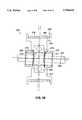
- FIG. 6is plan view of the exercise machine of FIG. 1;
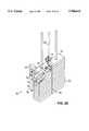
- FIG. 7is a front elevation view of the exercise machine of FIG. 1, with the arms in the static rest position;
- FIG. 8is a partial schematic view of the hinge mechanism and arms of an embodiment of the invention having hinge plates
- FIG. 9is a partial schematic view of the hinge mechanism and arms of an embodiment of the invention having a slider link
- FIG. 10is a partial schematic view of the hinge mechanism and arms of an embodiment of the invention having a cam link
- FIG. 11is a partial schematic view of the hinge mechanism and arms of an embodiment of the invention having variable length links with resistance;
- FIG. 12is a partial schematic view of the hinge mechanism and arms of an embodiment of the invention having a spring pulley linkage
- FIG. 13Ais a front elevational view of a weight stack of an embodiment of the invention.
- FIG. 13Bis a side elevational view of the weight stack of FIG. 13A;
- FIG. 14is a partial schematic view of the hinge mechanism, arms and handles of an embodiment of the invention having incrementally adjustable handle resistance;
- FIG. 14Ais a partial schematic view of the hinge mechanism, arms and handles of an embodiment of the invention having discrete degrees of resistance;
- FIG. 15is a partial schematic view of the hinge mechanism and arms of an embodiment of the invention having incrementally adjustable handle resistance
- FIG. 15Ais a partial schematic view of the hinge mechanism and arms of an embodiment of the invention having discrete levels of resistance.
- FIG. 16is a schematic view of the hinge mechanism of an embodiment of the invention having torsion springs to resist lateral movement;
- FIG. 17is a schematic view of the hinge mechanism, arms and handles of an embodiment of the invention having a pivoting handgrip;
- FIG. 18is a partial schematic view of the hinge mechanism and arms of an embodiment of the invention having large gears
- FIG. 19is a partial schematic view of the hinge mechanism and arms of an embodiment of the invention having a rack and pinion link;
- FIG. 20is a partial schematic view of the hinge mechanism and arms of an embodiment of the invention having a belt and pulley link;
- FIG. 21is a partial schematic view of the hinge mechanism, arms and handles of an embodiment of the invention having outward sliding hand grips;
- FIG. 21Ais a partial schematic end view of the arms and handles of FIG. 21;
- FIG. 21Bis a partial schematic end view of the arms and handles of an embodiment of the invention having angled handle rods;
- FIG. 21Cis a partial schematic end view of the arms and handles of an embodiment of the invention having angled handle rods;
- FIG. 21Dis a partial schematic end view of the arms and handles of an embodiment of the invention having a handle rod resistance mechanism
- FIG. 21Eis a partial schematic end view of the arms and handles of an embodiment of the invention having a handle rod resistance mechanism
- FIG. 21Fis a partial schematic end view of the arms and handles of an embodiment of the invention having a handle rod resistance mechanism
- FIG. 22is a partial schematic view of the hinge mechanism, arms and handles of an embodiment of the invention having inward sliding hand grips;
- FIG. 22Ais a partial schematic end view of the arms and handles of FIG. 22;
- FIG. 22Bis a partial schematic end view of the arms and handles of an embodiment of the invention having angled handle rods;
- FIG. 22Cis a partial schematic end view of the arms and handles of an embodiment of the invention having angled handle rods;
- FIG. 22Dis a partial schematic end view of the arms and handles of an embodiment of the invention having a handle rod resistance mechanism
- FIG. 22Eis a partial schematic end view of the arms and handles of an embodiment of the invention having a handle rod resistance mechanism
- FIG. 22Fis a partial schematic end view of the arms and handles of an embodiment of the invention having a handle rod resistance mechanism
- FIG. 23is a partial schematic view of the hinge mechanism, arms and handles of an embodiment of the invention having sliding handles with cable resistance;
- FIG. 23Ais a partial detail perspective view of an arm and handle of the machine of FIG. 23;
- FIG. 24is a partial schematic view of the hinge mechanism and arms of an embodiment of the invention having a pivoting bar linkage
- FIG. 25is a schematic view of the hinge mechanism of an embodiment of the invention having an adjustable arm angle
- FIG. 26is a cross-sectional view of a self-aligning pulley for use with an exercise machine, including the machine of FIG. 13;
- FIG. 27is a cross sectional view of the pulley of FIG. 26, taken through section XXVII--XXVII;
- FIG. 28is another cross-sectional view of the pulley in the same section as FIG. 26, showing a misaligned frame
- FIG. 29is a perspective view of an incremental weight stack for use with an exercise machine, including the machine of FIG. 13.
- FIG. 1is a perspective view of an embodiment of the chest press machine 1 of this invention in the static rest position.
- the exercise machinehas a frame 10 comprising a front leg 20, a lower brace 22, an upper brace 24, arm support housings 23, a rear brace 26 and a hinge brace 28 (see FIG. 4).
- the framemay further comprise a rear brace support 29.
- the frameis constructed of 2-inch square, 11 gauge steel tubing.
- a bench 12is mounted on, and supported by, the front leg 20 and the upper brace 24 of the frame. The bench 12 should have a width W suitable to comfortably support a user in a stable position during the exercise.
- a foot brace 5is attached to the front leg 20. The foot brace 5 may be used to help stabilize a user during exercise.
- Arms 60are mounted to the frame 10 by a hinge mechanism 50, including a primary hinge 30 and secondary hinges 32 and 34.
- the primary hinge 30is mounted to the frame 10.
- the hinge brace 28 of the framecurves upward at the rear of the frame for mounting the primary hinge 30 (see FIG. 4).
- the primary hingeis disposed perpendicularly to a vertical plane X--X (see FIG. 6) extending through the center of the machine 1.
- the primary hinge 30is disposed behind the back of the bench 12 and fixed atop the hinge brace 28.
- the primary hinge 30 and/or the front end 11 and/or the back end 13 of the bench 12could be vertically adjustable to affect a decline or incline chest press, as well as a flat chest press.
- Handles 61are mounted at the end of the arms 60 distal to the hinge mechanism 50. Other handle positions than that shown in the FIGURES, or a variable position handle such as a pivoting handle, could alternatively be used.
- Posts 62extend outwardly from the arms 60 for mounting weight plates 23 (see FIG. 6).
- Spacers 64are mounted to the posts 62 proximate to the arms 60.
- the userexercises by pushing handles 61 upward from a rest position, overcoming the resistance of gravity on the weight plates.
- other mechanisms for providing resistancesuch as a friction, springs, elastic bands, pneumatic or electromagnetic resistance, or an air resistance fan could be employed (either alone or in combination) and still practice the invention.
- a weight stackcould be operably engaged to the arms 60 to resist the movement of handles 61.
- Each end of the upper brace 24 and the lower brace 22is attached to one of the arm support housings 23.
- the arms 60rest on static supports 21 which are positioned, one on each side of the bench, about mid-way between an edge of the bench and the arm support housing 23.
- the static supports 21support the arms 60 at a point along the arms about mid-way between the primary hinge 30 and the posts 62.
- a rubber or elastomer bumper 59is mounted to the arm at this point to protect the arm.
- the static supports 21are sized so that when the arms 60 are resting on the static supports, the arms maintain an approximately horizontal orientation.
- each arm support housing 23Within each arm support housing 23 is a telescoping rod 16 having holes 17 which terminates in an arm support 18 (see FIG. 7). A pin 19 is received by the holes 17 in the telescoping rod 16 to set the arm support 18 at a desired height.
- a usersets each arm support 18 to a desired height as discussed above, and then places each arm 60 on an arm support in an exercise rest position. Weights may then be placed on the posts 62. In this manner, users having different chest sizes, arm length and flexibility may set the arms 60 at a comfortable level relative to their chest.
- the arms 60may remain on the static supports 21 (the static rest position) while the arm supports 18 are adjusted. In this manner, the user does not have to hold the arm 60 with one hand and adjust the arm support 18 with the other hand.
- the front leg 20 and the arm support housings 23are supported at their lower ends by plate members 3 and 4, respectively.
- bolt holesare provided in the plate members to allow the exercise machine 1 to be secured during transit or for normal use.
- FIG. 2is a perspective view of the hinge mechanism 50 with the arms 60 partially cut away.
- the primary bearing tube 31is rotatable about a primary axis 46 which axis is disposed perpendicular to the vertical plane X--X (FIG. 6) through the center of the machine.
- Brackets 47are rigidly mounted to the primary bearing tube 31, such as by welding.
- the secondary hinges 32 and 34are rotatably mounted to the brackets.
- the secondary hingesinclude the secondary bearing tubes 33 and 35 mounted to sealed bearings (not shown), such as model #87503 metric bearings manufactured by Fafnir, or an equivalent.
- the secondary bearing tubesare rotatable about secondary axes 48 and 49.
- the secondary hinge axes 48 and 49are skew to the primary hinge axis 46; in other words, the secondary hinge axes are not parallel to the primary hinge axis.
- the arms 60are rigidly attached to the secondary bearing tubes 33 and 35 approximately perpendicular to the secondary hinge axes.
- FIGS. 3A, 3B and 3Cwhich are schematic views of the primary hinge and secondary hinges in plane IA--IA (see FIG. 4), the secondary hinges are disposed at an angle A with respect to the primary hinge.
- the preferred angle Ais 115°, as shown in FIG. 3C and explained below.
- the hinge mechanism 50operates to utilize these forces to create a lateral (outward) component of resistance.
- the combination of lateral and longitudinal resistanceincreases the effectiveness of the chest press exercise and provides feedback to the user that encourages symmetrical exercise paths of the right and left hands.
- FIGS. 3A, 3B and 3Care schematic views of hinge mechanism 50 showing the secondary hinge angle A.
- a secondary hinge angle A other than 90°as shown in FIGS. 3A and 3C, asymmetry between the position of the user's right and left hands during an exercise stroke will cause the user to feel asymmetric feedback from the machine.
- the typical userwill naturally seek to distribute the load equivalently between the left and right sides. Consequently, the secondary hinge angle of more or less than 90° encourages the user to move his hands symmetrically.
- the more the secondary hinge angle A diverges from 90°the more the user is encouraged to perform the exercise symmetrically.
- the hinge mechanism 50can make the exercise machine feel "stable" as perceived by a user. It has been found that in using a machine with a hinge angle A of 90°, the user perceives that the exercise stroke is unstable because lateral hand movement is unresisted. This sensation is more pronounced in exercises requiring pushing, such as the chest press exercise of the present exercise machine, than in pulling exercises. A machine with a hinge angle A other than 90° feels more stable to a user because it resists lateral movement and encourages a symmetrical stroke. The perception of stability increases as angle A diverges from 90°.
- the preferred secondary hinge angle of 115°(as shown in FIG. 3C) has been found by experimentation to produce the most comfortable chest press exercise stroke.
- the relationship of lateral resistance to longitudinal resistance at this angleseems to provide an effective exercise for the muscles of the chest.
- sufficient lateral resistanceis provided so that a user perceives the chest press exercise as stable.
- Other secondary hinge anglescould be selected for a chest press apparatus based on the comfort, stability, muscular development or exercise goals of a particular group of users to emphasize the longitudinal or lateral resistance to the exercise.
- FIG. 4is a side elevation view of the chest press exercise apparatus in the rest position without weight plates mounted on the posts 62.
- the post 62In the rest position, the post 62 is at about the level of the primary hinge 30. As the handle 61 is raised, the movement of post 62, and any weight plates mounted on it, approximates an arc about the primary hinge 30. Near the rest position, the weight of the plate 23 acts in a direction opposite the path of the weight plates, providing a maximum resistance in the exercise stroke. As the arms move upward through an angle ⁇ (FIG. 5), the component of the weight acting to resist arm motion decreases.
- FIG. 5is a side elevation view of the chest press exercise apparatus without weight plates mounted on the posts 62.
- the armsare in an elevated position, having lifted the post 62 and any weight thereon to an angle ⁇ above the horizontal.
- the secondary hingeshave rotated upward about the primary hinge.
- FIG. 6is a plan view of the chest press exercise machine of the invention in the rest position with a weight plate 23 mounted to one of the posts 62.
- An arm strap 53connects the arms 60 to limit outward travel of the arms during the exercise stroke and in the rest position.
- the arm strapis preferably KEVLAR® fabric, although other high-strength tethers could be used.
- the strapis held on the arms by a pressure plate 54 that clamps the strap to the arms.
- the strapis positioned on the arms 60 so that it remains behind the user's head.
- other mechanisms for limiting arm travelsuch as mechanical stops attached to the secondary bearing tubes, could be used and still practice the invention.
- a means for limiting the inward travel of the arms 60 during the exercise strokeis used.
- Such a meansincludes, without limitation, mechanical stops attached to the secondary bearing tubes.
- FIG. 7is a front elevation view of the apparatus of FIG. 1 in the rest position.
- the weight posts 62are inclined upward approximately 25° in order to safely retain the weight plates 23.
- the arm supports 18are adjusted to a desired height while the arms are in the static rest position, and the arms 60 are moved from the static supports 21 to the arm supports 18.
- Weight platesare mounted on the posts 62 corresponding to the resistance desired. Preferably, the same weight is placed on each one of the posts.
- the userlies face up on the bench, orienting himself so that his shoulders are approximately in line with the handles 61. The user then grasps the handles at a selected position.
- a narrower gripi.e., hands relatively closer to the centerline of the bench, will result in an increasing contribution by the tricep muscles in performing the exercise.
- a wider gripi.e., hands closest to the arms 60, will result in an increasing contribution by the pectoral muscles in performing the exercise.
- the userpushes upwardly.
- the movement of the handlescauses rotation of the arms 60, the secondary bearings 32 and 34 and the brackets 47 about the primary bearing 30.
- the armrotates, it lifts the posts 62 and weights 23.
- the userthen returns the handles to the initial position, thereby lowering the weight plates.
- the userpushes the handles upward (concentric action)
- heovercomes the resistance provided by the weight.
- the user returns the handleshe succumbs to the resistance provided by the weight.
- a usermay choose to emulate a traditional chest press exercise by grasping the handles 61 in the rest position (a wide hand width) and pressing directly upward while maintaining his hands at a constant width.
- the arm strap 53 between the arms 60remains taut, and there is no lateral movement of the handles.
- the secondary bearing tubes 33 and 35are not caused to rotate with respect to the brackets 47. Rather, only the primary bearing tube 31 rotates and the handles follow a path similar to that of traditional machines.
- the usermay choose a chest press exercise with an inward lateral component of motion.
- the userbegins the exercise stroke by grasping the handles 61 at the rest position, pressing upward at the beginning of the stroke and bringing the handles together in an arcuate path at the end of the stroke.
- the userencounters resistance in both the longitudinal and lateral components of the concentric portion (i.e., where the muscles contract against the load) of the stroke. In a traditional machine, this would not be possible.
- the hinge mechanism 50allows such movement.
- the outward offset R of the weight plates to the handlescauses the hinge mechanism 50 to resist the lateral component of movement.
- the axis A--Awhich passes through the user's grip on the handle 61, can be moved by the user by moving his grip on the handle. This, in turn, increases or decreases the offset R, which in turn affects the resistance to the lateral component of movement.
- the usercan therefore select, to some extent, the ratio of lateral to longitudinal resistance by his grip placement on the handle 61.
- the usercannot "lock out” his elbows at the end of the exercise stroke to transfer the load from the muscular system to the skeletal system, as is possible on traditional machines and free weights.
- the lateral component of the resistancecontinues to oppose the chest muscles even when the user's elbows are straightened.
- the hinge mechanism 50permits movement of the handles 61 upward (i.e., longitudinally) and inward (i.e., laterally) in a relationship selected by the user. Consequently, the user can grasp the handles and push upward and inward in the natural arcuate path.
- the usercan select another path to give the muscles a different workout. For example, the user may wish to push directly upward and then move directly downward, emulating the purely longitudinal motion of a traditional chest press. The user may instead choose to press his hands directly upward, and then, at the end of the stroke, move his hands in latitudinally while his arms are fully extended. The user can even chose a "figure eight" path, moving his hands in, out, in and out again during the exercise stroke. Any combination of such movements can be accomplished with the machine of the present invention.
- the userhas flexibility in how he exercises the muscles of his chest.
- the resistance overcome by the particular muscle groupis determined, in part, by the selected path of the hands and the secondary hinge angle A.
- the offset R and the secondary hinge angle Aare selected to present a combination of lateral resistance and longitudinal resistance that feels comfortable or natural to a typical user moving his hands in an arcuate path. Consequently, the user defines, in part, the resistance profile by his path selection.
- the double hinge mechanism 50in combination with the weight placement on the arms thus provides a fundamental advance over existing exercise machines by establishing a ratio of lateral to longitudinal resistance while encouraging left-to-right hand symmetry in the exercise stroke and allowing the user to select the path of the stroke and the muscle group emphasized.
- the hinge mechanism 50encourages symmetrical movement of the handles 61. Such symmetrical movement, however, is not required. The user can move his hands through different paths during the same exercise stroke. While this configuration is currently the preferred embodiment of the invention, it may be advantageous in some situations to further couple the motion of the arms, as is done in several of the following additional embodiments.
- FIG. 8is a schematic plan view of the hinge mechanism 80 and arms 81 of another embodiment of the invention.
- the secondary hinges 82are shown disposed perpendicular to the primary hinge 83, although they may be oriented at other angles.
- Flanges 84are pivotally mounted to each arm, such as by piano hinges 85.
- the flanges 84are rotatably mounted to each other, such as by a knuckle joint 86.
- the arms and flangesconstrain the knuckle joint to move within the plane of symmetry S--S between the arms. Since the linkage formed by the primary bearing tube 87, the arms and the flanges is symmetrical, the arms must translate the same amount laterally. Consequently, the arms (and thus the handles) are forced to move symmetrically.
- the hinges, flanges and knuckle jointmay be constructed of a resilient material such as plastic, elastomer or rubber.
- the knuckle jointmay be a deformable rubber connector, or the hinges, flanges and knuckle may be a one-piece polymer part with reduced cross sections in the areas requiring flexure. Such embodiments encourage symmetric exercise strokes while permitting some left-to-right asymmetry.
- FIG. 9is a schematic plan view of the hinge mechanism 90 and arms 91 of another embodiment of the invention. Again, the arms are operably engaged such that they must move symmetrically in the lateral direction.
- the secondary 92 hingesare again shown disposed perpendicular to the primary hinge 93, although other angles of attachment are possible.
- a slider rod 94is fixedly mounted to the primary hinge 93.
- a slider ring 95is mounted to the slider rod 94 and adapted to be displaceable along its length.
- Links 96are pivotally mounted to the slider ring and to each arm 91. Consequently, as the arms are displaced laterally, the slider ring is caused to move along the slider rod. Due to their mutual connection to the slider ring, both arms are caused to move symmetrically about the secondary hinges.
- FIG. 10is a schematic plan view of the hinge mechanism 100 and arms 101 of another embodiment of the present invention.
- the secondary hinges 102are shown mounted perpendicularly to the primary hinge 103, although other attachment angles are possible.
- a barrel cam 104 having mirrored, grooved profiles 105is mounted to the primary bearing tube 108 equidistant from both secondary hinges 102.
- the barrel camis mounted for rotational movement.
- a rigid link 106 with a cam follower 107is pivotally mounted to each arm. As an arm is moved outward, the barrel cam is forced to rotate about its axis, causing the other rigid link to force the other arm to move the same lateral distance.
- FIG. 11is a schematic plan view of the hinge mechanism 110 and arms 111 of another embodiment of the invention.
- the secondary hinges 112are shown mounted perpendicularly to the primary hinge 113, although other attachment angles are possible.
- An anchor 114is rigidly mounted to the primary hinge between the secondary hinges 112.
- a variable length link 115engages each arm 111 to the anchor.
- a resistance mechanism 116such as a pneumatic, hydraulic, spring, elastic band, electrical or magnetic resistance, is operably engaged to the link 115 to resist any change is length. Consequently, the mechanism provides resistance to lateral movement of the arms 111 during the exercise stroke. Also, the resistance mechanism discourages quick, lateral movement of the arms.
- the mechanism 110thus provides resistance to lateral movement both inward and outward, while encouraging a smooth stroke.
- FIG. 12is a schematic plan view of the hinge mechanism 120 and arms 121 of another embodiment of the invention.
- the secondary hinges 122are shown mounted perpendicular to the primary hinge 123. However, other orientations are possible.
- Branches 124are fixedly mounted to the primary bearing tube 129.
- a pulley 125is mounted on each branch and disposed in the same plane as its respective arm.
- Cables or belts 126are attached to the arms 121, extend over the pulleys 125 and attach to a plate 127.
- the plateis attached to the primary bearing tube 129 by a resistance 128, which can be a spring, or can be another resistance device such as hydraulic, pneumatic, frictional or electromagnetic.
- the cables 126could be attached to the arms 121 to resist outward movement, as shown, or to resist inward movement.
- the plate 127could be journalled in a track, or mounted on rails (not shown), such that the orientation of the plate with respect to the primary hinge is fixed. Consequently, as one arm is displaced laterally, the other arm is free to rotate the same lateral distance.
- FIG. 13Ais a schematic front elevation view of a weight resistance assembly 130 of an embodiment of the invention including a weight stack 131 as is known in the art.
- FIG. 13Bis a side view of the assembly with the weight stack.
- the spring 128 shown in FIG. 12is replaced by a cable or belt 132.
- a pulley 133is mounted on or near the primary hinge to direct the cable or belt for attachment to the weight stack 131. Consequently, to move the arms laterally, the user must pull on the cable or belt, thereby lifting the weight stack. The user thus has the freedom to select the resistance to the lateral movement of the hands.
- separate weight stacksare provided to resist the lateral movement of each arm.
- FIG. 14is a schematic front view of a hinge mechanism 140 of another embodiment of the present invention.
- the secondary hinges 142are shown disposed perpendicular to the primary hinge 143, although other orientations could be used.
- Rigid members 144are mounted to the primary hinge 143 and disposed in the plane of rotation of the arms 141 about the secondary hinges 142.
- a resistance means 145such as a spring, is operably engaged to each arm 141 and its respective rigid member 144.
- the resistance meansresists the lateral movement of the arm outward.
- the resistance meansmay be disposed at different points along the arm and the rigid member to vary the lateral resistance.
- the shape of rigid member 144 or the angle of attachment of the rigid member to the primary hinge 143may be chosen to further define the resistance profile as means 145 is moved along the arm.
- the angle of attachmentmay further be adjustable.
- the resistance means 145may be attached to both the arm 141 and the member 144 to operate in both tension and compression, providing bidirectional resistance to lateral arm movement.
- FIG. 14Ashows another embodiment or the hinge mechanism 140 of FIG. 14, with the resistance means 145 comprising a set of springs 146, 147, 148 mounted to a ring 149.
- the ringis rotatably mounted to the rigid member 144 such that each spring can be indexed into contact with the arm 141.
- Each spring 146-148has a different spring constant and thus provides a different resistance to the lateral movement of the arms.
- FIG. 15shows the hinge mechanism 150 and arms 151 of another embodiment of the present invention.
- the secondary hinges 152are shown disposed perpendicular to the primary hinge 153.
- a central member 154is mounted to the primary hinge 153 between the secondary hinges and disposed in the same plane as the arms 151.
- the angles or shape of the central membermay be adjustable.
- a resistance means 155such as a spring, is operably engaged to each arm 151 and the central member 154.
- the resistance means 155resists the lateral movement of the arm toward the central member. This results in resistance to the lateral displacement of the handles (not shown) toward the center.
- the resistance means 155may be moved by the user to different points along the arm and the central member to vary the resistance.
- FIG. 15Ashows the hinge mechanism 150 of FIG. 15 with an alternative resistance means.
- the resistance means in this embodimentcomprises spring pairs 157 and 158 mounted to a ring 159.
- the ringis rotatable about the rigid member 156 such that a different spring pair may be indexed into contact with the arms.
- Each spring pair 157 and 158has a different spring constant and thus provides a different resistance to the lateral movement of the arms 151.
- the ring 159may be made displaceable along the length of the rigid member 156 to additionally vary the resistance to lateral movement of the arms 151.
- FIG. 16is a front schematic view of the hinge mechanism 160 of another embodiment of the invention.
- the secondary hinges 162are shown disposed perpendicular to the primary hinge 163, although other secondary hinge angles are possible.
- a torsion spring 164is mounted to the primary hinge 163 near each secondary hinge 162 and operably engaged to the respective arm 161.
- the torsion springresists the rotation of the arm about the secondary hinge.
- the torsion springmay be disposed to resist either inward movement of the arm or outward movement of the arm.
- FIG. 17is a schematic front view of the hinge mechanism 170, arms 171 and handles 172 of another embodiment of the invention.
- the arms 171are directly mounted to the primary hinge 173.
- the handles 172are pivotally mounted to the arms and adapted to rotate in a plane perpendicular to the arms about a handle peg 175.
- a spring 174such as a torsion spring or other resistance mechanism, may resist the rotation of the handle 172 about the handle peg 175.
- FIG. 18is a schematic plan view of the hinge mechanism 180 and arms 181 of another embodiment of the invention.
- the secondary hinges 182are shown mounted perpendicular to the primary hinge 183, although other attachment angles are possible and still practice the invention.
- a large spur gear 184is fixedly mounted to each arm 181 and adapted to rotate about its respective secondary hinge 182.
- the teeth of the large spur gears 184engage each other such that the arms are caused to rotate about their respective secondary hinges together. Consequently, the handles and the user's hands are displaced symmetrically with respect to a central vertical plane.
- the large spur gearscould be replaced by bevel gears.
- FIG. 19is a schematic plan view of the hinge mechanism 190 and arms 191 of another embodiment of the invention.
- the secondary hinges 192are shown mounted perpendicularly to the primary hinge 193, although other attachment angles are possible.
- Gears or pinions 194are attached to each arm 191 and adapted to rotate about the secondary hinges 192 with the respective arm.
- a rack 195is operably engaged to the pinions 194, forming a "rack and pinion" system which causes the arms to rotate about their respective secondary hinges 192 symmetrically. Consequently, the arms 191 are forced to move the same lateral distance.
- FIG. 20is a schematic plan view of the hinge mechanism 200 and arms 201 of another embodiment of the invention.
- the secondary hinges 202are shown disposed perpendicular to the primary hinge 203.
- the secondary hingescould be disposed at other orientations.
- a sprocket or pulley 204is mounted on each secondary hinge 202 and adapted to rotate with the respective arms 201.
- a chain or belt 205is looped about the pulleys in a "figure eight" configuration, causing the arms to rotate symmetrically in the lateral direction. Alternately, two chain or belt segments could be used, each following an S-shape, to form the figure eight.
- the beltmay be non-deformable and require completely symmetrical movement of the arms, or may be made of an elastic material which would permit the arms to rotate asymmetrically but would encourage symmetrical movement.
- FIG. 21is a partial schematic plan view of the hinge mechanism 210, arms 211 and handles 212 of another embodiment of the invention.
- the armsare mounted directly to the primary hinge 213.
- the armsmay be angled outward.
- Handle rods 214are mounted at the ends of the arms distal to the primary hinge 213.
- a handleis slidingly mounted to each handle rod. The user is thus free to select the width of his hands during the exercise stroke, even changing the position of the hands.
- FIGS. 21A-21Fshow schematic end views of the hinge mechanism 210, in the plane 215 of the arms 211.
- the handle rodmay be oriented within the plane of the arms, providing a neutral-resistance sliding motion of the handles 212.
- the handle rodmay be slanted up away from the arm, slanted down away from the arm or disposed horizontally. Further, the handles may be tilted backward from plane 215, as shown in FIG. 21B, or tilted forward of plane 215, as shown in FIG. 21C, thereby resisting handle movement inward or outward respectively, as this movement raises the arms and acts against the resistance.
- a resistance mechanismsuch as springs 216-219
- the resistance mechanism 216opposes movement of the handles 212 outward.
- the resistance mechanism 217, 218opposes movement of the handles 212 both inward and outward.
- the resistance mechanism 219opposes movement of the handles 212 inward.
- the resistance mechanisms 216-219may be further supplemented by inclining the handle rods 214 as shown in FIGS. 21B and 21C.
- FIG. 22is a front elevation view of the hinge mechanism 220, arms 221 and handles 222 of another embodiment of the invention.
- the arms 221are mounted directly to the primary hinge 223.
- the armsare angled outward.
- Handle rods 224are mounted at the ends of the arms distal to the primary hinge and disposed on the interior side of the arms.
- a handleis slidingly mounted to each handle rod. The user is thus free to select the width of his hand position during the exercise stroke, and to vary the position of the hands throughout the exercise pattern.
- the handle rodmay be oriented within the plane 225 of the arms 221, or angled rearward from or forward of plane 225, to provide neutral, inward or outward resistance, respectively, to handle movement.
- a resistance mechanismsuch as springs 226-229
- the resistance mechanism 226opposes movement of the handles 222 outward.
- the resistance mechanism 227, 228opposes movement of the handles 222 both inward and outward.
- the resistance mechanism 229opposes movement of the handles 222 inward.
- the resistance mechanisms 226-229may be further supplemented by inclining the handle rods 224 as shown in FIGS. 22B and 22C.
- FIG. 23is a schematic front view of the hinge mechanism 230, arms 231 and handles 232 of another embodiment of the invention.
- the armsare mounted directly to the primary hinge.
- the armsmay be angled outward.
- Handle rods 234are mounted at the ends of the arms 231 distal to the primary hinge 233 and disposed on the exterior side of the arms.
- the handle rodmay be oriented at a horizontal plane, tilted up away from the arm, or tilted down away from the arm.
- a handle 232is slidingly mounted to each handle rod 234.
- a cable 235is engaged to each handle and is directed, for example, by pulleys 236, 237 and 238 up to the primary hinge 233 and down to a weight stack (see FIGS.
- the cable 235is preferably disposed within the handle rod 234 and arm 231 to decrease the chance of the user contacting the cable.
- the handle rods 234may alternatively be mounted to the interior side of the arm to provide resistance to inward motion of the arms. Further, the movement of the cables alternatively may be resisted by springs, friction, pneumatic, electric or magnetic resistance or other resistance mechanisms.
- FIG. 24is a schematic plan view of the hinge mechanism 240 and arms 241 and 248 of another embodiment of the invention.
- a single secondary hinge 242is mounted perpendicular to the primary hinge 243.
- An extension 244is attached to one of the arms 241 opposite the secondary hinge.
- a pivot plate 245is slidingly and pivotally mounted at its center 247 to the primary hinge 243.
- the extension 244is pivotally mounted to one end of the pivot plate 245.
- a rigid link 246is pivotally mounted to the other end of the pivot plate 245 and to the other arm 248.
- a four-bar linkageis created by the extension 244, the portion of the second arm 248 near the primary hinge, the rigid link 246 and the pivot plate 245. Lateral displacement of one of the arms causes lateral displacement of the other in the opposite direction, via the four bar linkage.
- FIG. 25is a partial schematic view of the hinge mechanism 250 of another embodiment of the present invention that permits the user to select the orientation of the secondary hinges to the primary hinge, respectively. Since the orientation of the secondary hinge to the primary hinge controls the resistance ratio of longitudinal to lateral resistance, the user can employ this embodiment to select a resistance ratio best suited to his exercise needs.
- the secondary hinges 251(left secondary hinge only is shown) are mounted to the primary hinge 252 by a variable position rod 253.
- the arm 254is mounted to the secondary hinge 251 by U-shaped member 255 which, in turn, is rotatably mounted to the secondary hinge.
- the orientation of the secondary hinge 251 to the primary hinge 252is maintained by the engagement of notched or serrated surfaces 256 and 257 mounted to the secondary hinge and the primary hinge.
- the notched surfacesare removed from engagement, such as by loosening a locking mechanism 258 such as a wing nut or cam lock. Once disengaged, the secondary hinge may be rotated to a desired position. The locking mechanism 258 is then tightened, engaging the notched surfaces and locking the secondary hinge in position with respect to the primary hinge.
- both secondary hingesare disposed at the same orientation with respect to the primary hinge such that both arms will require the same force to be displaced laterally.
- a weight stack 131may be connected to the exercising means by a belt 132 extending over a pulley 133.
- FIG. 26is a cross sectional view of a self-aligning pulley 270 for use with an exercise machine, such as the exercise machine of FIG. 13.
- the pulleyis designed to align itself with the belt when either the frame or the belt is not perfectly aligned.
- Such a self-aligning pulleymay be substituted for the traditional pulley used as the weight stack pulley 133 in the apparatus shown in FIG. 13.
- FIG. 27is a cross sectional view of the pulley 270 of FIG. 26, taken through section XXVII--XXVII.
- the self-aligning pulley 270has a hub 277 mounted to a bearing 273.
- a channel 278 having side walls 279 and a bottom 280is disposed at the circumference of the hub 277 and adapted to accept a belt 281. In use, the belt should lie flat against the bottom of the channel.
- a shaft 271 having a novel designis mounted to the frame 272.
- the shaft 271is preferably made from a mild tool steel such as SAE 1018.
- a bearing 273is mounted over the shaft such that it is disposed symmetrically about the center of the shaft.
- the center of the shafthas a crowned portion 274 that presents a convex surface to the bearings.
- Spacers or locking rings 275are disposed at the ends of the shaft 271 to prevent the bearing from slipping off the shaft.
- the shaftcould be formed with integral flanges at each end.
- Wave washers 276, preferably made of hardened steel having some compressibility,are mounted to the shaft and disposed between each spacer 275 and the bearing 273.
- the wave washersbias the bearing away from the spacers and, thus, operate to urge the bearing toward the center of the convex surface.
- Other centering devicessuch as O-rings, could be substituted for the wave washers.
- the self-aligning pulley 270is shown in FIG. 26 mounted to a cylindrical portion of frame 272, which is fitted to an internal diameter of the shaft 271, the frame could alternatively have bores fitted to the external diameters of the spacers 275 and still practice the invention.
- FIG. 28is a cross sectional view of the self-aligning pulley 270 shown correcting for a misalignment.
- the frame 272is misaligned from a horizontal axis 282.
- this apparatuswould work equally well if the belt 281 were misaligned. If a traditional pulley were used, the belt 281 would ride, at least in part, on the side wall 279 of the channel 278. When the misalignment is severe, or over long periods of use, the belt would have a tendency to ride up over the side wall 279 completely, such that the belt would be completely out of the channel.
- the self-aligning pulleycompensates for misalignment by tilting about a plane extending through the center of the pulley.
- the belt 281exerts a force on the pulley 270 that overcomes the bias of the wave washers 276 and causes the bearing 273 to slide over the crowned portion 274, resulting in the tilting of the pulley.
- the tilting of the pulleymaintains the belt 281 in a flat position against the bottom 280 of the channel.
- the crowned portion 274, which is a surface of rotation,preferably maintains the pulley in a symmetrical position with respect to the center of the shaft so that the pulley will tilt, rather than simply slide.
- the self-aligning pulley 270reduces maintenance costs by minimizing edge wear on the belt 281 and by reducing side loads on the bearing 273. Furthermore, the self-aligning pulley can reduce manufacturing costs by permitting increased alignment tolerances without sacrificing belt life and smoothness of operation.
- FIG. 29is a perspective view of an incremental weight stack 70 for use with a selectorized exercise machine, such as the apparatus of FIG. 13.
- a flange or storage finger 73(shown partly in phantom) is rigidly mounted to a flange 72, which in turn is attached to a weight stack brace 20 such as by bolting. Slotted holes (not shown) may be provided in the flange 72 for height adjustment.
- the flange fingerextends proximate to the top weight plate 75.
- a stack or movement finger 74is mounted to the top of the top weight plate 75.
- Incremental weights 76having tracks such as axial bore 79 (shown in phantom) for receiving the fingers 73 and 74, are slidingly mounted on the flange finger 73.
- the tips of the frame finger 73 and the stack finger 74are adjacent, almost touching.
- the incremental weightscan be moved from the flange finger to the stack finger as desired.
- the tips of the fingers 73 and 74may be rounded to provide for a smooth transfer of the incremental weights 76.
- Rubber or elastomer bumpers 77can be mounted to the fingers to restrict the movement of the incremental weights on the fingers.
- both fingersare slanted up toward the tips at approximately 5° from horizontal. This angle retains the incremental weights on the respective fingers while permitting the weights to easily slide from one finger to the other.
- the incremental weight stack 70permits use of heavy plates on the main weight stack 23.
- each plate on the main stackmay weigh 20 pounds.
- the userselects the desired resistance by placing a pin (not shown) in one of the holes 78 such that when tether 40 displaces the top weight plate 75, the selected number of weight plates from stack 23 are also displaced, as is known in the art.
- Each incremental weightmay be 5 pounds. If three incremental weights are mounted to the flange finger, the user can select the appropriate resistance in five-pound increments by sliding the appropriate number of weights to the stack finger. This allows the user to finely adjust the resistance at any point throughout the weight stack. Further, the manufacturer will save costs in manufacturing and assembling an exercise machine with the incremental weight stack due to the labor saved using a smaller number of plates.
Landscapes
- Health & Medical Sciences (AREA)
- Orthopedic Medicine & Surgery (AREA)
- General Health & Medical Sciences (AREA)
- Physical Education & Sports Medicine (AREA)
- Life Sciences & Earth Sciences (AREA)
- Biophysics (AREA)
- Rehabilitation Tools (AREA)
- Orthopedics, Nursing, And Contraception (AREA)
Abstract
Description
Claims (17)
Priority Applications (3)
| Application Number | Priority Date | Filing Date | Title |
|---|---|---|---|
| US08/401,708US5788614A (en) | 1995-03-01 | 1995-03-10 | Plate-loaded chest press exercise machine and method of exercise |
| PCT/US1996/002372WO1996026770A1 (en) | 1995-03-01 | 1996-02-26 | Plate-loaded chest press exercise machine and method of exercise |
| EP96907085AEP0814878A4 (en) | 1995-03-01 | 1996-02-26 | Plate-loaded chest press exercise machine and method of exercise |
Applications Claiming Priority (2)
| Application Number | Priority Date | Filing Date | Title |
|---|---|---|---|
| US08/396,670US5620402A (en) | 1995-03-01 | 1995-03-01 | Rear deltoid and rowing exercise machine and method of exercising |
| US08/401,708US5788614A (en) | 1995-03-01 | 1995-03-10 | Plate-loaded chest press exercise machine and method of exercise |
Related Parent Applications (1)
| Application Number | Title | Priority Date | Filing Date |
|---|---|---|---|
| US08/396,670Continuation-In-PartUS5620402A (en) | 1995-03-01 | 1995-03-01 | Rear deltoid and rowing exercise machine and method of exercising |
Publications (1)
| Publication Number | Publication Date |
|---|---|
| US5788614Atrue US5788614A (en) | 1998-08-04 |
Family
ID=23568173
Family Applications (7)
| Application Number | Title | Priority Date | Filing Date |
|---|---|---|---|
| US08/396,670Expired - LifetimeUS5620402A (en) | 1995-03-01 | 1995-03-01 | Rear deltoid and rowing exercise machine and method of exercising |
| US08/399,136Expired - LifetimeUS5580341A (en) | 1995-03-01 | 1995-03-06 | Shoulder press exercise machine and method of exercising |
| US08/399,581Expired - LifetimeUS5643152A (en) | 1995-03-01 | 1995-03-07 | Chest press exercise machine and method of exercising |
| US08/401,203Expired - Fee RelatedUS5616107A (en) | 1995-03-01 | 1995-03-09 | Method and apparatus for leg press exercise with counterbalance |
| US08/401,707Expired - Fee RelatedUS5667464A (en) | 1995-03-01 | 1995-03-10 | Plate-loaded shoulder press exercise machine and method of exercise |
| US08/401,708Expired - LifetimeUS5788614A (en) | 1995-03-01 | 1995-03-10 | Plate-loaded chest press exercise machine and method of exercise |
| US08/401,816Expired - LifetimeUS5597375A (en) | 1995-03-01 | 1995-03-10 | Lat pulldown exercise machine and method of exercise |
Family Applications Before (5)
| Application Number | Title | Priority Date | Filing Date |
|---|---|---|---|
| US08/396,670Expired - LifetimeUS5620402A (en) | 1995-03-01 | 1995-03-01 | Rear deltoid and rowing exercise machine and method of exercising |
| US08/399,136Expired - LifetimeUS5580341A (en) | 1995-03-01 | 1995-03-06 | Shoulder press exercise machine and method of exercising |
| US08/399,581Expired - LifetimeUS5643152A (en) | 1995-03-01 | 1995-03-07 | Chest press exercise machine and method of exercising |
| US08/401,203Expired - Fee RelatedUS5616107A (en) | 1995-03-01 | 1995-03-09 | Method and apparatus for leg press exercise with counterbalance |
| US08/401,707Expired - Fee RelatedUS5667464A (en) | 1995-03-01 | 1995-03-10 | Plate-loaded shoulder press exercise machine and method of exercise |
Family Applications After (1)
| Application Number | Title | Priority Date | Filing Date |
|---|---|---|---|
| US08/401,816Expired - LifetimeUS5597375A (en) | 1995-03-01 | 1995-03-10 | Lat pulldown exercise machine and method of exercise |
Country Status (4)
| Country | Link |
|---|---|
| US (7) | US5620402A (en) |
| EP (1) | EP0812227A1 (en) |
| AU (1) | AU5415696A (en) |
| WO (1) | WO1996026767A1 (en) |
Cited By (29)
| Publication number | Priority date | Publication date | Assignee | Title |
|---|---|---|---|---|
| US6234941B1 (en) | 1999-10-12 | 2001-05-22 | Yong Suk Chu | Combination press and fly motions exercise apparatus |
| US20030064868A1 (en)* | 2000-02-07 | 2003-04-03 | Ish A. Buell | Apparatus and methods for exercise machines having balancing loads |
| US20030092543A1 (en)* | 2001-11-13 | 2003-05-15 | Cybex International, Inc. | Upper torso exercise machine |
| US20030134723A1 (en)* | 2002-01-17 | 2003-07-17 | Darrell Greenland | Exercise device |
| US20030134721A1 (en)* | 2002-01-17 | 2003-07-17 | Darrell Greenland | Exercise machine |
| US20030144116A1 (en)* | 2002-01-30 | 2003-07-31 | Kenneth Carter | Exercise machine for exercising upper body portions |
| US20030158019A1 (en)* | 2001-11-13 | 2003-08-21 | Raymond Giannelli | Upper torso exercise machine |
| US6719672B1 (en) | 2000-11-16 | 2004-04-13 | Northland Industries, Inc. | Dual weight stack exercising machine with coupling arrangement |
| US20040259700A1 (en)* | 2003-06-18 | 2004-12-23 | Precor Incorporated | Press station with adjustable, various path feature |
| US6971978B2 (en)* | 2002-12-12 | 2005-12-06 | Matthews Production Company, Inc. | Body weight gravity apparatus |
| US20050277520A1 (en)* | 2004-05-28 | 2005-12-15 | Richard Van Waes | Adjustable hand grip for exercise machine |
| US7070546B1 (en) | 2002-07-05 | 2006-07-04 | Joseph Grasso | Exercise apparatus including multiple function aspects and small footprint |
| US20060293153A1 (en)* | 2005-06-28 | 2006-12-28 | Porth Timothy J | Exercise equipment with convergent hand grips |
| US20070155596A1 (en)* | 2006-01-05 | 2007-07-05 | Rogers Orley D | Weightlifting system with omni directional weight arms |
| US20080051267A1 (en)* | 2006-08-24 | 2008-02-28 | Vectra Fitness, Inc. | Functional Training Exercise Apparatus and Methods |
| US20080139368A1 (en)* | 2004-01-26 | 2008-06-12 | Salvatore Carbone | Gym Work-Out Equipment for the Training of the Chest, Deltoids, Trapeziums and Triceps Muscles |
| US7530936B1 (en)* | 2006-12-08 | 2009-05-12 | Hall Antony A | Exercise machine |
| US20100009818A1 (en)* | 2008-07-09 | 2010-01-14 | Tom Simonson | Multi Axes Exercise Apparatus |
| US20110036939A1 (en)* | 2009-07-31 | 2011-02-17 | William Craig Easter | Rapidly convertible hybrid aircraft and manufacturing method |
| US20170056707A1 (en)* | 2015-08-28 | 2017-03-02 | Hoist Fitness Systems, Inc. | Convertible bench and upright stabilizing support |
| US10212994B2 (en) | 2015-11-02 | 2019-02-26 | Icon Health & Fitness, Inc. | Smart watch band |
| US11077337B1 (en) | 2019-01-09 | 2021-08-03 | Lawrence Majkrzak | Chest peak contractor |
| US11229822B1 (en)* | 2018-11-06 | 2022-01-25 | Fusion Fitness Designs, LLC | Fitness machine |
| US20220193477A1 (en)* | 2020-12-21 | 2022-06-23 | Maxime Gedeon-Janvier | Self-Spotting Exercise Apparatus |
| US11517785B1 (en)* | 2020-09-28 | 2022-12-06 | Nicole Nolan | Exercise machine system and method of use |
| US11896867B1 (en) | 2020-09-28 | 2024-02-13 | Bulletproof Fitness Equipment Inc | Trolley system for engaging with a post of a selected exercise machine |
| US12303739B1 (en) | 2020-09-28 | 2025-05-20 | Bulletproof Fitness Equipment Inc | Exercise machine system and method of use |
| US12318657B1 (en) | 2020-09-28 | 2025-06-03 | Bulletproof Fitness Equipment Inc | Exercise machine system and method of use |
| US12390682B1 (en) | 2020-09-28 | 2025-08-19 | Bulletproof Fitness Equipment Inc | Handle attachment system for use with an exercise machine |
Families Citing this family (241)
| Publication number | Priority date | Publication date | Assignee | Title |
|---|---|---|---|---|
| US6090020A (en)* | 1991-02-20 | 2000-07-18 | Webber; Randall T. | Constant tension exercise device |
| US5683334A (en)* | 1995-01-18 | 1997-11-04 | Webber; Randall T. | Exercise apparatus with multi-exercise press station |
| US6500106B1 (en)* | 1996-06-21 | 2002-12-31 | Kent Fulks | Method and apparatus for mechanical emulation of dumbbells |
| US5776040A (en)* | 1996-08-02 | 1998-07-07 | Nautilus International, Inc. | Auxiliary weight system for exercise apparatus |
| US5720695A (en)* | 1997-01-22 | 1998-02-24 | Sportworks, Ltd. | Weight augmentation device |
| EP0862931A3 (en)* | 1997-02-26 | 1999-06-02 | Cybex International, Inc. | Rear deltoid exercise machine and method of exercise |
| US7083554B1 (en) | 1997-02-27 | 2006-08-01 | Nautilus, Inc. | Exercise machine with infinite position range limiter and automatic belt tensioning system |
| US5810701A (en)* | 1997-06-17 | 1998-09-22 | Northland Industries, Inc. | Motion translation arrangement for exercise machine |
| US6921356B1 (en)* | 1997-07-16 | 2005-07-26 | Precor Incorporated | Exercise machine press arm |
| CA2235650A1 (en)* | 1997-07-16 | 1999-01-16 | Yong S. Chu | Exercise machine press arm |
| US5961425A (en)* | 1998-03-12 | 1999-10-05 | Rensselaer Polytechnic Institute | Jump rope device |
| US6387019B1 (en) | 1998-09-08 | 2002-05-14 | Mark A. Krull | Methods and apparatus for adjusting resistance to exercise |
| US6183401B1 (en) | 1998-09-08 | 2001-02-06 | Mark A. Krull | Method and apparatus for adjusting resistance to exercise |
| US5944642A (en)* | 1998-09-08 | 1999-08-31 | Krull; Mark A. | Methods and apparatus for adjusting resistance to exercise |
| CA2215428C (en)* | 1999-02-08 | 2006-11-28 | Andrew James Mcquinn | Total trunk traction exerciser |
| US6193635B1 (en) | 1999-06-22 | 2001-02-27 | Hoist Fitness Systems | Weight stack apparatus for exercise machine |
| US6387018B1 (en) | 1999-10-15 | 2002-05-14 | Mark A. Krull | Methods and apparatus for adjusting resistance to exercise |
| US6436013B1 (en) | 1999-10-28 | 2002-08-20 | Mark A. Krull | Method and apparatus for adjustings resistance to exercise |
| USD440611S1 (en) | 1999-11-05 | 2001-04-17 | L. Ron Batca | Shoulder press, bicep curl, and low pulley exercise machine |
| USD439941S1 (en) | 1999-11-05 | 2001-04-03 | L. Ron Batca | Chest press and pec fly exercise machine |
| USD438918S1 (en) | 1999-11-05 | 2001-03-13 | L. Ron Batca | Leg press and calf raise exercise machine |
| US6296594B1 (en) | 1999-11-10 | 2001-10-02 | The Simonson Family Limited Partnership Rlllp | Quad/hamstring exercise apparatus |
| US6409637B1 (en)* | 1999-11-23 | 2002-06-25 | Hoist Fitness Systems | Weight stack frame |
| USD437370S1 (en) | 1999-11-23 | 2001-02-06 | Hoist Fitness Systems | Weight stack frame |
| USD438267S1 (en) | 1999-11-23 | 2001-02-27 | Hoist Fitness Systems | Weight stack frame |
| USD437371S1 (en) | 1999-11-23 | 2001-02-06 | Hoist Fitness Systems | Weight stack frame |
| USD431615S (en)* | 2000-01-10 | 2000-10-03 | Hoist Fitness Systems | Leg press exercise machine |
| US6264588B1 (en) | 2000-01-20 | 2001-07-24 | Joseph K. Ellis | Composite motion machine |
| US6287241B1 (en) | 2000-01-20 | 2001-09-11 | Metal Resources, Inc. | Leg press with composite motion |
| USD439943S1 (en) | 2000-02-15 | 2001-04-03 | Hoist Fitness Systems | Exercise arm unit for an exercise machine |
| USD440610S1 (en) | 2000-02-15 | 2001-04-17 | Hoist Fitness Systems | Exercise machine |
| US6579213B1 (en)* | 2000-02-29 | 2003-06-17 | Hoist Fitness Systems | Exercise arm assembly for exercise machine |
| US7563214B2 (en) | 2000-02-29 | 2009-07-21 | Hoist Fitness Systems, Inc. | Exercise arm assembly for exercise machine |
| US6743158B2 (en)* | 2000-03-01 | 2004-06-01 | Cybex Interational, Inc. | Leg press |
| US7922635B2 (en) | 2000-03-10 | 2011-04-12 | Nautilus, Inc. | Adjustable-load unitary multi-position bench exercise unit |
| US6770017B1 (en)* | 2000-03-21 | 2004-08-03 | Strive Enterprises, Inc. | Weight training machine |
| UA54552C2 (en)* | 2000-03-31 | 2003-03-17 | В'ячеслав Володимирович Євмінов | Gymnastic training device designed by yevminov and method for preventing and treating backbone deformities and generative diseases |
| US7220221B2 (en)* | 2000-05-03 | 2007-05-22 | Nautilus, Inc. | Exercise device with body extension mechanism |
| US20020052268A1 (en)* | 2000-05-03 | 2002-05-02 | Vicente Morcillo-Quintero | Exercise machine providing for natural movement |
| US7108641B2 (en) | 2000-05-03 | 2006-09-19 | Nautilus, Inc. | Exercise equipment with multi-positioning handles |
| US6387021B1 (en)* | 2000-06-28 | 2002-05-14 | George H. Miller, Jr. | Incremental weights |
| USD446831S1 (en) | 2000-09-28 | 2001-08-21 | Hoist Fitness Systems | Exercise machine |
| DE10101214C2 (en)* | 2001-01-11 | 2002-12-05 | Oped Ag Steinhausen | Therapy and training device for the shoulder joint |
| USD452719S1 (en) | 2001-01-22 | 2002-01-01 | David Lin | Exerciser |
| US6561960B2 (en) | 2001-01-22 | 2003-05-13 | Randall T. Webber | Exercise arm apparatus for exercise machine |
| US7316634B2 (en)* | 2001-01-30 | 2008-01-08 | Webber Randall T | Exercise arm apparatus with pivotal linkage system |
| US6491609B2 (en) | 2001-01-30 | 2002-12-10 | Randall T. Webber | Exercise arm apparatus with pivotal linkage system |
| US6830542B2 (en)* | 2001-06-08 | 2004-12-14 | Nautilus Human Performance Systems, Inc. | Rowing weight training machine |
| US6746378B2 (en)* | 2001-06-08 | 2004-06-08 | Nautilus Human Performance Systems, Inc. | Lat pulldown weight training machine |
| US6913565B2 (en)* | 2001-06-20 | 2005-07-05 | Nautilus Human Performance Systems, Inc. | Biceps curl machine |
| US7029427B2 (en)* | 2001-06-20 | 2006-04-18 | Nautilus Human Performance Systems, Inc. | Weight training machine for exercising the upper chest muscles |
| GB2395918B (en)* | 2001-08-28 | 2005-05-18 | John Michael Schopf | Exercise apparatus |
| US6676574B1 (en)* | 2001-10-25 | 2004-01-13 | Brunswick Corporation | Shift position selector for a pad on an exercise machine |
| US7335139B2 (en)* | 2001-11-13 | 2008-02-26 | Cybex International, Inc. | Incremental weight system |
| US20030092541A1 (en)* | 2001-11-13 | 2003-05-15 | Cybex International, Inc. | Torso exercise machine |
| KR20030047135A (en)* | 2001-12-04 | 2003-06-18 | 최윤석 | 3-D strength exercise equipment |
| KR100485211B1 (en)* | 2001-12-12 | 2005-04-25 | 최윤석 | 3 Dimensional sporting equipment for anaerobic exercise |
| EP1334750A1 (en) | 2002-02-08 | 2003-08-13 | Simon Alan Hogg | Exercise apparatus |
| US8944969B2 (en)* | 2002-03-04 | 2015-02-03 | Cybex International, Inc. | Rowing machine |
| KR20030086882A (en)* | 2002-05-06 | 2003-11-12 | 최윤석 | 3-D Strength Exercise Equipment |
| US7052444B2 (en)* | 2002-06-12 | 2006-05-30 | Webber Randall T | Composite motion exercise machine |
| US7070545B2 (en) | 2002-07-01 | 2006-07-04 | Nautilus, Inc. | Leg press and abdominal crunch exercise machine |
| US7004890B2 (en)* | 2002-07-10 | 2006-02-28 | Nautilus Human Performance Systems, Inc. | Leg press weight training machine |
| US6916278B2 (en)* | 2002-07-12 | 2005-07-12 | Randall T. Webber | Composite motion exercise machine with movable linkage system |
| US7115080B2 (en) | 2002-08-01 | 2006-10-03 | Nautilus, Inc. | Collapsible seat for combination hack squat and leg press machine |
| US7070543B1 (en) | 2002-09-03 | 2006-07-04 | Randy Rindfleisch | Exercise machine with leverage arm |
| US7063038B1 (en) | 2002-09-18 | 2006-06-20 | John Bilos | Rowing seat |
| US6811506B2 (en)* | 2002-10-17 | 2004-11-02 | General Motors Corporation | Engine accessory belt drive with self-aligning pulley |
| USD480773S1 (en) | 2002-11-13 | 2003-10-14 | Cybex International, Inc. | Weight stack support frame |
| USD481428S1 (en) | 2002-11-13 | 2003-10-28 | Cybex International, Inc. | Leg press machine |
| US7070544B1 (en)* | 2003-01-30 | 2006-07-04 | Randy Rindfleisch | Isolation exercise machine with leverage arm |
| US20110092343A1 (en)* | 2003-02-14 | 2011-04-21 | Habing Douglas J | Single Apparatus Converging/Diverging Exercise Machine |
| US7153244B2 (en)* | 2003-02-14 | 2006-12-26 | Intellex, Inc. | Selectorized dumbbell using commodity weights |
| CA2436479A1 (en)* | 2003-02-14 | 2004-08-14 | True Fitness Technology, Inc. | Exercise machine with adjustable range of motion |
| CA2436481A1 (en)* | 2003-02-14 | 2004-08-14 | Douglas J. Habing | Single apparatus converging/diverging exercise machine |
| USD497190S1 (en) | 2003-02-21 | 2004-10-12 | Cybex International, Inc. | Lateral raise exercise machine |
| USD490128S1 (en) | 2003-02-21 | 2004-05-18 | Cybex International, Inc. | Calf raise exercise machine |
| USD491238S1 (en) | 2003-02-21 | 2004-06-08 | Cybex International, Inc. | Overhead press exercise machine |
| US7004891B2 (en)* | 2003-03-06 | 2006-02-28 | Nautilus Human Performance Systems, Inc. | Inclined leg press weight training machine |
| US7101327B1 (en)* | 2003-03-07 | 2006-09-05 | Brunswick Corporation | Exercise device with adjustable press arm |
| US7101323B1 (en)* | 2003-03-31 | 2006-09-05 | Brunswick Corporation | Tracking pulley eccentric hub insert for exercise apparatus |
| US8192338B2 (en)* | 2003-04-23 | 2012-06-05 | Mad Dogg Athletics, Inc. | Foldable transportable multiple function pilates exercise apparatus and method |
| US7591770B2 (en)* | 2003-06-18 | 2009-09-22 | Precor Incorporated | Press station with add-on weights |
| US7182319B2 (en)* | 2003-06-19 | 2007-02-27 | Cook Technologies, Inc. | Roller assembly for a lifting device for a personal-transportation vehicle |
| US7654940B2 (en) | 2006-09-06 | 2010-02-02 | Hoist Fitness Systems, Inc. | Arm exercise machine with self-aligning pivoting user support |
| US7794371B2 (en) | 2003-08-04 | 2010-09-14 | Hoist Fitness Systems, Inc. | Lat exercise machine with self-aligning pivoting user support |
| US7993251B1 (en) | 2003-08-04 | 2011-08-09 | Hoist Fitness Systems, Inc. | Pectoral fly exercise machine |
| US7594880B2 (en)* | 2003-08-04 | 2009-09-29 | Hoist Fitness Systems, Inc. | Self-aligning pivoting seat exercise machine |
| US7981010B1 (en) | 2003-08-04 | 2011-07-19 | Hoist Fitness Systems, Inc. | Exercise machine with multi-function user engagement device |
| US7549949B2 (en) | 2003-08-04 | 2009-06-23 | Hoist Fitness Systems, Inc. | Chest press exercise machine with self-aligning pivoting user support |
| US7563209B2 (en) | 2006-09-05 | 2009-07-21 | Hoist Fitness Systems, Inc. | Leg exercise machine with self-aligning pivoting seat |
| US7086999B2 (en)* | 2003-10-22 | 2006-08-08 | Jeff Jeneve | Bar with sliding handgrips for resistance exercise device |
| US7335140B2 (en)* | 2003-10-31 | 2008-02-26 | Hoist Fitness Systems | Triceps dip exercise machine |
| US7361125B2 (en)* | 2003-11-03 | 2008-04-22 | Hoist Fitness Systems, Inc. | Rigid arm pull down exercise machine |
| US7331911B2 (en)* | 2003-11-03 | 2008-02-19 | Hoist Fitness Systems | Shoulder press exercise machine |
| US20060160677A1 (en)* | 2003-12-15 | 2006-07-20 | Bvp Holding, Inc. | Exercise apparatus |
| USD513291S1 (en)* | 2004-01-23 | 2005-12-27 | Rodolfo Panatta | Body-building machine |
| USD513288S1 (en)* | 2004-01-23 | 2005-12-27 | Rodolfo Panatta | Body-building machine |
| USD516138S1 (en)* | 2004-01-23 | 2006-02-28 | Rodolfo Panatta | Body-building machine |
| USD517134S1 (en)* | 2004-01-23 | 2006-03-14 | Rodolfo Panatta | Body-building machine |
| USD516144S1 (en)* | 2004-01-23 | 2006-02-28 | Rodolfo Panatta | Body-building machine |
| USD518121S1 (en)* | 2004-01-23 | 2006-03-28 | Rodolfo Panatta | Body-building machine |
| USD513287S1 (en)* | 2004-01-23 | 2005-12-27 | Rodolfo Panatta | Body-building machine |
| USD513286S1 (en)* | 2004-01-23 | 2005-12-27 | Rodolfo Panatta | Body-building machine |
| USD516142S1 (en)* | 2004-01-23 | 2006-02-28 | Rodolfo Panatta | Body-building machine |
| USD511190S1 (en)* | 2004-01-23 | 2005-11-01 | Rodolfo Panatta | Body-building machine |
| US20050272575A1 (en)* | 2004-03-19 | 2005-12-08 | Gianluca Melegati | Exercise machine and method for exercising the musculature of a limb that can be carried out through such a machine |
| EP1588744A1 (en)* | 2004-04-20 | 2005-10-26 | Simon Alan Bowman | Exercise apparatus |
| US7125370B1 (en)* | 2004-05-12 | 2006-10-24 | The United States Of America As Represented By The Administrator Of The National Aeronautics And Space Administration | Exercise apparatus |
| JP3641482B1 (en)* | 2004-05-27 | 2005-04-20 | バンドー化学株式会社 | Belt transmission system |
| US8512212B2 (en)* | 2004-08-05 | 2013-08-20 | Vectra Fitness, Inc. | Adjustable press arm apparatus and methods for exercise machines |
| US7303514B2 (en)* | 2004-08-05 | 2007-12-04 | Vectra Fitness, Inc. | Apparatus and methods for moveable exercise benches |
| US7922631B2 (en)* | 2004-08-05 | 2011-04-12 | Vectra Fitness, Inc. | Apparatus and methods for adjustable supports for exercise machines |
| US7322906B2 (en)* | 2004-08-13 | 2008-01-29 | Webber Randall T | Exercise arm assembly for exercise machine |
| US20060084555A1 (en)* | 2004-10-15 | 2006-04-20 | Baylor University | Variable resistance flexion and extension exercise machine |
| US7775945B2 (en)* | 2004-12-13 | 2010-08-17 | Nautilus, Inc. | Arm assembly for exercise devices |
| US20060183606A1 (en)* | 2005-02-11 | 2006-08-17 | Parmater Kim M | Method and apparatus for targeting abdominal muscles while receiving a cardiovascular workout |
| US7104934B1 (en)* | 2005-04-08 | 2006-09-12 | John Patrick Smith | Hand exercise device |
| GB0511890D0 (en)* | 2005-06-11 | 2005-07-20 | Duncan David | Exercise apparatus |
| TWM281662U (en)* | 2005-08-19 | 2005-12-01 | Ching-Lian Huang | Exercise machine |
| US7476184B1 (en)* | 2005-10-20 | 2009-01-13 | Roger Batca | Exercise machine with independently adjustable arms |
| US7329197B2 (en)* | 2005-10-24 | 2008-02-12 | Gearhart Robert M | Self-aligning pulley, gear or other rotational member |
| US7641602B2 (en)* | 2006-01-05 | 2010-01-05 | Rogers Athletic Company | Weightlifting system with positionable handles |
| US20070161471A1 (en)* | 2006-01-12 | 2007-07-12 | Tuffstuff Fitness Equipment, Inc. | Exercise apparatus and method with articulating arms |
| USD549291S1 (en) | 2006-01-12 | 2007-08-21 | Tuffstuff Fitness Equipment, Inc. | Exercise machine cover plate |
| USD555216S1 (en) | 2006-01-12 | 2007-11-13 | Tuffstuff Fitness Equipment, Inc. | Exercise device seat |
| USD550794S1 (en) | 2006-01-12 | 2007-09-11 | Tuffstuff Fitness Equipment, Inc. | Seat back for exercise device |
| US20070160803A1 (en)* | 2006-01-12 | 2007-07-12 | Tuffstuff Fitness Equipment Inc. | Versatile exercise machine |
| JP4234719B2 (en)* | 2006-02-09 | 2009-03-04 | 株式会社コナミスポーツ&ライフ | Training equipment |
| US7722513B2 (en)* | 2006-03-10 | 2010-05-25 | Dream Visions, Llc | Dual back pad tilting mechanism |
| JP4150406B2 (en)* | 2006-04-27 | 2008-09-17 | 株式会社コナミスポーツ&ライフ | Training equipment |
| US7645216B2 (en)* | 2006-05-17 | 2010-01-12 | Kurt William Edeker | Dual cam exercise device method and apparatus |
| US20070270287A1 (en)* | 2006-05-17 | 2007-11-22 | Mcdonnell Neil | Tug-O-War Exercise Machine |
| US20080096735A1 (en)* | 2006-07-24 | 2008-04-24 | Tuffstuff Fitness Equipment Inc. | Mechanism for adjustable arms and seat pad apparatus and method |
| US7670269B2 (en) | 2006-09-05 | 2010-03-02 | Hoist Fitness Systems, Inc. | Chest press exercise machine with self-aligning pivoting user support |
| US7448988B2 (en)* | 2006-09-08 | 2008-11-11 | Taylor Clifton T | Exercise apparatus |
| US7785232B2 (en)* | 2006-11-27 | 2010-08-31 | Cole Neil M | Training system and method |
| ITRA20070007A1 (en)* | 2007-02-16 | 2008-08-17 | Technogym Spa | GINNICA MACHINE |
| US20080277558A1 (en)* | 2007-05-07 | 2008-11-13 | Litwin Christopher J | Adjustable Support Device |
| WO2012087878A1 (en) | 2010-12-20 | 2012-06-28 | Ellis Jospeh K | Weight training machines |
| US7794372B1 (en) | 2007-08-02 | 2010-09-14 | Hoist Fitness Systems, Inc. | Leg press exercise machine with self-aligning pivoting seat |
| EP2209534B1 (en) | 2007-11-09 | 2012-06-20 | Mad Dogg Athletics, Inc. | Exercise table |
| US7708672B2 (en)* | 2007-12-20 | 2010-05-04 | Precor Incorporated | Incremental weight and selector |
| US7815554B2 (en)* | 2007-12-20 | 2010-10-19 | Precor Incorporated | Weight stack selector |
| US7871357B2 (en)* | 2007-12-20 | 2011-01-18 | Precor Incorporated | Weight stack selector |
| US7775951B2 (en)* | 2007-12-28 | 2010-08-17 | Chu Yong S | Integrated leg press for gym |
| US7938760B1 (en) | 2008-10-17 | 2011-05-10 | Hoist Fitness Systems, Inc. | Exercise machine with lifting arm |
| US20100187054A1 (en)* | 2009-01-26 | 2010-07-29 | Joong Chenn Industry Co., Ltd. | Damping assembly for exercise apparatus |
| USD612437S1 (en)* | 2009-03-03 | 2010-03-23 | Johnson Health Tech Co., Ltd. | Exercise apparatus |
| USD613350S1 (en)* | 2009-03-03 | 2010-04-06 | Johnson Health Tech Co., Ltd. | Exercise apparatus |
| EP2228102B1 (en)* | 2009-03-10 | 2012-05-30 | Thulin, Mats | Adjustment device for a training machine |
| USD631520S1 (en)* | 2009-05-04 | 2011-01-25 | Stageright Corporation | Base frame for an exercise machine |
| US7927261B2 (en)* | 2009-05-07 | 2011-04-19 | Justin Fisher | Boxer-fly exercise apparatus |
| US20100323852A1 (en)* | 2009-06-19 | 2010-12-23 | Locsin Dwight D | Yoke training system |
| JP5567936B2 (en)* | 2009-08-24 | 2014-08-06 | 是吉興業株式会社 | Training equipment |
| ITRA20090045A1 (en)* | 2009-11-27 | 2011-05-28 | Technogym Spa | SECURITY DEVICE |
| US8177693B2 (en)* | 2010-02-25 | 2012-05-15 | Hoist Fitness Systems, Inc. | Calf exercise machine with rocking user support |
| US8734304B2 (en) | 2010-03-04 | 2014-05-27 | Hoist Fitness Systems, Inc. | Low back exercise machine with rocking user support |
| US8562496B2 (en)* | 2010-03-05 | 2013-10-22 | Hoist Fitness Systems, Inc. | Thigh exercise machine with rocking user support |
| USD635205S1 (en)* | 2010-03-10 | 2011-03-29 | Mats Thulin | Leg press |
| CN201719760U (en)* | 2010-04-30 | 2011-01-26 | 曾俊明 | Swing arm multifunctional trainer |
| ITRA20100014A1 (en)* | 2010-05-04 | 2011-11-05 | Technogym Spa | GINNICA MACHINE |
| EP2686077B1 (en) | 2011-03-16 | 2020-06-24 | Mad Dogg Athletics, Inc. | Improved exercise table |
| US8702573B2 (en) | 2011-04-27 | 2014-04-22 | Hoist Fitness Systems, Inc. | Glute exercise machine with rocking user support |
| BRDI7106758S (en)* | 2011-06-15 | 2014-05-13 | Technogym Spa | CONFIGURATION APPLIED TO GYM EQUIPMENT |
| TWI601555B (en) | 2011-11-02 | 2017-10-11 | 約翰 包德賀 | Improved exercise table |
| US9248329B2 (en) | 2012-02-21 | 2016-02-02 | Gordon M. Heideman | Adjustable exercise apparatus |
| TWI451891B (en)* | 2012-03-06 | 2014-09-11 | Chiu Hsiang Lo | Weight training machine counterweight means |
| US9186537B2 (en) | 2013-01-03 | 2015-11-17 | Precor Incorporated | Incremental weight and selector |
| WO2014153158A1 (en) | 2013-03-14 | 2014-09-25 | Icon Health & Fitness, Inc. | Strength training apparatus with flywheel and related methods |
| US9919183B1 (en) | 2013-06-06 | 2018-03-20 | Michael Moschel | Exercise equipment and methods of using the same |
| USD784465S1 (en) | 2015-10-14 | 2017-04-18 | Dtip.Llc | Incline bench press bench with foot pedals |
| US9545540B1 (en) | 2013-06-06 | 2017-01-17 | Dtip.Llc | Exercise equipment and methods of using the same |
| US10143875B2 (en) | 2013-06-06 | 2018-12-04 | Michael Moschel | Exercise Equipment and methods of using the same |
| USD785732S1 (en) | 2015-10-14 | 2017-05-02 | Dtip .Llc | Bench press bench with foot pedals |
| USD783741S1 (en) | 2015-10-14 | 2017-04-11 | Dtip.Llc | Shoulder press bench with foot pedals |
| USD785107S1 (en) | 2015-10-14 | 2017-04-25 | Dtip.Llc | Incline bench press bench with foot pedals |
| US9878201B1 (en) | 2013-06-06 | 2018-01-30 | Michael Moschel | Exercise equipment and methods of using the same |
| US10149999B2 (en) | 2013-06-06 | 2018-12-11 | Michael Moschel | Lower body exercise equipment with upper body pedals and methods of using the same |
| US9993683B2 (en)* | 2013-06-06 | 2018-06-12 | Michael Moschel | Upper body exercise equipment with lower body pedals and methods of using the same |
| WO2015100429A1 (en) | 2013-12-26 | 2015-07-02 | Icon Health & Fitness, Inc. | Magnetic resistance mechanism in a cable machine |
| US10433612B2 (en) | 2014-03-10 | 2019-10-08 | Icon Health & Fitness, Inc. | Pressure sensor to quantify work |
| CN106457025A (en) | 2014-03-11 | 2017-02-22 | 赛百斯国际健身器材有限公司 | Arm extension exercise apparatus |
| US10166435B2 (en) | 2014-03-11 | 2019-01-01 | Cybex International, Inc. | Back extension exercise apparatus |
| WO2015148925A1 (en)* | 2014-03-28 | 2015-10-01 | Specialty Fitness Systems, Llc | Adjustable cam for exercise equipment |
| WO2015187393A1 (en) | 2014-06-02 | 2015-12-10 | Edge Prototype LLC | Exercise lifting bar with translating hand grips |
| CN106470739B (en) | 2014-06-09 | 2019-06-21 | 爱康保健健身有限公司 | Cable system incorporated into the treadmill |
| US9452310B2 (en)* | 2014-08-08 | 2016-09-27 | Jeffery Alan Broffman | Standup paddle board core activator |
| TWI531394B (en)* | 2014-09-05 | 2016-05-01 | 國立臺北科技大學 | Lat pulldown fitness device |
| US9999796B2 (en) | 2014-09-12 | 2018-06-19 | Specialty Fitness Systems, Llc | Supplemental weight stack for an exercise machine |
| US10258828B2 (en) | 2015-01-16 | 2019-04-16 | Icon Health & Fitness, Inc. | Controls for an exercise device |
| US9636540B2 (en) | 2015-03-10 | 2017-05-02 | True Fitness Technology, Inc. | Adjustable stride elliptical motion exercise machine with large stride variability and fast adjustment |
| US9782620B2 (en)* | 2015-03-27 | 2017-10-10 | Victor A. Morales | Barbell |
| US10953305B2 (en) | 2015-08-26 | 2021-03-23 | Icon Health & Fitness, Inc. | Strength exercise mechanisms |
| TWI644702B (en) | 2015-08-26 | 2018-12-21 | 美商愛康運動與健康公司 | Strength exercise mechanisms |
| US10940360B2 (en) | 2015-08-26 | 2021-03-09 | Icon Health & Fitness, Inc. | Strength exercise mechanisms |
| US10434360B1 (en) | 2015-10-12 | 2019-10-08 | Eric Hosfeld | Multi-joint exercise machine |
| US10272317B2 (en) | 2016-03-18 | 2019-04-30 | Icon Health & Fitness, Inc. | Lighted pace feature in a treadmill |
| US10493349B2 (en) | 2016-03-18 | 2019-12-03 | Icon Health & Fitness, Inc. | Display on exercise device |
| US10293211B2 (en) | 2016-03-18 | 2019-05-21 | Icon Health & Fitness, Inc. | Coordinated weight selection |
| US10625137B2 (en) | 2016-03-18 | 2020-04-21 | Icon Health & Fitness, Inc. | Coordinated displays in an exercise device |
| US10561894B2 (en) | 2016-03-18 | 2020-02-18 | Icon Health & Fitness, Inc. | Treadmill with removable supports |
| US10441840B2 (en) | 2016-03-18 | 2019-10-15 | Icon Health & Fitness, Inc. | Collapsible strength exercise machine |
| US10252109B2 (en) | 2016-05-13 | 2019-04-09 | Icon Health & Fitness, Inc. | Weight platform treadmill |
| US10441844B2 (en) | 2016-07-01 | 2019-10-15 | Icon Health & Fitness, Inc. | Cooling systems and methods for exercise equipment |
| US10471299B2 (en) | 2016-07-01 | 2019-11-12 | Icon Health & Fitness, Inc. | Systems and methods for cooling internal exercise equipment components |
| USD865878S1 (en)* | 2016-07-27 | 2019-11-05 | Nord Group S.P.A. | Fitness equipment |
| US10500473B2 (en) | 2016-10-10 | 2019-12-10 | Icon Health & Fitness, Inc. | Console positioning |
| US10376736B2 (en) | 2016-10-12 | 2019-08-13 | Icon Health & Fitness, Inc. | Cooling an exercise device during a dive motor runway condition |
| US10625114B2 (en) | 2016-11-01 | 2020-04-21 | Icon Health & Fitness, Inc. | Elliptical and stationary bicycle apparatus including row functionality |
| TWI646997B (en) | 2016-11-01 | 2019-01-11 | 美商愛康運動與健康公司 | Distance sensor for console positioning |
| US10661114B2 (en) | 2016-11-01 | 2020-05-26 | Icon Health & Fitness, Inc. | Body weight lift mechanism on treadmill |
| TWI680782B (en) | 2016-12-05 | 2020-01-01 | 美商愛康運動與健康公司 | Offsetting treadmill deck weight during operation |
| JP6675575B1 (en) | 2017-03-07 | 2020-04-01 | スペシャルティ フィットネス システムズ,エルエルシーSpecialty Fitness Systems, LLC | Cam mechanism for torque adjustment without cable slack |
| US11007401B2 (en)* | 2017-03-27 | 2021-05-18 | Core Health & Fitness, Llc | Apparatus, system, and method for exercise equipment with carry arms |
| TWI756672B (en) | 2017-08-16 | 2022-03-01 | 美商愛康有限公司 | System for opposing axial impact loading in a motor |
| US10814165B2 (en) | 2017-11-06 | 2020-10-27 | Angus Lochhead | Shoulder exercise machine |
| US11285360B2 (en) | 2017-11-06 | 2022-03-29 | Angus Lochhead | Shoulder exercise machine |
| CN107989028B (en)* | 2017-12-01 | 2023-08-01 | 徐少钢 | Portable mechanical combined overground fixed pile device |
| US10729965B2 (en) | 2017-12-22 | 2020-08-04 | Icon Health & Fitness, Inc. | Audible belt guide in a treadmill |
| CN111867686A (en)* | 2018-03-19 | 2020-10-30 | 豪埃斯特健康体系股份有限公司 | Turning and gripping handle system for a side pull-down exercise machine |
| CN112839720A (en) | 2018-10-17 | 2021-05-25 | 豪埃斯特健康体系股份有限公司 | Adjustable Position Grip Handle Assembly for Exercise Equipment |
| US11173339B2 (en)* | 2019-06-27 | 2021-11-16 | Life Fitness, Llc | Exercise apparatus and assemblies facilitating removable attachment of a resistance device to an exercise apparatus |
| USD949263S1 (en) | 2020-01-16 | 2022-04-19 | Peloton Interactive, Inc. | Weight stack selector elements of an exercise machine |
| USD952077S1 (en) | 2020-01-16 | 2022-05-17 | Peloton Interactive, Inc. | Rear, delt and pec fly exercise machine |
| USD952777S1 (en)* | 2020-01-16 | 2022-05-24 | Peloton Interactive, Inc. | Abdominal exercise machine |
| USD949262S1 (en)* | 2020-01-16 | 2022-04-19 | Peloton Interactive, Inc. | Shroud of a fitness equipment unit |
| USD952075S1 (en) | 2020-01-16 | 2022-05-17 | Peloton Interactive, Inc. | Leg press exercise machine |
| USD952074S1 (en) | 2020-01-16 | 2022-05-17 | Peloton Interactive, Inc. | Leg extension exercise machine |
| USD952072S1 (en) | 2020-01-16 | 2022-05-17 | Peloton Interactive, Inc. | Bicep curl exercise machine |
| USD952076S1 (en) | 2020-01-16 | 2022-05-17 | Peloton Interactive, Inc. | Leg curl exercise machine |
| USD952073S1 (en)* | 2020-01-16 | 2022-05-17 | Peloton Interactive, Inc. | Chest press exercise machine |
| US11331536B1 (en)* | 2020-04-30 | 2022-05-17 | Kelly Wood | Isokinetic rotational testing, evaluation and training system |
| CN111659081B (en)* | 2020-07-13 | 2025-02-25 | 江苏杰威体育设施有限公司 | A linkage type push-up training device |
| US11642566B2 (en)* | 2020-07-22 | 2023-05-09 | Joseph K. Ellis | Adjustable four-bar linkage assembly exercise station |
| US11529548B2 (en)* | 2021-04-20 | 2022-12-20 | Maxwell Woods | Combination exercise assembly and method of use |
| US12036434B2 (en) | 2021-07-12 | 2024-07-16 | Francis Noble Kelly | Adjustable exercise equipment |
| USD1073075S1 (en) | 2021-12-15 | 2025-04-29 | Aescape, Inc. | Face cradle of a therapy table |
| CN114796987B (en)* | 2022-04-27 | 2023-11-10 | 广东康摩健康科技有限公司 | Outdoor body-building is with pushing away ware that has safety protection function |
| CN116236749B (en)* | 2023-02-09 | 2023-11-07 | 北京奥康达体育科技有限公司 | Strength type horizontal pushing training device |
| US12274914B1 (en)* | 2024-12-06 | 2025-04-15 | Ziyou Zhao | Pectoral exerciser |
Citations (117)
| Publication number | Priority date | Publication date | Assignee | Title |
|---|---|---|---|---|
| US34577A (en)* | 1862-03-04 | Odorized kerosene-oil | ||
| US34572A (en)* | 1862-03-04 | Improved elevator | ||
| US931699A (en)* | 1909-02-02 | 1909-08-17 | Fred Medart Mfg Company | Exercising apparatus. |
| US1052962A (en)* | 1912-06-29 | 1913-02-11 | Internat Gymnasium Supply Company | Exercising apparatus. |
| US1535391A (en)* | 1923-07-05 | 1925-04-28 | John R Anderson | Exerciser |
| US1703104A (en)* | 1925-06-22 | 1929-02-26 | Hassler Frank | Apparatus for correcting muscular defects |
| US2977120A (en)* | 1959-06-30 | 1961-03-28 | Wesley B Morris | Exercising device |
| GB925678A (en) | 1959-02-05 | 1963-05-08 | Francois Turnsek | Physical culture appliances |
| US3381958A (en)* | 1965-10-08 | 1968-05-07 | Ray Welding Co Ltd | Hand and foot exercising device |
| US3428311A (en)* | 1966-04-01 | 1969-02-18 | Thoral J Mitchell | Resistance exerciser for wrists,arms,and upper body |
| US3465592A (en)* | 1965-09-14 | 1969-09-09 | James J Perrine | Isokinetic exercise process and apparatus |
| US3558130A (en)* | 1968-06-06 | 1971-01-26 | Franklin C Anderson | Exercising device using pendulum weight and pulley system |
| US3587319A (en)* | 1969-09-30 | 1971-06-28 | William J Andrews | Exercising apparatus |
| US3640527A (en)* | 1969-07-25 | 1972-02-08 | Richard I Proctor | Weight resistant chest exercising device |
| US3707285A (en)* | 1970-07-23 | 1972-12-26 | Robert M Martin | Horizontal bar exercising device |
| US3759512A (en)* | 1972-05-24 | 1973-09-18 | A Yount | Exercise machine |
| US3804350A (en)* | 1973-06-14 | 1974-04-16 | L Williams | Cable spooling guide |
| US3912264A (en)* | 1972-04-26 | 1975-10-14 | Bremshey Ag | Gymnastic apparatus |
| US3912261A (en)* | 1973-07-12 | 1975-10-14 | Sr Lloyd J Lambert | Exercise machine |
| US4035040A (en)* | 1976-07-09 | 1977-07-12 | Towmotor Corporation | Self-aligning wheel mounting structure |
| US4050310A (en)* | 1976-03-17 | 1977-09-27 | Keiser Dennis L | Exercising apparatus |
| US4082267A (en)* | 1976-05-12 | 1978-04-04 | Flavell Evan R | Bilateral isokinetic exerciser |
| US4111414A (en)* | 1976-10-12 | 1978-09-05 | Roberts Edward A | Exercising device for assisting a person to perform pullups |
| SU635999A1 (en) | 1976-11-04 | 1978-12-05 | Рижское Высшее Военное Авиационное Инженерное Училище Им. Якова Алксниса | Muscule excercising device |
| US4149714A (en)* | 1977-07-28 | 1979-04-17 | Lambert Jr Lloyd J | Seated weight lifting leg press exercise machine |
| US4184678A (en)* | 1977-06-21 | 1980-01-22 | Isokinetics, Inc. | Programmable acceleration exerciser |
| US4235437A (en)* | 1978-07-03 | 1980-11-25 | Book Wayne J | Robotic exercise machine and method |
| US4257592A (en)* | 1978-11-29 | 1981-03-24 | Arthur Jones | Exercising apparatus with improvements in handle structure, rope arrangement, and clamping means |
| US4257593A (en)* | 1977-12-20 | 1981-03-24 | Keiser Corporation | Pneumatic exercising device |
| US4257590A (en)* | 1977-08-26 | 1981-03-24 | Javier R. Ruiz | Portable home gymnasium |
| US4290597A (en)* | 1980-03-10 | 1981-09-22 | Schleffendorf John J | Physical exercise apparatus |
| US4305572A (en)* | 1979-12-27 | 1981-12-15 | Dresser Industries, Inc. | Return assembly for a swivable sheave |
| US4311305A (en)* | 1979-12-04 | 1982-01-19 | Lambert Jr Lloyd J | Chest and bust machine |
| US4314697A (en)* | 1980-02-19 | 1982-02-09 | Brumfield Maxine L | Physical exercising device |
| US4357010A (en)* | 1980-11-07 | 1982-11-02 | Telle Jerome R | Multipurpose exercising machine |
| US4358105A (en)* | 1980-08-21 | 1982-11-09 | Lifecycle, Inc. | Programmed exerciser apparatus and method |
| US4403773A (en)* | 1980-03-10 | 1983-09-13 | Swann David T | Exercising apparatus |
| US4411424A (en)* | 1982-02-08 | 1983-10-25 | Barnett Robert V | Weight lifting exercise apparatus |
| US4445684A (en)* | 1982-07-19 | 1984-05-01 | Ruff Henry C | Leg stretching machine |
| US4465274A (en)* | 1982-09-27 | 1984-08-14 | Davenport Dennis L | Hydraulic exercise device |
| US4482152A (en)* | 1982-10-13 | 1984-11-13 | Wolff Leslie C | Exercise equipment |
| US4494751A (en)* | 1981-10-14 | 1985-01-22 | Josef Schnell | Exercise machine |
| US4505475A (en)* | 1983-05-27 | 1985-03-19 | Brad Olschansky | Exercise system |
| US4556216A (en)* | 1983-08-15 | 1985-12-03 | Pitkanen Alan R | Computer directed exercising apparatus |
| US4603855A (en)* | 1981-01-02 | 1986-08-05 | Sebelle Leslie W | Variable exercise apparatus |
| US4603856A (en)* | 1984-10-02 | 1986-08-05 | Fiore Russell D | Exercising device |
| US4621810A (en)* | 1985-04-29 | 1986-11-11 | Cummins Joseph B | Weight lifting type exercising device |
| US4624457A (en)* | 1981-02-04 | 1986-11-25 | Diversified Products Corporation | Portable wall mounted exercise unit |
| US4629185A (en)* | 1985-07-11 | 1986-12-16 | Amann Michael J | Universal hydraulic exerciser |
| US4632392A (en)* | 1982-06-24 | 1986-12-30 | Peyton Ronald G | Exercise apparatus including tethered mass confines for movement on horizontal track |
| US4634127A (en)* | 1984-06-29 | 1987-01-06 | Diversified Products Corporation | Wall mounted exercise unit |
| USD289783S (en) | 1984-06-13 | 1987-05-12 | Pappinen Pantti K | Physical exerciser |
| US4684126A (en)* | 1984-08-29 | 1987-08-04 | Pro Form, Inc. | General purpose exercise machine |
| US4691916A (en)* | 1985-01-09 | 1987-09-08 | Paramount Fitness Corporation | Exercise apparatus with trolley system |
| US4709918A (en)* | 1986-12-29 | 1987-12-01 | Arkady Grinblat | Universal exercising apparatus |
| US4720099A (en)* | 1984-11-27 | 1988-01-19 | The Toro Company | Exercise machine |
| US4730828A (en)* | 1987-01-12 | 1988-03-15 | American Sports International, Ltd. | Body strength and conditioning frame structure |
| US4730829A (en)* | 1984-11-27 | 1988-03-15 | The Toro Company | Exercise machine |
| US4741529A (en)* | 1985-01-25 | 1988-05-03 | Bio-Dynamic Innovations, Inc. | Exercise apparatus |
| US4768780A (en)* | 1986-12-19 | 1988-09-06 | Hayes Robert G | Hand grasp device |
| US4772015A (en)* | 1987-04-23 | 1988-09-20 | The Toro Company | Shoulder and arm exercise machine |
| FR2612406A1 (en) | 1987-03-19 | 1988-09-23 | Sport 3 Sarl | Muscle-exercising apparatus |
| US4799671A (en)* | 1986-10-08 | 1989-01-24 | Hoggan Health Industries, Inc. | Weight lifting exercise apparatus |
| US4804179A (en)* | 1984-11-09 | 1989-02-14 | Murphy Robert J | Multi function foldable exercise machine |
| US4807877A (en)* | 1987-01-16 | 1989-02-28 | Buxton Brian F | Rotary weight lifting machine |
| US4828255A (en)* | 1987-03-09 | 1989-05-09 | Lahman Thomas E | Multi-purpose exercise bench |
| FR2581550B1 (en) | 1985-05-10 | 1989-06-30 | Jaquet Hugues | MUSCULATION TOOL |
| US4844456A (en)* | 1987-09-14 | 1989-07-04 | Pacific Fitness Corporation | Exercise apparatus |
| US4844450A (en)* | 1988-01-29 | 1989-07-04 | Rodgers Jr Robert E | Swimming simulator |
| US4846458A (en)* | 1987-08-06 | 1989-07-11 | Tri-Tech, Inc. | Upper body exercise apparatus |
| US4854578A (en)* | 1988-08-01 | 1989-08-08 | Fulks Kent B | Multi-purpose exercise machine |
| US4867445A (en)* | 1986-03-07 | 1989-09-19 | Richard E. Connelly Co., Inc. | Resistance-type exercise apparatus |
| US4872668A (en)* | 1987-09-16 | 1989-10-10 | Joseph Patrick Mcgillis | Multidirectional exerciser |
| US4877239A (en)* | 1989-01-03 | 1989-10-31 | Gregorio Dela Rosa | Thigh muscle stretching device |
| US4880230A (en)* | 1988-06-28 | 1989-11-14 | Gerry Cook | Pneumatic exercise device |
| US4900018A (en)* | 1987-09-16 | 1990-02-13 | Ish Iii Arthur B | Exercise machine with multiple exercise stations |
| US4911435A (en)* | 1988-05-20 | 1990-03-27 | Nautilus Sports Medical Industries, Inc. | Exercise machinery convertible for use by wheelchair-seated exercisers |
| US4949951A (en)* | 1989-10-02 | 1990-08-21 | Deola James A | Body building exercise device |
| US4964632A (en)* | 1989-09-06 | 1990-10-23 | Diversified Products Corporation | Compact multi-function weight-training exerciser |
| US4974837A (en)* | 1988-07-15 | 1990-12-04 | Senoh Kabushiki Kaisha | Weight training machine |
| US5011139A (en)* | 1990-03-09 | 1991-04-30 | Lumex, Inc. | Assisted dip/chin exercise device |
| US5018725A (en)* | 1990-07-25 | 1991-05-28 | Cook Roger D | Adjustable exercise equipment |
| US5026049A (en)* | 1990-08-15 | 1991-06-25 | Goodman John F | Leg stretching apparatus |
| US5037090A (en)* | 1989-01-19 | 1991-08-06 | Fitzpatrick Patrick C | Physical exercising device |
| US5044632A (en)* | 1990-04-26 | 1991-09-03 | Hammer Corporation | Dumbbell press exercise machine |
| US5044631A (en)* | 1990-06-20 | 1991-09-03 | Hammer Corporation | Decline press exercise machine |
| US5050873A (en)* | 1990-04-26 | 1991-09-24 | Hammer Corporation | Pulldown exercise machine |
| US5050872A (en)* | 1989-04-21 | 1991-09-24 | Farenholtz Douglas William | Exercise and training apparatus |
| US5058888A (en)* | 1989-11-13 | 1991-10-22 | Walker Fitness Systems, Inc. | Automatic force generating and control system |
| USD321027S (en) | 1989-06-01 | 1991-10-22 | Hammer Corporation | Isolateral decline press exercise machine |
| USD321028S (en) | 1989-06-01 | 1991-10-22 | Hammer Corporation | Isolateral torso arm exercise machine |
| USD321025S (en) | 1989-06-01 | 1991-10-22 | Hammer Corporation | Isolateral dumbbell press exercise machine |
| US5085430A (en)* | 1991-02-20 | 1992-02-04 | Pacific Fitness Corporation | Multiple station exercise apparatus |
| US5094449A (en)* | 1990-08-07 | 1992-03-10 | Stearns Kenneth W | Exercise apparatus for abdominal exercises |
| USD324710S (en) | 1990-01-31 | 1992-03-17 | Pacific Fitness Corporation | Physical exerciser |
| US5116297A (en)* | 1991-03-04 | 1992-05-26 | Stonecipher William L | Weight-lifting machine |
| US5120289A (en)* | 1991-09-17 | 1992-06-09 | James Yu | Convertible gymnastic apparatus for doing push-lift movement or chest building movement |
| US5135456A (en)* | 1991-04-25 | 1992-08-04 | Hammer Strength Corporaation | Low row exercise machine |
| US5135449A (en)* | 1990-09-21 | 1992-08-04 | Hammer Strength Corporation | Rowing exercise machine |
| US5135453A (en)* | 1989-09-27 | 1992-08-04 | Sollenberger Carl E | Exercise apparatus for performing free weight barbell exercise |
| US5171198A (en)* | 1990-11-30 | 1992-12-15 | Hammer Strength Corporation | Lateral raise exercise machine |
| US5181896A (en)* | 1991-06-25 | 1993-01-26 | The Hammer Corporation | Incline press exercise machine |
| US5209715A (en)* | 1989-11-13 | 1993-05-11 | Walker Fitness Systems, Inc. | Automatic force generating and control system |
| US5250013A (en)* | 1992-01-24 | 1993-10-05 | John Brangi | Exercise machine |
| US5263915A (en)* | 1989-08-30 | 1993-11-23 | Pacific Fitness Corporation | Exercise method with adjustable position exercise members |
| US5263914A (en)* | 1990-04-04 | 1993-11-23 | Loredan Biomedical, Inc. | Weight machine |
| US5273504A (en)* | 1991-09-13 | 1993-12-28 | Hammer Strength Corporation | Behind the neck pulldown exercise machine |
| US5273505A (en)* | 1991-10-21 | 1993-12-28 | Hammer Strength Corporation | High row exercise machine |
| US5290214A (en)* | 1993-04-30 | 1994-03-01 | Chen Tsung Yu | Exerciser |
| USRE34572E (en) | 1987-09-16 | 1994-03-29 | Vectra Fitness, Inc. | Exercise machine with multiple exercise stations |
| US5302161A (en) | 1990-03-28 | 1994-04-12 | Noordictrack, Inc. | Flexible line guidance and tension measuring device |
| US5304107A (en) | 1992-09-15 | 1994-04-19 | Jones Arthur A | Exercise machine |
| US5314390A (en) | 1992-01-31 | 1994-05-24 | Loredan Biomedical, Inc. | Linear tracking programmable exerciser |
| US5330405A (en) | 1993-10-25 | 1994-07-19 | Pacific Fitness Corporation | Exercise machine |
| US5344374A (en) | 1992-06-02 | 1994-09-06 | Telle Jerome R | Variable resistance exercising apparatus |
| US5437589A (en) | 1993-12-20 | 1995-08-01 | Habing; Theodore J. | Upper body exercise machine |
| US5486150A (en) | 1993-04-30 | 1996-01-23 | Randolph; Lucian | Exercise system, apparatus and method |
Family Cites Families (47)
| Publication number | Priority date | Publication date | Assignee | Title |
|---|---|---|---|---|
| US799270A (en)* | 1904-11-01 | 1905-09-12 | Eric Roland | Exerciser. |
| US2253996A (en)* | 1941-01-21 | 1941-08-26 | Walter B Bechman | Exercising device |
| US2356260A (en)* | 1941-09-02 | 1944-08-22 | William H Maxwell | Exercising device |
| US2921791A (en)* | 1957-05-17 | 1960-01-19 | William E Berne | Exercising apparatus |
| FR1257091A (en) | 1960-02-15 | 1961-03-31 | Mechanotherapy device for functional recovery of the upper limbs | |
| US3803350A (en)* | 1969-03-17 | 1974-04-09 | J Lemelson | Record card scanning apparatus |
| US3759511A (en)* | 1971-03-29 | 1973-09-18 | K Gustafson | Adjustable friction type exercising device |
| US3858873A (en)* | 1971-08-17 | 1975-01-07 | Arthur A Jones | Weight lifting exercising devices |
| US3734495A (en)* | 1971-10-26 | 1973-05-22 | Whittaker Corp | A seat and leg operated load lifting device |
| US3998454A (en)* | 1973-05-15 | 1976-12-21 | Jones Arthur A | Force receiving exercising member |
| US4169589A (en)* | 1977-09-28 | 1979-10-02 | Mcarthur James A | Leg exercising apparatus |
| US4200279A (en)* | 1978-04-05 | 1980-04-29 | Lambert Lloyd J Jr | Leg extension, leg curl, hip, thigh, back and buttocks machine |
| US4227689A (en)* | 1978-07-24 | 1980-10-14 | Kintron, Incorporated | Exercising device including linkage for control of muscular exertion required through exercising stroke |
| SE417476B (en)* | 1978-07-25 | 1981-03-23 | Storvreta Sport Ab | MUSCULAR Saturation Bench Device |
| SE435451B (en)* | 1980-08-08 | 1984-10-01 | Olle Blomqvist | DEVELOPMENT QUADRICE TRAINING DEVICE |
| US4298893A (en)* | 1980-08-29 | 1981-11-03 | Holmes James H | T.V. Energized by exercise cycle |
| US4341380A (en)* | 1980-10-29 | 1982-07-27 | Sauder Walter J | Body cell therapeutic device |
| US4470597A (en)* | 1982-04-20 | 1984-09-11 | Mcfee Richard | Exerciser with flywheel |
| US4462252A (en)* | 1982-09-23 | 1984-07-31 | The United States Of America As Represented By The Department Of Health And Human Services | Trunk dynamometer |
| US4500089A (en)* | 1983-01-20 | 1985-02-19 | Nautilus Sports/Medical Industries, Inc. | Weight lifting lower back exercising machine |
| US4511137A (en)* | 1983-01-20 | 1985-04-16 | Nautilus Sports/Medical Industries, Inc. | Compound weight lifting exercising machine |
| US4555108A (en)* | 1984-03-12 | 1985-11-26 | Monteiro Frank G | Exercising and physical-conditioning apparatus |
| US4645197A (en)* | 1984-09-26 | 1987-02-24 | Mcfee Richard | Bounce board exerciser |
| SU1258442A1 (en) | 1985-04-02 | 1986-09-23 | Yulin Yurij A | Apparatus for training muscles and developing joints |
| US5078152A (en)* | 1985-06-23 | 1992-01-07 | Loredan Biomedical, Inc. | Method for diagnosis and/or training of proprioceptor feedback capabilities in a muscle and joint system of a human patient |
| US4834365A (en)* | 1987-06-11 | 1989-05-30 | Jones Arthur A | Compound weight system |
| US5171200A (en)* | 1987-06-11 | 1992-12-15 | Jones Arthur A | Method and apparatus for exercising the lumbar muscles |
| US5273508A (en)* | 1987-06-11 | 1993-12-28 | Jones Arthur A | Method and apparatus for exercising muscles of the upper legs and lower torso |
| US4836536A (en)* | 1987-06-11 | 1989-06-06 | Arthur Jones | Apparatus for exercising muscles of the lower trunk of the human body |
| US4915378A (en)* | 1987-08-26 | 1990-04-10 | Alexander Abrahamian | Exercising apparatus |
| US4842271A (en)* | 1988-05-24 | 1989-06-27 | Nautilus Sports/Medical Industries, Inc. | Leg extension exercise machine with leg length and exercise motion range adjustment apparatus |
| GB2232089A (en) | 1989-05-27 | 1990-12-05 | Liu Chun Chia | Multipurpose physical conditioning apparatus |
| USD321389S (en) | 1989-12-15 | 1991-11-05 | Hammer Corporation | Leg extension physical exerciser |
| USD321390S (en) | 1989-12-15 | 1991-11-05 | Hammer Corporation | Leg press physical exerciser |
| USD321391S (en) | 1989-12-15 | 1991-11-05 | Hammer Corporation | Leg curl physical exerciser |
| US5244441A (en)* | 1990-01-31 | 1993-09-14 | Loredan Biomedical, Inc. | Position-based motion controller |
| US5254067A (en)* | 1990-06-21 | 1993-10-19 | Pacific Fitness Corporation | Recumbent leg exerciser |
| US5106080A (en)* | 1990-08-16 | 1992-04-21 | Hammer Corporation | Leg press exercise machine |
| US5066004A (en)* | 1990-08-27 | 1991-11-19 | Hammer Corporation | Leg extension exercise machine |
| US5066003A (en)* | 1990-09-12 | 1991-11-19 | Hammer Corporation | Leg curl exercise machine |
| US5000446A (en)* | 1990-09-26 | 1991-03-19 | Sarno Timothy N | Color-coded weight stack pin system for exercise machines |
| US5180354A (en)* | 1990-11-26 | 1993-01-19 | Hammer Corporation | Rotary cuff exercise machine |
| US5108095A (en)* | 1990-12-07 | 1992-04-28 | Southern Xercise, Inc. | Squat exercise apparatus |
| US5106081A (en)* | 1991-01-28 | 1992-04-21 | Nautilus Acquisition Corporation | Leg exercise machine |
| JPH0796039B2 (en) | 1991-05-22 | 1995-10-18 | 英夫 高岡 | Training equipment structure |
| US5366432A (en)* | 1992-06-18 | 1994-11-22 | Pacific Fitness Corporation | Leg press |
| WO1994002213A1 (en)* | 1992-07-15 | 1994-02-03 | Indian Industries, Inc. | Exercising apparatus |
- 1995
- 1995-03-01USUS08/396,670patent/US5620402A/ennot_activeExpired - Lifetime
- 1995-03-06USUS08/399,136patent/US5580341A/ennot_activeExpired - Lifetime
- 1995-03-07USUS08/399,581patent/US5643152A/ennot_activeExpired - Lifetime
- 1995-03-09USUS08/401,203patent/US5616107A/ennot_activeExpired - Fee Related
- 1995-03-10USUS08/401,707patent/US5667464A/ennot_activeExpired - Fee Related
- 1995-03-10USUS08/401,708patent/US5788614A/ennot_activeExpired - Lifetime
- 1995-03-10USUS08/401,816patent/US5597375A/ennot_activeExpired - Lifetime
- 1996
- 1996-02-26EPEP96911197Apatent/EP0812227A1/ennot_activeWithdrawn
- 1996-02-26WOPCT/US1996/002070patent/WO1996026767A1/ennot_activeApplication Discontinuation
- 1996-02-26AUAU54156/96Apatent/AU5415696A/ennot_activeAbandoned
Patent Citations (120)
| Publication number | Priority date | Publication date | Assignee | Title |
|---|---|---|---|---|
| US34572A (en)* | 1862-03-04 | Improved elevator | ||
| US34577A (en)* | 1862-03-04 | Odorized kerosene-oil | ||
| US931699A (en)* | 1909-02-02 | 1909-08-17 | Fred Medart Mfg Company | Exercising apparatus. |
| US1052962A (en)* | 1912-06-29 | 1913-02-11 | Internat Gymnasium Supply Company | Exercising apparatus. |
| US1535391A (en)* | 1923-07-05 | 1925-04-28 | John R Anderson | Exerciser |
| US1703104A (en)* | 1925-06-22 | 1929-02-26 | Hassler Frank | Apparatus for correcting muscular defects |
| GB925678A (en) | 1959-02-05 | 1963-05-08 | Francois Turnsek | Physical culture appliances |
| US2977120A (en)* | 1959-06-30 | 1961-03-28 | Wesley B Morris | Exercising device |
| US3465592A (en)* | 1965-09-14 | 1969-09-09 | James J Perrine | Isokinetic exercise process and apparatus |
| US3381958A (en)* | 1965-10-08 | 1968-05-07 | Ray Welding Co Ltd | Hand and foot exercising device |
| US3428311A (en)* | 1966-04-01 | 1969-02-18 | Thoral J Mitchell | Resistance exerciser for wrists,arms,and upper body |
| US3558130A (en)* | 1968-06-06 | 1971-01-26 | Franklin C Anderson | Exercising device using pendulum weight and pulley system |
| US3640527A (en)* | 1969-07-25 | 1972-02-08 | Richard I Proctor | Weight resistant chest exercising device |
| US3587319A (en)* | 1969-09-30 | 1971-06-28 | William J Andrews | Exercising apparatus |
| US3707285A (en)* | 1970-07-23 | 1972-12-26 | Robert M Martin | Horizontal bar exercising device |
| US3912264A (en)* | 1972-04-26 | 1975-10-14 | Bremshey Ag | Gymnastic apparatus |
| US3759512A (en)* | 1972-05-24 | 1973-09-18 | A Yount | Exercise machine |
| US3804350A (en)* | 1973-06-14 | 1974-04-16 | L Williams | Cable spooling guide |
| US3912261A (en)* | 1973-07-12 | 1975-10-14 | Sr Lloyd J Lambert | Exercise machine |
| US4050310A (en)* | 1976-03-17 | 1977-09-27 | Keiser Dennis L | Exercising apparatus |
| US4082267B1 (en)* | 1976-05-12 | 1993-04-27 | R Flavell Evan | |
| US4082267A (en)* | 1976-05-12 | 1978-04-04 | Flavell Evan R | Bilateral isokinetic exerciser |
| US4035040A (en)* | 1976-07-09 | 1977-07-12 | Towmotor Corporation | Self-aligning wheel mounting structure |
| US4111414A (en)* | 1976-10-12 | 1978-09-05 | Roberts Edward A | Exercising device for assisting a person to perform pullups |
| SU635999A1 (en) | 1976-11-04 | 1978-12-05 | Рижское Высшее Военное Авиационное Инженерное Училище Им. Якова Алксниса | Muscule excercising device |
| US4184678A (en)* | 1977-06-21 | 1980-01-22 | Isokinetics, Inc. | Programmable acceleration exerciser |
| US4149714A (en)* | 1977-07-28 | 1979-04-17 | Lambert Jr Lloyd J | Seated weight lifting leg press exercise machine |
| US4257590A (en)* | 1977-08-26 | 1981-03-24 | Javier R. Ruiz | Portable home gymnasium |
| US4257593A (en)* | 1977-12-20 | 1981-03-24 | Keiser Corporation | Pneumatic exercising device |
| US4235437A (en)* | 1978-07-03 | 1980-11-25 | Book Wayne J | Robotic exercise machine and method |
| US4257592A (en)* | 1978-11-29 | 1981-03-24 | Arthur Jones | Exercising apparatus with improvements in handle structure, rope arrangement, and clamping means |
| US4311305A (en)* | 1979-12-04 | 1982-01-19 | Lambert Jr Lloyd J | Chest and bust machine |
| US4305572A (en)* | 1979-12-27 | 1981-12-15 | Dresser Industries, Inc. | Return assembly for a swivable sheave |
| US4314697A (en)* | 1980-02-19 | 1982-02-09 | Brumfield Maxine L | Physical exercising device |
| US4403773A (en)* | 1980-03-10 | 1983-09-13 | Swann David T | Exercising apparatus |
| US4290597A (en)* | 1980-03-10 | 1981-09-22 | Schleffendorf John J | Physical exercise apparatus |
| US4358105A (en)* | 1980-08-21 | 1982-11-09 | Lifecycle, Inc. | Programmed exerciser apparatus and method |
| US4357010A (en)* | 1980-11-07 | 1982-11-02 | Telle Jerome R | Multipurpose exercising machine |
| US4603855A (en)* | 1981-01-02 | 1986-08-05 | Sebelle Leslie W | Variable exercise apparatus |
| US4624457A (en)* | 1981-02-04 | 1986-11-25 | Diversified Products Corporation | Portable wall mounted exercise unit |
| US4494751A (en)* | 1981-10-14 | 1985-01-22 | Josef Schnell | Exercise machine |
| US4411424A (en)* | 1982-02-08 | 1983-10-25 | Barnett Robert V | Weight lifting exercise apparatus |
| US4632392A (en)* | 1982-06-24 | 1986-12-30 | Peyton Ronald G | Exercise apparatus including tethered mass confines for movement on horizontal track |
| US4445684A (en)* | 1982-07-19 | 1984-05-01 | Ruff Henry C | Leg stretching machine |
| US4465274A (en)* | 1982-09-27 | 1984-08-14 | Davenport Dennis L | Hydraulic exercise device |
| US4482152A (en)* | 1982-10-13 | 1984-11-13 | Wolff Leslie C | Exercise equipment |
| US4505475A (en)* | 1983-05-27 | 1985-03-19 | Brad Olschansky | Exercise system |
| US4556216A (en)* | 1983-08-15 | 1985-12-03 | Pitkanen Alan R | Computer directed exercising apparatus |
| USD289783S (en) | 1984-06-13 | 1987-05-12 | Pappinen Pantti K | Physical exerciser |
| US4634127A (en)* | 1984-06-29 | 1987-01-06 | Diversified Products Corporation | Wall mounted exercise unit |
| US4684126A (en)* | 1984-08-29 | 1987-08-04 | Pro Form, Inc. | General purpose exercise machine |
| US4603856A (en)* | 1984-10-02 | 1986-08-05 | Fiore Russell D | Exercising device |
| US4804179A (en)* | 1984-11-09 | 1989-02-14 | Murphy Robert J | Multi function foldable exercise machine |
| US4720099A (en)* | 1984-11-27 | 1988-01-19 | The Toro Company | Exercise machine |
| US4730829A (en)* | 1984-11-27 | 1988-03-15 | The Toro Company | Exercise machine |
| US4691916A (en)* | 1985-01-09 | 1987-09-08 | Paramount Fitness Corporation | Exercise apparatus with trolley system |
| US4741529A (en)* | 1985-01-25 | 1988-05-03 | Bio-Dynamic Innovations, Inc. | Exercise apparatus |
| US4621810A (en)* | 1985-04-29 | 1986-11-11 | Cummins Joseph B | Weight lifting type exercising device |
| FR2581550B1 (en) | 1985-05-10 | 1989-06-30 | Jaquet Hugues | MUSCULATION TOOL |
| US4629185A (en)* | 1985-07-11 | 1986-12-16 | Amann Michael J | Universal hydraulic exerciser |
| US4867445A (en)* | 1986-03-07 | 1989-09-19 | Richard E. Connelly Co., Inc. | Resistance-type exercise apparatus |
| US4799671A (en)* | 1986-10-08 | 1989-01-24 | Hoggan Health Industries, Inc. | Weight lifting exercise apparatus |
| US4768780A (en)* | 1986-12-19 | 1988-09-06 | Hayes Robert G | Hand grasp device |
| US4709918A (en)* | 1986-12-29 | 1987-12-01 | Arkady Grinblat | Universal exercising apparatus |
| US4730828A (en)* | 1987-01-12 | 1988-03-15 | American Sports International, Ltd. | Body strength and conditioning frame structure |
| US4807877A (en)* | 1987-01-16 | 1989-02-28 | Buxton Brian F | Rotary weight lifting machine |
| US4828255A (en)* | 1987-03-09 | 1989-05-09 | Lahman Thomas E | Multi-purpose exercise bench |
| FR2612406A1 (en) | 1987-03-19 | 1988-09-23 | Sport 3 Sarl | Muscle-exercising apparatus |
| US4772015A (en)* | 1987-04-23 | 1988-09-20 | The Toro Company | Shoulder and arm exercise machine |
| US4846458A (en)* | 1987-08-06 | 1989-07-11 | Tri-Tech, Inc. | Upper body exercise apparatus |
| US4844456A (en)* | 1987-09-14 | 1989-07-04 | Pacific Fitness Corporation | Exercise apparatus |
| USRE34577E (en) | 1987-09-14 | 1994-04-05 | Pacific Fitness Corporation | Exercise apparatus |
| USRE34572E (en) | 1987-09-16 | 1994-03-29 | Vectra Fitness, Inc. | Exercise machine with multiple exercise stations |
| US4872668A (en)* | 1987-09-16 | 1989-10-10 | Joseph Patrick Mcgillis | Multidirectional exerciser |
| US4900018A (en)* | 1987-09-16 | 1990-02-13 | Ish Iii Arthur B | Exercise machine with multiple exercise stations |
| US4844450A (en)* | 1988-01-29 | 1989-07-04 | Rodgers Jr Robert E | Swimming simulator |
| US4911435A (en)* | 1988-05-20 | 1990-03-27 | Nautilus Sports Medical Industries, Inc. | Exercise machinery convertible for use by wheelchair-seated exercisers |
| US4880230A (en)* | 1988-06-28 | 1989-11-14 | Gerry Cook | Pneumatic exercise device |
| US4974837A (en)* | 1988-07-15 | 1990-12-04 | Senoh Kabushiki Kaisha | Weight training machine |
| US4854578A (en)* | 1988-08-01 | 1989-08-08 | Fulks Kent B | Multi-purpose exercise machine |
| US4877239A (en)* | 1989-01-03 | 1989-10-31 | Gregorio Dela Rosa | Thigh muscle stretching device |
| US5037090A (en)* | 1989-01-19 | 1991-08-06 | Fitzpatrick Patrick C | Physical exercising device |
| US5050872A (en)* | 1989-04-21 | 1991-09-24 | Farenholtz Douglas William | Exercise and training apparatus |
| USD321027S (en) | 1989-06-01 | 1991-10-22 | Hammer Corporation | Isolateral decline press exercise machine |
| USD321025S (en) | 1989-06-01 | 1991-10-22 | Hammer Corporation | Isolateral dumbbell press exercise machine |
| USD321028S (en) | 1989-06-01 | 1991-10-22 | Hammer Corporation | Isolateral torso arm exercise machine |
| US5263915A (en)* | 1989-08-30 | 1993-11-23 | Pacific Fitness Corporation | Exercise method with adjustable position exercise members |
| US4964632A (en)* | 1989-09-06 | 1990-10-23 | Diversified Products Corporation | Compact multi-function weight-training exerciser |
| US5135453A (en)* | 1989-09-27 | 1992-08-04 | Sollenberger Carl E | Exercise apparatus for performing free weight barbell exercise |
| US4949951A (en)* | 1989-10-02 | 1990-08-21 | Deola James A | Body building exercise device |
| US5058888A (en)* | 1989-11-13 | 1991-10-22 | Walker Fitness Systems, Inc. | Automatic force generating and control system |
| US5209715A (en)* | 1989-11-13 | 1993-05-11 | Walker Fitness Systems, Inc. | Automatic force generating and control system |
| USD324710S (en) | 1990-01-31 | 1992-03-17 | Pacific Fitness Corporation | Physical exerciser |
| US5011139A (en)* | 1990-03-09 | 1991-04-30 | Lumex, Inc. | Assisted dip/chin exercise device |
| US5302161A (en) | 1990-03-28 | 1994-04-12 | Noordictrack, Inc. | Flexible line guidance and tension measuring device |
| US5263914A (en)* | 1990-04-04 | 1993-11-23 | Loredan Biomedical, Inc. | Weight machine |
| US5050873A (en)* | 1990-04-26 | 1991-09-24 | Hammer Corporation | Pulldown exercise machine |
| US5044632A (en)* | 1990-04-26 | 1991-09-03 | Hammer Corporation | Dumbbell press exercise machine |
| US5044631A (en)* | 1990-06-20 | 1991-09-03 | Hammer Corporation | Decline press exercise machine |
| US5018725A (en)* | 1990-07-25 | 1991-05-28 | Cook Roger D | Adjustable exercise equipment |
| US5094449A (en)* | 1990-08-07 | 1992-03-10 | Stearns Kenneth W | Exercise apparatus for abdominal exercises |
| US5026049A (en)* | 1990-08-15 | 1991-06-25 | Goodman John F | Leg stretching apparatus |
| US5135449A (en)* | 1990-09-21 | 1992-08-04 | Hammer Strength Corporation | Rowing exercise machine |
| US5171198A (en)* | 1990-11-30 | 1992-12-15 | Hammer Strength Corporation | Lateral raise exercise machine |
| US5085430A (en)* | 1991-02-20 | 1992-02-04 | Pacific Fitness Corporation | Multiple station exercise apparatus |
| US5116297A (en)* | 1991-03-04 | 1992-05-26 | Stonecipher William L | Weight-lifting machine |
| US5135456A (en)* | 1991-04-25 | 1992-08-04 | Hammer Strength Corporaation | Low row exercise machine |
| US5181896A (en)* | 1991-06-25 | 1993-01-26 | The Hammer Corporation | Incline press exercise machine |
| US5273504A (en)* | 1991-09-13 | 1993-12-28 | Hammer Strength Corporation | Behind the neck pulldown exercise machine |
| US5120289A (en)* | 1991-09-17 | 1992-06-09 | James Yu | Convertible gymnastic apparatus for doing push-lift movement or chest building movement |
| US5273505A (en)* | 1991-10-21 | 1993-12-28 | Hammer Strength Corporation | High row exercise machine |
| US5250013A (en)* | 1992-01-24 | 1993-10-05 | John Brangi | Exercise machine |
| US5314390A (en) | 1992-01-31 | 1994-05-24 | Loredan Biomedical, Inc. | Linear tracking programmable exerciser |
| US5344374A (en) | 1992-06-02 | 1994-09-06 | Telle Jerome R | Variable resistance exercising apparatus |
| US5304107A (en) | 1992-09-15 | 1994-04-19 | Jones Arthur A | Exercise machine |
| US5290214A (en)* | 1993-04-30 | 1994-03-01 | Chen Tsung Yu | Exerciser |
| US5486150A (en) | 1993-04-30 | 1996-01-23 | Randolph; Lucian | Exercise system, apparatus and method |
| US5330405A (en) | 1993-10-25 | 1994-07-19 | Pacific Fitness Corporation | Exercise machine |
| US5330405B1 (en) | 1993-10-25 | 1998-11-03 | Pacific Fitness Corp | Exercise machine |
| US5437589A (en) | 1993-12-20 | 1995-08-01 | Habing; Theodore J. | Upper body exercise machine |
Non-Patent Citations (57)
| Title |
|---|
| Atlantic Fitness Products, "Specialists in Physical Fitness and Health Equipment", Brochure, 1985. |
| Atlantic Fitness Products, Specialists in Physical Fitness and Health Equipment , Brochure, 1985.* |
| Berkson, Michael, et al., "Voluntary Strengths of Male Adults With Acute Low Back Syndrome", Clinical Orthopaedics and Related Research, No. 129, pp. 84-95. |
| Berkson, Michael, et al., Voluntary Strengths of Male Adults With Acute Low Back Syndrome , Clinical Orthopaedics and Related Research, No. 129, pp. 84 95.* |
| Bodymasters, "Expect the Best", Brochure. |
| Bodymasters, Expect the Best , Brochure.* |
| Cybex Div. of Lumex, Inc., "Cybex Extremity Systems, The Cybex 6000 Extremity System", Brochure, 1991. |
| Cybex Div. of Lumex, Inc., "Cybex Strength Modular," Brochure, p. 4, Jun. 1994. |
| Cybex Div. of Lumex, Inc., "Cybex Strength Systems Owner's Manual", p. 4, Brochure. |
| Cybex Div. of Lumex, Inc., "Cybex Strength Systems", Brochure, 1993. |
| Cybex Div. of Lumex, Inc., "Cybex Strength Systems", Brohcure, pp. II-5 & VII-25, 1993. |
| Cybex Div. of Lumex, Inc., "Cybex Strength Systems", Service and Parts Manual, pp. 14 & 15, 1992. |
| Cybex Div. of Lumex, Inc., "Cybex Strength Systems, A Body of Work" (VR), Brochure, 1989/1990. |
| Cybex Div. of Lumex, Inc., "Cybex Testing and Rehabilitation Systems", Brochure, 1993. |
| Cybex Div. Of Lumex, Inc., "Eagle Fitness Systems By Cybex," Brochure , pp. 8 & 9. |
| Cybex Div. of Lumex, Inc., "Eagle Performance Systems, The New Standard of Excellence," Brochure, pp. 2 & 3. |
| Cybex Div. of Lumex, Inc., "Medical Strength Systems", Brochure, p. 5, 1993. |
| Cybex Div. of Lumex, Inc., "New Product Release, Cybex Adds Four New Stations," Brochure, May, 1994. |
| Cybex Div. of Lumex, Inc., Cybex Extremity Systems, The Cybex 6000 Extremity System , Brochure, 1991.* |
| Cybex Div. of Lumex, Inc., Cybex Strength Modular, Brochure, p. 4, Jun. 1994.* |
| Cybex Div. of Lumex, Inc., Cybex Strength Systems , Brochure, 1993.* |
| Cybex Div. of Lumex, Inc., Cybex Strength Systems , Brohcure, pp. II 5 & VII 25, 1993.* |
| Cybex Div. of Lumex, Inc., Cybex Strength Systems , Service and Parts Manual, pp. 14 & 15, 1992.* |
| Cybex Div. of Lumex, Inc., Cybex Strength Systems Owner s Manual , p. 4, Brochure.* |
| Cybex Div. of Lumex, Inc., Cybex Strength Systems, A Body of Work (VR), Brochure, 1989/1990.* |
| Cybex Div. of Lumex, Inc., Cybex Testing and Rehabilitation Systems , Brochure, 1993.* |
| Cybex Div. Of Lumex, Inc., Eagle Fitness Systems By Cybex, Brochure , pp. 8 & 9.* |
| Cybex Div. of Lumex, Inc., Eagle Performance Systems, The New Standard of Excellence, Brochure, pp. 2 & 3.* |
| Cybex Div. of Lumex, Inc., Medical Strength Systems , Brochure, p. 5, 1993.* |
| Cybex Div. of Lumex, Inc., New Product Release, Cybex Adds Four New Stations, Brochure, May, 1994.* |
| Delorme, Captain Thomas L., "Restoration of Muscle Power by Heavy-Resistance Excersises", The Journal of Bone and Joint Surgery, vol. XXVII at 645, 663 (1945). |
| Delorme, Captain Thomas L., Restoration of Muscle Power by Heavy Resistance Excersises , The Journal of Bone and Joint Surgery, vol. XXVII at 645, 663 (1945).* |
| Hammer Strength, Hammer Strength Picture Price List, Oct. 1994.* |
| Hoist Fitness Systems, "Forged in Steel", Brochure. |
| Hoist Fitness Systems, Forged in Steel , Brochure.* |
| Loredan Biomedical, Inc., "Lido Loredan, A New Vision of Strength Training", Brochure, pp. 6 & 7, 1990. |
| Loredan Biomedical, Inc., Lido Loredan, A New Vision of Strength Training , Brochure, pp. 6 & 7, 1990.* |
| Muscle Dynamics, "Maxicam by Muscle Dynamics", Product Listing, Brochure. |
| Muscle Dynamics, Maxicam by Muscle Dynamics , Product Listing, Brochure.* |
| Nautilus Sports/Medical Indsutries, Inc., "Nautilus Midwest New Products", Brochure. |
| Nautilus Sports/Medical Indsutries, Inc., Nautilus Midwest New Products , Brochure.* |
| Nautilus Sports/Medical Industries, Inc. "Nautilus Powerplus", Brochure. |
| Nautilus Sports/Medical Industries, Inc. Nautilus Powerplus , Brochure.* |
| Nautilus Sports/Medical Industries, Inc., "Leverage Machines by Nautilus Instruction Manual", Brochure, pp. 10, 13 & 15. |
| Nautilus Sports/Medical Industries, Inc., "Machine Operating Manual: Instructions For Use, Maintenance Tips, Warranties, Parts", Brochure, pp. 23-28. |
| Nautilus Sports/Medical Industries, Inc., "Nautilus Instruction Manual", Brochure, pp. 24-27, 1980. |
| Nautilus Sports/Medical Industries, Inc., Leverage Machines by Nautilus Instruction Manual , Brochure, pp. 10, 13 & 15.* |
| Nautilus Sports/Medical Industries, Inc., Machine Operating Manual: Instructions For Use, Maintenance Tips, Warranties, Parts , Brochure, pp. 23 28.* |
| Nautilus Sports/Medical Industries, Inc., Nautilus Instruction Manual , Brochure, pp. 24 27, 1980.* |
| Paramount, "Single Station Circuit Fitness Line," Brochure. |
| Paramount, Single Station Circuit Fitness Line, Brochure.* |
| Peterson, Dr. James A. "Nautilus Sports/Medical Industries Inc.: Total Conditioning -A Case Study", Brochure, p. 3, Reprinted from Athletic Journal. |
| Peterson, Dr. James A. Nautilus Sports/Medical Industries Inc.: Total Conditioning A Case Study , Brochure, p. 3, Reprinted from Athletic Journal.* |
| Pro Gym Systems, Kinesi Arc By Pro Gym Systems Plate Loading Line , Brochure.* |
| Pro-Gym Systems, "Kinesi-Arc By Pro-Gym Systems Plate Loading Line", Brochure. |
| Universal Gym Equipment, Inc., "Universal Conditioning Machines and Free Weights", Brochure. |
| Universal Gym Equipment, Inc., Universal Conditioning Machines and Free Weights , Brochure.* |
Cited By (48)
| Publication number | Priority date | Publication date | Assignee | Title |
|---|---|---|---|---|
| US6234941B1 (en) | 1999-10-12 | 2001-05-22 | Yong Suk Chu | Combination press and fly motions exercise apparatus |
| US20030064868A1 (en)* | 2000-02-07 | 2003-04-03 | Ish A. Buell | Apparatus and methods for exercise machines having balancing loads |
| US6994660B2 (en)* | 2000-02-07 | 2006-02-07 | Vectra Fitness, Inc. | Apparatus and methods for exercise machines having balancing loads |
| US6719672B1 (en) | 2000-11-16 | 2004-04-13 | Northland Industries, Inc. | Dual weight stack exercising machine with coupling arrangement |
| US20030092543A1 (en)* | 2001-11-13 | 2003-05-15 | Cybex International, Inc. | Upper torso exercise machine |
| US7666123B2 (en) | 2001-11-13 | 2010-02-23 | Cybex International, Inc. | Upper torso exercise machine |
| US20030158019A1 (en)* | 2001-11-13 | 2003-08-21 | Raymond Giannelli | Upper torso exercise machine |
| US20030134723A1 (en)* | 2002-01-17 | 2003-07-17 | Darrell Greenland | Exercise device |
| US6905446B2 (en)* | 2002-01-17 | 2005-06-14 | Darrell Greenland | Exercise device |
| US20050209070A1 (en)* | 2002-01-17 | 2005-09-22 | Darrell Greenland | Exercise device |
| US20030134721A1 (en)* | 2002-01-17 | 2003-07-17 | Darrell Greenland | Exercise machine |
| US7112162B2 (en)* | 2002-01-17 | 2006-09-26 | Darrell Greenland | Exercise machine |
| US20030144116A1 (en)* | 2002-01-30 | 2003-07-31 | Kenneth Carter | Exercise machine for exercising upper body portions |
| US6860840B2 (en)* | 2002-01-30 | 2005-03-01 | Tuff Stuff Fitness Equipment, Inc. | Exercise machine for exercising upper body portions |
| US7070546B1 (en) | 2002-07-05 | 2006-07-04 | Joseph Grasso | Exercise apparatus including multiple function aspects and small footprint |
| US6971978B2 (en)* | 2002-12-12 | 2005-12-06 | Matthews Production Company, Inc. | Body weight gravity apparatus |
| US7090623B2 (en) | 2003-06-18 | 2006-08-15 | Precor Incorporated | Press station with adjustable, various path feature |
| US20040259700A1 (en)* | 2003-06-18 | 2004-12-23 | Precor Incorporated | Press station with adjustable, various path feature |
| US20080139368A1 (en)* | 2004-01-26 | 2008-06-12 | Salvatore Carbone | Gym Work-Out Equipment for the Training of the Chest, Deltoids, Trapeziums and Triceps Muscles |
| US20050277520A1 (en)* | 2004-05-28 | 2005-12-15 | Richard Van Waes | Adjustable hand grip for exercise machine |
| US20060293153A1 (en)* | 2005-06-28 | 2006-12-28 | Porth Timothy J | Exercise equipment with convergent hand grips |
| US20110136632A1 (en)* | 2006-01-05 | 2011-06-09 | Orley David Rogers | Weightlifting system |
| US8657726B2 (en) | 2006-01-05 | 2014-02-25 | Rogers Athletic Company, Inc. | Weightlifting system |
| US7918771B2 (en)* | 2006-01-05 | 2011-04-05 | Rogers Athletic Company | Weightlifting system with omni directional weight arms |
| US8491449B2 (en) | 2006-01-05 | 2013-07-23 | Rogers Athletic Company | Weightlifting system |
| US8147390B2 (en) | 2006-01-05 | 2012-04-03 | Rogers Athletic Company | Weightlifting system |
| US8257233B2 (en) | 2006-01-05 | 2012-09-04 | Rogers Athletic Company | Weightlifting system |
| US20070155596A1 (en)* | 2006-01-05 | 2007-07-05 | Rogers Orley D | Weightlifting system with omni directional weight arms |
| US20080051267A1 (en)* | 2006-08-24 | 2008-02-28 | Vectra Fitness, Inc. | Functional Training Exercise Apparatus and Methods |
| US7998036B2 (en)* | 2006-08-24 | 2011-08-16 | Vectra Fitness, Inc. | Functional training exercise apparatus and methods |
| US7530936B1 (en)* | 2006-12-08 | 2009-05-12 | Hall Antony A | Exercise machine |
| US20100009818A1 (en)* | 2008-07-09 | 2010-01-14 | Tom Simonson | Multi Axes Exercise Apparatus |
| US7938761B2 (en)* | 2008-07-09 | 2011-05-10 | Tom Simonson | Multi axes exercise apparatus |
| US8371520B2 (en)* | 2009-07-31 | 2013-02-12 | William Craig Easter | Rapidly convertible hybrid aircraft and manufacturing method |
| US20110036939A1 (en)* | 2009-07-31 | 2011-02-17 | William Craig Easter | Rapidly convertible hybrid aircraft and manufacturing method |
| US20170056707A1 (en)* | 2015-08-28 | 2017-03-02 | Hoist Fitness Systems, Inc. | Convertible bench and upright stabilizing support |
| US10010740B2 (en)* | 2015-08-28 | 2018-07-03 | Hoist Fitness Systems, Inc. | Convertible bench and upright stabilizing support |
| US10426990B2 (en) | 2015-08-28 | 2019-10-01 | Hoist Fitness Systems, Inc. | Convertible bench and upright stabilizing support |
| US10212994B2 (en) | 2015-11-02 | 2019-02-26 | Icon Health & Fitness, Inc. | Smart watch band |
| US11229822B1 (en)* | 2018-11-06 | 2022-01-25 | Fusion Fitness Designs, LLC | Fitness machine |
| US11077337B1 (en) | 2019-01-09 | 2021-08-03 | Lawrence Majkrzak | Chest peak contractor |
| US11517785B1 (en)* | 2020-09-28 | 2022-12-06 | Nicole Nolan | Exercise machine system and method of use |
| US11896867B1 (en) | 2020-09-28 | 2024-02-13 | Bulletproof Fitness Equipment Inc | Trolley system for engaging with a post of a selected exercise machine |
| US12303739B1 (en) | 2020-09-28 | 2025-05-20 | Bulletproof Fitness Equipment Inc | Exercise machine system and method of use |
| US12318657B1 (en) | 2020-09-28 | 2025-06-03 | Bulletproof Fitness Equipment Inc | Exercise machine system and method of use |
| US12390682B1 (en) | 2020-09-28 | 2025-08-19 | Bulletproof Fitness Equipment Inc | Handle attachment system for use with an exercise machine |
| US20220193477A1 (en)* | 2020-12-21 | 2022-06-23 | Maxime Gedeon-Janvier | Self-Spotting Exercise Apparatus |
| US11583720B2 (en)* | 2020-12-21 | 2023-02-21 | Maxime Gedeon-Janvier | Self-spotting exercise apparatus |
Also Published As
| Publication number | Publication date |
|---|---|
| AU5415696A (en) | 1996-09-18 |
| US5580341A (en) | 1996-12-03 |
| EP0812227A1 (en) | 1997-12-17 |
| US5597375A (en) | 1997-01-28 |
| US5616107A (en) | 1997-04-01 |
| WO1996026767A1 (en) | 1996-09-06 |
| US5667464A (en) | 1997-09-16 |
| US5620402A (en) | 1997-04-15 |
| US5643152A (en) | 1997-07-01 |
Similar Documents
| Publication | Publication Date | Title |
|---|---|---|
| US5788614A (en) | Plate-loaded chest press exercise machine and method of exercise | |
| WO1996026767A9 (en) | Rear deltoid and rowing exercise machine and method of exercising | |
| US6478721B1 (en) | Abdominal/low/back isolation apparatus | |
| US7485079B2 (en) | Abdominal exercise machine | |
| US6394937B1 (en) | Handle and exercise arm assembly for use with an exercise machine | |
| US7585263B2 (en) | Abdominal exercise machine | |
| EP2111268B1 (en) | Abdominal exercise device | |
| US4974838A (en) | Exercise apparatus for performing free weight barbell exercises | |
| US7611445B2 (en) | Abdominal exercise machine | |
| US7666123B2 (en) | Upper torso exercise machine | |
| US20030092543A1 (en) | Upper torso exercise machine | |
| US20120083392A1 (en) | Variable grip and resistance exercise machine | |
| US5632710A (en) | Exercise apparatus | |
| US5707323A (en) | Method and apparatus for exercising the rear deltoid muscle | |
| US8944969B2 (en) | Rowing machine | |
| US20030027696A1 (en) | Multi-exercise cable gym system | |
| WO1996026765A9 (en) | Plate-loaded shoulder press exercise machine and method of exercise | |
| EP0956105A1 (en) | Plate-loaded shoulder press exercise machine and method of exercise | |
| EP0814878A1 (en) | Plate-loaded chest press exercise machine and method of exercise | |
| WO1996026766A9 (en) | Lat pulldown exercise machine and method of exercise | |
| WO1996026766A1 (en) | Lat pulldown exercise machine and method of exercise | |
| WO1996026768A1 (en) | Shoulder press exercise machine and method of exercising | |
| WO1996026769A1 (en) | Chest press exercise machine and method of exercising | |
| US20140141941A1 (en) | Rowing machine | |
| US7524270B2 (en) | Exercise machine |
Legal Events
| Date | Code | Title | Description |
|---|---|---|---|
| AS | Assignment | Owner name:LUMEX, INC. (NEW YORK), NEW YORK Free format text:ASSIGNMENT OF ASSIGNORS INTEREST;ASSIGNOR:SIMONSON, ROY;REEL/FRAME:007514/0939 Effective date:19950424 | |
| AS | Assignment | Owner name:CYBEX INTERNATIONAL, INC., NEW YORK Free format text:CHANGE OF NAME;ASSIGNOR:LUMEX, INC.;REEL/FRAME:007991/0216 Effective date:19960807 | |
| AS | Assignment | Owner name:CYBEX INTERNATIONAL, INC., MASSACHUSETTS Free format text:CHANGE OF ADDRESS OF ASSIGNEE;ASSIGNOR:CYBEX INTERNATIONAL, INC.;REEL/FRAME:008639/0388 Effective date:19970616 | |
| STCF | Information on status: patent grant | Free format text:PATENTED CASE | |
| FEPP | Fee payment procedure | Free format text:PAYOR NUMBER ASSIGNED (ORIGINAL EVENT CODE: ASPN); ENTITY STATUS OF PATENT OWNER: LARGE ENTITY | |
| FEPP | Fee payment procedure | Free format text:PAYOR NUMBER ASSIGNED (ORIGINAL EVENT CODE: ASPN); ENTITY STATUS OF PATENT OWNER: LARGE ENTITY Free format text:PAYER NUMBER DE-ASSIGNED (ORIGINAL EVENT CODE: RMPN); ENTITY STATUS OF PATENT OWNER: LARGE ENTITY | |
| FEPP | Fee payment procedure | Free format text:PAYOR NUMBER ASSIGNED (ORIGINAL EVENT CODE: ASPN); ENTITY STATUS OF PATENT OWNER: LARGE ENTITY Free format text:PAYER NUMBER DE-ASSIGNED (ORIGINAL EVENT CODE: RMPN); ENTITY STATUS OF PATENT OWNER: LARGE ENTITY | |
| FPAY | Fee payment | Year of fee payment:4 | |
| AS | Assignment | Owner name:HILCO CAPITAL LLP, ILLINOIS Free format text:SECURITY INTEREST;ASSIGNOR:CYBEX INTERNATIONAL, INC.;REEL/FRAME:013879/0826 Effective date:20030716 | |
| AS | Assignment | Owner name:CIT GROUP/BUSINESS CREDIT, INC., THE, NORTH CAROLI Free format text:NOTICE OF GRANT OF SECURITY INTEREST;ASSIGNOR:CYBEX INTERNATIONAL, INC.;REEL/FRAME:013913/0712 Effective date:20030716 | |
| AS | Assignment | Owner name:CYBEX INTERNATIONAL, INC., MASSACHUSETTS Free format text:RELEASE OF SECURITY INTEREST;ASSIGNOR:HILCO CAPITAL, LP;REEL/FRAME:016309/0328 Effective date:20040713 | |
| FPAY | Fee payment | Year of fee payment:8 | |
| FPAY | Fee payment | Year of fee payment:12 | |
| AS | Assignment | Owner name:CYBEX INTERNATIONAL, INC., MASSACHUSETTS Free format text:RELEASE BY SECURED PARTY;ASSIGNOR:CIT GROUP/BUSINESS CREDIT, INC.;REEL/FRAME:026046/0651 Effective date:20110328 |