US5788538A - Shield for modular jack - Google Patents
Shield for modular jackDownload PDFInfo
- Publication number
- US5788538A US5788538AUS08/690,548US69054896AUS5788538AUS 5788538 AUS5788538 AUS 5788538AUS 69054896 AUS69054896 AUS 69054896AUS 5788538 AUS5788538 AUS 5788538A
- Authority
- US
- United States
- Prior art keywords
- connecting means
- shield member
- assembly
- rearwardly
- shield
- Prior art date
- Legal status (The legal status is an assumption and is not a legal conclusion. Google has not performed a legal analysis and makes no representation as to the accuracy of the status listed.)
- Expired - Lifetime
Links
Images

Classifications
- H—ELECTRICITY
- H01—ELECTRIC ELEMENTS
- H01R—ELECTRICALLY-CONDUCTIVE CONNECTIONS; STRUCTURAL ASSOCIATIONS OF A PLURALITY OF MUTUALLY-INSULATED ELECTRICAL CONNECTING ELEMENTS; COUPLING DEVICES; CURRENT COLLECTORS
- H01R13/00—Details of coupling devices of the kinds covered by groups H01R12/70 or H01R24/00 - H01R33/00
- H01R13/648—Protective earth or shield arrangements on coupling devices, e.g. anti-static shielding
- H01R13/658—High frequency shielding arrangements, e.g. against EMI [Electro-Magnetic Interference] or EMP [Electro-Magnetic Pulse]
- H01R13/6581—Shield structure
- H01R13/6582—Shield structure with resilient means for engaging mating connector
- H—ELECTRICITY
- H01—ELECTRIC ELEMENTS
- H01R—ELECTRICALLY-CONDUCTIVE CONNECTIONS; STRUCTURAL ASSOCIATIONS OF A PLURALITY OF MUTUALLY-INSULATED ELECTRICAL CONNECTING ELEMENTS; COUPLING DEVICES; CURRENT COLLECTORS
- H01R13/00—Details of coupling devices of the kinds covered by groups H01R12/70 or H01R24/00 - H01R33/00
- H01R13/73—Means for mounting coupling parts to apparatus or structures, e.g. to a wall
- H01R13/74—Means for mounting coupling parts in openings of a panel
- H01R13/741—Means for mounting coupling parts in openings of a panel using snap fastening means
- H01R13/743—Means for mounting coupling parts in openings of a panel using snap fastening means integral with the housing
- H—ELECTRICITY
- H01—ELECTRIC ELEMENTS
- H01R—ELECTRICALLY-CONDUCTIVE CONNECTIONS; STRUCTURAL ASSOCIATIONS OF A PLURALITY OF MUTUALLY-INSULATED ELECTRICAL CONNECTING ELEMENTS; COUPLING DEVICES; CURRENT COLLECTORS
- H01R24/00—Two-part coupling devices, or either of their cooperating parts, characterised by their overall structure
- H01R24/60—Contacts spaced along planar side wall transverse to longitudinal axis of engagement
- H01R24/62—Sliding engagements with one side only, e.g. modular jack coupling devices
- Y—GENERAL TAGGING OF NEW TECHNOLOGICAL DEVELOPMENTS; GENERAL TAGGING OF CROSS-SECTIONAL TECHNOLOGIES SPANNING OVER SEVERAL SECTIONS OF THE IPC; TECHNICAL SUBJECTS COVERED BY FORMER USPC CROSS-REFERENCE ART COLLECTIONS [XRACs] AND DIGESTS
- Y10—TECHNICAL SUBJECTS COVERED BY FORMER USPC
- Y10S—TECHNICAL SUBJECTS COVERED BY FORMER USPC CROSS-REFERENCE ART COLLECTIONS [XRACs] AND DIGESTS
- Y10S439/00—Electrical connectors
- Y10S439/939—Electrical connectors with grounding to metal mounting panel
Definitions
- the present inventionrelates to electrical connectors and more particularly to modular jacks.
- Modular jacksare well known for telecommunications and computer networking purposes. These jacks usually include a rectangular opening with at least one upper keyway. A plug having a rectangular cross section and lower surface contacts and an upper key lock is inserted into the jack. Upon such insertion, the upper key lock snaps into a locking position with the upper keyway of the jack, and the lower surface contacts on the plug are engaged by contacts in the jack.
- EMIelectromagnetic interference
- the modular jack of the present inventionincludes shielding which provides an affective scaled shielding of the modular jack and for a low inductance path to ground and multiple contacts with a front equipment panel.
- this assemblycomprises an insulative housing comprising first and second longitudinal walls positioned such that said second longitudinal wall is superimposed over said first longitudinal wall in spaced parallel relation. At least one pair of lateral walls is interposed between the first and second longitudinal walls to form at least one transverse plug receiving cavity having a front opening.
- a metallic shieldincludes a first member and second member. The front member is superimposed over the second longitudinal wall of the housing. The second shield member surrounding the front opening of the transverse plug receiving cavity and is perpendicularly adjacent the front edge of the first shield member.
- a first connecting meanswhich may be a clip with two resilient legs fastens the second shield member to the first shield member.
- the second shield memberalso has a tab which extends upwardly and rearwardly then downwardly and rearwardly to laterally abut the first member.
- a second tabextends rearwardly and upwardly adjacent said first tab.
- a panel positioned outwardly adjacent the upwardly extending section of the second tabflexes the first tab against the first member of the shielding. This arrangement is preferably repeated at spaced intervals along the front edge of the first shield member.
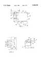
- FIG. 1is a side elevational view of the modular jack of the present invention
- FIG. 2is a fragmented top plan view of the modular jack shown in FIG. 1;
- FIG. 3is a fragmented front elevational view of the modular jack shown in FIG. 1;
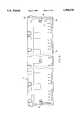
- FIG. 4is a fragmented bottom plan view of the modular jack shown in FIG. 1;
- FIG. 5is a detailed view from V--V in FIG. 1;
- FIG. 6is a detailed view of area VI in FIG. 1;
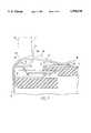
- FIG. 7is a schematic cross sectional view through VII--VII in FIG. 2 showing the operation of the shielding used in the modular jack of the present invention.
- the modular jack of the present inventionincludes an insulative housing shown generally at numeral 10.
- This housingincludes a lower horizontal longitudinal wall 12 and an upper horizontal longitudinal wall 14.
- the housingalso includes end lateral walls 16 and 18 as well as a plurality of intermediate lateral walls as at 20. Adjacent lateral walls as at 18 and 20 form plug receiving cavities as at 22. Each of these plug receiving cavities has a front open end 24 and a rear end 26. In each plug receiving cavity there is a medial wall 28 and steps as at 30 to form a key structure.
- the modular jackalso includes mounting pins as at 32 and conductive terminals as at 34 and 36.
- the modular jackalso includes a metallic shield shown generally at numeral 38.
- the metallic shieldincludes a first lateral member shown generally at 40 which has a horizontal wall 42 which is superimposed over upper horizontal wall 14 of the insulated housing.
- the first lateral portion 44also includes a rear vertical wall 43 superimposed over rear end 26 and a lateral vertical wall 44 which is superimposed over lateral wall 16 of the insulated housing and lateral vertical wall 46 which is superimposed over lateral wall 18 of the insulated housing.
- the first lateral member of the shieldhas a front peripheral edge 48, and rearwardly spaced from this edge there is a peripheral step 50. At spaced peripheral intervals there are additional deeper recesses, 52, 54, 56, 58, 60 and 62. Each of those recesses has an engagement aperture as at aperture 64 in recess 60.
- the first lateral member of the shieldalso includes grounding pins such as pin 66.
- the shieldalso includes a second vertical member which is shown generally at numeral 70. This second vertical member of the shield is engaged to the first lateral member of the shield by a system clips which is explained as follows.
- each of these recess engaging clipsincludes a rearward extension 74, a downward oblique section 76 and a pair of rearwardly extending legs 78 and 80 which have, respectively, rearward outwardly extending projections 82 and 84. These legs pass through recess apertures as at aperture 64 and the projections 82 and 84 grasp the edges of the apertures.
- each of these tabshas an upwardly and rearwardly curved section 90 and then a downwardly and rearwardly curved section 92 which abuts the first lateral section 40 of the shield.
- Each of these tabshas a rearwardly extending section 98 and an upwardly extending section 100.
- the three sets of tabsare used at spaced intervals along the peripheral edge 48 of the first member to effectively seal the modular jack from EMI. The use of multiple tabs also serves to effectively ground the shield and the modular jack.
- the front section 70 of the shieldis also engaged to the lower longitudinal wall 12 by means of lower horizontal clips as at clips 102 and 104.
- the modular jackis engaged with a panel 106 that the second horizontal clips as at 86 will be flexed by the lower edge 108 of the panel from the relaxed position at 86. It will also be seen that the generally vertical tabs as at 94 will engage the rear side 110 of the panel to firmly engage the panel and allow for effective shielding of the modular jack.
Landscapes
- Details Of Connecting Devices For Male And Female Coupling (AREA)
Abstract
Description
Claims (19)
Priority Applications (11)
| Application Number | Priority Date | Filing Date | Title |
|---|---|---|---|
| US08/690,548US5788538A (en) | 1996-07-31 | 1996-07-31 | Shield for modular jack |
| TW086211863UTW377892U (en) | 1996-07-31 | 1997-07-16 | Shield for modular jack |
| SG9702629ASG83668A1 (en) | 1996-07-31 | 1997-07-24 | Shield for modular jack |
| KR10-1997-0036049AKR100445282B1 (en) | 1996-07-31 | 1997-07-30 | Modular Jack Shield |
| DE69737664TDE69737664T2 (en) | 1996-07-31 | 1997-07-31 | Shielding for a modular jack connector |
| EP01113653AEP1133009B1 (en) | 1996-07-31 | 1997-07-31 | Shield for modular jack |
| EP97113257AEP0822623B1 (en) | 1996-07-31 | 1997-07-31 | Shield for modular jack |
| JP20649097AJP4060402B2 (en) | 1996-07-31 | 1997-07-31 | Modular jack assembly |
| DE69716834TDE69716834T2 (en) | 1996-07-31 | 1997-07-31 | Shielding for a modular jack connector |
| US08/936,105US5957726A (en) | 1996-07-31 | 1997-09-23 | Shield for modular jack |
| US09/382,098US6379185B2 (en) | 1996-07-31 | 1999-08-24 | Shield for modular jack |
Applications Claiming Priority (1)
| Application Number | Priority Date | Filing Date | Title |
|---|---|---|---|
| US08/690,548US5788538A (en) | 1996-07-31 | 1996-07-31 | Shield for modular jack |
Related Child Applications (1)
| Application Number | Title | Priority Date | Filing Date |
|---|---|---|---|
| US08/936,105DivisionUS5957726A (en) | 1996-07-31 | 1997-09-23 | Shield for modular jack |
Publications (1)
| Publication Number | Publication Date |
|---|---|
| US5788538Atrue US5788538A (en) | 1998-08-04 |
Family
ID=24772914
Family Applications (3)
| Application Number | Title | Priority Date | Filing Date |
|---|---|---|---|
| US08/690,548Expired - LifetimeUS5788538A (en) | 1996-07-31 | 1996-07-31 | Shield for modular jack |
| US08/936,105Expired - LifetimeUS5957726A (en) | 1996-07-31 | 1997-09-23 | Shield for modular jack |
| US09/382,098Expired - LifetimeUS6379185B2 (en) | 1996-07-31 | 1999-08-24 | Shield for modular jack |
Family Applications After (2)
| Application Number | Title | Priority Date | Filing Date |
|---|---|---|---|
| US08/936,105Expired - LifetimeUS5957726A (en) | 1996-07-31 | 1997-09-23 | Shield for modular jack |
| US09/382,098Expired - LifetimeUS6379185B2 (en) | 1996-07-31 | 1999-08-24 | Shield for modular jack |
Country Status (7)
| Country | Link |
|---|---|
| US (3) | US5788538A (en) |
| EP (2) | EP1133009B1 (en) |
| JP (1) | JP4060402B2 (en) |
| KR (1) | KR100445282B1 (en) |
| DE (2) | DE69737664T2 (en) |
| SG (1) | SG83668A1 (en) |
| TW (1) | TW377892U (en) |
Cited By (20)
| Publication number | Priority date | Publication date | Assignee | Title |
|---|---|---|---|---|
| US5961350A (en)* | 1997-07-31 | 1999-10-05 | The Whitaker Corporation | Modular side-by-side connectors |
| US5980320A (en)* | 1997-09-19 | 1999-11-09 | The Whitaker Corporation | Electrical connector having crimped ground shield |
| US6007382A (en)* | 1998-12-15 | 1999-12-28 | Hon Hai Precision Ind. Co., Ltd. | Electrical connector |
| US6146202A (en)* | 1998-08-12 | 2000-11-14 | Robinson Nugent, Inc. | Connector apparatus |
| USD434380S (en)* | 1999-10-15 | 2000-11-28 | Hirose Electric Co., Ltd. | Electrical connector |
| DE19938782A1 (en)* | 1999-08-16 | 2001-03-22 | Tyco Electronics Logistics Ag | Shielded electrical connector |
| US6231391B1 (en) | 1999-08-12 | 2001-05-15 | Robinson Nugent, Inc. | Connector apparatus |
| US6250964B1 (en)* | 1997-10-10 | 2001-06-26 | Stewart Connector Systems, Inc. | Shield for a jack |
| US6283791B1 (en)* | 1999-05-03 | 2001-09-04 | Accton Technology Corporation | EMI shielded connector of a hub |
| US6379185B2 (en)* | 1996-07-31 | 2002-04-30 | Fci Americas Technology, Inc. | Shield for modular jack |
| US6390851B1 (en)* | 1999-10-16 | 2002-05-21 | Berg Technology, Inc. | Electrical connector with internal shield |
| US6478624B2 (en) | 2000-06-29 | 2002-11-12 | Robinson Nugent, Inc. | High speed connector |
| US6641440B1 (en) | 2002-09-30 | 2003-11-04 | Hon Hai Precision Ind. Co., Ltd. | Electrical connector with power module |
| US6699071B1 (en) | 2002-10-23 | 2004-03-02 | Hon Hai Precision Ind. Co., Ltd. | Electrical connector with retention mechanism of outer shell |
| US6739915B1 (en) | 2002-11-05 | 2004-05-25 | Hon Hai Precision Ind. Co., Ltd. | Electrical connector with rear retention mechanism of outer shell |
| US6743047B2 (en) | 2002-10-23 | 2004-06-01 | Hon Hai Precision Ind. Co., Ltd. | Electrical connector with rear ground plate |
| USD496907S1 (en) | 2002-10-17 | 2004-10-05 | Hon Hai Precision Ind. Co., Ltd. | Small form-factor pluggable transceiver cage |
| US20100022131A1 (en)* | 2008-07-22 | 2010-01-28 | Amphenol Corporation | Registered jack with enhanced emi protection |
| US20110070774A1 (en)* | 2009-09-18 | 2011-03-24 | Hong Fu Jin Precision Industry (Shenzhen) Co., Ltd. | Computer enclosure |
| US9847607B2 (en) | 2014-04-23 | 2017-12-19 | Commscope Technologies Llc | Electrical connector with shield cap and shielded terminals |
Families Citing this family (18)
| Publication number | Priority date | Publication date | Assignee | Title |
|---|---|---|---|---|
| US6454603B2 (en)* | 1997-03-07 | 2002-09-24 | Berg Technology, Inc. | Shielded connector with integral latching and ground structure |
| JP3262758B2 (en)* | 1998-09-14 | 2002-03-04 | 日本圧着端子製造株式会社 | Flanged connector |
| TW433606U (en)* | 1999-06-01 | 2001-05-01 | Hon Hai Prec Ind Co Ltd | Cable connector |
| NL1012694C2 (en)* | 1999-07-23 | 2001-01-24 | Berg Electronics Mfg | Connector and plug or socket for use therein. |
| TW421307U (en)* | 1999-08-06 | 2001-02-01 | Hon Hai Prec Ind Co Ltd | Cable connector |
| EP1307952B1 (en) | 2000-08-10 | 2004-04-28 | Infineon Technologies AG | Shield, especially for optoelectronic transceivers |
| JP2002164126A (en)* | 2000-11-28 | 2002-06-07 | Jst Mfg Co Ltd | Modular jack |
| DE10102461C2 (en) | 2001-01-15 | 2002-12-05 | Infineon Technologies Ag | Shield plate for pluggable electrical components |
| CN2703341Y (en)* | 2004-01-08 | 2005-06-01 | 富士康(昆山)电脑接插件有限公司 | electrical connector |
| US6986681B2 (en)* | 2004-02-20 | 2006-01-17 | Advanced Connectek, Inc. | HDMI connector |
| US7232340B2 (en)* | 2004-02-20 | 2007-06-19 | Adc Incorporated | Methods and systems for minimizing alien crosstalk between connectors |
| US7261602B2 (en)* | 2005-01-04 | 2007-08-28 | Molex Incorporated | Retaining and grounding clip for adapter module |
| US7570487B2 (en)* | 2005-03-02 | 2009-08-04 | Adc Telecommunications, Inc. | Patch panel module and chassis |
| US7294024B2 (en)* | 2006-01-06 | 2007-11-13 | Adc Telecommunications, Inc. | Methods and systems for minimizing alien crosstalk between connectors |
| US7722402B2 (en)* | 2006-10-16 | 2010-05-25 | Tyco Electronics Corporation | Panel interface module which provides electrical connectivity between panel and shielded jacks |
| US8011958B1 (en)* | 2010-05-19 | 2011-09-06 | Amphenol East Asia Electronic Technology (Shenzhen) Ltd. | E-easy series connector assembly with shielding function |
| JP6747137B2 (en)* | 2016-07-25 | 2020-08-26 | コニカミノルタ株式会社 | Grounding structure for electronic devices and cable connectors connected to electronic devices |
| US10164378B2 (en) | 2017-03-30 | 2018-12-25 | Microsoft Technology Licensing, Llc | Grounding for high-speed connectors |
Citations (35)
| Publication number | Priority date | Publication date | Assignee | Title |
|---|---|---|---|---|
| US4386814A (en)* | 1981-08-17 | 1983-06-07 | Amp Incorporated | Kit for converting a panel opening to a shielded pin receptacle |
| US4655532A (en)* | 1986-02-06 | 1987-04-07 | Allied Corporation | Circumferential grounding and shielding ring for an electrical connector |
| US4820885A (en)* | 1987-09-25 | 1989-04-11 | Tom E Lindsay | Magnetic gasket for shielding against electromagnetic radiation |
| US4838811A (en)* | 1986-08-22 | 1989-06-13 | Hirose Electric Co., Ltd. | Modular connector with EMI countermeasure |
| US4878858A (en)* | 1988-12-13 | 1989-11-07 | Molex Incorporated | Low profile shielded jack |
| US4889958A (en)* | 1987-06-11 | 1989-12-26 | Shimizu Construction Co., Ltd. | Building with electromagnetic shield structure for individual floors |
| US4936795A (en)* | 1988-10-04 | 1990-06-26 | Hirose Electric Co., Ltd. | Electrical connector |
| US4938714A (en)* | 1988-10-04 | 1990-07-03 | Hirose Electric Co., Ltd. | Electrical connector |
| US4943244A (en)* | 1989-12-26 | 1990-07-24 | Molex Incorporated | Grounding electrical connector |
| US4966637A (en)* | 1988-01-13 | 1990-10-30 | Rollin, S.A. | Method for manufacturing an electromagnetic shielding gasket |
| US4980516A (en)* | 1988-10-26 | 1990-12-25 | Kitagawa Industries Co., Ltd. | Electromagnetic-shielding gasket |
| US4983127A (en)* | 1988-10-04 | 1991-01-08 | Hirose Electric Co., Ltd. | Electrical connector |
| US4993971A (en)* | 1988-03-07 | 1991-02-19 | Hirose Electric Co., Ltd. | EMI resistant electrical connector |
| US5022871A (en)* | 1989-11-29 | 1991-06-11 | Hosiden Corporation | Multipolar connector socket |
| US5072070A (en)* | 1989-12-01 | 1991-12-10 | Peter J. Balsells | Device for sealing electromagnetic waves |
| US5083945A (en)* | 1991-02-01 | 1992-01-28 | Molex Incorporated | Shielded electrical connector assembly |
| US5091606A (en)* | 1988-04-25 | 1992-02-25 | Peter J. Balsells | Gasket for sealing electromagnetic waves filled with a conductive material |
| US5147121A (en)* | 1989-11-13 | 1992-09-15 | Gichner Systems Group, Inc. | Gasket for providing EMI/RFI shielding |
| US5162980A (en)* | 1991-04-08 | 1992-11-10 | Digital Equipment Corporation | Shielded printed circuit board housing for high density storage |
| US5178562A (en)* | 1991-10-17 | 1993-01-12 | Epson Portland, Inc. | Contact member for miniature electrical circuit connector |
| US5195911A (en)* | 1992-01-22 | 1993-03-23 | Molex Incorporated | Shielded electrical connector with improved shield |
| US5204496A (en)* | 1992-04-01 | 1993-04-20 | Digital Equipment Corporation | EMI shielding gasket |
| US5207597A (en)* | 1991-06-21 | 1993-05-04 | Amp Incorporated | Shielded connector with dual cantilever panel grounding beam |
| US5228872A (en)* | 1992-05-05 | 1993-07-20 | Dan-Chief Enterprise Co., Ltd. | Shielded IDC type modular jack adapter |
| US5288248A (en)* | 1991-10-28 | 1994-02-22 | Foxconn International | Totally shielded DIN connector |
| US5348484A (en)* | 1993-06-17 | 1994-09-20 | General Datacomm, Inc. | Grounding spring clip for modular jacks |
| US5364574A (en)* | 1992-04-02 | 1994-11-15 | The United States Of America As Represented By The Secretary Of The Navy | Method of forming a corrosion-resistant EMI shielding gasket between graphite and metal components |
| EP0627791A1 (en)* | 1993-06-04 | 1994-12-07 | Framatome Connectors International | Connector assembly for printed circuit boards |
| US5378172A (en)* | 1994-03-10 | 1995-01-03 | Molex Incorporated | Low profile shielded jack |
| US5383098A (en)* | 1991-09-19 | 1995-01-17 | Motorola, Inc. | Shield assembly |
| US5397250A (en)* | 1993-04-06 | 1995-03-14 | Amphenol Corporation | Modular jack with filter |
| US5418023A (en)* | 1989-07-17 | 1995-05-23 | W. L. Gore & Associates, Inc. | Metallized microporous polytetrafluoroethylene electromagnetic energy shielding gasketing |
| US5496195A (en)* | 1995-03-13 | 1996-03-05 | The Whitaker Corporation | High performance shielded connector |
| US5511992A (en)* | 1992-10-29 | 1996-04-30 | Siemens Aktiengesellschaft | Device for molding a shielded cable plug |
| US5637015A (en)* | 1995-08-31 | 1997-06-10 | Hon Hai Precision Ind. Co., Ltd. | Shielded electrical connector |
Family Cites Families (2)
| Publication number | Priority date | Publication date | Assignee | Title |
|---|---|---|---|---|
| FR627791A (en) | 1927-01-19 | 1927-10-12 | Explosion turbine | |
| US5788538A (en)* | 1996-07-31 | 1998-08-04 | Berg Technology, Inc. | Shield for modular jack |
- 1996
- 1996-07-31USUS08/690,548patent/US5788538A/ennot_activeExpired - Lifetime
- 1997
- 1997-07-16TWTW086211863Upatent/TW377892U/enunknown
- 1997-07-24SGSG9702629Apatent/SG83668A1/enunknown
- 1997-07-30KRKR10-1997-0036049Apatent/KR100445282B1/ennot_activeExpired - Fee Related
- 1997-07-31DEDE69737664Tpatent/DE69737664T2/ennot_activeExpired - Lifetime
- 1997-07-31EPEP01113653Apatent/EP1133009B1/ennot_activeExpired - Lifetime
- 1997-07-31EPEP97113257Apatent/EP0822623B1/ennot_activeExpired - Lifetime
- 1997-07-31JPJP20649097Apatent/JP4060402B2/ennot_activeExpired - Fee Related
- 1997-07-31DEDE69716834Tpatent/DE69716834T2/ennot_activeExpired - Lifetime
- 1997-09-23USUS08/936,105patent/US5957726A/ennot_activeExpired - Lifetime
- 1999
- 1999-08-24USUS09/382,098patent/US6379185B2/ennot_activeExpired - Lifetime
Patent Citations (35)
| Publication number | Priority date | Publication date | Assignee | Title |
|---|---|---|---|---|
| US4386814A (en)* | 1981-08-17 | 1983-06-07 | Amp Incorporated | Kit for converting a panel opening to a shielded pin receptacle |
| US4655532A (en)* | 1986-02-06 | 1987-04-07 | Allied Corporation | Circumferential grounding and shielding ring for an electrical connector |
| US4838811A (en)* | 1986-08-22 | 1989-06-13 | Hirose Electric Co., Ltd. | Modular connector with EMI countermeasure |
| US4889958A (en)* | 1987-06-11 | 1989-12-26 | Shimizu Construction Co., Ltd. | Building with electromagnetic shield structure for individual floors |
| US4820885A (en)* | 1987-09-25 | 1989-04-11 | Tom E Lindsay | Magnetic gasket for shielding against electromagnetic radiation |
| US4966637A (en)* | 1988-01-13 | 1990-10-30 | Rollin, S.A. | Method for manufacturing an electromagnetic shielding gasket |
| US4993971A (en)* | 1988-03-07 | 1991-02-19 | Hirose Electric Co., Ltd. | EMI resistant electrical connector |
| US5091606A (en)* | 1988-04-25 | 1992-02-25 | Peter J. Balsells | Gasket for sealing electromagnetic waves filled with a conductive material |
| US4938714A (en)* | 1988-10-04 | 1990-07-03 | Hirose Electric Co., Ltd. | Electrical connector |
| US4936795A (en)* | 1988-10-04 | 1990-06-26 | Hirose Electric Co., Ltd. | Electrical connector |
| US4983127A (en)* | 1988-10-04 | 1991-01-08 | Hirose Electric Co., Ltd. | Electrical connector |
| US4980516A (en)* | 1988-10-26 | 1990-12-25 | Kitagawa Industries Co., Ltd. | Electromagnetic-shielding gasket |
| US4878858A (en)* | 1988-12-13 | 1989-11-07 | Molex Incorporated | Low profile shielded jack |
| US5418023A (en)* | 1989-07-17 | 1995-05-23 | W. L. Gore & Associates, Inc. | Metallized microporous polytetrafluoroethylene electromagnetic energy shielding gasketing |
| US5147121A (en)* | 1989-11-13 | 1992-09-15 | Gichner Systems Group, Inc. | Gasket for providing EMI/RFI shielding |
| US5022871A (en)* | 1989-11-29 | 1991-06-11 | Hosiden Corporation | Multipolar connector socket |
| US5072070A (en)* | 1989-12-01 | 1991-12-10 | Peter J. Balsells | Device for sealing electromagnetic waves |
| US4943244A (en)* | 1989-12-26 | 1990-07-24 | Molex Incorporated | Grounding electrical connector |
| US5083945A (en)* | 1991-02-01 | 1992-01-28 | Molex Incorporated | Shielded electrical connector assembly |
| US5162980A (en)* | 1991-04-08 | 1992-11-10 | Digital Equipment Corporation | Shielded printed circuit board housing for high density storage |
| US5207597A (en)* | 1991-06-21 | 1993-05-04 | Amp Incorporated | Shielded connector with dual cantilever panel grounding beam |
| US5383098A (en)* | 1991-09-19 | 1995-01-17 | Motorola, Inc. | Shield assembly |
| US5178562A (en)* | 1991-10-17 | 1993-01-12 | Epson Portland, Inc. | Contact member for miniature electrical circuit connector |
| US5288248A (en)* | 1991-10-28 | 1994-02-22 | Foxconn International | Totally shielded DIN connector |
| US5195911A (en)* | 1992-01-22 | 1993-03-23 | Molex Incorporated | Shielded electrical connector with improved shield |
| US5204496A (en)* | 1992-04-01 | 1993-04-20 | Digital Equipment Corporation | EMI shielding gasket |
| US5364574A (en)* | 1992-04-02 | 1994-11-15 | The United States Of America As Represented By The Secretary Of The Navy | Method of forming a corrosion-resistant EMI shielding gasket between graphite and metal components |
| US5228872A (en)* | 1992-05-05 | 1993-07-20 | Dan-Chief Enterprise Co., Ltd. | Shielded IDC type modular jack adapter |
| US5511992A (en)* | 1992-10-29 | 1996-04-30 | Siemens Aktiengesellschaft | Device for molding a shielded cable plug |
| US5397250A (en)* | 1993-04-06 | 1995-03-14 | Amphenol Corporation | Modular jack with filter |
| EP0627791A1 (en)* | 1993-06-04 | 1994-12-07 | Framatome Connectors International | Connector assembly for printed circuit boards |
| US5348484A (en)* | 1993-06-17 | 1994-09-20 | General Datacomm, Inc. | Grounding spring clip for modular jacks |
| US5378172A (en)* | 1994-03-10 | 1995-01-03 | Molex Incorporated | Low profile shielded jack |
| US5496195A (en)* | 1995-03-13 | 1996-03-05 | The Whitaker Corporation | High performance shielded connector |
| US5637015A (en)* | 1995-08-31 | 1997-06-10 | Hon Hai Precision Ind. Co., Ltd. | Shielded electrical connector |
Non-Patent Citations (1)
| Title |
|---|
| IBM Technical Disclosure Bulletin, vol. 30, No. 6, Nov. 1987.* |
Cited By (24)
| Publication number | Priority date | Publication date | Assignee | Title |
|---|---|---|---|---|
| US6379185B2 (en)* | 1996-07-31 | 2002-04-30 | Fci Americas Technology, Inc. | Shield for modular jack |
| US5961350A (en)* | 1997-07-31 | 1999-10-05 | The Whitaker Corporation | Modular side-by-side connectors |
| US5980320A (en)* | 1997-09-19 | 1999-11-09 | The Whitaker Corporation | Electrical connector having crimped ground shield |
| US6250964B1 (en)* | 1997-10-10 | 2001-06-26 | Stewart Connector Systems, Inc. | Shield for a jack |
| US6371813B2 (en) | 1998-08-12 | 2002-04-16 | Robinson Nugent, Inc. | Connector apparatus |
| US6146202A (en)* | 1998-08-12 | 2000-11-14 | Robinson Nugent, Inc. | Connector apparatus |
| US6007382A (en)* | 1998-12-15 | 1999-12-28 | Hon Hai Precision Ind. Co., Ltd. | Electrical connector |
| US6283791B1 (en)* | 1999-05-03 | 2001-09-04 | Accton Technology Corporation | EMI shielded connector of a hub |
| US6231391B1 (en) | 1999-08-12 | 2001-05-15 | Robinson Nugent, Inc. | Connector apparatus |
| DE19938782A1 (en)* | 1999-08-16 | 2001-03-22 | Tyco Electronics Logistics Ag | Shielded electrical connector |
| US6579124B1 (en) | 1999-08-16 | 2003-06-17 | Tyco Electronics Logistics Ag | Shielded electrical connector |
| USD434380S (en)* | 1999-10-15 | 2000-11-28 | Hirose Electric Co., Ltd. | Electrical connector |
| US6390851B1 (en)* | 1999-10-16 | 2002-05-21 | Berg Technology, Inc. | Electrical connector with internal shield |
| US6478624B2 (en) | 2000-06-29 | 2002-11-12 | Robinson Nugent, Inc. | High speed connector |
| US6641440B1 (en) | 2002-09-30 | 2003-11-04 | Hon Hai Precision Ind. Co., Ltd. | Electrical connector with power module |
| USD496907S1 (en) | 2002-10-17 | 2004-10-05 | Hon Hai Precision Ind. Co., Ltd. | Small form-factor pluggable transceiver cage |
| US6699071B1 (en) | 2002-10-23 | 2004-03-02 | Hon Hai Precision Ind. Co., Ltd. | Electrical connector with retention mechanism of outer shell |
| US6743047B2 (en) | 2002-10-23 | 2004-06-01 | Hon Hai Precision Ind. Co., Ltd. | Electrical connector with rear ground plate |
| US6739915B1 (en) | 2002-11-05 | 2004-05-25 | Hon Hai Precision Ind. Co., Ltd. | Electrical connector with rear retention mechanism of outer shell |
| US20100022131A1 (en)* | 2008-07-22 | 2010-01-28 | Amphenol Corporation | Registered jack with enhanced emi protection |
| US7704098B2 (en)* | 2008-07-22 | 2010-04-27 | Amphenol Corporation | Registered jack with enhanced EMI protection |
| US20110070774A1 (en)* | 2009-09-18 | 2011-03-24 | Hong Fu Jin Precision Industry (Shenzhen) Co., Ltd. | Computer enclosure |
| US9847607B2 (en) | 2014-04-23 | 2017-12-19 | Commscope Technologies Llc | Electrical connector with shield cap and shielded terminals |
| US10476212B2 (en) | 2014-04-23 | 2019-11-12 | Commscope Technologies Llc | Electrical connector with shield cap and shielded terminals |
Also Published As
| Publication number | Publication date |
|---|---|
| EP0822623A1 (en) | 1998-02-04 |
| US5957726A (en) | 1999-09-28 |
| JPH10233252A (en) | 1998-09-02 |
| US20010016454A1 (en) | 2001-08-23 |
| US6379185B2 (en) | 2002-04-30 |
| KR980012724A (en) | 1998-04-30 |
| EP1133009B1 (en) | 2007-04-25 |
| EP0822623B1 (en) | 2002-11-06 |
| KR100445282B1 (en) | 2004-10-14 |
| EP1133009A3 (en) | 2005-07-20 |
| DE69737664D1 (en) | 2007-06-06 |
| EP1133009A2 (en) | 2001-09-12 |
| TW377892U (en) | 1999-12-21 |
| DE69716834D1 (en) | 2002-12-12 |
| SG83668A1 (en) | 2001-10-16 |
| DE69737664T2 (en) | 2008-01-03 |
| DE69716834T2 (en) | 2003-09-18 |
| JP4060402B2 (en) | 2008-03-12 |
Similar Documents
| Publication | Publication Date | Title |
|---|---|---|
| US5788538A (en) | Shield for modular jack | |
| US5378172A (en) | Low profile shielded jack | |
| CA1273421A (en) | Shielded plug and jack connector | |
| US5702271A (en) | Ultra low profile board-mounted modular jack | |
| US5775946A (en) | Shielded multi-port connector and method of assembly | |
| US5865646A (en) | Connector shield with integral latching and ground structure | |
| EP0188876B1 (en) | Shielded electrical connector assembly | |
| US4878858A (en) | Low profile shielded jack | |
| US6250964B1 (en) | Shield for a jack | |
| US5059140A (en) | Shielded plug and jack connector | |
| US5934940A (en) | Shielded electrical connector | |
| EP1356551B1 (en) | High-density receptacle connector | |
| DE69702853T2 (en) | SHIELDED ELECTRICAL CONNECTOR | |
| US20080038963A1 (en) | Receptacle connector and apparatus having the same | |
| US20030129879A1 (en) | Shielded connector with integral latching and ground structure | |
| CN1211348A (en) | Shielded electrical connector | |
| US4889503A (en) | Shielded plug and jack connector | |
| US20010016453A1 (en) | Shielded connector with integral latching and ground structure | |
| WO1998013904A1 (en) | Hybrid grounded and stacked connector assembly with audio jacks | |
| US5667407A (en) | Shielded cable plug | |
| US4738638A (en) | Electrical connector with improved integral ground strap for shielded cable | |
| US6299480B1 (en) | Shielded modular connector | |
| US6065985A (en) | Modular jack with flexible shorting structure | |
| US5722859A (en) | Totally shielded electrical jack assembly for modular plugs | |
| EP1032078A1 (en) | Shielded electrical connector |
Legal Events
| Date | Code | Title | Description |
|---|---|---|---|
| AS | Assignment | Owner name:BERG TECHNOLOGY, INC., NEVADA Free format text:ASSIGNMENT OF ASSIGNORS INTEREST;ASSIGNORS:CURWEN, PETER D.;BELOPOLSKY, YAKOV;REEL/FRAME:008675/0004 Effective date:19960930 | |
| STCF | Information on status: patent grant | Free format text:PATENTED CASE | |
| FPAY | Fee payment | Year of fee payment:4 | |
| FPAY | Fee payment | Year of fee payment:8 | |
| AS | Assignment | Owner name:BANC OF AMERICA SECURITIES LIMITED, AS SECURITY AG Free format text:SECURITY AGREEMENT;ASSIGNOR:FCI AMERICAS TECHNOLOGY, INC.;REEL/FRAME:017400/0192 Effective date:20060331 | |
| AS | Assignment | Owner name:FCI AMERICAS TECHNOLOGY, INC., NEVADA Free format text:CHANGE OF NAME;ASSIGNOR:BERG TECHNOLOGY, INC.;REEL/FRAME:017422/0729 Effective date:20000808 | |
| FPAY | Fee payment | Year of fee payment:12 | |
| AS | Assignment | Owner name:FCI AMERICAS TECHNOLOGY LLC, NEVADA Free format text:CONVERSION TO LLC;ASSIGNOR:FCI AMERICAS TECHNOLOGY, INC.;REEL/FRAME:025957/0432 Effective date:20090930 | |
| AS | Assignment | Owner name:FCI AMERICAS TECHNOLOGY LLC (F/K/A FCI AMERICAS TE Free format text:RELEASE OF PATENT SECURITY INTEREST AT REEL/FRAME NO. 17400/0192;ASSIGNOR:BANC OF AMERICA SECURITIES LIMITED;REEL/FRAME:029377/0632 Effective date:20121026 |