US5788348A - Automated teller machine with enhanced service access - Google Patents
Automated teller machine with enhanced service accessDownload PDFInfo
- Publication number
- US5788348A US5788348AUS08/600,602US60060296AUS5788348AUS 5788348 AUS5788348 AUS 5788348AUS 60060296 AUS60060296 AUS 60060296AUS 5788348 AUS5788348 AUS 5788348A
- Authority
- US
- United States
- Prior art keywords
- fascia
- enclosure
- opening
- front opening
- interior area
- Prior art date
- Legal status (The legal status is an assumption and is not a legal conclusion. Google has not performed a legal analysis and makes no representation as to the accuracy of the status listed.)
- Expired - Lifetime
Links
Images


Classifications
- G—PHYSICS
- G07—CHECKING-DEVICES
- G07F—COIN-FREED OR LIKE APPARATUS
- G07F19/00—Complete banking systems; Coded card-freed arrangements adapted for dispensing or receiving monies or the like and posting such transactions to existing accounts, e.g. automatic teller machines
- G07F19/20—Automatic teller machines [ATMs]
- G07F19/201—Accessories of ATMs
- G—PHYSICS
- G07—CHECKING-DEVICES
- G07F—COIN-FREED OR LIKE APPARATUS
- G07F19/00—Complete banking systems; Coded card-freed arrangements adapted for dispensing or receiving monies or the like and posting such transactions to existing accounts, e.g. automatic teller machines
- G07F19/20—Automatic teller machines [ATMs]
- G07F19/205—Housing aspects of ATMs
- Y—GENERAL TAGGING OF NEW TECHNOLOGICAL DEVELOPMENTS; GENERAL TAGGING OF CROSS-SECTIONAL TECHNOLOGIES SPANNING OVER SEVERAL SECTIONS OF THE IPC; TECHNICAL SUBJECTS COVERED BY FORMER USPC CROSS-REFERENCE ART COLLECTIONS [XRACs] AND DIGESTS
- Y10—TECHNICAL SUBJECTS COVERED BY FORMER USPC
- Y10T—TECHNICAL SUBJECTS COVERED BY FORMER US CLASSIFICATION
- Y10T292/00—Closure fasteners
- Y10T292/08—Bolts
- Y10T292/1043—Swinging
- Y10T292/1044—Multiple head
- Y10T292/1045—Operating means
- Y10T292/1047—Closure
Definitions
- This inventionrelates to automated banking machines. Specifically, this invention relates to an automated teller machine enclosure which provides enhanced service access.
- ATMsAutomated teller machines
- Customers of financial institutionsmay perform banking transactions, make inquiries concerning the status of their accounts, pay bills and obtain other banking services using automated teller machines.
- a customeruses a magnetically coded card that is inserted into the machine.
- the customeralso inputs a personal identification number that allows the automated teller machine to verify the customer's identity.
- the customer's cardis returned along with one or more receipts which document the transactions conducted.
- automated teller machinesalso now have the capability of recording information in a customer's passbook. This is important to individuals who want to keep track of the growth of their savings while maintaining a hard copy record of the status of their account.
- automated teller machinesmay include a passbook printer and transport of the type shown in U.S. Pat. No. 5,507,481 which is owned by the assignee of the present invention.
- Automated teller machinesalso have the capability of providing complete customer statements which provide a record of all the transactions related to their account. Such statements may be provided within an automated teller machine using a statement printer mechanism of the type shown in U.S. Ser. No. 08/213,411 filed Mar. 15, 1994 and a statement presenter mechanism as shown in U.S. Pat. 5,435,542, both of which are owned by the assignee of the present invention.
- the problems of providing adequate service accessbecomes more complex.
- the devices for performing the various functionsmay be highly reliable, most require periodic servicing. Such servicing may include very infrequent repair or adjustment. In some cases the service required may include relatively frequent replacement of supplies such as paper or print ribbons.
- an automated banking machinehaving a generally rectangular enclosure which houses a plurality of banking machine components in an interior area.
- the enclosureincludes a front opening and a rear opening.
- the serviceable components of the machineare accessible through at least one of the front or rear openings.
- the machineincludes a service door which is movably mounted on the enclosure.
- the service dooris controlled by a lock and is operable to selectively close the rear opening when the machine is in operation.
- the service dooris opened when it is desired to gain access to the components which are accessible through the rear opening.
- the machinealso includes a fascia which is a part of the customer interface.
- the fasciais removably positioned in the front opening of the enclosure. When it is desired to service components which are accessible through the front opening or to service components that are mounted on the fascia, the fascia may be removed to open the front opening.
- the front fasciais secured in the front opening by a disengageable latch.
- the disengageable latchis accessible only from the interior area of the machine. This ensures that authorized personnel have gained access to the interior area of the machine by unlocking and opening the service door before the fascia may be removed.
- the components of the machine of the present inventionare supported on rollout trays.
- the rollout traysare configured so that the components thereon may be moved out of the enclosure through the front opening when the fascia is removed or the rear opening when the service door is opened.
- the rollout traysare preferably arranged in a side-by-side relation so that a service technician may work on components extended on one rollout tray while standing in an area that would be occupied by an adjacent rollout tray when that tray is extended from the machine. This arrangement enables a service technician to perform the servicing functions by sequentially extending and retracting the trays without ever having to leave the service footprint of the extended trays.
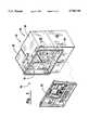
- FIG. 1is a front isometric exploded view of an automated banking machine enclosure of the present invention with the fascia of the enclosure in a removed condition.
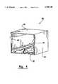
- FIG. 2is a rear plan view of the automated banking machine shown in FIG. 1 with a rear access door in an open condition.
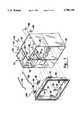
- FIG. 3is a rear isometric view of the automated banking machine shown in FIG. 2 with other rear access doors shown in an open condition and components of the machine extended therethrough on rollout trays.
- FIG. 4is a front isometric view of a universal enclosure component of the automated banking machine shown in FIG. 1.
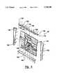
- FIG. 5is an isometric exploded view of a fascia of the automated banking machine shown in FIG. 1.
- FIG. 6is a rear isometric exploded view of a frame of the automated banking machine.
- FIG. 7is a front perspective view of the enclosure with the frame shown removed therefrom.
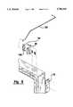
- FIG. 8is an isometric view of the frame shown in FIG. 7 and an enlarged view of a lock and release mechanism.
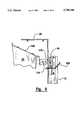
- FIG. 9is a side schematic view showing connection of a lock and a locking pin in connection with the fascia.
- FIG. 10is a rear plan view of the fascia.
- FIG. 11is a side schematic view of the lower portion of the fascia and frame moving towards an engaged position.
- FIG. 12is a side view similar to FIG. 11 showing the lower portion of the frame and fascia in engaged relation.
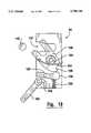
- FIG. 13is a cross sectional schematic view of the lock and locking pin.
- FIG. 14is a side cross sectional view of the lower portion of the fascia and the frame.
- Automated banking machine 10comprises an enclosure generally indicated 12.
- Enclosure 12bounds an interior area 14 of the automated banking machine which houses components of the machine.
- Enclosure 12has a front opening generally indicated 16 and a rear opening generally indicated 18.
- Enclosure 12includes a generally rectangular frame 20.
- Frame 20bounds the front opening.
- a fascia 22which serves as a customer interface for the automated banking machine, is removably positioned in frame 20 so as to close front opening 16.
- enclosure 12is comprised of a modular construction including a first enclosure portion 24 and a second enclosure portion 26.
- First enclosure portion 24is comprised of a generally rectangular upper housing 28.
- Upper housing 28is mounted above a secure chest 30, which in the preferred form of the invention is of a safe-like construction.
- Secure chest 30is closed by a safe door 32, the opening of which is controlled by a combination or other high security lock generally indicated 34 (see FIG. 2).
- Secure chest 30is used for holding items of value which may be stored within the ATM. This includes currency or deposits which may be made into the machine by customers.
- Secure chest 30includes openings 36 which enable the passage of such items of value to and from the interior of the secure chest.
- Upper housing 28is shown in greater detail in FIG. 4.
- Upper housing 28includes a top wall 38 and a pair of spaced side walls 40.
- Upper housing 28is of the type disclosed in U.S. Pat. No. 5,483,047 the disclosure of which is incorporated herein by reference.
- Upper housing 28further includes a pair of mounting areas 42 and 44.
- Mounting areas 42 and 44are adapted for connecting to a fixed type rectangular bracket so as to hold frame components thereto in a manner hereafter discussed.
- Mounting areas 42are also of the type that are adapted to accept a rotational bracket thereto which is used in other types of ATM fascias.
- Upper housing 28has a rollout tray 46 therein. As shown in FIG. 2, components of the automated banking machine are supportably mounted on rollout tray 46. In FIG. 2 a customer receipt printer and journal printer assembly generally indicated 48 is supportedly mounted on rollout tray 46. This component is only exemplary and in embodiments of the invention other types of components which perform other functions may be positioned on tray 46. This construction enables rollout tray 46 to be moved so as to extend outwardly through the rear opening 18 of the machine. This makes the component of the machine mounted on tray 46 much more accessible for servicing.
- upper housing 28includes a further rollout tray 50 which is positioned in side-by-side relation with rollout tray 46.
- Rollout tray 50supports a CRT generally indicated 52 and other components thereon.
- Rollout tray 50enables the CRT and other components supported thereon to be moved out the rear opening 18 of the machine supported on the rollout tray for servicing.
- rollout trays 46 and 50have been discussed with regard to moving out the rear opening 18 of the machine, in other embodiments they may be configured so as to be movable out the front opening 16 of the machine. Alternatively, in other embodiments one such rollout tray may be arranged to be movable out the front opening and the other movable out the rear opening. Further, in other embodiments each of the rollout trays may be movable either out the front opening or the rear opening by a service technician. The determination as to whether the rollout trays are movable out the front or the rear openings will depend on the arrangement of components inside the automated banking machine as well as the space constraints in the area where the machine is located.
- space constraintsmay dictate that all servicing be done from the front in which case the rollout trays would be arranged to extend from the front of the machine and the safe door of the secure chest 30 would be relocated so as to be either in the front or on a side of the machine.
- a fundamental advantage of the service configuration shown in FIG. 2is that the amount of floor space required for servicing the machine is minimized. This is achieved by enabling the technician to extend one of the rollout trays to service components thereon while leaving the other rollout tray within the interior area of the machine. This enables the service technician to stand in the floor space that would be occupied by the components on the other rollout tray when extended. When the service technician has completed work on the components on the extended tray, he or she could then return those components by moving them back into the interior area by retracting the rollout tray, move to the floor space previously occupied by the extended tray and extend the adjacent rollout tray to service the components thereon.
- Upper housing 18has a service door 54 attached thereto in hinged relation.
- Service door 54is selectively movable between an open position shown in FIG. 2 wherein access to the components of the machine is provided through rear opening 18.
- Service door 54is also selectively movable to a closed position shown in FIG. 3 wherein the rear opening of upper housing 28 is closed.
- Service door 54has a lock 56 in connection therewith.
- lock 56is a key-type lock which limits access to the interior area 14 of the machine to only authorized personnel.
- Second enclosure portion 26includes an upper service door 58 and a lower service door 60.
- Upper and lower service doors 58 and 60are each controlled by key locks or other conventional type locks.
- upper service door 58is mounted in hinged relation on second enclosure portion 26 and is selectively movable to an open condition.
- a rollout tray 62is movable out of the rear opening 18 of second enclosure portion 26.
- Rollout tray 62has components of the automated banking machine supported thereon.
- the components supported on tray 62are a passbook transport and printer mechanism generally indicated 64.
- Lower service door 60is also movable to an open condition as shown in FIG. 3.
- a further rollout tray 66is movable to extend from the enclosure 12 to facilitate servicing of the components thereon.
- rollout tray 66supports a check accepter validater generally indicated 68.
- rollout trays 62 and 66are shown as extending from the rear opening 18 of the second enclosure portion, it should be understood that in other embodiments of the invention such rollout trays may be configured with components so as to be extendable from a front opening or from both a front opening and a rear opening. It should further be mentioned that each of rollout trays 62 and 66 are independently movable. This enables the components on one tray to be extended for servicing while the other components remain retracted and out of the way of the service technician. After servicing the components on the extended tray such tray may be returned to the interior area of the machine and the tray above or below the prior tray extended to service the components thereon. This arrangement also greatly improves service access and reduces the floor space required for servicing in the same manner as with the trays arranged in a horizontal side-by-side arrangement.
- first enclosure portion 24 and second enclosure portion 26are held in adjacent relation by fasteners.
- a wiring enclosure 69extends between the enclosure portions.
- Second enclosure portion 26further includes a frame mounting area 70.
- Frame mounting area 70is disposed in opposed relation with mounting area 42 of the first enclosure portion.
- frame 20includes a first mounting bracket 72 and a second mounting bracket 74.
- First mounting bracketis engaged to mounting area 42 by conventional fasteners.
- Mounting bracket 74is engaged to frame mounting area 70 by fasteners.
- Frame 20further includes a central mounting bracket 76. Central mounting bracket 76 is engaged with mounting area 44 to further hold the frame in engaged relation with the rest of the enclosure.
- Frame 20further includes horizontally extending tabs 78, 80 and 82 through which fasteners extend to engage the frame with the rest of the enclosure.
- frame 20further includes a trim ring 84.
- Trim ring 84is attached to the rest of the frame by channels 86 which extend outward on all sides of the frame.
- a gasket 88comprised of resilient material extends between the channels and the trim ring.
- Frame 16includes a lower inside surface 90.
- Three latching brackets 92are mounted to the frame on lower inside surface 90.
- Latching brackets 92are part of a disengageable latch for holding the fascia in engagement with the frame as later discussed in detail.
- a first lock 94is connected to a first lock bracket 96 by fasteners.
- First lock bracket 96is in turn attached to first mounting bracket 72.
- a second lock 98is similarly attached to a second lock bracket 100 by fasteners.
- Second lock bracket 100is fastened to second mounting bracket 74.
- Lock 94is connected to a release arm 102.
- Release arm 102extends through openings in arm mounting brackets 104 and 106 which attach to the top wall 38 of first enclosure portion 24.
- Release arm 102is movable in arm mounting brackets 104 and 106 so as to move a release lever 108 on lock 94 (see FIG. 8).
- Lock 98has a second release arm 110 similar to release arm 102.
- Release arm 110is movably supported in arm mounting brackets 112 and 114 which are mounted to the top wall of second enclosure portion 26.
- Lock 98includes a release lever similar to that of lock 94 which engages release arm 110.
- the release arms 102 and 118are connected to locks 94 and 98 respectively, and serve as release members which when actuated unlock the respective lock.
- the release armsare positioned in the interior area 14 of the ATM enclosure.
- first and second locks 94 and 98are similar in construction, only lock 94 will be described in detail.
- a schematic cross sectional view of lock 94is shown in FIG. 13.
- the lockincludes a slot generally indicated 116. Slot 116 is sized for releasibly accepting a locking pin which as later discussed, is in fixed connection with the fascia 22.
- the lockfurther includes a latching pawl 120. Latching pawl 120 is rotatably mounted about a pivot 124 and is biased in a counterclockwise direction as shown by a spring 122.
- Latching pawl 120includes a catch 126 thereon.
- Catch 126is engageable with a lever 128 which is biased to engage the step by a spring 130.
- Lever 128is rotatable about a pivot 132.
- Release lever 108is biased in the clockwise direction as shown in FIG. 13 by a spring not shown.
- Release lever 108includes a cam surface 134 thereon.
- FIG. 13is only exemplary. Other types of locks may be used in embodiments of the invention as part of the disengageable latch for holding the fascia in engagement with the enclosure. Further, in alternative embodiments the positions of the locking pins and locks may be reversed wherein the locks are supported on the fascia and the locking pins are supported on the frame or the enclosure.
- Fascia 16includes a customer interface panel 136.
- Customer interface panel 136has supported thereon customer input devices such as a keyboard 138 and function buttons 140.
- Function buttons 140are positioned adjacent to a screen opening 142 through which the screen of the CRT may be viewed by a customer when the fascia and CRT are in the operative positions.
- the customer interface panel 136further includes a number of openings for passing items therethrough to other components of the machine. The openings are used to pass items such as credit and debit cards, deposits, cash, checks and passbooks.
- Each of the various openings in the customer interface panel 136generally has a sensor or other indicators adjacent thereto for sensing the passage of items through the opening. As later discussed, these sensors are mounted in supported connection with the fascia as are the input devices.
- a pair of side panels 144 and 146are attached to the sides of the customer interface panel 136.
- Side panel 144has an outward extending lip 148 extending along the front thereof.
- side panel 146has an outward extending lip 150 extending outwardly therefrom.
- a lower panel 152is attached by fasteners to the bottom of the customer interface panel 136.
- Lower panel 152extends between the side panels 144 and 146 and is attached thereto by fasteners as shown.
- Lower panel 142further includes an outward extending lip 154 thereon.
- a top panel 156is attached to the top of the customer interface panel 136 by fasteners. Top panel 156 is also attached to the tops of the side panels 144 and 146. Top panel 156 further includes an outward extending lip 158 at the front thereof. Panel 156 further includes spaced recesses generally indicated 160 that extend in the exterior surface thereof. Recesses 160 do not extend through the top panel 156 but rather serve as fingerholds to facilitate manually engaging the panel. The lips of the four panels surrounding panel 136 form a generally continuous outward extending lip which extends about a periphery of the fascia.
- Top panel 156further includes a pair of spaced ears 162 at the sides thereof. Ears 162 extend inwardly in the interior area of the enclosure. A locking pin 118 is mounted on each of ears 162.
- the locking pins 118along with locks 94 and 96 previously discussed, form part of a disengageable latch for the fascia 22.
- the ears 162 on top panel 156extend inboard of the locks.
- the pins attached to the earsare aligned with the slots of the locks such as slot 118 of lock 94 shown.
- locking pins 118extend sufficiently into the slots so as to rotate the latching pawls. This holds both locking pins 118 in locked relation in the locks.
- the latching pinsremain engaged with the locks until each of the release levers 108 and 110 are actuated so as to enable the top of the fascia to be moved to an outward position as shown in FIG. 9.
- the preferred embodiment of the disengageable latch of the present inventionfurther includes a first projecting bracket 164 which is attached to a lower portion of the back of customer interface panel 136 as shown in FIG. 10.
- a second projecting bracket 166is attached to the back of the customer interface panel in a similar manner.
- first and second projecting brackets 164 and 166are operative to hold fascia 22 positioned in the frame by engagement with latching brackets 92.
- Each of the latching brackets 92include a recess 168.
- a ramp portion 170extends outwardly of recess 168 towards the front of the frame 20.
- first projecting bracket 164 and second projecting bracket 166are movable into engagement with the recesses 168 of latching brackets 92. This is preferably accomplished by engaging the lip 154 of the lower panel 152 with the outer surface of the frame, channel and trim ring assembly (see FIG. 14). The fascia is then rotated into position such that the projections engage the recesses 168 in the latching brackets. As the projections engage the recesses the locking pins 118 rotate into engagement with the locks 94 and 98 as shown in FIG. 9.
- the ramps 170 being outwardly positioned of the recessesfacilitate engagement of the projections in the recesses by avoiding snagging and by enabling the projecting brackets 164 and 166 to be slid up the ramps 170 of the latching brackets 92.
- the fasciaWith the projecting brackets 164 and 166 engaged in the recesses 168 of the latching brackets and the locking pins 118 engaged in the locks 94 and 98, the fascia is held securely in position extending within frame 20. The fascia is held in this position until it is desired to remove it.
- the service doors 54 and 58must be unlocked and moved to an open condition sufficient to enable access to release arms 102 and 110. Moving the release arms rearwardly unlocks the locks and rotates the latching pawls thereof so as to push the locking pins 118 outward.
- the locking pinsare biased outwardly by the springs that are in operative connection with the latching pawls.
- a service technicianmay engage his or her fingers in the recesses 160 of the top panel 156 so as to move the top of the panel outwardly.
- the technicianrotates the fascia to disengage projecting brackets 164 and 166 from the recesses in latching brackets 92. This enables the fascia to be moved outwardly from the front opening 16.
- the projections and the projecting bracketsare fixed relative to the fascia and the interengaging recesses which accept the projections are fixed relative to the enclosure, in other embodiments other arrangements may be used including the reverse of the arrangement of the preferred embodiment.
- the input devices, sensors and other electrical items that are mounted on the interior of the customer interface panelare connected through a wiring harness with releasible connectors 172, 174 and 176 thereon.
- the releasible connectorsare enabled to be disengaged from mating connectors inside the machine so as to enable the . fascia to be removed from the machine entirely. This fully opens the front opening 16 of both enclosure portions 24 and 26 so as to provide service access and enable the rollout trays and serviceable components thereon to be extended out the front opening.
- a further advantage associated with having a fully removable fasciais the ability to easily test and replace the input devices, sensors and other electrical devices mounted thereon. This is achieved because with the fascia removed ready access is available to the components and fasteners on the fascia panel.
- the input devices, sensors and other electrical components on the fascia panelmay be readily tested. This is done either through testing or by connecting the releasible connectors 172, 174 or 176 to the mating connectors in the interior area 14 with jumper cables. This enables the service technician to operate the input devices, sensors and other electrical devices and observe the operation of the machine components in the interior area of the machine through the front opening or to test the functioning of such components with test equipment. This facilitates trouble shooting of the machine.
- the second enclosure portion 26has been added to the first enclosure portion, other embodiments of the invention may be comprised of a frame corresponding in size to only the first enclosure portion. Such an enclosure would still provide the benefits of the present invention including a removable front fascia which provides access to the interior area of the enclosure through both a front opening or a rear opening.
- Alternative embodiments of the inventionmay also include a second enclosure portion identical to the first enclosure portion which includes a second secure chest.
- Such an enclosurewould provide a double wide machine and additional space for holding valuable items such as cash or deposits.
- Such a machinemay be readily accommodated by adjusting the size of the frame and fascia portions to correspond to the width of the enclosure.
- machine enclosures corresponding to various combinations of first and second enclosure portionsmay be made. This enables structuring an enclosure so as to meet the needs and requirements of the particular components that are to be housed in the machine and which require periodic servicing.
- the new automated teller machine with improved service access of the present inventionachieves the above-stated objectives, eliminates difficulties encountered in the use of prior devices and systems, solves problems and attains the desirable results described herein.
Landscapes
- Business, Economics & Management (AREA)
- Accounting & Taxation (AREA)
- Finance (AREA)
- Physics & Mathematics (AREA)
- General Physics & Mathematics (AREA)
- Casings For Electric Apparatus (AREA)
- Control Of Vending Devices And Auxiliary Devices For Vending Devices (AREA)
- Replacement Of Web Rolls (AREA)
Abstract
Description
Claims (49)
Priority Applications (10)
| Application Number | Priority Date | Filing Date | Title |
|---|---|---|---|
| US08/600,602US5788348A (en) | 1994-03-15 | 1996-02-12 | Automated teller machine with enhanced service access |
| DE69739116TDE69739116D1 (en) | 1996-02-12 | 1997-01-14 | GELDAUSGABEAUTOMAT WITH IMPROVED MAINTENANCE ACCESS |
| CA002230283ACA2230283C (en) | 1996-02-12 | 1997-01-14 | Automated teller machine with enhanced service access |
| PCT/US1997/000421WO1997029444A1 (en) | 1996-02-12 | 1997-01-14 | Automated teller machine with enhanced service access |
| ES97901983TES2317649T3 (en) | 1996-02-12 | 1997-01-14 | AUTOMATIC CASH MACHINE WITH IMPROVED ACCESS FOR MAINTENANCE. |
| CN97191439ACN1111816C (en) | 1996-02-12 | 1997-01-14 | Automatic teller machine with improved maintenance access and method thereof |
| EP97901983AEP0892961B1 (en) | 1996-02-12 | 1997-01-14 | Automated teller machine with enhanced service access |
| BR9706568ABR9706568A (en) | 1996-02-12 | 1997-01-14 | ATM machine with enhanced access to services |
| RU98117136/09ARU2154304C2 (en) | 1996-02-12 | 1997-01-14 | Augmented-access autoteller machine |
| MX9801834AMX9801834A (en) | 1996-02-12 | 1998-03-06 | Automated teller machine with enhanced service access. |
Applications Claiming Priority (3)
| Application Number | Priority Date | Filing Date | Title |
|---|---|---|---|
| US08/213,404US5483047A (en) | 1994-03-15 | 1994-03-15 | Automated teller machine |
| US08/529,960US5642922A (en) | 1994-03-15 | 1995-09-19 | Automated teller machine monitor mount |
| US08/600,602US5788348A (en) | 1994-03-15 | 1996-02-12 | Automated teller machine with enhanced service access |
Related Parent Applications (1)
| Application Number | Title | Priority Date | Filing Date |
|---|---|---|---|
| US08/529,960Continuation-In-PartUS5642922A (en) | 1994-03-15 | 1995-09-19 | Automated teller machine monitor mount |
Publications (1)
| Publication Number | Publication Date |
|---|---|
| US5788348Atrue US5788348A (en) | 1998-08-04 |
Family
ID=24404258
Family Applications (1)
| Application Number | Title | Priority Date | Filing Date |
|---|---|---|---|
| US08/600,602Expired - LifetimeUS5788348A (en) | 1994-03-15 | 1996-02-12 | Automated teller machine with enhanced service access |
Country Status (10)
| Country | Link |
|---|---|
| US (1) | US5788348A (en) |
| EP (1) | EP0892961B1 (en) |
| CN (1) | CN1111816C (en) |
| BR (1) | BR9706568A (en) |
| CA (1) | CA2230283C (en) |
| DE (1) | DE69739116D1 (en) |
| ES (1) | ES2317649T3 (en) |
| MX (1) | MX9801834A (en) |
| RU (1) | RU2154304C2 (en) |
| WO (1) | WO1997029444A1 (en) |
Cited By (28)
| Publication number | Priority date | Publication date | Assignee | Title |
|---|---|---|---|---|
| US5984177A (en)* | 1996-08-16 | 1999-11-16 | Transaction Technology, Inc. | Multiple configuration automatic teller machine |
| US6024027A (en)* | 1997-11-28 | 2000-02-15 | Diebold Incorporated | Through the wall mounting for atm |
| US6036290A (en)* | 1998-03-13 | 2000-03-14 | Hoffman Enclosures, Inc. | Seismic subframe for electrical enclosure |
| WO2000031694A3 (en)* | 1998-11-25 | 2000-11-16 | Diebold Inc | Automated banking machine enclosure |
| EP0981117A3 (en)* | 1998-08-20 | 2001-10-10 | Ncr International Inc. | Self-service terminal |
| US6328206B1 (en)* | 1997-11-28 | 2001-12-11 | Diebold, Incorporated | Adjustable display mounting mechanism for automated banking machine |
| JP2002056430A (en)* | 2000-08-11 | 2002-02-22 | Oki Joho Systems:Kk | Automatic transaction device |
| US20020146271A1 (en)* | 1999-10-16 | 2002-10-10 | Sierra Design Group | Vertically mounted modular printer system |
| US20020194793A1 (en)* | 2001-01-26 | 2002-12-26 | Julian Bowron | Modular kiosk |
| US6502746B1 (en)* | 1998-09-02 | 2003-01-07 | Citicorp Development Center, Inc. | Device, method, and system for extracting deposited items from an ATM/CAT safe |
| US20030209598A1 (en)* | 2002-05-13 | 2003-11-13 | Dollhopf Kenneth J. | Car wash entry station with security vault |
| US6814518B2 (en)* | 1999-10-16 | 2004-11-09 | Sierra Design Group | Secure printer system for gaming devices |
| US20050057126A1 (en)* | 2003-09-16 | 2005-03-17 | Prometrix Corporation | Modular security enclosure for gaming machine |
| US20050151451A1 (en)* | 2004-01-09 | 2005-07-14 | Yu Chen | Attachable frame for flat display panels |
| US20060012184A1 (en)* | 2004-07-19 | 2006-01-19 | Kenneth Ottesen | Gaming machine lid/door latch |
| US20060032913A1 (en)* | 2003-02-10 | 2006-02-16 | Akira Nomiyama | Banknote receipt and payout apparatus |
| US7001001B1 (en)* | 2002-09-03 | 2006-02-21 | A & A Sheet Metal Products, Inc. | Cabinet |
| US20060181000A1 (en)* | 2002-10-30 | 2006-08-17 | Glory Ltd. | Bank note processing machine with temporary storage portion |
| US20070108267A1 (en)* | 2005-11-11 | 2007-05-17 | Manfred Jonsson | Cash Deposit Apparatus and Associated Methods and Devices |
| US7513401B1 (en) | 2000-06-19 | 2009-04-07 | Bally Gaming, Inc. | Printer tear bar and presenter system |
| US7611045B1 (en)* | 2005-06-03 | 2009-11-03 | Diebold Self-Service Systems Division Of Diebold, Incorporated | Enclosure for automated banking machine |
| US20090283488A1 (en)* | 2008-05-19 | 2009-11-19 | Chatsworth Products, Inc. | Seismically hardened two-post electronic equipment rack |
| US20100200447A1 (en)* | 2005-12-19 | 2010-08-12 | Mei, Inc. | Dispensing Value Sheet Store |
| US8127985B1 (en)* | 2008-01-02 | 2012-03-06 | Diebold Self-Service Systems Division Of Diebold, Incorporated | Automated banking machine operated responsive to data bearing records |
| US20120091869A1 (en)* | 2009-04-30 | 2012-04-19 | Vanexport | Retaining an interface on an automated product dispsenser |
| EP3323081A4 (en)* | 2015-07-14 | 2019-08-21 | Zivelo Inc. | Interactive kiosk systems and methods for their manufacture |
| US11065777B2 (en)* | 2018-10-17 | 2021-07-20 | Alexander Homsky | Slicing machine |
| US20240052686A1 (en)* | 2020-12-18 | 2024-02-15 | Jason Augustin KORDA | Retractable housing assembly |
Families Citing this family (8)
| Publication number | Priority date | Publication date | Assignee | Title |
|---|---|---|---|---|
| GB9811069D0 (en) | 1998-05-23 | 1998-07-22 | Ncr Int Inc | Modular self service terminal |
| FR2815752A1 (en)* | 2000-10-24 | 2002-04-26 | Sodifrance C2S | Electronic payment terminal for payment by card |
| US6766943B2 (en)* | 2002-11-25 | 2004-07-27 | Diebold Self-Service Systems, Division Of Diebold, Incorporated | Automated banking machine housing with improved service access |
| CA2733303C (en)* | 2003-03-10 | 2014-12-23 | Diebold, Incorporated | Cash dispensing automated banking machine with service monitor |
| DE202009009550U1 (en)* | 2009-07-10 | 2010-11-18 | Crown Technologies Gmbh | Device for managing, recording and / or delivering valuables |
| CN103150819B (en)* | 2012-08-16 | 2015-12-16 | 苏州艾隆科技股份有限公司 | Automatic medicine selling machine |
| WO2018076012A1 (en)* | 2016-10-23 | 2018-04-26 | Diebold Nixdorf, Incorporated | Automated transaction machine |
| EP3990740A4 (en)* | 2019-06-25 | 2023-08-09 | Diebold Nixdorf Incorporated | AUTOMATED TRANSACTION MACHINE HAVING A MONOBLOCK STRUCTURE |
Citations (15)
| Publication number | Priority date | Publication date | Assignee | Title |
|---|---|---|---|---|
| US3228553A (en)* | 1961-11-24 | 1966-01-11 | Rock Ola Mfg Corp | Packet dispensing mechanism |
| US4154437A (en)* | 1977-07-15 | 1979-05-15 | Diebold, Incorporated | Multiple bill detector for currency dispensers |
| JPS54148599A (en)* | 1978-05-15 | 1979-11-20 | Toshiba Corp | Automatic paying apparatus of cash |
| US4370006A (en)* | 1980-10-03 | 1983-01-25 | Diebold Incorporated | Banking media security mechanism for automatic banking machines |
| US4595828A (en)* | 1982-03-17 | 1986-06-17 | Leif Lundblad | Wall-mounted apparatus for dispensing and/or depositing valuable papers |
| US4754126A (en)* | 1987-04-01 | 1988-06-28 | Ncr Corporation | Night depository method and apparatus |
| US4775783A (en)* | 1985-08-02 | 1988-10-04 | Hitachi, Ltd. | Transaction system |
| US4917420A (en)* | 1989-02-21 | 1990-04-17 | General Motors Corporation | Low effort cable release hood latch assembly |
| GB2225891A (en)* | 1988-10-31 | 1990-06-13 | Toshiba Kk | Automatic teller machine |
| US5017026A (en)* | 1989-05-19 | 1991-05-21 | Kabushiki Kaisha Toshiba | Apparatus for automatically exchanging a passbook |
| US5112119A (en)* | 1989-10-27 | 1992-05-12 | International Business Machines Corp. | Support structure for devices in a computer apparatus |
| US5127686A (en)* | 1991-02-14 | 1992-07-07 | Tri-Mark Corporation | Door closure assembly |
| JPH05143822A (en)* | 1991-11-25 | 1993-06-11 | Oki Electric Ind Co Ltd | Automatic paper money payment device |
| US5568362A (en)* | 1992-09-25 | 1996-10-22 | Atlas Copco Tools Ab | Cabinet for housing electronic equipment connectable to machines or power tools for performing operations |
| US5570915A (en)* | 1993-11-30 | 1996-11-05 | Adams Rite Sabre International | Flush-mounted door latch |
Family Cites Families (5)
| Publication number | Priority date | Publication date | Assignee | Title |
|---|---|---|---|---|
| BE755530A (en)* | 1969-09-09 | 1971-02-01 | Speytec Ltd | DISTRIBUTION SYSTEM AND SECURITY CARD TO BE USED WITH THIS |
| US5422467A (en)* | 1993-01-15 | 1995-06-06 | Interbold | Article depositing apparatus |
| US5435542A (en)* | 1994-03-15 | 1995-07-25 | Interbold | Statement presenter mechanism for automated teller machine |
| US5483047A (en) | 1994-03-15 | 1996-01-09 | Inter Bold | Automated teller machine |
| US5507481A (en) | 1994-06-10 | 1996-04-16 | Interbold | Automated teller machine passbook transport mechanism |
- 1996
- 1996-02-12USUS08/600,602patent/US5788348A/ennot_activeExpired - Lifetime
- 1997
- 1997-01-14RURU98117136/09Apatent/RU2154304C2/ennot_activeIP Right Cessation
- 1997-01-14WOPCT/US1997/000421patent/WO1997029444A1/enactiveApplication Filing
- 1997-01-14CACA002230283Apatent/CA2230283C/ennot_activeExpired - Lifetime
- 1997-01-14DEDE69739116Tpatent/DE69739116D1/ennot_activeExpired - Lifetime
- 1997-01-14CNCN97191439Apatent/CN1111816C/ennot_activeExpired - Lifetime
- 1997-01-14EPEP97901983Apatent/EP0892961B1/ennot_activeExpired - Lifetime
- 1997-01-14BRBR9706568Apatent/BR9706568A/ennot_activeIP Right Cessation
- 1997-01-14ESES97901983Tpatent/ES2317649T3/ennot_activeExpired - Lifetime
- 1998
- 1998-03-06MXMX9801834Apatent/MX9801834A/enunknown
Patent Citations (15)
| Publication number | Priority date | Publication date | Assignee | Title |
|---|---|---|---|---|
| US3228553A (en)* | 1961-11-24 | 1966-01-11 | Rock Ola Mfg Corp | Packet dispensing mechanism |
| US4154437A (en)* | 1977-07-15 | 1979-05-15 | Diebold, Incorporated | Multiple bill detector for currency dispensers |
| JPS54148599A (en)* | 1978-05-15 | 1979-11-20 | Toshiba Corp | Automatic paying apparatus of cash |
| US4370006A (en)* | 1980-10-03 | 1983-01-25 | Diebold Incorporated | Banking media security mechanism for automatic banking machines |
| US4595828A (en)* | 1982-03-17 | 1986-06-17 | Leif Lundblad | Wall-mounted apparatus for dispensing and/or depositing valuable papers |
| US4775783A (en)* | 1985-08-02 | 1988-10-04 | Hitachi, Ltd. | Transaction system |
| US4754126A (en)* | 1987-04-01 | 1988-06-28 | Ncr Corporation | Night depository method and apparatus |
| GB2225891A (en)* | 1988-10-31 | 1990-06-13 | Toshiba Kk | Automatic teller machine |
| US4917420A (en)* | 1989-02-21 | 1990-04-17 | General Motors Corporation | Low effort cable release hood latch assembly |
| US5017026A (en)* | 1989-05-19 | 1991-05-21 | Kabushiki Kaisha Toshiba | Apparatus for automatically exchanging a passbook |
| US5112119A (en)* | 1989-10-27 | 1992-05-12 | International Business Machines Corp. | Support structure for devices in a computer apparatus |
| US5127686A (en)* | 1991-02-14 | 1992-07-07 | Tri-Mark Corporation | Door closure assembly |
| JPH05143822A (en)* | 1991-11-25 | 1993-06-11 | Oki Electric Ind Co Ltd | Automatic paper money payment device |
| US5568362A (en)* | 1992-09-25 | 1996-10-22 | Atlas Copco Tools Ab | Cabinet for housing electronic equipment connectable to machines or power tools for performing operations |
| US5570915A (en)* | 1993-11-30 | 1996-11-05 | Adams Rite Sabre International | Flush-mounted door latch |
Cited By (45)
| Publication number | Priority date | Publication date | Assignee | Title |
|---|---|---|---|---|
| US5984177A (en)* | 1996-08-16 | 1999-11-16 | Transaction Technology, Inc. | Multiple configuration automatic teller machine |
| US6024027A (en)* | 1997-11-28 | 2000-02-15 | Diebold Incorporated | Through the wall mounting for atm |
| US6328206B1 (en)* | 1997-11-28 | 2001-12-11 | Diebold, Incorporated | Adjustable display mounting mechanism for automated banking machine |
| US6036290A (en)* | 1998-03-13 | 2000-03-14 | Hoffman Enclosures, Inc. | Seismic subframe for electrical enclosure |
| EP0981117A3 (en)* | 1998-08-20 | 2001-10-10 | Ncr International Inc. | Self-service terminal |
| US6502746B1 (en)* | 1998-09-02 | 2003-01-07 | Citicorp Development Center, Inc. | Device, method, and system for extracting deposited items from an ATM/CAT safe |
| US6527172B1 (en) | 1998-11-25 | 2003-03-04 | Diebold, Incorporated | Automated banking machine enclosure |
| WO2000031694A3 (en)* | 1998-11-25 | 2000-11-16 | Diebold Inc | Automated banking machine enclosure |
| RU2219817C2 (en)* | 1998-11-25 | 2003-12-27 | Дайболд, Инкорпорейтед | Device for automatic bank apparatus (modifications) and method for formation of protective enclosure for automatic bank apparatus (modifications) |
| US6814518B2 (en)* | 1999-10-16 | 2004-11-09 | Sierra Design Group | Secure printer system for gaming devices |
| US7314324B2 (en) | 1999-10-16 | 2008-01-01 | Sierra Design Group | Vertically mounted modular printer system |
| US20050129449A1 (en)* | 1999-10-16 | 2005-06-16 | Sierra Design Group | Vertically mounted modular printer system |
| US20020146271A1 (en)* | 1999-10-16 | 2002-10-10 | Sierra Design Group | Vertically mounted modular printer system |
| US6857804B2 (en)* | 1999-10-16 | 2005-02-22 | Sierra Design Group | Vertically mounted modular printer system |
| US7513401B1 (en) | 2000-06-19 | 2009-04-07 | Bally Gaming, Inc. | Printer tear bar and presenter system |
| JP2002056430A (en)* | 2000-08-11 | 2002-02-22 | Oki Joho Systems:Kk | Automatic transaction device |
| US7374258B2 (en)* | 2001-01-26 | 2008-05-20 | Julian Bowron | Modular kiosk |
| US20020194793A1 (en)* | 2001-01-26 | 2002-12-26 | Julian Bowron | Modular kiosk |
| US6789732B2 (en)* | 2002-05-13 | 2004-09-14 | Delaware Capital Formation, Inc. | Car wash entry station with security vault |
| US20030209598A1 (en)* | 2002-05-13 | 2003-11-13 | Dollhopf Kenneth J. | Car wash entry station with security vault |
| US7001001B1 (en)* | 2002-09-03 | 2006-02-21 | A & A Sheet Metal Products, Inc. | Cabinet |
| US7487874B2 (en)* | 2002-10-30 | 2009-02-10 | Glory Ltd. | Bank note processing machine |
| US20060181000A1 (en)* | 2002-10-30 | 2006-08-17 | Glory Ltd. | Bank note processing machine with temporary storage portion |
| US20060181001A1 (en)* | 2002-10-30 | 2006-08-17 | Glory Ltd. | Bank note processing machine |
| US7455183B2 (en) | 2002-10-30 | 2008-11-25 | Glory Ltd. | Bank note processing machine with temporary storage portion |
| US7428983B2 (en)* | 2003-02-10 | 2008-09-30 | Hitachi-Omron Terminal Solutions Corp. | Banknote receipt and payout apparatus |
| US20060032913A1 (en)* | 2003-02-10 | 2006-02-16 | Akira Nomiyama | Banknote receipt and payout apparatus |
| US20050057126A1 (en)* | 2003-09-16 | 2005-03-17 | Prometrix Corporation | Modular security enclosure for gaming machine |
| US6966617B2 (en)* | 2004-01-09 | 2005-11-22 | Uniwill Computer Corp. | Attachable frame for flat display panels |
| US20050151451A1 (en)* | 2004-01-09 | 2005-07-14 | Yu Chen | Attachable frame for flat display panels |
| US20060012184A1 (en)* | 2004-07-19 | 2006-01-19 | Kenneth Ottesen | Gaming machine lid/door latch |
| US7611045B1 (en)* | 2005-06-03 | 2009-11-03 | Diebold Self-Service Systems Division Of Diebold, Incorporated | Enclosure for automated banking machine |
| US20070108267A1 (en)* | 2005-11-11 | 2007-05-17 | Manfred Jonsson | Cash Deposit Apparatus and Associated Methods and Devices |
| US8157162B2 (en)* | 2005-11-11 | 2012-04-17 | Scan Coin Ab | Cash deposit apparatus and associated methods and devices |
| US8419011B2 (en)* | 2005-12-19 | 2013-04-16 | Mei, Inc. | Dispensing value sheet store |
| US20100207316A1 (en)* | 2005-12-19 | 2010-08-19 | Mei, Inc. | Dispensing Value Sheet Store |
| US20100200447A1 (en)* | 2005-12-19 | 2010-08-12 | Mei, Inc. | Dispensing Value Sheet Store |
| US8448939B2 (en) | 2005-12-19 | 2013-05-28 | Mei, Inc. | Dispensing value sheet store |
| US8127985B1 (en)* | 2008-01-02 | 2012-03-06 | Diebold Self-Service Systems Division Of Diebold, Incorporated | Automated banking machine operated responsive to data bearing records |
| US20090283488A1 (en)* | 2008-05-19 | 2009-11-19 | Chatsworth Products, Inc. | Seismically hardened two-post electronic equipment rack |
| US8424691B2 (en) | 2008-05-19 | 2013-04-23 | Chatsworth Products, Inc. | Seismically hardened two-post electronic equipment rack |
| US20120091869A1 (en)* | 2009-04-30 | 2012-04-19 | Vanexport | Retaining an interface on an automated product dispsenser |
| EP3323081A4 (en)* | 2015-07-14 | 2019-08-21 | Zivelo Inc. | Interactive kiosk systems and methods for their manufacture |
| US11065777B2 (en)* | 2018-10-17 | 2021-07-20 | Alexander Homsky | Slicing machine |
| US20240052686A1 (en)* | 2020-12-18 | 2024-02-15 | Jason Augustin KORDA | Retractable housing assembly |
Also Published As
| Publication number | Publication date |
|---|---|
| RU2154304C2 (en) | 2000-08-10 |
| MX9801834A (en) | 1998-08-30 |
| EP0892961B1 (en) | 2008-11-19 |
| CA2230283C (en) | 2002-06-25 |
| EP0892961A1 (en) | 1999-01-27 |
| ES2317649T3 (en) | 2009-04-16 |
| DE69739116D1 (en) | 2009-01-02 |
| BR9706568A (en) | 1999-07-20 |
| EP0892961A4 (en) | 2005-02-09 |
| CA2230283A1 (en) | 1997-08-14 |
| CN1205093A (en) | 1999-01-13 |
| WO1997029444A1 (en) | 1997-08-14 |
| CN1111816C (en) | 2003-06-18 |
Similar Documents
| Publication | Publication Date | Title |
|---|---|---|
| US5788348A (en) | Automated teller machine with enhanced service access | |
| US7611045B1 (en) | Enclosure for automated banking machine | |
| US7726558B1 (en) | Enclosure for automated banking machine | |
| US8181857B1 (en) | Banking system controlled responsive to data bearing records | |
| US6082616A (en) | Automated banking machine enclosure | |
| US7780072B1 (en) | Enclosure for automated banking machine | |
| US8342398B2 (en) | Banking system controlled responsive to data bearing records | |
| US6206284B1 (en) | Flexible configuration automatic teller machine | |
| US8052051B1 (en) | Banking system controlled responsive to data bearing records | |
| US5642922A (en) | Automated teller machine monitor mount | |
| US8006897B1 (en) | Banking system controlled responsive to data bearing records | |
| US8561887B1 (en) | Banking system controlled responsive to data read from data bearing records | |
| US7367493B1 (en) | Enclosure for automated banking machine | |
| US7487910B1 (en) | Automated banking machine that operates responsive data bearing records | |
| US7793827B1 (en) | Enclosure for automated banking machine | |
| US7735722B1 (en) | Enclosure for automated banking machine | |
| US8011573B1 (en) | Automated banking machine operated responsive to data bearing records | |
| US8998078B2 (en) | Automated banking machine with slide mounted devices | |
| US7661584B1 (en) | Enclosure for automated banking machine | |
| US8127981B1 (en) | Banking system controlled responsive to data bearing records | |
| US8052043B1 (en) | Banking system controlled responsive to data bearing records | |
| US6024027A (en) | Through the wall mounting for atm | |
| US10062063B2 (en) | Automated banking machine with slide mounted devices | |
| US8127985B1 (en) | Automated banking machine operated responsive to data bearing records | |
| US7658320B1 (en) | Enclosure for automated banking machine |
Legal Events
| Date | Code | Title | Description |
|---|---|---|---|
| AS | Assignment | Owner name:INTERBOLD, OHIO Free format text:ASSIGNMENT OF ASSIGNORS INTEREST;ASSIGNORS:RAMACHANDRAN, NATARAJAN;LEWIS, KIM RAYMOND;SEDLOCK, GERALD T.;AND OTHERS;REEL/FRAME:007971/0512 Effective date:19960227 | |
| STCF | Information on status: patent grant | Free format text:PATENTED CASE | |
| FPAY | Fee payment | Year of fee payment:4 | |
| FPAY | Fee payment | Year of fee payment:8 | |
| AS | Assignment | Owner name:DIEBOLD SELF-SERVICE SYSTEMS, OHIO Free format text:CHANGE OF NAME;ASSIGNOR:INTERBOLD;REEL/FRAME:020143/0092 Effective date:20030725 | |
| FEPP | Fee payment procedure | Free format text:PAYOR NUMBER ASSIGNED (ORIGINAL EVENT CODE: ASPN); ENTITY STATUS OF PATENT OWNER: LARGE ENTITY | |
| FPAY | Fee payment | Year of fee payment:12 | |
| AS | Assignment | Owner name:DIEBOLD NIXDORF, INCORPORATED, OHIO Free format text:CHANGE OF NAME;ASSIGNOR:DIEBOLD, INCORPORATED;REEL/FRAME:044048/0417 Effective date:20161209 | |
| AS | Assignment | Owner name:DIEBOLD NIXDORF, INCORPORATED, OHIO Free format text:ASSIGNMENT OF ASSIGNORS INTEREST;ASSIGNOR:DIEBOLD SELF-SERVICE SYSTEMS;REEL/FRAME:069889/0890 Effective date:20171227 |