US5787208A - Image enhancement method and apparatus - Google Patents
Image enhancement method and apparatusDownload PDFInfo
- Publication number
- US5787208A US5787208AUS08/472,389US47238995AUS5787208AUS 5787208 AUS5787208 AUS 5787208AUS 47238995 AUS47238995 AUS 47238995AUS 5787208 AUS5787208 AUS 5787208A
- Authority
- US
- United States
- Prior art keywords
- image
- sub
- digital representation
- pixel value
- preprocessing
- Prior art date
- Legal status (The legal status is an assumption and is not a legal conclusion. Google has not performed a legal analysis and makes no representation as to the accuracy of the status listed.)
- Expired - Lifetime
Links
Images


Classifications
- G—PHYSICS
- G06—COMPUTING OR CALCULATING; COUNTING
- G06T—IMAGE DATA PROCESSING OR GENERATION, IN GENERAL
- G06T5/00—Image enhancement or restoration
- G06T5/20—Image enhancement or restoration using local operators
- G06T5/30—Erosion or dilatation, e.g. thinning
- G—PHYSICS
- G06—COMPUTING OR CALCULATING; COUNTING
- G06T—IMAGE DATA PROCESSING OR GENERATION, IN GENERAL
- G06T5/00—Image enhancement or restoration
- G06T5/73—Deblurring; Sharpening
- G—PHYSICS
- G06—COMPUTING OR CALCULATING; COUNTING
- G06V—IMAGE OR VIDEO RECOGNITION OR UNDERSTANDING
- G06V20/00—Scenes; Scene-specific elements
- G06V20/60—Type of objects
- G06V20/69—Microscopic objects, e.g. biological cells or cellular parts
- G—PHYSICS
- G06—COMPUTING OR CALCULATING; COUNTING
- G06T—IMAGE DATA PROCESSING OR GENERATION, IN GENERAL
- G06T2207/00—Indexing scheme for image analysis or image enhancement
- G06T2207/10—Image acquisition modality
- G06T2207/10056—Microscopic image
- G—PHYSICS
- G06—COMPUTING OR CALCULATING; COUNTING
- G06T—IMAGE DATA PROCESSING OR GENERATION, IN GENERAL
- G06T2207/00—Indexing scheme for image analysis or image enhancement
- G06T2207/20—Special algorithmic details
- G06T2207/20172—Image enhancement details
- G06T2207/20192—Edge enhancement; Edge preservation
Definitions
- the present inventionrelates to image processing and, more particularly to enhancement of images using morphological computations, such as dilation and erosion to provide sharp, robust images for an automated microscopy apparatus.
- Systems for providing image signalstypically include an image capturing device, such as, for example, a microscope or camera, positioned to be focused upon an object and constructed for providing image signals representing an image of the object.
- imaging systemsalso include apparatus for monitoring the image signals and for varying the focus of the camera to provide a focused image signal.
- image capturing devicessuch as microscopes and cameras
- image capturing devicesare not perfect, acquired images often exhibit significant undesirable blurriness. Blurriness is an imperfection typically caused by an aberration of the lens system and/or defocusing. Such imperfections unfortunately result in unstable or degraded performance for an affected image processing system.
- a deblurring methodmay be used to inverse filter resulting blurred images.
- Such inverse filtering methodsmay restore the image to an original state substantially perfectly, but if an acquired image is contaminated by unknown noise, then the restoration result may be unstable. Unstable restoration occurs because inverse filtering amplifies noise as well as the acquired image.
- Another approachuses a linear estimation method to restore an image to its original state.
- the linear estimation methodyields better stability, but if a ratio of maximum eigen value and minimum eigen value of the blurring function employed is large, then the restored image becomes unstable.
- the inventionprovides an image enhancement method for useful, in one embodiment, for automated microscopy equipment.
- An image of a portion of a cytological specimenis obtained.
- a digital representation of the imageis produced.
- the digital representation of the imageis dilated to produce a dilated image.
- the digital representation of the imageis eroded to provide an eroded image.
- the dilated image, eroded image and the digital representation of the imageare processed by a combination operation so as to produce an enhanced image.
- the inventionfurther comprises the step of preprocessing the digital representation of the image prior to the step of dilating the digital representation of the image with a linear filter, a noise reduction filter, a low pass filter, a moving average, or a median filter.
- the inventionprovides an image enhancement apparatus.
- Means for obtaining an image of a portion of the cytological specimenis coupled to means for providing a digital representation of the image.
- Means, coupled to the image obtaining means, for dilating the digital representation of the image to produce a dilated imageis further coupled to means for eroding the digital representation of the image to provide an eroded image.
- Means for processing the dilated image, eroded image and the digital representation of the imageis coupled to the image obtaining means, eroding means and dilating means.
- the processing meanscomprises a combination operation means for producing an enhanced image.
- FIGS. 1A, 1B and 1Cshow an interactive biological specimen classification system of the invention.
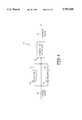
- FIG. 1Dshows one example of an image enhancement imaging apparatus of the invention.
- FIG. 2is an illustrative block diagram showing one method of the invention to deblurr images.
- FIG. 3is a functional block diagram of one embodiment of the method of the invention for enhancing an image.
- FIG. 4shows an example of membership values for dilation, original and erosion images expressed as a function of t.
- FIG. 5shows a functional block diagram of an alternative embodiment of an image enhancement method of the invention.
- FIG. 6shows graphically the functional relationship between g(y) and y for one example embodiment of the method of the invention.
- FIG. 7shows a block diagram of an alternative embodiment of the invention.
- FIG. 8schematically shows the blurred diameter of an optical system for one example embodiment of the invention.
- FIG. 9shows one example of a 3 pixel by 3 pixel cross used for dilation and erosion in one embodiment of the present invention.
- FIG. 10graphically shows a relationship of a kernel, an original signal, a dilated signal, a value of y, and an enhanced signal.
- the automated microscopy apparatus usedis disclosed in a pending U.S. patent application entitled “Method for Identifying Normal Biological Specimens", as discussed herein.
- the system disclosed hereinis used in a system for analyzing cervical pap smears, such as that shown and disclosed in U.S. patent application Ser. No. 07/838,064, entitled “Method For Identifying Normal Biomedical Specimens", by Alan C. Nelson, et al., filed Feb. 18, 1992; U.S. patent application Ser. No. 08/179,812 filed Jan. 10, 1994 which is a continuation in part of U.S. patent application Ser. No. 07/838,395, entitled “Method For Identifying Objects Using Data Processing Techniques", by S. James Lee, et al., filed Feb. 18, 1992; U.S. patent application Ser. No.
- the present inventionis also related to biological and cytological systems as described in the following patent applications which are assigned to the same assignee as the present invention, filed on Sep. 20, 1994 (unless otherwise noted), and which are all hereby incorporated by reference including U.S. patent application Ser. No. 08/309,118 to Kuan et al. entitled, “Field Prioritization Apparatus and Method,” U.S. patent application Ser. No. 08/309,061 to Wilhelm et al., entitled “Apparatus for Automated Identification of Cell Groupings on a Biological Specimen," U.S. patent application Ser. No. 08/309,116 to Meyer et al.
- FIGS. 1A, 1B and 1Cshow a schematic diagram of one embodiment of the apparatus of the invention for image enhancement for biological specimens 500.
- the apparatus of the inventioncomprises an imaging system 502, a motion control system 504, an image processing system 536, a central processing system 540, and a workstation 542.
- the imaging system 502is comprised of an illuminator 508, imaging optics 510, a CCD camera 512, an illumination sensor 514 and an image capture and focus system 516.
- the image capture and focus system 516provides video timing data to the CCD cameras 512, the CCD cameras 512 provide images comprising scan lines to the image capture and focus system 516.
- An illumination sensor intensityis provided to the image capture and focus system 516 where an illumination sensor 514 receives the sample of the image from the optics 510.
- optics 510may comprise color filters.
- the opticsmay further comprise an automated microscope 511.
- the illuminator 508provides illumination of a slide.
- the image capture and focus system 516provides data to a VME bus 538.
- the VME busdistributes the data to an image processing system 536.
- the image processing system 536is comprised of field-of-view processors 568.
- the imagesare sent along the image bus 564 from the image capture and focus system 516.
- a central processor 540controls the operation of the invention through the VME bus 538.
- the central processor 562comprises a MOTOROLA 68030 CPU.
- the motion controller 504is comprised of a tray handler 518, a microscope stage controller 520, a microscope tray controller 522, and a calibration slide 524.
- the motor drivers 526position the slide under the optics.
- a bar code reader 528reads a barcode located on the slide 524.
- a touch sensor 530determines whether a slide is under the microscope objectives, and a door interlock 532 prevents operation in case the doors are open.
- Motion controller 534controls the motor drivers 526 in response to the central processor 540.
- An Ethernet communication system 560communicates to a workstation 542 to provide control of the system.
- a hard disk 544is controlled by workstation 550.
- workstation 550may comprise a workstation.
- a tape drive 546is connected to the workstation 550 as well as a modem 548, a monitor 552, a keyboard 554, and a mouse pointing device 556.
- a printer 558is connected to the ethernet 560.
- the central computer 540controls the microscope 511 and the processor to acquire and digitize images from the microscope 511.
- the flatness of the slidemay be checked, for example, by contacting the four corners of the slide using a computer controlled touch sensor.
- the computer 540also controls the microscope 511 stage to position the specimen under the microscope objective, and from one to fifteen field of view (FOV) processors 568 which receive images under control of the computer 540.
- FOVfield of view
- FIG. 1Dshows one example of an image enhancement imaging apparatus of the invention for an optical system.
- the imaging apparatus 10includes optics 24 and objective 22.
- Drive system 20is connected to stage 16.
- Stage 16holds a slide 18 illuminated by light source 12 through condenser 14.
- the slide 18may comprise, for example, a microscope slide containing a cytological specimen, such as a cervical smear.
- Objective 22views test object on slide 18 and sends light rays through complex optics 24.
- Video camera 26, connected to image acquisition electronics 28,receives the light rays and converts them into electronic signals for processing by image analysis computer 30 connected to image acquisition electronics 28.
- Host processor 32controls motor control electronics 34 which control the drive system 20.
- imaging apparatus 10may comprise conventional devices.
- video camera 26may comprise a standard CCD video camera that may be available, for example, from Sony Corporation of Japan.
- Host processor 32 and/or image analysis computer 30may comprise a conventional microprocessor or other suitable programmable device capable of running software programs.
- the image enhancement method of the inventionmay be embodied, for example, in a software programming language, such as C language, or alternatively, be embedded into an integrated circuit, such as an application specific integrated circuit (ASIC) or any equivalent device capable of performing logic functions necessary for morphological processing of image signals such as erosion (minimum) and dilation (maximum) operations.
- ASICapplication specific integrated circuit
- FIG. 2shows an illustrative block diagram showing one method of the invention to deblurr images.
- a representation in digital form of an original image 38may be provided from image acquisition electronics 28 to the image analysis computer 30 wherein image enhancement apparatus 100 comprises a dilation operation 50, an erosion operation 40 and a combination operation 52.
- the combination operation 52receives the original image 38, a dilated image 56 and an eroded image 58 and responsively produces an enhanced image 54.
- the combination operation 52may be described in terms of a nonlinear fuzzy operation (1).
- I O , I E , I D , and I enhcomprise original, eroded, dilated and enhanced pixel values respectively.
- ⁇ O , ⁇ E and ⁇ Dcomprise membership values for the original, eroded, and dilated images that may be determined for each pixel as functions of the pixel values of the images.
- the membership valuessatisfy the following condition (2).
- the membership valuemay be calculated by the following method. Let ##EQU1## then the membership is ##EQU2## where f(t) is monotonic increasing function, 0 ⁇ f(t) ⁇ 1. For computational efficiency, f(t) can be implemented by a lookup table.
- FIG. 3shows a functional block diagram of one embodiment of the method of the invention for enhancing an image.
- the operation 52comprises membership values 102, 104 and 106 and functional block 108 wherein relationship (3) is performed on the original image, enhanced image and dilated image.
- the dilated, original and eroded images which are multiplied by their membership valuesare summed at summing junction 110 so as to produce an enhanced image 54.
- FIG. 4shows an example of membership values for dilation, original and erosion images expressed as a function of t.
- Curve 120comprises a plot of erosion membership ⁇ E as a function of t.
- Curve 122comprises a plot of original membership ⁇ O as a function of t.
- the above-described method of the inventionprovides a sharper edge than may be present in original images. If the original image has a very sharp edge, the result of this procedure provides an enhanced image almost identical to the original image. In a preferred embodiment, the method of the invention requires that original images exhibit high boundary contrast to produce an enhanced image.
- FIG. 5shows a functional block diagram of an alternative embodiment of an image enhancement method of the invention.
- the alternative embodiment image enhancement methodcomprises the erosion operation 40, the dilation operation 50, a first functional operation 130, a second functional operation 134 and summing operators 132 and 136.
- the alternative embodimentis arranged to implement relationship 5 and relationship 6 as described below.
- g(y)is monotonic increasing function, 0 ⁇ g(y) ⁇ 1.
- g(y)can be implemented by a lookup table.
- FIG. 7shows a block diagram of an alternative embodiment of the invention.
- the original image 38is processed by preprocess operation 39 before a preprocessed image 238 is provided to dilation operation 50 and erosion operation 40 as well as combination operation 52.
- Preprocessing of the original imagemay be desirable if the original image contains noise.
- Preprocessingmay comprise well known image processing methods such as applying a linear filter, a noise reduction filter, a low pass filter, a moving average, or a median filter.
- equations (1)-(6)are applied to the preprocessed pixel images. Hence equations (1) through (3) become
- Equation (4)is now applied to the just described equations. Also, equation (5) becomes ##EQU5## and equation (6) is applied to this value of y.
- FIG. 8schematically shows the blurred diameter of an optical system for one example embodiment of the invention.
- a lens 270focuses on a focal point 272 to produce blurred diameter D at a plane off the focal point 272.
- the blurred diameteris approximately equal to twice the angle N.A. multiplied by delta Z which is the distance between the focal point 272 and the focal plane at the blurred diameter D. If delta Z is about 1 micrometer, and N.A. is 0.6, then D will be about 1.2 micrometers.
- 1.2 micrometersmay comprise about 2 pixels when the magnification is 20 times.
- a kernel size used for dilation and erosionmay be advantageously set at about 3 pixels.
- FIG. 9shows one example of a 3 pixel by 3 pixel cross used for dilation and erosion in one embodiment of the present invention. Dilation and erosion operations may be carried out in a well known manner.
- FIG. 10graphically shows a relationship between a kernel 302, an original signal 304, a dilated signal 306, the value of y, and an enhanced signal 314.
- the different signal 310may be expressed by the difference: I D -I E .
- the y functionmay be expressed as in relationship (11) below. ##EQU6## Note that the enhanced signal 314 has a much sharper edge definition 316 than either the original signal, the dilated signal or the eroded signal.
Landscapes
- Engineering & Computer Science (AREA)
- Physics & Mathematics (AREA)
- General Physics & Mathematics (AREA)
- Theoretical Computer Science (AREA)
- Health & Medical Sciences (AREA)
- Life Sciences & Earth Sciences (AREA)
- Biomedical Technology (AREA)
- General Health & Medical Sciences (AREA)
- Molecular Biology (AREA)
- Multimedia (AREA)
- Image Processing (AREA)
Abstract
Description
I.sub.enh =μ.sub.D I.sub.D +μ.sub.E I.sub.E +μ.sub.O I.sub.O(1)
μ.sub.O +μ.sub.E +μ.sub.D =1 (2)
I.sub.enh =I.sub.E +(μ.sub.D +μ.sub.O y)(I.sub.D -I.sub.E)=I.sub.E +g(y)(I.sub.D -I.sub.E) (6)
I.sub.enh =μ.sub.D I.sub.D +μ.sub.E I.sub.E +μ.sub.p I.sub.p, (7)
μ.sub.p +μ.sub.E +μ.sub.D =1 (8)
Claims (27)
I.sub.enh =μ.sub.D I.sub.D +μ.sub.E I.sub.E +μ.sub.O I.sub.O
μ.sub.O +μ.sub.E +μ.sub.D =1.
I.sub.enh =I.sub.E +(μ.sub.D +μ.sub.O y)(I.sub.D -I.sub.E)=I.sub.E +g(y)(I.sub.D -I.sub.E)
I.sub.enh =μ.sub.D I.sub.D +μ.sub.E I.sub.E +μ.sub.p I.sub.p
μ.sub.p +μ.sub.E +μ.sub.D =1.
I.sub.enh =μ.sub.D I.sub.D +μ.sub.E I.sub.E +μ.sub.O I.sub.O
μ.sub.O +μ.sub.E +μ.sub.D =1.
I.sub.enh =I.sub.E +(μ.sub.D +μ.sub.O y)(I.sub.D -I.sub.E)=I.sub.E +g(y)(I.sub.D -I.sub.E)
Priority Applications (3)
| Application Number | Priority Date | Filing Date | Title |
|---|---|---|---|
| US08/472,389US5787208A (en) | 1995-06-07 | 1995-06-07 | Image enhancement method and apparatus |
| AU59884/96AAU5988496A (en) | 1995-06-07 | 1996-06-06 | Image enhancement method and apparatus |
| PCT/US1996/009189WO1996041301A1 (en) | 1995-06-07 | 1996-06-06 | Image enhancement method and apparatus |
Applications Claiming Priority (1)
| Application Number | Priority Date | Filing Date | Title |
|---|---|---|---|
| US08/472,389US5787208A (en) | 1995-06-07 | 1995-06-07 | Image enhancement method and apparatus |
Publications (1)
| Publication Number | Publication Date |
|---|---|
| US5787208Atrue US5787208A (en) | 1998-07-28 |
Family
ID=23875325
Family Applications (1)
| Application Number | Title | Priority Date | Filing Date |
|---|---|---|---|
| US08/472,389Expired - LifetimeUS5787208A (en) | 1995-06-07 | 1995-06-07 | Image enhancement method and apparatus |
Country Status (3)
| Country | Link |
|---|---|
| US (1) | US5787208A (en) |
| AU (1) | AU5988496A (en) |
| WO (1) | WO1996041301A1 (en) |
Cited By (16)
| Publication number | Priority date | Publication date | Assignee | Title |
|---|---|---|---|---|
| US6457644B1 (en)* | 1998-11-10 | 2002-10-01 | Ncr Corporation | Item checkout device including a bar code data collector and a produce data collector |
| US20030128888A1 (en)* | 2002-01-10 | 2003-07-10 | Sharp Laboratories Of America, Inc. | Nonlinear edge-enhancement filter |
| US20030165263A1 (en)* | 2002-02-19 | 2003-09-04 | Hamer Michael J. | Histological assessment |
| US20030179445A1 (en)* | 1999-10-29 | 2003-09-25 | Garrick Maenle | Cytological imaging systems and methods |
| US20040046102A1 (en)* | 2002-06-03 | 2004-03-11 | Olympus Optical Co.,Ltd. | Image processing apparatus |
| US7062091B2 (en)* | 2001-01-16 | 2006-06-13 | Applied Precision, Llc | Coordinate calibration for scanning systems |
| EP1699016A2 (en) | 2005-02-22 | 2006-09-06 | Microsharp Holdings Limited | Method and apparatus for automated analysis of biological specimen |
| US20070071348A1 (en)* | 2005-09-29 | 2007-03-29 | Samsung Electronics Co., Ltd. | Method and apparatus for bit resolution extension |
| US20070223044A1 (en)* | 2006-03-22 | 2007-09-27 | Bailey James R | Halftone edge enhancement for production by an image forming device |
| US20080262741A1 (en)* | 1998-03-16 | 2008-10-23 | Ge Healthcare Bio-Sciences Corp. | Method and apparatus for screening chemical compounds |
| US20090196524A1 (en)* | 2008-02-05 | 2009-08-06 | Dts Digital Images, Inc. | System and method for sharpening of digital images |
| US20090301047A1 (en)* | 2005-11-30 | 2009-12-10 | Saint-Gobain Centre De Recherches Et D'et Europeen | Method for selecting a gas filtering structure |
| US20100309306A1 (en)* | 2006-03-01 | 2010-12-09 | Hamamatsu Photonics K.K. | Image acquiring apparatus, image acquiring method, and image acquiring program |
| US8131097B2 (en)* | 2008-05-28 | 2012-03-06 | Aptina Imaging Corporation | Method and apparatus for extended depth-of-field image restoration |
| US8514241B2 (en) | 2005-09-29 | 2013-08-20 | Samsung Electronics Co., Ltd. | Method and apparatus for bit resolution extension |
| US20140213900A1 (en)* | 2013-01-29 | 2014-07-31 | Fujifilm Corporation | Ultrasound diagnostic apparatus and method of producing ultrasound image |
Families Citing this family (1)
| Publication number | Priority date | Publication date | Assignee | Title |
|---|---|---|---|---|
| JP5395507B2 (en) | 2009-05-21 | 2014-01-22 | キヤノン株式会社 | Three-dimensional shape measuring apparatus, three-dimensional shape measuring method, and computer program |
Citations (23)
| Publication number | Priority date | Publication date | Assignee | Title |
|---|---|---|---|---|
| US3824393A (en)* | 1971-08-25 | 1974-07-16 | American Express Invest | System for differential particle counting |
| US4034342A (en)* | 1974-12-23 | 1977-07-05 | Burroughs Corporation | Magnetic character recognition system employing a dynamic threshold voltage determination system |
| US4175860A (en)* | 1977-05-31 | 1979-11-27 | Rush-Presbyterian-St. Luke's Medical Center | Dual resolution method and apparatus for use in automated classification of pap smear and other samples |
| US4523278A (en)* | 1979-02-01 | 1985-06-11 | Prof. Dr.-Ing. Werner H. Bloss | Method of automatic detection of cells and determination of cell features from cytological smear preparations |
| US4783751A (en)* | 1983-08-17 | 1988-11-08 | University Of South Carolina | Analysis of pore complexes |
| US4866785A (en)* | 1985-12-27 | 1989-09-12 | International Business Machines Corporation | Multi-valved image processing apparatus and method |
| US4965725A (en)* | 1988-04-08 | 1990-10-23 | Nueromedical Systems, Inc. | Neural network based automated cytological specimen classification system and method |
| US5029226A (en)* | 1989-10-10 | 1991-07-02 | Unisys Corporation | Method and apparatus for effecting spot/void filtering of image data |
| US5072382A (en)* | 1989-10-02 | 1991-12-10 | Kamentsky Louis A | Methods and apparatus for measuring multiple optical properties of biological specimens |
| US5172420A (en)* | 1991-05-28 | 1992-12-15 | At&T Bell Laboratories | Method for monitoring the dimensions and other aspects linewidth thickness and discoloration of specular patterns |
| US5201011A (en)* | 1991-11-19 | 1993-04-06 | Xerox Corporation | Method and apparatus for image hand markup detection using morphological techniques |
| US5202933A (en)* | 1989-12-08 | 1993-04-13 | Xerox Corporation | Segmentation of text and graphics |
| US5257182A (en)* | 1991-01-29 | 1993-10-26 | Neuromedical Systems, Inc. | Morphological classification system and method |
| US5315700A (en)* | 1992-02-18 | 1994-05-24 | Neopath, Inc. | Method and apparatus for rapidly processing data sequences |
| US5361140A (en)* | 1992-02-18 | 1994-11-01 | Neopath, Inc. | Method and apparatus for dynamic correction of microscopic image signals |
| US5392137A (en)* | 1992-04-30 | 1995-02-21 | Ricoh Company, Ltd. | Image processing apparatus in which filtering is selected for input image characteristics |
| US5577131A (en)* | 1993-05-05 | 1996-11-19 | U.S. Philips Corporation | Device for segmenting textured images and image segmentation system comprising such a device |
| US5579445A (en)* | 1993-12-17 | 1996-11-26 | Xerox Corporation | Image resolution conversion method that employs statistically generated multiple morphological filters |
| US5586160A (en)* | 1995-03-20 | 1996-12-17 | The Regents Of The University Of California | Automated analysis for microcalcifications in high resolution digital mammograms |
| US5598481A (en)* | 1994-04-29 | 1997-01-28 | Arch Development Corporation | Computer-aided method for image feature analysis and diagnosis in mammography |
| US5615314A (en)* | 1994-08-30 | 1997-03-25 | Management Graphics, Inc. | Interface for providing rasterized data to an imaging device |
| US5627908A (en)* | 1994-09-20 | 1997-05-06 | Neopath, Inc. | Method for cytological system dynamic normalization |
| US5647025A (en)* | 1994-09-20 | 1997-07-08 | Neopath, Inc. | Automatic focusing of biomedical specimens apparatus |
- 1995
- 1995-06-07USUS08/472,389patent/US5787208A/ennot_activeExpired - Lifetime
- 1996
- 1996-06-06WOPCT/US1996/009189patent/WO1996041301A1/enactiveApplication Filing
- 1996-06-06AUAU59884/96Apatent/AU5988496A/ennot_activeAbandoned
Patent Citations (27)
| Publication number | Priority date | Publication date | Assignee | Title |
|---|---|---|---|---|
| US3824393A (en)* | 1971-08-25 | 1974-07-16 | American Express Invest | System for differential particle counting |
| US4034342A (en)* | 1974-12-23 | 1977-07-05 | Burroughs Corporation | Magnetic character recognition system employing a dynamic threshold voltage determination system |
| US4175860A (en)* | 1977-05-31 | 1979-11-27 | Rush-Presbyterian-St. Luke's Medical Center | Dual resolution method and apparatus for use in automated classification of pap smear and other samples |
| US4523278A (en)* | 1979-02-01 | 1985-06-11 | Prof. Dr.-Ing. Werner H. Bloss | Method of automatic detection of cells and determination of cell features from cytological smear preparations |
| US4783751A (en)* | 1983-08-17 | 1988-11-08 | University Of South Carolina | Analysis of pore complexes |
| US4866785A (en)* | 1985-12-27 | 1989-09-12 | International Business Machines Corporation | Multi-valved image processing apparatus and method |
| US4965725B1 (en)* | 1988-04-08 | 1996-05-07 | Neuromedical Systems Inc | Neural network based automated cytological specimen classification system and method |
| US5287272A (en)* | 1988-04-08 | 1994-02-15 | Neuromedical Systems, Inc. | Automated cytological specimen classification system and method |
| US5287272B1 (en)* | 1988-04-08 | 1996-08-27 | Neuromedical Systems Inc | Automated cytological specimen classification system and method |
| US4965725A (en)* | 1988-04-08 | 1990-10-23 | Nueromedical Systems, Inc. | Neural network based automated cytological specimen classification system and method |
| US5072382A (en)* | 1989-10-02 | 1991-12-10 | Kamentsky Louis A | Methods and apparatus for measuring multiple optical properties of biological specimens |
| US5029226A (en)* | 1989-10-10 | 1991-07-02 | Unisys Corporation | Method and apparatus for effecting spot/void filtering of image data |
| US5202933A (en)* | 1989-12-08 | 1993-04-13 | Xerox Corporation | Segmentation of text and graphics |
| US5257182B1 (en)* | 1991-01-29 | 1996-05-07 | Neuromedical Systems Inc | Morphological classification system and method |
| US5257182A (en)* | 1991-01-29 | 1993-10-26 | Neuromedical Systems, Inc. | Morphological classification system and method |
| US5172420A (en)* | 1991-05-28 | 1992-12-15 | At&T Bell Laboratories | Method for monitoring the dimensions and other aspects linewidth thickness and discoloration of specular patterns |
| US5201011A (en)* | 1991-11-19 | 1993-04-06 | Xerox Corporation | Method and apparatus for image hand markup detection using morphological techniques |
| US5315700A (en)* | 1992-02-18 | 1994-05-24 | Neopath, Inc. | Method and apparatus for rapidly processing data sequences |
| US5361140A (en)* | 1992-02-18 | 1994-11-01 | Neopath, Inc. | Method and apparatus for dynamic correction of microscopic image signals |
| US5392137A (en)* | 1992-04-30 | 1995-02-21 | Ricoh Company, Ltd. | Image processing apparatus in which filtering is selected for input image characteristics |
| US5577131A (en)* | 1993-05-05 | 1996-11-19 | U.S. Philips Corporation | Device for segmenting textured images and image segmentation system comprising such a device |
| US5579445A (en)* | 1993-12-17 | 1996-11-26 | Xerox Corporation | Image resolution conversion method that employs statistically generated multiple morphological filters |
| US5598481A (en)* | 1994-04-29 | 1997-01-28 | Arch Development Corporation | Computer-aided method for image feature analysis and diagnosis in mammography |
| US5615314A (en)* | 1994-08-30 | 1997-03-25 | Management Graphics, Inc. | Interface for providing rasterized data to an imaging device |
| US5627908A (en)* | 1994-09-20 | 1997-05-06 | Neopath, Inc. | Method for cytological system dynamic normalization |
| US5647025A (en)* | 1994-09-20 | 1997-07-08 | Neopath, Inc. | Automatic focusing of biomedical specimens apparatus |
| US5586160A (en)* | 1995-03-20 | 1996-12-17 | The Regents Of The University Of California | Automated analysis for microcalcifications in high resolution digital mammograms |
Non-Patent Citations (32)
| Title |
|---|
| Bacus, James W. and Les J. Grace, "Optical Microscope System For Standardized Cell Measurements and Analyses", Applied Optics, 26:16, pp. 3280-3292, 15 Aug. 1987. |
| Bacus, James W. and Les J. Grace, Optical Microscope System For Standardized Cell Measurements and Analyses , Applied Optics , 26:16, pp. 3280 3292, 15 Aug. 1987.* |
| Bartels, Peter H., et al., "A Self-Learning Computer Program for Cell Recognition", ACTA Cytologica: The Journal of Clinical Cytology, 14:8, pp. 486-494, Oct. 1970. |
| Bartels, Peter H., et al., A Self Learning Computer Program for Cell Recognition , ACTA Cytologica: The Journal of Clinical Cytology , 14:8, pp. 486 494, Oct. 1970.* |
| Duda, Richard O. and Peter E. Hart, "Fisher's Linear Discriminant", Patent Classification and Scene Analysis, Copyright ©1973, pp. 114-119. |
| Duda, Richard O. and Peter E. Hart, Fisher s Linear Discriminant , Patent Classification and Scene Analysis , Copyright 1973, pp. 114 119.* |
| Dytch, Harvey E. et al., "An Interactive Microcomputer-Based System for the Quantitative Analysis of Stratified Tissue Sections", Analytical and Quantitative Cytology and Histology, vol. 9, No. 1, pp. 69-78, Mar. 1987. |
| Dytch, Harvey E. et al., An Interactive Microcomputer Based System for the Quantitative Analysis of Stratified Tissue Sections , Analytical and Quantitative Cytology and Histology , vol. 9, No. 1, pp. 69 78, Mar. 1987.* |
| Enslein, Kurt and Peter W. Neurath, "Augmented Stepwise Discriminant Analysis Applied to Two Classification Problems in the Biomedical Field", Computers and Biomedical Research, 2, 568-581 (1969). |
| Enslein, Kurt and Peter W. Neurath, Augmented Stepwise Discriminant Analysis Applied to Two Classification Problems in the Biomedical Field , Computers and Biomedical Research , 2, 568 581 (1969).* |
| Kurman, Robert J. et al., "Part 1: Specimen Adequacy" and Part 2: Descriptive Diagnoses, The Bethesda System for Reporting Cervical/Vaginal Cytologic Diagnoses, ©Springer-Verlage; 1994. |
| Kurman, Robert J. et al., Part 1: Specimen Adequacy and Part 2: Descriptive Diagnoses, The Bethesda System for Reporting Cervical/Vaginal Cytologic Diagnoses , Springer Verlage; 1994.* |
| Patten, Jr., Stanley, "Diagnostic Cytopathology of the Uterine Cervix", Basel, Switzerland, Publisher: S. Karger, 1969, 2nd Edition 1978, Third volume in Monographs in Clinical Cytology, edited by G.L. Wied, pp. 10-15. |
| Patten, Jr., Stanley, Diagnostic Cytopathology of the Uterine Cervix , Basel, Switzerland, Publisher: S. Karger, 1969, 2nd Edition 1978, Third volume in Monographs in Clinical Cytology , edited by G.L. Wied, pp. 10 15.* |
| Serra, J., Image Analysis and Mathematical Morphology , pp. 372 423, Academic Press, 1982.* |
| Serra, J., Image Analysis and Mathematical Morphology, pp. 372-423, Academic Press, 1982. |
| Smith, Warren J., "Modern Optical Engineering: The Design of Optical Systems", Copyright ©1966 by McGraw-Hill Book Company, pp. 308-325. |
| Smith, Warren J., Modern Optical Engineering: The Design of Optical Systems , Copyright 1966 by McGraw Hill Book Company, pp. 308 325.* |
| Tanaka, Noboru, et al., "Automated Cytologic Screening System (CYBEST Model 4): an Integrated Image Cytometry System", Reprinted from Applied Optics, vol. 26, No. 16, pp. 3301-3307, Aug. 15, 1987. Copyright© 1987 by the Optical Society of America and reprinted by permission of the copyright owner. |
| Tanaka, Noboru, et al., Automated Cytologic Screening System (CYBEST Model 4): an Integrated Image Cytometry System , Reprinted from Applied Optics , vol. 26, No. 16, pp. 3301 3307, Aug. 15, 1987. Copyright 1987 by the Optical Society of America and reprinted by permission of the copyright owner.* |
| Weber, J.E. et al., "Fuzzy Reasoning, Possibility Theory and Probability Theory in Expert Systems for Histopathology", Proceedings, 9th Annual IEEE Conference on Engineering in Medicine and Biomedical Sciences, Boston, pp. 1560-1561, ©1987. |
| Weber, J.E. et al., Fuzzy Reasoning, Possibility Theory and Probability Theory in Expert Systems for Histopathology , Proceedings, 9th Annual IEEE Conference on Engineering in Medicine and Biomedical Sciences, Boston, pp. 1560 1561, 1987.* |
| Wied, G.L. et al., "Expert System Design Under Uncertainty of Human Diagnosticians", IEEE/Eighth Annual Conference of the Engineering in Medicine and Biology Society, pp. 757-760, ©1986. |
| Wied, G.L. et al., "Expert Systems as Classifiers in Diagnostic Cytopathology", IEEE/Ninth Annual Conference of the Engineering in Medicine and Biology Society, pp. 1915-1917, ©1987. |
| Wied, G.L. et al., "Ticas-Stratex, an Expert Diagnostic System For Stratified Cervical Epithelium", IEEE/Ninth Annual Conference of the Engineering in Medicine and Biology Society, pp. 1557-1559, ©1987. |
| Wied, G.L. et al., Expert System Design Under Uncertainty of Human Diagnosticians , IEEE/Eighth Annual Conference of the Engineering in Medicine and Biology Society, pp. 757 760, 1986.* |
| Wied, G.L. et al., Expert Systems as Classifiers in Diagnostic Cytopathology , IEEE/Ninth Annual Conference of the Engineering in Medicine and Biology Society, pp. 1915 1917, 1987.* |
| Wied, G.L. et al., Ticas Stratex, an Expert Diagnostic System For Stratified Cervical Epithelium , IEEE/Ninth Annual Conference of the Engineering in Medicine and Biology Society, pp. 1557 1559, 1987.* |
| Yoda, H. et al., "An Automatic Wafer Inspection System Using Pipeline Image Processing Techniques", IEEE Transaction on Pattern Analysis and Machine Intelligence, vol. 10, No. 1, issued Jan. 1988. |
| Yoda, H. et al., An Automatic Wafer Inspection System Using Pipeline Image Processing Techniques , IEEE Transaction on Pattern Analysis and Machine Intelligence, vol. 10, No. 1, issued Jan. 1988.* |
| Zamperoni, "Variations on the Rank-Order Filtering Theme for Grey-Tone and Binary Image Enhancement" IEEE Publication issued 1989, pp. 1401-1404. |
| Zamperoni, Variations on the Rank Order Filtering Theme for Grey Tone and Binary Image Enhancement IEEE Publication issued 1989, pp. 1401 1404.* |
Cited By (35)
| Publication number | Priority date | Publication date | Assignee | Title |
|---|---|---|---|---|
| US20080262741A1 (en)* | 1998-03-16 | 2008-10-23 | Ge Healthcare Bio-Sciences Corp. | Method and apparatus for screening chemical compounds |
| US7957911B2 (en)* | 1998-03-16 | 2011-06-07 | Ge Healthcare Bio-Sciences Corp. | Method and apparatus for screening chemical compounds |
| US6457644B1 (en)* | 1998-11-10 | 2002-10-01 | Ncr Corporation | Item checkout device including a bar code data collector and a produce data collector |
| US7667890B2 (en) | 1999-10-29 | 2010-02-23 | Cytyc Corporation | Cytological imaging systems and methods |
| US7468836B2 (en) | 1999-10-29 | 2008-12-23 | Cytyc Corporation | Cytological imaging systems and methods |
| US20100128944A1 (en)* | 1999-10-29 | 2010-05-27 | Cytyc Corporation | Cytological imaging systems and methods |
| US20060077538A1 (en)* | 1999-10-29 | 2006-04-13 | Cytyc Corporation | Cytological imaging systems and methods |
| US20060077541A1 (en)* | 1999-10-29 | 2006-04-13 | Cytyc Corporation | Cytological imaging systems and methods |
| US20030179445A1 (en)* | 1999-10-29 | 2003-09-25 | Garrick Maenle | Cytological imaging systems and methods |
| US7369304B2 (en) | 1999-10-29 | 2008-05-06 | Cytyc Corporation | Cytological autofocusing imaging systems and methods |
| US20080018994A1 (en)* | 1999-10-29 | 2008-01-24 | Cytyc Corporation | Cytological imaging systems and methods |
| US7446935B2 (en) | 1999-10-29 | 2008-11-04 | Cytyc Corporation | Cytological imaging systems and methods |
| US20080013812A1 (en)* | 1999-10-29 | 2008-01-17 | Cytyc Corporation | Cytological imaging systems and methods |
| US20080013168A1 (en)* | 1999-10-29 | 2008-01-17 | Cytyc Corporation | Cytological imaging systems and methods |
| US7062091B2 (en)* | 2001-01-16 | 2006-06-13 | Applied Precision, Llc | Coordinate calibration for scanning systems |
| US20030128888A1 (en)* | 2002-01-10 | 2003-07-10 | Sharp Laboratories Of America, Inc. | Nonlinear edge-enhancement filter |
| US6873741B2 (en) | 2002-01-10 | 2005-03-29 | Sharp Laboratories Of America | Nonlinear edge-enhancement filter |
| US20030165263A1 (en)* | 2002-02-19 | 2003-09-04 | Hamer Michael J. | Histological assessment |
| US20040046102A1 (en)* | 2002-06-03 | 2004-03-11 | Olympus Optical Co.,Ltd. | Image processing apparatus |
| US7084383B2 (en)* | 2002-06-03 | 2006-08-01 | Olympus Corporation | Image processing apparatus |
| US20060204953A1 (en)* | 2005-02-22 | 2006-09-14 | Nikolai Ptitsyn | Method and apparatus for automated analysis of biological specimen |
| EP1699016A2 (en) | 2005-02-22 | 2006-09-06 | Microsharp Holdings Limited | Method and apparatus for automated analysis of biological specimen |
| US7734109B2 (en) | 2005-09-29 | 2010-06-08 | Samsung Electronics Co., Ltd. | Method and apparatus for bit resolution extension |
| US8514241B2 (en) | 2005-09-29 | 2013-08-20 | Samsung Electronics Co., Ltd. | Method and apparatus for bit resolution extension |
| US20070071348A1 (en)* | 2005-09-29 | 2007-03-29 | Samsung Electronics Co., Ltd. | Method and apparatus for bit resolution extension |
| US8066798B2 (en)* | 2005-11-30 | 2011-11-29 | Saint-Gobain Centre De Recherches Et D'etudes European | Method for selecting a gas filtering structure |
| US20090301047A1 (en)* | 2005-11-30 | 2009-12-10 | Saint-Gobain Centre De Recherches Et D'et Europeen | Method for selecting a gas filtering structure |
| US20100309306A1 (en)* | 2006-03-01 | 2010-12-09 | Hamamatsu Photonics K.K. | Image acquiring apparatus, image acquiring method, and image acquiring program |
| US7978898B2 (en)* | 2006-03-01 | 2011-07-12 | Hamamatsu Photonics K.K. | Image acquiring apparatus, image acquiring method, and image acquiring program |
| US7602531B2 (en) | 2006-03-22 | 2009-10-13 | Lexmark International, Inc. | Halftone edge enhancement for production by an image forming device |
| US20070223044A1 (en)* | 2006-03-22 | 2007-09-27 | Bailey James R | Halftone edge enhancement for production by an image forming device |
| US20090196524A1 (en)* | 2008-02-05 | 2009-08-06 | Dts Digital Images, Inc. | System and method for sharpening of digital images |
| US8131097B2 (en)* | 2008-05-28 | 2012-03-06 | Aptina Imaging Corporation | Method and apparatus for extended depth-of-field image restoration |
| US20140213900A1 (en)* | 2013-01-29 | 2014-07-31 | Fujifilm Corporation | Ultrasound diagnostic apparatus and method of producing ultrasound image |
| US11074693B2 (en)* | 2013-01-29 | 2021-07-27 | Fujifilm Corporation | Ultrasound diagnostic apparatus and method of producing ultrasound image |
Also Published As
| Publication number | Publication date |
|---|---|
| AU5988496A (en) | 1996-12-30 |
| WO1996041301A1 (en) | 1996-12-19 |
Similar Documents
| Publication | Publication Date | Title |
|---|---|---|
| US5787208A (en) | Image enhancement method and apparatus | |
| US5642433A (en) | Method and apparatus for image contrast quality evaluation | |
| US5787189A (en) | Biological analysis system self calibration apparatus | |
| US6252979B1 (en) | Interactive method and apparatus for sorting biological specimens | |
| US5528703A (en) | Method for identifying objects using data processing techniques | |
| US5757954A (en) | Field prioritization apparatus and method | |
| US5566249A (en) | Apparatus for detecting bubbles in coverslip adhesive | |
| US5287272A (en) | Automated cytological specimen classification system and method | |
| US5790692A (en) | Method and means of least squares designed filters for image segmentation in scanning cytometry | |
| US5978497A (en) | Apparatus for the identification of free-lying cells | |
| US20020186874A1 (en) | Method and means for image segmentation in fluorescence scanning cytometry | |
| US5715327A (en) | Method and apparatus for detection of unsuitable conditions for automated cytology scoring | |
| WO1996009600A1 (en) | Apparatus for identification and integration of multiple cell patterns | |
| JPH10506206A (en) | Automatic focusing device for medical and biological specimens | |
| WO1996009603A1 (en) | Method and apparatus for robust biological specimen classification | |
| EP0782735A1 (en) | Cytological system image collection integrity checking apparatus | |
| US5991432A (en) | Cytological system illumination integrity checking apparatus and method | |
| WO1991006911A1 (en) | Automated cytological specimen classification system and method | |
| WO2000062241A1 (en) | Method and apparatus for determining microscope specimen preparation type | |
| WO1997004348A1 (en) | Automatic focus system | |
| WO2000062240A1 (en) | Automatic slide classification using microscope slide preparation type | |
| WO1999001985A1 (en) | Method and apparatus for semiconductor wafer and lcd inspection using multidimensional image decomposition and synthesis | |
| AU721417C (en) | Cytological system image collection integrity checking apparatus | |
| Sobrevilla et al. | An approach to a fuzzy-based automatic pap screening system-FAPSS-addressed to cytology cells detection | |
| Bravo-Zanoguera et al. | Analog autofocus circuit design for scanning microscopy |
Legal Events
| Date | Code | Title | Description |
|---|---|---|---|
| AS | Assignment | Owner name:NEOPATH, INC., WASHINGTON Free format text:ASSIGNMENT OF ASSIGNORS INTEREST;ASSIGNORS:OH, SEHO;LEE, SHIH-JONG J.;KUAN, CHIH-CHAU L.;AND OTHERS;REEL/FRAME:007595/0608 Effective date:19950712 | |
| FEPP | Fee payment procedure | Free format text:PAYOR NUMBER ASSIGNED (ORIGINAL EVENT CODE: ASPN); ENTITY STATUS OF PATENT OWNER: LARGE ENTITY | |
| STCF | Information on status: patent grant | Free format text:PATENTED CASE | |
| AS | Assignment | Owner name:C/O MEIER MITCHELL & COMPANY, CALIFORNIA Free format text:SECURITY AGREEMENT;ASSIGNOR:TRIPATH IMAGING, INC., A DELAWARE CORPORATION;REEL/FRAME:010526/0422 Effective date:20000119 | |
| AS | Assignment | Owner name:SILICON VALLEY BANK, CALIFORNIA Free format text:SECURITY INTEREST;ASSIGNOR:AUTOCYTE NORTH CAROLINA, LLC;REEL/FRAME:010696/0502 Effective date:20000131 | |
| AS | Assignment | Owner name:SILICON VALLEY BANK, GEORGIA Free format text:SECURITY AGREEMENT;ASSIGNOR:TRIPATH IMAGING, INC., A CORP. OF DELAWARE;REEL/FRAME:011064/0195 Effective date:20000131 | |
| FPAY | Fee payment | Year of fee payment:4 | |
| AS | Assignment | Owner name:TRIPATH IMAGING, INC., NORTH CAROLINA Free format text:TERMINATION OF SECURITY INTEREST;ASSIGNOR:MMC/GATX PARTNERSHIP NO. I TRANSAMERICA BUSINESS CREDIT CORPORATION;REEL/FRAME:014567/0155 Effective date:20030404 | |
| FPAY | Fee payment | Year of fee payment:8 | |
| AS | Assignment | Owner name:TRIPATH IMAGING, INC., NORTH CAROLINA Free format text:MERGER;ASSIGNOR:NEOPATH, INC.;REEL/FRAME:018207/0099 Effective date:19991223 | |
| AS | Assignment | Owner name:TRIPATH IMAGING, INC., NORTH CAROLINA Free format text:RELEASE OF SECURITY AGREEMENT;ASSIGNOR:SILICON VALLEY BANK;REEL/FRAME:018207/0475 Effective date:20060829 Owner name:AUTOCYTE NORTH CAROLINA, INC., NORTH CAROLINA Free format text:RELEASE OF SECURITY AGREEMENT;ASSIGNOR:SILICON VALLEY BANK;REEL/FRAME:018207/0441 Effective date:20060830 | |
| FEPP | Fee payment procedure | Free format text:PAYER NUMBER DE-ASSIGNED (ORIGINAL EVENT CODE: RMPN); ENTITY STATUS OF PATENT OWNER: LARGE ENTITY Free format text:PAYOR NUMBER ASSIGNED (ORIGINAL EVENT CODE: ASPN); ENTITY STATUS OF PATENT OWNER: LARGE ENTITY Free format text:PAT HOLDER NO LONGER CLAIMS SMALL ENTITY STATUS, ENTITY STATUS SET TO UNDISCOUNTED (ORIGINAL EVENT CODE: STOL); ENTITY STATUS OF PATENT OWNER: LARGE ENTITY | |
| FPAY | Fee payment | Year of fee payment:12 |