US5787100A - Apparatus for determining error evaluator polynomial for use in a Reed-Solomon decoder - Google Patents
Apparatus for determining error evaluator polynomial for use in a Reed-Solomon decoderDownload PDFInfo
- Publication number
- US5787100A US5787100AUS08/810,502US81050297AUS5787100AUS 5787100 AUS5787100 AUS 5787100AUS 81050297 AUS81050297 AUS 81050297AUS 5787100 AUS5787100 AUS 5787100A
- Authority
- US
- United States
- Prior art keywords
- sub
- output
- providing
- error
- polynomial
- Prior art date
- Legal status (The legal status is an assumption and is not a legal conclusion. Google has not performed a legal analysis and makes no representation as to the accuracy of the status listed.)
- Expired - Lifetime
Links
- 208000011580syndromic diseaseDiseases0.000claimsabstractdescription24
- 230000015654memoryEffects0.000claimsabstractdescription17
- 238000000034methodMethods0.000description11
- 230000004044responseEffects0.000description10
- 238000010586diagramMethods0.000description6
- 101001018097Homo sapiens L-selectinProteins0.000description5
- 102100033467L-selectinHuman genes0.000description5
- 101100422768Saccharomyces cerevisiae (strain ATCC 204508 / S288c) SUL2 geneProteins0.000description3
- 101100191136Arabidopsis thaliana PCMP-A2 geneProteins0.000description1
- 101100048260Saccharomyces cerevisiae (strain ATCC 204508 / S288c) UBX2 geneProteins0.000description1
- 238000011156evaluationMethods0.000description1
- 230000014509gene expressionEffects0.000description1
- 238000004519manufacturing processMethods0.000description1
- 238000012986modificationMethods0.000description1
- 230000004048modificationEffects0.000description1
- 230000000630rising effectEffects0.000description1
- 230000001960triggered effectEffects0.000description1
Images

Classifications
- H—ELECTRICITY
- H03—ELECTRONIC CIRCUITRY
- H03M—CODING; DECODING; CODE CONVERSION IN GENERAL
- H03M13/00—Coding, decoding or code conversion, for error detection or error correction; Coding theory basic assumptions; Coding bounds; Error probability evaluation methods; Channel models; Simulation or testing of codes
- H03M13/03—Error detection or forward error correction by redundancy in data representation, i.e. code words containing more digits than the source words
- H03M13/05—Error detection or forward error correction by redundancy in data representation, i.e. code words containing more digits than the source words using block codes, i.e. a predetermined number of check bits joined to a predetermined number of information bits
- H03M13/13—Linear codes
- H03M13/15—Cyclic codes, i.e. cyclic shifts of codewords produce other codewords, e.g. codes defined by a generator polynomial, Bose-Chaudhuri-Hocquenghem [BCH] codes
- H03M13/151—Cyclic codes, i.e. cyclic shifts of codewords produce other codewords, e.g. codes defined by a generator polynomial, Bose-Chaudhuri-Hocquenghem [BCH] codes using error location or error correction polynomials
Definitions
- a set of check bitsis appended to a group of message or information bits to form a codeword.
- the check bitswhich are determined by an encoder, are used to detect and correct the errors.
- the encoderessentially treats the bits comprising the message bits as coefficients of a binary message polynomial and derives the check bits by multiplying the message polynomial i(X) with a code generating polynomial g(X) or dividing i(X) by g(x), to thereby provide a codeword polynomial c(X).
- error correcting codesis the well-known BCH (Bose-Chaudhuri-Hocquenghen) code class, which includes the Reed-Solomon ("RS") code.
- BCHReed-Solomon
- the mathematical basis of the RS codeis explained in, e.g., the aforementioned reference by Lin et al. and also in Berlekamp, "Algebraic Coding Theory", McGraw-Hill, 1968, which is further referred to in U.S. Pat. No. 4,162,480 issued to Berlekamp.
- ⁇ -ja power of the primary element, ⁇ -j , for a variable X in the error locator polynomial ⁇ (X) results in 0 (i.e., ⁇ -j becomes a root of ⁇ (X)), it means that an error has occurred in r j , i.e., a (N-j)th symbol of a codeword.
- error valuesare calculated by using the error locations and the syndromes.
- Mathematical expressions for the syndromes and the coefficients of the error locator polynomialare set forth in the afore-referenced U.S. Pat. No. 4,162,480 issued to Berlekamp.
- an error evaluator polynomial ⁇ (X)may be obtained as follows:
- Eq. (2)may be restated as: ##EQU3##
- SRi's and CRi'sare updated as shown in Tables 1 and 2.
- a first columnrepresents a step number, wherein each step may correspond to one system clock cycle. It should be noted that S 0 equals 1 and, therefore, replaced as 1 in the Tables.
- S iis an (i)th syndrome value
- ⁇ iis an (i)th coefficient of an error locator polynomial
- a coefficient input blockfor sequentially providing the coefficients of the error locator polynomial as a first output and the syndrome values as a second output in a predetermined order;
- a multiplierfor sequentially multiplying the first output and the second output provided from the coefficient input block, to thereby sequentially provide multiplication results
- a first multiplexorfor providing contents of one of the T memories in a predefined order
- an adderfor adding each of the multiplication results provided from the multiplier to the contents of one of the T memories provided from the multiplexor, to thereby provide an addition result
- a second multiplexorfor selectively providing the first output or the addition result
- a demultiplexorfor providing the first output or the addition result provided from the second multiplexor to one of the T memories, to be stored therein.
- FIG. 1shows a block diagram of a conventional error evaluator polynomial calculating apparatus
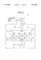
- FIG. 2represents a block diagram of an error evaluator polynomial calculating apparatus in accordance with a first embodiment of the present invention.
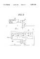
- FIG. 3illustrates a block diagram of an error evaluator polynomial calculating apparatus in accordance with a second embodiment of the present invention.
- the error evaluator polynomial calculating apparatus 2includes a GF multiplier 11 and a GF adder 13 which directly correspond to the GF multipliers 41 to 45 and the GF adders 61 to 65 shown in FIG. 1, respectively. It further includes a register block 15 which corresponds to the registers CR1 to CR5 shown in FIG.
- the structure of the error evaluator polynomial calculating apparatus 3 shown in FIG. 3is substantially same as that of FIG. 2. However, unlike the apparatus 2 shown in FIG. 2, the register block 35 includes 4 registers (R0 to R3) connected in serial. The apparatus 3 shown in FIG. 3 also provides first to fourth coefficients, ⁇ 1 to ⁇ 4 , of the error evaluator polynomial.
- the registers R0 to R3are initialized with the coefficients of the error locator polynomial ⁇ 4 to ⁇ 1 , respectively.
- a coefficient input block 30sequentially provides ⁇ 1 to ⁇ 4 as a first output, i.e., ⁇ i , to a MUX 37; and the MUX 37 sequentially provides the coefficients to R0 in response to a control signal SEL.
- SELcontrols the MUX 37 to select the output of the coefficient input block 30 on an input port 1 during the initialization, and to select the output of the GF adder 33 on an input port 0 otherwise.
- the contents of the registersare shifted right so that R0 to R3 store ⁇ 4 to ⁇ 1 , respectively.
- the coefficient input block 30provides ⁇ 0 , i.e., 1, as the first output, ⁇ i , and S 1 as the second output, S j , to the GF multiplier 31 wherein they are multiplied to provide ⁇ 0 S 1 , i.e., S 1 , to the GF adder 33.
- the content of R3, ⁇ 1is also provided to the GF adder 33.
- the GF adder 33provides an addition result, S 1 + ⁇ 1 to the MUX 37.
- the MUX 37selects the addition result in response to SEL and provides it to R0, to be stored therein, and the contents of registers are shifted right.
- the contents of R0 to R3become S 1 + ⁇ 1 , ⁇ 4 , ⁇ 3 and ⁇ 2 , respectively.
Landscapes
- Physics & Mathematics (AREA)
- Mathematical Physics (AREA)
- Algebra (AREA)
- General Physics & Mathematics (AREA)
- Pure & Applied Mathematics (AREA)
- Probability & Statistics with Applications (AREA)
- Engineering & Computer Science (AREA)
- Theoretical Computer Science (AREA)
- Error Detection And Correction (AREA)
- Detection And Correction Of Errors (AREA)
Abstract
Description
Ω(X)=σ(X)S(X) Eq. (2)
TABLE 1 ______________________________________ SR1 SR2 SR3 SR4 SR5 ______________________________________ 1 1 S.sub.1 S.sub.2 S.sub.3 S.sub.4 2 0 1 S.sub.1 S.sub.2 S.sub.3 3 0 0 1 S.sub.1 S.sub.2 4 0 0 0 1 S.sub.1 5 0 0 0 0 1 ______________________________________
TABLE 2 __________________________________________________________________________CR1 CR2 CR3 CR4 CR5 __________________________________________________________________________1 1 S.sub.1 S.sub.2 S.sub.3 S.sub.4 2 1 σ.sub.1 + S.sub.1 S.sub.2 + σ.sub.1 S.sub.1 S.sub.3 + σ.sub.1 S.sub.2 S.sub.4 + σ.sub.1 S.sub.3 3 1 σ.sub.1 + S.sub.1 S.sub.2 + σ.sub.1 S.sub.1 + σ.sub.2 S.sub.3 + σ.sub.1 S.sub.2 + σ.sub.2 S.sub.1 S.sub.4 + σ.sub.1 S.sub.3 + σ.sub.2 S.sub.2 4 1 σ.sub.1 + S.sub.1 S.sub.2 + σ.sub.1 S.sub.1 + σ.sub.2 S.sub.3 + σ.sub.1 S.sub.2 + σ.sub.2 S.sub.1 + σ.sub.3 S.sub.4 + σ.sub.1 S.sub.3 + σ.sub.2 S.sub.2 + σ.sub.3 S.sub.1 5 1 σ.sub.1 + S.sub.1 S.sub.2 + σ.sub.1 S.sub.1 + σ.sub.2 S.sub.3 + σ.sub.1 S.sub.2 + σ.sub.2 S.sub.1 + σ.sub.3 S.sub.4 + σ.sub.1 S.sub.3 + σ.sub.2 S.sub.2 + σ.sub.3 S.sub.1 + σ.sub.4 __________________________________________________________________________
Ω(X)=1+(S.sub.1 +σ.sub.1)X+(S.sub.2 +S.sub.1 σ.sub.1 +σ.sub.2)X.sup.2 + . . . +(S.sub.T S.sub.T-1 σ.sub.1 +S.sub.T-2 σ.sub.2 + . . . +σ.sub.T)X.sup.T
TABLE 3 ______________________________________ σ.sub.i S.sub.j R0 R1 R2 R3 ______________________________________ σ.sub.0 S.sub.1 S.sub.1 + σ.sub.1 σ.sub.2 σ.sub.3 σ.sub.4 σ.sub.0 S.sub.2 S.sub.1 + σ.sub.1 S.sub.2 + σ.sub.2 σ.sub.3 σ.sub.4 σ.sub.0 S.sub.3 S.sub.1 + σ.sub.1 S.sub.2 + σ.sub.2 S.sub.3 + σ.sub.3 σ.sub.4 σ.sub.0 S.sub.4 S.sub.1 + σ.sub.1 S.sub.2 + σ.sub.2 S.sub.3 + σ.sub.3 S.sub.4 + σ.sub.4 ______________________________________
TABLE 4 ______________________________________ σ.sub.i S.sub.j R0 R1 R2 R3 ______________________________________ σ.sub.1 S.sub.1 S.sub.1 + σ.sub.1 S.sub.2 + S.sub.1 σ.sub.1 + σ.sub.2 S.sub.3 + σ.sub.3 S.sub.4 + σ.sub.4 σ.sub.1 S.sub.2 S.sub.1 + σ.sub.1 S.sub.2 + S.sub.1 σ.sub.1 + σ.sub.2 S.sub.3 + S.sub.2 σ.sub.1 + σ.sub.3 S.sub.4 + σ.sub.4 σ.sub.1 S.sub.3 S.sub.1 + σ.sub.1 S.sub.2 + S.sub.1 σ.sub.1 + σ.sub.2 S.sub.3 + S.sub.2 σ.sub.1 + σ.sub.3 S.sub.4 + S.sub.3 σ.sub.1 + σ.sub.4 σ.sub.2 S.sub.1 S.sub.1 + σ.sub.1 S.sub.2 + S.sub.1 σ.sub.1 + σ.sub.2 S.sub.3 + S.sub.2 σ.sub.1 S.sub.4 + S.sub.3 σ.sub.1 + σ.sub.4 S.sub.1 σ.sub.2 + σ.sub.3 σ.sub.2 S.sub.2 S.sub.1 + σ.sub.1 S.sub.2 + S.sub.1 σ.sub.1 + σ.sub.2 S.sub.3 + S.sub.2 σ.sub.1 S.sub.4 + S.sub.3 σ.sub.1 + S.sub.1 σ.sub.2 + σ.sub.3 S.sub.2 σ.sub.2 + σ.sub.4 σ.sub.3 S.sub.1 S.sub.1 + σ.sub.1 S.sub.2 + S.sub.1 σ.sub.1 + σ.sub.2 S.sub.3 + S.sub.2 σ.sub.1 S.sub.4 + S.sub.3 σ.sub.1 + S.sub.2 σ.sub.2 + S.sub.1 σ.sub.2 + σ.sub.3 S.sub.1 σ.sub.3 ______________________________________ + σ.sub.4
TABLE 5 __________________________________________________________________________σ.sub.i S.sub.i R0 R1 R2 R3 __________________________________________________________________________σ.sub.0 S.sub.1 S.sub.1 + σ.sub.1 σ.sub.4 σ.sub.3 σ.sub.2 σ.sub.0 S.sub.2 S.sub.2 + σ.sub.2 S.sub.1 + σ.sub.1 σ.sub.4 σ.sub.3 σ.sub.0 S.sub.3 S.sub.3 + σ.sub.3 S.sub.2 + σ.sub.2 S.sub.1 + σ.sub.1 σ.sub.4 σ.sub.0 S.sub.4 S.sub.4 + σ.sub.4 S.sub.3 + σ.sub.3 S.sub.2 + σ.sub.2 S.sub.1 + σ.sub.1 σ.sub.1 0 S.sub.1 + σ.sub.1 S.sub.4 + σ.sub.4 S.sub.3 + σ.sub.3 S.sub.2 + σ.sub.2 σ.sub.1 S.sub.1 S.sub.2 + S.sub.1 σ.sub.1 + σ.sub.2 S.sub.1 + σ.sub.1 S.sub.4 + σ.sub.4 S.sub.3 + σ.sub.3 σ.sub.1 S.sub.2 S.sub.3 + S.sub.2 σ.sub.1 + σ.sub.3 S.sub.2 + S.sub.1 σ.sub.1 + σ.sub.2 S.sub.1 + σ.sub.1 S.sub.4 + σ.sub.4 σ.sub.1 S.sub.3 S.sub.4 + S.sub.3 σ.sub.1 + σ.sub.4 S.sub.3 + S.sub.2 σ.sub.1 + σ.sub.3 S.sub.2 + S.sub.1 σ.sub.1 + σ.sub.2 S.sub.1 + σ.sub.1 σ.sub.2 0 S.sub.1 + σ.sub.1 S.sub.4 + S.sub.3 σ.sub.1 + σ.sub.4 S.sub.3 + S.sub.2 σ.sub.1 + σ.sub.3 S.sub.2 + S.sub.1 σ.sub.1 + σ.sub.2 σ.sub.2 0 S.sub.2 + S.sub.1 σ.sub.1 + σ.sub.2 S.sub.1 + σ.sub.1 S.sub.4 + S.sub.3 σ.sub.1 + σ.sub.4 S.sub.3 + S.sub.2 σ.sub.1 + σ.sub.3 σ.sub.2 S.sub.1 S.sub.3 + S.sub.2 σ.sub.1 + S.sub.2 + S.sub.1 σ.sub.1 + σ.sub.2 S.sub.1 + σ.sub.1 S.sub.4 + S.sub.3 σ.sub.1 + σ.sub.4 S.sub.1 σ.sub.2 + σ.sub.3 σ.sub.2 S.sub.2 S.sub.4 + S.sub.3 σ.sub.1 + S.sub.3 + S.sub.2 σ.sub.1 + S.sub.2 + S.sub.1 σ.sub.1 + σ.sub.2 S.sub.1 + σ.sub.1 S.sub.2 σ.sub.2 + σ.sub.4 S.sub.1 σ.sub.2 + σ.sub.3 σ.sub.3 0 S.sub.1 + σ.sub.1 S.sub.4 + S.sub.3 σ.sub.1 + S.sub.3 + S.sub.2 σ.sub.1 + S.sub.2 + S.sub.1 σ.sub.1 + σ.sub.2 S.sub.2 σ.sub.2 + σ.sub.4 S.sub.1 σ.sub.2 + σ.sub.3 σ.sub.3 0 S.sub.2 + S.sub.1 σ.sub.1 + σ.sub.2 S.sub.1 + σ.sub.1 S.sub.4 + S.sub.3 σ.sub.1 + S.sub.3 + S.sub.2 σ.sub.1 + S.sub.2 σ.sub.2 + σ.sub.4 S.sub.1 σ.sub.2 + σ.sub.3 σ.sub.3 0 S.sub.3 + S.sub.2 σ.sub.1 + S.sub.2 + S.sub.1 σ.sub.1 + σ.sub.2 S.sub.1 + σ.sub.1 S.sub.4 + S.sub.3 σ.sub.1 + S.sub.1 σ.sub.2 + σ.sub.3 S.sub.2 σ.sub.2 + σ.sub.4 σ.sub.3 S.sub.1 S.sub.4 + S.sub.3 σ.sub.1 + S.sub.2 σ.sub.2 S.sub.3 + S.sub.2 σ.sub.1 + S.sub.2 + S.sub.1 σ.sub.1 + σ.sub.2 S.sub.1 + σ.sub.1 S.sub.1 σ.sub.3 + σ.sub.4 S.sub.1 σ.sub.2 + σ.sub.3 __________________________________________________________________________
Claims (6)
Ω(X)=1+Ω.sub.1 X+Ω.sub.2 X.sup.2 +Ω.sub.3 X.sup.3 + . . . +Ω.sub.T X.sup.T =1+(S.sub.1 +σ.sub.1)X+(S.sub.2 +S.sub.1 +σ.sub.1 +σ.sub.2)X.sup.2 + . . . +(S.sub.T +S.sub.T-1 σ.sub.1 +S.sub.T-2 σ.sub.2 + . . . +σ.sub.T)X.sup.T
Ω(X)=1+Ω.sub.1 X+Ω.sub.2 +X.sup.2 +Ω.sub.3 X.sup.3 + . . . +Ω.sub.T X.sup.T =1+(S.sub.1 +σ.sub.1)X+(S.sub.2 +S.sub.1 σ.sub.1 +σ.sub.2)X.sup.2 + . . . +(S.sub.T +S.sub.T-1 σ.sub.1 +S.sub.T-2 σ.sub.2 + . . . +σ.sub.T)X.sup.T
Applications Claiming Priority (4)
| Application Number | Priority Date | Filing Date | Title |
|---|---|---|---|
| KR19965128 | 1996-02-28 | ||
| KR1019960005128AKR100192788B1 (en) | 1996-02-28 | 1996-02-28 | Device for calculating coefficient of error-evaluator polynominal in a rs decoder |
| KR1019960005444AKR100192790B1 (en) | 1996-02-29 | 1996-02-29 | Device for calculating coefficient of error-evaluator polynominal in a rs decoder |
| KR19965444 | 1996-02-29 |
Publications (1)
| Publication Number | Publication Date |
|---|---|
| US5787100Atrue US5787100A (en) | 1998-07-28 |
Family
ID=26631658
Family Applications (1)
| Application Number | Title | Priority Date | Filing Date |
|---|---|---|---|
| US08/810,502Expired - LifetimeUS5787100A (en) | 1996-02-28 | 1997-02-28 | Apparatus for determining error evaluator polynomial for use in a Reed-Solomon decoder |
Country Status (5)
| Country | Link |
|---|---|
| US (1) | US5787100A (en) |
| EP (1) | EP0793352B1 (en) |
| JP (1) | JP3812983B2 (en) |
| CN (1) | CN1123980C (en) |
| DE (1) | DE69700283D1 (en) |
Cited By (3)
| Publication number | Priority date | Publication date | Assignee | Title |
|---|---|---|---|---|
| US5878058A (en)* | 1996-05-14 | 1999-03-02 | Daewoo Electronics Co., Ltd. | Apparatus for determining an error locator polynomial for use in a reed-solomon decoder |
| US20040153722A1 (en)* | 2002-12-25 | 2004-08-05 | Heng-Kuan Lee | Error correction code circuit with reduced hardware complexity |
| US7032162B1 (en)* | 2002-04-25 | 2006-04-18 | Lattice Semiconductor Corporation | Polynomial expander for generating coefficients of a polynomial from roots of the polynomial |
Families Citing this family (2)
| Publication number | Priority date | Publication date | Assignee | Title |
|---|---|---|---|---|
| CN101325706B (en)* | 2007-06-13 | 2010-11-03 | 卓胜微电子(上海)有限公司 | Reed-Solomon decoder with low hardware spending |
| CN101277119B (en)* | 2008-05-14 | 2010-06-02 | 清华大学 | Reed Solomon code decoder hardware multiplexing method and its low hardware complexity decoding device |
Citations (6)
| Publication number | Priority date | Publication date | Assignee | Title |
|---|---|---|---|---|
| US4868828A (en)* | 1987-10-05 | 1989-09-19 | California Institute Of Technology | Architecture for time or transform domain decoding of reed-solomon codes |
| US5020060A (en)* | 1987-06-30 | 1991-05-28 | Matsushita Electric Industrial Co., Ltd. | Error code correction device having a galois arithmetic unit |
| JPH03190326A (en)* | 1989-12-20 | 1991-08-20 | Hitachi Ltd | Polynomial generation circuit for error correction calculations |
| US5517509A (en)* | 1993-03-31 | 1996-05-14 | Kabushiki Kaisha Toshiba | Decoder for decoding ECC using Euclid's algorithm |
| US5537426A (en)* | 1992-05-29 | 1996-07-16 | Goldstar Co., Ltd. | Operation apparatus for deriving erasure position Γ(x) and Forney syndrome T(x) polynomials of a Galois field employing a single multiplier |
| US5642367A (en)* | 1994-02-07 | 1997-06-24 | Mitsubishi Semiconductor America, Inc. | Finite field polynomial processing module for error control coding |
Family Cites Families (2)
| Publication number | Priority date | Publication date | Assignee | Title |
|---|---|---|---|---|
| KR950001056B1 (en)* | 1992-05-29 | 1995-02-08 | 주식회사 금성사 | Galoa Field Multiplier |
| KR940011659B1 (en)* | 1992-06-25 | 1994-12-23 | 주식회사 금성사 | Uclid algorithm arithmetic unit |
- 1997
- 1997-02-28DEDE69700283Tpatent/DE69700283D1/ennot_activeExpired - Lifetime
- 1997-02-28USUS08/810,502patent/US5787100A/ennot_activeExpired - Lifetime
- 1997-02-28CNCN97109998Apatent/CN1123980C/ennot_activeExpired - Fee Related
- 1997-02-28JPJP04609597Apatent/JP3812983B2/ennot_activeExpired - Fee Related
- 1997-02-28EPEP97103367Apatent/EP0793352B1/ennot_activeExpired - Lifetime
Patent Citations (6)
| Publication number | Priority date | Publication date | Assignee | Title |
|---|---|---|---|---|
| US5020060A (en)* | 1987-06-30 | 1991-05-28 | Matsushita Electric Industrial Co., Ltd. | Error code correction device having a galois arithmetic unit |
| US4868828A (en)* | 1987-10-05 | 1989-09-19 | California Institute Of Technology | Architecture for time or transform domain decoding of reed-solomon codes |
| JPH03190326A (en)* | 1989-12-20 | 1991-08-20 | Hitachi Ltd | Polynomial generation circuit for error correction calculations |
| US5537426A (en)* | 1992-05-29 | 1996-07-16 | Goldstar Co., Ltd. | Operation apparatus for deriving erasure position Γ(x) and Forney syndrome T(x) polynomials of a Galois field employing a single multiplier |
| US5517509A (en)* | 1993-03-31 | 1996-05-14 | Kabushiki Kaisha Toshiba | Decoder for decoding ECC using Euclid's algorithm |
| US5642367A (en)* | 1994-02-07 | 1997-06-24 | Mitsubishi Semiconductor America, Inc. | Finite field polynomial processing module for error control coding |
Cited By (4)
| Publication number | Priority date | Publication date | Assignee | Title |
|---|---|---|---|---|
| US5878058A (en)* | 1996-05-14 | 1999-03-02 | Daewoo Electronics Co., Ltd. | Apparatus for determining an error locator polynomial for use in a reed-solomon decoder |
| US7032162B1 (en)* | 2002-04-25 | 2006-04-18 | Lattice Semiconductor Corporation | Polynomial expander for generating coefficients of a polynomial from roots of the polynomial |
| US20040153722A1 (en)* | 2002-12-25 | 2004-08-05 | Heng-Kuan Lee | Error correction code circuit with reduced hardware complexity |
| US7028247B2 (en)* | 2002-12-25 | 2006-04-11 | Faraday Technology Corp. | Error correction code circuit with reduced hardware complexity |
Also Published As
| Publication number | Publication date |
|---|---|
| EP0793352B1 (en) | 1999-06-23 |
| CN1123980C (en) | 2003-10-08 |
| EP0793352A3 (en) | 1997-09-24 |
| CN1170281A (en) | 1998-01-14 |
| JP3812983B2 (en) | 2006-08-23 |
| JPH1032497A (en) | 1998-02-03 |
| DE69700283D1 (en) | 1999-07-29 |
| EP0793352A2 (en) | 1997-09-03 |
Similar Documents
| Publication | Publication Date | Title |
|---|---|---|
| US6374383B1 (en) | Determining error locations using error correction codes | |
| US5170399A (en) | Reed-Solomon Euclid algorithm decoder having a process configurable Euclid stack | |
| US5715262A (en) | Errors and erasures correcting reed-solomon decoder | |
| US4584686A (en) | Reed-Solomon error correction apparatus | |
| US5446743A (en) | Coefficient updating method and apparatus for Reed-Solomon decoder | |
| US5517509A (en) | Decoder for decoding ECC using Euclid's algorithm | |
| JP3233860B2 (en) | Reed-Solomon decoder | |
| US4142174A (en) | High speed decoding of Reed-Solomon codes | |
| US5805617A (en) | Apparatus for computing error correction syndromes | |
| US6119262A (en) | Method and apparatus for solving key equation polynomials in decoding error correction codes | |
| US20030192007A1 (en) | Code-programmable field-programmable architecturally-systolic Reed-Solomon BCH error correction decoder integrated circuit and error correction decoding method | |
| US20050138533A1 (en) | Encoding/decoding device using a reed-solomon encoder/decoder | |
| JPH0452556B2 (en) | ||
| US5878058A (en) | Apparatus for determining an error locator polynomial for use in a reed-solomon decoder | |
| US5583499A (en) | Method and apparatus for computing error locator polynomial for use in a Reed-Solomon decoder | |
| EP1502356B1 (en) | A method of soft-decision decoding of reed-solomon codes | |
| KR100258951B1 (en) | Reed-Solomon (RS) decoder and its decoding method | |
| US6263471B1 (en) | Method and apparatus for decoding an error correction code | |
| US5787100A (en) | Apparatus for determining error evaluator polynomial for use in a Reed-Solomon decoder | |
| US5971607A (en) | Polynomial evaluator for use in a Reed-Solomon decoder | |
| JP3614978B2 (en) | Galois field division method and division apparatus | |
| US5978950A (en) | Polynomial evaluator for use in a reed-solomon decoder | |
| US5751732A (en) | Polynomial evaluator for use in a reed-solomon decoder | |
| JP2591611B2 (en) | Encoding / decoding circuit for t-error correction code | |
| JP2000295116A (en) | Error correction encoding method |
Legal Events
| Date | Code | Title | Description |
|---|---|---|---|
| AS | Assignment | Owner name:DAEWOO ELECTRONICS CO., LTD., KOREA, REPUBLIC OF Free format text:ASSIGNMENT OF ASSIGNORS INTEREST;ASSIGNOR:IM, YONG-HEE;REEL/FRAME:008542/0550 Effective date:19970220 | |
| FEPP | Fee payment procedure | Free format text:PAYOR NUMBER ASSIGNED (ORIGINAL EVENT CODE: ASPN); ENTITY STATUS OF PATENT OWNER: LARGE ENTITY | |
| STCF | Information on status: patent grant | Free format text:PATENTED CASE | |
| FPAY | Fee payment | Year of fee payment:4 | |
| AS | Assignment | Owner name:DAEWOO ELECTRONICS CORPORATION, KOREA, REPUBLIC OF Free format text:ASSIGNMENT OF ASSIGNORS INTEREST;ASSIGNOR:DAEWOO ELECTRONICS CO., LTD.;REEL/FRAME:013645/0159 Effective date:20021231 | |
| FPAY | Fee payment | Year of fee payment:8 | |
| FPAY | Fee payment | Year of fee payment:12 | |
| AS | Assignment | Owner name:MAPLE VISION TECHNOLOGIES INC., CANADA Free format text:ASSIGNMENT OF ASSIGNORS INTEREST;ASSIGNOR:DAEWOO ELECTRONICS CORPORATION;REEL/FRAME:027437/0345 Effective date:20111215 | |
| AS | Assignment | Owner name:QUARTERHILL INC., CANADA Free format text:MERGER AND CHANGE OF NAME;ASSIGNORS:MAPLE VISION TECHNOLOGIES INC.;QUARTERHILL INC.;REEL/FRAME:042935/0282 Effective date:20170601 | |
| AS | Assignment | Owner name:WI-LAN INC., CANADA Free format text:ASSIGNMENT OF ASSIGNORS INTEREST;ASSIGNOR:QUARTERHILL INC.;REEL/FRAME:043182/0859 Effective date:20170601 |