US5786994A - Performance monitoring system and method for a laser medical imager - Google Patents
Performance monitoring system and method for a laser medical imagerDownload PDFInfo
- Publication number
- US5786994A US5786994AUS08/344,146US34414694AUS5786994AUS 5786994 AUS5786994 AUS 5786994AUS 34414694 AUS34414694 AUS 34414694AUS 5786994 AUS5786994 AUS 5786994A
- Authority
- US
- United States
- Prior art keywords
- media
- laser
- representative
- usage
- data
- Prior art date
- Legal status (The legal status is an assumption and is not a legal conclusion. Google has not performed a legal analysis and makes no representation as to the accuracy of the status listed.)
- Expired - Lifetime
Links
Images


Classifications
- H—ELECTRICITY
- H04—ELECTRIC COMMUNICATION TECHNIQUE
- H04N—PICTORIAL COMMUNICATION, e.g. TELEVISION
- H04N1/00—Scanning, transmission or reproduction of documents or the like, e.g. facsimile transmission; Details thereof
- H04N1/00002—Diagnosis, testing or measuring; Detecting, analysing or monitoring not otherwise provided for
- H04N1/00007—Diagnosis, testing or measuring; Detecting, analysing or monitoring not otherwise provided for relating to particular apparatus or devices
- H04N1/00015—Reproducing apparatus
- G—PHYSICS
- G03—PHOTOGRAPHY; CINEMATOGRAPHY; ANALOGOUS TECHNIQUES USING WAVES OTHER THAN OPTICAL WAVES; ELECTROGRAPHY; HOLOGRAPHY
- G03G—ELECTROGRAPHY; ELECTROPHOTOGRAPHY; MAGNETOGRAPHY
- G03G15/00—Apparatus for electrographic processes using a charge pattern
- G03G15/50—Machine control of apparatus for electrographic processes using a charge pattern, e.g. regulating differents parts of the machine, multimode copiers, microprocessor control
- G03G15/5075—Remote control machines, e.g. by a host
- G—PHYSICS
- G06—COMPUTING OR CALCULATING; COUNTING
- G06F—ELECTRIC DIGITAL DATA PROCESSING
- G06F11/00—Error detection; Error correction; Monitoring
- G06F11/30—Monitoring
- G06F11/34—Recording or statistical evaluation of computer activity, e.g. of down time, of input/output operation ; Recording or statistical evaluation of user activity, e.g. usability assessment
- G06F11/3466—Performance evaluation by tracing or monitoring
- G06F11/3485—Performance evaluation by tracing or monitoring for I/O devices
- G—PHYSICS
- G06—COMPUTING OR CALCULATING; COUNTING
- G06K—GRAPHICAL DATA READING; PRESENTATION OF DATA; RECORD CARRIERS; HANDLING RECORD CARRIERS
- G06K15/00—Arrangements for producing a permanent visual presentation of the output data, e.g. computer output printers
- G06K15/02—Arrangements for producing a permanent visual presentation of the output data, e.g. computer output printers using printers
- G06K15/12—Arrangements for producing a permanent visual presentation of the output data, e.g. computer output printers using printers by photographic printing, e.g. by laser printers
- H—ELECTRICITY
- H04—ELECTRIC COMMUNICATION TECHNIQUE
- H04N—PICTORIAL COMMUNICATION, e.g. TELEVISION
- H04N1/00—Scanning, transmission or reproduction of documents or the like, e.g. facsimile transmission; Details thereof
- H04N1/00002—Diagnosis, testing or measuring; Detecting, analysing or monitoring not otherwise provided for
- H04N1/00026—Methods therefor
- H04N1/00042—Monitoring, i.e. observation
- H—ELECTRICITY
- H04—ELECTRIC COMMUNICATION TECHNIQUE
- H04N—PICTORIAL COMMUNICATION, e.g. TELEVISION
- H04N1/00—Scanning, transmission or reproduction of documents or the like, e.g. facsimile transmission; Details thereof
- H04N1/00002—Diagnosis, testing or measuring; Detecting, analysing or monitoring not otherwise provided for
- H04N1/00026—Methods therefor
- H04N1/00058—Methods therefor using a separate apparatus
- H04N1/00061—Methods therefor using a separate apparatus using a remote apparatus
- H—ELECTRICITY
- H04—ELECTRIC COMMUNICATION TECHNIQUE
- H04N—PICTORIAL COMMUNICATION, e.g. TELEVISION
- H04N1/00—Scanning, transmission or reproduction of documents or the like, e.g. facsimile transmission; Details thereof
- H04N1/00002—Diagnosis, testing or measuring; Detecting, analysing or monitoring not otherwise provided for
- H04N1/00071—Diagnosis, testing or measuring; Detecting, analysing or monitoring not otherwise provided for characterised by the action taken
- H04N1/00074—Indicating or reporting
- H04N1/00076—Indicating or reporting locally
- G—PHYSICS
- G03—PHOTOGRAPHY; CINEMATOGRAPHY; ANALOGOUS TECHNIQUES USING WAVES OTHER THAN OPTICAL WAVES; ELECTROGRAPHY; HOLOGRAPHY
- G03G—ELECTROGRAPHY; ELECTROPHOTOGRAPHY; MAGNETOGRAPHY
- G03G2215/00—Apparatus for electrophotographic processes
- G03G2215/00025—Machine control, e.g. regulating different parts of the machine
- G03G2215/00109—Remote control of apparatus, e.g. by a host
- G—PHYSICS
- G06—COMPUTING OR CALCULATING; COUNTING
- G06K—GRAPHICAL DATA READING; PRESENTATION OF DATA; RECORD CARRIERS; HANDLING RECORD CARRIERS
- G06K2215/00—Arrangements for producing a permanent visual presentation of the output data
- G06K2215/0002—Handling the output data
- G06K2215/0005—Accepting output data; Preparing data for the controlling system
- G06K2215/0017—Preparing data for the controlling system, e.g. status, memory data
Definitions
- the present inventionrelates to imaging systems, and, more particularly, to systems for monitoring performance conditions in a laser imager.
- a medical imaging systemtypically includes at least one input imaging device that generates image data representative of an image, and an output imaging device that forms a visible representation of the image based on the image data.
- the input imaging devicemay include a diagnostic modality, such as a magnetic resonance (MR), computed tomography (CT), conventional radiography (X-ray), or ultrasound imaging device.
- the output imaging devicetypically includes a continuous tone laser imager that uses the image data to control a scanning laser. The scanning laser exposes imaging media, such as a photosensitive film, to form the visible representation of the image.
- the image data generated by the modalitycontains digital image values.
- Each of the digital image valuescorresponds to one of a plurality of pixels in the original image, and represents an optical density associated with the respective pixel.
- the laser imagerprocesses the digital image values to generate laser drive values.
- Each of the laser drive valuesrepresents an exposure level necessary to accurately reproduce, on imaging media, the optical density of a pixel in the original image.
- the laser drive valuesmodulate the intensity of the scanning laser to expose the imaging media with a particular exposure level, thereby forming the visible representation of the original image.
- the laser imagergenerates the laser drive values by applying a transfer function to the digital image values.
- the transfer functionessentially represents the relationship between the digital image values and the optical density associated with corresponding pixels in the visible representation of the image on the imaging media.
- the system userselects one of a plurality of different transfer functions provided by the laser imager. Each of the transfer functions is designed to achieve a desired appearance characteristic, typically involving different contrast or density levels, within the visible representation of the image on the imaging media.
- the system userselects a particular appearance characteristic as a means to reveal important diagnostic information within the image.
- the transfer functiongenerates the laser drive values, and hence the exposure levels, necessary to produce the appearance characteristic.
- the laser imagermay fail to produce the desired appearance characteristic due to a number of system variations.
- Such variationsmay include, for example, variations in the sensitometric response of the imaging media, variations in the response of the scanning laser to the laser drive values over time and usage, variations in film processing conditions such as temperature and humidity, and, in wet chemistry-based imagers, variations in development chemistry.
- the laser imagerfails to produce the appearance characteristic desired by a system user, the diagnostic value of the image can be impaired. In some cases, inadequacy of the image produced by the laser imager may necessitate a "re-shoot" of the patient by the input imaging device. Many government regulatory agencies require careful monitoring of laser imager quality as a means to avoid the necessity of a "re-shoot.” For radiographic imaging, in particular, such agencies seek to avoid exposure of patients to unnecessary doses of X-ray radiation. The agencies therefore require a hospital to submit periodic image quality control reports tracking the operation of the laser imager for all types of imaging. The image quality control reports include key densitometry readings associated with images produced by the laser imager. The densitometry readings provide a guide for identifying variations that can adversely affect image quality.
- the generation of image quality control reportsis an important tool in ensuring image quality, but continues to be an arduous manual task carried out on a daily basis by a technician.
- the technicianruns several test images on the laser imager. Each test image typically is a twenty-one step sensitometric pattern containing optical density gradations extending from approximately 0.0 to 3.0 in steps of 0.15.
- the technicianmanually measures the optical densities of the pattern with a densitometer.
- the technicianuses the optical density measurements to manually generate an image quality control report for the day.
- the image quality reporttypically includes a measurement of minimum optical density, a contrast index, and a speed index.
- the minimum optical densitycorresponds to an area of the media that was not exposed by the laser imager.
- the minimum optical densityis referred to as "base+fog," which represents the base support density plus any emulsion density developed in the area in which negligible exposure should occur.
- the contrast indexrepresents the slope of a substantially linear portion of the density versus log exposure curve for the media, and indicates the light receptivity of the media.
- the speed indexrepresents the development response of the media to exposure levels. Specifically, speed index represents the log exposure necessary to produce a predetermined density on the media.
- the predetermined density on which the speed index is basedmay vary according to the standards of an applicable regulatory organization or media manufacturer.
- the techniciancompiles the above measurements in an image quality control reports, and stores the reports on-site. Periodically, the hospital submits a collection of the daily image quality reports to the applicable regulatory agency to satisfy regulatory requirements.
- Another manual task required by existing medical imaging systemsinvolves billing for use of laser imager services.
- the laser imagerreceives image data from a plurality of diagnostic imaging modalities.
- the modalitiesoften are associated with specific departments within a hospital that send image data to one or more central laser imagers.
- the hospitalmay charge for use of both the laser imager and imaging media on a departmental basis, allocating a charge to each imaging modality based on individual usage.
- existing imaging systemsrequire accounting of such usage charges by staff persons.
- a staff personIn existing medical imaging systems, a staff person also is required to monitor the supply of imaging media to ensure availability for laser imager services, and periodically prepare order forms requesting delivery of additional imaging media. To accurately gauge demand, the staff person should be familiar with average usage, and should monitor current usage to avoid any possibility of an imaging media shortage. In an extreme case, a staff person may fail to adequately monitor the supply, or underestimate usage, causing some system users to wait for imaging results due to a low supply of imaging media.
- the present inventionis directed to a performance monitoring system and method for a laser imager.
- the system and methodin accordance with the present invention, can alleviate one or more of such responsibilities, enabling staff to redirect their efforts to other important tasks.
- the performance monitoring system and methodpreferably are realized and implemented, respectively, by a software system.
- the software systemcan be implemented on-site with a laser imager, but preferably is configured to automatically monitor the performance of one or more remotely located laser imagers.
- the software systemcan be configured to periodically poll the remotely located laser imagers over a period of time to generate image quality control reports, eliminating the need for manual generation of such reports by a technician.
- the software systemalso can be configured to monitor modality usage, imaging media usage, and the occurrence of errors for each laser imager, and to automatically generate usage reports and error reports.
- the software systemcan be configured to automatically send the reports to users of the laser imagers, automatically initiate an order to send additional imaging media, and automatically initiate a request for dispatch of a service technician in response to an error condition.
- the software systemcan be configured to generate the image quality control reports in conformance with standards of regulatory agencies or other organizations regulating usage of laser imagers.
- the present inventionprovides, in a first embodiment, a system for monitoring performance of a laser imager, the system comprising polling means for periodically polling the laser imager to acquire data from the laser imager, the data being representative of at least one performance condition associated with the laser imager, memory means for storing the data acquired by the polling means over a plurality of polling periods, and reporting means for generating a report representative of the data stored by the memory means over the plurality of polling periods.
- the present inventionprovides a system for monitoring performance of each of a plurality of laser imagers located remotely from the system, the system comprising polling means for periodically polling each of the laser imagers to acquire data from the respective one of the laser imagers, the data being representative of at least one performance condition associated with the respective one of the laser imagers, memory means for storing the data acquired by the polling means from each of the laser imagers over a plurality of polling periods, and reporting means for generating a report representative of the data stored by the memory means for each of the laser imagers over the plurality of polling periods.
- the present inventionprovides a system for monitoring performance of each of a plurality of laser imagers located remotely from the system, wherein each of the laser imagers forms an image on imaging media based on image data received from a plurality of different imaging modalities, the system comprising polling means for periodically polling each of the laser imagers to acquire data from the respective one of the laser imagers, the data being representative of an optical density associated with the image, an exposure level applied by the respective one of the laser imagers to the imaging media, and an amount of usage of the respective one of the laser imagers by each of the different imaging modalities, memory means for storing the data acquired by the polling means from each of the laser imagers over a plurality of polling periods, and reporting means for generating, based on the data stored by the memory means, an image quality control report for each of the laser imagers and a modality usage report for each of the laser imagers, wherein the reporting means calculates, based on the data representative of the optical density and the exposure
- the present inventionprovides an imaging system comprising a plurality of laser imagers, each of the laser imagers forming an image on an imaging media, polling means, located remotely from each of the laser imagers, for periodically polling each of the laser imagers to acquire data from the respective one of the laser imagers, the data being representative of at least one performance condition associated with the respective one of the laser imagers, memory means, located remotely from the laser imagers, for storing the data acquired by the polling means from each of the laser imagers over a plurality of polling periods, and reporting means, located remotely from the laser imagers, for generating a report representative of the data stored by the memory means for each of the laser imagers over the plurality of polling periods.
- the present inventionprovides a system for monitoring a performance condition of each of a plurality of laser imagers located remotely from the system, each of the laser imagers forming an image on imaging media, the system comprising polling means for periodically polling each of the laser imagers to acquire data from the respective one of the laser imagers, the data being representative of an amount of usage of the imaging media by the respective one of the laser imagers, memory means for storing the data acquired by the polling means from each of the laser imagers over a plurality of polling periods, means for accumulating a media usage value for each of the laser imagers based on the amount of usage of the imaging media by the respective one of the laser imagers over a plurality of the polling periods, means for comparing the media usage value to a threshold, and means, responsive in the event the media usage value exceeds the threshold, for initiating an order to send an additional amount of the imaging media to a user of the respective one of the laser imagers.
- the present inventionprovides a method for monitoring performance of at least one laser imager, the method comprising the steps of periodically polling the laser imager to acquire data from the laser imager, the data being representative of at least one performance condition associated with the laser imager, storing the data acquired in the polling step over a plurality of polling periods, and generating a report representative of the stored data over the plurality of polling periods.
- the present inventionprovides a method for remotely monitoring performance of each of a plurality of laser imagers, the method comprising the steps of periodically polling each of the laser imagers remotely to acquire data from the respective one of the laser imagers, the data being representative of at least one performance condition associated with the respective one of the laser imagers, storing the data acquired in the polling step from each of the laser imagers over a plurality of polling periods, and generating a report representative of the stored data for each of the laser imagers over the plurality of polling periods.
- the present inventionprovides a method for remotely monitoring performance of each of a plurality of laser imagers, wherein each of the laser imagers forms an image on an imaging media based on image data received from a plurality of different imaging modalities, the method comprising the steps of periodically polling each of the laser imagers remotely to acquire data from the respective one of the laser imagers, the data being representative of an optical density associated with the image, an exposure level applied by the laser imager to the imaging media, and an amount of usage of the respective one of the laser imagers by each of the different imaging modalities, storing the data acquired in the polling step from each of the laser imagers over a plurality of polling periods, and generating, based on the stored data, an image quality control report for each of the laser imagers and a modality usage report for each of the laser imagers, the step of generating the image quality report including calculating, based on the data representative of the optical density and the exposure level, parameters representative of a minimum optical density associated with the image
- the present inventionprovides a method for remotely monitoring at least one performance condition of each of a plurality of laser imagers, each of the laser imagers forming an image on imaging media, the method comprising the steps of periodically polling each of the laser imagers remotely to acquire data from the respective one of the laser imagers, the data being representative of an amount of usage of the imaging media by the respective one of the laser imagers, storing the data acquired in the polling step from each of the laser imagers over a plurality of polling periods, accumulating a media usage value for each of the laser imagers based on the amount of usage of the imaging media by the respective one of the laser imagers over a plurality of the polling periods, comparing the media usage value to a threshold, and initiating, in the event the media usage value exceeds the threshold, an order to send an additional amount of the imaging media to a user of the respective one of the laser imagers.
- FIG. 1is a functional block diagram of an existing medical imaging system
- FIG. 2is a flow diagram of an existing manual technique for generating image quality control reports for a laser imager
- FIG. 3is a functional block diagram of a laser imager system incorporating a performance monitoring system, in accordance with the present invention
- FIG. 4is an example of a tabular component of an image quality control report generated by a performance monitoring system, in accordance with the present invention
- FIG. 5is an example of an alternative tabular component of an image quality control report generated by a performance monitoring system, in accordance with the present invention.
- FIG. 6is an example of a graphical component of an image quality control report generated by a performance monitoring system, in accordance with the present invention.
- FIG. 7is an example of an alternative graphical component of an image quality control report generated by a performance monitoring system, in accordance with the present invention.
- FIG. 8is an example of a combined modality and media usage report generated by a performance monitoring system, in accordance with the present invention.
- FIG. 9is an example of an error report generated by a performance monitoring system, in accordance with the present invention.
- FIG. 1is a functional block diagram of an existing medical imaging system 10.
- the medical imaging system 10includes one or more diagnostic imaging modalities 12 1 -12 N and one or more laser imagers 14.
- the laser imager 14includes a processor 16, a memory 18, a scanning laser 20 for exposing imaging media 22, a media developer 24, and a densitometer 26.
- Each modality 12 1 -12 Ncomprises, for example, a medical diagnostic imaging device such as a magnetic resonance (MR), computed tomography (CT), conventional radiography (X-ray), or ultrasound device.
- the modality 12 1 -12 Nacquires an image of a physical object, such as a physiological object in a medical setting, and generates image data containing a plurality of digital image values representative of the image.
- Each of the digital image valuesrepresents an optical density at one of a plurality of pixels within the image.
- the laser imager 14is configured to form, based on the digital image values, a visible representation of the image acquired by modality 12 1 -12 N on imaging media 22.
- the imaging media 22may comprise a photosensitive film.
- the processor 16 of laser imager 14converts the digital image values into laser drive values based on one of a plurality of conversion tables stored in memory 18.
- the conversion tableseach correspond to a transfer function designed to produce a desired appearance characteristic, such as contrast or density, in the visible representation of the image.
- the system usermay select a particular conversion table by actuating a control associated with a panel on laser imager 14 to select the desired appearance characteristic.
- Each of the laser drive values generated according to the conversion tablerepresents an exposure level of scanning laser 20 at a particular pixel within the visible representation of the image formed on imaging media 22.
- the processor 16applies the laser drive values to scanning laser 20, which ordinarily comprises a laser diode, to modulate the intensity of laser beam 28 as it is scanned across imaging media 22.
- the modulated intensitydetermines the actual exposure level delivered to imaging media 22 by scanning laser 26 at each pixel.
- the media developer 24processes media 22 to develop the areas exposed by laser 20.
- developer 24comprises one or more controlled-temperature chemical baths.
- developer 24comprises a thermal processor.
- the exposure levels delivered by scanning laser 20result in desired optical densities at particular pixels.
- the desired optical densitiesare a function of the conversion table applied to the digital image values, and thus depend on the appearance characteristic desired by the system user.
- the resulting optical densities formed on imaging media 22are determined not only by the conversion table, however, but also by variations in the sensitometric response of the imaging media, variations in the response of scanning laser 20 to the laser drive values, and variations in film processing conditions.
- the processor 16executes an automatic image quality control (AIQC) program designed, in part, to compensate for the above variations to produce a consistent output.
- AIQCautomatic image quality control
- the AIQC programidentifies variations in the performance of laser imager 14 by periodically forming a test image on imaging media 22.
- the densitometer 26is oriented to measure optical densities within imaging media 22 upon formation of the test image.
- a densitometer having structure suitable for incorporation in laser imager 14is disclosed, for example, in U.S. Pat. No. 5,117,119, to Lemberger et al.
- the processor 16under control of the AIQC program, periodically accesses memory 18 to obtain a set of calibration laser drive values.
- the processor 16sends the calibration laser drive values to scanning laser 20, which then forms the test image.
- the test imagemay comprise, for example, a sensitometric pattern containing several optical density gradations.
- the processor 16compares the measured densities to expected density values also stored in memory 18.
- the processor 16stores the measured densities along with the date of the image test procedure in memory 18 as image test data for future reference when attempting to correct the variations.
- the expected density valuesreflect the ideal optical density values that would be produced on imaging media 22 in the absence of variations. If the measured optical density values deviate from the expected optical density values, processor 16 undertakes a correction routine to compensate for the deviation. Specifically, processor 16 either recalculates the contents of the conversion tables stored in memory 18 to adjust the laser drive values, or directly adjusts an attenuator (not shown) associated with scanning laser 20. The resulting laser drive values over-drive or under-drive scanning laser 20 to produce the desired output on imaging media 22 despite variations.
- processor 16 and densitometer 26under control of the automatic image quality control (AIQC) program, together provide a control system that compensates for variations in both sensitometric response of imaging media 22 and processing conditions.
- AIQCautomatic image quality control
- a control system corresponding substantially to that described aboveis disclosed in copending U.S. patent application Ser. No. 07/981,075, of Schubert et al., the entire content of which is incorporated herein by reference.
- An example of a commercially available laser imager implementing an AIQC program as described aboveis the 969 HQ digital laser imager manufactured by Minnesota Mining & Manufacturing Company ("3M"), of St. Paul, Minn.
- the image test data stored by processor 16 in memory 18may farther include a temperature of developer 24 during development of the exposed test image.
- the laser imager 14includes a heating element for heating either a chemical bath or a thermal processor associated with developer 24.
- a sensorsuch as a thermocouple or thermistor, is provided for the heating element as a means to measure the temperature of developer 24.
- the processor 16is communicatively coupled to the sensor, and receives temperature measurements to control the temperature.
- the processor 16also records the temperature of developer 24 in memory 18 as test data.
- the temperature of developer 24directly affects the development of imaging media 22 and therefore assists in analyzing the cause of variations in the resulting optical density measurements taken by densitometer 26.
- the laser imager 14includes a media type determining device for identifying the type of imaging media 22 and providing the identification data to processor 16.
- the type of media 22determines the sensitometric response to different exposure levels applied by scanning laser 20 and therefore is important to analysis of the image test data.
- the media type determining devicemay comprise, for example, a bar code scanner oriented to read a bar code affixed to packaging associated with imaging media 22.
- the bar codeidentifies the type of imaging media 22 by an emulsion number and also may identify the lot of the media if desired.
- the media type determining devicedecodes the bar code and transmits the identification to processor 16, under control of the AIQC program.
- the processor 16stores the identification as image test data in memory 18 along with the optical density measurements taken by densitometer 26 and the temperature measurements taken by the temperature sensor associated with developer 24.
- the laser imager 14also monitors a number of system conditions indicative of performance.
- processor 16notes the identity of the modality and enters the identity as usage data in a log stored in memory 18.
- the processor 16determines the identity of the particular modality 12 1 -12 N by reference to a modality identifier entered in memory 18 by the installer of the modality.
- the processor 16also may enter in the log as usage data the amount of imaging media 22 used by the particular modality 12 1 -12 N . In this manner, processor 16 maintains a log of the type and number of imaging operations performed by laser imager 14 for future reference when analyzing usage and performance.
- processor 16may also enter in the log usage data concerning the type of imaging media 22 used by the particular modality 12 1 -12 N , and conceivably the time laser imager 14 performed a particular imaging operation.
- laser imager 14includes a media drawer that extends outward to receive a cartridge containing imaging media 22, a first media transfer device that withdraws the imaging media from the media cartridge and places the imaging media in position for exposure by scanning laser 20, and a second media transfer device that moves the exposed imaging media from the scanning laser to developer 24.
- Each electromechanical elementincludes a sensor, oriented to sense essentially correct or incorrect operation, that is communicatively coupled to processor 16. The processor 16 senses correct or incorrect operation of each of the electromechanical elements, and records incorrect operations as errors in a log stored in memory 18.
- the error logpreferably includes the type, date, and time of the error and the type of imaging media 22 used during occurrence of the error.
- the processor 16may also enter in the log a "tally" representing the frequency of each type of error.
- the error logprovides an indication of part failure and serves as a guide for trouble-shooting.
- the processor 16maintains the contents of the error log until a reset request is received.
- the optical densities formed on imaging media 22may be subject to variation due to variations in laser imager 14 and/or environmental conditions. If laser imager 14 fails to produce the appearance characteristic desired by the system user, due to any of the above variations, the diagnostic value of the image can be seriously impaired.
- the AIQC program executed by processor 16is designed to produce a consistent output on imaging media 22, hospital staff continue to independently monitor system variations both as a precaution and as a regulatory requirement. Specifically, daily image quality control reports are mandated by government regulatory agencies or other regulatory organizations to ensure careful monitoring of the output of laser imager 14 by imaging staff. This monitoring can help detect variations that could otherwise adversely affect image quality and possibly necessitate a "re-shoot" of the patient by the modality 12 1 -12 N . Unfortunately, the generation of image quality control reports in existing medical imaging systems requires significant manual effort by a skilled technician.
- FIG. 2is a flow diagram illustrating an existing manual technique for generating image quality control reports for laser imager 14.
- a trained technicianTo initiate a systematic program of image quality control, a trained technician must first obtain a set of reference densities by forming a reference image on a sheet of imaging media, as indicated by block 3 0.
- the reference imageis a twenty-one step sensitometric pattern containing optical density gradations extending from approximately 0.0 to 3.0 in steps of 0.15. If different types of imaging media will be used, the technician must run a reference image for each type. In this manner, the technician obtains references for the varying sensitometric responses of the different types of imaging media.
- the techniciantypically forms the reference image by manually exposing the sheet of imaging media with a sensitometer. After repeating the above process for several days, the technician manually measures the optical densities within the reference images to obtain base+fog, a contrast index, and a speed index. The technician averages the above parameters to obtain references, and calculates a tolerance for each reference.
- the technicianAfter obtaining the references, the technician begins to perform a daily image quality procedure. Each day, the technician runs the test image on laser imager 14 for several sheets of imaging media, as indicated by block 32. The technician typically runs the test image by actuating a manual control on a panel associated with laser imager 14. In response, processor 16 accesses memory 18 to obtain the set of calibration laser drive values used for a image test procedure. The processor 16 applies the calibration laser drive values to scanning laser 20, which exposes imaging media 22 to form the test image. Once laser imager 14 has formed and developed the test image on imaging media 22, the technician manually performs a set of densitometry measurements on the test image, as indicated by block 34. As indicated by block 36 of FIG.
- the techniciananalyzes the densitometry measurements and the expected exposure levels delivered by scanning laser 20 in response to the calibration laser drive values to calculate a set of parameters required for the image quality control report.
- the parameterstypically include base+fog, the optical contrast index, and the speed index.
- the technicianuses the parameters to generate an image quality control report for that day, as indicated by block 38, and then stores the report on-site, as indicated by block 40, either in the form of a hard copy or a file stored in a computer memory device.
- the technicianeventually retrieves the daily image quality control reports that have been generated over a period of time, and compiles them for submission to the applicable regulatory organization, as indicated by block 42.
- the technicianalso uses the image quality control reports as a measure of image quality provided by laser imager 14.
- the techniciandetermines whether the parameters fall within the applicable tolerances established for the references to assess image quality and perhaps identify sources of variation. The technician may respond to deviation from the tolerances by adjusting the characteristics of developer 24.
- the image quality control reportsmay reveal a trend that indicates to a trained technician that the chemistry in developer 24 needs to be adjusted.
- the image quality control reportsnot only ensure compliance with the requirements of the regulatory organization, but also provide a valuable instrument by which the technician can continuously monitor performance of laser imager 14 over a period of time. Nevertheless, the manual nature of the process demands a significant amount of time and effort by the technician that seemingly could be better spent on other important tasks.
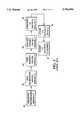
- FIG. 3is a functional block diagram of a laser imager system 44 incorporating a performance monitoring system 46, in accordance with the present invention.
- performance monitoring system 46can be implemented on-site with a laser imager 14.
- performance monitoring system 46preferably is configured to monitor the performance of one or more laser imagers 14 1 -14 N located remotely from the system.
- remote performance monitoring system 46as described herein, provides a means for implementing a remote performance monitoring method, in accordance with the present invention.
- the performance monitoring system 46automatically monitors one or more remotely located laser imagers 14 1 -14 N over a period of time to generate image quality control reports, eliminating the need for manual generation of such reports by a technician.
- the performance monitoring system 46also monitors modality usage, imaging media usage, and the occurrence of errors for each laser imager 14 1 -14 N , and automatically generates usage reports and error reports.
- system 46is capable of automatically sending the reports to users of laser imagers 14 1 -14 N , automatically initiating an order to send additional imaging media 22, and automatically initiating a request for dispatch of a service technician in response to an error condition.
- system 46is capable of generating the image quality control reports in conformance with standards of regulatory agencies or other organizations regulating usage of laser imagers 14 1 -14 N .
- the performance monitoring system 46in accordance with the present invention, can be realized by a software system configured to run on a UNIXTM computer operating system.
- the performance monitoring system 46preferably monitors one or more of laser imagers 14 1 -14 N distributed over a geographic region. For this reason, system 46 preferably is configured to communicate with laser imagers 14 1 -14 N by modem via public telephone lines 48 1 -48 N , as shown in FIG. 3.
- a memory 50 associated with system 46stores an access table and a polling table that guide system 46 in accessing laser imagers 14 1 -14 N .
- the polling tabledefines a schedule for periodically polling each of laser imagers 14 1 -14 N .
- the schedulemay require, for example, that system 46 poll each laser imager 14 1 -14 N on a daily basis.
- the access tablecontains the telephone numbers for each of the remotely located laser imagers 14 1 -14 N to be monitored by system 46.
- the performance monitoring system 46periodically polls each of laser imagers 14 1 -14 N to acquire data representative of one or more performance conditions.
- the system 46polls each laser imager 14 1 -14 N by continuously accessing the polling table to determine the next laser imager to be monitored, and then accessing the access table to associate a telephone number with the particular laser imager.
- the performance monitoring system 46dials up the telephone number of the appropriate laser imager 14 1 -14 by modem over telephone line 48 1 -48 N . Once communication is established with the laser imager 14 1 -14 N , system 46 interfaces with the processor 16 1 -16 N associated with the particular laser imager 14 1 -14 N . The system 46 uses processor 16 1 -16 N to acquire from memory 18 of laser imager 14 data representative of performance conditions. Specifically, system 46 obtains from memory 18 the image test data stored by the AIQC program executed by processor 16 1 -16 N . The image test data is representative of the results of the most recent image test procedure since the last polling period.
- system 46obtains from memory 18 the usage data logged by processor 16 1 -16 N concerning the amount of usage of laser imager 14 1 -14 N by different modalities 12 1 -12 N , and the amount of imaging media used for imaging operations requested by the modalities, since the last polling period. Finally, system 46 obtains from memory 18 the error data logged by processor 16 1 -16 N detailing any errors that may have occurred, as well as any "tally" data concerning the frequency of each type of error.
- the performance monitoring system 46stores all of the above data obtained from a particular laser imager 14 1 -14 N in a memory 50 for reference in generating a variety of reports representative of the data.
- system 46uses the data stored in memory 50 to generate one or more of: (1) an image quality control report representing various parameters indicative of imaging performance by the laser imager 14 1 -14 N , as indicated by block 52; (2) a combined modality/media usage report representing the usage of laser imager by different modalities 12 1 -12 N and the amount of imaging media 22 used by the laser imager, as indicated by block 54; and (3) an error report representing the occurrence of errors within the laser imager, as indicated by block 56.
- system 46also is configured to automatically send any of the above reports to a user associated with each laser imager 14 1 -14 N .
- the system 46may send the reports, for example, via facsimile transmission, electronic mail, or by postal service.
- system 46may send a request to processor 16 to visibly display the report on a display panel associated with laser imager 14 1 -14 N .
- system 46may send a request to processor 16 to print the report on a sheet of imaging media 22.
- system 46is configured to automatically initiate a request for a service technician, as indicated by block 60, in response to an error condition at a particular laser imager 14 1 -14 N sensed during generation of the error report. As indicated by block 62, system 46 further is configured to automatically initiate an order to send additional imaging media 22 to a particular laser imager 14 1 -14 N in response to a media usage condition sensed during generation of the usage report. Finally, as indicated by block 64, system 46 can be configured to allocate a monetary charge to each of the different modalities 12 1 -12 N proportional to the amount of usage of the particular laser imager 14 1 -14 N . As shown in FIG. 3, the monetary charge also can be automatically sent to a user of a particular laser imager 14 1 -14 N , thereby eliminating the need for modality accounting by hospital staff.
- system 46accesses the image test data stored in memory 50 for a particular laser imager 14 1 -14 N over a plurality of polling periods.
- the image test data stored in memory 50represents, for each image test procedure, the optical densities measured in the test image by densitometer 26, the corresponding exposure levels applied by scanning laser 20 in response to the calibration laser drive values to generate the optical densities, the temperature of developer 24 during the image test procedure, the type of imaging media 22 used to form the test image, and the date of the image test procedure.
- system 46calculates a set of parameters to be represented in the image quality control report.
- system 46may calculate a minimum optical density and a maximum optical density among the optical densities measured in the test image by densitometer 26.
- the system 46also calculates an optical density contrast index for the test image, and a "speed" index representative of the development response of imaging media 22 to the exposure levels applied by scanning laser 20.
- the optical density contrast indexis calculated by selecting a density measurement closest to, but not larger than, a density of 2.20, and subtracting from that density measurement the density measurement closest to, but not lower then, 0.45.
- the speed indexis calculated by selecting the density measurement closest to but not exceeding a density of 1.0, and adding to that density measurement the minimum optical density measurement, or "base+fog.”
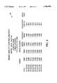
- FIG. 4is an example of a tabular component 66 of an image quality control report generated by performance monitoring system 46, in accordance with the present invention.
- system 46compiles them in a tabular form along with the date of the image test procedure, the pertinent developer temperature, and the media type, as may be represented by an emulsion number.
- the tabular component 66 of the image quality control reportincludes, from left to right, a date column indicating the dates (Oct. 1-9, 1994) of the particular image test procedures, the minimum measured optical density, a maximum measured optical density, the speed index, the contrast index, the developer temperature, and the media type.
- system 46also includes the date (Oct. 18, 1994) the report was generated by system 46, the location ("HOSPITAL NAME") of the particular laser imager 14 1 -14 N for which the report was generated, and the model and serial numbers of the particular laser imager.
- the tabular component 66 shown in FIG. 4is intended to be purely exemplary, with its form and content being subject to variation according to the needs of a user. It is noted, however, that system 46 can advantageously configure the form and content to conform to standards of a government regulatory agency or other organization regulating laser imagers 14 1 -14 N . In this manner, system 46 eliminates the manual effort previously required by hospital staff to generate an image quality control report.
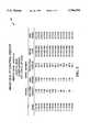
- FIG. 5is an example of an alternative tabular component 68 of an image quality control report generated by performance monitoring system 46, in accordance with the present invention.
- the example shown in FIG. 5substantially corresponds to that shown in FIG. 4, but incorporates a different set of parameters indicative of image quality.
- system 46configures tabular component 68 of the image quality control report to include, from left to right, the dates (Nov. 1-18, 1994) of the particular image test procedures, a measured mid-tone optical density, an AIQC speed, the developer temperature, and the media type.
- the measured mid-tone optical densityrepresents the actual measured optical density at a gradation expected to correspond to a mid-tone density value of 1.0.
- the mid-tone optical density measured for the test imageindicates the deviation from the ideal mid-tone density value, and thus provides a useful indicator of imaging quality.
- the AIQC speedis an alternative speed index that represents the log exposure value at which media 22 reaches a maximum optical density Dmax.
- the AIQC speedcan be readily calculated by system 46 by reference to the density measurements and corresponding exposure values included in the image test data obtained from laser imager 14.
- system 46includes in tabular component 68 of the image quality control report an indication of whether the AIQC program for the particular laser imager 14 1 -14 N was active or inactive at the time of the image test procedure. That is, system 46 determines whether the parameters deviate from corresponding reference values by more than a given tolerance.
- the reference valuescan be based on precalculated values stored in memory for particular types of film. Excessive deviation may be an indication that the AIQC program is unable to adequately compensate a particular laser imager 14 1 -14 N for system variations. This indication suggests to the system user that a correction is necessary, such as a change in the chemistry of developer 24.
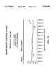
- FIG. 6is an example of a graphical component 70 of an image quality control report generated by remote performance monitoring system 46, in accordance with the present invention.
- the graphical component 70 of FIG. 6includes the date (Oct. 18, 1994) the report was generated by system 46, the location ("HOSPITAL NAME") of the particular laser imager 14 1 -14 N for which the report was generated, and the model and serial numbers of the particular laser imager.
- graphical component 70 of FIG. 6displays a set of graphs having an x-axis with the dates of particular image test procedures, and a y-axis with image test parameters such as minimum optical density, maximum optical density, optical contrast index, and speed index.
- image test parameterssuch as minimum optical density, maximum optical density, optical contrast index, and speed index.
- the individual chartsmay include reference lines indicating appropriate ranges for the particular parameters, based on reference values. Deviation from the ranges may indicate poor image quality.
- speed index chart 74includes a reference line 78 indicating a maximum speed index and a reference line 80 indicating a minimum speed index.
- Dmin chart 72includes a reference line 82 indicating a maximum Dmin value and a reference line 84 indicating a minimum Dmin value.
- contrast index chart 76includes a reference line 86 at a minimum contrast index and a reference line 88 at a contrast index of 1.0.
- FIG. 7is an example of an alternative graphical component of an image quality control report generated by remote performance monitoring system 46, in accordance with the present invention.
- the graphical component 90corresponds substantially to that shown in FIG. 6, but incorporates a different combination of charts.
- graphical component 90 of FIG. 7includes an AIQC speed chart 92 having a line 93 representative of the AIQC speed, which can be calculated as discussed above with respect to FIG. 5.
- the graphical component 90further includes an image mid-tone density chart 94 having a line 95 representative of the mid-tone density.
- the charts 92, 94graphically represent the AIQC speed and mid-tone density, respectively, shown in tabular component 68 of FIG. 5. Further, AIQC speed chart 92 of FIG.
- the image mid-tone density chart 94 of FIG. 7includes a dotted reference line 100 at the ideal mid-tone density value of 1.0.
- system 46accesses the usage data stored in memory 50 for a particular laser imager 14 1 -14 N over a plurality of polling periods.
- the usage data stored in memory 50represents the amount of usage of the particular laser imager 14 1 -14 N by each modality 12 1 -12.sub. N coupled to the laser imager over a plurality of polling periods, in terms of the number of imaging operations requested, and the amount of imaging media used by the laser imager for each modality.
- the system 46includes the modality usage data in the combined modality/media usage report.
- system 46may allocate a monetary charge to each of the different modalities 12 1 -12 N , and automatically send a report to a user of the particular laser imager 14 1 -14 N listing the charges.
- the monetary charge allocated to each of the modalities 12 1 -12 Nis proportional to the amount of usage of the particular laser imager 14 1 -14 N .
- the system 46also obtains the media usage data from memory 50 to determine the amount of imaging media 22 used for inclusion in the combined modality/media usage report. At the same time, system 46 accumulates a media usage value based on the amount of usage of imaging media 22 over a plurality of polling periods. Over consecutive polling periods, system 46 continuously compares the running media usage value to a threshold to determine whether the user of the particular laser imager 14 1 -14 N should be sent an additional amount of imaging media 22. If the media usage value exceeds the threshold, system 46 automatically initiates an order to send an additional amount of imaging media 22 to the user of the particular laser imager 14 1 -14 N . After determining modality and media usage, system 46 compiles them in a combined modality/media usage report.
- FIG. 8is an example of a combined modality/media usage report 102 generated by performance monitoring system 46, in accordance with the present invention.
- modality/media usage report 102includes the date (Oct. 18, 1994) the report was generated by system 46, the location ("HOSPITAL NAME") of the particular laser imager 14 1 -14 N for which the report was generated, and the model and serial numbers of the particular laser imager.
- the modality/media usage report 102further includes the particular modality 12 1 -12.sub. N ("GE CT,” etc.) requesting imaging operations, the number of imaging media 22 used by laser imager 14 1 -14 N for each modality, and the total number of imaging media used.
- the modality/media usage report 102could include additional information such as the time each imaging operation was requested to provide an indication of high imaging activity during certain times of the day.
- the modality/media usage report shown in FIG. 6is intended to be purely exemplary, with its form and content being subject to variation according to the needs of users.
- system 46accesses the error data stored in memory 50 for a particular laser imager 14 1 -14 N over a plurality of polling periods.
- the error data stored in memory 50details any errors that occurred within the particular laser imager 14 1 -14 N since the last polling period, providing the type of error, the time the error occurred, and the type of imaging media 22 being used when the error occurred.
- the errorsmay include incorrect operation of various electromechanical components within laser imager 14 1 -14 N , as sensed by processor 16 1 -16 N .
- the system 46includes in the error report all errors logged since the last polling period for analysis by a technician and/or a user of the laser imager 14 1 -14 N .
- the system 46also may include the frequency of each type of error for a particular laser imager 14 1 -14 N .
- the system 46compares the frequency of each type of error to a threshold. If the frequency of a particular error exceeds the threshold, system 46 recognizes a potential oncoming fault condition and automatically initiates an order for a service technician to visit the location associated with the particular laser imager 14 1 -14 N .
- system 46enables a degree of anticipation of conditions that could render the laser imager 14 1 -14 N unusable, and proactively initiates a service call without the need for a request by the user of the laser imager.
- system 46could be provided with a direct interface to a service management system (SMS), such as OpenUPTIMETM, to log a service call for assignment and scheduling by a dispatcher using the SMS.
- SMSservice management system
- FIG. 9is an example of an error report 104 generated by performance monitoring system 46, in accordance with the present invention.
- error report 104includes the date (Oct. 18, 1994) the report was generated by system 46, the location ("HOSPITAL NAME") of the particular laser imager 14 1 -14 N for which the report was generated, and the model and serial numbers of the particular laser imager.
- the error report 104further includes the type of imaging media 22 used when the error occurred, the type of error (“Error Descriptor”), the frequency (“Counts”) of errors of that type, the first occurrence of that type of error, and the last occurrence of that type of error.
- the "Error Descriptor” column of the error reportprovides an example of some of the different types of errors that may be logged for a laser imager 14 1 -14 N .
- the "Error Descriptor” columnincludes an FLMASL ("film almost slow") error, indicating that the AIQC speed has reached an almost unacceptable level, an EOFTMO ("end of film timeout error”) error, indicating an end-of-film has not been received for an image data file within an acceptable amount of time, and an RWDUNITTRIG (“rewind unit trigger error”) error, indicating a rewind unit associated with laser imager 14 has incurred a trigger error.
- FLMASLfilm almost slow
- EOFTMOend of film timeout error
- RWDUNITTRIGrewind unit trigger error
- the error report 104provides the user and/or technician with useful information for trouble-shooting problems that can affect image quality or disable the laser imager 14 1 -14 N .
- the form and content of the information included in the error report of FIG. 7is purely exemplary, however, and may supplemented or modified according to the individual needs of a user.
Landscapes
- Engineering & Computer Science (AREA)
- Health & Medical Sciences (AREA)
- Biomedical Technology (AREA)
- General Health & Medical Sciences (AREA)
- Multimedia (AREA)
- Signal Processing (AREA)
- Physics & Mathematics (AREA)
- General Engineering & Computer Science (AREA)
- General Physics & Mathematics (AREA)
- Theoretical Computer Science (AREA)
- Optics & Photonics (AREA)
- Microelectronics & Electronic Packaging (AREA)
- Computer Hardware Design (AREA)
- Quality & Reliability (AREA)
- Apparatus For Radiation Diagnosis (AREA)
- Accessory Devices And Overall Control Thereof (AREA)
- Medical Treatment And Welfare Office Work (AREA)
- Measuring And Recording Apparatus For Diagnosis (AREA)
- Image Processing (AREA)
Abstract
Description
Claims (74)
Priority Applications (6)
| Application Number | Priority Date | Filing Date | Title |
|---|---|---|---|
| US08/344,146US5786994A (en) | 1994-11-23 | 1994-11-23 | Performance monitoring system and method for a laser medical imager |
| AU40008/95AAU4000895A (en) | 1994-11-23 | 1995-10-10 | Performance monitoring system and method for a laser imager |
| PCT/US1995/013188WO1996016506A1 (en) | 1994-11-23 | 1995-10-10 | Performance monitoring system and method for a laser imager |
| EP95938744AEP0795247A1 (en) | 1994-11-23 | 1995-10-10 | Performance monitoring system and method for a laser imager |
| CA002204114ACA2204114A1 (en) | 1994-11-23 | 1995-10-10 | Performance monitoring system and method for a laser imager |
| JP8516834AJPH10510061A (en) | 1994-11-23 | 1995-10-10 | Operation monitoring system and method for laser image forming apparatus |
Applications Claiming Priority (1)
| Application Number | Priority Date | Filing Date | Title |
|---|---|---|---|
| US08/344,146US5786994A (en) | 1994-11-23 | 1994-11-23 | Performance monitoring system and method for a laser medical imager |
Publications (1)
| Publication Number | Publication Date |
|---|---|
| US5786994Atrue US5786994A (en) | 1998-07-28 |
Family
ID=23349255
Family Applications (1)
| Application Number | Title | Priority Date | Filing Date |
|---|---|---|---|
| US08/344,146Expired - LifetimeUS5786994A (en) | 1994-11-23 | 1994-11-23 | Performance monitoring system and method for a laser medical imager |
Country Status (6)
| Country | Link |
|---|---|
| US (1) | US5786994A (en) |
| EP (1) | EP0795247A1 (en) |
| JP (1) | JPH10510061A (en) |
| AU (1) | AU4000895A (en) |
| CA (1) | CA2204114A1 (en) |
| WO (1) | WO1996016506A1 (en) |
Cited By (58)
| Publication number | Priority date | Publication date | Assignee | Title |
|---|---|---|---|---|
| US5873009A (en)* | 1995-11-06 | 1999-02-16 | Mita Industrial Co., Ltd. | Equipment management system that issues a warning when the lifetime of a component has been exceeded and disables the warning when such a warning is to be generated for a different component |
| US6020909A (en)* | 1997-11-26 | 2000-02-01 | Eastman Kodak Company | Maintenance of calibration of a photothermographic laser printer and processor system |
| EP0991008A2 (en) | 1998-09-30 | 2000-04-05 | General Electric Company | Method and apparatus for capturing and automatically transferring an x-ray image to a remote location |
| US6212256B1 (en)* | 1998-11-25 | 2001-04-03 | Ge Medical Global Technology Company, Llc | X-ray tube replacement management system |
| US20020008883A1 (en)* | 2000-05-02 | 2002-01-24 | Ricoh Company, Ltd. | Method and apparatus for data communications capable of automatically sending a maintenance request |
| EP1109395A3 (en)* | 1999-12-16 | 2002-04-10 | Xerox Corporation | Systems and methods for automated image quality based diagnostics and remediation of document processing systems |
| US20020049623A1 (en)* | 2000-07-20 | 2002-04-25 | Martin June Dianne | System and method for implementing an image-based document handling and delivery system |
| US6381557B1 (en)* | 1998-11-25 | 2002-04-30 | Ge Medical Systems Global Technology Company, Llc | Medical imaging system service evaluation method and apparatus |
| FR2816079A1 (en)* | 2000-10-31 | 2002-05-03 | Ge Medical Tech Serv | Method for monitoring connections to remote installations, comprises connection of central station to remote installations, storing event in database and reporting incorrect connections percentage |
| US6389156B1 (en)* | 1997-10-09 | 2002-05-14 | Konica Corporation | Method and apparatus for reading radiographic images |
| US20030200349A1 (en)* | 2002-04-17 | 2003-10-23 | Hansen James R. | XML scripting of soap commands |
| US20030204372A1 (en)* | 2002-04-29 | 2003-10-30 | The Boeing Company | Monitoring and preventing failure of an automated theater system |
| US20040061884A1 (en)* | 2002-09-30 | 2004-04-01 | Fuji Photo Film Co., Ltd. | Printer, method for controlling quality of printing density in printer and system therefor |
| US6735641B1 (en)* | 1998-10-28 | 2004-05-11 | Fuji Xerox Co., Ltd. | Peripheral equipment management device, a peripheral device connected to a peripheral management device, and a method of the same of executing a process in accordance with a process schedule generated on the basis of information sent from a device and transmitting a result to a monitoring device |
| US20040122705A1 (en)* | 2002-12-18 | 2004-06-24 | Sabol John M. | Multilevel integrated medical knowledge base system and method |
| US20040122719A1 (en)* | 2002-12-18 | 2004-06-24 | Sabol John M. | Medical resource processing system and method utilizing multiple resource type data |
| US20040122703A1 (en)* | 2002-12-19 | 2004-06-24 | Walker Matthew J. | Medical data operating model development system and method |
| US20040122704A1 (en)* | 2002-12-18 | 2004-06-24 | Sabol John M. | Integrated medical knowledge base interface system and method |
| US20040122702A1 (en)* | 2002-12-18 | 2004-06-24 | Sabol John M. | Medical data processing system and method |
| US20040122707A1 (en)* | 2002-12-18 | 2004-06-24 | Sabol John M. | Patient-driven medical data processing system and method |
| US20040122706A1 (en)* | 2002-12-18 | 2004-06-24 | Walker Matthew J. | Patient data acquisition system and method |
| US20040122787A1 (en)* | 2002-12-18 | 2004-06-24 | Avinash Gopal B. | Enhanced computer-assisted medical data processing system and method |
| US20040122709A1 (en)* | 2002-12-18 | 2004-06-24 | Avinash Gopal B. | Medical procedure prioritization system and method utilizing integrated knowledge base |
| US20040122708A1 (en)* | 2002-12-18 | 2004-06-24 | Avinash Gopal B. | Medical data analysis method and apparatus incorporating in vitro test data |
| US20040122790A1 (en)* | 2002-12-18 | 2004-06-24 | Walker Matthew J. | Computer-assisted data processing system and method incorporating automated learning |
| US20040138920A1 (en)* | 2002-10-18 | 2004-07-15 | Kabushiki Kaisha Toshiba | Medical equipment management apparatus which predicts future status of medical equipment |
| EP1079593A3 (en)* | 1999-08-27 | 2004-08-18 | E.I. Dupont De Nemours And Company | Method and apparatus for remote printing |
| US20040177124A1 (en)* | 2000-07-28 | 2004-09-09 | Hansen James R. | Reporting the state of an apparatus to a remote computer |
| EP1160716A3 (en)* | 2000-06-01 | 2004-12-01 | General Electric Company | System for automatically acquiring exam data from medical imaging devices and gererating reports on radiology department operations |
| US20040260790A1 (en)* | 2000-12-21 | 2004-12-23 | Ge Medical System Global Technology Company, Llc | Method and apparatus for remote or collaborative control of an imaging system |
| US20050103354A1 (en)* | 2003-09-24 | 2005-05-19 | Kabushiki Kaisha Toshiba | Method of determining maintenance service in accordance with medical equipment condition |
| US6934590B2 (en)* | 1999-03-25 | 2005-08-23 | Fuji Photo Film Co., Ltd. | Quality control system for medical diagnostic apparatus |
| US20050246120A1 (en)* | 2002-06-07 | 2005-11-03 | Peter Hein | Computer tomography unit with a data recording system |
| US6963907B1 (en)* | 2000-03-27 | 2005-11-08 | Cardiobeat.Com | Internet device operation for medical testing |
| US20050256743A1 (en)* | 2004-05-11 | 2005-11-17 | Dale Richard B | Medical imaging-quality assessment and improvement system (QAISys) |
| US20060106507A1 (en)* | 2004-11-12 | 2006-05-18 | The Boeing Company | Optical laser guidance system apparatus and method |
| US20060136417A1 (en)* | 2004-12-17 | 2006-06-22 | General Electric Company | Method and system for search, analysis and display of structured data |
| US20060136259A1 (en)* | 2004-12-17 | 2006-06-22 | General Electric Company | Multi-dimensional analysis of medical data |
| US20060195564A1 (en)* | 1998-11-25 | 2006-08-31 | Accardi Kenneth L | Medical diagnostic system service method and apparatus |
| US20060212317A1 (en)* | 2005-01-19 | 2006-09-21 | Hahn Jerad J | Mammography operational management system and method |
| US7117239B1 (en) | 2000-07-28 | 2006-10-03 | Axeda Corporation | Reporting the state of an apparatus to a remote computer |
| US7149792B1 (en) | 2000-11-20 | 2006-12-12 | Axeda Corporation | Device registration mechanism |
| US7185014B1 (en) | 2000-09-22 | 2007-02-27 | Axeda Corporation | Retrieving data from a server |
| US20070078873A1 (en)* | 2005-09-30 | 2007-04-05 | Avinash Gopal B | Computer assisted domain specific entity mapping method and system |
| US20070124112A1 (en)* | 2005-11-25 | 2007-05-31 | Bernhard Weyermann | Method and computer program for determining performance of a computer system |
| US7298876B1 (en)* | 2002-11-04 | 2007-11-20 | R2 Technology, Inc. | Method and apparatus for quality assurance and quality control in radiological equipment using automatic analysis tools |
| US7383358B1 (en)* | 1999-12-29 | 2008-06-03 | Ge Medical Technology Services, Inc. | System and method for remote servicing of in-field product |
| US20080158603A1 (en)* | 2006-12-27 | 2008-07-03 | Brother Kogyo Kabushiki Kaisha | Information Processing Device |
| US20090313302A1 (en)* | 2008-06-13 | 2009-12-17 | Sony Ericsson Mobile Communications Ab | Automatic song selection |
| CN1725242B (en)* | 2002-09-10 | 2010-10-13 | 国际商业机器公司 | Method for solving transferred error in automatic material processing system |
| US7966418B2 (en) | 2003-02-21 | 2011-06-21 | Axeda Corporation | Establishing a virtual tunnel between two computer programs |
| US8065397B2 (en) | 2006-12-26 | 2011-11-22 | Axeda Acquisition Corporation | Managing configurations of distributed devices |
| US8108543B2 (en) | 2000-09-22 | 2012-01-31 | Axeda Corporation | Retrieving data from a server |
| US8370479B2 (en) | 2006-10-03 | 2013-02-05 | Axeda Acquisition Corporation | System and method for dynamically grouping devices based on present device conditions |
| US8406119B2 (en) | 2001-12-20 | 2013-03-26 | Axeda Acquisition Corporation | Adaptive device-initiated polling |
| US8478861B2 (en) | 2007-07-06 | 2013-07-02 | Axeda Acquisition Corp. | Managing distributed devices with limited connectivity |
| US9753676B1 (en)* | 2016-03-07 | 2017-09-05 | Kyocera Document Solutions Inc. | System and method for managing printing devices using activity scores |
| US20190156942A1 (en)* | 2016-07-15 | 2019-05-23 | Koninklijke Philips N.V. | Apparatus for assessing medical device quality |
Families Citing this family (9)
| Publication number | Priority date | Publication date | Assignee | Title |
|---|---|---|---|---|
| JP3408119B2 (en)* | 1996-08-23 | 2003-05-19 | キヤノン株式会社 | Image processing apparatus and method, and recording medium |
| US6031621A (en)* | 1996-11-05 | 2000-02-29 | Hewlett-Packard Company | Information collection system |
| JPH1115216A (en)* | 1997-06-26 | 1999-01-22 | Canon Inc | Image processing apparatus and control method thereof, and recording medium |
| JPH11103364A (en) | 1997-09-26 | 1999-04-13 | Ricoh Co Ltd | Facsimile machine |
| JP2003011419A (en)* | 2001-06-29 | 2003-01-15 | Dainippon Screen Mfg Co Ltd | Image recorder |
| JP4585161B2 (en)* | 2002-01-24 | 2010-11-24 | 株式会社東芝 | Inspection reservation system |
| JP2004205554A (en)* | 2002-12-20 | 2004-07-22 | Konica Minolta Holdings Inc | Image processing device, image processing method and program |
| US7172212B2 (en) | 2004-09-22 | 2007-02-06 | Honda Motor Co., Ltd. | Vehicle occupant protection device |
| US7407182B2 (en) | 2004-09-22 | 2008-08-05 | Honda Motor Co., Ltd. | Vehicle occupant protection device |
Citations (30)
| Publication number | Priority date | Publication date | Assignee | Title |
|---|---|---|---|---|
| US4213462A (en)* | 1977-08-25 | 1980-07-22 | Nobuhiro Sato | Optical assembly for detecting an abnormality of an organ or tissue and method |
| US4315318A (en)* | 1978-12-26 | 1982-02-09 | Fuji Photo Film Co., Ltd. | Method and apparatus for processing a radiation image |
| US4583834A (en)* | 1977-09-16 | 1986-04-22 | Ricoh Company, Ltd. | Copying apparatus |
| EP0342910A2 (en)* | 1988-05-17 | 1989-11-23 | Monitel Products Corporation | Photocopy monitoring system and method for monitoring copiers |
| US4958283A (en)* | 1987-07-08 | 1990-09-18 | Kabushiki Kaisha Toshiba | Method and system for storing and communicating medical image data |
| US4965672A (en)* | 1987-05-11 | 1990-10-23 | The Mead Corporation | Method and apparatus for halftone imaging |
| US4993025A (en)* | 1989-11-21 | 1991-02-12 | Picker International, Inc. | High efficiency image data transfer network |
| US5049747A (en)* | 1990-03-06 | 1991-09-17 | Fuji Photo Film Co., Ltd. | Radiation image recording and reproducing system |
| WO1992003789A1 (en)* | 1990-08-14 | 1992-03-05 | Joseph Weinberger | Improvement in system for automatically monitoring copiers from a remote location |
| US5099848A (en)* | 1990-11-02 | 1992-03-31 | University Of Rochester | Method and apparatus for breast imaging and tumor detection using modal vibration analysis |
| US5111044A (en)* | 1990-04-10 | 1992-05-05 | Fuji Photo Film Co., Ltd. | Medical image reproducing system |
| US5117119A (en)* | 1991-03-13 | 1992-05-26 | Minnesota Mining And Manufacturing Company | Auto-ranging film densitometer |
| US5124789A (en)* | 1988-09-07 | 1992-06-23 | Olympus Optical Co., Ltd. | Medical image filing apparatus and filing method for registering images from a plurality of image output devices in a single examination |
| US5140518A (en)* | 1988-10-28 | 1992-08-18 | Kabushiki Kaisha Toshiba | Method and apparatus for processing data in medical information communication system |
| US5172419A (en)* | 1991-03-05 | 1992-12-15 | Lumisys, Inc. | Medical image processing system |
| US5194966A (en)* | 1990-11-20 | 1993-03-16 | Educational Testing Service | Optical scanner threshold setting method and sheet |
| US5229585A (en)* | 1991-02-19 | 1993-07-20 | Minnesota Mining And Manufacturing Company | Film cartridge bar code scanner and controller for a digital imaging system |
| US5272625A (en)* | 1990-05-17 | 1993-12-21 | Kabushiki Kaisha Toshiba | Medical image data managing system |
| US5282127A (en)* | 1989-11-20 | 1994-01-25 | Sanyo Electric Co., Ltd. | Centralized control system for terminal device |
| US5303005A (en)* | 1990-01-31 | 1994-04-12 | Minolta Camera Kabushiki Kaisha | Image forming apparatus with improved maintenance control |
| US5305055A (en)* | 1992-12-16 | 1994-04-19 | Xerox Corporation | Automatic call to selected remote operators in response to predetermined machine conditions |
| US5305199A (en)* | 1992-10-28 | 1994-04-19 | Xerox Corporation | Consumable supplies monitoring/ordering system for reprographic equipment |
| EP0599261A1 (en)* | 1992-11-25 | 1994-06-01 | Minnesota Mining And Manufacturing Company | Multi-user digital laser imaging system |
| US5319543A (en)* | 1992-06-19 | 1994-06-07 | First Data Health Services Corporation | Workflow server for medical records imaging and tracking system |
| US5321520A (en)* | 1992-07-20 | 1994-06-14 | Automated Medical Access Corporation | Automated high definition/resolution image storage, retrieval and transmission system |
| US5343276A (en)* | 1992-05-27 | 1994-08-30 | Mita Industrial Co., Ltd. | Management system of image forming apparatuses |
| US5347346A (en)* | 1989-12-25 | 1994-09-13 | Minolta Camera Kabushiki Kaisha | Image forming apparatus with improved efficiency of maintenance control |
| US5528492A (en)* | 1991-09-06 | 1996-06-18 | Kabushiki Kaisha Toshiba | Method of managing medical diagnostic data with reference relationship |
| US5581460A (en)* | 1990-11-06 | 1996-12-03 | Kabushiki Kaisha Toshiba | Medical diagnostic report forming apparatus capable of attaching image data on report |
| US5598185A (en)* | 1994-06-10 | 1997-01-28 | Integrated Image Solutions | System for analyzing medical images having a particular color and intensity look-up table |
- 1994
- 1994-11-23USUS08/344,146patent/US5786994A/ennot_activeExpired - Lifetime
- 1995
- 1995-10-10EPEP95938744Apatent/EP0795247A1/ennot_activeWithdrawn
- 1995-10-10WOPCT/US1995/013188patent/WO1996016506A1/ennot_activeApplication Discontinuation
- 1995-10-10AUAU40008/95Apatent/AU4000895A/ennot_activeAbandoned
- 1995-10-10JPJP8516834Apatent/JPH10510061A/enactivePending
- 1995-10-10CACA002204114Apatent/CA2204114A1/ennot_activeAbandoned
Patent Citations (30)
| Publication number | Priority date | Publication date | Assignee | Title |
|---|---|---|---|---|
| US4213462A (en)* | 1977-08-25 | 1980-07-22 | Nobuhiro Sato | Optical assembly for detecting an abnormality of an organ or tissue and method |
| US4583834A (en)* | 1977-09-16 | 1986-04-22 | Ricoh Company, Ltd. | Copying apparatus |
| US4315318A (en)* | 1978-12-26 | 1982-02-09 | Fuji Photo Film Co., Ltd. | Method and apparatus for processing a radiation image |
| US4965672A (en)* | 1987-05-11 | 1990-10-23 | The Mead Corporation | Method and apparatus for halftone imaging |
| US4958283A (en)* | 1987-07-08 | 1990-09-18 | Kabushiki Kaisha Toshiba | Method and system for storing and communicating medical image data |
| EP0342910A2 (en)* | 1988-05-17 | 1989-11-23 | Monitel Products Corporation | Photocopy monitoring system and method for monitoring copiers |
| US5124789A (en)* | 1988-09-07 | 1992-06-23 | Olympus Optical Co., Ltd. | Medical image filing apparatus and filing method for registering images from a plurality of image output devices in a single examination |
| US5140518A (en)* | 1988-10-28 | 1992-08-18 | Kabushiki Kaisha Toshiba | Method and apparatus for processing data in medical information communication system |
| US5282127A (en)* | 1989-11-20 | 1994-01-25 | Sanyo Electric Co., Ltd. | Centralized control system for terminal device |
| US4993025A (en)* | 1989-11-21 | 1991-02-12 | Picker International, Inc. | High efficiency image data transfer network |
| US5347346A (en)* | 1989-12-25 | 1994-09-13 | Minolta Camera Kabushiki Kaisha | Image forming apparatus with improved efficiency of maintenance control |
| US5303005A (en)* | 1990-01-31 | 1994-04-12 | Minolta Camera Kabushiki Kaisha | Image forming apparatus with improved maintenance control |
| US5049747A (en)* | 1990-03-06 | 1991-09-17 | Fuji Photo Film Co., Ltd. | Radiation image recording and reproducing system |
| US5111044A (en)* | 1990-04-10 | 1992-05-05 | Fuji Photo Film Co., Ltd. | Medical image reproducing system |
| US5272625A (en)* | 1990-05-17 | 1993-12-21 | Kabushiki Kaisha Toshiba | Medical image data managing system |
| WO1992003789A1 (en)* | 1990-08-14 | 1992-03-05 | Joseph Weinberger | Improvement in system for automatically monitoring copiers from a remote location |
| US5099848A (en)* | 1990-11-02 | 1992-03-31 | University Of Rochester | Method and apparatus for breast imaging and tumor detection using modal vibration analysis |
| US5581460A (en)* | 1990-11-06 | 1996-12-03 | Kabushiki Kaisha Toshiba | Medical diagnostic report forming apparatus capable of attaching image data on report |
| US5194966A (en)* | 1990-11-20 | 1993-03-16 | Educational Testing Service | Optical scanner threshold setting method and sheet |
| US5229585A (en)* | 1991-02-19 | 1993-07-20 | Minnesota Mining And Manufacturing Company | Film cartridge bar code scanner and controller for a digital imaging system |
| US5172419A (en)* | 1991-03-05 | 1992-12-15 | Lumisys, Inc. | Medical image processing system |
| US5117119A (en)* | 1991-03-13 | 1992-05-26 | Minnesota Mining And Manufacturing Company | Auto-ranging film densitometer |
| US5528492A (en)* | 1991-09-06 | 1996-06-18 | Kabushiki Kaisha Toshiba | Method of managing medical diagnostic data with reference relationship |
| US5343276A (en)* | 1992-05-27 | 1994-08-30 | Mita Industrial Co., Ltd. | Management system of image forming apparatuses |
| US5319543A (en)* | 1992-06-19 | 1994-06-07 | First Data Health Services Corporation | Workflow server for medical records imaging and tracking system |
| US5321520A (en)* | 1992-07-20 | 1994-06-14 | Automated Medical Access Corporation | Automated high definition/resolution image storage, retrieval and transmission system |
| US5305199A (en)* | 1992-10-28 | 1994-04-19 | Xerox Corporation | Consumable supplies monitoring/ordering system for reprographic equipment |
| EP0599261A1 (en)* | 1992-11-25 | 1994-06-01 | Minnesota Mining And Manufacturing Company | Multi-user digital laser imaging system |
| US5305055A (en)* | 1992-12-16 | 1994-04-19 | Xerox Corporation | Automatic call to selected remote operators in response to predetermined machine conditions |
| US5598185A (en)* | 1994-06-10 | 1997-01-28 | Integrated Image Solutions | System for analyzing medical images having a particular color and intensity look-up table |
Cited By (101)
| Publication number | Priority date | Publication date | Assignee | Title |
|---|---|---|---|---|
| US5873009A (en)* | 1995-11-06 | 1999-02-16 | Mita Industrial Co., Ltd. | Equipment management system that issues a warning when the lifetime of a component has been exceeded and disables the warning when such a warning is to be generated for a different component |
| US6389156B1 (en)* | 1997-10-09 | 2002-05-14 | Konica Corporation | Method and apparatus for reading radiographic images |
| US6020909A (en)* | 1997-11-26 | 2000-02-01 | Eastman Kodak Company | Maintenance of calibration of a photothermographic laser printer and processor system |
| EP0991008A2 (en) | 1998-09-30 | 2000-04-05 | General Electric Company | Method and apparatus for capturing and automatically transferring an x-ray image to a remote location |
| EP0991008A3 (en)* | 1998-09-30 | 2004-04-14 | General Electric Company | Method and apparatus for capturing and automatically transferring an x-ray image to a remote location |
| US6735641B1 (en)* | 1998-10-28 | 2004-05-11 | Fuji Xerox Co., Ltd. | Peripheral equipment management device, a peripheral device connected to a peripheral management device, and a method of the same of executing a process in accordance with a process schedule generated on the basis of information sent from a device and transmitting a result to a monitoring device |
| US7127499B1 (en)* | 1998-11-25 | 2006-10-24 | General Electric Company | Medical diagnostic system service method and apparatus |
| US6212256B1 (en)* | 1998-11-25 | 2001-04-03 | Ge Medical Global Technology Company, Llc | X-ray tube replacement management system |
| US6381557B1 (en)* | 1998-11-25 | 2002-04-30 | Ge Medical Systems Global Technology Company, Llc | Medical imaging system service evaluation method and apparatus |
| US20060195564A1 (en)* | 1998-11-25 | 2006-08-31 | Accardi Kenneth L | Medical diagnostic system service method and apparatus |
| US6934590B2 (en)* | 1999-03-25 | 2005-08-23 | Fuji Photo Film Co., Ltd. | Quality control system for medical diagnostic apparatus |
| EP1079593A3 (en)* | 1999-08-27 | 2004-08-18 | E.I. Dupont De Nemours And Company | Method and apparatus for remote printing |
| US7126705B1 (en) | 1999-08-27 | 2006-10-24 | E. I. Du Pont De Nemours And Company | Method and apparatus for remote printing |
| EP1109395A3 (en)* | 1999-12-16 | 2002-04-10 | Xerox Corporation | Systems and methods for automated image quality based diagnostics and remediation of document processing systems |
| US6665425B1 (en) | 1999-12-16 | 2003-12-16 | Xerox Corporation | Systems and methods for automated image quality based diagnostics and remediation of document processing systems |
| US7383358B1 (en)* | 1999-12-29 | 2008-06-03 | Ge Medical Technology Services, Inc. | System and method for remote servicing of in-field product |
| US6963907B1 (en)* | 2000-03-27 | 2005-11-08 | Cardiobeat.Com | Internet device operation for medical testing |
| US20020008883A1 (en)* | 2000-05-02 | 2002-01-24 | Ricoh Company, Ltd. | Method and apparatus for data communications capable of automatically sending a maintenance request |
| US7584273B2 (en)* | 2000-05-02 | 2009-09-01 | Ricoh Company, Ltd. | Method and apparatus for data communications capable of automatically sending a maintenance request |
| US20060004870A1 (en)* | 2000-06-01 | 2006-01-05 | Pomeroy Bruce D | System for automatically acquiring exam data from medical imaging devices and generating reports on radiology department operations |
| EP1160716A3 (en)* | 2000-06-01 | 2004-12-01 | General Electric Company | System for automatically acquiring exam data from medical imaging devices and gererating reports on radiology department operations |
| US20020049623A1 (en)* | 2000-07-20 | 2002-04-25 | Martin June Dianne | System and method for implementing an image-based document handling and delivery system |
| US8055758B2 (en) | 2000-07-28 | 2011-11-08 | Axeda Corporation | Reporting the state of an apparatus to a remote computer |
| US8898294B2 (en) | 2000-07-28 | 2014-11-25 | Axeda Corporation | Reporting the state of an apparatus to a remote computer |
| US20040177124A1 (en)* | 2000-07-28 | 2004-09-09 | Hansen James R. | Reporting the state of an apparatus to a remote computer |
| US7117239B1 (en) | 2000-07-28 | 2006-10-03 | Axeda Corporation | Reporting the state of an apparatus to a remote computer |
| US10069937B2 (en) | 2000-09-22 | 2018-09-04 | Ptc Inc. | Retrieving data from a server |
| US8762497B2 (en) | 2000-09-22 | 2014-06-24 | Axeda Corporation | Retrieving data from a server |
| US7185014B1 (en) | 2000-09-22 | 2007-02-27 | Axeda Corporation | Retrieving data from a server |
| US7937370B2 (en) | 2000-09-22 | 2011-05-03 | Axeda Corporation | Retrieving data from a server |
| US8108543B2 (en) | 2000-09-22 | 2012-01-31 | Axeda Corporation | Retrieving data from a server |
| FR2816079A1 (en)* | 2000-10-31 | 2002-05-03 | Ge Medical Tech Serv | Method for monitoring connections to remote installations, comprises connection of central station to remote installations, storing event in database and reporting incorrect connections percentage |
| US7149792B1 (en) | 2000-11-20 | 2006-12-12 | Axeda Corporation | Device registration mechanism |
| US20040260790A1 (en)* | 2000-12-21 | 2004-12-23 | Ge Medical System Global Technology Company, Llc | Method and apparatus for remote or collaborative control of an imaging system |
| US9170902B2 (en) | 2001-12-20 | 2015-10-27 | Ptc Inc. | Adaptive device-initiated polling |
| US8406119B2 (en) | 2001-12-20 | 2013-03-26 | Axeda Acquisition Corporation | Adaptive device-initiated polling |
| US9674067B2 (en) | 2001-12-20 | 2017-06-06 | PTC, Inc. | Adaptive device-initiated polling |
| US8752074B2 (en) | 2002-04-17 | 2014-06-10 | Axeda Corporation | Scripting of soap commands |
| US9591065B2 (en) | 2002-04-17 | 2017-03-07 | Ptc Inc. | Scripting of SOAP commands |
| US10708346B2 (en) | 2002-04-17 | 2020-07-07 | Ptc Inc. | Scripting of soap commands |
| US8060886B2 (en) | 2002-04-17 | 2011-11-15 | Axeda Corporation | XML scripting of SOAP commands |
| US20030200349A1 (en)* | 2002-04-17 | 2003-10-23 | Hansen James R. | XML scripting of soap commands |
| US7178149B2 (en) | 2002-04-17 | 2007-02-13 | Axeda Corporation | XML scripting of soap commands |
| US6862554B2 (en)* | 2002-04-29 | 2005-03-01 | The Boeing Company | Monitoring and preventing failure of an automated theater system |
| US20030204372A1 (en)* | 2002-04-29 | 2003-10-30 | The Boeing Company | Monitoring and preventing failure of an automated theater system |
| US7191093B2 (en)* | 2002-06-07 | 2007-03-13 | Siemens Aktiengesellschaft | Computer tomography unit with a data recording system |
| US20050246120A1 (en)* | 2002-06-07 | 2005-11-03 | Peter Hein | Computer tomography unit with a data recording system |
| CN1725242B (en)* | 2002-09-10 | 2010-10-13 | 国际商业机器公司 | Method for solving transferred error in automatic material processing system |
| US20040061884A1 (en)* | 2002-09-30 | 2004-04-01 | Fuji Photo Film Co., Ltd. | Printer, method for controlling quality of printing density in printer and system therefor |
| US20040138920A1 (en)* | 2002-10-18 | 2004-07-15 | Kabushiki Kaisha Toshiba | Medical equipment management apparatus which predicts future status of medical equipment |
| CN100518647C (en)* | 2002-10-18 | 2009-07-29 | 株式会社东芝 | Medical equipment managing apparatus for predicting its future state |
| US8489408B2 (en)* | 2002-10-18 | 2013-07-16 | Kabushiki Kaisha Toshiba | Medical equipment management apparatus which predicts future status of medical equipment |
| US7298876B1 (en)* | 2002-11-04 | 2007-11-20 | R2 Technology, Inc. | Method and apparatus for quality assurance and quality control in radiological equipment using automatic analysis tools |
| US20040122708A1 (en)* | 2002-12-18 | 2004-06-24 | Avinash Gopal B. | Medical data analysis method and apparatus incorporating in vitro test data |
| US20040122702A1 (en)* | 2002-12-18 | 2004-06-24 | Sabol John M. | Medical data processing system and method |
| US20040122705A1 (en)* | 2002-12-18 | 2004-06-24 | Sabol John M. | Multilevel integrated medical knowledge base system and method |
| US7490085B2 (en) | 2002-12-18 | 2009-02-10 | Ge Medical Systems Global Technology Company, Llc | Computer-assisted data processing system and method incorporating automated learning |
| US20040122787A1 (en)* | 2002-12-18 | 2004-06-24 | Avinash Gopal B. | Enhanced computer-assisted medical data processing system and method |
| US20040122790A1 (en)* | 2002-12-18 | 2004-06-24 | Walker Matthew J. | Computer-assisted data processing system and method incorporating automated learning |
| US20040122709A1 (en)* | 2002-12-18 | 2004-06-24 | Avinash Gopal B. | Medical procedure prioritization system and method utilizing integrated knowledge base |
| US20040122719A1 (en)* | 2002-12-18 | 2004-06-24 | Sabol John M. | Medical resource processing system and method utilizing multiple resource type data |
| US20040122707A1 (en)* | 2002-12-18 | 2004-06-24 | Sabol John M. | Patient-driven medical data processing system and method |
| US20040122704A1 (en)* | 2002-12-18 | 2004-06-24 | Sabol John M. | Integrated medical knowledge base interface system and method |
| US20040122706A1 (en)* | 2002-12-18 | 2004-06-24 | Walker Matthew J. | Patient data acquisition system and method |
| US20040122703A1 (en)* | 2002-12-19 | 2004-06-24 | Walker Matthew J. | Medical data operating model development system and method |
| US7966418B2 (en) | 2003-02-21 | 2011-06-21 | Axeda Corporation | Establishing a virtual tunnel between two computer programs |
| US10069939B2 (en) | 2003-02-21 | 2018-09-04 | Ptc Inc. | Establishing a virtual tunnel between two computers |
| US9002980B2 (en) | 2003-02-21 | 2015-04-07 | Axeda Corporation | Establishing a virtual tunnel between two computer programs |
| US8291039B2 (en) | 2003-02-21 | 2012-10-16 | Axeda Corporation | Establishing a virtual tunnel between two computer programs |
| US7970623B2 (en)* | 2003-09-24 | 2011-06-28 | Kabushiki Kaisha Toshiba | Method of determining maintenance service in accordance with medical equipment condition |
| US20050103354A1 (en)* | 2003-09-24 | 2005-05-19 | Kabushiki Kaisha Toshiba | Method of determining maintenance service in accordance with medical equipment condition |
| US7680308B2 (en) | 2004-05-11 | 2010-03-16 | Dale Richard B | Medical imaging-quality assessment and improvement system (QAISys) |
| US20050256743A1 (en)* | 2004-05-11 | 2005-11-17 | Dale Richard B | Medical imaging-quality assessment and improvement system (QAISys) |
| US20090198401A1 (en)* | 2004-11-12 | 2009-08-06 | The Boeing Company | Optical laser guidance system and method |
| US20060106507A1 (en)* | 2004-11-12 | 2006-05-18 | The Boeing Company | Optical laser guidance system apparatus and method |
| US7899618B2 (en) | 2004-11-12 | 2011-03-01 | The Boeing Company | Optical laser guidance system and method |
| US7536242B2 (en)* | 2004-11-12 | 2009-05-19 | The Boeing Company | Optical laser guidance system apparatus and method |
| US20060136417A1 (en)* | 2004-12-17 | 2006-06-22 | General Electric Company | Method and system for search, analysis and display of structured data |
| US20060136259A1 (en)* | 2004-12-17 | 2006-06-22 | General Electric Company | Multi-dimensional analysis of medical data |
| US8428969B2 (en)* | 2005-01-19 | 2013-04-23 | Atirix Medical Systems, Inc. | System and method for tracking medical imaging quality |
| US8478610B2 (en) | 2005-01-19 | 2013-07-02 | Atirix Medical Systems | Medical imaging device quality control system and method |
| US20060212317A1 (en)* | 2005-01-19 | 2006-09-21 | Hahn Jerad J | Mammography operational management system and method |
| US20070078873A1 (en)* | 2005-09-30 | 2007-04-05 | Avinash Gopal B | Computer assisted domain specific entity mapping method and system |
| US20070124112A1 (en)* | 2005-11-25 | 2007-05-31 | Bernhard Weyermann | Method and computer program for determining performance of a computer system |
| US9491071B2 (en) | 2006-10-03 | 2016-11-08 | Ptc Inc. | System and method for dynamically grouping devices based on present device conditions |
| US10212055B2 (en) | 2006-10-03 | 2019-02-19 | Ptc Inc. | System and method for dynamically grouping devices based on present device conditions |
| US8769095B2 (en) | 2006-10-03 | 2014-07-01 | Axeda Acquisition Corp. | System and method for dynamically grouping devices based on present device conditions |
| US8370479B2 (en) | 2006-10-03 | 2013-02-05 | Axeda Acquisition Corporation | System and method for dynamically grouping devices based on present device conditions |
| US8788632B2 (en) | 2006-12-26 | 2014-07-22 | Axeda Acquisition Corp. | Managing configurations of distributed devices |
| US9491049B2 (en) | 2006-12-26 | 2016-11-08 | Ptc Inc. | Managing configurations of distributed devices |
| US9712385B2 (en) | 2006-12-26 | 2017-07-18 | PTC, Inc. | Managing configurations of distributed devices |
| US8065397B2 (en) | 2006-12-26 | 2011-11-22 | Axeda Acquisition Corporation | Managing configurations of distributed devices |
| US8514429B2 (en) | 2006-12-27 | 2013-08-20 | Brother Kogyo Kabushiki Kaisha | Information processing device |
| US20080158603A1 (en)* | 2006-12-27 | 2008-07-03 | Brother Kogyo Kabushiki Kaisha | Information Processing Device |
| US8478861B2 (en) | 2007-07-06 | 2013-07-02 | Axeda Acquisition Corp. | Managing distributed devices with limited connectivity |
| US9020914B2 (en)* | 2008-06-13 | 2015-04-28 | Sony Corporation | Automatic song selection |
| US20090313302A1 (en)* | 2008-06-13 | 2009-12-17 | Sony Ericsson Mobile Communications Ab | Automatic song selection |
| US9753676B1 (en)* | 2016-03-07 | 2017-09-05 | Kyocera Document Solutions Inc. | System and method for managing printing devices using activity scores |
| US20170351463A1 (en)* | 2016-03-07 | 2017-12-07 | Kyocera Document Solutions Inc. | System and Method for Managing Printing Devices Using Activity Scores |
| US10037174B2 (en)* | 2016-03-07 | 2018-07-31 | Kyocera Document Solutions Inc. | System and method for managing printing devices using activity scores |
| US20190156942A1 (en)* | 2016-07-15 | 2019-05-23 | Koninklijke Philips N.V. | Apparatus for assessing medical device quality |
Also Published As
| Publication number | Publication date |
|---|---|
| CA2204114A1 (en) | 1996-05-30 |
| EP0795247A1 (en) | 1997-09-17 |
| AU4000895A (en) | 1996-06-17 |
| JPH10510061A (en) | 1998-09-29 |
| WO1996016506A1 (en) | 1996-05-30 |
Similar Documents
| Publication | Publication Date | Title |
|---|---|---|
| US5786994A (en) | Performance monitoring system and method for a laser medical imager | |
| US6178225B1 (en) | System and method for management of X-ray imaging facilities | |
| US9750478B2 (en) | X-ray image photographing apparatus and management method | |
| US6886114B2 (en) | Multiple device error management | |
| US7189000B2 (en) | Image-quality control system | |
| US7734764B2 (en) | Automated remote monitoring and diagnostics service method and system | |
| US20070292145A1 (en) | Services management system for equipment | |
| US8154753B2 (en) | Method and system for providing access to image system services | |
| AU2005244557A1 (en) | Automated performance analysis and failure remediation | |
| US10462309B2 (en) | System and method for diagnosing a printing device based on a correlation coefficient between print volume and error rate | |
| EP0549009B1 (en) | Signal to density mapping with controlled contrast | |
| US8107090B2 (en) | Image forming apparatus management server, service continuity score (SCS) calculating method of management server, and image forming apparatus management system | |
| US20060149837A1 (en) | Remote monitoring and diagnostics service prioritization method and system | |
| JP2004357762A (en) | Medical image photographing processing system, medical image processor, and program for medical image processor | |
| Willis et al. | Optimization and quality control of computed radiography | |
| US20020094206A1 (en) | Image outputting apparatus and apparatus administrating system | |
| WO1996016507A1 (en) | Imaging system and method using linear perceived optical density interface | |
| JPH04324444A (en) | Apparatus for controlling replenishment of developer | |
| Lu et al. | Monthly monitoring program on DryView™ laser imager: One year experience on five Imation units | |
| US10329108B2 (en) | System and method for detecting a media supply | |
| Honeyman-Buck et al. | PACS quality control and automatic problem notifier | |
| JP2005322096A (en) | Medical equipment maintenance method and system, and terminal and server used therefor | |
| Jafroudi et al. | Quality control on storage phosphor digital radiography system | |
| JP2742326B2 (en) | Copying condition setting film and copying machine | |
| Thomson | Measurement of CT scanner dose profiles in a filmless department |
Legal Events
| Date | Code | Title | Description |
|---|---|---|---|
| AS | Assignment | Owner name:MINNESOTA MINING AND MANUFACTURING COMPANY, MINNES Free format text:ASSIGNMENT OF ASSIGNORS INTEREST;ASSIGNORS:FRIZ, ROBERT N.;HUNTER, MARK D.;ROWEN, DOUGLAS J.;AND OTHERS;REEL/FRAME:007259/0619 Effective date:19941123 | |
| AS | Assignment | Owner name:IMATION CORP., MINNESOTA Free format text:ASSIGNMENT OF ASSIGNORS INTEREST;ASSIGNOR:MINNESOTA MINING AND MANUFACTURING COMPANY;REEL/FRAME:009111/0445 Effective date:19980401 | |
| STCF | Information on status: patent grant | Free format text:PATENTED CASE | |
| FEPP | Fee payment procedure | Free format text:PAYOR NUMBER ASSIGNED (ORIGINAL EVENT CODE: ASPN); ENTITY STATUS OF PATENT OWNER: LARGE ENTITY | |
| AS | Assignment | Owner name:EASTMAN KODAK COMPANY, NEW YORK Free format text:ASSIGNMENT OF ASSIGNORS INTEREST;ASSIGNOR:IMATION CORP.;REEL/FRAME:010255/0684 Effective date:19981130 | |
| FPAY | Fee payment | Year of fee payment:4 | |
| FPAY | Fee payment | Year of fee payment:8 | |
| AS | Assignment | Owner name:CREDIT SUISSE, CAYMAN ISLANDS BRANCH, AS ADMINISTR Free format text:FIRST LIEN OF INTELLECTUAL PROPERTY SECURITY AGREEMENT;ASSIGNOR:CARESTREAM HEALTH, INC.;REEL/FRAME:019649/0454 Effective date:20070430 Owner name:CREDIT SUISSE, CAYMAN ISLANDS BRANCH, AS ADMINISTR Free format text:SECOND LIEN INTELLECTUAL PROPERTY SECURITY AGREEME;ASSIGNOR:CARESTREAM HEALTH, INC.;REEL/FRAME:019773/0319 Effective date:20070430 | |
| AS | Assignment | Owner name:CARESTREAM HEALTH, INC., NEW YORK Free format text:ASSIGNMENT OF ASSIGNORS INTEREST;ASSIGNOR:EASTMAN KODAK COMPANY;REEL/FRAME:020741/0126 Effective date:20070501 Owner name:CARESTREAM HEALTH, INC., NEW YORK Free format text:ASSIGNMENT OF ASSIGNORS INTEREST;ASSIGNOR:EASTMAN KODAK COMPANY;REEL/FRAME:020756/0500 Effective date:20070501 Owner name:CARESTREAM HEALTH, INC.,NEW YORK Free format text:ASSIGNMENT OF ASSIGNORS INTEREST;ASSIGNOR:EASTMAN KODAK COMPANY;REEL/FRAME:020741/0126 Effective date:20070501 Owner name:CARESTREAM HEALTH, INC.,NEW YORK Free format text:ASSIGNMENT OF ASSIGNORS INTEREST;ASSIGNOR:EASTMAN KODAK COMPANY;REEL/FRAME:020756/0500 Effective date:20070501 | |
| FPAY | Fee payment | Year of fee payment:12 | |
| AS | Assignment | Owner name:CARESTREAM HEALTH, INC., NEW YORK Free format text:RELEASE OF SECURITY INTEREST IN INTELLECTUAL PROPERTY (FIRST LIEN);ASSIGNOR:CREDIT SUISSE AG, CAYMAN ISLANDS BRANCH;REEL/FRAME:026069/0012 Effective date:20110225 | |
| AS | Assignment | Owner name:CREDIT SUISSE AG, CAYMAN ISLANDS BRANCH, NEW YORK Free format text:INTELLECTUAL PROPERTY SECURITY AGREEMENT;ASSIGNORS:CARESTREAM HEALTH, INC.;CARESTREAM DENTAL, LLC;QUANTUM MEDICAL IMAGING, L.L.C.;AND OTHERS;REEL/FRAME:026269/0411 Effective date:20110225 | |
| AS | Assignment | Owner name:CARESTREAM HEALTH, INC., NEW YORK Free format text:RELEASE OF SECURITY INTEREST IN INTELLECTUAL PROPERTY (SECOND LIEN);ASSIGNOR:CREDIT SUISSE AG, CAYMAN ISLANDS BRANCH;REEL/FRAME:027851/0812 Effective date:20110225 | |
| AS | Assignment | Owner name:CREDIT SUISSE AG, CAYMAN ISLANDS BRANCH, NEW YORK Free format text:AMENDED AND RESTATED INTELLECTUAL PROPERTY SECURITY AGREEMENT (FIRST LIEN);ASSIGNORS:CARESTREAM HEALTH, INC.;CARESTREAM DENTAL LLC;QUANTUM MEDICAL IMAGING, L.L.C.;AND OTHERS;REEL/FRAME:030711/0648 Effective date:20130607 | |
| AS | Assignment | Owner name:CREDIT SUISSE AG, CAYMAN ISLANDS BRANCH, NEW YORK Free format text:SECOND LIEN INTELLECTUAL PROPERTY SECURITY AGREEMENT;ASSIGNORS:CARESTREAM HEALTH, INC.;CARESTREAM DENTAL LLC;QUANTUM MEDICAL IMAGING, L.L.C.;AND OTHERS;REEL/FRAME:030724/0154 Effective date:20130607 | |
| AS | Assignment | Owner name:TROPHY DENTAL INC., GEORGIA Free format text:RELEASE BY SECURED PARTY;ASSIGNOR:CREDIT SUISSE AG, CAYMAN ISLANDS BRANCH;REEL/FRAME:061681/0380 Effective date:20220930 Owner name:QUANTUM MEDICAL HOLDINGS, LLC, NEW YORK Free format text:RELEASE BY SECURED PARTY;ASSIGNOR:CREDIT SUISSE AG, CAYMAN ISLANDS BRANCH;REEL/FRAME:061681/0380 Effective date:20220930 Owner name:QUANTUM MEDICAL IMAGING, L.L.C., NEW YORK Free format text:RELEASE BY SECURED PARTY;ASSIGNOR:CREDIT SUISSE AG, CAYMAN ISLANDS BRANCH;REEL/FRAME:061681/0380 Effective date:20220930 Owner name:CARESTREAM DENTAL, LLC, GEORGIA Free format text:RELEASE BY SECURED PARTY;ASSIGNOR:CREDIT SUISSE AG, CAYMAN ISLANDS BRANCH;REEL/FRAME:061681/0380 Effective date:20220930 Owner name:CARESTREAM HEALTH, INC., NEW YORK Free format text:RELEASE BY SECURED PARTY;ASSIGNOR:CREDIT SUISSE AG, CAYMAN ISLANDS BRANCH;REEL/FRAME:061681/0380 Effective date:20220930 Owner name:TROPHY DENTAL INC., NEW YORK Free format text:RELEASE OF SECURITY INTEREST IN INTELLECTUAL PROPERTY (FIRST LIEN);ASSIGNOR:CREDIT SUISSE AG, CAYMAN ISLANDS BRANCH;REEL/FRAME:061683/0441 Effective date:20220930 Owner name:QUANTUM MEDICAL IMAGING, L.L.C., NEW YORK Free format text:RELEASE OF SECURITY INTEREST IN INTELLECTUAL PROPERTY (FIRST LIEN);ASSIGNOR:CREDIT SUISSE AG, CAYMAN ISLANDS BRANCH;REEL/FRAME:061683/0441 Effective date:20220930 Owner name:CARESTREAM DENTAL LLC, GEORGIA Free format text:RELEASE OF SECURITY INTEREST IN INTELLECTUAL PROPERTY (FIRST LIEN);ASSIGNOR:CREDIT SUISSE AG, CAYMAN ISLANDS BRANCH;REEL/FRAME:061683/0441 Effective date:20220930 Owner name:CARESTREAM HEALTH, INC., NEW YORK Free format text:RELEASE OF SECURITY INTEREST IN INTELLECTUAL PROPERTY (FIRST LIEN);ASSIGNOR:CREDIT SUISSE AG, CAYMAN ISLANDS BRANCH;REEL/FRAME:061683/0441 Effective date:20220930 Owner name:TROPHY DENTAL INC., GEORGIA Free format text:RELEASE OF SECURITY INTEREST IN INTELLECTUAL PROPERTY (SECOND LIEN);ASSIGNOR:CREDIT SUISSE AG, CAYMAN ISLANDS BRANCH;REEL/FRAME:061683/0601 Effective date:20220930 Owner name:QUANTUM MEDICAL IMAGING, L.L.C., NEW YORK Free format text:RELEASE OF SECURITY INTEREST IN INTELLECTUAL PROPERTY (SECOND LIEN);ASSIGNOR:CREDIT SUISSE AG, CAYMAN ISLANDS BRANCH;REEL/FRAME:061683/0601 Effective date:20220930 Owner name:CARESTREAM DENTAL LLC, GEORGIA Free format text:RELEASE OF SECURITY INTEREST IN INTELLECTUAL PROPERTY (SECOND LIEN);ASSIGNOR:CREDIT SUISSE AG, CAYMAN ISLANDS BRANCH;REEL/FRAME:061683/0601 Effective date:20220930 Owner name:CARESTREAM HEALTH, INC., NEW YORK Free format text:RELEASE OF SECURITY INTEREST IN INTELLECTUAL PROPERTY (SECOND LIEN);ASSIGNOR:CREDIT SUISSE AG, CAYMAN ISLANDS BRANCH;REEL/FRAME:061683/0601 Effective date:20220930 |