US5786829A - Apparatus and method for cleaning an ink flow path of an ink jet printhead - Google Patents
Apparatus and method for cleaning an ink flow path of an ink jet printheadDownload PDFInfo
- Publication number
- US5786829A US5786829AUS08/673,479US67347996AUS5786829AUS 5786829 AUS5786829 AUS 5786829AUS 67347996 AUS67347996 AUS 67347996AUS 5786829 AUS5786829 AUS 5786829A
- Authority
- US
- United States
- Prior art keywords
- printhead
- ink
- cleaning
- manifold
- nozzles
- Prior art date
- Legal status (The legal status is an assumption and is not a legal conclusion. Google has not performed a legal analysis and makes no representation as to the accuracy of the status listed.)
- Expired - Lifetime
Links
Images

Classifications
- B—PERFORMING OPERATIONS; TRANSPORTING
- B41—PRINTING; LINING MACHINES; TYPEWRITERS; STAMPS
- B41J—TYPEWRITERS; SELECTIVE PRINTING MECHANISMS, i.e. MECHANISMS PRINTING OTHERWISE THAN FROM A FORME; CORRECTION OF TYPOGRAPHICAL ERRORS
- B41J2/00—Typewriters or selective printing mechanisms characterised by the printing or marking process for which they are designed
- B41J2/005—Typewriters or selective printing mechanisms characterised by the printing or marking process for which they are designed characterised by bringing liquid or particles selectively into contact with a printing material
- B41J2/01—Ink jet
- B41J2/17—Ink jet characterised by ink handling
- B41J2/1707—Conditioning of the inside of ink supply circuits, e.g. flushing during start-up or shut-down
- B—PERFORMING OPERATIONS; TRANSPORTING
- B41—PRINTING; LINING MACHINES; TYPEWRITERS; STAMPS
- B41J—TYPEWRITERS; SELECTIVE PRINTING MECHANISMS, i.e. MECHANISMS PRINTING OTHERWISE THAN FROM A FORME; CORRECTION OF TYPOGRAPHICAL ERRORS
- B41J2/00—Typewriters or selective printing mechanisms characterised by the printing or marking process for which they are designed
- B41J2/005—Typewriters or selective printing mechanisms characterised by the printing or marking process for which they are designed characterised by bringing liquid or particles selectively into contact with a printing material
- B41J2/01—Ink jet
- B41J2/135—Nozzles
- B41J2/165—Prevention or detection of nozzle clogging, e.g. cleaning, capping or moistening for nozzles
- B41J2/16517—Cleaning of print head nozzles
- B41J2/16552—Cleaning of print head nozzles using cleaning fluids
Definitions
- the present inventionrelates to a method and apparatus for cleaning an ink jet printhead following a print operation. More particularly, the invention relates to a procedure wherein ink in the printhead channels and nozzles are flushed out by a cleaning medium circulated under pressure through the printhead.
- An ink jet printer of the so-called "drop-on-demand" typehas at least one printhead from which droplets of ink are directed towards a recording medium.
- the inkmay be contained in a plurality of channels and energy pulses are used to cause the droplets of ink to be expelled, as required, from orifices at the ends of the channels.
- the energy pulsesare usually produced by resistors, each located in a respective one of the channels, which are individually addressable by current pulses to heat and vaporize ink in the channels.
- resistorseach located in a respective one of the channels, which are individually addressable by current pulses to heat and vaporize ink in the channels.
- a vapor bubblegrows in that particular channel and ink bulges from the channel orifice.
- the bubblebegins to collapse.
- the ink within the channelretracts and separates from the bulging ink which forms a droplet moving in a direction away from the channel orifice and towards the recording medium.
- the channelis then re-filled by capillary action, which in turn draws ink from a supply container. Operation of a thermal ink jet printer is described in, for example, U.S. Pat. No. 4,849,774.
- a print cartridgecomprising a printhead connected to an ink source via a manifold.
- the ink sourceis typically an ink bag or an ink tank or cartridge.
- the printheadis mounted on a carriage which is periodically moved to a maintenance station where a cleaning mechanism engages the printhead to clean the printhead face and reprime the printhead.
- U.S. Pat. No. 4,849,769describes an ultrasonic cleaning method for removing particles from a printhead orifice plate.
- U.S. Pat. No. 5,210,550discloses a maintenance station which primes a printhead and periodically stores the printhead in a humid environment.
- the printheadinto a fixed cleaning location and initiating an automated operation which includes applying a vacuum to the nozzle face of the printhead while simultaneously introducing a cleaning fluid into the printhead interior via the printhead manifold.
- the cleaning fluidcomprises a mixture of water and nitrogen.
- the flushing action of the water and nitrogen mixtureprovides a very effective cleaning of the interior ink path of the printhead including the nozzle orifices.
- a second vacuum sourceis moved into close proximity to the nozzle face of the printhead following the cleaning step to suction off any residual ink from the nozzle face. The printhead is then dried.
- the present inventionrelates to a method for cleaning the interior ink channels and nozzles of an ink jet printhead, comprising the steps of:
- the inventionalso relates to an automated cleaning fixture for cleaning the ink paths associated with an ink jet printhead including printhead nozzles, ink channels and manifold passageway connecting the printhead to an ink supply, the fixture including:
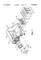
- FIG. 1is a partially exploded view of an exemplary printhead cartridge assembly cleaned by the present invention.
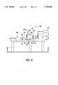
- FIG. 2is a side view of the assembly of FIG. 1, without the ink tanks, placed in a cleaning position in an automated cleaning system.
- FIG. 3is a top view of the cleaning system of FIG. 2.
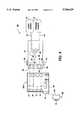
- FIG. 4is an enlarged view of the liquid cleaning assembly section of FIG. 2.
- the principles of the present inventionapply to the cleaning of various types of printheads supplied with ink from a variety of sources.
- the generic structure of the printhead to be cleanedincludes a manifold member which fluidly feeds ink from an ink source into the interior channels of the printhead.
- the inkis expelled through nozzles upon application of heat to a resistor in the channel (for thermal ink jet printing) or application of a voltage across a transducer to construct the ink filled channels causing the ink ejection (piezoelectric ink jet printing).
- the ink sourcecan be an ink bag, a solid housing (cartridge) filled with ink or with an ink impregnated foam. With either type of source, an ink exit port is fluidly and sealingly connected to the ink manifold of the printhead and, thence, into the interior ink pathways of the printhead.
- FIG. 1shows a color printhead assembly of the type wherein ink is supplied from an ink-filled foam contained within a plurality of ink cartridges.
- color printhead assembly 10comprises a segmented printhead 12 which has four segments, or groups, of nozzles (not visible), each group associated with printing ink of a different color onto a recording medium.
- the printhead segmentsare fabricated by methods known in the art and disclosed, for example, in U.S. Pat. No. 4,638 337, whose contents are hereby incorporated by reference.
- printhead 12is formed by bonding together a channel plate to a heater plate forming interior channels, each channel in thermal communication with a resistor element.
- Nozzlesare formed on the front face of the printhead and overlain with a nozzle plate 13.
- Ink from ink cartridges 14, 15, 16, 17is supplied via ink pipes 18, 19, 20, 21, respectively, of manifold 22 to the associated segments of printhead 12.
- the inkis filtered and sealed from leakage by internal seals and filters not visible.
- ink in the channelsis heated and expelled through the nozzles of the particular recording printhead segment.
- the printheadis bonded to heat sink 24 which has three holes 26 formed in surface 28 for purposes to be discussed later.
- the heat sink and manifoldare mounted on a housing frame 30 which has a floor 32 which seats the manifold and the ink cartridges.
- the housingalso has side walls 34, 36 and a partial roof 38.
- the printhead 12 and housing frame 30, minus the cartridgeswill be referred to as printhead housing assembly.
- ink cartridges 14-17are shown removed from the frame 30. For purposes of description, it is assumed that the cartridge had been installed during a print/test mode and been successfully tested and the cartridges have been partially or completely exhausted of ink.
- the printhead assembly 10is to be packed and shipped to a location where it will be installed in a printer with new cartridges. It is, therefore, necessary at this point to thoroughly clean the printhead, the manifold and the internal ink paths connecting the manifold to the printhead nozzles.
- the printhead housing assembly 30A(printhead assembly 10 minus the cartridges) is placed in an automated cleaning fixture shown in side view in FIG. 2 and in top view in FIG. 3.
- a liquid cleaning mixtureis injected into manifold 22, passes through the internal ink paths and is withdrawn through the nozzles by application of a vacuum applied across the printhead nozzle plate 13.
- automatic cleaning fixture 40comprises a table 42 having a raised platform 44 with three datum points 46.
- Printhead housing assembly 30Ais tilted and positioned so that the heat sink holes 26 are seated over datum points 46.
- An automated "CLEAN" modeis enabled at this point.
- Clamp 48moves downward to press against housing side wall 36 with about four pounds of force clamping the housing in place.
- a vacuum cap assembly 50is moved in the direction of arrow 52 until a gasket cap 53 is sealingly engaged over nozzle plate 13 providing a suitable vacuum force at each nozzle.
- Assembly 50is of the type used to prime a printhead in a maintenance station and is disclosed in detail in, for example, U.S. Pat. No. 5,257,044, whose contents are hereby incorporated by reference.
- liquid cleaning assembly 54is moved in the direction of arrow 56 until a manifold interface member 58 is sealingly seated over ink pipes 18-21 of manifold 22.
- Member 58comprises a silicone rubber gasket element 60 bonded to a liquid supply slotted plate 62.
- Element 60has four holes 64 formed with a diameter slightly larger than the diameter of ink pipes 18-21.
- Plate 62has an entrance port 66 connected to tube 68. Port 66 is connected to a slot 70 which communicates with holes 64.
- Assembly 54further includes a source 72 of cleaning liquid (deionized water in the preferred embodiment), a source 74 of a gas, nitrogen in the preferred embodiment, and tubes 76, 78 which convey the water and nitrogen respectively to toggle valve 80 operated by solenoid 81.
- tubes 68, 76, 78are 1/4" polyurethane; nitrogen supply pressure is regulated at between 7 and 15 psi, and the vacuum pressure at vacuum cap assembly 50 is set at between 4" and 15" mercury.
- the cleaning liquidis deionized water with 0.05% Dowicil 200 biocide.
- the automated clean operationbegins with energization of an appropriate "start clean" switch following seating of the printhead housing assembly 30A.
- Clamp 48moves downward to clamp the housing assembly into place.
- Vacuum assembly 50moves in the direction of arrow 52 until gasket cap 53 is sealingly engaged over the nozzle plate 13, and the vacuum is applied.
- Cleaning assembly 54moves in the direction of arrow 56 until manifold interface member 58 is connected to manifold 22; e.g. when holes 64 of silicon element 60 slide over and seat on ink pipes 18-21.
- the water and nitrogen sources 72, 74are activated and ink begins to be withdrawn from the printhead nozzles due to the vacuum pressure exerted by vacuum assembly 50.
- the ink, and later the cleaning fluidis deposited in a waste container (not shown but part of assembly 50).
- Solenoid 81is energized so as to toggle valve 80 at 500 millisecond intervals (50% duty cycle) for 6 seconds.
- the cleaning mixture flowing through tube 68comprises the deionized water carrying nitrogen bubbles 82.
- the cleaning mixtureenters plate 62 through port 66, flows along slot 70, through holes 64, ink pipes 18-21, and along internal printhead channel paths.
- the cleaning mixtureprovides a thorough cleaning of the manifold and the interior channels of the printhead, flushing out any residual ink through the nozzles.
- a second clean cycleis activated which passes nitrogen only through valve 80 for approximately 6 seconds; a 50% duty cycle is activated for another 6 seconds, and nitrogen only is passed through for 10 seconds.
- the water and nitrogen sourceare turned off and the cycle ends when all of the liquid mixture has been expelled out of the printhead.
- the liquid cleaning assembly 54, vacuum cap assembly 50 and clamp 48are withdrawn, and housing 30 is removed and oven dried. In a preferred embodiment, oven drying is at 100° C. for 40-60 minutes.
- a non-contact wiper head 90may be added to the automated fixture 40. Assembly 90 is positioned beneath clamped printhead housing assembly 30 and, when activated at the end of the clean cycles, moves upward in the direction of arrow 91 and presents a vacuum head 92 in close proximity (0.005" optimum) to the nozzle face. A vacuum of 27" mercury is applied to the head by conventional means not shown, and any residual ink on the nozzle face is drawn away and into the vacuum head in a waste container contained therein. The assembly is then lowered to its initial position.
- a printhead housingis clamped into a cleaning position and a vacuum applied to the nozzle face.
- a cleaning liquid/gas mixtureis forced through the printhead assembly manifold, along internal ink paths and through the printhead nozzles.
- the liquid/gas mixtureprovides enhanced cleaning of the printhead. It is believed the gas (nitrogen) bubbles provide a superior removal of residual ink and particulate matter.
- the color printhead assemblycould include four ink cartridges, each with its associated individual printheads as disclosed, for example, in U.S. Pat. No. 4,571,599.
- the cleaning methodcan be used to clean full width ink jet printheads of the type disclosed, for example, in U.S. Pat. No. 5,160,945.
- the cleaning methodcan be used to clean a single color printhead with an associated cartridge as disclosed, for example, in U.S. Pat. No. 5,289,212.
- the automatic cleaning fixtureand especially the manifold interface member, is modified so as to introduce the cleaning mixture into the specific manifold design of the printhead to be cleaned.
- One skilled in the artcan modify the interface member so as to introduce the cleaning fixture into the printhead interior.
- nitrogenhas been used as the preferred gas to be combined into the cleaning fluid mixture
- other inert noble gasescan be used such as argon, helium, and carbon dioxide.
Landscapes
- Ink Jet (AREA)
Abstract
Description
Claims (9)
Priority Applications (1)
| Application Number | Priority Date | Filing Date | Title |
|---|---|---|---|
| US08/673,479US5786829A (en) | 1996-07-01 | 1996-07-01 | Apparatus and method for cleaning an ink flow path of an ink jet printhead |
Applications Claiming Priority (1)
| Application Number | Priority Date | Filing Date | Title |
|---|---|---|---|
| US08/673,479US5786829A (en) | 1996-07-01 | 1996-07-01 | Apparatus and method for cleaning an ink flow path of an ink jet printhead |
Publications (1)
| Publication Number | Publication Date |
|---|---|
| US5786829Atrue US5786829A (en) | 1998-07-28 |
Family
ID=24702818
Family Applications (1)
| Application Number | Title | Priority Date | Filing Date |
|---|---|---|---|
| US08/673,479Expired - LifetimeUS5786829A (en) | 1996-07-01 | 1996-07-01 | Apparatus and method for cleaning an ink flow path of an ink jet printhead |
Country Status (1)
| Country | Link |
|---|---|
| US (1) | US5786829A (en) |
Cited By (30)
| Publication number | Priority date | Publication date | Assignee | Title |
|---|---|---|---|---|
| US6003983A (en)* | 1997-11-18 | 1999-12-21 | Lexmark International, Inc. | Contaminant cleaned inkjet cartridge manufacture |
| US6106107A (en)* | 1996-10-21 | 2000-08-22 | Jemtex Ink Jet Printing Ltd. | Apparatus and method for multi-jet generation of high viscosity fluid and channel construction particularly useful therein |
| US6142601A (en)* | 1998-12-04 | 2000-11-07 | Eastman Kodak Company | Self-cleaning ink jet printer with reverse fluid flow and method of assembling the printer |
| EP1060894A1 (en)* | 1999-06-16 | 2000-12-20 | Eastman Kodak Company | Multi-fluidic cleaning for ink jet print heads |
| EP1070592A1 (en)* | 1999-07-23 | 2001-01-24 | Mutoh Industries Ltd. | Ink jet printer and method for operating the same |
| EP1101616A1 (en)* | 1999-11-22 | 2001-05-23 | Agilent Technologies Inc. | Cleaning printheads |
| US6342105B1 (en)* | 1997-11-21 | 2002-01-29 | Fuji Xerox Co., Ltd. | Washing solution for ink jet head, method for producing the same, and method for washing ink jet head using the same |
| US6382763B1 (en) | 2000-01-24 | 2002-05-07 | Praxair Technology, Inc. | Ink jet printing |
| US6491387B1 (en)* | 2000-09-18 | 2002-12-10 | Rodney Bruce Mayfield | Ink jet cleaning method and apparatus utilizing vacuum impregnation and centrifuge |
| US20030081046A1 (en)* | 2001-10-31 | 2003-05-01 | Scitex Digital Printing, Inc. | Shutdown for an ink jet printer |
| US20040160474A1 (en)* | 2003-02-14 | 2004-08-19 | Harrison Mark A. | Printer head cleaning system and method |
| US20050007623A1 (en)* | 2001-10-01 | 2005-01-13 | Canon Kabushiki Kaisha | Printer and method for controlling same |
| US20050128260A1 (en)* | 2003-12-12 | 2005-06-16 | Shyh-Haur Su | Apparatus and method for introducing micro-volume liquid |
| WO2006114633A1 (en)* | 2005-04-27 | 2006-11-02 | Xaar Technology Limited | Method of sterilisation |
| US20070076043A1 (en)* | 2005-10-03 | 2007-04-05 | Brother Kogyo Kabushiki Kaisha | Ink-Jet Recording Apparatus |
| US20080024545A1 (en)* | 2006-07-31 | 2008-01-31 | Silverbrook Research Pty Ltd | Method of removing particulates from a printhead using a liquid foam |
| US20080024547A1 (en)* | 2006-07-31 | 2008-01-31 | Silverbrook Research Pty Ltd | Printhead assembly with ink supply system and foaming system |
| US20090135220A1 (en)* | 2007-11-27 | 2009-05-28 | Xerox Corporation | Off-line printhead inspection and recovery unit for production piezo ink jet architectures |
| US20090213157A1 (en)* | 2005-02-08 | 2009-08-27 | Franz Obertegger | Inkjet Printing Device and Method for Printing Multi-Coloured Images |
| US20100079536A1 (en)* | 2006-07-31 | 2010-04-01 | Silverbrook Research Pty Ltd | Printhead maintenance system for applying foam to printhead |
| US20100225715A1 (en)* | 2009-03-04 | 2010-09-09 | Hewlett-Packard Development Company, L.P. | Automatic cleaning in a liquid ink printing system |
| EP2233295A1 (en)* | 2009-03-27 | 2010-09-29 | Brother Kogyo Kabushiki Kaisha | Cleaner unit, printing apparatus, and method to clean a printing apparatus |
| CN103386816A (en)* | 2012-05-11 | 2013-11-13 | 科迪华公司 | Printhead unit assembly for an inkjet printing system |
| US20130321535A1 (en)* | 2012-04-17 | 2013-12-05 | Kateeva, Inc. | Printhead unit assembly for use with an inkjet printing system |
| CN103770465A (en)* | 2012-10-22 | 2014-05-07 | 富士胶片株式会社 | Nozzle plate maintenance for fluid ejection devices |
| TWI613098B (en)* | 2012-05-11 | 2018-02-01 | 凱特伊夫公司 | Printhead unit assembly for use with an inkjet printing system |
| US10457059B2 (en) | 2016-07-18 | 2019-10-29 | Kateeva, Inc. | Printing system assemblies and techniques |
| US10875319B2 (en)* | 2019-02-26 | 2020-12-29 | Seiko Epson Corporation | Method of cleaning liquid discharging apparatus |
| US11412964B2 (en) | 2008-05-05 | 2022-08-16 | Masimo Corporation | Pulse oximetry system with electrical decoupling circuitry |
| US20230029407A1 (en)* | 2019-12-20 | 2023-01-26 | Dürr Systems Ag | Cleaning device for cleaning a nozzle applicator and corresponding cleaning method |
Citations (9)
| Publication number | Priority date | Publication date | Assignee | Title |
|---|---|---|---|---|
| US4571599A (en)* | 1984-12-03 | 1986-02-18 | Xerox Corporation | Ink cartridge for an ink jet printer |
| US4849769A (en)* | 1987-06-02 | 1989-07-18 | Burlington Industries, Inc. | System for ultrasonic cleaning of ink jet orifices |
| US4849774A (en)* | 1977-10-03 | 1989-07-18 | Canon Kabushiki Kaisha | Bubble jet recording apparatus which projects droplets of liquid through generation of bubbles in a liquid flow path by using heating means responsive to recording signals |
| US5160945A (en)* | 1991-05-10 | 1992-11-03 | Xerox Corporation | Pagewidth thermal ink jet printhead |
| US5210550A (en)* | 1991-12-23 | 1993-05-11 | Xerox Corporation | Maintenance station for ink jet printers |
| WO1993017867A1 (en)* | 1992-03-12 | 1993-09-16 | Willett International Limited | Method for flushing an ink flow system |
| US5257044A (en)* | 1992-11-12 | 1993-10-26 | Xerox Corporation | Cap actuation mechanism for capping ink jet printheads |
| US5289212A (en)* | 1992-05-19 | 1994-02-22 | Xerox Corporation | Air vent for an ink supply cartridge in a thermal ink-jet printer |
| US5574485A (en)* | 1994-10-13 | 1996-11-12 | Xerox Corporation | Ultrasonic liquid wiper for ink jet printhead maintenance |
- 1996
- 1996-07-01USUS08/673,479patent/US5786829A/ennot_activeExpired - Lifetime
Patent Citations (9)
| Publication number | Priority date | Publication date | Assignee | Title |
|---|---|---|---|---|
| US4849774A (en)* | 1977-10-03 | 1989-07-18 | Canon Kabushiki Kaisha | Bubble jet recording apparatus which projects droplets of liquid through generation of bubbles in a liquid flow path by using heating means responsive to recording signals |
| US4571599A (en)* | 1984-12-03 | 1986-02-18 | Xerox Corporation | Ink cartridge for an ink jet printer |
| US4849769A (en)* | 1987-06-02 | 1989-07-18 | Burlington Industries, Inc. | System for ultrasonic cleaning of ink jet orifices |
| US5160945A (en)* | 1991-05-10 | 1992-11-03 | Xerox Corporation | Pagewidth thermal ink jet printhead |
| US5210550A (en)* | 1991-12-23 | 1993-05-11 | Xerox Corporation | Maintenance station for ink jet printers |
| WO1993017867A1 (en)* | 1992-03-12 | 1993-09-16 | Willett International Limited | Method for flushing an ink flow system |
| US5289212A (en)* | 1992-05-19 | 1994-02-22 | Xerox Corporation | Air vent for an ink supply cartridge in a thermal ink-jet printer |
| US5257044A (en)* | 1992-11-12 | 1993-10-26 | Xerox Corporation | Cap actuation mechanism for capping ink jet printheads |
| US5574485A (en)* | 1994-10-13 | 1996-11-12 | Xerox Corporation | Ultrasonic liquid wiper for ink jet printhead maintenance |
Non-Patent Citations (2)
| Title |
|---|
| Mitchell et al. "Start-Stop Technique for Ink Jet Systems", IBM Technical Disclosure Bulletin, vol. 20 No. 1, Jun. 1977. |
| Mitchell et al. Start Stop Technique for Ink Jet Systems , IBM Technical Disclosure Bulletin, vol. 20 No. 1, Jun. 1977.* |
Cited By (62)
| Publication number | Priority date | Publication date | Assignee | Title |
|---|---|---|---|---|
| US6106107A (en)* | 1996-10-21 | 2000-08-22 | Jemtex Ink Jet Printing Ltd. | Apparatus and method for multi-jet generation of high viscosity fluid and channel construction particularly useful therein |
| US6003983A (en)* | 1997-11-18 | 1999-12-21 | Lexmark International, Inc. | Contaminant cleaned inkjet cartridge manufacture |
| US6342105B1 (en)* | 1997-11-21 | 2002-01-29 | Fuji Xerox Co., Ltd. | Washing solution for ink jet head, method for producing the same, and method for washing ink jet head using the same |
| US6142601A (en)* | 1998-12-04 | 2000-11-07 | Eastman Kodak Company | Self-cleaning ink jet printer with reverse fluid flow and method of assembling the printer |
| EP1060894A1 (en)* | 1999-06-16 | 2000-12-20 | Eastman Kodak Company | Multi-fluidic cleaning for ink jet print heads |
| US6196657B1 (en) | 1999-06-16 | 2001-03-06 | Eastman Kodak Company | Multi-fluidic cleaning for ink jet print heads |
| EP1070592A1 (en)* | 1999-07-23 | 2001-01-24 | Mutoh Industries Ltd. | Ink jet printer and method for operating the same |
| US6796634B2 (en) | 1999-11-22 | 2004-09-28 | Agilent Technologies, Inc. | Method and apparatus to clean an inkjet reagent deposition device |
| US7008037B2 (en) | 1999-11-22 | 2006-03-07 | Agilent Technologies, Inc. | Method and apparatus to clean an inkjet reagent deposition device |
| US6446642B1 (en) | 1999-11-22 | 2002-09-10 | Agilent Technologies, Inc. | Method and apparatus to clean an inkjet reagent deposition device |
| EP1101616A1 (en)* | 1999-11-22 | 2001-05-23 | Agilent Technologies Inc. | Cleaning printheads |
| US20050116986A1 (en)* | 1999-11-22 | 2005-06-02 | Caren Michael P. | Method and apparatus to clean an inkjet reagent deposition device |
| US6382763B1 (en) | 2000-01-24 | 2002-05-07 | Praxair Technology, Inc. | Ink jet printing |
| US6491387B1 (en)* | 2000-09-18 | 2002-12-10 | Rodney Bruce Mayfield | Ink jet cleaning method and apparatus utilizing vacuum impregnation and centrifuge |
| US20050007623A1 (en)* | 2001-10-01 | 2005-01-13 | Canon Kabushiki Kaisha | Printer and method for controlling same |
| US7349122B2 (en)* | 2001-10-01 | 2008-03-25 | Canon Kabushiki Kaisha | Printer and method for controlling same |
| US20030081046A1 (en)* | 2001-10-31 | 2003-05-01 | Scitex Digital Printing, Inc. | Shutdown for an ink jet printer |
| US6679590B2 (en)* | 2001-10-31 | 2004-01-20 | Scitex Digital Printing, Inc. | Shutdown for an ink jet printer |
| US20040160474A1 (en)* | 2003-02-14 | 2004-08-19 | Harrison Mark A. | Printer head cleaning system and method |
| US6871935B2 (en)* | 2003-02-14 | 2005-03-29 | Philip Morris Usa Inc. | Printer head cleaning system and method |
| US20050128260A1 (en)* | 2003-12-12 | 2005-06-16 | Shyh-Haur Su | Apparatus and method for introducing micro-volume liquid |
| CN100340471C (en)* | 2003-12-12 | 2007-10-03 | 财团法人工业技术研究院 | Trace liquid filling method and device |
| US6991311B2 (en)* | 2003-12-12 | 2006-01-31 | Industrial Technology Research Institute | Apparatus and method for introducing micro-volume liquid |
| US8764148B2 (en) | 2005-02-08 | 2014-07-01 | Durst Phototechnik—A.G. | Inkjet printing device and method for printing multi-colored images |
| US8141981B2 (en) | 2005-02-08 | 2012-03-27 | Durst Phototechnik - A.G. | Inkjet printing device and method for printing multi-coloured images |
| US20090213157A1 (en)* | 2005-02-08 | 2009-08-27 | Franz Obertegger | Inkjet Printing Device and Method for Printing Multi-Coloured Images |
| WO2006114633A1 (en)* | 2005-04-27 | 2006-11-02 | Xaar Technology Limited | Method of sterilisation |
| US20070076043A1 (en)* | 2005-10-03 | 2007-04-05 | Brother Kogyo Kabushiki Kaisha | Ink-Jet Recording Apparatus |
| US7731325B2 (en)* | 2005-10-03 | 2010-06-08 | Brother Kogyo Kabushiki Kaisha | Ink-jet recording apparatus |
| US20090289988A1 (en)* | 2006-07-31 | 2009-11-26 | Silverbrook Research Pty Ltd | Method Of Cleaning A Printhead Using Liquid Foam |
| US8382234B2 (en) | 2006-07-31 | 2013-02-26 | Zamtec Ltd | Printhead maintenance system for applying foam to printhead |
| US20100079536A1 (en)* | 2006-07-31 | 2010-04-01 | Silverbrook Research Pty Ltd | Printhead maintenance system for applying foam to printhead |
| US7753470B2 (en)* | 2006-07-31 | 2010-07-13 | Silverbrook Research Pty Ltd | Printhead assembly with ink supply system and foaming system |
| US20080024545A1 (en)* | 2006-07-31 | 2008-01-31 | Silverbrook Research Pty Ltd | Method of removing particulates from a printhead using a liquid foam |
| US7581812B2 (en)* | 2006-07-31 | 2009-09-01 | Silverbrook Research Pty Ltd | Method of removing particulates from a printhead using a liquid foam |
| US20100271442A1 (en)* | 2006-07-31 | 2010-10-28 | Silverbrook Research Pty Ltd | Printer with foaming system for cleaning ejecting face |
| US7922285B2 (en)* | 2006-07-31 | 2011-04-12 | Silverbrook Research Pty Ltd | Method of cleaning a printhead using liquid foam |
| US8100517B2 (en)* | 2006-07-31 | 2012-01-24 | Silverbrook Research Pty Ltd | Printer with foaming system for cleaning ejecting face |
| US20080024547A1 (en)* | 2006-07-31 | 2008-01-31 | Silverbrook Research Pty Ltd | Printhead assembly with ink supply system and foaming system |
| US20090135220A1 (en)* | 2007-11-27 | 2009-05-28 | Xerox Corporation | Off-line printhead inspection and recovery unit for production piezo ink jet architectures |
| US8262187B2 (en) | 2007-11-27 | 2012-09-11 | Xerox Corporation | Off-line printhead inspection and recovery unit for production piezo ink jet architectures |
| US11412964B2 (en) | 2008-05-05 | 2022-08-16 | Masimo Corporation | Pulse oximetry system with electrical decoupling circuitry |
| US20100225715A1 (en)* | 2009-03-04 | 2010-09-09 | Hewlett-Packard Development Company, L.P. | Automatic cleaning in a liquid ink printing system |
| US8322831B2 (en)* | 2009-03-04 | 2012-12-04 | Hewlett-Packard Development Company, L.P. | Automatic cleaning in a liquid ink printing system |
| US8297732B2 (en)* | 2009-03-27 | 2012-10-30 | Brother Kogyo Kabushiki Kaisha | Printing apparatus and cleaner unit for cleaning inkjet head and ink conveyer tube |
| US20100245461A1 (en)* | 2009-03-27 | 2010-09-30 | Brother Kogyo Kabushiki Kaisha | Cleaner unit, printing apparatus, and method to clean a printing apparatus |
| EP2233295A1 (en)* | 2009-03-27 | 2010-09-29 | Brother Kogyo Kabushiki Kaisha | Cleaner unit, printing apparatus, and method to clean a printing apparatus |
| US20130321535A1 (en)* | 2012-04-17 | 2013-12-05 | Kateeva, Inc. | Printhead unit assembly for use with an inkjet printing system |
| US9505215B2 (en)* | 2012-04-17 | 2016-11-29 | Kateeva, Inc. | Printhead unit assembly for use with an inkjet printing system |
| US8714719B2 (en)* | 2012-04-17 | 2014-05-06 | Kateeva, Inc. | Printhead unit assembly for use with an inkjet printing system |
| US10493763B2 (en) | 2012-04-17 | 2019-12-03 | Kateeva, Inc. | Printhead unit assembly for use with an inkjet printing system |
| CN103386816B (en)* | 2012-05-11 | 2016-01-20 | 科迪华公司 | Printhead unit assembly for an inkjet printing system |
| TWI613098B (en)* | 2012-05-11 | 2018-02-01 | 凱特伊夫公司 | Printhead unit assembly for use with an inkjet printing system |
| TWI667148B (en)* | 2012-05-11 | 2019-08-01 | 美商凱特伊夫公司 | Printing system, modular printhead unit for use in printing system, and related method of fabricating a layer of an electronic product on a substrate |
| TWI687324B (en)* | 2012-05-11 | 2020-03-11 | 美商凱特伊夫公司 | A printing system |
| CN103386816A (en)* | 2012-05-11 | 2013-11-13 | 科迪华公司 | Printhead unit assembly for an inkjet printing system |
| CN103770465B (en)* | 2012-10-22 | 2016-08-17 | 富士胶片株式会社 | Ink jet-print head and method for ink jet printing |
| CN103770465A (en)* | 2012-10-22 | 2014-05-07 | 富士胶片株式会社 | Nozzle plate maintenance for fluid ejection devices |
| US8870341B2 (en)* | 2012-10-22 | 2014-10-28 | Fujifilm Corporation | Nozzle plate maintenance for fluid ejection devices |
| US10457059B2 (en) | 2016-07-18 | 2019-10-29 | Kateeva, Inc. | Printing system assemblies and techniques |
| US10875319B2 (en)* | 2019-02-26 | 2020-12-29 | Seiko Epson Corporation | Method of cleaning liquid discharging apparatus |
| US20230029407A1 (en)* | 2019-12-20 | 2023-01-26 | Dürr Systems Ag | Cleaning device for cleaning a nozzle applicator and corresponding cleaning method |
Similar Documents
| Publication | Publication Date | Title |
|---|---|---|
| US5786829A (en) | Apparatus and method for cleaning an ink flow path of an ink jet printhead | |
| US5923347A (en) | Method and system for cleaning an ink jet printhead | |
| JP4635618B2 (en) | Filling method and liquid ejection device | |
| US7918530B2 (en) | Apparatus and method for cleaning an inkjet printhead | |
| JPH09123473A (en) | Device for refilling ink-jet cartridge | |
| JPH106521A (en) | Liquid replenishment method, liquid supply device and liquid ejection recording device | |
| CA2060618A1 (en) | Priming apparatus and process for multi-color ink-jet pens | |
| US7213902B2 (en) | Method of shutting down a continuous ink jet printer for maintaining positive pressure at the printhead | |
| JPH06143599A (en) | Ink jet printer maintenance device | |
| JPH07266573A (en) | Valve connector of thermal ink jet printing bar and ink processing system | |
| JPH11170559A (en) | Ink jet coartridge | |
| US6302533B1 (en) | Adsorbent for ink jet use, an ink retaining container, an adsorption member using such adsorbent, an ink supply system having such adsorption member, and an ink jet recording apparatus | |
| US6130684A (en) | Maintenance station for an ink jet printhead with improved capping and wiping system | |
| US6402293B1 (en) | Vacuum accumulator and ink manifold | |
| JPS61130054A (en) | Ink jet printer | |
| US8038256B2 (en) | Discharging apparatus and removing method | |
| JPH04284256A (en) | Ink-jet printing device | |
| JP4442980B2 (en) | How to service an inkjet printhead | |
| JPH10329342A (en) | Method and apparatus for removing air from ink jet type print head | |
| US6003983A (en) | Contaminant cleaned inkjet cartridge manufacture | |
| KR100726426B1 (en) | Ink cartridge and its manufacturing method | |
| JP2004291242A (en) | Inkjet recording device | |
| JPH058400A (en) | Inkjet recording device | |
| JP4687063B2 (en) | Cleaning method and replacement method | |
| JP2006198845A (en) | Filling method and liquid ejection device |
Legal Events
| Date | Code | Title | Description |
|---|---|---|---|
| AS | Assignment | Owner name:XEROX CORPORATION, CONNECTICUT Free format text:ASSIGNMENT OF ASSIGNORS INTEREST;ASSIGNORS:PASCIAK, DONALD J. JR.;KLINO, MARK E.;REEL/FRAME:008102/0534 Effective date:19960625 | |
| STCF | Information on status: patent grant | Free format text:PATENTED CASE | |
| FPAY | Fee payment | Year of fee payment:4 | |
| AS | Assignment | Owner name:BANK ONE, NA, AS ADMINISTRATIVE AGENT, ILLINOIS Free format text:SECURITY INTEREST;ASSIGNOR:XEROX CORPORATION;REEL/FRAME:013153/0001 Effective date:20020621 | |
| AS | Assignment | Owner name:JPMORGAN CHASE BANK, AS COLLATERAL AGENT, TEXAS Free format text:SECURITY AGREEMENT;ASSIGNOR:XEROX CORPORATION;REEL/FRAME:015134/0476 Effective date:20030625 Owner name:JPMORGAN CHASE BANK, AS COLLATERAL AGENT,TEXAS Free format text:SECURITY AGREEMENT;ASSIGNOR:XEROX CORPORATION;REEL/FRAME:015134/0476 Effective date:20030625 | |
| FPAY | Fee payment | Year of fee payment:8 | |
| FPAY | Fee payment | Year of fee payment:12 | |
| AS | Assignment | Owner name:XEROX CORPORATION, CONNECTICUT Free format text:RELEASE BY SECURED PARTY;ASSIGNOR:JPMORGAN CHASE BANK, N.A. AS SUCCESSOR-IN-INTEREST ADMINISTRATIVE AGENT AND COLLATERAL AGENT TO JPMORGAN CHASE BANK;REEL/FRAME:066728/0193 Effective date:20220822 |